US5568865A - Surgical cable packaging apparatus - Google Patents
Surgical cable packaging apparatusDownload PDFInfo
- Publication number
- US5568865A US5568865AUS08/281,823US28182394AUS5568865AUS 5568865 AUS5568865 AUS 5568865AUS 28182394 AUS28182394 AUS 28182394AUS 5568865 AUS5568865 AUS 5568865A
- Authority
- US
- United States
- Prior art keywords
- cable
- tray
- track
- channel
- lead
- Prior art date
- Legal status (The legal status is an assumption and is not a legal conclusion. Google has not performed a legal analysis and makes no representation as to the accuracy of the status listed.)
- Expired - Lifetime
Links
- 238000004806packaging method and processMethods0.000titleclaimsdescription21
- 238000007789sealingMethods0.000claimsabstract2
- 238000003780insertionMethods0.000claimsdescription6
- 230000037431insertionEffects0.000claimsdescription6
- 230000003028elevating effectEffects0.000claimsdescription2
- 238000001356surgical procedureMethods0.000description10
- 210000000988bone and boneAnatomy0.000description7
- 239000012634fragmentSubstances0.000description6
- 238000011882arthroplastyMethods0.000description4
- 229920001903high density polyethylenePolymers0.000description3
- 239000004700high-density polyethyleneSubstances0.000description3
- 229910000684Cobalt-chromeInorganic materials0.000description2
- LYCAIKOWRPUZTN-UHFFFAOYSA-NEthylene glycolChemical compoundOCCOLYCAIKOWRPUZTN-UHFFFAOYSA-N0.000description2
- 229910045601alloyInorganic materials0.000description2
- 239000000956alloySubstances0.000description2
- 238000013459approachMethods0.000description2
- 239000010952cobalt-chromeSubstances0.000description2
- 238000013461designMethods0.000description2
- 208000014674injuryDiseases0.000description2
- 210000003127kneeAnatomy0.000description2
- 238000000034methodMethods0.000description2
- 239000010816packaging wasteSubstances0.000description2
- 239000004033plasticSubstances0.000description2
- 229920003023plasticPolymers0.000description2
- 230000008733traumaEffects0.000description2
- 210000000689upper legAnatomy0.000description2
- 241000287107PasserSpecies0.000description1
- -1Polyethylene TerephthalatePolymers0.000description1
- 230000004888barrier functionEffects0.000description1
- WGCNASOHLSPBMP-UHFFFAOYSA-NhydroxyacetaldehydeNatural productsOCC=OWGCNASOHLSPBMP-UHFFFAOYSA-N0.000description1
- 230000000642iatrogenic effectEffects0.000description1
- 239000007943implantSubstances0.000description1
- 238000012986modificationMethods0.000description1
- 230000004048modificationEffects0.000description1
- 239000003607modifierSubstances0.000description1
- 238000012856packingMethods0.000description1
- 239000000088plastic resinSubstances0.000description1
- 239000005020polyethylene terephthalateSubstances0.000description1
- 229920000139polyethylene terephthalatePolymers0.000description1
- 229920005644polyethylene terephthalate glycol copolymerPolymers0.000description1
- 230000002980postoperative effectEffects0.000description1
- 230000008569processEffects0.000description1
- 230000000069prophylactic effectEffects0.000description1
- 230000005855radiationEffects0.000description1
- 230000008439repair processEffects0.000description1
- 238000004804windingMethods0.000description1
Images

Classifications
- A—HUMAN NECESSITIES
- A61—MEDICAL OR VETERINARY SCIENCE; HYGIENE
- A61B—DIAGNOSIS; SURGERY; IDENTIFICATION
- A61B17/00—Surgical instruments, devices or methods
- A61B17/56—Surgical instruments or methods for treatment of bones or joints; Devices specially adapted therefor
- A61B17/58—Surgical instruments or methods for treatment of bones or joints; Devices specially adapted therefor for osteosynthesis, e.g. bone plates, screws or setting implements
- A61B17/68—Internal fixation devices, including fasteners and spinal fixators, even if a part thereof projects from the skin
- A61B17/82—Internal fixation devices, including fasteners and spinal fixators, even if a part thereof projects from the skin for bone cerclage
- A—HUMAN NECESSITIES
- A61—MEDICAL OR VETERINARY SCIENCE; HYGIENE
- A61B—DIAGNOSIS; SURGERY; IDENTIFICATION
- A61B17/00—Surgical instruments, devices or methods
- A61B17/04—Surgical instruments, devices or methods for suturing wounds; Holders or packages for needles or suture materials
- A61B17/06—Needles ; Sutures; Needle-suture combinations; Holders or packages for needles or suture materials
- A61B17/06114—Packages or dispensers for needles or sutures
- A61B17/06119—Packages or dispensers for needles or sutures of cylindrical shape
- A61B17/06123—Flat cylinders, e.g. including an inner reel
- A—HUMAN NECESSITIES
- A61—MEDICAL OR VETERINARY SCIENCE; HYGIENE
- A61F—FILTERS IMPLANTABLE INTO BLOOD VESSELS; PROSTHESES; DEVICES PROVIDING PATENCY TO, OR PREVENTING COLLAPSING OF, TUBULAR STRUCTURES OF THE BODY, e.g. STENTS; ORTHOPAEDIC, NURSING OR CONTRACEPTIVE DEVICES; FOMENTATION; TREATMENT OR PROTECTION OF EYES OR EARS; BANDAGES, DRESSINGS OR ABSORBENT PADS; FIRST-AID KITS
- A61F2/00—Filters implantable into blood vessels; Prostheses, i.e. artificial substitutes or replacements for parts of the body; Appliances for connecting them with the body; Devices providing patency to, or preventing collapsing of, tubular structures of the body, e.g. stents
- A61F2/02—Prostheses implantable into the body
- A61F2/30—Joints
- A61F2/32—Joints for the hip
- A61F2/36—Femoral heads ; Femoral endoprostheses
- A61F2/3662—Femoral shafts
- A61F2/367—Proximal or metaphyseal parts of shafts
- A—HUMAN NECESSITIES
- A61—MEDICAL OR VETERINARY SCIENCE; HYGIENE
- A61F—FILTERS IMPLANTABLE INTO BLOOD VESSELS; PROSTHESES; DEVICES PROVIDING PATENCY TO, OR PREVENTING COLLAPSING OF, TUBULAR STRUCTURES OF THE BODY, e.g. STENTS; ORTHOPAEDIC, NURSING OR CONTRACEPTIVE DEVICES; FOMENTATION; TREATMENT OR PROTECTION OF EYES OR EARS; BANDAGES, DRESSINGS OR ABSORBENT PADS; FIRST-AID KITS
- A61F2/00—Filters implantable into blood vessels; Prostheses, i.e. artificial substitutes or replacements for parts of the body; Appliances for connecting them with the body; Devices providing patency to, or preventing collapsing of, tubular structures of the body, e.g. stents
- A61F2/02—Prostheses implantable into the body
- A61F2/30—Joints
- A61F2/32—Joints for the hip
- A61F2/36—Femoral heads ; Femoral endoprostheses
- A61F2/3609—Femoral heads or necks; Connections of endoprosthetic heads or necks to endoprosthetic femoral shafts
- A61F2002/3625—Necks
- A61F2002/3631—Necks with an integral complete or partial peripheral collar or bearing shoulder at its base
- A—HUMAN NECESSITIES
- A61—MEDICAL OR VETERINARY SCIENCE; HYGIENE
- A61F—FILTERS IMPLANTABLE INTO BLOOD VESSELS; PROSTHESES; DEVICES PROVIDING PATENCY TO, OR PREVENTING COLLAPSING OF, TUBULAR STRUCTURES OF THE BODY, e.g. STENTS; ORTHOPAEDIC, NURSING OR CONTRACEPTIVE DEVICES; FOMENTATION; TREATMENT OR PROTECTION OF EYES OR EARS; BANDAGES, DRESSINGS OR ABSORBENT PADS; FIRST-AID KITS
- A61F2/00—Filters implantable into blood vessels; Prostheses, i.e. artificial substitutes or replacements for parts of the body; Appliances for connecting them with the body; Devices providing patency to, or preventing collapsing of, tubular structures of the body, e.g. stents
- A61F2/02—Prostheses implantable into the body
- A61F2/30—Joints
- A61F2/32—Joints for the hip
- A61F2/36—Femoral heads ; Femoral endoprostheses
- A61F2/3662—Femoral shafts
- A61F2002/3678—Geometrical features
- A61F2002/368—Geometrical features with lateral apertures, bores, holes or openings, e.g. for reducing the mass, for receiving fixation screws or for communicating with the inside of a hollow shaft
Definitions
- the present inventionrelates to a packaging apparatus for holding a surgical cable. More particularly, the present invention relates to a packaging tray configured to facilitate storage and use of the surgical cable, while providing a sterile environment for storing the surgical cable prior to use.
- a surgical cablein various types of surgical procedures, such as revision hip and knee arthroplasty or trauma fixation.
- Several preoperative conditionslend themselves to the use of such surgical cables.
- cableis used in reattachment of extended proximal femoral osteotomy fragments, or in revision hip and knee arthroplasty requiring fixation of strut graphs, fixation of host/graph junctions, or fixation of iatrogenic fractures.
- Surgical cableis also used for prophylactic cabling of a proximal end of a femur during total hip arthroplasty.
- cableis used to repair trauma fractures or for reattachment of trochanter after a trochanteric osteotomy.
- One known surgical cable systemis a CONTROLTM CABLE SYSTEM available from DePuy Inc. in Warsaw, Ind.
- the cableis illustratively made from a cobalt chrome alloy having a diameter of about 1.8 mm (0.071 inch) and a length of about 24 inches (60.96 cm).
- a 7 ⁇ 7 strand configurationis illustratively provided.
- Opposite ends of the cableare coupled together by a cable sleeve made from a cobalt chrome alloy.
- the cable sleevehas two apertures extending through a body portion thereof for receiving opposite ends of the cable therethrough.
- the cable sleevehas a low profile design, chamfered entrance holes, and a trapezoidal cross section.
- the present inventionis designed to provide an improved packaging tray for storing a surgical cable and a cable sleeve prior to a surgical procedure.
- Previous storage techniquesinvolve winding the surgical cable into a coil and then inserting the coiled cable into a medical peel pouch or open cavity thermal formed blister. The plastic pouch is then sealed to keep the cable sterile.
- a problem associated with storing the surgical cable in a plastic pouchis that the cable tends to unwind wildly or kink when removed from the pouch.
- a cable sleeve for use with the cablemust be either stored separately or put loosely into the sealed pouch. Therefore, during a surgical procedure, use of the cable is complicated due to the problems associated with storing and removing the sterile coiled cable from a sealed pouch.
- the present inventionprovides a packing apparatus configured to facilitate storage and use of the surgical cable and cable sleeve.
- the packaging apparatusprovides a sterile barrier to the product before surgery.
- the packaging apparatus of the present inventionadvantageously facilitates access to a free end portion of the cable. This facilitates the surgical procedure by making the surgical cable easier to handle in an operating room.
- the cableis removed from the packaging apparatus of the present invention without unwinding wildly or kinking.
- the packaging apparatus of the present inventionalso advantageously stores the cable sleeve in a predetermined portion of the packaging apparatus. This reduces the likelihood that the cable sleeve will be dropped or lost during opening of the packaging apparatus.
- the packaging apparatusreduces hospital inventory, improves handling in the operating room, and minimizes packaging waste.
- a trayfor storing a surgical cable.
- the trayincludes a body portion configured to define a track for receiving the cable, and a lead-in channel configured to guide the cable into the track.
- the body portionincludes a generally circular recessed portion configured to define an annular track extending around an outer periphery of the recessed portion.
- the lead-in channelis curved so that the cable enters the annular track in a direction generally tangential to the track.
- the annular trackincludes a ramp portion located adjacent an outlet of the lead-in channel for elevating the cable as the cable passes over the ramp.
- the lead-in channelalso includes a ramp surface for aligning a free end of the cable at an upwardly extending angle.
- the lead-in channelis formed to include means for holding the cable within the channel.
- the lead-in channelis formed by first and second raised surfaces, and the holding means includes first and second projections extending away from the first and second raised surfaces, respectively.
- the body portion of the trayincludes a wall configured to define a cavity sized to receive a cable sleeve.
- the wallis located adjacent the lead-in channel so that a free end of the cable extends over the cavity to hold the cable sleeve within the cavity.
- a recessed portionlocated adjacent lead-in channel to facilitate access to the free end of the cable.
- a packaging apparatusincludes a first cover configured to be sealed to a flange of the tray.
- the apparatusalso includes an outer tray having an interior region for receiving the sealed inner tray therein and a flange surrounding the interior region.
- a second coversealed to the flange of the outer tray.
- FIG. 1is a perspective view illustrating a postoperative example of an extended proximal femoral osteotomy fragment reattached to a host bone using a pair of surgical cables;
- FIG. 2is an exploded perspective view illustrating the packaging apparatus of the present invention for storing the surgical cable prior to a surgical procedure;
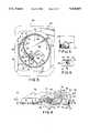
- FIG. 3is a top plan view illustrating details of an inner storage tray for holding the surgical cable and cable sleeve therein;
- FIG. 4is a sectional view taken along lines 4--4 of FIG. 3 illustrating the position of a free end of the surgical cable within the inner tray and illustrating the position of the cable sleeve which is held in a compartment formed in the inner packaging tray by the free end of the cable;
- FIG. 5is a sectional view taken along lines 5--5 of FIG. 3 illustrating the surgical cable stored in a slot or track formed around the outer periphery of the inner tray and illustrating a ramp formed along a bottom surface of the track to facilitate insertion of the cable into the storage track;
- FIG. 6is a sectional view taken along lines 6--6 of FIG. 4 illustrating the configuration of a lead-in guide channel for guiding insertion of the cable into the track in the inner tray.
- FIG. 1illustrates an example of the use of surgical cables in a surgical procedure.
- a host bone 10is illustratively a femur having an orthopaedic implant 12 installed in a proximal end portion 14.
- Host bone 10includes a osteotomy fragment 16 which must be reattached to host bone 10. Therefore, surgical cables 18 are used to hold fragment 16 to bone 10. Cables 18 are first wrapped around bone 10 and fragment 16 using an appropriate cable passer insert. The two free ends of the cable 18 are then passed through opposite ends of a cable sleeve 20. A tensioner is then applied to the cable to apply a predetermined tension force to the cable around the bone 10 and fragment 16.
- a crimper deviceis placed around the cable sleeve 20 to crimp sleeve 20 so that sleeve 20 holds cable 18 in proper tension.
- a cable cutteris then used to cut the free ends of the cable as flush as possible to cable sleeve 20.
- the present inventionprovides an improved packaging apparatus for storing the cable 18 and cable sleeve 20 prior to a surgical procedure.
- the packaging apparatusis illustrated in FIGS. 2-6.
- cable 18includes a first or leading end 22 and a second free end 24.
- the packaging apparatus of the present inventionincludes an inner tray 26 illustratively formed by thermal forming a sheet of plastic resin, illustratively in a plug assisted vacuum environment. It will be appreciated that various types of forming processes may be used to form tray 26.
- Tray 26may preferably be formed from Polyethylene Terephthalate with a glycol modifier(PETG). Tray 26 has a length of about 5.0 inches (12.7 cm) and a width of about 4.25 inches (10.8 cm).
- a sheet 28 of heat seal coated high density polyethylene (HDPE)is then sealed to an outer flange 30 of inner tray 26 in a conventional manner after a sterile cable 18 and sleeve 22 are loaded into tray 26 as discussed below.
- the packaging apparatus of the present inventionalso includes an outer tray 32 for receiving sealed inner tray 26.
- Outer tray 32includes an interior region 34 for receiving inner tray 26.
- a recessed portion 36is configured to receive flange 30 of inner tray 26.
- Positioning lugs 38are formed on opposite end portions of interior region 34.
- Another sheet 40 of high density polyethyleneis sealed to flange 42 of outer tray 32 after inner tray 26 is loaded into interior region 34.
- Outer flange 42has a length of about 6.25 inches (15.88 cm) and a width of about 5.25 inches (13.34 cm).
- Recessed portion 36has a length of about 5.115 inches (12.99 cm) and a width of about 4.39 inches (11.15 cm).
- inner tray 26includes a recessed, generally circular cable storage portion 44 extending below flange 30.
- Storage portion 44is configured to define a generally annular track portion 46 extending around an outer periphery of circular storage portion 44 for holding surgical cable 18 therein.
- Circular storage portion 44has a diameter of about 3.5 inches (8.9 cm).
- Storage portion 44includes first and second spaced apart raised sections 48 and 50 defining a lead-in channel 52 therebetween, and an open or recessed portion 54 located below raised portions 48 and 50.
- Recessed portion 54is configured to lie adjacent free end 24 of cable 18 to facilitate access to free end 24.
- a retaining wall 56is formed within recessed portion 54. Wall 56 defines a cavity 57 sized for holding a cable sleeve 20 therein.
- Circular storage portion 44is formed to extend about 0.56 inch (1.42 cm) below flange 30 as illustrated by dimension 59 in FIG. 4.
- FIG. 4illustrates a lead-in guide channel 52.
- Lead-in channel 52includes a ramp portion 58 aligned at an angle relative to bottom surface of circular portion 44 and relative to a plane of flange 30 of inner tray 26.
- a pinch point 61is formed by projections 60 and 62 located above lead-in ramp 58 on raised sections 48 and 50 as illustrated in FIGS. 3 and 6.
- pinch point 61has a dimension between projections 60 and 62 which is less than the diameter of cable 18 so that cable 18 will not move out of lead-in guide track 52.
- projections 60 and 62provide means for holding cable 18 within lead-in channel 52.
- the dimension between projections 60 and 62is about 0.060 inch (1.524 mm).
- the diameter of cable 18is about 1.8 mm (0.071 inch).
- lead-in channel 52is curved so that as first end 22 of cable 18 is inserted into lead-in channel 52 in the direction of arrow 64 in FIGS. 3 and 4, the curved channel 52 bends the cable 18 so that end 22 approaches track 46 generally tangential to the annular track 46 formed along the outer periphery of circular portion 44.
- This curved lead-in channel 52facilitates insertion of cable 18 into track 46.
- track 46is crimped along a top portion thereof to reduce the likelihood that cable 18 will be removed through the top of open track 46. This is illustrated in FIG. 4.
- An annular indented portion 66is formed around an outer periphery of circular portion 44 to prevent cable 18 from escaping through the open top portion of track 46.
- Track 46has a height dimension 45 of about 0.150 inch (3.81 mm) and a width dimension 47 of about 0.1 inch (2.54 mm).
- the open top of track 46has a dimension of about 0.050 inch (1.27 mm).
- FIG. 4also illustrates cable sleeve 20 having apertures 68 and 70 formed therein for receiving first and second ends 22 and 24, respectively, of cable 18.
- Cavity 57is formed adjacent the entry portion 72 of lead-in channel 52. Therefore, a portion of cable 18, held down by projections 60 and 62, holds cable sleeve 20 within cavity 57.
- free end 24 of cable 18provides a spring force against cable sleeve 20 in the direction of arrow 74 to retain cable sleeve 20 within cavity 57.
- Free end 24 of cable 18is aligned at an upperly extending angle relative to a plane of flange 30 to facilitate access to the free end 24 of cable 18 by a surgeon in the operating room.
- FIG. 4illustrates a finger 76 located within recessed portion 54 for easy gripping free end 24 of cable 18.
- a passive cable sleeve 20is first loaded into cavity 57 in a clean room environment.
- a passive cable 18is then loaded into inner tray 26.
- a leading first end 22 of cable 18is inserted into lead-in channel 52 below projections 60 and 62 in the direction of arrow 64.
- Cable 18is pushed into track 46 so that the cable 18 winds itself in track 46 in the direction of arrows 78 in FIG. 3.
- Tray 26is a form to include a ramp portion 80 located adjacent an outlet 81 of lead-in channel 52. Therefore, as leading end 22 of cable 18 approaches one full loop inside track 46, ramp 80 elevates the leading end 22 of cable 18 so that leading end 22 passes over the portion of cable 18 already in track 46.
- FIG. 5illustrates this layered cable and ramp feature.
- the sealed inner tray 26 with productremains sterilized while the packaging apparatus is shipped or stored.
- the outer surface of the outer tray 32 and cover 40may become contaminated during storage.
- the sterile inner tray 26is removed and taken into the sterile operating field.
- the cable 18 and cable sleeve 20are packaged together. This reduces hospital inventory and minimizes packaging waste.
- the improved design for inner tray 26also facilitates handling of cable 18 and cable sleeve 20 in the operating room.
Landscapes
- Health & Medical Sciences (AREA)
- Orthopedic Medicine & Surgery (AREA)
- Surgery (AREA)
- Life Sciences & Earth Sciences (AREA)
- Heart & Thoracic Surgery (AREA)
- Nuclear Medicine, Radiotherapy & Molecular Imaging (AREA)
- Engineering & Computer Science (AREA)
- Biomedical Technology (AREA)
- Neurology (AREA)
- Medical Informatics (AREA)
- Molecular Biology (AREA)
- Animal Behavior & Ethology (AREA)
- General Health & Medical Sciences (AREA)
- Public Health (AREA)
- Veterinary Medicine (AREA)
- Packaging Of Annular Or Rod-Shaped Articles, Wearing Apparel, Cassettes, Or The Like (AREA)
Abstract
Description
The present invention relates to a packaging apparatus for holding a surgical cable. More particularly, the present invention relates to a packaging tray configured to facilitate storage and use of the surgical cable, while providing a sterile environment for storing the surgical cable prior to use.
It is well known to use a surgical cable in various types of surgical procedures, such as revision hip and knee arthroplasty or trauma fixation. Several preoperative conditions lend themselves to the use of such surgical cables. For example, cable is used in reattachment of extended proximal femoral osteotomy fragments, or in revision hip and knee arthroplasty requiring fixation of strut graphs, fixation of host/graph junctions, or fixation of iatrogenic fractures. Surgical cable is also used for prophylactic cabling of a proximal end of a femur during total hip arthroplasty. In addition, cable is used to repair trauma fractures or for reattachment of trochanter after a trochanteric osteotomy.
One known surgical cable system is a CONTROL™ CABLE SYSTEM available from DePuy Inc. in Warsaw, Ind. The cable is illustratively made from a cobalt chrome alloy having a diameter of about 1.8 mm (0.071 inch) and a length of about 24 inches (60.96 cm). A 7×7 strand configuration is illustratively provided. Opposite ends of the cable are coupled together by a cable sleeve made from a cobalt chrome alloy. The cable sleeve has two apertures extending through a body portion thereof for receiving opposite ends of the cable therethrough. Preferably, the cable sleeve has a low profile design, chamfered entrance holes, and a trapezoidal cross section. An illustrative surgical procedure using a surgical cable is described in a brochure entitled "Control™ Cable--Hip Arthroplasty" from DePuy Inc. in Warsaw, Ind.
The present invention is designed to provide an improved packaging tray for storing a surgical cable and a cable sleeve prior to a surgical procedure. Previous storage techniques involve winding the surgical cable into a coil and then inserting the coiled cable into a medical peel pouch or open cavity thermal formed blister. The plastic pouch is then sealed to keep the cable sterile. A problem associated with storing the surgical cable in a plastic pouch is that the cable tends to unwind wildly or kink when removed from the pouch. In addition, a cable sleeve for use with the cable must be either stored separately or put loosely into the sealed pouch. Therefore, during a surgical procedure, use of the cable is complicated due to the problems associated with storing and removing the sterile coiled cable from a sealed pouch.
The present invention provides a packing apparatus configured to facilitate storage and use of the surgical cable and cable sleeve. In addition, the packaging apparatus provides a sterile barrier to the product before surgery. The packaging apparatus of the present invention advantageously facilitates access to a free end portion of the cable. This facilitates the surgical procedure by making the surgical cable easier to handle in an operating room. The cable is removed from the packaging apparatus of the present invention without unwinding wildly or kinking. The packaging apparatus of the present invention also advantageously stores the cable sleeve in a predetermined portion of the packaging apparatus. This reduces the likelihood that the cable sleeve will be dropped or lost during opening of the packaging apparatus. Advantageously, since the cable and sleeve are packaged together, the packaging apparatus reduces hospital inventory, improves handling in the operating room, and minimizes packaging waste.
According to one aspect of the invention, a tray is provided for storing a surgical cable. The tray includes a body portion configured to define a track for receiving the cable, and a lead-in channel configured to guide the cable into the track.
In the illustrated embodiment, the body portion includes a generally circular recessed portion configured to define an annular track extending around an outer periphery of the recessed portion. The lead-in channel is curved so that the cable enters the annular track in a direction generally tangential to the track.
The annular track includes a ramp portion located adjacent an outlet of the lead-in channel for elevating the cable as the cable passes over the ramp. The lead-in channel also includes a ramp surface for aligning a free end of the cable at an upwardly extending angle.
The lead-in channel is formed to include means for holding the cable within the channel. Illustratively, the lead-in channel is formed by first and second raised surfaces, and the holding means includes first and second projections extending away from the first and second raised surfaces, respectively.
The body portion of the tray includes a wall configured to define a cavity sized to receive a cable sleeve. The wall is located adjacent the lead-in channel so that a free end of the cable extends over the cavity to hold the cable sleeve within the cavity. A recessed portion located adjacent lead-in channel to facilitate access to the free end of the cable.
According to another aspect of the invention, a packaging apparatus includes a first cover configured to be sealed to a flange of the tray. The apparatus also includes an outer tray having an interior region for receiving the sealed inner tray therein and a flange surrounding the interior region. A second cover sealed to the flange of the outer tray.
Additional objects, features, and advantages of the invention will become apparent to those skilled in the art upon consideration of the following detailed description of the preferred embodiment exemplifying the best mode of carrying out the invention as presently perceived.
The detailed description particularly refers to the accompanying figures in which:
FIG. 1 is a perspective view illustrating a postoperative example of an extended proximal femoral osteotomy fragment reattached to a host bone using a pair of surgical cables;
FIG. 2 is an exploded perspective view illustrating the packaging apparatus of the present invention for storing the surgical cable prior to a surgical procedure;
FIG. 3 is a top plan view illustrating details of an inner storage tray for holding the surgical cable and cable sleeve therein;
FIG. 4 is a sectional view taken along lines 4--4 of FIG. 3 illustrating the position of a free end of the surgical cable within the inner tray and illustrating the position of the cable sleeve which is held in a compartment formed in the inner packaging tray by the free end of the cable;
FIG. 5 is a sectional view taken alonglines 5--5 of FIG. 3 illustrating the surgical cable stored in a slot or track formed around the outer periphery of the inner tray and illustrating a ramp formed along a bottom surface of the track to facilitate insertion of the cable into the storage track; and
FIG. 6 is a sectional view taken alonglines 6--6 of FIG. 4 illustrating the configuration of a lead-in guide channel for guiding insertion of the cable into the track in the inner tray.
Referring now to the drawings, FIG. 1 illustrates an example of the use of surgical cables in a surgical procedure. In the example of FIG. 1, ahost bone 10 is illustratively a femur having anorthopaedic implant 12 installed in aproximal end portion 14.Host bone 10 includes aosteotomy fragment 16 which must be reattached to hostbone 10. Therefore,surgical cables 18 are used to holdfragment 16 tobone 10.Cables 18 are first wrapped aroundbone 10 andfragment 16 using an appropriate cable passer insert. The two free ends of thecable 18 are then passed through opposite ends of acable sleeve 20. A tensioner is then applied to the cable to apply a predetermined tension force to the cable around thebone 10 andfragment 16. Once an appropriate amount of tension is applied tocables 18, a crimper device is placed around thecable sleeve 20 to crimpsleeve 20 so thatsleeve 20 holdscable 18 in proper tension. A cable cutter is then used to cut the free ends of the cable as flush as possible to cablesleeve 20.
The present invention provides an improved packaging apparatus for storing thecable 18 andcable sleeve 20 prior to a surgical procedure. The packaging apparatus is illustrated in FIGS. 2-6. Illustratively,cable 18 includes a first or leadingend 22 and a secondfree end 24. The packaging apparatus of the present invention includes aninner tray 26 illustratively formed by thermal forming a sheet of plastic resin, illustratively in a plug assisted vacuum environment. It will be appreciated that various types of forming processes may be used to formtray 26.Tray 26 may preferably be formed from Polyethylene Terephthalate with a glycol modifier(PETG).Tray 26 has a length of about 5.0 inches (12.7 cm) and a width of about 4.25 inches (10.8 cm). Asheet 28 of heat seal coated high density polyethylene (HDPE) is then sealed to anouter flange 30 ofinner tray 26 in a conventional manner after asterile cable 18 andsleeve 22 are loaded intotray 26 as discussed below. The packaging apparatus of the present invention also includes anouter tray 32 for receiving sealedinner tray 26.Outer tray 32 includes aninterior region 34 for receivinginner tray 26. A recessedportion 36 is configured to receiveflange 30 ofinner tray 26. Positioning lugs 38 are formed on opposite end portions ofinterior region 34. Anothersheet 40 of high density polyethylene is sealed to flange 42 ofouter tray 32 afterinner tray 26 is loaded intointerior region 34.Outer flange 42 has a length of about 6.25 inches (15.88 cm) and a width of about 5.25 inches (13.34 cm). Recessedportion 36 has a length of about 5.115 inches (12.99 cm) and a width of about 4.39 inches (11.15 cm).
As illustrated in FIG. 3,inner tray 26 includes a recessed, generally circularcable storage portion 44 extending belowflange 30.Storage portion 44 is configured to define a generallyannular track portion 46 extending around an outer periphery ofcircular storage portion 44 for holdingsurgical cable 18 therein.Circular storage portion 44 has a diameter of about 3.5 inches (8.9 cm).Storage portion 44 includes first and second spaced apart raisedsections channel 52 therebetween, and an open or recessedportion 54 located below raisedportions portion 54 is configured to lie adjacentfree end 24 ofcable 18 to facilitate access tofree end 24. A retainingwall 56 is formed within recessedportion 54.Wall 56 defines acavity 57 sized for holding acable sleeve 20 therein.Circular storage portion 44 is formed to extend about 0.56 inch (1.42 cm) belowflange 30 as illustrated bydimension 59 in FIG. 4.
FIG. 4 illustrates a lead-in guide channel 52. Lead-inchannel 52 includes aramp portion 58 aligned at an angle relative to bottom surface ofcircular portion 44 and relative to a plane offlange 30 ofinner tray 26. Apinch point 61 is formed byprojections in ramp 58 on raisedsections pinch point 61 has a dimension betweenprojections cable 18 so thatcable 18 will not move out of lead-inguide track 52. In other words,projections cable 18 within lead-inchannel 52. Illustratively, the dimension betweenprojections cable 18 is about 1.8 mm (0.071 inch).
As illustrated in FIG. 3, lead-inchannel 52 is curved so that asfirst end 22 ofcable 18 is inserted into lead-inchannel 52 in the direction ofarrow 64 in FIGS. 3 and 4, thecurved channel 52 bends thecable 18 so that end 22 approachestrack 46 generally tangential to theannular track 46 formed along the outer periphery ofcircular portion 44. This curved lead-inchannel 52 facilitates insertion ofcable 18 intotrack 46. Preferably, track 46 is crimped along a top portion thereof to reduce the likelihood thatcable 18 will be removed through the top ofopen track 46. This is illustrated in FIG. 4. An annularindented portion 66 is formed around an outer periphery ofcircular portion 44 to preventcable 18 from escaping through the open top portion oftrack 46.Track 46 has aheight dimension 45 of about 0.150 inch (3.81 mm) and awidth dimension 47 of about 0.1 inch (2.54 mm). The open top oftrack 46 has a dimension of about 0.050 inch (1.27 mm).
FIG. 4 also illustratescable sleeve 20 havingapertures 68 and 70 formed therein for receiving first and second ends 22 and 24, respectively, ofcable 18.Cavity 57 is formed adjacent theentry portion 72 of lead-inchannel 52. Therefore, a portion ofcable 18, held down byprojections cable sleeve 20 withincavity 57. In other words,free end 24 ofcable 18 provides a spring force againstcable sleeve 20 in the direction ofarrow 74 to retaincable sleeve 20 withincavity 57.Free end 24 ofcable 18 is aligned at an upperly extending angle relative to a plane offlange 30 to facilitate access to thefree end 24 ofcable 18 by a surgeon in the operating room. FIG. 4 illustrates afinger 76 located within recessedportion 54 for easy grippingfree end 24 ofcable 18.
During insertion, apassive cable sleeve 20 is first loaded intocavity 57 in a clean room environment. Apassive cable 18 is then loaded intoinner tray 26. A leadingfirst end 22 ofcable 18 is inserted into lead-inchannel 52 belowprojections arrow 64.Cable 18 is pushed intotrack 46 so that thecable 18 winds itself intrack 46 in the direction ofarrows 78 in FIG. 3.Tray 26 is a form to include aramp portion 80 located adjacent anoutlet 81 of lead-inchannel 52. Therefore, as leadingend 22 ofcable 18 approaches one full loopinside track 46,ramp 80 elevates theleading end 22 ofcable 18 so that leadingend 22 passes over the portion ofcable 18 already intrack 46. By moving the leadingend 22 ofcable 18 above the top of thecable 18 already inserted into thetrack 46, continued smooth insertion of thecable 18 intotrack 46 is facilitated. FIG. 5 illustrates this layered cable and ramp feature. After thesterile cable 18 is loaded intotray 26 with afree end 24 situated over recessedportion 54 for easy access and for holdingcable sleeve 20 in place withincavity 57,cover sheet 28 is secured to flange 30 ofinner tray 26 in a conventional manner. Sealedinner tray 26 is in placed inouter tray 32, and coversheet 40 is sealed to flange 42 ofouter tray 32. The entire sealed package is then sterilized using gamma radiation which penetrates the sealed surfaces without breaking the seals betweencover sheet 28 andflange 30 orcover sheet 40 andflange 42. Therefore, the sealedinner tray 26 with product remains sterilized while the packaging apparatus is shipped or stored. The outer surface of theouter tray 32 and cover 40 may become contaminated during storage. However, during a surgical procedure, the sterileinner tray 26 is removed and taken into the sterile operating field. Advantageously, thecable 18 andcable sleeve 20 are packaged together. This reduces hospital inventory and minimizes packaging waste. The improved design forinner tray 26 also facilitates handling ofcable 18 andcable sleeve 20 in the operating room.
Although the invention has been described in detail with reference to a certain preferred embodiment, variations and modifications exist within the scope and spirit of the present invention as described and defined in the following claims.
Claims (19)
1. A tray for storing a surgical cable, the tray comprising:
a body portion configured to define a track for receiving the cable; and
a lead-in channel configured to guide the cable into the track, the lead-in channel being formed to include means for holding the cable within the channel.
2. The tray of claim 1, wherein the lead-in channel is formed by first and second raised surfaces, and the holding means includes first and second projections extending away from the first and second raised surfaces, respectively.
3. The tray of claim 1, further comprising a recessed portion located adjacent lead-in channel to facilitate access to the free end of the cable.
4. The tray of claim 1, further comprising a wall configured to define a cavity sized to receive a cable sleeve therein, the wall being located adjacent the lead-in channel so that a free end of the cable extends over the cavity to hold the cable sleeve within the cavity.
5. The tray of claim 1, wherein the body portion includes a flange configured to be coupled to a cover for sealing the body portion.
6. The tray of claim 1, wherein the body portion includes a generally circular recessed portion configured to define an annular track extending around an outer periphery of the recessed portion.
7. The tray of claim 2, wherein the lead-in channel is curved so that the cable enters the annular track in a direction generally tangential to the track.
8. The tray of claim 3, wherein the annular track includes a ramp portion located adjacent an outlet of the lead-in channel for elevating the cable as the cable passes over the ramp.
9. The tray of claim 1, wherein the lead-in channel includes a ramp surface for aligning a free end of the cable at an upwardly extending angle.
10. A packaging apparatus for storing a surgical cable, the packaging apparatus comprising:
an inner tray having a body portion configured to define a track for receiving the cable, and a flange surrounding the track;
a first cover sealed to the flange of the inner tray;
an outer tray having an interior region for receiving the sealed inner tray therein and a flange surrounding the interior region; and
a second cover sealed to the flange of the outer tray.
11. The apparatus of claim 10, wherein the body portion of the inner tray includes a generally circular recessed portion configured to define an annular track extending around an outer periphery of the recessed portion.
12. The apparatus of claim 11, wherein the body portion of the inner tray is formed to include a lead-in channel for guiding the cable into the annular track, the lead-in channel being curved so that the cable enters the annular track in a direction generally tangential to the track.
13. The apparatus of claim 12, wherein the inner tray includes a wall configured to define a cavity sized to receive a cable sleeve therein, the wall being located adjacent the lead-in channel so that a free end of the cable extends over the cavity to hold the cable sleeve within the cavity.
14. The apparatus of claim 13, wherein the inner tray is formed to include a recessed portion located adjacent lead-in channel to facilitate access to the free end of the cable.
15. A tray for storing a surgical cable, the tray comprising:
a body portion configured to define a track for receiving the cable;
means for guiding the cable into the track during insertion of the cable into the track; and
a wall configured to define a cavity sized to receive a cable sleeve therein, the wall being located adjacent the track, and means for holding a free end of the cable in a position extending over the cavity to retain the cable sleeve within the cavity.
16. The tray of claim 15, wherein the body portion includes a generally circular recessed portion configured to define an annular track extending around an outer periphery of the circular recessed portion.
17. The tray of claim 16, wherein the guiding means includes a curved lead-in channel configured so that the cable enters the annular track in a direction generally tangential to the track.
18. The tray of claim 15, further comprising a recessed portion located adjacent the cavity to facilitate access to the free end of the cable.
19. The tray of claim 1, wherein the annular track includes a circumference and the lead-in channel is situated within the circumference.
Priority Applications (1)
| Application Number | Priority Date | Filing Date | Title |
|---|---|---|---|
| US08/281,823US5568865A (en) | 1994-07-28 | 1994-07-28 | Surgical cable packaging apparatus |
Applications Claiming Priority (1)
| Application Number | Priority Date | Filing Date | Title |
|---|---|---|---|
| US08/281,823US5568865A (en) | 1994-07-28 | 1994-07-28 | Surgical cable packaging apparatus |
Publications (1)
| Publication Number | Publication Date |
|---|---|
| US5568865Atrue US5568865A (en) | 1996-10-29 |
Family
ID=23078938
Family Applications (1)
| Application Number | Title | Priority Date | Filing Date |
|---|---|---|---|
| US08/281,823Expired - LifetimeUS5568865A (en) | 1994-07-28 | 1994-07-28 | Surgical cable packaging apparatus |
Country Status (1)
| Country | Link |
|---|---|
| US (1) | US5568865A (en) |
Cited By (33)
| Publication number | Priority date | Publication date | Assignee | Title |
|---|---|---|---|---|
| US5669501A (en)* | 1996-06-05 | 1997-09-23 | Xomed Surgical Products, Inc. | Package and method for delivering a medical implant |
| US5848691A (en)* | 1997-07-07 | 1998-12-15 | Wilson-Cook Medical Inc. | Package for sphincterotome or catheter including structure maintaining shape of distal tip |
| US5875893A (en)* | 1995-12-29 | 1999-03-02 | Monster Cable International, Ltd. | Product display package |
| US5957282A (en)* | 1998-06-17 | 1999-09-28 | Gibson Guitar Corp. | Package for musical instrument strings |
| US6068121A (en)* | 1998-03-11 | 2000-05-30 | Schneider (Usa) Inc. | Universal catheter tray |
| US6231564B1 (en)* | 1995-09-29 | 2001-05-15 | Medtronic Ave, Inc. | Storable guidewire system |
| WO2001078824A1 (en)* | 2000-04-18 | 2001-10-25 | Scimed Life Systems, Inc. | Spool-type package for an elongate medical device |
| US6367629B1 (en)* | 2000-09-26 | 2002-04-09 | Lumenis Inc. | Fiber management package |
| US6387099B1 (en) | 2000-03-24 | 2002-05-14 | Synthes (Usa) | Surgical cable crimp |
| US6719135B2 (en) | 2001-03-16 | 2004-04-13 | Scimed Lifesystems, Inc. | Catheter packaging device |
| US20040087966A1 (en)* | 2002-01-24 | 2004-05-06 | Incumed Inc. | Guidewire reel and related methods |
| US20040195132A1 (en)* | 2001-06-13 | 2004-10-07 | Jane Sheetz | Fiberoptic coil tray and carrier package |
| US20050054953A1 (en)* | 2003-09-05 | 2005-03-10 | Vance Products Incoporated D/B/A Cook Urological Incorporated | Double ended wire guide |
| US20060058599A1 (en)* | 2004-09-16 | 2006-03-16 | Unomedical Limited | Assembly for storing and dispensing an electrode device |
| US20090288368A1 (en)* | 2005-09-30 | 2009-11-26 | Wilson-Cook Medical Inc. | Medical device packaging assembly and method for medical device orientation |
| US20100314278A1 (en)* | 2008-01-30 | 2010-12-16 | Amcor Flexibles Transpac N.V. | Tamper-Evident Push-Through Packaging |
| US20100326860A1 (en)* | 2009-05-01 | 2010-12-30 | Mark Alan Bryant | Surgical Cable Packaging System And Method |
| US20110022063A1 (en)* | 2009-07-22 | 2011-01-27 | Coloplast A/S | Suturing system and assembly |
| US20110046645A1 (en)* | 2009-08-21 | 2011-02-24 | Colophast A/S | Suture assembly and system |
| US20110155592A1 (en)* | 2009-12-29 | 2011-06-30 | Howmedica Osteonics Corp. | Implant package |
| US7993329B2 (en) | 2002-08-13 | 2011-08-09 | Cook Medical Technologies Llc | ERCP catheter with a removable handle for lithotriptor compatible basket |
| US8444577B2 (en) | 2009-01-05 | 2013-05-21 | Cook Medical Technologies Llc | Medical guide wire |
| US8623033B2 (en) | 2011-07-20 | 2014-01-07 | Coloplast A/S | Suture system with capsule eyelet providing multiple suture tissue fixation |
| US8984720B2 (en) | 2011-12-28 | 2015-03-24 | Pioneer Surgical Technology, Inc. | Tensioning instrument and method |
| US9265543B2 (en) | 2011-12-27 | 2016-02-23 | Pioneer Surgical Technology, Inc. | Bone plate system and method |
| US9333021B2 (en) | 2012-11-21 | 2016-05-10 | Pioneer Surgical Technology, Inc. | Tensioning instrument |
| US10039630B2 (en) | 2011-08-31 | 2018-08-07 | Stryker European Holdings I, Llc | Implant container and implant container system |
| US10314635B2 (en) | 2014-05-28 | 2019-06-11 | A&E Advanced Closure Systems, Llc | Tensioning instruments |
| US10463410B2 (en) | 2016-01-22 | 2019-11-05 | A&E Advanced Closure Systems, Llc | Bone plate having a connector and a connector for a surgical loop |
| US10485600B2 (en) | 2016-07-29 | 2019-11-26 | A&E Advanced Closure Systems, Llc | Surgical cable tensioner |
| US10765465B2 (en) | 2012-11-21 | 2020-09-08 | A&E Advanced Closure Systems, Llc | Tensioning instrument |
| US10881437B2 (en) | 2013-12-05 | 2021-01-05 | A&E Advanced Closure Systems, Llc | Bone plate system and method |
| US11559667B2 (en) | 2019-03-18 | 2023-01-24 | Makram R. Ebeid | Guidewire retaining accessory |
Citations (10)
| Publication number | Priority date | Publication date | Assignee | Title |
|---|---|---|---|---|
| US3972418A (en)* | 1974-11-25 | 1976-08-03 | Ethicon, Inc. | Molded suture package |
| US4084692A (en)* | 1974-09-03 | 1978-04-18 | Ethicon, Inc. | Dispenser for surgical threads |
| US4846343A (en)* | 1988-04-11 | 1989-07-11 | Amp Incorporated | Packaging for coiled fiber optic cable assemblies |
| US5031775A (en)* | 1990-02-14 | 1991-07-16 | Angeion Corporation | Medical instrument holder |
| US5156267A (en)* | 1991-06-14 | 1992-10-20 | Dynamic Bio-Apparatuses, Inc. | Syringe inhibiting container |
| US5201495A (en)* | 1991-05-21 | 1993-04-13 | Jameson Corporation | Fish tape reel and reel assembly |
| US5228565A (en)* | 1992-02-26 | 1993-07-20 | United States Surgical Corporation | Package and method of loading for resilient surgical sutures |
| US5246104A (en)* | 1989-08-01 | 1993-09-21 | United States Surgical Corporation | Molded suture retainer |
| US5263585A (en)* | 1992-05-07 | 1993-11-23 | Myriadlase, Inc. | Package for an elongated flexible fiber |
| US5284240A (en)* | 1993-01-22 | 1994-02-08 | Ethicon, Inc. | No touch suture package |
- 1994
- 1994-07-28USUS08/281,823patent/US5568865A/ennot_activeExpired - Lifetime
Patent Citations (10)
| Publication number | Priority date | Publication date | Assignee | Title |
|---|---|---|---|---|
| US4084692A (en)* | 1974-09-03 | 1978-04-18 | Ethicon, Inc. | Dispenser for surgical threads |
| US3972418A (en)* | 1974-11-25 | 1976-08-03 | Ethicon, Inc. | Molded suture package |
| US4846343A (en)* | 1988-04-11 | 1989-07-11 | Amp Incorporated | Packaging for coiled fiber optic cable assemblies |
| US5246104A (en)* | 1989-08-01 | 1993-09-21 | United States Surgical Corporation | Molded suture retainer |
| US5031775A (en)* | 1990-02-14 | 1991-07-16 | Angeion Corporation | Medical instrument holder |
| US5201495A (en)* | 1991-05-21 | 1993-04-13 | Jameson Corporation | Fish tape reel and reel assembly |
| US5156267A (en)* | 1991-06-14 | 1992-10-20 | Dynamic Bio-Apparatuses, Inc. | Syringe inhibiting container |
| US5228565A (en)* | 1992-02-26 | 1993-07-20 | United States Surgical Corporation | Package and method of loading for resilient surgical sutures |
| US5263585A (en)* | 1992-05-07 | 1993-11-23 | Myriadlase, Inc. | Package for an elongated flexible fiber |
| US5284240A (en)* | 1993-01-22 | 1994-02-08 | Ethicon, Inc. | No touch suture package |
Cited By (52)
| Publication number | Priority date | Publication date | Assignee | Title |
|---|---|---|---|---|
| US6231564B1 (en)* | 1995-09-29 | 2001-05-15 | Medtronic Ave, Inc. | Storable guidewire system |
| US5875893A (en)* | 1995-12-29 | 1999-03-02 | Monster Cable International, Ltd. | Product display package |
| US5669501A (en)* | 1996-06-05 | 1997-09-23 | Xomed Surgical Products, Inc. | Package and method for delivering a medical implant |
| US5848691A (en)* | 1997-07-07 | 1998-12-15 | Wilson-Cook Medical Inc. | Package for sphincterotome or catheter including structure maintaining shape of distal tip |
| US6068121A (en)* | 1998-03-11 | 2000-05-30 | Schneider (Usa) Inc. | Universal catheter tray |
| US5957282A (en)* | 1998-06-17 | 1999-09-28 | Gibson Guitar Corp. | Package for musical instrument strings |
| US6387099B1 (en) | 2000-03-24 | 2002-05-14 | Synthes (Usa) | Surgical cable crimp |
| WO2001078824A1 (en)* | 2000-04-18 | 2001-10-25 | Scimed Life Systems, Inc. | Spool-type package for an elongate medical device |
| US6367629B1 (en)* | 2000-09-26 | 2002-04-09 | Lumenis Inc. | Fiber management package |
| US6719135B2 (en) | 2001-03-16 | 2004-04-13 | Scimed Lifesystems, Inc. | Catheter packaging device |
| US20040195132A1 (en)* | 2001-06-13 | 2004-10-07 | Jane Sheetz | Fiberoptic coil tray and carrier package |
| US20040087966A1 (en)* | 2002-01-24 | 2004-05-06 | Incumed Inc. | Guidewire reel and related methods |
| US20050184187A1 (en)* | 2002-01-24 | 2005-08-25 | Incumed, Inc. | Guidewire reel and related methods |
| US7993329B2 (en) | 2002-08-13 | 2011-08-09 | Cook Medical Technologies Llc | ERCP catheter with a removable handle for lithotriptor compatible basket |
| US20050054953A1 (en)* | 2003-09-05 | 2005-03-10 | Vance Products Incoporated D/B/A Cook Urological Incorporated | Double ended wire guide |
| US7621880B2 (en) | 2003-09-05 | 2009-11-24 | Vance Products Incorporated | Double ended wire guide |
| US20060058599A1 (en)* | 2004-09-16 | 2006-03-16 | Unomedical Limited | Assembly for storing and dispensing an electrode device |
| US7640714B2 (en)* | 2005-09-30 | 2010-01-05 | Wilson-Cook Medical, Inc. | Medical device packaging assembly and method for medical device orientation |
| US20090288368A1 (en)* | 2005-09-30 | 2009-11-26 | Wilson-Cook Medical Inc. | Medical device packaging assembly and method for medical device orientation |
| US20100314278A1 (en)* | 2008-01-30 | 2010-12-16 | Amcor Flexibles Transpac N.V. | Tamper-Evident Push-Through Packaging |
| US8056716B2 (en)* | 2008-01-30 | 2011-11-15 | Amcor Flexibles Transpac Nv | Tamper-evident push-through packaging |
| US8444577B2 (en) | 2009-01-05 | 2013-05-21 | Cook Medical Technologies Llc | Medical guide wire |
| US20100326860A1 (en)* | 2009-05-01 | 2010-12-30 | Mark Alan Bryant | Surgical Cable Packaging System And Method |
| US8146329B2 (en) | 2009-05-01 | 2012-04-03 | Pioneer Surgical Technology, Inc. | Method of packaging a surgical cable |
| US20110022063A1 (en)* | 2009-07-22 | 2011-01-27 | Coloplast A/S | Suturing system and assembly |
| US8545520B2 (en) | 2009-07-22 | 2013-10-01 | Coloplast A/S | Tissue suturing method |
| US8282657B2 (en) | 2009-07-22 | 2012-10-09 | Coloplast A/S | Suturing system and assembly |
| US20110046644A1 (en)* | 2009-07-22 | 2011-02-24 | Coloplast A/S | Tissue suturing method |
| WO2011020476A3 (en)* | 2009-08-21 | 2011-08-11 | Coloplast A/S | Suture assembly and system |
| US20110042245A1 (en)* | 2009-08-21 | 2011-02-24 | Coloplast A/S | Suture assembly and system |
| US20110046642A1 (en)* | 2009-08-21 | 2011-02-24 | Coloplast A/S | Suture assembly and system |
| US20110046645A1 (en)* | 2009-08-21 | 2011-02-24 | Colophast A/S | Suture assembly and system |
| US8920440B2 (en) | 2009-08-21 | 2014-12-30 | Coloplast A/S | Suture assembly and system |
| US20110155592A1 (en)* | 2009-12-29 | 2011-06-30 | Howmedica Osteonics Corp. | Implant package |
| US8567603B2 (en) | 2009-12-29 | 2013-10-29 | Howmedica Osteonics Corp. | Implant package |
| US8966867B2 (en) | 2009-12-29 | 2015-03-03 | Howmedica Osteonics Corp. | Implant package |
| US8623033B2 (en) | 2011-07-20 | 2014-01-07 | Coloplast A/S | Suture system with capsule eyelet providing multiple suture tissue fixation |
| US8992550B2 (en) | 2011-07-20 | 2015-03-31 | Coloplast A/S | Suture system with capsule eyelet providing multiple suture tissue fixation |
| US10039630B2 (en) | 2011-08-31 | 2018-08-07 | Stryker European Holdings I, Llc | Implant container and implant container system |
| US9265543B2 (en) | 2011-12-27 | 2016-02-23 | Pioneer Surgical Technology, Inc. | Bone plate system and method |
| US8984720B2 (en) | 2011-12-28 | 2015-03-24 | Pioneer Surgical Technology, Inc. | Tensioning instrument and method |
| US9333021B2 (en) | 2012-11-21 | 2016-05-10 | Pioneer Surgical Technology, Inc. | Tensioning instrument |
| US9561064B2 (en) | 2012-11-21 | 2017-02-07 | Pioneer Surgical Technology, Inc. | Bone plate system and method |
| US10426532B2 (en) | 2012-11-21 | 2019-10-01 | A&E Advanced Closure Systems, Llc | Bone plate system and method |
| US10765465B2 (en) | 2012-11-21 | 2020-09-08 | A&E Advanced Closure Systems, Llc | Tensioning instrument |
| US10881437B2 (en) | 2013-12-05 | 2021-01-05 | A&E Advanced Closure Systems, Llc | Bone plate system and method |
| US10314635B2 (en) | 2014-05-28 | 2019-06-11 | A&E Advanced Closure Systems, Llc | Tensioning instruments |
| US11298172B2 (en) | 2014-05-28 | 2022-04-12 | A&E Advanced Closure Systems, Llc | Tensioning instruments |
| US10463410B2 (en) | 2016-01-22 | 2019-11-05 | A&E Advanced Closure Systems, Llc | Bone plate having a connector and a connector for a surgical loop |
| US11413077B2 (en) | 2016-01-22 | 2022-08-16 | A&E Advanced Closure Systems, Llc | Bone plate having a connector and a connector for a surgical loop |
| US10485600B2 (en) | 2016-07-29 | 2019-11-26 | A&E Advanced Closure Systems, Llc | Surgical cable tensioner |
| US11559667B2 (en) | 2019-03-18 | 2023-01-24 | Makram R. Ebeid | Guidewire retaining accessory |
Similar Documents
| Publication | Publication Date | Title |
|---|---|---|
| US5568865A (en) | Surgical cable packaging apparatus | |
| US5392918A (en) | Sterile packaging including a tray and a holder for a intravascular guide-wire and a vascular puncture closure system | |
| EP3193999B1 (en) | Sterile molded dispenser | |
| US20240299071A1 (en) | Sterile packaging of k-wire and cap | |
| US8567603B2 (en) | Implant package | |
| US8226669B2 (en) | Method for packaging and folding a flexible material part, in particular a parietal reinforcement | |
| EP0736464B1 (en) | Retainer for elongated surgical device and method for removing the device | |
| US10639123B2 (en) | Biomatter capture mechanism and method | |
| EP1169968B1 (en) | Sealing and wound closure device | |
| JP4118895B2 (en) | How to wind a suture around a dispenser | |
| JPH06183473A (en) | Package for endoscope seaming tread loop and cannula | |
| US6664555B2 (en) | Container for storing and shipping radioactive materials | |
| EP2615995B1 (en) | Packages for medical devices and methods therefor | |
| US7118523B2 (en) | Device and method for loading hollow implantation needles with chains of radiation sources for interstitial brachytherapy of tissue | |
| WO2005035041A1 (en) | Mid-stream flushing adapter assembly | |
| US5702080A (en) | Combination end cap and clip for biopsy forceps instrument | |
| US8146329B2 (en) | Method of packaging a surgical cable | |
| US20100154803A1 (en) | Cover for breast during implant surgery, and methods of performing breast implant surgery | |
| GB2334503A (en) | Suture container | |
| EP0728445A1 (en) | Suture dispenser | |
| US6142305A (en) | Protective tray for loop electrode | |
| AU2019291279B2 (en) | Device, assembly and method for use in tendon repair | |
| US20220168061A1 (en) | Disposable pack for a sterilized medical device, in particular a surgical implant | |
| CA2113887A1 (en) | Method for winding sutures and wound suture package |
Legal Events
| Date | Code | Title | Description |
|---|---|---|---|
| AS | Assignment | Owner name:DEPUY INC., INDIANA Free format text:ASSIGNMENT OF ASSIGNORS INTEREST;ASSIGNORS:MASE, JOSEPH C.;FOOS, DOUGLAS E.;REEL/FRAME:007170/0234;SIGNING DATES FROM 19941004 TO 19941010 | |
| STCF | Information on status: patent grant | Free format text:PATENTED CASE | |
| AS | Assignment | Owner name:DEPUY ORTHOPEDICS, INC., INDIANA Free format text:ASSIGNMENT OF ASSIGNORS INTEREST;ASSIGNOR:DEPUY INC.;REEL/FRAME:008519/0583 Effective date:19960724 | |
| AS | Assignment | Owner name:DEPUY ORTHOPAEDICS, INC., INDIANA Free format text:CHANGE OF NAME;ASSIGNORS:DEPUY INC. (CHANGED ITS NAME TO);DEPUY ORTHOPEDICS, INC. (CHANGED ITS NAME TO);REEL/FRAME:008650/0360;SIGNING DATES FROM 19960724 TO 19960905 | |
| FPAY | Fee payment | Year of fee payment:4 | |
| FPAY | Fee payment | Year of fee payment:8 | |
| FPAY | Fee payment | Year of fee payment:12 |