US5568449A - Methods and apparatus for use in ultrasonic ranging - Google Patents
Methods and apparatus for use in ultrasonic rangingDownload PDFInfo
- Publication number
- US5568449A US5568449AUS08/307,292US30729294AUS5568449AUS 5568449 AUS5568449 AUS 5568449AUS 30729294 AUS30729294 AUS 30729294AUS 5568449 AUS5568449 AUS 5568449A
- Authority
- US
- United States
- Prior art keywords
- transducer
- ultrasonic
- transducer assembly
- sound waves
- fluid
- Prior art date
- Legal status (The legal status is an assumption and is not a legal conclusion. Google has not performed a legal analysis and makes no representation as to the accuracy of the status listed.)
- Expired - Fee Related
Links
Images


Classifications
- G—PHYSICS
- G01—MEASURING; TESTING
- G01S—RADIO DIRECTION-FINDING; RADIO NAVIGATION; DETERMINING DISTANCE OR VELOCITY BY USE OF RADIO WAVES; LOCATING OR PRESENCE-DETECTING BY USE OF THE REFLECTION OR RERADIATION OF RADIO WAVES; ANALOGOUS ARRANGEMENTS USING OTHER WAVES
- G01S7/00—Details of systems according to groups G01S13/00, G01S15/00, G01S17/00
- G01S7/52—Details of systems according to groups G01S13/00, G01S15/00, G01S17/00 of systems according to group G01S15/00
- G01S7/523—Details of pulse systems
- G01S7/526—Receivers
- G01S7/527—Extracting wanted echo signals
- G—PHYSICS
- G01—MEASURING; TESTING
- G01F—MEASURING VOLUME, VOLUME FLOW, MASS FLOW OR LIQUID LEVEL; METERING BY VOLUME
- G01F23/00—Indicating or measuring liquid level or level of fluent solid material, e.g. indicating in terms of volume or indicating by means of an alarm
- G01F23/22—Indicating or measuring liquid level or level of fluent solid material, e.g. indicating in terms of volume or indicating by means of an alarm by measuring physical variables, other than linear dimensions, pressure or weight, dependent on the level to be measured, e.g. by difference of heat transfer of steam or water
- G01F23/28—Indicating or measuring liquid level or level of fluent solid material, e.g. indicating in terms of volume or indicating by means of an alarm by measuring physical variables, other than linear dimensions, pressure or weight, dependent on the level to be measured, e.g. by difference of heat transfer of steam or water by measuring the variations of parameters of electromagnetic or acoustic waves applied directly to the liquid or fluent solid material
- G01F23/296—Acoustic waves
- G01F23/2962—Measuring transit time of reflected waves
- G—PHYSICS
- G01—MEASURING; TESTING
- G01F—MEASURING VOLUME, VOLUME FLOW, MASS FLOW OR LIQUID LEVEL; METERING BY VOLUME
- G01F23/00—Indicating or measuring liquid level or level of fluent solid material, e.g. indicating in terms of volume or indicating by means of an alarm
- G01F23/22—Indicating or measuring liquid level or level of fluent solid material, e.g. indicating in terms of volume or indicating by means of an alarm by measuring physical variables, other than linear dimensions, pressure or weight, dependent on the level to be measured, e.g. by difference of heat transfer of steam or water
- G01F23/28—Indicating or measuring liquid level or level of fluent solid material, e.g. indicating in terms of volume or indicating by means of an alarm by measuring physical variables, other than linear dimensions, pressure or weight, dependent on the level to be measured, e.g. by difference of heat transfer of steam or water by measuring the variations of parameters of electromagnetic or acoustic waves applied directly to the liquid or fluent solid material
- G01F23/296—Acoustic waves
- G01F23/2968—Transducers specially adapted for acoustic level indicators
- G—PHYSICS
- G01—MEASURING; TESTING
- G01F—MEASURING VOLUME, VOLUME FLOW, MASS FLOW OR LIQUID LEVEL; METERING BY VOLUME
- G01F25/00—Testing or calibration of apparatus for measuring volume, volume flow or liquid level or for metering by volume
- G01F25/20—Testing or calibration of apparatus for measuring volume, volume flow or liquid level or for metering by volume of apparatus for measuring liquid level
- G—PHYSICS
- G01—MEASURING; TESTING
- G01M—TESTING STATIC OR DYNAMIC BALANCE OF MACHINES OR STRUCTURES; TESTING OF STRUCTURES OR APPARATUS, NOT OTHERWISE PROVIDED FOR
- G01M3/00—Investigating fluid-tightness of structures
- G01M3/02—Investigating fluid-tightness of structures by using fluid or vacuum
- G01M3/04—Investigating fluid-tightness of structures by using fluid or vacuum by detecting the presence of fluid at the leakage point
- G01M3/24—Investigating fluid-tightness of structures by using fluid or vacuum by detecting the presence of fluid at the leakage point using infrasonic, sonic, or ultrasonic vibrations
- G—PHYSICS
- G01—MEASURING; TESTING
- G01S—RADIO DIRECTION-FINDING; RADIO NAVIGATION; DETERMINING DISTANCE OR VELOCITY BY USE OF RADIO WAVES; LOCATING OR PRESENCE-DETECTING BY USE OF THE REFLECTION OR RERADIATION OF RADIO WAVES; ANALOGOUS ARRANGEMENTS USING OTHER WAVES
- G01S7/00—Details of systems according to groups G01S13/00, G01S15/00, G01S17/00
- G01S7/52—Details of systems according to groups G01S13/00, G01S15/00, G01S17/00 of systems according to group G01S15/00
- G01S7/52004—Means for monitoring or calibrating
- G—PHYSICS
- G01—MEASURING; TESTING
- G01S—RADIO DIRECTION-FINDING; RADIO NAVIGATION; DETERMINING DISTANCE OR VELOCITY BY USE OF RADIO WAVES; LOCATING OR PRESENCE-DETECTING BY USE OF THE REFLECTION OR RERADIATION OF RADIO WAVES; ANALOGOUS ARRANGEMENTS USING OTHER WAVES
- G01S7/00—Details of systems according to groups G01S13/00, G01S15/00, G01S17/00
- G01S7/52—Details of systems according to groups G01S13/00, G01S15/00, G01S17/00 of systems according to group G01S15/00
- G01S7/521—Constructional features
- G—PHYSICS
- G01—MEASURING; TESTING
- G01S—RADIO DIRECTION-FINDING; RADIO NAVIGATION; DETERMINING DISTANCE OR VELOCITY BY USE OF RADIO WAVES; LOCATING OR PRESENCE-DETECTING BY USE OF THE REFLECTION OR RERADIATION OF RADIO WAVES; ANALOGOUS ARRANGEMENTS USING OTHER WAVES
- G01S15/00—Systems using the reflection or reradiation of acoustic waves, e.g. sonar systems
- G01S15/88—Sonar systems specially adapted for specific applications
- G—PHYSICS
- G01—MEASURING; TESTING
- G01S—RADIO DIRECTION-FINDING; RADIO NAVIGATION; DETERMINING DISTANCE OR VELOCITY BY USE OF RADIO WAVES; LOCATING OR PRESENCE-DETECTING BY USE OF THE REFLECTION OR RERADIATION OF RADIO WAVES; ANALOGOUS ARRANGEMENTS USING OTHER WAVES
- G01S7/00—Details of systems according to groups G01S13/00, G01S15/00, G01S17/00
- G01S7/52—Details of systems according to groups G01S13/00, G01S15/00, G01S17/00 of systems according to group G01S15/00
- G01S7/52004—Means for monitoring or calibrating
- G01S2007/52014—Means for monitoring or calibrating involving a reference reflector integrated in the sensor or transducer configuration
- Y—GENERAL TAGGING OF NEW TECHNOLOGICAL DEVELOPMENTS; GENERAL TAGGING OF CROSS-SECTIONAL TECHNOLOGIES SPANNING OVER SEVERAL SECTIONS OF THE IPC; TECHNICAL SUBJECTS COVERED BY FORMER USPC CROSS-REFERENCE ART COLLECTIONS [XRACs] AND DIGESTS
- Y10—TECHNICAL SUBJECTS COVERED BY FORMER USPC
- Y10S—TECHNICAL SUBJECTS COVERED BY FORMER USPC CROSS-REFERENCE ART COLLECTIONS [XRACs] AND DIGESTS
- Y10S367/00—Communications, electrical: acoustic wave systems and devices
- Y10S367/902—Speed of sound compensation
- Y—GENERAL TAGGING OF NEW TECHNOLOGICAL DEVELOPMENTS; GENERAL TAGGING OF CROSS-SECTIONAL TECHNOLOGIES SPANNING OVER SEVERAL SECTIONS OF THE IPC; TECHNICAL SUBJECTS COVERED BY FORMER USPC CROSS-REFERENCE ART COLLECTIONS [XRACs] AND DIGESTS
- Y10—TECHNICAL SUBJECTS COVERED BY FORMER USPC
- Y10S—TECHNICAL SUBJECTS COVERED BY FORMER USPC CROSS-REFERENCE ART COLLECTIONS [XRACs] AND DIGESTS
- Y10S367/00—Communications, electrical: acoustic wave systems and devices
- Y10S367/908—Material level detection, e.g. liquid level
Definitions
- This inventionrelates in general to systems and methods for determining fluid volume, detecting fluid leaks, and monitoring fluid inventory in one or more tanks by the use of ultrasonics, and more particularly, as these systems and methods are applied to underground storage tanks (UST).
- USTunderground storage tanks
- the last three categoriesare secondary methods; that is, the product release is detected via external sensors placed in the immediate area of the tanks and the piping system. This invention can work in conjunction with these secondary methods.
- the first three categories for leak detectionare primary - methods; that is, these methods provide direct evidence of the loss of a product.
- these EPA regulationsrequire that the system must make a gasoline level measurement and interval temperature measurements so as to compensate the inventory to a reference temperature (typically 68° F.).
- a reference temperaturetypically 68° F.
- the gasoline level and temperaturemust be measured to within 0.1" and 2.0° F., respectively.
- a systemmust be able to detect product losses as small as 0.1 gallons per hour. In a typical UST this last requirement means that the system must be able to detect differential changes in fuel level to within 0.0005 inches and differential changes in temperature within the UST to within 0.005° F.
- one object of this inventionis to provide an ultrasonic probe for use in an ultrasonic ranging system, as well as an ultrasonic ranging system and a method, which will accurately and repeatedly measure fluid level and then the fluid volume in a tank of known dimensions.
- Another object of this inventionis to provide an ultrasonic probe for use in an ultrasonic ranging system, as well as an ultrasonic ranging system, and a method which will accurately and repeatedly measure the fluid leakage rate from a tank of known dimensions.
- Still another object of this inventionis to provide an ultrasonic probe for use in an ultrasonic ranging system, as well as an ultrasonic ranging system, and a method which will accurately monitor the fluid flow.
- an ultrasonic probe utilized in an ultrasonic ranging system for determining fluid volume and/or fluid leakage, as well as monitoring fluid inventory, in an underground storage tankwhich is characterized by (i) having its calibration reflectors positioned whereby each of the secondary echo packets formed by the calibration reflectors of the ultrasonic probe becomes imbedded in the trailing edge of a primary echo packet of another calibration reflector or to cause its secondary echo packet to be detected by the transducer after the transducer has detected a primary echo packet associated with the fluid surface, (ii) each of the calibration reflectors being positioned perpendicular to and offset from the longitudinal axis of the probe body, (iii) an ultrasonic sound wave dampening member fixedly positioned in the probe body between the transducer assembly and the tank bottom, the wave dampening member having a surface facing toward the transducer assembly wherein the surface is configured to dampen sound waves striking the surface before the sound waves are reflected from the surface, or (iv) the transducer assembly comprising
- an ultrasonic ranging systemfor use in measuring fluid level and leak detection in an underground storage tank cavity of known dimensions having an ultrasonic probe as described above, a transducer assembly positioned between the tank cavity bottom and the probe calibration reflectors for transmitting a packet of ultrasonic sound waves within the ultrasonic probe and detecting primary and secondary echo packets reflected from each calibration reflector and from the fluid surfaces, which is characterized by inclusion of electronic components which (i) permit transmitting the electrical signal from the transducer directly to a DAC prior to further processing or analysis, (ii) permit transmitting the electrical signal from the transducer directly to a FWR/LPF prior to further processing or analysis, (iii) permit transmitting the electrical signal from the transducer directly to a ADC prior to further processing or analysis, (iv) permit a synchronizer to simultaneously transmit a firing signal to a pulser and a start signal to a timer when the synchronizer detects the rising edge of a clock cycle, (v) permit a micro-controller to read
- a method for determining the fluid leakage from a tank cavity of known dimensions utilizing an ultrasonic ranging system such as described abovecharacterized by the inclusion of the steps of utilizing the preliminary TOF obtained in the fluid volume measurements described above to set the periods of enablement of a threshold detector and a zero-crossing detector to scan the electrical signals originating from the transducer to detect the first electrical signals after enablement greater than a pre-determined threshold voltage and to detect the first zero-crossing after the detection of the first electrical signals greater than the threshold voltage.
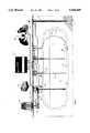
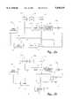
- FIG. 1is a pictorial representation of a system of this invention as applied to an underground gasoline tank.
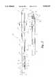
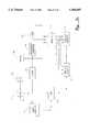
- FIG. 2is a three-dimensional partially cutaway side view of the probe assembly.
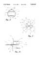
- FIG. 3is a cross-sectional view of the probe body illustrating the position of a calibration rod relative to the longitudinal axis of the probe body.
- FIG. 4is a top view of a preferred embodiment of the bushing assembly used to vertically position the probe body.
- FIG. 4ais a side view of the preferred embodiment of the bushing assembly shown in FIG. 4
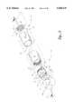
- FIG. 5is an exploded view of a preferred embodiment of the transducer assembly having a back-ranging trap.
- FIG. 6is a cross-sectional view of the preferred embodiment of the transducer assembly shown in FIG. 5.
- FIGS. 7 and 7aare comparative cross-sectional views of a portion of the ultrasonic probe of the prior art compared to this invention illustrating the meniscus effect on the fluid surface as its level crosses a calibration reflector.
- FIG. 8is a representative cross-sectional view of a preferred embodiment of the ultrasonic probe illustrating the positioning of the calibration reflectors within the ultrasonic probe and tank cavity wherein the fluid level is between calibration reflectors R 8 and R 9 .
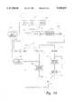
- FIG. 9ais a block diagram illustrating the various operative relationships between the micro-controller, the synchronizer, clock, pulser, transducer, DAC, amplifier, FWR/LPF, and ADC used in making the various possible low resolution fluid volume measurements and determination of the leading edge of the primary echo packet or envelope associated with the fluid surface.
- FIG. 9bis a block diagram illustrating the various preferred operative relationships between the micro-controller, the synchronizer, clock, pulser, transducer, DAC, amplifier, FWR/LPF, timer, and threshold detector used in making the various possible fluid volume measurements.
- FIG. 9cis a block diagram illustrating the various preferred operative relationships between the micro-controller, the synchronizer, clock, pulser, transducer, DAC, amplifier, timer, inverter threshold detector and zero-crossing detector used in making the fluid leak detection measurements.
- FIG. 9dis a block diagram illustrating the preferred composite operative relationship between the various electronic circuits to make the fluid volume and leak detection measurements.
- FIG. 10is an example of the visual image of the primary and secondary echo envelopes that is obtained when the attentuator has been set to produce an output signal from the amplifier having minimum signal strength.
- FIG. 11is an example of the visual image of the primary and secondary echo envelopes that is obtained when the attentuator has been set to produce an output signal from the amplifier having a greater signal strength.
- FIG. 12is a graphical representation of the primary echo packet signals generated by the transducer and the corresponding echo envelope signals generated with the primary echo packet signals have been effected by the FWR/LPF.
- FIG. 13is a graphical representation of the changes to an echo packet of ultrasonic signals reflected from a surface to form a corresponding envelope of fully rectified, filtered signals.
- FIG. 14is an illustration of the profile obtained from measuring the gasoline/water interface below the transducer when the primary echo envelope associated with the water surface is imbedded in the primary echo envelope associated with the tank bottom.
- FIG. 15is an illustration of the profile obtained from measuring the gasoline/water interface below the transducer when the primary echo envelopes associated with the water surface and the tank bottom can be clearly distinguished.
- FIG. 16is an illustration of the profile obtained from measuring the gasoline/water interface below the transducer when the primary echo envelope associated with the water surface is imbedded in the firing pulse envelope.
- the preferred embodiments of the ultrasonic probe and the ultrasonic precision testing systemare described in conjunction with measuring fluid levels and leakage rates in underground gasoline tanks of a typical retail gasoline station.
- FIG. 1a pictorial schematic diagram of a typical double wall underground gasoline tank 1 of known dimensions is illustrated having various fluid level and leak detection monitoring devices electronically interfaced to a microprocessor forming part of a site operating controller 2. More particularly, the area around tank 1 is provided with monitor well sensors 3 which are used to detect the presence of gasoline in the tank bed 4. In addition, interstitial sensors 5 are placed between the double walls 6 of tank 1 to detect the presence of water which has leaked from tank bed 4 into inner wall cavity 8, or gasoline which has leaked from the primary tank cavity 7 into the inner wall cavity 8. It is also preferred that dispenser sump sensors 9 are positioned in the sump 10 beneath the gasoline dispensers 11 to detect the presence of water or gasoline which has leaked into sump 10.
- pump sump sensors 12are positioned in sumps 13 in which submersible pumps 14 are positioned.
- Pump sump sensors 12are used to detect the presence of water or gasoline which may have leaked into sump 13.
- pressure sensorsbe installed in the line 15 that convey the gasoline from primary tank cavity 7 to gasoline dispensers 11 to monitor the pressure in these lines for the purpose of line leak detection.
- ultrasonic probe 16which is used to measure the gasoline and/or water level in primary tank cavity 7, as well as to determine the gasoline leakage from primary tank cavity 7.
- the various sensors and ultrasonic probe 16are electronically interfaced with site operating controller 2.
- Keyboard 17 and CRT monitor 18are operatively connected to site operating controller 2 to permit the display of data obtained from the various sensors and ultrasonic probe 16. Additional information relating to inventory control and sales can also be automatically monitored by a point-of-sale register 19 electronically interfaced with site operating controller 2.
- Probe 16comprises an elongated, hollow probe body 20 having a top end 21 to which a bushing assembly 22 for holding probe body 20 in a vertical position within primary tank cavity 7 is attached, and having a bottom end 23 to which a transducer assembly 24 is attached. Additionally, probe 16 comprises a series of calibration reflectors 25 which extend in a plane that is perpendicular to the longitudinal axis 26 of probe body 20, and which are positioned in the plane so as to be offset from longitudinal axis 26.
- the calibration reflectors 25are vertically separated to produce primary echo packets of reflected ultrasonic sound waves having approximately equal peak strength when detected by transducer assembly 24. It is more preferred that the peak strength of the primary echo packet from the gasoline surface be at least three, and more preferably five, times greater than the peak strength of the primary echo packets from the calibration reflectors 25.
- the primary echo packetsstrike transducer assembly 24 and are reflected back to calibration reflectors 25 which in turn are reflected back toward transducer assembly 24 as secondary echo packets. It is still more preferred that calibration reflectors 25 be positioned so that the detection of secondary echo packets resulting from activation of transducer assembly 24 be slightly delayed with respect to the detection of a primary echo packet from a different calibration reflector so as to embed the secondary echo packets in the trailing edge of a primary echo packet.
- all calibration reflectors 25be offset from longitudinal axis 26 so as to minimize the fluid level signal loss associated with the surface distortion cause by the effect of the meniscus as illustrated in FIG. 7.
- calibration reflectors 25to achieve these effects will vary depending on the diameter of probe body 20, the size and shape of the calibration reflectors 25, the frequencies of the sound waves, and the fluid contained in the tank cavity 8.
- cylindrical probe body 20It is preferred for cylindrical probe body 20 to have an inside diameter of approximately two inches, that calibration reflectors which are constructed from metal rods should be spaced apart approximately seven and quarter inches and offset from longitudinal axis 26 approximately 1/2 inch. It is more preferred that at least those calibration reflectors positioned in the lower half of tank cavity 8 be separated from adjacent calibration reflectors by progressively smaller distances, as well as alternately offset on opposite sides of the longitudinal axis 26. For example, as shown in FIG. 8, the distance between calibration reflectors R 1 and R 2 will be different from distance between calibration reflectors R 2 and R 3 .
- probe body 20will be constructed with pairs of aligned openings 27 through which the opposite ends of calibration reflectors 25 can extend and be fixed in pre-determined positions such as by gluing or other conventional securing methods.
- transducer assembly 24is positioned so that its piezoelectric crystal will be approximately 8 inches from the bottom of the tank cavity. Then the calibrations reflectors, R 1 through R 11 , will be positioned in increasing distances from the piezoelectric crystal.
- the distance between the piezoelectric crystal and R 1is 8.0"
- the distance between successive calibration reflectors, starting with the distance between R 1 and R 2is set to be 7.8", 7.6", 7.4", 7.2", 7.0", 8.0", 7.8", 7.6", 7.4", and 7.2", respectively
- Probe body 20will preferably be constructed from a material having poor thermal conductivity and which is rigid enough to maintain the position of the transducer assembly 24 relative to the calibration reflectors 25.
- a preferred materialis fiberglass.
- Probe body 20will be of sufficient length to permit top end 21 to extend above the surface of the gasoline in primary tank cavity 7 while allowing bottom end 23 to extend to the floor 28 which along with inner side walls 29 form primary tank cavity 7.
- Probe body 20will also be provided with at least one opening 30 positioned above transducer assembly 24 to permit the fluids in primary tank cavity 7 to flow into passageway 31 of probe body 20 at a position above transducer assembly 24.
- a second opening 32is located below bushing assembly 22 to permit the pressure inside passageway 31 to equalize with the pressure inside primary tank cavity 7. This will result in the gasoline level in passageway 31 being the same as in cavity 7.
- passageway 31be of relatively uniform cross-section and that its cross-section be sized to permit the fluid inside passageway 31 to form a substantially flat surface to avoid any significant effect from the meniscus formed by the gasoline on the probe's interior walls at the gasoline surface level.
- the preferred cross-section configurationalis a circular cross-section no greater than 2 inches in diameter.
- the actual configurationwould depend on the viscosity of the fluid and the material from which the inner walls 32 forming passageway 31 are constructed, as well as other known factors.
- Bushing assembly 22should be designed to vertically align and hold probe body 20 whereby its longitudinal axis 26 is substantially perpendicular to the fluid surface.
- the actual designwill be dependent upon the construction of tank 1 and the access opening 33 provided for probe body 20 to extend down into cavity 7.
- the designwill also be dependent upon whether the probe body 20 will be part of a permanent construction that would be more typical of a leak detection or inventory monitoring system, or part of a portable leak detection measurement system.
- Bushing assembly 22 illustrated in FIGS. 2 and 4is a preferred embodiment for use in a permanent leak detection or inventory monitoring system.
- bushing assembly 22comprises bushing 34 sized and shaped to fit through the top end 21 of probe body 20 and into passageway 31.
- Bushing 34is preferably provided with its own passageway 35 formed by wall surfaces 36 extending concentric to the longitudinal axis 37 of bushing 34.
- axis 37 and axis 26are aligned with one another.
- a flexible member 38Positioned on top of bushing 34 is a flexible member 38 that extends perpendicular from bushing 34 and is sized to contact the side walls 36 forming tank opening 33. Member 38 is held in position by rigid plate 39 and screws 40 as shown in FIGS. 2 and 4.
- Bushing assembly 22also comprises a BNC connector 41 which extends perpendicularly from plate 39. Operatively connected to BNC connector 41 is electrical cable 42 extending downward through member 38 and into passageway 35.
- a cable guideway 43 formed by wall 44extends parallel to axis 26 along the exterior of probe body 20. In an alternate embodiment cable guideway 43 could be formed along the interior of probe body 20.
- An opening 45is provided in probe body 20 which connects passageway 31 to cable guideway 43 to permit cable 42 to extend into guideway 43. Cable guideway 43 preferably extends along the exterior of probe body 20 at least to a position adjacent transducer assembly 24.
- Bushing assembly 22may also comprise bail 46 which is attached at its lower ends 47 to bushing 34 and extends through member 38 and plate 39 to form a loop above plate 39 that can be used to lower probe body 20 into cavity 7.
- Bushing 34is fixed to probe body 20 preferably by screws 48 or other known means to allow the bushing assembly 22 to be removed for repair.
- member 38is constructed of two rubber pieces 49 and 50, each piece having a pair of protruding ears 51 and 52, respectively.
- Ears 51 and 52extend outward to contact and apply sufficient pressure against wall surface 100 to hold probe body 20 in a vertical position in cavity 7.
- Ears 51 and 52are preferably constructed from material of sufficient flexibility to allow them to bend as they press against wall surface 36 while probe body 20 is being lowered into cavity 7.
- transducer assembly 24is attached at the bottom end 23 of ultrasonic probe 16. This attachment can be by any conventional means such as screws 53 which extend through probe body 20 and transducer tubing member 54 forming part of transducer assembly 24. Probe body 20 is also provided with an opening 55 through its exterior wall positioned above transducer assembly 24 to permit cable 42 to extend from cable guideway 43 back into passageway 31 via opening 79 in transducer body 60 where it can then be operatively connected to transducer assembly 24 as described below.
- transducer tubing member 54Attached to transducer tubing member 54 is a transducer 56 which serves as both an ultrasonic pulse transmitter and an ultrasonic pulse receiver.
- a preferred means of attaching transducer 56 to tubing member 54is to construct tubing member 54 with an interior threaded wall 57 at one end 58 to matingly receive the exterior threaded end 59 of transducer body 60.
- transducer body 60The opposite end 61 of transducer body 60 is provided with a cavity 62 into which are fixedly fitted a damper ring 63, a piezoelectric crystal 64, and a cover 65 Electrical wires 66 are fixed to crystal 64 and extend through a notch 74 cut in damper ring 63 and further extend through wire passageways 75 and 76 in transducer body 60 to operably connect to resistor 67.
- any cavitybe filled with a potting compound to provide for a smooth surface and to isolate the leads from the fluid. It is also preferable that a wall surface 77 which is indented from wall surface 73 be provided for damper ring 63 to be fixedly positioned.
- Wall surface 77can also be provided for a second indentation cavity 78 to permit electrical wires 66 to be bent and extend into wire passageways 75 and 76.
- Coaxial cable 42which passes through one of the oppositely positioned openings 79 is operatively connected to resistor 67 via one of its leads 68.
- transducer 56be constructed to provide maximum energy transfer to the gasoline in the upward direction of travel while providing the means to control the strength of the back ranging signal.
- the desired energy transfercan be achieved if transducer body 60 is shaped so that its lower end 69 facing tank cavity floor 28 has a flat top wall surface 70 which with outwardly tapering side wall surfaces 71 form a partial cone-shaped interior cavity 72.
- the strength of the backgoing ultrasonic pulsescan be controlled by the shape of cavity 72, the shape of transducer body 60, and the amount of contact area between crystal 64 and transducer body 60; i.e., the size of wall surface 73.
- the slope of side wall surfaces 71is selected to trap and internally dissipate any sound waves emanating from crystal 64 and not impinging flat surface 70.
- the cross-sectional area of the flat top wall surface 70 and contact surface between crystal 64 and wall surface 73can be varied to optimize the strength of the ultrasonic pulse reflection from the gasoline/water interface located below transducer body 60.
- a preferred sound wave dampening meansis back-ranging trap assembly 80 which comprises back-ranging trap 81 fixed to one end of tubing 82.
- Tubing 82is fixed connected to tube 54 in passageway 31 by screws, glue, or any other common attaching means.
- Tubing 82is preferably of the same diameter as transducer tubing member 54 to permit the two to abut one another when positioned in probe body 20.
- Tubing 82has a length which preferably extends a fixed distance from bottom edge 83 of probe body bottom end 23 when it is inserted into passageway 31 and abuts against transducer tubing member 54.
- tubing 82 and tubing member 54may be one piece.
- Probe body 20will be provided with slots 84 extending from bottom edge 83 a sufficient distance to allow the fluid in tank cavity 7 to enter probe body 20 at a position above back-ranging trap 81.
- tubing 82is provided with an interior threaded end 85 to permit exterior threaded end 86 of back-ranging trap 81 to be fixed into position within tubing 82.
- Back-ranging trap 81is provided with one or more passageways 87 extending through opposite sides 88 and 89 of back-ranging trap 81 to permit installation and removal of trap 81.
- Aligned openings 92are provided in tubing 82 which align with slots 84 at a position between cavity 72 and back-ranging trap 81 to permit fluid to flow into chamber 90.
- Side 89is constructed whereby its surface is formed by a series of concentric ridges 91 and a flat back ranging target 93. This construction provides for further means to control the strength of the bottom reflection of ultrasonic waves reflected back to transducer 56.
- the difference in area of the water/gasoline interface and the back ranging target 93 on the trap 81provides the means to discriminate between the tank bottom and water/gasoline interface.
- back-ranging trap 81be constructed from material that is stable in gasoline and water, yet possesses sound dampening characteristics. Suitable material would include various known rubber compounds, as well as other metal or non-metal materials having similar sound dampening characteristics. The shape of side 89 could also be varied to form other configurations which are known to trap sound waves.
- FIGS. 9a-9dare block diagrams of the electronic circuitry used with the ultrasonic probe 16 to form ultrasonic ranging systems that can be used to determine fluid volume in tank 1, to determine the leakage rate from tank 1, and/or to monitor the inventory of fluid flowing into and out of tank 1. This information is provided via measurements of the time of flight (TOF) of the leading edge of the echo packets or echo envelopes associated with the fluid surface and/or certain specified calibration reflectors 25.
- TOFtime of flight
- transducer 104, attentuator 105, amplifier 106, FWR/LPF 107, and ADC 112are operatively connected to permit the electrical signals generated by transducer 104 to be amplitude adjusted by attentuator 105 and amplifier 106, before rectification and filtering by FWR/LPF 107 to form the primary echo envelope signals which are then digitized by ADC 112 prior to storage and/or analysis of the digitized signals by micro-controller 100.
- the TOF measurements for fluid volume determinationsbe made utilizing threshold detector 108 to scan the electrical signals from FWR/LPF 107 upon receipt of a scanning signal from micro-controller 100 to detect an electrical signal greater than a selected threshold voltage signal, and to signal timer 109 to stop upon detection of the electrical signal.
- the amplitude adjusted signal from attentuator 105/amplifier 106may be inverted by inverter 113 when V 3 has been set at a level greater than or approximately equal to the maximum peak of the first half cycle of the primary echo packet being examined.
- micro-controller 100provides through its software the means to configure the electronics to obtain the desired measurements. Further, micro-controller 100 is used to send control signals to various electronic parts in the circuit and to receive and process the time and signal strength data generated by various parts of the electronic circuitry to obtain the TOF measurements and calculate the fluid volume or the fluid leakage from tank cavity 8.
- micro-controller 100configures the ultrasonic ranging system as per the resolution measurement to be made. It then transmits a start signal to synchronizer 101 which is electronically connected to clock 102 in a manner to cause synchronizer 101 to send a firing signal to pulser 103 when synchronizer 101 detects a rising edge of a cycle from the signals transmitted by clock 102 which is also being transmitted to pulser 103. Upon detection of the rising edge, synchronizer 101 also simultaneously transmits a start signal to timer 109, as well as transmits a start signal to micro-controller to signal ADC 112 to begin digitizing any electrical signals which it may receive. Specific electronic circuitry which can perform this function is well known in the art.
- transducer 104Upon receipt of the firing signal from synchronizer pulser 103 transmits an electronic signal to transducer 104, which cause the crystal in transducer 104 to oscillate. This oscillation produces a packet of sinusoidal ultrasonic sound waves which are radiated from both sides of the transducer crystal. This packet of ultrasonic sound waves travel up probe body passageway 31 striking each of the calibration reflectors 25 and the fluid surface, and downward in chamber 90 striking the water surface and back-ranging trap 81 (or tank bottom when no back-ranging trap is used). As the transmitted wave encounters calibration reflectors 25 and/or the fluid surfaces some portion of the ultrasonic wave is reflected, and the corresponding echo packet is reflected back toward transducer 104. These echo packets are referred to as the primary echo packets.
- the primary echo packets from each of these surfaceswill strike transducer 104 and again reflected back through passageway 31 or chamber 90. These packets will strike the same surfaces and will be reflected back to the transducer 104 a second time. These reflected primary echo packets are referred to as secondary echo packets.
- a second type of secondary echo packetis created when the original echo packet from the transducer 104 first strikes the fluid surface and is then reflected from a calibration reflector back to the fluid surface and finally back to transducer 104. Because only a portion of the primary echo packet is reflected back a second time, the amplitude or strength of the sound waves in these secondary echo packets is diminished, but still detectable by transducer 104.
- the sound wave form of a typical echo packetis converted by the transducer 104 into a corresponding series of electrical signals (See top half of FIG. 12).
- the specific electronic circuitry which will cause the transducer crystal to oscillate at the desired ultrasonic frequency to produce ultrasonic waves, and to convert the reflected sound waves to corresponding electrical signalsis well known in the art.
- Low Resolution Measurement of Fluid VolumeLow resolution measurements are made to identify the echo packets associated with the fluid surface, the water surface, the tank bottom, and the calibration reflectors so as to be able to set the enabling and disabling timing gates on the threshold detectors 108 or 110 which is necessary in the medium and high resolution measurements.
- tank volume measurementsthat do not need the high degree of accuracy obtained by the medium and high resolution measurement methods. For these situations the low resolution measurements can be used without further processing.
- the electrical signals generated by transducer 104can be transmitted directly to (1) ADC 112, (2) to DAC 105, or (3) to FWR/LPF 107.
- the electrical signalswill ultimately be digitized by the ADC 112 in order for the signals to be analyzed by micro-controller 100 for the purpose of establishing the location of the leading edge of the primary echo envelopes.
- electrical signals from transducer 104are fed directly to ADC 112 to form corresponding digitized signals.
- the digitized electrical signalshave been digitized into a specific number of bins wherein each bin represents the voltage level in a pre-set time period. For a 500 KHz digitization rate clock, each bin will represent the voltage level in a particular 2 ⁇ sec time period.
- the digitized signalis then scanned by micro-controller 100 to identify the first bin, B fs , having a digitized signal greater than a pre-determined signal threshold voltage V 1 .
- V 1is selected to be less than the peak voltage in the primary echo packet associated with the fluid surface, but greater than the peak voltage in the primary echo packet associated with any of the calibration reflectors.
- bin B fsidentifies the leading edge of the echo packet associated with the fluid surface and can be used to calculate in a known manner the TOF of the sound waves from transducer 104 to the fluid surface, and in turn calculate the fluid level using a given speed of sound in the fluid. From this calculation one can then use the calculated fluid level and the known geometry of tank cavity 8 to calculate in a known manner the fluid volume.
- the electrical signals from transducer 104are amplitude adjusted by first being attenuated by DAC 105 in an amount set by the micro-controller 100 and/or then amplified by a fixed amount by amplifier 106.
- the output of attentuator 105is considered to correspond to an amplitude gain of 1.
- the amount of amplitude adjustmentis preferably set so that the peak voltage associated with the fluid level echo packet will be in the upper range of the voltage scale being recorded by the electronic circuitry. This is typically about 5 volts.
- These adjusted electrical signalsare then digitized by ADC 112 and scanned by micro-controller 100 to identify first bin B fs having a digitized signal greater than the pre-determined signal strength threshold V 1 .
- the fluid volumecan then be calculated as described above.
- the electrical signals from transducer 104are first rectified and filtered by FWR/LPF 107 to form echo envelopes associated with the echo packets. These rectified/filtered signals are then fed to ADC 112 to produce corresponding digitized signals. As in each of the other two methods described these bins containing the digitized signals are scanned by micro-controller 100 to identify first bin B fs having a digitized signal greater than the pre-determined signal strength threshold V 1 . The fluid volume can then be calculated as before.
- programmable attenuator 105such as an eight bit digital-to-analog converter (DAC), and a fixed gain amplifier 106 provide the means to control the amplitude or strength of the electrical signals from transducer 104.
- DACdigital-to-analog converter
- a fixed gain amplifier 106provide the means to control the amplitude or strength of the electrical signals from transducer 104.
- DAC0830 DACNational Semiconductor Model DAC0830 DAC and an amplifier with a gain of 60
- the overall adjustment to the amplitude or strength of the electrical signalsis determined by:
- Nis an integer in the range 0 to 255 and represents one of the possible setting of the 8 bit DAC.
- This DACprovides the wide range of control of the signal strength at the output of the amplifier 106 to obtain the desired signal discrimination between the primary echo packets.
- the preferred low resolution measurementsare made by first amplitude adjusting the electrical signals from transducer 104 through the use of DAC 105 and amplifier 106.
- the electrical signals adjusted for maximum attenuationare then rectified and filtered by FWR/LPF 107 before being digitized by ADC 112.
- the attenuated, rectified, filtered and digitized electrical signalsare then scanned by micro-processor 100 to identify the bin B fs having a signal greater threshold voltage V 1 .
- the volume measurementis then calculated as explained above.
- the fluid surfaceis clearly shown as located between calibration reflectors R s .
- the calibration reflectors 25be offset with respect to longitudinal axis 26 (See FIG. 8), and be vertically unequally spaced to provide a fluid interface echo strength to calibration reflector echo strength ratio of the order of 3 to 1, preferably 5 to 1.
- the amount of the vertical differences in spacing between the calibration reflectorsshould be set so that the secondary echo packet of a particular calibration reflector will be imbedded in the trailing edge of another calibration reflector. This positioning insures that the secondary echo envelopes do not interfere with the detection of the leading edge of the primary echo envelopes associated with calibration reflectors 25.
- FIGS. 12 and 13illustrate the changes made to the electrical signal from the transducer 104 to produce the primary echo envelope images shown in FIG. 10. More particularly, the top section of FIG. 12 illustrates a typical sinsoidual electrical signal generated by transducer 104 in a probe having four reflection reflectors. For purposes of simplicity, background noise and the effect of secondary echo packets are not shown. The bottom section of FIG. 12 represents the rectified and filtered electrical signal corresponding to the top section of FIG. 12. FIG. 13 illustrates the transformation an individual primary echo packet goes through during attenuation, rectification and filtration to form a primary echo envelope.
- the low resolution measurement methodcan be used to determine the approximate leading edge of the primary echo packets or primary echo envelopes associated with the fluid surface. It is now necessary to determine the approximate leading edge of at least the two submerged calibration reflectors nearest the fluid surface, and more preferably of each of the submerged calibration reflectors 25.
- the amount of attenuation by attentuator 105is decreased, and a second firing of transducer 104 is made to generate a second set of electrical signals that are attenuated, rectified, filtered, and digitized in a similar manner as before to produce a series of primary echo envelopes such as seen in FIG. 11.
- the amount of amplitude adjustment by attentuator 105 and amplifier 106is set so that the peak voltage in each of the primary echo packets associated with the submerged calibration reflectors approaches a given voltage above which has been clipped by the electronics of the system. Typically the signals are electronically clipped at 5 volts in this measurement. From the known B fs in the low resolution measurement, one can identify which primary echo envelope is associated with the fluid surface and know which primary echo envelopes are associated with the submerged calibration reflectors.
- the digitized electrical signals from the second set of electrical signalsare scanned by micro-controller 100 to locate the first bin in each primary echo envelope associated with the submerged calibration reflectors.
- the first binis defined as the first bin in the primary echo packet greater than a second pre-determined threshold voltage, V 2 , which may be different from V 1 .
- scanningis continued for at least three bins after the first detected bin having a voltage signal greater than V 2 to ensure that the first detected signal was not associated with an extraneous noise spike.
- Electronic circuitrywhich can provide such scanning is well known.
- This informationis stored in micro-processor 100 and will be used to send enabling signals to threshold detector to enable threshold detector 108 to search for and identify electrical signals greater than a third threshold voltage V 3 , which may be different from either V 1 or V 2 .
- one of the two submerged calibration reflectors(e.g., R 7 ) identified from the data received in the low resolution measurement step is selected.
- Micro-controller 100signals timer 109 to reset itself to zero. Once timer 109 has been reset, the micro-controller 100 signals the synchronizer 101 to transmit a firing signal upon synchronization with the rising edge of a clock cycle to pulser 103, as well as to signal the start of timer 109. The pulser is fired and transducer 104 transmits the ultrasonic sound waves toward the various surfaces.
- Micro-processor 100has operatively decreased the amount of attenuation which attentuator 105 will effect on the electrical signals received from transducer 104.
- the adjusted electrical signalsare rectified and filtered by FWR/LPF 107 to produce the series of primary echo envelopes. More preferably, as seen in FIG. 11, the amount of attenuation will be set so that the anticipated peak strength signals in the primary echo envelopes associated with each of the submerged calibration reflectors will be approximately 5 volts.
- micro-processor 100Prior to the known estimated time when the leading edge of the primary echo packet from the selected calibration reflector should be detected by threshold detector 108, micro-processor 100, utilizing the bin information which it has stored, signals threshold detector 108 to begin scanning for a voltage greater than voltage threshold, V 3 . When threshold detector 108 observes a signal greater than threshold voltage V 3 , it signals timer 109 to stop. Micro-processor 100 reads and stores this time. These steps are repeated for the other submerged calibration reflector, R 6 . For future reference, these steps could be repeated for all of the calibration reflectors, R 1 through R 11 in order to adjust by various known formulae the volume measurements to a standard temperature in order to obtain a temperature referenced corrected volume of the fluid in tank cavity 8.
- the leading edge associated with the fluid surface FSbe determined by first decreasing the attenuation on attentuator 105 to a level to again be able to reproduce a signal similar to that seen in FIG. 10.
- Transducer 104is again fired, and prior to the known estimated time when the leading edge of the primary echo packet associated with the fluid surface should be detected by threshold detector 108, micro-controller 100 utilizing the TOF information which it has stored, signals threshold detector 108 to begin scanning for a voltage threshold in the same range of magnitude as V 2 .
- threshold detectordetects such a signal, it signals timer 109 to stop.
- Micro-processor 100reads and stores this time which will be used as the TOF associated with the leading edge of fluid level, FS.
- threshold detector 108is enabled to begin scanning at three bins (6 ⁇ secs) before the anticipated detection of the leading edge, and is disabled after detection of the leading edge. This insures that the echo envelope from an adjacent calibration reflector 25 does not interfere with the detection of the desired echo envelope.
- timer 109Upon identification of a signal above the threshold voltage V 2 , timer 109 is stopped and subsequently the threshold detection circuitry is disabled.
- This third pre-determined voltage threshold V 3will be set high enough to be well above the background noise and yet low enough to detect all of the primary echo envelopes of the calibration reflectors and the fluid surface.
- Each of the three bins so identifiedare selected to represent the TOF of the leading edge of the primary echo packets of the fluid surface and the two submerged calibration reflectors nearest the fluid surface.
- D fsthe distance from the tank bottom to the fluid surface, D fs .
- D sthe known distance of the submerged calibration reflector closest to the fluid surface from the transducer
- D 7is the known distance of the submerged calibration reflector next closest to the fluid surface from the transducer
- D tis the known distance from the tank bottom to the top of the transducer crystal
- T fsis the determined TOF associated with the fluid surface
- T sis the determined TOF associated with the submerged calibration reflector closest to the fluid surface
- T 7is the determined TOF associated with the submerged calibration reflector next closest to the fluid surface.
- This methodtakes into consideration the changes in velocity of sound in the liquid due to temperature or other factors, and because of the large number of calibration reflectors preferably used, provides an accurate measurement of the fluid volume in the tank cavity 8.
- the depth of the water, D wscan be determined via the use of one of three equations, or weighted combinations of these three.
- the primary echo envelope from the tank bottomoverlaps with the primary echo envelope from the water surface and of the two timings, T b and T ws , only T ws , is measured.
- the depth of the water, D wscan be determined by the following formula:
- T wsis the TOF of the leading edge of the primary echo envelope associated with the water surface
- T r1is the TOF of the leading edge of the primary echo envelope associated with the first calibration reflector
- D bis the known distance from the tank bottom to the bottom of the transducer crystal.
- T b and T wscan be made to both.
- D wscan then be determined by either the above formula or the following formula:
- T bis the measured TOF of the leading edge of the primary echo envelope associated with the tank bottom
- T wsis the measured TOF of the leading edge of the primary echo envelope associated with the water surface
- S wis the known speed of sound in water.
- the water surface primary echo envelopebecomes imbedded in the trailing edge of the transducer firing pulse (See FIG. 16), and T ws is no longer measurable.
- the water levelis given by:
- the primary echo envelope profiles depicted in FIGS. 14 and 16are similar. However, they can be distinguished by the magnitude of their signal strengths.
- the primary echo envelope associated with the tank bottomcan be diminished sufficiently by the use of the back ranging trap assembly 80.
- micro-controller 100has stored in its memory the estimated times of detection of the primary echo packets from each of the calibration reflectors, R 1 through R 11 , and fluid level FS.
- timer 109is started by the signal from synchronizer 101 at the same time that pulser 103 receives its firing signal.
- the electrical signals associated with the sound waves detected by transducer 104are amplitude adjusted by DAC 105 and amplifier 106.
- the adjusted signalsare preferably electronically transmitted to inverter 114 wherein they may be inverted. Inversion of the adjusted electrical signals provides the means for minimizing cycle skipping when threshold detector 110 is searching for a threshold voltage greater than V 3 .
- Micro-controller 100enables threshold detector 109 to begin scanning for a voltage greater than V, just before the time that the particular primary echo packet is estimated to be detected. Preferably, threshold detector 109 will be enabled about 6 ⁇ sec before arrival of the leading edge. Upon detection of such a voltage, threshold detector 100 enables zero crossing detector 111 to begin scanning the adjusted electrical signal for the next zero voltage reading. When the next zero crossing is observed, zero crossing detector 111, through multiplexer 113, signals timer 109 to stop timing. The micro-controller 100 reads and stores the time from the timer 109. This procedure is repeated for the two submerged calibration reflectors nearest the fluid level, and preferably for each of the submerged calibration reflectors in order to make temperature referenced corrected fluid volume measurements.
- the fluid level, and in turn the fluid volumecan be calculated as in the medium resolution measurement method. If this procedure is repeated over time, the leakage rate of the fluid from tank cavity 8 can be measured. Leak detection is carried out during a period of time when no fluid is being dispensed from the tank cavity 8. In the calculation of leak detection, the measured fluid volume will be calibrated for a given temperature, generally 68° F., through use of known formulae from the measured TOFs to each of the submerged calibration reflectors.
Landscapes
- Physics & Mathematics (AREA)
- General Physics & Mathematics (AREA)
- Engineering & Computer Science (AREA)
- Remote Sensing (AREA)
- Computer Networks & Wireless Communication (AREA)
- Radar, Positioning & Navigation (AREA)
- Fluid Mechanics (AREA)
- Electromagnetism (AREA)
- Thermal Sciences (AREA)
- Acoustics & Sound (AREA)
- Measurement Of Levels Of Liquids Or Fluent Solid Materials (AREA)
- Investigating Or Analyzing Materials By The Use Of Ultrasonic Waves (AREA)
- Examining Or Testing Airtightness (AREA)
- Geophysics And Detection Of Objects (AREA)
Abstract
Description
ADJUSTMENT=(60×N)/256
D.sub.ws =D.sub.r1 ×(T.sub.ws /T.sub.r1)+D.sub.b
D.sub.ws =(T.sub.b -T.sub.ws)/2S.sub.w
D.sub.ws =[D.sub.r1 (T.sub.b /T.sub.r1)-D.sub.b]/[S.sub.w T.sub.r1 /D.sub.r1 -1].
Claims (22)
Priority Applications (9)
| Application Number | Priority Date | Filing Date | Title |
|---|---|---|---|
| US08/307,292US5568449A (en) | 1994-09-02 | 1994-09-02 | Methods and apparatus for use in ultrasonic ranging |
| TW084109096ATW308639B (en) | 1994-09-02 | 1995-08-31 | |
| AU35437/95AAU3543795A (en) | 1994-09-02 | 1995-09-01 | Electronic circuitry used in ultrasonic ranging systems employed in monitoring fluid in tanks |
| PCT/US1995/011175WO1996007875A1 (en) | 1994-09-02 | 1995-09-01 | Ultrasonic probes for use in monitoring fluid in tanks |
| AU35028/95AAU3502895A (en) | 1994-09-02 | 1995-09-01 | Ultrasonic probes for use in monitoring fluid in tanks |
| PCT/US1995/011143WO1996007933A1 (en) | 1994-09-02 | 1995-09-01 | Ultrasonic methods used to monitor fluid in tanks |
| AU34635/95AAU3463595A (en) | 1994-09-02 | 1995-09-01 | Ultrasonic methods used to monitor fluid in tanks |
| PCT/US1995/011144WO1996007934A1 (en) | 1994-09-02 | 1995-09-01 | Electronic circuitry used in ultrasonic ranging systems employed in monitoring fluid in tanks |
| UY24029AUY24029A1 (en) | 1994-09-02 | 1995-09-04 | METHODS AND APPARATUS TO USE IN ULTRASONIC TELEMETRY |
Applications Claiming Priority (1)
| Application Number | Priority Date | Filing Date | Title |
|---|---|---|---|
| US08/307,292US5568449A (en) | 1994-09-02 | 1994-09-02 | Methods and apparatus for use in ultrasonic ranging |
Publications (1)
| Publication Number | Publication Date |
|---|---|
| US5568449Atrue US5568449A (en) | 1996-10-22 |
Family
ID=23189087
Family Applications (1)
| Application Number | Title | Priority Date | Filing Date |
|---|---|---|---|
| US08/307,292Expired - Fee RelatedUS5568449A (en) | 1994-09-02 | 1994-09-02 | Methods and apparatus for use in ultrasonic ranging |
Country Status (5)
| Country | Link |
|---|---|
| US (1) | US5568449A (en) |
| AU (3) | AU3543795A (en) |
| TW (1) | TW308639B (en) |
| UY (1) | UY24029A1 (en) |
| WO (3) | WO1996007934A1 (en) |
Cited By (27)
| Publication number | Priority date | Publication date | Assignee | Title |
|---|---|---|---|---|
| EP0946887A4 (en)* | 1996-12-13 | 2000-10-11 | Solid Scient Research And Dev | Method and device for ultrasonic ranging |
| US6323441B1 (en)* | 2000-03-10 | 2001-11-27 | Honeywell International Inc. | Ultrasonic distance measuring system for monitoring railroad car loads |
| US6662648B2 (en)* | 2000-09-06 | 2003-12-16 | Vega Grieshaber Kg | Filling level measuring device |
| US20030230593A1 (en)* | 2002-06-18 | 2003-12-18 | Hutchinson Ray J. | Service station leak detection and recovery system |
| US20040035208A1 (en)* | 2002-08-21 | 2004-02-26 | Diaz Aaron A. | Acoustic inspection device |
| US20040035188A1 (en)* | 2000-08-31 | 2004-02-26 | Robert Bridges | Method of testing the pressure integrity of a tank |
| US6729797B2 (en) | 2001-08-15 | 2004-05-04 | Delaware Capital Formation, Inc. | Testable sump apparatus |
| US20040144171A1 (en)* | 2001-03-01 | 2004-07-29 | Adgie Glyn Martin | Apparatus and method of fluid level measurement |
| EP1460396A1 (en) | 2003-03-06 | 2004-09-22 | Robert Seuffer GmbH & Co. KG | Method and device for ultrasonic level sensing of a liquid in a container |
| US20060169055A1 (en)* | 2005-01-06 | 2006-08-03 | Sensotech | Method and system for measuring fluid level in a container |
| WO2006097076A1 (en) | 2005-03-18 | 2006-09-21 | Hella Kgaa Hueck & Co. | Device for measuring the level of a liquid in a container by means of an ultrasonic converter |
| US20060245301A1 (en)* | 2005-04-28 | 2006-11-02 | Wroga Frank C | Electronic sensor which can be communicated with |
| US20080184794A1 (en)* | 2006-03-14 | 2008-08-07 | Hella Kgaa Hueck & Co. | Device for Measuring the Level of a Liquid in a Container With an Ultrasonic Transducer |
| US7421895B1 (en)* | 2005-04-21 | 2008-09-09 | Caldwell Joseph W | Fluid level measuring system |
| US20100207807A1 (en)* | 2009-02-17 | 2010-08-19 | Gk Tech Star, Llc | Level gauge with positive level verifier |
| US20110161037A1 (en)* | 2009-12-29 | 2011-06-30 | Jeff Sutherland | Inline Inspection System and Method for Calibration of Mounted Acoustic Monitoring System |
| US20110161038A1 (en)* | 2009-12-29 | 2011-06-30 | Jeff Sutherland | System and Method for Calibration of Mounted Acoustic Monitoring System with Mapping Unit |
| CN102192771A (en)* | 2010-03-16 | 2011-09-21 | 赫拉胡克公司 | Device for determining a fill level |
| US20110228640A1 (en)* | 2010-03-16 | 2011-09-22 | Holcomb David E | Torsional Ultrasonic Wave Based Level Measurement System |
| WO2012141812A1 (en)* | 2011-04-11 | 2012-10-18 | Schmitt Industries, Inc. | Event monitoring and detection in liquid level monitoring system |
| US20150000396A1 (en)* | 2012-03-16 | 2015-01-01 | Emitec Gesellschaft Fuer Emissionstechnologie Mbh | Delivery unit with fill level sensor for a liquid additive, tank for storing liquid additive, motor vehicle and method for monitoring a fill level |
| US20170122789A1 (en)* | 2014-07-14 | 2017-05-04 | Continental Automotive Gmbh | Method for determining the fill state in a tank |
| US20170335672A1 (en)* | 2015-06-23 | 2017-11-23 | Bauer Spezialtiefbau Gmbh | Measuring device and method for measuring a hole in the ground |
| WO2018002363A1 (en)* | 2016-07-01 | 2018-01-04 | Serviglp, S.L. | Monitoring a product level in a container |
| RU183632U1 (en)* | 2018-06-27 | 2018-09-28 | Общество с ограниченной ответственностью "Л КАРД" | Fuel level sensor |
| CN112730607A (en)* | 2020-12-31 | 2021-04-30 | 青岛精安医疗科技有限责任公司 | Ultrasonic oxygen concentration measuring method and system based on flow detection and oxygen generation system |
| CN113447983A (en)* | 2021-06-23 | 2021-09-28 | 湖南国天电子科技有限公司 | Data acquisition and signal processing method of shallow stratum profiler |
Families Citing this family (6)
| Publication number | Priority date | Publication date | Assignee | Title |
|---|---|---|---|---|
| GB9606151D0 (en)* | 1996-03-23 | 1996-05-29 | Smiths Industries Plc | Fluid-gauging systems and probes |
| DE19648236A1 (en)* | 1996-11-22 | 1998-05-28 | Kathoefer Ets Gmbh | Method and device for determining material properties of liquids |
| EP2040047A1 (en) | 2007-09-20 | 2009-03-25 | Siemens Milltronics Process Instruments Inc. | A multipoint level measurement system |
| CN102136872B (en)* | 2011-03-08 | 2014-03-12 | 袁崇礼 | Ultrasonic carrier information communication system |
| CN108917888A (en)* | 2018-07-04 | 2018-11-30 | 福州金泽科技有限公司 | Intellectual water meter scaling method |
| CN110850417A (en)* | 2019-11-18 | 2020-02-28 | 广东奥迪威传感科技股份有限公司 | Ultrasonic ranging module and ultrasonic ranging equipment |
Citations (33)
| Publication number | Priority date | Publication date | Assignee | Title |
|---|---|---|---|---|
| SU149640A1 (en)* | 1961-12-11 | 1962-11-30 | В.Г. Жувагин | Ultrasonic method for measuring the level of a liquid and a device for its implementation |
| US3113456A (en)* | 1956-06-15 | 1963-12-10 | Acoustica Associates Inc | Liquid volume sensing system |
| US3184969A (en)* | 1963-06-10 | 1965-05-25 | Gen Signal Corp | Liquid level indication system |
| US3214974A (en)* | 1963-12-18 | 1965-11-02 | Altman Lawrence | Remote acoustical sensor |
| US3394589A (en)* | 1965-03-08 | 1968-07-30 | Japan Radio Company Ltd | Apparatus for measuring liquid level |
| US3520186A (en)* | 1968-03-11 | 1970-07-14 | Nat Sonics Corp | Ultrasonic fluid interface sensing |
| US3693445A (en)* | 1970-06-26 | 1972-09-26 | Sven J Johnson | Liquid level measurement device |
| US3745829A (en)* | 1971-10-18 | 1973-07-17 | Electronique Appliquee | Level measuring equipments |
| US3985030A (en)* | 1974-10-29 | 1976-10-12 | William Mcgeoch & Company | Ultrasonic acoustic pulse echo ranging system |
| US4063457A (en)* | 1976-09-27 | 1977-12-20 | Envirotech Corporation | Ultrasonic level sensing device |
| US4084582A (en)* | 1976-03-11 | 1978-04-18 | New York Institute Of Technology | Ultrasonic imaging system |
| US4090407A (en)* | 1977-09-19 | 1978-05-23 | T. W. Salisbury, III | Water level measurement device |
| US4130018A (en)* | 1977-08-30 | 1978-12-19 | Envirotech Corporation | Ultrasonic transducer with reference reflector |
| US4158964A (en)* | 1978-05-10 | 1979-06-26 | The Foxboro Company | Method and apparatus for determining liquid level |
| US4161715A (en)* | 1977-09-02 | 1979-07-17 | Electric Power Research Institute, Inc. | Method and apparatus for measuring the interior dimensions of a hollow body |
| US4170765A (en)* | 1975-04-17 | 1979-10-09 | Marvtek, Corporation | Liquid level sensor |
| US4203324A (en)* | 1977-08-05 | 1980-05-20 | Joseph Baumoel | Sonic liquid level detector |
| US4210969A (en)* | 1978-03-13 | 1980-07-01 | The Stoneleigh Trust | Sonic ranging systems to eliminate errors due to variations in the sound velocity in the medium |
| US4221004A (en)* | 1978-08-03 | 1980-09-02 | Robertshaw Controls Company | Adjustable ultrasonic level measurement device |
| US4229798A (en)* | 1978-01-30 | 1980-10-21 | Alistair Francis McDermott | Liquid storage tank contents gauge |
| US4236144A (en)* | 1977-12-14 | 1980-11-25 | Tokyo Keiso Kabushiki Kaisha | Inspection system for a group of tanks |
| US4241432A (en)* | 1967-04-21 | 1980-12-23 | The United States Of America As Represented By The Secretary Of The Navy | Transducer-reflector system |
| US4320659A (en)* | 1978-02-27 | 1982-03-23 | Panametrics, Inc. | Ultrasonic system for measuring fluid impedance or liquid level |
| US4337656A (en)* | 1979-08-09 | 1982-07-06 | Eugen Rapp | Device for measuring depth and temperature especially for tanks or the like |
| US4361037A (en)* | 1979-11-19 | 1982-11-30 | Vdo Adolf Schindling Ag | Device for electric monitoring of the level of a liquid in a container |
| US4470299A (en)* | 1982-01-04 | 1984-09-11 | Fischer & Porter Company | Ultrasonic liquid level meter |
| US4531406A (en)* | 1982-10-29 | 1985-07-30 | Lockheed Corporation | Ultrasonic liquid quantity measuring apparatus |
| US4578997A (en)* | 1982-01-04 | 1986-04-01 | Fischer & Porter | Time-shaped AGC for ultrasonic liquid level meter of the echo-ranging type |
| US4748846A (en)* | 1982-10-14 | 1988-06-07 | Gilbarco, Inc. | Tank gauging system and methods |
| US4805453A (en)* | 1982-10-14 | 1989-02-21 | Gilbarco, Inc. | Tank sonic gauging system and methods |
| US4811601A (en)* | 1983-10-11 | 1989-03-14 | Tolan Peter J | Method and apparatus for measuring the change in volume with change in temperature of liquid in tanks |
| US4984449A (en)* | 1989-07-03 | 1991-01-15 | Caldwell System Corp. | Ultrasonic liquid level monitoring system |
| US5301549A (en)* | 1992-03-10 | 1994-04-12 | Smiths Industries Public Limited Company | Liquid-level gauging |
Family Cites Families (4)
| Publication number | Priority date | Publication date | Assignee | Title |
|---|---|---|---|---|
| CA1214858A (en)* | 1984-09-27 | 1986-12-02 | Stanley Panton | Acoustic ranging system |
| US4928525A (en)* | 1989-03-02 | 1990-05-29 | Aderholt Gary L | Sonic tank inventory control system and method |
| US5095748A (en)* | 1990-08-06 | 1992-03-17 | Tidel Engineering, Inc. | Sonic tank monitoring system |
| US5335545A (en)* | 1990-09-04 | 1994-08-09 | Magnetrol International, Inc. | Ultrasonic detector with frequency matching |
- 1994
- 1994-09-02USUS08/307,292patent/US5568449A/ennot_activeExpired - Fee Related
- 1995
- 1995-08-31TWTW084109096Apatent/TW308639B/zhactive
- 1995-09-01AUAU35437/95Apatent/AU3543795A/ennot_activeAbandoned
- 1995-09-01WOPCT/US1995/011144patent/WO1996007934A1/enactiveApplication Filing
- 1995-09-01WOPCT/US1995/011143patent/WO1996007933A1/enactiveApplication Filing
- 1995-09-01AUAU35028/95Apatent/AU3502895A/ennot_activeAbandoned
- 1995-09-01WOPCT/US1995/011175patent/WO1996007875A1/enactiveApplication Filing
- 1995-09-01AUAU34635/95Apatent/AU3463595A/ennot_activeAbandoned
- 1995-09-04UYUY24029Apatent/UY24029A1/enunknown
Patent Citations (33)
| Publication number | Priority date | Publication date | Assignee | Title |
|---|---|---|---|---|
| US3113456A (en)* | 1956-06-15 | 1963-12-10 | Acoustica Associates Inc | Liquid volume sensing system |
| SU149640A1 (en)* | 1961-12-11 | 1962-11-30 | В.Г. Жувагин | Ultrasonic method for measuring the level of a liquid and a device for its implementation |
| US3184969A (en)* | 1963-06-10 | 1965-05-25 | Gen Signal Corp | Liquid level indication system |
| US3214974A (en)* | 1963-12-18 | 1965-11-02 | Altman Lawrence | Remote acoustical sensor |
| US3394589A (en)* | 1965-03-08 | 1968-07-30 | Japan Radio Company Ltd | Apparatus for measuring liquid level |
| US4241432A (en)* | 1967-04-21 | 1980-12-23 | The United States Of America As Represented By The Secretary Of The Navy | Transducer-reflector system |
| US3520186A (en)* | 1968-03-11 | 1970-07-14 | Nat Sonics Corp | Ultrasonic fluid interface sensing |
| US3693445A (en)* | 1970-06-26 | 1972-09-26 | Sven J Johnson | Liquid level measurement device |
| US3745829A (en)* | 1971-10-18 | 1973-07-17 | Electronique Appliquee | Level measuring equipments |
| US3985030A (en)* | 1974-10-29 | 1976-10-12 | William Mcgeoch & Company | Ultrasonic acoustic pulse echo ranging system |
| US4170765A (en)* | 1975-04-17 | 1979-10-09 | Marvtek, Corporation | Liquid level sensor |
| US4084582A (en)* | 1976-03-11 | 1978-04-18 | New York Institute Of Technology | Ultrasonic imaging system |
| US4063457A (en)* | 1976-09-27 | 1977-12-20 | Envirotech Corporation | Ultrasonic level sensing device |
| US4203324A (en)* | 1977-08-05 | 1980-05-20 | Joseph Baumoel | Sonic liquid level detector |
| US4130018A (en)* | 1977-08-30 | 1978-12-19 | Envirotech Corporation | Ultrasonic transducer with reference reflector |
| US4161715A (en)* | 1977-09-02 | 1979-07-17 | Electric Power Research Institute, Inc. | Method and apparatus for measuring the interior dimensions of a hollow body |
| US4090407A (en)* | 1977-09-19 | 1978-05-23 | T. W. Salisbury, III | Water level measurement device |
| US4236144A (en)* | 1977-12-14 | 1980-11-25 | Tokyo Keiso Kabushiki Kaisha | Inspection system for a group of tanks |
| US4229798A (en)* | 1978-01-30 | 1980-10-21 | Alistair Francis McDermott | Liquid storage tank contents gauge |
| US4320659A (en)* | 1978-02-27 | 1982-03-23 | Panametrics, Inc. | Ultrasonic system for measuring fluid impedance or liquid level |
| US4210969A (en)* | 1978-03-13 | 1980-07-01 | The Stoneleigh Trust | Sonic ranging systems to eliminate errors due to variations in the sound velocity in the medium |
| US4158964A (en)* | 1978-05-10 | 1979-06-26 | The Foxboro Company | Method and apparatus for determining liquid level |
| US4221004A (en)* | 1978-08-03 | 1980-09-02 | Robertshaw Controls Company | Adjustable ultrasonic level measurement device |
| US4337656A (en)* | 1979-08-09 | 1982-07-06 | Eugen Rapp | Device for measuring depth and temperature especially for tanks or the like |
| US4361037A (en)* | 1979-11-19 | 1982-11-30 | Vdo Adolf Schindling Ag | Device for electric monitoring of the level of a liquid in a container |
| US4470299A (en)* | 1982-01-04 | 1984-09-11 | Fischer & Porter Company | Ultrasonic liquid level meter |
| US4578997A (en)* | 1982-01-04 | 1986-04-01 | Fischer & Porter | Time-shaped AGC for ultrasonic liquid level meter of the echo-ranging type |
| US4748846A (en)* | 1982-10-14 | 1988-06-07 | Gilbarco, Inc. | Tank gauging system and methods |
| US4805453A (en)* | 1982-10-14 | 1989-02-21 | Gilbarco, Inc. | Tank sonic gauging system and methods |
| US4531406A (en)* | 1982-10-29 | 1985-07-30 | Lockheed Corporation | Ultrasonic liquid quantity measuring apparatus |
| US4811601A (en)* | 1983-10-11 | 1989-03-14 | Tolan Peter J | Method and apparatus for measuring the change in volume with change in temperature of liquid in tanks |
| US4984449A (en)* | 1989-07-03 | 1991-01-15 | Caldwell System Corp. | Ultrasonic liquid level monitoring system |
| US5301549A (en)* | 1992-03-10 | 1994-04-12 | Smiths Industries Public Limited Company | Liquid-level gauging |
Non-Patent Citations (31)
| Title |
|---|
| Adverstising brochure produced by Tidel Engineering, Inc. of Carrolton, Texas. Both the Buffalo Environmental and the Tidel Engineering brochures are substantially cumulative to the Red Jacket Electronics brochure.* |
| Advertising brochure produced by Buffalo Environmental Products of Baltimore, Maryland.* |
| Advertising brochure produced by Red Jacket Electronics, one page of which illustrates a probe with a transducer and reflector rings. The probe is shown position in a tank with the transducer below the liquid surface.* |
| Barone, A., "Generation, Detection and Measurement of Ultrasound," In Encyclopedia of Physics, edited by S. Flugge, 150-51. Berlin: Springer-Verlag, 1962. Discloses propagating an ultrasonic pulse from a transducer through a liquid media to a reflector (see figure 98 on p. 150). |
| Barone, A., Generation, Detection and Measurement of Ultrasound, In Encyclopedia of Physics, edited by S. Flugge, 150 51. Berlin: Springer Verlag, 1962. Discloses propagating an ultrasonic pulse from a transducer through a liquid media to a reflector (see figure 98 on p. 150).* |
| E. M. Zacharias, Jr. and R. Ord, Jr., "Developments broaden use of sonic pipeline interface detectors," (Technology, Oil & Gas Journal, Nov. 30, 1981) 80-82, 87-89. |
| E. M. Zacharias, Jr. and R. Ord, Jr., Developments broaden use of sonic pipeline interface detectors, ( Technology, Oil & Gas Journal, Nov. 30, 1981) 80 82, 87 89.* |
| Ellis M. Zacharias, Jr., NUS Corporation, "Process Measurements by Sound Velocimetry," (Sep. 1970--Instruments and Control Systems, vol. 43, No. 9). |
| Ellis M. Zacharias, Jr., NUS Corporation, Process Measurements by Sound Velocimetry, (Sep. 1970 Instruments and Control Systems, vol. 43, No. 9).* |
| Ellis M. Zacharias, Jr., NUSonics, Inc. and Donald. W. Franz, HBH Associates, Inc., "Sound Velocimeters Monitor Process Streams," (reprinted from Chemical Engineering, Jan. 22, 1973, McGraw-Hill, Inc., vol. 80, No. 2) 101-108. Figure 3 on p. 104 discloses a transducer positioned on a plate a reflector positioned a given distance from the transducer. A resistance thermometer is positioned on the plate adjacent to the transducer/reflector assembly. The plate will be positioned such that the transducer/reflector and thermometer are in a liquid. |
| Ellis M. Zacharias, Jr., NUSonics, Inc. and Donald. W. Franz, HBH Associates, Inc., Sound Velocimeters Monitor Process Streams, (reprinted from Chemical Engineering, Jan. 22, 1973, McGraw Hill, Inc., vol. 80, No. 2) 101 108. Figure 3 on p. 104 discloses a transducer positioned on a plate a reflector positioned a given distance from the transducer. A resistance thermometer is positioned on the plate adjacent to the transducer/reflector assembly. The plate will be positioned such that the transducer/reflector and thermometer are in a liquid.* |
| Ellis M. Zacharias, Jr., NUSonics, Inc., "Sonic detectors see gasoline interfaces," (Oil & Gas Journal, reprinted from the Aug. 21, 1972 edition). |
| Ellis M. Zacharias, Jr., NUSonics, Inc., Sonic detectors see gasoline interfaces, ( Oil & Gas Journal, reprinted from the Aug. 21, 1972 edition).* |
| Josef Krautkramer and Herbert Krautkramer, Ultrasonic Testing of Materials, (Springer Verlag, Berlin, Heidelberg, New York, 1977) These two references are substantially cumulative to the above cited Russian Patent No. 149,640.* |
| Josef Krautkramer and Herbert Krautkramer, Ultrasonic Testing of Materials, (Springer-Verlag, Berlin, Heidelberg, New York, 1977) These two references are substantially cumulative to the above cited Russian Patent No. 149,640. |
| Julian R. Frederick, Ultrasonic Engineering, (New York: John Wiley & Sons, 1965), 210 13. Figure 6.7 on p. 213 discloses a liquid container with two stillwells positioned therein. One stillwell has a plurality of reflectors positioned therein and both stillwells have transducers positioned below them.* |
| Julian R. Frederick, Ultrasonic Engineering, (New York: John Wiley & Sons, 1965), 210-13. Figure 6.7 on p. 213 discloses a liquid container with two stillwells positioned therein. One stillwell has a plurality of reflectors positioned therein and both stillwells have transducers positioned below them. |
| L. C. Lynnworth and E. H. Carnevale, Panametrics, Inc., Ultrasonic Thermometry Using Pulse Techniques, (Presented at the Fifth Symposium on Temperature, Washinton, D.C., Jun. 21 24, 1971, Copyright 1972, Instrument Society of America). Figure 8 on p. 723 illustrates a transducer positioned at the top of a tank of liquid and directing an ultrasonic pulse toward a stepped reflector position at the bottom of the tank.* |
| L. C. Lynnworth and E. H. Carnevale, Panametrics, Inc., Ultrasonic Thermometry Using Pulse Techniques, (Presented at the Fifth Symposium on Temperature, Washinton, D.C., Jun. 21-24, 1971, Copyright 1972, Instrument Society of America). Figure 8 on p. 723 illustrates a transducer positioned at the top of a tank of liquid and directing an ultrasonic pulse toward a stepped reflector position at the bottom of the tank. |
| Lynnworth L. C., and Patch, D. R., "New Sensors for Ultrasound: Measuring Temperature Profiles," Materials Research and Standards, Aug. 1970, 6-11. Figure 4 on p. 10 discloses propagating ultrasonic waves across multiple reflectors in a fluid media. |
| Lynnworth L. C., and Patch, D. R., New Sensors for Ultrasound: Measuring Temperature Profiles, Materials Research and Standards, Aug. 1970, 6 11. Figure 4 on p. 10 discloses propagating ultrasonic waves across multiple reflectors in a fluid media.* |
| Lynnworth, L. C., Papadakis, E. P., Patch, D. R., Fowler, K. A., and Shepard, R. L., "Nuclear Reactor Applications of New Ultrasonic Transducers," IEEE Transactions on Nuclear Science NS-18 (1), (Feb. 1971): 351-62. P. 10 discloses a temperature compensated level gage in a tank of liquid. A transducer is positioned at the bottom of the tank and multiple reflectors are positioned along the one side of the tank (see figure 13(k)). Figures 13(i) and 13(j) also disclose stepped reflectors. |
| Lynnworth, L. C., Papadakis, E. P., Patch, D. R., Fowler, K. A., and Shepard, R. L., Nuclear Reactor Applications of New Ultrasonic Transducers, IEEE Transactions on Nuclear Science NS 18 (1), (Feb. 1971): 351 62. P. 10 discloses a temperature compensated level gage in a tank of liquid. A transducer is positioned at the bottom of the tank and multiple reflectors are positioned along the one side of the tank (see figure 13(k)). Figures 13(i) and 13(j) also disclose stepped reflectors.* |
| Lynnworth, Lawrence A., "Industrial Applications of Ultrasound--A Review, II. Measurements, Tests, and Process Control Using Low-Intensity Ultrasound," IEE Transactions on Sonics and Ultrasonics SU-22 (1), (Mar. 1975): 71-101. |
| Lynnworth, Lawrence A., Industrial Applications of Ultrasound A Review, II. Measurements, Tests, and Process Control Using Low Intensity Ultrasound, IEE Transactions on Sonics and Ultrasonics SU 22 (1), (Mar. 1975): 71 101.* |
| Mary M. Hoyt, "Development in Sonic Interface Detection," (ISA Transactions, vol. 18, No. 1, 1979) 15-21. These four references are substantially cumulative to the above cited article in Chemical Engineering, Jan. 22, 1973, vol. 80, No. 2, pp. 101-108. |
| Mary M. Hoyt, Development in Sonic Interface Detection, ( ISA Transactions, vol. 18, No. 1, 1979) 15 21. These four references are substantially cumulative to the above cited article in Chemical Engineering, Jan. 22, 1973, vol. 80, No. 2, pp. 101 108.* |
| McSkimin, H. J., "Ultrasonic Methods for Measuring the Mechanical Properties of Liquids and Solids," In Physical Acoustics Principles and Methods, edited by Warren P. Mason, 272-321. New York: Academic Press, 1964. This reference is substantially cumulative to the above Barone reference. |
| McSkimin, H. J., Ultrasonic Methods for Measuring the Mechanical Properties of Liquids and Solids, In Physical Acoustics Principles and Methods, edited by Warren P. Mason, 272 321. New York: Academic Press, 1964. This reference is substantially cumulative to the above Barone reference.* |
| O. I. Babikov, Ultrasonics and its Industrial Applications, (Consultants Bureau, New York, 1960) translated from Russian. Figures 96 and 97 on p. 150 disclose a transducer probe assembly. Figure 96 is a cross sectional view showing a piezoelectric crystal positioned in the probe assembly.* |
| Vista Research, Inc., Evaluation of Volumetric Leak Detection Methods for Underground Fuel Storage Tanks, vol. 2. Technical Appendices (U.S. Department of Commerce, Nov. 1988) Part 1 of 2.* |
Cited By (49)
| Publication number | Priority date | Publication date | Assignee | Title |
|---|---|---|---|---|
| EP0946887A4 (en)* | 1996-12-13 | 2000-10-11 | Solid Scient Research And Dev | Method and device for ultrasonic ranging |
| US6323441B1 (en)* | 2000-03-10 | 2001-11-27 | Honeywell International Inc. | Ultrasonic distance measuring system for monitoring railroad car loads |
| US6901787B2 (en)* | 2000-08-31 | 2005-06-07 | The Safe Group Limited | Method of testing the pressure integrity of a tank |
| US20040035188A1 (en)* | 2000-08-31 | 2004-02-26 | Robert Bridges | Method of testing the pressure integrity of a tank |
| US6662648B2 (en)* | 2000-09-06 | 2003-12-16 | Vega Grieshaber Kg | Filling level measuring device |
| US20040144171A1 (en)* | 2001-03-01 | 2004-07-29 | Adgie Glyn Martin | Apparatus and method of fluid level measurement |
| US6895815B2 (en)* | 2001-03-01 | 2005-05-24 | Electronic Product Design Limited | Apparatus and method of fluid level measurement |
| US6729797B2 (en) | 2001-08-15 | 2004-05-04 | Delaware Capital Formation, Inc. | Testable sump apparatus |
| US7455194B2 (en) | 2002-06-18 | 2008-11-25 | Gilbarco Inc. | Service station leak detection and recovery system |
| US6962269B2 (en) | 2002-06-18 | 2005-11-08 | Gilbarco Inc. | Service station leak detection and recovery system |
| US20030230593A1 (en)* | 2002-06-18 | 2003-12-18 | Hutchinson Ray J. | Service station leak detection and recovery system |
| US20050034508A1 (en)* | 2002-06-18 | 2005-02-17 | Hutchinson Ray J. | Service station leak detection and recovery system |
| US6974054B2 (en) | 2002-06-18 | 2005-12-13 | Gilbarco Inc. | Service station leak detection with recovery system |
| US20030230592A1 (en)* | 2002-06-18 | 2003-12-18 | Hutchinson Ray J. | Service station leak detection and recovery system |
| US6935161B2 (en) | 2002-06-18 | 2005-08-30 | Gilbarco Inc. | Service station leak detection and recovery system |
| US20050205157A1 (en)* | 2002-06-18 | 2005-09-22 | Gilbarco Inc. | Service station leak detection and recovery system |
| US6938488B2 (en) | 2002-08-21 | 2005-09-06 | Battelle Memorial Institute | Acoustic inspection device |
| US20040035208A1 (en)* | 2002-08-21 | 2004-02-26 | Diaz Aaron A. | Acoustic inspection device |
| WO2004019028A3 (en)* | 2002-08-21 | 2005-02-17 | Battelle Memorial Institute | Device for acoustic inspection of container content |
| EP1460396A1 (en) | 2003-03-06 | 2004-09-22 | Robert Seuffer GmbH & Co. KG | Method and device for ultrasonic level sensing of a liquid in a container |
| US20060169055A1 (en)* | 2005-01-06 | 2006-08-03 | Sensotech | Method and system for measuring fluid level in a container |
| US7861587B2 (en) | 2005-03-18 | 2011-01-04 | Hella KGaA Hück & Co. | Device for measuring the level of a liquid in a container with an ultrasonic transducer |
| WO2006097076A1 (en) | 2005-03-18 | 2006-09-21 | Hella Kgaa Hueck & Co. | Device for measuring the level of a liquid in a container by means of an ultrasonic converter |
| US7421895B1 (en)* | 2005-04-21 | 2008-09-09 | Caldwell Joseph W | Fluid level measuring system |
| US20060245301A1 (en)* | 2005-04-28 | 2006-11-02 | Wroga Frank C | Electronic sensor which can be communicated with |
| US20080184794A1 (en)* | 2006-03-14 | 2008-08-07 | Hella Kgaa Hueck & Co. | Device for Measuring the Level of a Liquid in a Container With an Ultrasonic Transducer |
| US8009085B2 (en) | 2009-02-17 | 2011-08-30 | Gk Tech Star Llc | Level gauge with positive level verifier |
| US20100207807A1 (en)* | 2009-02-17 | 2010-08-19 | Gk Tech Star, Llc | Level gauge with positive level verifier |
| US8311759B2 (en) | 2009-12-29 | 2012-11-13 | Pii (Canada) Limited | Inline inspection system and method for calibration of mounted acoustic monitoring system |
| US20110161038A1 (en)* | 2009-12-29 | 2011-06-30 | Jeff Sutherland | System and Method for Calibration of Mounted Acoustic Monitoring System with Mapping Unit |
| US20110161037A1 (en)* | 2009-12-29 | 2011-06-30 | Jeff Sutherland | Inline Inspection System and Method for Calibration of Mounted Acoustic Monitoring System |
| US8879358B2 (en)* | 2010-03-16 | 2014-11-04 | Hella Kgaa Hueck & Co. | Device for determining a filling level |
| US8218396B2 (en)* | 2010-03-16 | 2012-07-10 | Ut-Battelle, Llc | Torsional ultrasonic wave based level measurement system |
| US20110228641A1 (en)* | 2010-03-16 | 2011-09-22 | Hella Kgaa Hueck & Co. | Device for determining a filling level |
| CN102192771A (en)* | 2010-03-16 | 2011-09-21 | 赫拉胡克公司 | Device for determining a fill level |
| CN102192771B (en)* | 2010-03-16 | 2016-01-20 | 赫拉胡克公司 | For determining the device of liquid level |
| US20110228640A1 (en)* | 2010-03-16 | 2011-09-22 | Holcomb David E | Torsional Ultrasonic Wave Based Level Measurement System |
| WO2012141812A1 (en)* | 2011-04-11 | 2012-10-18 | Schmitt Industries, Inc. | Event monitoring and detection in liquid level monitoring system |
| US8412473B2 (en) | 2011-04-11 | 2013-04-02 | Schmitt Industries, Inc. | Event monitoring and detection in liquid level monitoring system |
| US9897477B2 (en)* | 2012-03-16 | 2018-02-20 | Emitec Gesellschaft Fuer Emissionstechnologie Mbh | Delivery unit with fill level sensor for a liquid additive, tank for storing liquid additive, motor vehicle and method for monitoring a fill level |
| US20150000396A1 (en)* | 2012-03-16 | 2015-01-01 | Emitec Gesellschaft Fuer Emissionstechnologie Mbh | Delivery unit with fill level sensor for a liquid additive, tank for storing liquid additive, motor vehicle and method for monitoring a fill level |
| US20170122789A1 (en)* | 2014-07-14 | 2017-05-04 | Continental Automotive Gmbh | Method for determining the fill state in a tank |
| US10386221B2 (en)* | 2014-07-14 | 2019-08-20 | Continental Automotive Gmbh | Method for determining the fill state in a tank utilizing ultrasonic waves and reference surfaces |
| US20170335672A1 (en)* | 2015-06-23 | 2017-11-23 | Bauer Spezialtiefbau Gmbh | Measuring device and method for measuring a hole in the ground |
| US10408036B2 (en)* | 2015-06-23 | 2019-09-10 | Bauer Spezialtiefbau Gmbh | Measuring device and method for measuring a hole in the ground |
| WO2018002363A1 (en)* | 2016-07-01 | 2018-01-04 | Serviglp, S.L. | Monitoring a product level in a container |
| RU183632U1 (en)* | 2018-06-27 | 2018-09-28 | Общество с ограниченной ответственностью "Л КАРД" | Fuel level sensor |
| CN112730607A (en)* | 2020-12-31 | 2021-04-30 | 青岛精安医疗科技有限责任公司 | Ultrasonic oxygen concentration measuring method and system based on flow detection and oxygen generation system |
| CN113447983A (en)* | 2021-06-23 | 2021-09-28 | 湖南国天电子科技有限公司 | Data acquisition and signal processing method of shallow stratum profiler |
Also Published As
| Publication number | Publication date |
|---|---|
| UY24029A1 (en) | 1996-02-12 |
| AU3543795A (en) | 1996-03-27 |
| AU3502895A (en) | 1996-03-27 |
| WO1996007934A1 (en) | 1996-03-14 |
| AU3463595A (en) | 1996-03-27 |
| WO1996007933A1 (en) | 1996-03-14 |
| WO1996007875A1 (en) | 1996-03-14 |
| TW308639B (en) | 1997-06-21 |
Similar Documents
| Publication | Publication Date | Title |
|---|---|---|
| US5568449A (en) | Methods and apparatus for use in ultrasonic ranging | |
| US4748846A (en) | Tank gauging system and methods | |
| US4805453A (en) | Tank sonic gauging system and methods | |
| CA2091021C (en) | Liquid-level gauging | |
| US5939634A (en) | Liquid measuring system and methods | |
| US5119676A (en) | Ultrasonic method and apparatus for determining water level in a closed vessel | |
| US5095748A (en) | Sonic tank monitoring system | |
| US5226320A (en) | Measuring device and process for determining the fill level in fluid containers, preferably for tank installations, with a sound waveguide | |
| JP2703512B2 (en) | Device for measuring filling level in containers | |
| US4933915A (en) | Method of indicating the time of an acoustic pulse and a device for carrying out the method | |
| US4144517A (en) | Single transducer liquid level detector | |
| US4248087A (en) | System and method for determining fluid level in a container | |
| US7334451B1 (en) | Level meter threshold detection system | |
| US6559657B1 (en) | Probe mapping diagnostic methods | |
| US6598473B2 (en) | Quantity gauging | |
| US5062295A (en) | Dual tube sonic level gage | |
| EP0106677B1 (en) | Tank gauging system and methods | |
| US6584860B1 (en) | Flow probe insertion gauge | |
| US6202484B1 (en) | Method and device for determining a liquid level with the aid of ultrasonic pulses | |
| US6968738B2 (en) | Acoustic fluid-gauging system | |
| US3910116A (en) | Transducer positioning means for fluid level monitoring | |
| US5962952A (en) | Ultrasonic transducer | |
| US7802470B2 (en) | Ultrasonic liquid level detector | |
| GB2164151A (en) | Acoustic liquid level measuring apparatus | |
| GB2284053A (en) | Detecting presence or absence of liquid in a vessel |
Legal Events
| Date | Code | Title | Description |
|---|---|---|---|
| AS | Assignment | Owner name:BANK OF SUNSET & TRUST CO., LOUISIANA Free format text:SECURITY AGREEMENT;ASSIGNOR:U.S. TEST, INC.;REEL/FRAME:007690/0690 Effective date:19950621 | |
| AS | Assignment | Owner name:BANK OF SUNSET AND TRUST COMPANY, LOUISIANA Free format text:SECURITY AGREEMENT;ASSIGNOR:U.S. TEST, INC.;REEL/FRAME:007588/0795 Effective date:19950816 | |
| AS | Assignment | Owner name:U.S. TEST, INC., LOUISIANA Free format text:ASSIGNMENT OF ASSIGNORS INTEREST;ASSIGNORS:ROUNTREE, STEVEN P.;BERJAOUI, SAMIR W.;REEL/FRAME:007589/0167 Effective date:19940902 | |
| AS | Assignment | Owner name:BANK OF SUNSET AND TRUST COMPANY, LOUISIANA Free format text:SECURITY AGREEMENT;ASSIGNOR:COBB, JEAN D.;REEL/FRAME:008715/0036 Effective date:19970923 Owner name:BANK OF SUNSET AND TRUST COMPANY, LOUISIANA Free format text:SECURITY INTEREST;ASSIGNOR:U.S. TEST, INC., A LOUISIANA CORPORATION;REEL/FRAME:008709/0893 Effective date:19970923 Owner name:BANK OF SUNSET AND TRUST COMPANY, LOUISIANA Free format text:SECURITY AGREEMENT;ASSIGNOR:COBB, BOBBY G.;REEL/FRAME:008709/0870 Effective date:19970923 | |
| AS | Assignment | Owner name:EUROTEST ENVIRONMENTAL TECHNOLOGIES, LTD., ENGLAND Free format text:LICENSING AGREEMENT;ASSIGNOR:USTETS, INC.;REEL/FRAME:009781/0925 Effective date:19961201 | |
| REMI | Maintenance fee reminder mailed | ||
| FEPP | Fee payment procedure | Free format text:PETITION RELATED TO MAINTENANCE FEES FILED (ORIGINAL EVENT CODE: PMFP); ENTITY STATUS OF PATENT OWNER: SMALL ENTITY | |
| FP | Lapsed due to failure to pay maintenance fee | Effective date:20001022 | |
| AS | Assignment | Owner name:THOMAS K. REGAN, TRUSTEE, LOUISIANA Free format text:DEED;ASSIGNOR:NEUSTROM, MICHAEL W.;REEL/FRAME:012232/0124 Effective date:20010912 | |
| FPAY | Fee payment | Year of fee payment:4 | |
| AS | Assignment | Owner name:THOMAS K. REGAN, TRUSTEE, LOUISIANA Free format text:DEED;ASSIGNOR:NEUSTROM, MICHAEL W., SHERIFF OF THE PARISH OF LAFAYETTE, LOUISIANA;REEL/FRAME:012252/0018 Effective date:20010912 | |
| FEPP | Fee payment procedure | Free format text:PETITION RELATED TO MAINTENANCE FEES GRANTED (ORIGINAL EVENT CODE: PMFG); ENTITY STATUS OF PATENT OWNER: SMALL ENTITY | |
| SULP | Surcharge for late payment | ||
| PRDP | Patent reinstated due to the acceptance of a late maintenance fee | Effective date:20020204 | |
| REMI | Maintenance fee reminder mailed | ||
| FPAY | Fee payment | Year of fee payment:8 | |
| SULP | Surcharge for late payment | Year of fee payment:7 | |
| AS | Assignment | Owner name:ADS SERVICES, INC., TEXAS Free format text:NUNC PRO TUNC ASSIGNMENT;ASSIGNOR:REGAN, THOMAS K.;REEL/FRAME:016323/0313 Effective date:20050727 | |
| AS | Assignment | Owner name:SOUTHWEST ENVIRONMENTAL SERVICES, INC., ARIZONA Free format text:LICENSE;ASSIGNORS:USTEST LICENSING, INC.;SITE CONTROLS, INC.;SCL PARTNERS, LTD.;AND OTHERS;REEL/FRAME:019028/0570 Effective date:20070301 | |
| AS | Assignment | Owner name:SOUTHWEST ENVIRONMENTAL SERVICES, INC., ARIZONA Free format text:LICENSE;ASSIGNORS:USTEST LICENSING, INC.;SITE CONTROLS, INC.;SCL PARTNERS, LTD.;AND OTHERS;REEL/FRAME:019725/0034 Effective date:20070301 | |
| REMI | Maintenance fee reminder mailed | ||
| LAPS | Lapse for failure to pay maintenance fees | ||
| STCH | Information on status: patent discontinuation | Free format text:PATENT EXPIRED DUE TO NONPAYMENT OF MAINTENANCE FEES UNDER 37 CFR 1.362 | |
| FP | Lapsed due to failure to pay maintenance fee | Effective date:20081022 |