US5568357A - Display support having cradled damping caps for floating core shock absorption - Google Patents
Display support having cradled damping caps for floating core shock absorptionDownload PDFInfo
- Publication number
- US5568357A US5568357AUS08/260,102US26010294AUS5568357AUS 5568357 AUS5568357 AUS 5568357AUS 26010294 AUS26010294 AUS 26010294AUS 5568357 AUS5568357 AUS 5568357A
- Authority
- US
- United States
- Prior art keywords
- frame unit
- damping
- enclosure
- caps
- unit
- Prior art date
- Legal status (The legal status is an assumption and is not a legal conclusion. Google has not performed a legal analysis and makes no representation as to the accuracy of the status listed.)
- Expired - Lifetime
Links
Images


Classifications
- H—ELECTRICITY
- H05—ELECTRIC TECHNIQUES NOT OTHERWISE PROVIDED FOR
- H05K—PRINTED CIRCUITS; CASINGS OR CONSTRUCTIONAL DETAILS OF ELECTRIC APPARATUS; MANUFACTURE OF ASSEMBLAGES OF ELECTRICAL COMPONENTS
- H05K7/00—Constructional details common to different types of electric apparatus
- H05K7/005—Constructional details common to different types of electric apparatus arrangements of circuit components without supporting structure
- G—PHYSICS
- G06—COMPUTING OR CALCULATING; COUNTING
- G06F—ELECTRIC DIGITAL DATA PROCESSING
- G06F1/00—Details not covered by groups G06F3/00 - G06F13/00 and G06F21/00
- G06F1/16—Constructional details or arrangements
- G06F1/1613—Constructional details or arrangements for portable computers
- G06F1/1626—Constructional details or arrangements for portable computers with a single-body enclosure integrating a flat display, e.g. Personal Digital Assistants [PDAs]
- G—PHYSICS
- G06—COMPUTING OR CALCULATING; COUNTING
- G06F—ELECTRIC DIGITAL DATA PROCESSING
- G06F1/00—Details not covered by groups G06F3/00 - G06F13/00 and G06F21/00
- G06F1/16—Constructional details or arrangements
- G06F1/1613—Constructional details or arrangements for portable computers
- G06F1/1633—Constructional details or arrangements of portable computers not specific to the type of enclosures covered by groups G06F1/1615 - G06F1/1626
- G06F1/1637—Details related to the display arrangement, including those related to the mounting of the display in the housing
Definitions
- the inventionrelates to shock absorbing protection for portable electronic units.
- Pen-based computersare now used in a variety of situations ranging from inventory record keeping to patient assessment in hospitals.
- the primary output device and, in the case of pen-based systems, for input as well,is the screen display.
- Touch panels of pen-based systems and displays of notebook computers which are glassare quite fragile, and can be severely damaged when the device is dropped from a relatively short distance, even from a height of less than three feet.
- the electronic components themselvesmay also be subject to damage from mechanical shock.
- the fragile nature of these display screens and associated electronicsmay limit the use of portable electronic devices in environments where a high degree of durability and ruggedness is required.
- a typical case used to enclose a pen-based computeris composed of one or more high-impact plastics, such as polycarbonate and ABS. This type of case is strong enough to withstand a drop onto a non-yielding surface. However, while the plastic case may survive, the resulting impact forces transferred to internal components can be severe enough to damage internal electronic components, such as disc drives and display portions.
- a glass screen, particularly of a larger size included in a pen-based computer or portable work slate unit,is particularly susceptible to damage in this manner.
- Various other forms of shock protectionsuch as gaskets, springs and rubber mounts are used in other applications for purposes of shock or vibration isolation.
- Three-dimensional protectionis not provided so as to be responsive to impacts incident in any possible direction; one or two-dimensional protection may be provided.
- the mounting arrangementis not sufficiently robust to maintain positional integrity of components following a drop from a significant height onto a concrete surface. Only vibration isolation may be provided, without significant shock absorption on substantial impact.
- Springs or other compound type materialsmay be employed which do not possess shock damping or absorption properties. Such inadequacies have resulted in the absence of a suitable solution applicable to drop protection of portable electronic units, particularly those including displays of significant size.
- the display and associated electronics of the unitare supported by an internal frame unit mechanically isolated from a shock resistant enclosure.
- the display and associated electronics of the unitare three-dimensionally cushioned by resilient damping material.
- the unitincludes a shock damping configuration robust enough to maintain component positional integrity after the unit is dropped with any direction of impact.
- the unitincludes a shock damping configuration which is inexpensive and readily assembled.
- the shock damping configurationprovides a three-dimensional multi-point damping system utilizing thermoplastic elastomers for shock damping cushioning.
- a shock resistant portable electronic unitin accordance with the invention, includes a three-dimensional enclosure of shock resistant material having upper and lower sections configured to be fastened together.
- the unitalso includes a display portion and a frame unit having peripheral dimensions proportioned to fit within the enclosure without physical contact therewith and adapted to support the display portion.
- Shock absorbing means formed of resilient damping materialare positioned between peripheral portions of the frame unit and contact areas of the enclosure and arranged to:
- the frame unitincludes a plurality of projections extending outward from the peripheral portions, each projection having an end and a cross-sectional geometry
- the shock absorbing meansincludes a plurality of damping caps each having an end, a cross-sectional geometry and an opening extending partially through the damping cap and configured to accept insertion of one of the projections.
- the first section of the enclosureincludes a plurality of first cradle supports each having a contact area corresponding to a first portion of the cross-sectional geometry of one of the mounting caps.
- the second sectionincludes a plurality of second cradle supports each having a contact area corresponding to a second portion of the cross-sectional geometry of one of the mounting caps.
- the second sectionalso includes a plurality of lateral supports each positionable adjacent to an end of one of the mounting caps.
- FIG. 1is an exploded view of one embodiment of a shock resistant portable electronic unit in accordance with the invention.
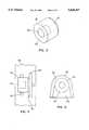
- FIG. 2is a detailed view of a damping cap.
- FIG. 3is a detailed bottom view of a cradle support and lateral support assembly in the upper housing.
- FIG. 4is a side view of the FIG. 3 assembly.
- FIG. 5shows a flexible electrical conductor arrangement
- FIGS. 6 and 7illustrate an alternative embodiment in accordance with the invention.
- FIG. 1One embodiment of a shock resistant portable electronic unit, in the form of a work slate unit utilizing the invention, is illustrated in FIG. 1.
- the work slateincludes a frame unit 12 adapted to support a large display portion 13 and associated electronic components 14, partially visible behind the display.
- frame unit 12may typically have the form of a generally rectangular structural frame having rail type longer side portions 15a and shorter end portions 15b.
- Frame unit 12is suitably configured for support of the majority of all display and electronic portions of the work slate unit in this example, and may include additional structural elements connected to or between side and end portions 15a and 15b behind the display portion 13.
- Frame unit 12also includes projections 16 configured for cooperation with shock absorbing means 18, as will be further described.
- the FIG. 1 unitalso includes a three-dimensional enclosure of shock resistant material, shown as comprising an upper section 26 having a large central opening and a lower section 28, which is enclosed except for various access openings.
- a three-dimensional enclosure of shock resistant materialshown as comprising an upper section 26 having a large central opening and a lower section 28, which is enclosed except for various access openings.
- An important aspect of the FIG. 1 unitis that the peripheral dimensions of the frame unit 12 are proportioned to fit within the assembled enclosure 24, 26 without physical contact between frame unit 12 and the enclosure.
- cap 18has the shape of a cylindrical section having a circular cross-sectional geometry with a circular opening 20 extending partially through the damping cap, so that opening 20 stops before reaching the far end of cap 18 which is not visible in FIG. 2.
- cap 18has an end wall thickness at 22 and a side wall thickness at 24 which can be specified by skilled persons on the basis of computation or empirical data in view of the weights and dimensions involved and the properties of the material of which the damping caps are formed in particular applications.
- Caps 18are desirably formed of material having shock absorbing or damping properties.
- elastomeric materials with damping propertieswhich have been found effective are "SANTOPRENE” which is produced by Monsanto Company of St. Louis, Mo. and "SORBOTHANE” which is produced by Sorbothane, Inc. of Kent, Ohio. Other materials having suitable properties may also be used.
- FIGS. 3 and 4show details of a cradle support and lateral support assembly such as incorporated into the structure of the upper enclosure section 26 of FIG. 1.
- FIG. 3is a bottom view looking up into section 26 with a damping cap 18 superimposed in working relationship
- FIG. 4is a side view.
- upper vertical positioning meansis shown as cradle support 32 having a contact area 33 whose side profile is an arc of a circle dimensioned to correspond to the circular cross-sectional geometry of damping cap 18, in this example.
- Lateral positioning meansis shown as lateral support 34 structurally supported by enclosure section 26 outward from cradle support 32.
- Lateral support 34is configured to provide a contact area 35 for contact with the closed end of cap 18.
- cradle supports 32are also positioned at locations spaced around the internal periphery of bottom section 28, however, bottom section 28 does not include any associated lateral supports 34.
- a damping cap 18is placed in position on each of the projections 16 existing at spaced positions on peripheral portions of frame unit 12.
- Frame unit 12is then positioned partially within upper section 26 so that each damping cap 18 rests on the contact area 33 of an upper cradle support 32, with the closed end of cap 18 positioned contiguously to the contact area 35 of a lateral support 34.
- the contact areas 33 of the lower cradle supports 32 of lower section 28are positioned contiguously to a lower portion of the circular cross-sectional geometry of the damping caps 18. Sections 26 and 28 are then fastened together.
- the shock absorbing meansin the form of the set of ten damping caps (three per end and two per side in this example), are positioned between peripheral portions of the frame unit 12 and the contact areas of the enclosure 26, 28, so that there is no physical contact between the frame unit and the enclosure.
- this arrangementis thus effective to both:
- drop shock forcesare defined as forces resulting from dropping the assembled unit onto a concrete floor or other surface from a distance.
- the objective hereis to provide improved protection for drops from reasonable heights, as well as from other shocks and impact type forces.
- the combination of the damping caps 18, the projections 16 and positioning means 32, 34provides support while additionally providing cushioning upon the occurrence of an impact upon the enclosure from above, below, left, right, at either end, or from any other direction, i.e., three-dimensional cushioning, as indicated by arrows A, B and C in FIG. 1, which is effective to dampen drop shock forces incident from any direction.
- the damping capsare positioned so that some of the caps will always be placed into compression regardless of the direction of impact upon the enclosure, prevention of dislocation of the frame unit and resistance to flexing or twisting forces are enhanced by not being dependent upon shearing or cross-tearing qualities of the damping caps.
- display 13is rigidly attached to frame unit 12 using fastening techniques well known in the art.
- Associated electronics 14may also be rigidly attached to frame unit 12, again using techniques well known in the art such as screws, bolts, or epoxy.
- a series of projections 16may be formed during a molding process or may be added separately as by insertion of pins into holes, again using known fastening techniques.
- each cap 18may be glued to projection 16 using suitable adhesives.
- Frame unit 12is then sandwiched between upper section 26 and lower section 28, in essence, enabling screen assembly 12 to "float" on caps 18.
- Upper section 26is connected to lower section 28 by screws or bolts through stanchions 30 to form a case for the device.
- stanchions 30to form a case for the device.
- other attachment methods for connecting upper section 26 to lower section 28may be substituted.
- each projection 16is typically cylindrical in shape and has a circular or other cross-sectional geometry (e.g., hexagonal or octagonal).
- each damping cap 18had an outside diameter of about one-half of an inch, an internal hole diameter of somewhat smaller than one-quarter of an inch, and a length of about three-eights of an inch.
- the damping capsare constructed of a thermoplastic elastomer or other material providing the desired shock absorption and dissipation properties; vibration transmission, performance at temperature extremes and other properties may also be taken into account in the choice of materials. Examples of types of appropriate material are given above.
- flexible electrical conductors illustrated as parallel conductor ribbon cable 40may be physically attached to both the lower enclosure section 28 and electronic components mounted on frame unit 12.
- frame unit 12may carry an outwardly extending electrical connector assembly 36 arranged to extend through an opening in the lower portion 42 of lower portion 28, for coupling to a connector 38 mounted on flexible cable 40.
- an opening 44may be provided so that even with connector assembly 36 coupled to an external cable, the frame unit 12 is still mechanically isolated from the enclosure with respect to impacts or mechanical shocks that are experienced by the enclosure 26, 28.
- FIG. 6includes a simplified representation of frame unit 12 upon which shock absorbing means in the form of a plurality of damping element sections 50 having a generally U-shaped cross-sectional geometry have been placed to encompass a peripheral portion of frame unit 12.
- FIG. 6 and other figuresare not necessarily to scale, certain dimensions having been enlarged for greater clarity.
- FIG. 7provides an end view of a damping element section 50, which may be formed of material having shock damping and dissipation properties as already discussed with reference to damping caps 18.
- damping element section 50is shown encompassing a peripheral portion of frame 12 of simplified cross-sectional profile.
- Portions 52 and 54 of modified forms of upper and lower enclosure sections, respectively,are also shown in FIG. 7.
- enclosure portions 52 and 54each include positioning means providing contact areas to support the frame unit via three-dimensional contact with the damping element sections 50 spaced around the periphery of frame unit 12 as shown in FIG. 6.
- Functioning of sections 50is basically as described with reference to damping caps 18.
- Damping element sections 50may also be provided in the modified form of corner configuration 56 and groups of sections 50 and sections 56 may be used separately, or intermixed as show, in different applications of the invention. Alternatively, a single damping element section may be formed in one piece to encompass the entire periphery of frame unit 12.
Landscapes
- Engineering & Computer Science (AREA)
- Theoretical Computer Science (AREA)
- Computer Hardware Design (AREA)
- Human Computer Interaction (AREA)
- Physics & Mathematics (AREA)
- General Engineering & Computer Science (AREA)
- General Physics & Mathematics (AREA)
- Microelectronics & Electronic Packaging (AREA)
- Casings For Electric Apparatus (AREA)
Abstract
Description
Claims (7)
Priority Applications (1)
| Application Number | Priority Date | Filing Date | Title |
|---|---|---|---|
| US08/260,102US5568357A (en) | 1994-06-15 | 1994-06-15 | Display support having cradled damping caps for floating core shock absorption |
Applications Claiming Priority (1)
| Application Number | Priority Date | Filing Date | Title |
|---|---|---|---|
| US08/260,102US5568357A (en) | 1994-06-15 | 1994-06-15 | Display support having cradled damping caps for floating core shock absorption |
Publications (1)
| Publication Number | Publication Date |
|---|---|
| US5568357Atrue US5568357A (en) | 1996-10-22 |
Family
ID=22987774
Family Applications (1)
| Application Number | Title | Priority Date | Filing Date |
|---|---|---|---|
| US08/260,102Expired - LifetimeUS5568357A (en) | 1994-06-15 | 1994-06-15 | Display support having cradled damping caps for floating core shock absorption |
Country Status (1)
| Country | Link |
|---|---|
| US (1) | US5568357A (en) |
Cited By (77)
| Publication number | Priority date | Publication date | Assignee | Title |
|---|---|---|---|---|
| US5668697A (en)* | 1995-04-20 | 1997-09-16 | Hewlett-Packard Company | Data storage module having cradles on housing and elastomeric member mounted on data storage mechanism |
| EP0817345A1 (en)* | 1996-07-03 | 1998-01-07 | Sumitomo Wiring Systems, Ltd. | Electrical connection box |
| US5742476A (en)* | 1995-04-26 | 1998-04-21 | Sharp Kabushiki Kaisha | Information processing apparatus with positioners corresponding to display input region |
| EP0911717A1 (en)* | 1997-10-24 | 1999-04-28 | Hewlett-Packard Company | Flexible portable computer |
| US6034867A (en)* | 1996-06-20 | 2000-03-07 | Samsung Electronics Co., Ltd. | Portable computer having a locking assembly |
| US6064565A (en)* | 1997-09-04 | 2000-05-16 | International Business Machines Corporation | LCD assembly and information processing apparatus |
| US6079332A (en)* | 1996-11-01 | 2000-06-27 | The Ensign-Bickford Company | Shock-resistant electronic circuit assembly |
| US6128183A (en)* | 1997-05-09 | 2000-10-03 | International Business Machines Corporation | Attachment structure for a display device and an equipment in which such structure is provided |
| EP0880049B1 (en)* | 1997-04-08 | 2001-01-17 | Lg Electronics Inc. | Computer comprising a LCD device |
| US6188568B1 (en)* | 1999-04-28 | 2001-02-13 | Compal Electronics, Inc. | Display panel for a portable computer |
| US6186400B1 (en)* | 1998-03-20 | 2001-02-13 | Symbol Technologies, Inc. | Bar code reader with an integrated scanning component module mountable on printed circuit board |
| US6233140B1 (en)* | 1999-01-22 | 2001-05-15 | Dell U.S.A., L.P. | Electrically conductive vibration dampener |
| US6304440B1 (en)* | 1999-11-04 | 2001-10-16 | Liken Lin | Shock-proof device of external hard disk driver box |
| US20010035921A1 (en)* | 2000-04-26 | 2001-11-01 | Masahiko Yamanami | Method for mounting display panel used in information processing apparatus and display panel housing therefor |
| US6311621B1 (en) | 1996-11-01 | 2001-11-06 | The Ensign-Bickford Company | Shock-resistant electronic circuit assembly |
| US6362953B1 (en)* | 1999-12-27 | 2002-03-26 | Carrier Corporation | Control device assembly |
| US20020043608A1 (en)* | 2000-06-01 | 2002-04-18 | Fujitsu Limited | Shock absorbing member capable of absorbing larger impact applied to electronic apparatus |
| US20020080299A1 (en)* | 1997-04-08 | 2002-06-27 | Yun Hee Young | Computer having liquid crystal display |
| US6430039B2 (en)* | 1996-10-21 | 2002-08-06 | Kabushiki Kaisha Toshiba | Portable information apparatus having a display unit comprising a housing and a display contained in the housing |
| US6522372B2 (en)* | 2001-05-21 | 2003-02-18 | Samsung Electronics Co., Ltd. | Liquid crystal display monitor having simplified assembly process |
| US6532152B1 (en)* | 1998-11-16 | 2003-03-11 | Intermec Ip Corp. | Ruggedized hand held computer |
| US6545733B2 (en)* | 1995-04-18 | 2003-04-08 | Canon Kabushiki Kaisha | Display apparatus |
| US20030128503A1 (en)* | 2001-12-07 | 2003-07-10 | Hitoshi Takahashi | Display apparatus |
| US20030169563A1 (en)* | 2002-03-06 | 2003-09-11 | Adams Michael D. | Ergonomic hand held display |
| US20040027796A1 (en)* | 2002-08-07 | 2004-02-12 | Jr-Teng Shih | Bumper |
| EP1402309A1 (en)* | 2001-06-28 | 2004-03-31 | Siemens Aktiengesellschaft | Retaining device for the floating mounting of a flat screen, and electronic display device comprising a flat screen and a retaining device |
| US6744903B1 (en)* | 1999-04-15 | 2004-06-01 | Lg Electronics Inc. | Multiple damping device of speaker system for video display equipment |
| US20040189886A1 (en)* | 2003-03-28 | 2004-09-30 | Chia-Lin Chang | Structure for absorbing the shock |
| US6838810B1 (en) | 1997-03-21 | 2005-01-04 | Chunghwa Picture Tubes, Ltd. | Flat-panel display mounting system for portable computer |
| EP1499170A1 (en)* | 2003-07-15 | 2005-01-19 | Siemens Aktiengesellschaft | Component carrier |
| US20050168930A1 (en)* | 1998-10-23 | 2005-08-04 | Kim Jong H. | Portable computer and method for mounting a flat panel display device thereon |
| US20060120035A1 (en)* | 2001-04-24 | 2006-06-08 | Nick Merz | Computer component protection |
| US20060145043A1 (en)* | 2004-12-30 | 2006-07-06 | Hannspree, Inc. | Display device with a foldable suspension arm |
| USD525975S1 (en)* | 2003-07-11 | 2006-08-01 | Hewlett-Packard Development Company, L.P. | Optical scanner |
| US20060171106A1 (en)* | 1998-11-11 | 2006-08-03 | Cho Young W | Portable computer and method for mounting a flat panel display device module |
| US20060181843A1 (en)* | 2005-02-14 | 2006-08-17 | Kabushiki Kaisha Toshiba | Portable microcomputer and display unit |
| WO2006100178A1 (en)* | 2005-03-23 | 2006-09-28 | Thomson Licensing | Flat screen display device comprising points for fixing said screen to a cabinet |
| US20060227499A1 (en)* | 2002-12-24 | 2006-10-12 | Jeong Ki R | Liquid crystal display device |
| USD533552S1 (en)* | 2005-05-18 | 2006-12-12 | Nec Infrontia Corporation | Personal digital assistant |
| US7172114B2 (en) | 2004-12-30 | 2007-02-06 | Hand Held Products, Inc. | Tamperproof point of sale transaction terminal |
| KR100700610B1 (en)* | 2001-09-13 | 2007-03-28 | 엘지전자 주식회사 | Portable electronic devices |
| US20070279859A1 (en)* | 1999-02-04 | 2007-12-06 | Canova Francis J Jr | Handheld computer |
| US20070285878A1 (en)* | 2006-06-08 | 2007-12-13 | Kabushiki Kaisha Toshiba | Electronic appartus |
| US20080094787A1 (en)* | 2004-03-15 | 2008-04-24 | Olympus Technologies Pte Ltd. | Portable Electronic Device |
| US7382911B1 (en) | 2001-02-16 | 2008-06-03 | Hand Held Products, Inc. | Identification card reader |
| US7451917B2 (en) | 2002-01-11 | 2008-11-18 | Hand Held Products, Inc. | Transaction terminal comprising imaging module |
| US20080297013A1 (en)* | 2007-05-30 | 2008-12-04 | Funai Electric Co., Ltd. | Assembly structure of a cabinet and thin display device |
| US7472825B2 (en) | 2002-01-11 | 2009-01-06 | Hand Held Products, Inc. | Transaction terminal |
| US7479946B2 (en) | 2002-01-11 | 2009-01-20 | Hand Held Products, Inc. | Ergonomically designed multifunctional transaction terminal |
| US7492421B1 (en) | 1997-07-03 | 2009-02-17 | Lg Display Co., Ltd. | Case for liquid crystal display |
| US20100128459A1 (en)* | 2007-04-23 | 2010-05-27 | Continental Automotive Gmbh | Standardized support element with integrated interface |
| US7748620B2 (en) | 2002-01-11 | 2010-07-06 | Hand Held Products, Inc. | Transaction terminal including imaging module |
| US20100285850A1 (en)* | 2009-05-07 | 2010-11-11 | Todd Robert Paleczny | Gasket for a mobile device having a touch sensitive display |
| US20110081828A1 (en)* | 2009-10-06 | 2011-04-07 | Apple Inc. | Edge break details and processing |
| US20110081839A1 (en)* | 2009-10-06 | 2011-04-07 | Apple Inc. | Method and apparatus for polishing a curved edge |
| US20110090632A1 (en)* | 2009-10-16 | 2011-04-21 | Apple Inc. | Computer housing |
| US20110126440A1 (en)* | 2009-12-01 | 2011-06-02 | Samsung Electronics Co., Ltd. | Display apparatus |
| CN102098890A (en)* | 2011-01-28 | 2011-06-15 | 鸿富锦精密工业(深圳)有限公司 | Electronic equipment |
| EP1591870A3 (en)* | 2004-04-27 | 2011-06-22 | Continental Automotive GmbH | Supporting element and arrangement for supporting a display against a casing |
| CN101661306B (en)* | 2008-08-29 | 2011-08-24 | 佛山市顺德区汉达精密电子科技有限公司 | Buffer structure of display |
| US20110227849A1 (en)* | 2010-03-18 | 2011-09-22 | Immersion Corporation | Grommet Suspension Component and System |
| US8373985B2 (en)* | 2010-05-06 | 2013-02-12 | Research In Motion Limited | Molded assembly |
| US20130088813A1 (en)* | 2011-10-10 | 2013-04-11 | AFC Trident, Inc. | Modular protective cover with accessory slot for portable electronic device |
| US8508927B2 (en) | 2010-09-24 | 2013-08-13 | Research In Motion Limited | Gasket and display assembly for an electronic mobile device |
| US20140076753A1 (en)* | 2012-09-17 | 2014-03-20 | Jamie Limber | Case for wireless devices |
| US8723804B2 (en) | 2005-02-11 | 2014-05-13 | Hand Held Products, Inc. | Transaction terminal and adaptor therefor |
| US20140211386A1 (en)* | 2011-09-15 | 2014-07-31 | Hewlett-Packard Development Company, L.P. | Computer devices and methods of preventing damage to a display |
| US9195083B2 (en)* | 2011-10-31 | 2015-11-24 | Microsoft Technology Licensing, Llc | Impact resistant construction of an interactive device |
| US9213409B2 (en) | 2013-11-25 | 2015-12-15 | Immersion Corporation | Dual stiffness suspension system |
| US9402122B2 (en) | 2001-11-19 | 2016-07-26 | Otter Products, Llc | Protective enclosure for electronic device |
| US9466783B2 (en) | 2012-07-26 | 2016-10-11 | Immersion Corporation | Suspension element having integrated piezo material for providing haptic effects to a touch screen |
| US20160297376A1 (en)* | 2014-05-28 | 2016-10-13 | Boe Technology Group Co., Ltd. | Vibration dampening assembly for fixing a display device and display apparatus |
| US9632582B2 (en) | 2014-12-22 | 2017-04-25 | Immersion Corporation | Magnetic suspension system for touch screens and touch surfaces |
| CN107949193A (en)* | 2017-11-08 | 2018-04-20 | 苏州蓝博控制技术有限公司 | Installation shell with shock-damping structure and liquid crystal display instrument is bonded entirely |
| US10275032B2 (en) | 2016-12-22 | 2019-04-30 | Immersion Corporation | Pressure-sensitive suspension system for a haptic device |
| US10343061B2 (en) | 2014-12-22 | 2019-07-09 | Immersion Corporation | Haptic actuators having magnetic elements and at least one electromagnet |
| US10765027B2 (en)* | 2014-10-21 | 2020-09-01 | Thales | Assembly for attaching and connecting a computer data storage device to an on-board computer and associated method for use |
Citations (5)
| Publication number | Priority date | Publication date | Assignee | Title |
|---|---|---|---|---|
| US5192143A (en)* | 1992-05-15 | 1993-03-09 | Sun Microsystems, Inc. | Quick connect modular unit retainer assembly with damping |
| US5363227A (en)* | 1989-05-31 | 1994-11-08 | Fujitsu Personal Systems, Inc. | Liquid crystal display mounting structure |
| US5394306A (en)* | 1993-09-07 | 1995-02-28 | Norand Corporation | Shock absorbent packaging apparatus |
| US5419626A (en)* | 1993-09-01 | 1995-05-30 | Ncr Corporation | Computer housing seal |
| US5479285A (en)* | 1993-09-01 | 1995-12-26 | Ncr Corporation | Liquid crystal device with an isotropic shock mounting and gasket |
- 1994
- 1994-06-15USUS08/260,102patent/US5568357A/ennot_activeExpired - Lifetime
Patent Citations (5)
| Publication number | Priority date | Publication date | Assignee | Title |
|---|---|---|---|---|
| US5363227A (en)* | 1989-05-31 | 1994-11-08 | Fujitsu Personal Systems, Inc. | Liquid crystal display mounting structure |
| US5192143A (en)* | 1992-05-15 | 1993-03-09 | Sun Microsystems, Inc. | Quick connect modular unit retainer assembly with damping |
| US5419626A (en)* | 1993-09-01 | 1995-05-30 | Ncr Corporation | Computer housing seal |
| US5479285A (en)* | 1993-09-01 | 1995-12-26 | Ncr Corporation | Liquid crystal device with an isotropic shock mounting and gasket |
| US5394306A (en)* | 1993-09-07 | 1995-02-28 | Norand Corporation | Shock absorbent packaging apparatus |
Cited By (146)
| Publication number | Priority date | Publication date | Assignee | Title |
|---|---|---|---|---|
| US6545733B2 (en)* | 1995-04-18 | 2003-04-08 | Canon Kabushiki Kaisha | Display apparatus |
| US5668697A (en)* | 1995-04-20 | 1997-09-16 | Hewlett-Packard Company | Data storage module having cradles on housing and elastomeric member mounted on data storage mechanism |
| US5742476A (en)* | 1995-04-26 | 1998-04-21 | Sharp Kabushiki Kaisha | Information processing apparatus with positioners corresponding to display input region |
| US6034867A (en)* | 1996-06-20 | 2000-03-07 | Samsung Electronics Co., Ltd. | Portable computer having a locking assembly |
| EP0817345A1 (en)* | 1996-07-03 | 1998-01-07 | Sumitomo Wiring Systems, Ltd. | Electrical connection box |
| US6430039B2 (en)* | 1996-10-21 | 2002-08-06 | Kabushiki Kaisha Toshiba | Portable information apparatus having a display unit comprising a housing and a display contained in the housing |
| US6079332A (en)* | 1996-11-01 | 2000-06-27 | The Ensign-Bickford Company | Shock-resistant electronic circuit assembly |
| US6311621B1 (en) | 1996-11-01 | 2001-11-06 | The Ensign-Bickford Company | Shock-resistant electronic circuit assembly |
| US7310222B2 (en) | 1997-03-21 | 2007-12-18 | Chunghwa Picture Tubes, Ltd. | Flat-panel display mounting system for portable computer |
| US20060198090A1 (en)* | 1997-03-21 | 2006-09-07 | Michele Bovio | Flat-panel display mounting system for portable computer |
| US20050082961A1 (en)* | 1997-03-21 | 2005-04-21 | Michele Bovio | Flat-panel display mounting system for portable computer |
| US6838810B1 (en) | 1997-03-21 | 2005-01-04 | Chunghwa Picture Tubes, Ltd. | Flat-panel display mounting system for portable computer |
| US20050088075A1 (en)* | 1997-03-21 | 2005-04-28 | Michele Bovio | Flat-panel display mounting system for portable computer |
| US20060209504A1 (en)* | 1997-03-21 | 2006-09-21 | Michele Bovio | Flat-panel display mounting system for portable computer |
| US20050088810A1 (en)* | 1997-03-21 | 2005-04-28 | Michele Bovio | Flat-panel display mounting system for portable computer |
| US20060209503A1 (en)* | 1997-03-21 | 2006-09-21 | Michele Bovio | Flat-panel display mounting system for portable computer |
| US20060198091A1 (en)* | 1997-03-21 | 2006-09-07 | Michele Bovio | Flat-panel display mounting system for portable computer |
| US20050078439A1 (en)* | 1997-03-21 | 2005-04-14 | Michele Bovio | Flat-panel display mounting system for portable computer |
| US7944517B2 (en) | 1997-04-08 | 2011-05-17 | Lg Display, Co., Ltd. | Computer having liquid crystal display |
| US7944522B2 (en) | 1997-04-08 | 2011-05-17 | Lg Display Co., Ltd. | Computer having liquid crystal display |
| US20020080299A1 (en)* | 1997-04-08 | 2002-06-27 | Yun Hee Young | Computer having liquid crystal display |
| EP0880049B1 (en)* | 1997-04-08 | 2001-01-17 | Lg Electronics Inc. | Computer comprising a LCD device |
| US6128183A (en)* | 1997-05-09 | 2000-10-03 | International Business Machines Corporation | Attachment structure for a display device and an equipment in which such structure is provided |
| US7492421B1 (en) | 1997-07-03 | 2009-02-17 | Lg Display Co., Ltd. | Case for liquid crystal display |
| US6064565A (en)* | 1997-09-04 | 2000-05-16 | International Business Machines Corporation | LCD assembly and information processing apparatus |
| EP0911717A1 (en)* | 1997-10-24 | 1999-04-28 | Hewlett-Packard Company | Flexible portable computer |
| US6186400B1 (en)* | 1998-03-20 | 2001-02-13 | Symbol Technologies, Inc. | Bar code reader with an integrated scanning component module mountable on printed circuit board |
| US6669097B2 (en)* | 1998-03-20 | 2003-12-30 | Symbol Technologies, Inc. | Bar code reader with an integrated scanning component module mountable on printed circuit board |
| US20050195560A1 (en)* | 1998-10-23 | 2005-09-08 | Kim Jong H. | Portable computer and method for mounting a flat panel display device thereon |
| US7907399B2 (en) | 1998-10-23 | 2011-03-15 | Lg Display Co., Ltd. | Portable computer and method for mounting a flat panel display device thereon |
| US7885059B2 (en) | 1998-10-23 | 2011-02-08 | Lg Display Co., Ltd. | Portable computer and method for mounting a flat panel display device thereon |
| US7864138B2 (en) | 1998-10-23 | 2011-01-04 | Lg Display Co., Ltd. | Portable computer and method for mounting a flat panel display device thereon |
| US20050168930A1 (en)* | 1998-10-23 | 2005-08-04 | Kim Jong H. | Portable computer and method for mounting a flat panel display device thereon |
| US7828616B2 (en) | 1998-10-23 | 2010-11-09 | Lg Display Co., Ltd. | Method of forming a portable computer having a flat panel display device |
| US20060171106A1 (en)* | 1998-11-11 | 2006-08-03 | Cho Young W | Portable computer and method for mounting a flat panel display device module |
| US7663871B2 (en) | 1998-11-11 | 2010-02-16 | Lg Display Co., Ltd. | Portable computer and method for mounting a flat panel display device module |
| US6532152B1 (en)* | 1998-11-16 | 2003-03-11 | Intermec Ip Corp. | Ruggedized hand held computer |
| US6233140B1 (en)* | 1999-01-22 | 2001-05-15 | Dell U.S.A., L.P. | Electrically conductive vibration dampener |
| US8804332B2 (en)* | 1999-02-04 | 2014-08-12 | Hewlett-Packard Development Company, L.P. | Handheld computer |
| US9367083B2 (en) | 1999-02-04 | 2016-06-14 | Hewlett-Packard Development Company, L.P. | Computing device housing |
| US20070279859A1 (en)* | 1999-02-04 | 2007-12-06 | Canova Francis J Jr | Handheld computer |
| US6744903B1 (en)* | 1999-04-15 | 2004-06-01 | Lg Electronics Inc. | Multiple damping device of speaker system for video display equipment |
| US6188568B1 (en)* | 1999-04-28 | 2001-02-13 | Compal Electronics, Inc. | Display panel for a portable computer |
| US6304440B1 (en)* | 1999-11-04 | 2001-10-16 | Liken Lin | Shock-proof device of external hard disk driver box |
| US6362953B1 (en)* | 1999-12-27 | 2002-03-26 | Carrier Corporation | Control device assembly |
| US20010035921A1 (en)* | 2000-04-26 | 2001-11-01 | Masahiko Yamanami | Method for mounting display panel used in information processing apparatus and display panel housing therefor |
| US20020043608A1 (en)* | 2000-06-01 | 2002-04-18 | Fujitsu Limited | Shock absorbing member capable of absorbing larger impact applied to electronic apparatus |
| US6809916B2 (en)* | 2000-06-01 | 2004-10-26 | Fujitsu Limited | Shock absorbing member capable of absorbing larger impact applied to electronic apparatus |
| US7382911B1 (en) | 2001-02-16 | 2008-06-03 | Hand Held Products, Inc. | Identification card reader |
| US20090040698A1 (en)* | 2001-04-24 | 2009-02-12 | Apple Inc. | Computer component protection |
| US7457111B2 (en) | 2001-04-24 | 2008-11-25 | Apple Inc. | Computer component protection |
| US8605426B2 (en) | 2001-04-24 | 2013-12-10 | Apple Inc. | Heat dissipation in computing device |
| US20070165373A1 (en)* | 2001-04-24 | 2007-07-19 | Apple Computer, Inc. | Computer component protection |
| US9116674B2 (en) | 2001-04-24 | 2015-08-25 | Apple Inc. | Heat dissipation in computing device |
| US8050028B2 (en) | 2001-04-24 | 2011-11-01 | Apple Inc. | Heat dissipation in computing device |
| US7835147B2 (en) | 2001-04-24 | 2010-11-16 | Apple Inc. | Computer component protection |
| US20060120035A1 (en)* | 2001-04-24 | 2006-06-08 | Nick Merz | Computer component protection |
| US7301761B2 (en)* | 2001-04-24 | 2007-11-27 | Apple Inc. | Computer component protection |
| US6522372B2 (en)* | 2001-05-21 | 2003-02-18 | Samsung Electronics Co., Ltd. | Liquid crystal display monitor having simplified assembly process |
| EP1402309A1 (en)* | 2001-06-28 | 2004-03-31 | Siemens Aktiengesellschaft | Retaining device for the floating mounting of a flat screen, and electronic display device comprising a flat screen and a retaining device |
| US7267313B2 (en)* | 2001-06-28 | 2007-09-11 | Siemens Aktiengesellschaft | Retaining device for the floating mounting of a flat screen and electronic display device comprising a flat screen and a retaining device |
| US20040182979A1 (en)* | 2001-06-28 | 2004-09-23 | Siemens Ag | Retaining device for the floating mounting of a flat screen and electronic display device comprising a flat screen and a retaining device |
| KR100700610B1 (en)* | 2001-09-13 | 2007-03-28 | 엘지전자 주식회사 | Portable electronic devices |
| US9906259B2 (en) | 2001-11-19 | 2018-02-27 | Otter Products, Llc | Protective cover for electronic device |
| US10044396B2 (en) | 2001-11-19 | 2018-08-07 | Otter Products, Llc | Protective cover for electronic device |
| US9402122B2 (en) | 2001-11-19 | 2016-07-26 | Otter Products, Llc | Protective enclosure for electronic device |
| US10340970B2 (en) | 2001-11-19 | 2019-07-02 | Otter Products, Llc | Protective cover for electronic device |
| US9735827B2 (en) | 2001-11-19 | 2017-08-15 | Otter Products, Llc | Protective enclosure for electronic device |
| US9560435B2 (en) | 2001-11-19 | 2017-01-31 | Otter Products, Llc | Protective enclosure for electronic device |
| US6807051B2 (en)* | 2001-12-07 | 2004-10-19 | Sony Corporation | Display apparatus |
| US20030128503A1 (en)* | 2001-12-07 | 2003-07-10 | Hitoshi Takahashi | Display apparatus |
| US7748620B2 (en) | 2002-01-11 | 2010-07-06 | Hand Held Products, Inc. | Transaction terminal including imaging module |
| US8561895B2 (en) | 2002-01-11 | 2013-10-22 | Hand Held Products, Inc. | Terminal including imaging assembly |
| US7451917B2 (en) | 2002-01-11 | 2008-11-18 | Hand Held Products, Inc. | Transaction terminal comprising imaging module |
| US9734493B2 (en) | 2002-01-11 | 2017-08-15 | Hand Held Products, Inc. | Terminal including imaging assembly |
| US8544737B2 (en) | 2002-01-11 | 2013-10-01 | Hand Held Products, Inc. | Terminal including imaging assembly |
| US8967468B2 (en) | 2002-01-11 | 2015-03-03 | Hand Held Products, Inc. | Terminal including imaging assembly |
| US7472825B2 (en) | 2002-01-11 | 2009-01-06 | Hand Held Products, Inc. | Transaction terminal |
| US7479946B2 (en) | 2002-01-11 | 2009-01-20 | Hand Held Products, Inc. | Ergonomically designed multifunctional transaction terminal |
| US6937464B2 (en) | 2002-03-06 | 2005-08-30 | Xybernaut Corp. | Ergonomic hand held display |
| US20030169563A1 (en)* | 2002-03-06 | 2003-09-11 | Adams Michael D. | Ergonomic hand held display |
| US20040240163A1 (en)* | 2002-03-06 | 2004-12-02 | Adams Michael D. | Ergonomic hand held display |
| US6757156B2 (en)* | 2002-03-06 | 2004-06-29 | Xybernaut Corporation | Ergonomic hand held display |
| US20040027796A1 (en)* | 2002-08-07 | 2004-02-12 | Jr-Teng Shih | Bumper |
| US6781825B2 (en)* | 2002-08-07 | 2004-08-24 | Quanta Computer, Inc. | Bumper |
| US7274560B2 (en)* | 2002-12-24 | 2007-09-25 | Lg.Philips Lcd Co., Ltd. | Liquid crystal display device |
| CN100462779C (en)* | 2002-12-24 | 2009-02-18 | 乐金显示有限公司 | display device |
| US20060227499A1 (en)* | 2002-12-24 | 2006-10-12 | Jeong Ki R | Liquid crystal display device |
| US20040189886A1 (en)* | 2003-03-28 | 2004-09-30 | Chia-Lin Chang | Structure for absorbing the shock |
| USD525975S1 (en)* | 2003-07-11 | 2006-08-01 | Hewlett-Packard Development Company, L.P. | Optical scanner |
| US20070076351A1 (en)* | 2003-07-15 | 2007-04-05 | Siemens Aktiengesellschaft | Component carrier |
| CN100446644C (en)* | 2003-07-15 | 2008-12-24 | 西门子公司 | Parts bracket |
| EP1499170A1 (en)* | 2003-07-15 | 2005-01-19 | Siemens Aktiengesellschaft | Component carrier |
| WO2005015969A1 (en)* | 2003-07-15 | 2005-02-17 | Siemens Aktiengesellschaft | Component carrier |
| US20080094787A1 (en)* | 2004-03-15 | 2008-04-24 | Olympus Technologies Pte Ltd. | Portable Electronic Device |
| EP1591870A3 (en)* | 2004-04-27 | 2011-06-22 | Continental Automotive GmbH | Supporting element and arrangement for supporting a display against a casing |
| US7210662B2 (en)* | 2004-12-30 | 2007-05-01 | Hannspree, Inc. | Display device with a foldable suspension arm |
| US20060145043A1 (en)* | 2004-12-30 | 2006-07-06 | Hannspree, Inc. | Display device with a foldable suspension arm |
| US7172114B2 (en) | 2004-12-30 | 2007-02-06 | Hand Held Products, Inc. | Tamperproof point of sale transaction terminal |
| US8723804B2 (en) | 2005-02-11 | 2014-05-13 | Hand Held Products, Inc. | Transaction terminal and adaptor therefor |
| US7420798B2 (en)* | 2005-02-14 | 2008-09-02 | Kabushiki Kaisha Toshiba | Portable microcomputer and display unit |
| US20060181843A1 (en)* | 2005-02-14 | 2006-08-17 | Kabushiki Kaisha Toshiba | Portable microcomputer and display unit |
| WO2006100178A1 (en)* | 2005-03-23 | 2006-09-28 | Thomson Licensing | Flat screen display device comprising points for fixing said screen to a cabinet |
| JP2008538144A (en)* | 2005-03-23 | 2008-10-09 | トムソン ライセンシング | Flat screen display with points that secure the screen to the cabinet |
| FR2883657A1 (en)* | 2005-03-23 | 2006-09-29 | Thomson Licensing Sa | FLAT SCREEN DISPLAY DEVICE WITH SCREEN FASTENING POINTS TO A BOX |
| USD533552S1 (en)* | 2005-05-18 | 2006-12-12 | Nec Infrontia Corporation | Personal digital assistant |
| US7606023B2 (en) | 2006-06-08 | 2009-10-20 | Kabushiki Kaisha Toshiba | Electronic apparatus |
| US20070285878A1 (en)* | 2006-06-08 | 2007-12-13 | Kabushiki Kaisha Toshiba | Electronic appartus |
| US8111527B2 (en)* | 2007-04-23 | 2012-02-07 | Continental Automotive Gmbh | Standardized support element with integrated interface |
| US20100128459A1 (en)* | 2007-04-23 | 2010-05-27 | Continental Automotive Gmbh | Standardized support element with integrated interface |
| US8366213B2 (en)* | 2007-05-30 | 2013-02-05 | Funai Electric Co., Ltd. | Assembly structure of a cabinet and thin display device |
| US20080297013A1 (en)* | 2007-05-30 | 2008-12-04 | Funai Electric Co., Ltd. | Assembly structure of a cabinet and thin display device |
| CN101661306B (en)* | 2008-08-29 | 2011-08-24 | 佛山市顺德区汉达精密电子科技有限公司 | Buffer structure of display |
| US8260377B2 (en) | 2009-05-07 | 2012-09-04 | Research In Motion Limited | Gasket for a mobile device having a touch sensitive display |
| US20100285850A1 (en)* | 2009-05-07 | 2010-11-11 | Todd Robert Paleczny | Gasket for a mobile device having a touch sensitive display |
| US20110081828A1 (en)* | 2009-10-06 | 2011-04-07 | Apple Inc. | Edge break details and processing |
| US20110081839A1 (en)* | 2009-10-06 | 2011-04-07 | Apple Inc. | Method and apparatus for polishing a curved edge |
| US8892238B2 (en) | 2009-10-06 | 2014-11-18 | Edward T. Sweet | Edge break details and processing |
| US8780539B2 (en)* | 2009-10-16 | 2014-07-15 | Apple Inc. | Computer housing |
| US20120092821A1 (en)* | 2009-10-16 | 2012-04-19 | Apple Inc. | Computer housing |
| US8111505B2 (en)* | 2009-10-16 | 2012-02-07 | Apple Inc. | Computer housing |
| US20110090632A1 (en)* | 2009-10-16 | 2011-04-21 | Apple Inc. | Computer housing |
| US8434251B2 (en)* | 2009-12-01 | 2013-05-07 | Samsung Electronics Co., Ltd. | Display apparatus |
| US20110126440A1 (en)* | 2009-12-01 | 2011-06-02 | Samsung Electronics Co., Ltd. | Display apparatus |
| US8629954B2 (en)* | 2010-03-18 | 2014-01-14 | Immersion Corporation | Grommet suspension component and system |
| US20110227849A1 (en)* | 2010-03-18 | 2011-09-22 | Immersion Corporation | Grommet Suspension Component and System |
| US8373985B2 (en)* | 2010-05-06 | 2013-02-12 | Research In Motion Limited | Molded assembly |
| US8508927B2 (en) | 2010-09-24 | 2013-08-13 | Research In Motion Limited | Gasket and display assembly for an electronic mobile device |
| CN102098890A (en)* | 2011-01-28 | 2011-06-15 | 鸿富锦精密工业(深圳)有限公司 | Electronic equipment |
| US20140211386A1 (en)* | 2011-09-15 | 2014-07-31 | Hewlett-Packard Development Company, L.P. | Computer devices and methods of preventing damage to a display |
| US9405322B2 (en)* | 2011-09-15 | 2016-08-02 | Hewlett-Packard Development Company, L.P. | Computer devices and methods of preventing damage to a display |
| US20130088813A1 (en)* | 2011-10-10 | 2013-04-11 | AFC Trident, Inc. | Modular protective cover with accessory slot for portable electronic device |
| US9116665B2 (en)* | 2011-10-10 | 2015-08-25 | AFC Trident, Inc. | Modular protective cover with accessory slot for portable electronic device |
| US9195083B2 (en)* | 2011-10-31 | 2015-11-24 | Microsoft Technology Licensing, Llc | Impact resistant construction of an interactive device |
| US9466783B2 (en) | 2012-07-26 | 2016-10-11 | Immersion Corporation | Suspension element having integrated piezo material for providing haptic effects to a touch screen |
| US20140076753A1 (en)* | 2012-09-17 | 2014-03-20 | Jamie Limber | Case for wireless devices |
| US9213409B2 (en) | 2013-11-25 | 2015-12-15 | Immersion Corporation | Dual stiffness suspension system |
| US9501172B2 (en) | 2013-11-25 | 2016-11-22 | Immersion Corporation | Dual stiffness suspension system |
| US20160297376A1 (en)* | 2014-05-28 | 2016-10-13 | Boe Technology Group Co., Ltd. | Vibration dampening assembly for fixing a display device and display apparatus |
| US10765027B2 (en)* | 2014-10-21 | 2020-09-01 | Thales | Assembly for attaching and connecting a computer data storage device to an on-board computer and associated method for use |
| US9632582B2 (en) | 2014-12-22 | 2017-04-25 | Immersion Corporation | Magnetic suspension system for touch screens and touch surfaces |
| US10343061B2 (en) | 2014-12-22 | 2019-07-09 | Immersion Corporation | Haptic actuators having magnetic elements and at least one electromagnet |
| US10275032B2 (en) | 2016-12-22 | 2019-04-30 | Immersion Corporation | Pressure-sensitive suspension system for a haptic device |
| US10698491B2 (en) | 2016-12-22 | 2020-06-30 | Immersion Corporation | Pressure-sensitive suspension system for a haptic device |
| CN107949193A (en)* | 2017-11-08 | 2018-04-20 | 苏州蓝博控制技术有限公司 | Installation shell with shock-damping structure and liquid crystal display instrument is bonded entirely |
| CN107949193B (en)* | 2017-11-08 | 2023-12-01 | 苏州蓝博控制技术有限公司 | Mounting shell with shock-absorbing structure and full-lamination liquid crystal display instrument |
Similar Documents
| Publication | Publication Date | Title |
|---|---|---|
| US5568357A (en) | Display support having cradled damping caps for floating core shock absorption | |
| CN100476688C (en) | Display unit | |
| US7471509B1 (en) | Shock protection for disk drive embedded in an enclosure | |
| US8797749B2 (en) | Electronic apparatus including bumper portion protecting housing | |
| US7593221B2 (en) | Anti-vibration and anti-electromagnetic-interfering frame for hard disk | |
| US7743995B2 (en) | Terminal design with shock isolation assembly | |
| KR101037877B1 (en) | Digital storage arrangement | |
| EP3729991B1 (en) | Case structure | |
| US6021041A (en) | Tuned shock absorbing system for portable computer hard disc drives | |
| EP0642089B1 (en) | Computer display assembly | |
| US8289693B2 (en) | Disk drive assembly | |
| US20120104222A1 (en) | Mounting apparatus for data storage device | |
| US7092250B2 (en) | Vibration-proof removable module | |
| RU89750U1 (en) | SHOCK RESISTANT AND VIBRATION RESISTANT COMPARTMENT FOR A HARD DRIVE | |
| JP2010067730A (en) | Shock absorbing structure | |
| US20190009965A1 (en) | Ruggedized enclosure for data storage device | |
| US8286932B2 (en) | Mounting apparatus for storage device | |
| CN204694263U (en) | A kind of inertial measuring unit | |
| JPH10322039A (en) | Impact resistant structure of electronic equipment | |
| US20030035281A1 (en) | Shock absorber module | |
| JPH06236669A (en) | Shock absorber member for storage device | |
| CN203013259U (en) | Multi-thickness hard disk drive snubber | |
| JP4573740B2 (en) | Attachment for protection of electronic equipment | |
| US6222121B1 (en) | Data storage apparatus with a buffer frame | |
| CN100524157C (en) | Shock-proof module device and data processing system |
Legal Events
| Date | Code | Title | Description |
|---|---|---|---|
| AS | Assignment | Owner name:METANETICS CORPORATION, FLORIDA Free format text:ASSIGNMENT OF ASSIGNORS INTEREST;ASSIGNORS:KOCHIS, GARY;DELAPLANE, NEIL C.;REBH, WILLIAM R.;AND OTHERS;REEL/FRAME:007132/0976 Effective date:19940822 | |
| AS | Assignment | Owner name:BANK OF NEW YORK COMMERCIAL CORPORATION, THE, AS A Free format text:SECURITY INTEREST;ASSIGNOR:TELETRANSACTION, INC.;REEL/FRAME:007532/0730 Effective date:19950616 | |
| AS | Assignment | Owner name:TELETRANSACTION, INC., OHIO Free format text:RELEASE OF PATENT ASSIGNMENT OF SECURITY;ASSIGNOR:BANK OF NEW YORK COMMERCDIAL CORPRATION, THE, AS AGENT, BY: DANIEL J. MURRAY, VP;REEL/FRAME:007926/0671 Effective date:19960308 | |
| AS | Assignment | Owner name:TELETRANSACTION, INC., OHIO Free format text:A CORRECTIVE ASSIGNMENT TO CORRECT ASSIGNEE ON REEL 7132, FRAME 0976;ASSIGNORS:KOCHIS, GARY;DELAPLANE, NEIL C.;REBH, WILLIAM R.;AND OTHERS;REEL/FRAME:008076/0421;SIGNING DATES FROM 19940819 TO 19940822 | |
| STCF | Information on status: patent grant | Free format text:PATENTED CASE | |
| AS | Assignment | Owner name:TELXON CORPORATION, OHIO Free format text:ASSIGNMENT OF ASSIGNORS INTEREST;ASSIGNOR:TELETRANSACTIONS, INC.;REEL/FRAME:009781/0759 Effective date:19990201 | |
| AS | Assignment | Owner name:BANK OF NEW YORK, THE, NEW YORK Free format text:SECURITY INTEREST;ASSIGNOR:TELETRANSACTION, INC.;REEL/FRAME:009860/0028 Effective date:19990326 | |
| AS | Assignment | Owner name:BANK OF NEW YORK, THE, NEW YORK Free format text:SECURITY INTEREST;ASSIGNOR:TELXON CORPORATION;REEL/FRAME:009817/0901 Effective date:19990326 | |
| AS | Assignment | Owner name:BANK OF NEW YORK, THE, NEW YORK Free format text:SECURITY AGREEMENT;ASSIGNOR:TELXON CORPORATION;REEL/FRAME:009929/0576 Effective date:19990326 Owner name:BANK ONE, NA, OHIO Free format text:ASSIGNMENT OF ASSIGNORS INTEREST;ASSIGNOR:TELXON CORPORATION, A DELAWARE CORPORATION;REEL/FRAME:009866/0723 Effective date:19990326 | |
| AS | Assignment | Owner name:TELXON CORPORATION, OHIO Free format text:RELEASE BY SECURED PARTY;ASSIGNOR:THE BANK OF NEW YORK, AS AGENT;REEL/FRAME:010216/0776 Effective date:19990830 Owner name:TELXON CORPORATION, OHIO Free format text:RELEASE OF SECURITY INTEREST;ASSIGNOR:BANK OF NEW YORK, AS AGENT, THE;REEL/FRAME:010224/0580 Effective date:19990830 Owner name:FOOTHILL CAPITAL CORPORATION, AS AGENT, CALIFORNIA Free format text:SECURITY INTEREST;ASSIGNOR:TELXON CORPORATION;REEL/FRAME:010224/0427 Effective date:19990826 Owner name:TELXON CORPORATION, OHIO Free format text:RELEASE OF SECURITY INTEREST;ASSIGNOR:BANK ONE, NA;REEL/FRAME:010216/0050 Effective date:19990830 Owner name:FOOTHILL CAPITAL CORPORATION, AS AGENT, CALIFORNIA Free format text:SECURITY AGREEMENT;ASSIGNOR:TELETRANSACTION, INC.;REEL/FRAME:010225/0324 Effective date:19990830 Owner name:FOOTHILL CAPITAL CORPORATION AS AGENT, CALIFORNIA Free format text:SECURITY INTEREST;ASSIGNOR:TELXON CORPORATION;REEL/FRAME:010216/0081 Effective date:19990826 Owner name:TELETRANSACTION, INC., OHIO Free format text:;ASSIGNOR:BANK OF NEW YORK, THE, AS AGENT;REEL/FRAME:010225/0068 Effective date:19990830 Owner name:TELETRANSACTION, INC., OHIO Free format text:RELEASE OF SECURITY INTEREST;ASSIGNOR:BANK ONE, NA;REEL/FRAME:010224/0629 Effective date:19990830 | |
| FEPP | Fee payment procedure | Free format text:PAYOR NUMBER ASSIGNED (ORIGINAL EVENT CODE: ASPN); ENTITY STATUS OF PATENT OWNER: LARGE ENTITY | |
| FPAY | Fee payment | Year of fee payment:4 | |
| AS | Assignment | Owner name:SYMBOL TECHNOLOGIES, INC., NEW YORK Free format text:ASSIGNMENT OF ASSIGNORS INTEREST;ASSIGNOR:TELXON CORPORATION;REEL/FRAME:012795/0070 Effective date:20020327 | |
| FPAY | Fee payment | Year of fee payment:8 | |
| AS | Assignment | Owner name:JPMORGAN CHASE BANK, N.A., NEW YORK Free format text:SECURITY INTEREST;ASSIGNOR:SYMBOL TECHNOLOGIES, INC.;REEL/FRAME:016116/0203 Effective date:20041229 | |
| AS | Assignment | Owner name:TELXON CORPORATION, OHIO Free format text:RELEASE OF SECURITY AGREEMENT;ASSIGNOR:WELLS FARGO FOOTHILL, INC. (FORMERLY FOOTHILL CAPITAL CORPORATION);REEL/FRAME:016621/0303 Effective date:20050716 | |
| FPAY | Fee payment | Year of fee payment:12 | |
| AS | Assignment | Owner name:SYMBOL TECHNOLOGIES, INC., NEW YORK Free format text:RELEASE BY SECURED PARTY;ASSIGNOR:JPMORGANCHASE BANK, N.A.;REEL/FRAME:025441/0228 Effective date:20060901 | |
| AS | Assignment | Owner name:TELETRANSACTIONS, OHIO Free format text:CORRECTIVE ASSIGNMENT TO CORRECT THE OMITTED CONVEYING PARTY DATA PREVIOUSLY RECORDED AT REEL: 010225 FRAME: 0068. ASSIGNOR(S) HEREBY CONFIRMS THE RELEASE OF SECURITY INTEREST;ASSIGNOR:BANK OF NEW YORK, THE, AS AGENT;REEL/FRAME:033533/0757 Effective date:19990830 |