US5566554A - Hydrocarbon gas separation process - Google Patents
Hydrocarbon gas separation processDownload PDFInfo
- Publication number
- US5566554A US5566554AUS08/476,835US47683595AUS5566554AUS 5566554 AUS5566554 AUS 5566554AUS 47683595 AUS47683595 AUS 47683595AUS 5566554 AUS5566554 AUS 5566554A
- Authority
- US
- United States
- Prior art keywords
- demethanizer
- vapor
- liquid
- stream
- component
- Prior art date
- Legal status (The legal status is an assumption and is not a legal conclusion. Google has not performed a legal analysis and makes no representation as to the accuracy of the status listed.)
- Expired - Lifetime
Links
Images

Classifications
- F—MECHANICAL ENGINEERING; LIGHTING; HEATING; WEAPONS; BLASTING
- F25—REFRIGERATION OR COOLING; COMBINED HEATING AND REFRIGERATION SYSTEMS; HEAT PUMP SYSTEMS; MANUFACTURE OR STORAGE OF ICE; LIQUEFACTION SOLIDIFICATION OF GASES
- F25J—LIQUEFACTION, SOLIDIFICATION OR SEPARATION OF GASES OR GASEOUS OR LIQUEFIED GASEOUS MIXTURES BY PRESSURE AND COLD TREATMENT OR BY BRINGING THEM INTO THE SUPERCRITICAL STATE
- F25J3/00—Processes or apparatus for separating the constituents of gaseous or liquefied gaseous mixtures involving the use of liquefaction or solidification
- F25J3/02—Processes or apparatus for separating the constituents of gaseous or liquefied gaseous mixtures involving the use of liquefaction or solidification by rectification, i.e. by continuous interchange of heat and material between a vapour stream and a liquid stream
- F25J3/0228—Processes or apparatus for separating the constituents of gaseous or liquefied gaseous mixtures involving the use of liquefaction or solidification by rectification, i.e. by continuous interchange of heat and material between a vapour stream and a liquid stream characterised by the separated product stream
- F25J3/0233—Processes or apparatus for separating the constituents of gaseous or liquefied gaseous mixtures involving the use of liquefaction or solidification by rectification, i.e. by continuous interchange of heat and material between a vapour stream and a liquid stream characterised by the separated product stream separation of CnHm with 1 carbon atom or more
- C—CHEMISTRY; METALLURGY
- C10—PETROLEUM, GAS OR COKE INDUSTRIES; TECHNICAL GASES CONTAINING CARBON MONOXIDE; FUELS; LUBRICANTS; PEAT
- C10L—FUELS NOT OTHERWISE PROVIDED FOR; NATURAL GAS; SYNTHETIC NATURAL GAS OBTAINED BY PROCESSES NOT COVERED BY SUBCLASSES C10G OR C10K; LIQUIFIED PETROLEUM GAS; USE OF ADDITIVES TO FUELS OR FIRES; FIRE-LIGHTERS
- C10L3/00—Gaseous fuels; Natural gas; Synthetic natural gas obtained by processes not covered by subclass C10G, C10K; Liquefied petroleum gas
- C10L3/06—Natural gas; Synthetic natural gas obtained by processes not covered by C10G, C10K3/02 or C10K3/04
- F—MECHANICAL ENGINEERING; LIGHTING; HEATING; WEAPONS; BLASTING
- F25—REFRIGERATION OR COOLING; COMBINED HEATING AND REFRIGERATION SYSTEMS; HEAT PUMP SYSTEMS; MANUFACTURE OR STORAGE OF ICE; LIQUEFACTION SOLIDIFICATION OF GASES
- F25J—LIQUEFACTION, SOLIDIFICATION OR SEPARATION OF GASES OR GASEOUS OR LIQUEFIED GASEOUS MIXTURES BY PRESSURE AND COLD TREATMENT OR BY BRINGING THEM INTO THE SUPERCRITICAL STATE
- F25J3/00—Processes or apparatus for separating the constituents of gaseous or liquefied gaseous mixtures involving the use of liquefaction or solidification
- F25J3/02—Processes or apparatus for separating the constituents of gaseous or liquefied gaseous mixtures involving the use of liquefaction or solidification by rectification, i.e. by continuous interchange of heat and material between a vapour stream and a liquid stream
- F25J3/0204—Processes or apparatus for separating the constituents of gaseous or liquefied gaseous mixtures involving the use of liquefaction or solidification by rectification, i.e. by continuous interchange of heat and material between a vapour stream and a liquid stream characterised by the feed stream
- F25J3/0209—Natural gas or substitute natural gas
- F—MECHANICAL ENGINEERING; LIGHTING; HEATING; WEAPONS; BLASTING
- F25—REFRIGERATION OR COOLING; COMBINED HEATING AND REFRIGERATION SYSTEMS; HEAT PUMP SYSTEMS; MANUFACTURE OR STORAGE OF ICE; LIQUEFACTION SOLIDIFICATION OF GASES
- F25J—LIQUEFACTION, SOLIDIFICATION OR SEPARATION OF GASES OR GASEOUS OR LIQUEFIED GASEOUS MIXTURES BY PRESSURE AND COLD TREATMENT OR BY BRINGING THEM INTO THE SUPERCRITICAL STATE
- F25J3/00—Processes or apparatus for separating the constituents of gaseous or liquefied gaseous mixtures involving the use of liquefaction or solidification
- F25J3/02—Processes or apparatus for separating the constituents of gaseous or liquefied gaseous mixtures involving the use of liquefaction or solidification by rectification, i.e. by continuous interchange of heat and material between a vapour stream and a liquid stream
- F25J3/0228—Processes or apparatus for separating the constituents of gaseous or liquefied gaseous mixtures involving the use of liquefaction or solidification by rectification, i.e. by continuous interchange of heat and material between a vapour stream and a liquid stream characterised by the separated product stream
- F25J3/0238—Processes or apparatus for separating the constituents of gaseous or liquefied gaseous mixtures involving the use of liquefaction or solidification by rectification, i.e. by continuous interchange of heat and material between a vapour stream and a liquid stream characterised by the separated product stream separation of CnHm with 2 carbon atoms or more
- F—MECHANICAL ENGINEERING; LIGHTING; HEATING; WEAPONS; BLASTING
- F25—REFRIGERATION OR COOLING; COMBINED HEATING AND REFRIGERATION SYSTEMS; HEAT PUMP SYSTEMS; MANUFACTURE OR STORAGE OF ICE; LIQUEFACTION SOLIDIFICATION OF GASES
- F25J—LIQUEFACTION, SOLIDIFICATION OR SEPARATION OF GASES OR GASEOUS OR LIQUEFIED GASEOUS MIXTURES BY PRESSURE AND COLD TREATMENT OR BY BRINGING THEM INTO THE SUPERCRITICAL STATE
- F25J2200/00—Processes or apparatus using separation by rectification
- F25J2200/02—Processes or apparatus using separation by rectification in a single pressure main column system
- F—MECHANICAL ENGINEERING; LIGHTING; HEATING; WEAPONS; BLASTING
- F25—REFRIGERATION OR COOLING; COMBINED HEATING AND REFRIGERATION SYSTEMS; HEAT PUMP SYSTEMS; MANUFACTURE OR STORAGE OF ICE; LIQUEFACTION SOLIDIFICATION OF GASES
- F25J—LIQUEFACTION, SOLIDIFICATION OR SEPARATION OF GASES OR GASEOUS OR LIQUEFIED GASEOUS MIXTURES BY PRESSURE AND COLD TREATMENT OR BY BRINGING THEM INTO THE SUPERCRITICAL STATE
- F25J2200/00—Processes or apparatus using separation by rectification
- F25J2200/70—Refluxing the column with a condensed part of the feed stream, i.e. fractionator top is stripped or self-rectified
- F—MECHANICAL ENGINEERING; LIGHTING; HEATING; WEAPONS; BLASTING
- F25—REFRIGERATION OR COOLING; COMBINED HEATING AND REFRIGERATION SYSTEMS; HEAT PUMP SYSTEMS; MANUFACTURE OR STORAGE OF ICE; LIQUEFACTION SOLIDIFICATION OF GASES
- F25J—LIQUEFACTION, SOLIDIFICATION OR SEPARATION OF GASES OR GASEOUS OR LIQUEFIED GASEOUS MIXTURES BY PRESSURE AND COLD TREATMENT OR BY BRINGING THEM INTO THE SUPERCRITICAL STATE
- F25J2205/00—Processes or apparatus using other separation and/or other processing means
- F25J2205/02—Processes or apparatus using other separation and/or other processing means using simple phase separation in a vessel or drum
- F25J2205/04—Processes or apparatus using other separation and/or other processing means using simple phase separation in a vessel or drum in the feed line, i.e. upstream of the fractionation step
- F—MECHANICAL ENGINEERING; LIGHTING; HEATING; WEAPONS; BLASTING
- F25—REFRIGERATION OR COOLING; COMBINED HEATING AND REFRIGERATION SYSTEMS; HEAT PUMP SYSTEMS; MANUFACTURE OR STORAGE OF ICE; LIQUEFACTION SOLIDIFICATION OF GASES
- F25J—LIQUEFACTION, SOLIDIFICATION OR SEPARATION OF GASES OR GASEOUS OR LIQUEFIED GASEOUS MIXTURES BY PRESSURE AND COLD TREATMENT OR BY BRINGING THEM INTO THE SUPERCRITICAL STATE
- F25J2220/00—Processes or apparatus involving steps for the removal of impurities
- F25J2220/60—Separating impurities from natural gas, e.g. mercury, cyclic hydrocarbons
- F25J2220/66—Separating acid gases, e.g. CO2, SO2, H2S or RSH
- F—MECHANICAL ENGINEERING; LIGHTING; HEATING; WEAPONS; BLASTING
- F25—REFRIGERATION OR COOLING; COMBINED HEATING AND REFRIGERATION SYSTEMS; HEAT PUMP SYSTEMS; MANUFACTURE OR STORAGE OF ICE; LIQUEFACTION SOLIDIFICATION OF GASES
- F25J—LIQUEFACTION, SOLIDIFICATION OR SEPARATION OF GASES OR GASEOUS OR LIQUEFIED GASEOUS MIXTURES BY PRESSURE AND COLD TREATMENT OR BY BRINGING THEM INTO THE SUPERCRITICAL STATE
- F25J2240/00—Processes or apparatus involving steps for expanding of process streams
- F25J2240/02—Expansion of a process fluid in a work-extracting turbine (i.e. isentropic expansion), e.g. of the feed stream
- F—MECHANICAL ENGINEERING; LIGHTING; HEATING; WEAPONS; BLASTING
- F25—REFRIGERATION OR COOLING; COMBINED HEATING AND REFRIGERATION SYSTEMS; HEAT PUMP SYSTEMS; MANUFACTURE OR STORAGE OF ICE; LIQUEFACTION SOLIDIFICATION OF GASES
- F25J—LIQUEFACTION, SOLIDIFICATION OR SEPARATION OF GASES OR GASEOUS OR LIQUEFIED GASEOUS MIXTURES BY PRESSURE AND COLD TREATMENT OR BY BRINGING THEM INTO THE SUPERCRITICAL STATE
- F25J2270/00—Refrigeration techniques used
- F25J2270/02—Internal refrigeration with liquid vaporising loop
Definitions
- the inventionis directed generally to processes for recovering liquids from multicomponent feed gases.
- this inventionis directed to cryogenic processes for separating methane-containing feed gases.
- cryogenic processeshave been used in the past to recover ethane and heavier hydrocarbons from multicomponent gas streams such as natural gas, refinery gas and synthetic gas streams, which comprise mostly methane.
- a typical gas streammight contain about 90 wt % methane; about 5 wt % ethane; ethylene and other C 2 components; and about 5 wt % heavier hydrocarbons such as propane, propylene, butanes, pentanes, etc. and non-hydrocarbon components such as nitrogen, carbon dioxide and sulfides.
- a feed gaswould be cooled and condensed to form a two-phase that would be separated.
- the vapor portionwould be expanded in a turboexpander to a lower pressure, and one or more of the components would be fractionated in a demethanizer column to recover ethane. Residual gas leaving the demethanizer column would be compressed to feed gas pressure.
- the present inventionoffers an improved cryogenic process having certain advantages, some of which are discussed specifically below.
- the inventionis directed to a process for recovering liquids from gas streams.
- the inventionis directed to a cryogenic fractionation or distillation process in which a demethanizer is employed to remove light hydrocarbons such as methane from a feed gas, and to recover the heavier hydrocarbons as liquids.
- the feed gasis condensed and at least a portion of the liquid condensate is processed as discussed below to provide an enhanced reflux stream or agent for the demethanizer column. More particularly, at least a portion of the feed gas is condensed and separated in a first separation stage under a relatively high pressure to provide a first vapor portion with a first composition and a first liquid condensate portion with a second composition.
- At least a portion of the first liquid condensateis partially vaporized and separated in a second separation stage to provide a second vapor portion with a third composition and a second liquid portion with a fourth composition.
- the second vapor portionmay be condensed and fed to the demethanizer as a first refluxing agent, which shall be referred to herein as an "enhanced" refluxing agent or stream.
- the second liquid portionmay be expanded to a reduced pressure and fed to the demethanizer.
- the various streamsmay be configured to provide heating and/or cooling, as discussed below.
- the first liquid condensatemay be heated by transferring heat from another stream in heat exchange relation and having a higher temperature, such as the feed gas stream.
- dual objectivesmay be achieved, namely, generation of enhanced reflux and providing additional cooling to the feed gas, which may tend to reduce the overall external energy requirements.
- the pressure during the second separation stageis an "intermediate" pressure, lower than the first separation pressure yet higher than the operating pressure of the demethanizer.
- the feed gasmay be cooled sufficiently under a first pressure to provide a first vapor portion and a first liquid portion or condensate.
- the first liquid portion or condensatemay then be partially vaporized at an intermediate pressure to provide a second vapor portion and a second liquid portion.
- the second vapor and liquid portionsmay then be fed to the demethanizer, either directly or after additional processing.
- At least two vapor-liquid separatorsare provided, each being operated at different pressures, both of which are above the operating pressure of the demethanizer.
- the first separatoris operated at inlet gas pressure, and functions as the "high pressure separator" of the process.
- the first vapor stream, from the first separatormay be directed to a first selected point on the demethanizer.
- that vapor streamprior to entering the demethanizer, that vapor stream is expanded to a lower pressure, preferably the operating pressure of the demethanizer, to provide a liquid condensate, which may be a single-phase liquid stream or a two-phase stream.
- the second separatorprovides a second vapor stream, which may be directed to a second selected point on the demethanizer. That stream may be referred to as an "enhanced" refluxing agent.
- the second vapor streamPrior to its introduction to the demethanizer, the second vapor stream should be at least partially condensed to form a liquid condensate, and then expanded to a lower pressure, preferably the operating pressure of the demethanizer.
- the second selected point on the demethanizeris above the first selected point.
- the temperature of the liquid condensate from the second vapor streammay be lower than the temperature of the condensate of the first vapor stream.
- ethane and other C 2 component recoverymay be improved. Further, an enhanced refluxing agent is provided, and external energy requirements may be lowered. As a further benefit, problems associated with CO 2 solidification or freezing may be reduced or avoided.
- the processmay be operated so that the second liquid portion from the intermediate pressure separator includes a substantial proportion of the CO 2 from the feed stream and is fed to a warmer section of the demethanizer, thus avoiding CO 2 freezing.
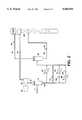
- FIG. 1is a schematic flow diagram, showing a preferred embodiment of the invention, the broken lines indicating several alternative schemes.
- FIG. 2is a schematic flow diagram showing specific aspects of the invention including partial vaporization of liquid condensate from the first separator and the directing of the vapor components from each separator to provide refluxing agents for the demethanizer.
- feed stream 1has a temperature of about 90° F.
- temperaturemay vary depending on the source of the feed gas.
- a natural gas from a pipelinemay have a temperature between about 60° and 125° F.
- the feed or inlet streamis a multicomponent feed gas that includes light components such as methane, as well as other heavier gaseous components such as ethane, ethylene,, propylene, propane and heavier hydrocarbons.
- the feed gasmay also include non-hydrocarbon components such as carbon dioxide, nitrogen, hydrogen, and sulfides.
- the feed gasmay have a relatively high CO 2 concentration, e.g., about 1-2 mol % or more.
- the feed gasmay be natural gas or a processed gas, including refinery or synthesis gas. Prior to cooling, the feed gas may be processed in a conventional manner to remove amounts of impurities, including non-hydrocarbon components such as sulfur and carbon dioxide. Also, prior to cooling, the feed gas may be compressed and dehydrated to minimize hydrate formation during the process.
- the feed gas of stream 1may be split or divided into two streams 2 and 3 both having the same composition as stream 1.
- stream 3may be processed in a variety of ways to take advantage of the heat transfer capabilities inherently possessed by the feed gas, which typically has a higher temperature than other streams in the process.
- stream 2is cooled in heat exchanger 8 to a lower temperature, which for illustrative purposes may range from about -30° to -85° F., for example, -64° F.
- this cooling stepmay be accomplished or supplemented by a chiller, series of chillers, or one or more refrigeration devices, not shown here, and may have various recycle configurations.
- the broken line in FIG. 1shows stream 2 being directed through heat exchanger 13 in heat exchange relation with stream 38.
- a single heat exchanger 8is used to accomplish the heating and cooling of the various streams, particularly the initial cooling of the feed gas stream 2 and the heating of the expanded liquid condensate 26 coming from the high pressure separator.
- a conventional plate-fin exchangermay be used for this purpose.
- the various streamsincluding output streams from the separators, and in particular streams 2, 26, and 38, are preferably positioned in heat exchange relation to provide cooling and heating in the heat exchanger 8.
- the warmer stream 2may be cooled by transferring heat to cooler stream 26, which may thereby be heated prior to entering separator 30.
- the cooled feed stream 4is fed to a separator 6, which may be a conventional gas-liquid separation device.
- the cooling of streams 2 and 3causes partial condensation, so that stream 4 is a two-phase stream.
- stream 4may be separated into a vapor stream 16, which is at least predominantly vapor, and a liquid stream 18, which is at least predominantly liquid.
- FIG. 1shows that stream 4 is separated immediately after cooling, it will be recognized by persons skilled in the art that additional processing of stream 4 may take place before its introduction to the separator 6, including one or more separations and/or cooling steps.
- the cooling step in FIG. 1is shown as being separate from the separation step, it is contemplated that cooling and separation may be accomplished in a single device.
- the vapor stream 16 exiting the separator 6has a first composition, which is typically predominantly methane and which may vary depending on the source of the feed gas and other factors, such as the conditions at which the separator is operated.
- the liquid stream 18 exiting the separator 6has a second composition and typically has a higher concentration of heavier components than the feed stream.
- the separator 6,which may be referred to herein as the "first separator” or “high pressure separator,” operates at a relatively high pressure, preferably the pressure of the inlet feed gas, which may be provided from a pipeline or other source of pressurized gas.
- the pressure in separator 6may range from about 450 to 1350 psig, an illustrative pressure being about 835 psig.
- the vapor stream 16 from the high pressure separator 6is preferably directed to a demethanizer 36.
- demethanizerrefers broadly to any device that can remove methane from a feed gas, including what is often referred to as a "deethanizer,” which is designed to remove both methane and ethane.
- the demethanizer 36is shown in FIG. 1 as a demethanizing column, it may also include any distillation device or apparatus capable of removing methane from a feed gas by application of heat, including distillation, rectification, and fractionation columns or towers. Where a demethanizing column is used, it may have different numbers of trays or levels, depending on overall design, efficiencies and optimization consideration.
- stream 16containing a light fraction of the original feed gas, preferably passes through an expander 20 where the pressure and temperature are reduced.
- expansion devicesuch as an expansion valve, or any other work expansion machine or engine that is capable of lowering the pressure of a hydrocarbon stream.
- the expander 20reduces the pressure of the vapor stream to, for example, the operating pressure of the demethanizer 36, which preferably ranges from about 160 to 490 psig. Additionally, the temperature may be reduced to a range of from about -70° to -180° F., for example, to about -135° F., which in a specific embodiment is the temperature at which it enters the demethanizer 36.
- the stream 22 from expander 20preferably then flows into the demethanizer column 36 at some midway point, defined herein as a point on the demethanizer lower than the point at which the vapor portion from the second separator 30 enters the demethanizer 36 (discussed below).
- Condensed liquid stream 18exits separator 6. Although not shown, it may be desirable under certain circumstances to divert a portion of the liquid stream 18 to some other part of the process or system. However, at least a portion of the liquid stream from the high pressure separator 6 should be reduced in pressure in controlled expansion valve 24, preferably to a pressure of the intermediate separator 30. Accordingly, a partial vaporization of the liquid stream 18 may be accomplished to provide a two-phase stream 26.
- the stream 26 from the controlled expansion valve 24may be heated, for example, in heat exchanger 8, to further vaporize light hydrocarbon components in the liquid portion of stream 26.
- the broken lines in FIG. 1show alternative embodiments including one in which the expanded stream 26 is positioned in heat exchange relation with stream 11 in exchanger 9.
- the inventioncontemplates a variety of configurations to provide partial vaporization of at least a portion of the liquid condensate stream discharged from the separator 6.
- FIG. 2which uses corresponding reference numbers, there are at least four alternative configurations by which the liquid condensate from separator 6 may be partially vaporized.
- the portion 50 of the liquid condensate that is to be partially vaporized(which corresponds to stream 18 in FIG. 1) may be heated and thus partially vaporized in heat exchanger 52.
- stream 50is partially vaporized by expansion in an expansion valve 54.
- stream 50is first passed through expansion valve 56, which provides partial vaporization, then heated in exchanger 58 to provide additional vaporization.
- stream 50is first heated in exchanger 60 to provide partial vaporization followed by additional vaporization in expansion valve 62.
- stream 26is placed in heat exchange relation with warmer feed stream 2 in heat exchanger 8.
- the temperature of stream 26is preferably elevated about 20° to 50° F. so that, for example, the temperature in the intermediate pressure separator 30 is about -40° F.
- other heating devicesmay also be used instead of or in addition to heat exchanger 8, including, for example, heat exchanger 9.
- the lighter components of the condensate from the high pressure separator 6may thus be separated from the heavier components in an intermediate pressure separator 30 prior to introduction to the demethanizer 36.
- this aspectmay provide for both an enhanced reflux stream and more precise fractionation, particularly in an ethane recovery process, in separating methane from C 2 components.
- the two-phase stream 26passes into the vapor-liquid separation device or separator 30, referred to herein as the "medium” or “intermediate” or “second” pressure separator, which is preferably operated at a lower pressure than the high pressure separator 6.
- a desirable feature of this inventionis use of an intermediate pressure separator 30 in conjunction with a high pressure separator 6.
- the intermediate pressure separator 30is operated at a pressure ranging broadly between the pressure in the high pressure separator 6 and the operating pressure of the demethanizer 36.
- the pressure in separator 6may be about 835 psig
- the pressure in separator 30may be about 500 psig and the pressure of demethanizer 36 about 300 psig.
- An illustrative pressure range for the intermediate pressure separator 30is between about 160 and 1350 psig, and more preferably between about 300 and 700 psig.
- the precise pressure selected for the intermediate pressure separator 30 and the temperature to which stream 26 is heatedwill depend on overall design considerations, and may be determined by persons skilled in the design and/or operation of cryogenic processes.
- the vapor stream 32 from separator 30is directed to the demethanizer 36, and is preferably condensed, either totally or partially.
- condensationmay be accomplished by passing the stream 32 through any conventional condensation device, to condense most of the vapor before passing it through the controlled expansion valve 34, where the pressure of that stream is reduced to, preferably, the operating pressure of the demethanizer 36.
- Stream 32may also be reduced in temperature, preferably by passing it through heat exchanger 8. In a specific embodiment, that temperature may be about -152° F. Preferably, that temperature is lower than the temperature of the stream 22 being introduced to the demethanizer 36.
- Stream 32may then be fed to the demethanizer 36, preferably as a top feed relative to stream 22.
- Vapor stream 32has a third composition that is different from the first and second compositions mentioned earlier.
- vapor stream 32is used as an enhanced refluxing agent, having a relatively high methane concentration.
- the liquid condensate 18 discharged from the high pressure separator 6typically includes dissolved methane. The partial vaporization of that liquid condensate as discussed above, by heating and/or expansion, results in a two-phase stream 26 that includes a vapor component having a high concentration of the methane that was formerly dissolved in the condensate 18.
- vapor componentpreferably becomes stream 32, which has not only a high methane concentration but also a lower concentration of heavier hydrocarbons, which form part of the liquid component of the two-phase stream 26.
- a high methane concentration and low concentration of heavier hydrocarbonsare excellent characteristics for a refluxing agent.
- the stream 32is cooled in heat exchanger 8 and expanded in expansion valve 34 to reduce the pressure, thus forming a condensate with a high methane concentration.
- the condensed streamfunctions as an enhanced refluxing agent.
- the stream 32should be introduced to the demethanizer at a point above the point at which the condensed vapor portion 22 from the first separator 6 is introduced.
- the liquid methane from the enhanced reflux stream 32flows downward in the demethanizer 36, contacting the vapors rising in the demethanizer, which include vaporized heavier hydrocarbons from stream 22.
- the methane concentration of stream 32is higher than the methane concentration of stream 22.
- the enhanced reflux stream 32should increase overall recovery of ethane, by preventing vaporization of at least some ethane from stream 22, which might otherwise be vaporized in the demethanizer and lost as residual gas.
- a stream 33 from the second separator 30may also be directed to the demethanizer 36.
- stream 33is expanded in an expansion valve 35 to provide a two-phase stream, which may then be directed to an appropriate feed location in the demethanizer 36.
- the temperaturemay be reduced in the expansion valve 35 from about -40° F., the temperature in the medium pressure separator 30, to about -60° F.
- That liquid portion 33is preferably supplied as a mid-column feed to the demethanizer 36 at a point where the temperature is at high enough to avoid freezing, for example, at about -80° F. or higher.
- Residue gas stream 38 from the top of the demethanizer column 36may be used to provide cooling in the heat exchanger 8. Also, the stream 38 exiting from heat exchanger 8 may be partly compressed in a booster compressor 40, which is driven by a turboexpander 20. A compression stage 42 may also be provided, which may be driven by a supplemental power source 43 to recompress the residue gas to desired levels, for example, to meet pipeline pressure requirements.
- Stream 3may be directed in a variety of ways and configurations to transfer heat effectively among the various streams.
- stream 3may be directed to heat exchange relation with streams from the demethanizer, shown circulating through heat exchangers 10, 12 and 14. By exchanging heat with those streams, which are thereby heated and partially vaporized, stream 3 is thereby cooled and may be combined with stream 4, which has been cooled in heat exchanger 8.
- stream 11may be directed through heat exchanger 9 in heat exchange relation between a stream 26, which is a partially vaporized portion of the liquid condensate 18 from separator 6. As a consequence of passing through heat exchanger 9, the condensate 18 from separator 6 is heated while stream 11 is cooled.
- Other 10 alternative configurations, while not discussed herein,are shown by broken lines in FIG. 1. By configuring the streams in this or other manners, the overall external energy requirements of the process may be lowered.
Landscapes
- Engineering & Computer Science (AREA)
- Chemical & Material Sciences (AREA)
- Physics & Mathematics (AREA)
- Mechanical Engineering (AREA)
- Thermal Sciences (AREA)
- General Engineering & Computer Science (AREA)
- Oil, Petroleum & Natural Gas (AREA)
- Chemical Kinetics & Catalysis (AREA)
- General Chemical & Material Sciences (AREA)
- Organic Chemistry (AREA)
- Separation By Low-Temperature Treatments (AREA)
Abstract
Description
Claims (16)
Priority Applications (1)
| Application Number | Priority Date | Filing Date | Title |
|---|---|---|---|
| US08/476,835US5566554A (en) | 1995-06-07 | 1995-06-07 | Hydrocarbon gas separation process |
Applications Claiming Priority (1)
| Application Number | Priority Date | Filing Date | Title |
|---|---|---|---|
| US08/476,835US5566554A (en) | 1995-06-07 | 1995-06-07 | Hydrocarbon gas separation process |
Publications (1)
| Publication Number | Publication Date |
|---|---|
| US5566554Atrue US5566554A (en) | 1996-10-22 |
Family
ID=23893447
Family Applications (1)
| Application Number | Title | Priority Date | Filing Date |
|---|---|---|---|
| US08/476,835Expired - LifetimeUS5566554A (en) | 1995-06-07 | 1995-06-07 | Hydrocarbon gas separation process |
Country Status (1)
| Country | Link |
|---|---|
| US (1) | US5566554A (en) |
Cited By (70)
| Publication number | Priority date | Publication date | Assignee | Title |
|---|---|---|---|---|
| US5890377A (en)* | 1997-11-04 | 1999-04-06 | Abb Randall Corporation | Hydrocarbon gas separation process |
| WO1999037962A1 (en)* | 1998-01-20 | 1999-07-29 | Transcanada Pipelines Limited | Apparatus and method for demethanization and method of retrofitting an installation for liquefying gas |
| US5953935A (en)* | 1997-11-04 | 1999-09-21 | Mcdermott Engineers & Constructors (Canada) Ltd. | Ethane recovery process |
| US5956971A (en)* | 1997-07-01 | 1999-09-28 | Exxon Production Research Company | Process for liquefying a natural gas stream containing at least one freezable component |
| US5983664A (en)* | 1997-04-09 | 1999-11-16 | Elcor Corporation | Hydrocarbon gas processing |
| US5992175A (en)* | 1997-12-08 | 1999-11-30 | Ipsi Llc | Enhanced NGL recovery processes |
| US6109061A (en)* | 1998-12-31 | 2000-08-29 | Abb Randall Corporation | Ethane rejection utilizing stripping gas in cryogenic recovery processes |
| US6116050A (en)* | 1998-12-04 | 2000-09-12 | Ipsi Llc | Propane recovery methods |
| US6182469B1 (en)* | 1998-12-01 | 2001-02-06 | Elcor Corporation | Hydrocarbon gas processing |
| US6244070B1 (en) | 1999-12-03 | 2001-06-12 | Ipsi, L.L.C. | Lean reflux process for high recovery of ethane and heavier components |
| US6354105B1 (en) | 1999-12-03 | 2002-03-12 | Ipsi L.L.C. | Split feed compression process for high recovery of ethane and heavier components |
| US20020065446A1 (en)* | 2000-10-02 | 2002-05-30 | Elcor Corporation | Hydrocarbon gas processing |
| FR2817766A1 (en)* | 2000-12-13 | 2002-06-14 | Technip Cie | PROCESS AND PLANT FOR SEPARATING A GAS MIXTURE CONTAINING METHANE BY DISTILLATION, AND GASES OBTAINED BY THIS SEPARATION |
| US6425266B1 (en) | 2001-09-24 | 2002-07-30 | Air Products And Chemicals, Inc. | Low temperature hydrocarbon gas separation process |
| US6526777B1 (en) | 2001-04-20 | 2003-03-04 | Elcor Corporation | LNG production in cryogenic natural gas processing plants |
| US6604367B2 (en)* | 2001-12-19 | 2003-08-12 | Praxair Technology, Inc. | System for providing refrigeration for chemical processing |
| US20040079107A1 (en)* | 2002-10-23 | 2004-04-29 | Wilkinson John D. | Natural gas liquefaction |
| US6742358B2 (en) | 2001-06-08 | 2004-06-01 | Elkcorp | Natural gas liquefaction |
| US20040177646A1 (en)* | 2003-03-07 | 2004-09-16 | Elkcorp | LNG production in cryogenic natural gas processing plants |
| US6823692B1 (en) | 2002-02-11 | 2004-11-30 | Abb Lummus Global Inc. | Carbon dioxide reduction scheme for NGL processes |
| US20050066686A1 (en)* | 2003-09-30 | 2005-03-31 | Elkcorp | Liquefied natural gas processing |
| US20050155382A1 (en)* | 2003-07-24 | 2005-07-21 | Toyo Engineering Corporation | Process and apparatus for separation of hydrocarbons |
| US20050247078A1 (en)* | 2004-05-04 | 2005-11-10 | Elkcorp | Natural gas liquefaction |
| US20050255012A1 (en)* | 2002-08-15 | 2005-11-17 | John Mak | Low pressure ngl plant cofigurations |
| US20060000234A1 (en)* | 2004-07-01 | 2006-01-05 | Ortloff Engineers, Ltd. | Liquefied natural gas processing |
| US20060032269A1 (en)* | 2003-02-25 | 2006-02-16 | Ortloff Engineers, Ltd. | Hydrocarbon gas processing |
| US20070227186A1 (en)* | 2004-09-24 | 2007-10-04 | Alferov Vadim I | Systems and methods for low-temperature gas separation |
| US20080000265A1 (en)* | 2006-06-02 | 2008-01-03 | Ortloff Engineers, Ltd. | Liquefied Natural Gas Processing |
| US20080190136A1 (en)* | 2007-02-09 | 2008-08-14 | Ortloff Engineers, Ltd. | Hydrocarbon Gas Processing |
| US20080282731A1 (en)* | 2007-05-17 | 2008-11-20 | Ortloff Engineers, Ltd. | Liquefied Natural Gas Processing |
| US20090100862A1 (en)* | 2007-10-18 | 2009-04-23 | Ortloff Engineers, Ltd. | Hydrocarbon Gas Processing |
| US20090107175A1 (en)* | 2003-01-16 | 2009-04-30 | Patel Sanjiv N | Multiple Reflux Stream Hydrocarbon Recovery Process |
| US20100011810A1 (en)* | 2005-07-07 | 2010-01-21 | Fluor Technologies Corporation | NGL Recovery Methods and Configurations |
| US20100031700A1 (en)* | 2008-08-06 | 2010-02-11 | Ortloff Engineers, Ltd. | Liquefied natural gas and hydrocarbon gas processing |
| US20100236285A1 (en)* | 2009-02-17 | 2010-09-23 | Ortloff Engineers, Ltd. | Hydrocarbon Gas Processing |
| US20100251764A1 (en)* | 2009-02-17 | 2010-10-07 | Ortloff Engineers, Ltd. | Hydrocarbon Gas Processing |
| US20100275647A1 (en)* | 2009-02-17 | 2010-11-04 | Ortloff Engineers, Ltd. | Hydrocarbon Gas Processing |
| US20100287984A1 (en)* | 2009-02-17 | 2010-11-18 | Ortloff Engineers, Ltd. | Hydrocarbon gas processing |
| US20100287983A1 (en)* | 2009-02-17 | 2010-11-18 | Ortloff Engineers, Ltd. | Hydrocarbon Gas Processing |
| US20100326134A1 (en)* | 2009-02-17 | 2010-12-30 | Ortloff Engineers Ltd. | Hydrocarbon Gas Processing |
| US20110067442A1 (en)* | 2009-09-21 | 2011-03-24 | Ortloff Engineers, Ltd. | Hydrocarbon Gas Processing |
| US20110226013A1 (en)* | 2010-03-31 | 2011-09-22 | S.M.E. Products Lp | Hydrocarbon Gas Processing |
| US20110226011A1 (en)* | 2010-03-31 | 2011-09-22 | S.M.E. Products Lp | Hydrocarbon Gas Processing |
| US20110226014A1 (en)* | 2010-03-31 | 2011-09-22 | S.M.E. Products Lp | Hydrocarbon Gas Processing |
| US20110232328A1 (en)* | 2010-03-31 | 2011-09-29 | S.M.E. Products Lp | Hydrocarbon Gas Processing |
| US8434325B2 (en) | 2009-05-15 | 2013-05-07 | Ortloff Engineers, Ltd. | Liquefied natural gas and hydrocarbon gas processing |
| US20140060112A1 (en)* | 2012-09-04 | 2014-03-06 | Linde Aktiengesellschaft | Method for separating c2+-hydrocarbons from a hydrocarbon-rich fraction |
| US8667812B2 (en) | 2010-06-03 | 2014-03-11 | Ordoff Engineers, Ltd. | Hydrocabon gas processing |
| US8794030B2 (en) | 2009-05-15 | 2014-08-05 | Ortloff Engineers, Ltd. | Liquefied natural gas and hydrocarbon gas processing |
| US8850849B2 (en) | 2008-05-16 | 2014-10-07 | Ortloff Engineers, Ltd. | Liquefied natural gas and hydrocarbon gas processing |
| US9021832B2 (en) | 2010-01-14 | 2015-05-05 | Ortloff Engineers, Ltd. | Hydrocarbon gas processing |
| US9052137B2 (en) | 2009-02-17 | 2015-06-09 | Ortloff Engineers, Ltd. | Hydrocarbon gas processing |
| US9243842B2 (en) | 2008-02-15 | 2016-01-26 | Black & Veatch Corporation | Combined synthesis gas separation and LNG production method and system |
| WO2016053668A1 (en) | 2014-09-30 | 2016-04-07 | Dow Global Technologies Llc | Process for increasing ethylene and propylene yield from a propylene plant |
| US9574822B2 (en) | 2014-03-17 | 2017-02-21 | Black & Veatch Corporation | Liquefied natural gas facility employing an optimized mixed refrigerant system |
| US9581385B2 (en) | 2013-05-15 | 2017-02-28 | Linde Engineering North America Inc. | Methods for separating hydrocarbon gases |
| US9637428B2 (en) | 2013-09-11 | 2017-05-02 | Ortloff Engineers, Ltd. | Hydrocarbon gas processing |
| US9777960B2 (en) | 2010-12-01 | 2017-10-03 | Black & Veatch Holding Company | NGL recovery from natural gas using a mixed refrigerant |
| US9783470B2 (en) | 2013-09-11 | 2017-10-10 | Ortloff Engineers, Ltd. | Hydrocarbon gas processing |
| US9790147B2 (en) | 2013-09-11 | 2017-10-17 | Ortloff Engineers, Ltd. | Hydrocarbon processing |
| US10113127B2 (en) | 2010-04-16 | 2018-10-30 | Black & Veatch Holding Company | Process for separating nitrogen from a natural gas stream with nitrogen stripping in the production of liquefied natural gas |
| US10139157B2 (en) | 2012-02-22 | 2018-11-27 | Black & Veatch Holding Company | NGL recovery from natural gas using a mixed refrigerant |
| US10533794B2 (en) | 2016-08-26 | 2020-01-14 | Ortloff Engineers, Ltd. | Hydrocarbon gas processing |
| US10551119B2 (en) | 2016-08-26 | 2020-02-04 | Ortloff Engineers, Ltd. | Hydrocarbon gas processing |
| US10551118B2 (en) | 2016-08-26 | 2020-02-04 | Ortloff Engineers, Ltd. | Hydrocarbon gas processing |
| US10563913B2 (en) | 2013-11-15 | 2020-02-18 | Black & Veatch Holding Company | Systems and methods for hydrocarbon refrigeration with a mixed refrigerant cycle |
| US11428465B2 (en) | 2017-06-01 | 2022-08-30 | Uop Llc | Hydrocarbon gas processing |
| US11543180B2 (en) | 2017-06-01 | 2023-01-03 | Uop Llc | Hydrocarbon gas processing |
| US11578915B2 (en) | 2019-03-11 | 2023-02-14 | Uop Llc | Hydrocarbon gas processing |
| US11643604B2 (en) | 2019-10-18 | 2023-05-09 | Uop Llc | Hydrocarbon gas processing |
Citations (13)
| Publication number | Priority date | Publication date | Assignee | Title |
|---|---|---|---|---|
| US2880592A (en)* | 1955-11-10 | 1959-04-07 | Phillips Petroleum Co | Demethanization of cracked gases |
| US3292380A (en)* | 1964-04-28 | 1966-12-20 | Coastal States Gas Producing C | Method and equipment for treating hydrocarbon gases for pressure reduction and condensate recovery |
| US4171964A (en)* | 1976-06-21 | 1979-10-23 | The Ortloff Corporation | Hydrocarbon gas processing |
| US4278457A (en)* | 1977-07-14 | 1981-07-14 | Ortloff Corporation | Hydrocarbon gas processing |
| US4456461A (en)* | 1982-09-09 | 1984-06-26 | Phillips Petroleum Company | Separation of low boiling constituents from a mixed gas |
| US4507133A (en)* | 1983-09-29 | 1985-03-26 | Exxon Production Research Co. | Process for LPG recovery |
| US4519824A (en)* | 1983-11-07 | 1985-05-28 | The Randall Corporation | Hydrocarbon gas separation |
| US4617039A (en)* | 1984-11-19 | 1986-10-14 | Pro-Quip Corporation | Separating hydrocarbon gases |
| US4657571A (en)* | 1984-06-29 | 1987-04-14 | Snamprogetti S.P.A. | Process for the recovery of heavy constituents from hydrocarbon gaseous mixtures |
| US4710214A (en)* | 1986-12-19 | 1987-12-01 | The M. W. Kellogg Company | Process for separation of hydrocarbon gases |
| US4846863A (en)* | 1987-02-18 | 1989-07-11 | Costain Petrocarbon Limited | Separation of hydrocarbon mixtures |
| US4854955A (en)* | 1988-05-17 | 1989-08-08 | Elcor Corporation | Hydrocarbon gas processing |
| US4889545A (en)* | 1988-11-21 | 1989-12-26 | Elcor Corporation | Hydrocarbon gas processing |
- 1995
- 1995-06-07USUS08/476,835patent/US5566554A/ennot_activeExpired - Lifetime
Patent Citations (13)
| Publication number | Priority date | Publication date | Assignee | Title |
|---|---|---|---|---|
| US2880592A (en)* | 1955-11-10 | 1959-04-07 | Phillips Petroleum Co | Demethanization of cracked gases |
| US3292380A (en)* | 1964-04-28 | 1966-12-20 | Coastal States Gas Producing C | Method and equipment for treating hydrocarbon gases for pressure reduction and condensate recovery |
| US4171964A (en)* | 1976-06-21 | 1979-10-23 | The Ortloff Corporation | Hydrocarbon gas processing |
| US4278457A (en)* | 1977-07-14 | 1981-07-14 | Ortloff Corporation | Hydrocarbon gas processing |
| US4456461A (en)* | 1982-09-09 | 1984-06-26 | Phillips Petroleum Company | Separation of low boiling constituents from a mixed gas |
| US4507133A (en)* | 1983-09-29 | 1985-03-26 | Exxon Production Research Co. | Process for LPG recovery |
| US4519824A (en)* | 1983-11-07 | 1985-05-28 | The Randall Corporation | Hydrocarbon gas separation |
| US4657571A (en)* | 1984-06-29 | 1987-04-14 | Snamprogetti S.P.A. | Process for the recovery of heavy constituents from hydrocarbon gaseous mixtures |
| US4617039A (en)* | 1984-11-19 | 1986-10-14 | Pro-Quip Corporation | Separating hydrocarbon gases |
| US4710214A (en)* | 1986-12-19 | 1987-12-01 | The M. W. Kellogg Company | Process for separation of hydrocarbon gases |
| US4846863A (en)* | 1987-02-18 | 1989-07-11 | Costain Petrocarbon Limited | Separation of hydrocarbon mixtures |
| US4854955A (en)* | 1988-05-17 | 1989-08-08 | Elcor Corporation | Hydrocarbon gas processing |
| US4889545A (en)* | 1988-11-21 | 1989-12-26 | Elcor Corporation | Hydrocarbon gas processing |
Cited By (113)
| Publication number | Priority date | Publication date | Assignee | Title |
|---|---|---|---|---|
| US5983664A (en)* | 1997-04-09 | 1999-11-16 | Elcor Corporation | Hydrocarbon gas processing |
| US5956971A (en)* | 1997-07-01 | 1999-09-28 | Exxon Production Research Company | Process for liquefying a natural gas stream containing at least one freezable component |
| WO1999023428A1 (en)* | 1997-11-04 | 1999-05-14 | Abb Randall Corporation | Hydrocarbon gas separation process |
| US5953935A (en)* | 1997-11-04 | 1999-09-21 | Mcdermott Engineers & Constructors (Canada) Ltd. | Ethane recovery process |
| US5890377A (en)* | 1997-11-04 | 1999-04-06 | Abb Randall Corporation | Hydrocarbon gas separation process |
| US5992175A (en)* | 1997-12-08 | 1999-11-30 | Ipsi Llc | Enhanced NGL recovery processes |
| US6237365B1 (en) | 1998-01-20 | 2001-05-29 | Transcanada Energy Ltd. | Apparatus for and method of separating a hydrocarbon gas into two fractions and a method of retrofitting an existing cryogenic apparatus |
| WO1999037962A1 (en)* | 1998-01-20 | 1999-07-29 | Transcanada Pipelines Limited | Apparatus and method for demethanization and method of retrofitting an installation for liquefying gas |
| GB2351342B (en)* | 1998-01-20 | 2001-12-12 | Trans Canada Pipelines Ltd | Apparatus and method for demethanization and method of retrofitting an installation for liquefying gas |
| GB2351342A (en)* | 1998-01-20 | 2000-12-27 | Trans Canada Pipelines Ltd | Apparatus and method for demethanization and method of retrofitting an installation for liquefying gas |
| US6182469B1 (en)* | 1998-12-01 | 2001-02-06 | Elcor Corporation | Hydrocarbon gas processing |
| US6116050A (en)* | 1998-12-04 | 2000-09-12 | Ipsi Llc | Propane recovery methods |
| US6109061A (en)* | 1998-12-31 | 2000-08-29 | Abb Randall Corporation | Ethane rejection utilizing stripping gas in cryogenic recovery processes |
| US6244070B1 (en) | 1999-12-03 | 2001-06-12 | Ipsi, L.L.C. | Lean reflux process for high recovery of ethane and heavier components |
| US6354105B1 (en) | 1999-12-03 | 2002-03-12 | Ipsi L.L.C. | Split feed compression process for high recovery of ethane and heavier components |
| US20020065446A1 (en)* | 2000-10-02 | 2002-05-30 | Elcor Corporation | Hydrocarbon gas processing |
| US6915662B2 (en) | 2000-10-02 | 2005-07-12 | Elkcorp. | Hydrocarbon gas processing |
| US6578379B2 (en) | 2000-12-13 | 2003-06-17 | Technip-Coflexip | Process and installation for separation of a gas mixture containing methane by distillation |
| WO2002048627A1 (en)* | 2000-12-13 | 2002-06-20 | Technip France | Method and installation for separating a gas mixture containing methane by distillation |
| CN100389295C (en)* | 2000-12-13 | 2008-05-21 | 泰克尼普法国公司 | Process and apparatus for separating a gas mixture containing methane by distillation, and gas obtained by separation |
| FR2817766A1 (en)* | 2000-12-13 | 2002-06-14 | Technip Cie | PROCESS AND PLANT FOR SEPARATING A GAS MIXTURE CONTAINING METHANE BY DISTILLATION, AND GASES OBTAINED BY THIS SEPARATION |
| US6526777B1 (en) | 2001-04-20 | 2003-03-04 | Elcor Corporation | LNG production in cryogenic natural gas processing plants |
| US6742358B2 (en) | 2001-06-08 | 2004-06-01 | Elkcorp | Natural gas liquefaction |
| US7210311B2 (en) | 2001-06-08 | 2007-05-01 | Ortloff Engineers, Ltd. | Natural gas liquefaction |
| US7010937B2 (en) | 2001-06-08 | 2006-03-14 | Elkcorp | Natural gas liquefaction |
| US20090293538A1 (en)* | 2001-06-08 | 2009-12-03 | Ortloff Engineers, Ltd. | Natural gas liquefaction |
| US20050268649A1 (en)* | 2001-06-08 | 2005-12-08 | Ortloff Engineers, Ltd. | Natural gas liquefaction |
| US6425266B1 (en) | 2001-09-24 | 2002-07-30 | Air Products And Chemicals, Inc. | Low temperature hydrocarbon gas separation process |
| US6604367B2 (en)* | 2001-12-19 | 2003-08-12 | Praxair Technology, Inc. | System for providing refrigeration for chemical processing |
| US6823692B1 (en) | 2002-02-11 | 2004-11-30 | Abb Lummus Global Inc. | Carbon dioxide reduction scheme for NGL processes |
| US20050255012A1 (en)* | 2002-08-15 | 2005-11-17 | John Mak | Low pressure ngl plant cofigurations |
| US7713497B2 (en)* | 2002-08-15 | 2010-05-11 | Fluor Technologies Corporation | Low pressure NGL plant configurations |
| US20040079107A1 (en)* | 2002-10-23 | 2004-04-29 | Wilkinson John D. | Natural gas liquefaction |
| US6945075B2 (en) | 2002-10-23 | 2005-09-20 | Elkcorp | Natural gas liquefaction |
| US7793517B2 (en)* | 2003-01-16 | 2010-09-14 | Lummus Technology Inc. | Multiple reflux stream hydrocarbon recovery process |
| US20090107175A1 (en)* | 2003-01-16 | 2009-04-30 | Patel Sanjiv N | Multiple Reflux Stream Hydrocarbon Recovery Process |
| US20060032269A1 (en)* | 2003-02-25 | 2006-02-16 | Ortloff Engineers, Ltd. | Hydrocarbon gas processing |
| US7191617B2 (en) | 2003-02-25 | 2007-03-20 | Ortloff Engineers, Ltd. | Hydrocarbon gas processing |
| US6889523B2 (en) | 2003-03-07 | 2005-05-10 | Elkcorp | LNG production in cryogenic natural gas processing plants |
| US20040177646A1 (en)* | 2003-03-07 | 2004-09-16 | Elkcorp | LNG production in cryogenic natural gas processing plants |
| US20050155382A1 (en)* | 2003-07-24 | 2005-07-21 | Toyo Engineering Corporation | Process and apparatus for separation of hydrocarbons |
| US7357003B2 (en) | 2003-07-24 | 2008-04-15 | Toyo Engineering Corporation | Process and apparatus for separation of hydrocarbons |
| US20050066686A1 (en)* | 2003-09-30 | 2005-03-31 | Elkcorp | Liquefied natural gas processing |
| US7155931B2 (en) | 2003-09-30 | 2007-01-02 | Ortloff Engineers, Ltd. | Liquefied natural gas processing |
| US7204100B2 (en) | 2004-05-04 | 2007-04-17 | Ortloff Engineers, Ltd. | Natural gas liquefaction |
| US20050247078A1 (en)* | 2004-05-04 | 2005-11-10 | Elkcorp | Natural gas liquefaction |
| US20060000234A1 (en)* | 2004-07-01 | 2006-01-05 | Ortloff Engineers, Ltd. | Liquefied natural gas processing |
| US7216507B2 (en) | 2004-07-01 | 2007-05-15 | Ortloff Engineers, Ltd. | Liquefied natural gas processing |
| US20070227186A1 (en)* | 2004-09-24 | 2007-10-04 | Alferov Vadim I | Systems and methods for low-temperature gas separation |
| US20100011810A1 (en)* | 2005-07-07 | 2010-01-21 | Fluor Technologies Corporation | NGL Recovery Methods and Configurations |
| US7631516B2 (en) | 2006-06-02 | 2009-12-15 | Ortloff Engineers, Ltd. | Liquefied natural gas processing |
| US20080000265A1 (en)* | 2006-06-02 | 2008-01-03 | Ortloff Engineers, Ltd. | Liquefied Natural Gas Processing |
| US20080190136A1 (en)* | 2007-02-09 | 2008-08-14 | Ortloff Engineers, Ltd. | Hydrocarbon Gas Processing |
| US8590340B2 (en) | 2007-02-09 | 2013-11-26 | Ortoff Engineers, Ltd. | Hydrocarbon gas processing |
| US20080282731A1 (en)* | 2007-05-17 | 2008-11-20 | Ortloff Engineers, Ltd. | Liquefied Natural Gas Processing |
| US9869510B2 (en) | 2007-05-17 | 2018-01-16 | Ortloff Engineers, Ltd. | Liquefied natural gas processing |
| US20090100862A1 (en)* | 2007-10-18 | 2009-04-23 | Ortloff Engineers, Ltd. | Hydrocarbon Gas Processing |
| US8919148B2 (en) | 2007-10-18 | 2014-12-30 | Ortloff Engineers, Ltd. | Hydrocarbon gas processing |
| US9243842B2 (en) | 2008-02-15 | 2016-01-26 | Black & Veatch Corporation | Combined synthesis gas separation and LNG production method and system |
| US8850849B2 (en) | 2008-05-16 | 2014-10-07 | Ortloff Engineers, Ltd. | Liquefied natural gas and hydrocarbon gas processing |
| US20100031700A1 (en)* | 2008-08-06 | 2010-02-11 | Ortloff Engineers, Ltd. | Liquefied natural gas and hydrocarbon gas processing |
| US20110120183A9 (en)* | 2008-08-06 | 2011-05-26 | Ortloff Engineers, Ltd. | Liquefied natural gas and hydrocarbon gas processing |
| US8584488B2 (en) | 2008-08-06 | 2013-11-19 | Ortloff Engineers, Ltd. | Liquefied natural gas production |
| US20100236285A1 (en)* | 2009-02-17 | 2010-09-23 | Ortloff Engineers, Ltd. | Hydrocarbon Gas Processing |
| US20100275647A1 (en)* | 2009-02-17 | 2010-11-04 | Ortloff Engineers, Ltd. | Hydrocarbon Gas Processing |
| US9939195B2 (en) | 2009-02-17 | 2018-04-10 | Ortloff Engineers, Ltd. | Hydrocarbon gas processing including a single equipment item processing assembly |
| US9939196B2 (en) | 2009-02-17 | 2018-04-10 | Ortloff Engineers, Ltd. | Hydrocarbon gas processing including a single equipment item processing assembly |
| US9933207B2 (en) | 2009-02-17 | 2018-04-03 | Ortloff Engineers, Ltd. | Hydrocarbon gas processing |
| US20100251764A1 (en)* | 2009-02-17 | 2010-10-07 | Ortloff Engineers, Ltd. | Hydrocarbon Gas Processing |
| US20100287984A1 (en)* | 2009-02-17 | 2010-11-18 | Ortloff Engineers, Ltd. | Hydrocarbon gas processing |
| US9021831B2 (en) | 2009-02-17 | 2015-05-05 | Ortloff Engineers, Ltd. | Hydrocarbon gas processing |
| US20100326134A1 (en)* | 2009-02-17 | 2010-12-30 | Ortloff Engineers Ltd. | Hydrocarbon Gas Processing |
| US9080811B2 (en) | 2009-02-17 | 2015-07-14 | Ortloff Engineers, Ltd | Hydrocarbon gas processing |
| US9052137B2 (en) | 2009-02-17 | 2015-06-09 | Ortloff Engineers, Ltd. | Hydrocarbon gas processing |
| US8881549B2 (en) | 2009-02-17 | 2014-11-11 | Ortloff Engineers, Ltd. | Hydrocarbon gas processing |
| US20100287983A1 (en)* | 2009-02-17 | 2010-11-18 | Ortloff Engineers, Ltd. | Hydrocarbon Gas Processing |
| US8794030B2 (en) | 2009-05-15 | 2014-08-05 | Ortloff Engineers, Ltd. | Liquefied natural gas and hydrocarbon gas processing |
| US8434325B2 (en) | 2009-05-15 | 2013-05-07 | Ortloff Engineers, Ltd. | Liquefied natural gas and hydrocarbon gas processing |
| US9476639B2 (en) | 2009-09-21 | 2016-10-25 | Ortloff Engineers, Ltd. | Hydrocarbon gas processing featuring a compressed reflux stream formed by combining a portion of column residue gas with a distillation vapor stream withdrawn from the side of the column |
| US20110067442A1 (en)* | 2009-09-21 | 2011-03-24 | Ortloff Engineers, Ltd. | Hydrocarbon Gas Processing |
| US20110067443A1 (en)* | 2009-09-21 | 2011-03-24 | Ortloff Engineers, Ltd. | Hydrocarbon Gas Processing |
| US9021832B2 (en) | 2010-01-14 | 2015-05-05 | Ortloff Engineers, Ltd. | Hydrocarbon gas processing |
| US9057558B2 (en) | 2010-03-31 | 2015-06-16 | Ortloff Engineers, Ltd. | Hydrocarbon gas processing including a single equipment item processing assembly |
| US9068774B2 (en) | 2010-03-31 | 2015-06-30 | Ortloff Engineers, Ltd. | Hydrocarbon gas processing |
| US9074814B2 (en) | 2010-03-31 | 2015-07-07 | Ortloff Engineers, Ltd. | Hydrocarbon gas processing |
| US20110232328A1 (en)* | 2010-03-31 | 2011-09-29 | S.M.E. Products Lp | Hydrocarbon Gas Processing |
| US9052136B2 (en) | 2010-03-31 | 2015-06-09 | Ortloff Engineers, Ltd. | Hydrocarbon gas processing |
| US20110226013A1 (en)* | 2010-03-31 | 2011-09-22 | S.M.E. Products Lp | Hydrocarbon Gas Processing |
| US20110226011A1 (en)* | 2010-03-31 | 2011-09-22 | S.M.E. Products Lp | Hydrocarbon Gas Processing |
| US20110226014A1 (en)* | 2010-03-31 | 2011-09-22 | S.M.E. Products Lp | Hydrocarbon Gas Processing |
| US10113127B2 (en) | 2010-04-16 | 2018-10-30 | Black & Veatch Holding Company | Process for separating nitrogen from a natural gas stream with nitrogen stripping in the production of liquefied natural gas |
| US8667812B2 (en) | 2010-06-03 | 2014-03-11 | Ordoff Engineers, Ltd. | Hydrocabon gas processing |
| US9777960B2 (en) | 2010-12-01 | 2017-10-03 | Black & Veatch Holding Company | NGL recovery from natural gas using a mixed refrigerant |
| US10139157B2 (en) | 2012-02-22 | 2018-11-27 | Black & Veatch Holding Company | NGL recovery from natural gas using a mixed refrigerant |
| US20140060112A1 (en)* | 2012-09-04 | 2014-03-06 | Linde Aktiengesellschaft | Method for separating c2+-hydrocarbons from a hydrocarbon-rich fraction |
| US9581385B2 (en) | 2013-05-15 | 2017-02-28 | Linde Engineering North America Inc. | Methods for separating hydrocarbon gases |
| US9790147B2 (en) | 2013-09-11 | 2017-10-17 | Ortloff Engineers, Ltd. | Hydrocarbon processing |
| US9927171B2 (en) | 2013-09-11 | 2018-03-27 | Ortloff Engineers, Ltd. | Hydrocarbon gas processing |
| US9783470B2 (en) | 2013-09-11 | 2017-10-10 | Ortloff Engineers, Ltd. | Hydrocarbon gas processing |
| US9637428B2 (en) | 2013-09-11 | 2017-05-02 | Ortloff Engineers, Ltd. | Hydrocarbon gas processing |
| US10227273B2 (en) | 2013-09-11 | 2019-03-12 | Ortloff Engineers, Ltd. | Hydrocarbon gas processing |
| US10793492B2 (en) | 2013-09-11 | 2020-10-06 | Ortloff Engineers, Ltd. | Hydrocarbon processing |
| US10563913B2 (en) | 2013-11-15 | 2020-02-18 | Black & Veatch Holding Company | Systems and methods for hydrocarbon refrigeration with a mixed refrigerant cycle |
| US9574822B2 (en) | 2014-03-17 | 2017-02-21 | Black & Veatch Corporation | Liquefied natural gas facility employing an optimized mixed refrigerant system |
| WO2016053668A1 (en) | 2014-09-30 | 2016-04-07 | Dow Global Technologies Llc | Process for increasing ethylene and propylene yield from a propylene plant |
| US10808999B2 (en) | 2014-09-30 | 2020-10-20 | Dow Global Technologies Llc | Process for increasing ethylene and propylene yield from a propylene plant |
| US10551118B2 (en) | 2016-08-26 | 2020-02-04 | Ortloff Engineers, Ltd. | Hydrocarbon gas processing |
| US10551119B2 (en) | 2016-08-26 | 2020-02-04 | Ortloff Engineers, Ltd. | Hydrocarbon gas processing |
| US10533794B2 (en) | 2016-08-26 | 2020-01-14 | Ortloff Engineers, Ltd. | Hydrocarbon gas processing |
| US11428465B2 (en) | 2017-06-01 | 2022-08-30 | Uop Llc | Hydrocarbon gas processing |
| US11543180B2 (en) | 2017-06-01 | 2023-01-03 | Uop Llc | Hydrocarbon gas processing |
| US11578915B2 (en) | 2019-03-11 | 2023-02-14 | Uop Llc | Hydrocarbon gas processing |
| US11643604B2 (en) | 2019-10-18 | 2023-05-09 | Uop Llc | Hydrocarbon gas processing |
Similar Documents
| Publication | Publication Date | Title |
|---|---|---|
| US5566554A (en) | Hydrocarbon gas separation process | |
| US5890377A (en) | Hydrocarbon gas separation process | |
| US7257966B2 (en) | Internal refrigeration for enhanced NGL recovery | |
| US6354105B1 (en) | Split feed compression process for high recovery of ethane and heavier components | |
| US5275005A (en) | Gas processing | |
| US9541329B2 (en) | Cryogenic process utilizing high pressure absorber column | |
| KR101120324B1 (en) | Hydrocarbon gas processing | |
| US9939195B2 (en) | Hydrocarbon gas processing including a single equipment item processing assembly | |
| US4707170A (en) | Staged multicomponent refrigerant cycle for a process for recovery of C+ hydrocarbons | |
| KR100939053B1 (en) | Integrated ngl recovery and liquefied natural gas production | |
| KR101619563B1 (en) | Hydrocarbon gas processing | |
| US4720293A (en) | Process for the recovery and purification of ethylene | |
| US7069744B2 (en) | Lean reflux-high hydrocarbon recovery process | |
| US9933207B2 (en) | Hydrocarbon gas processing | |
| CA2145015C (en) | Hybrid condensation-absorption olefin recovery | |
| US20020157538A1 (en) | Cryogenic process utilizing high pressure absorber column | |
| EP1743129A1 (en) | Hydrocarbon recovery process utilizing enhanced reflux streams | |
| KR20100085980A (en) | Hydrocarbon gas processing | |
| WO2000034724A1 (en) | Improved propane recovery methods | |
| NO158478B (en) | PROCEDURE FOR SEPARATING NITROGEN FROM NATURAL GAS. | |
| EP1137616B1 (en) | Low temperature separation of hydrocarbon gas | |
| KR101680923B1 (en) | Hydrocarbon gas processing | |
| KR101714102B1 (en) | Hydrocarbon gas processing | |
| KR101758394B1 (en) | Hydrocarbon gas processing | |
| KR101676069B1 (en) | Hydrocarbon gas processing |
Legal Events
| Date | Code | Title | Description |
|---|---|---|---|
| AS | Assignment | Owner name:KTI FISH INC., TEXAS Free format text:ASSIGNMENT OF ASSIGNORS INTEREST;ASSIGNORS:VIJAYARAGHAVAN, BHARAT;OSTASZEWSKI, RICARDO J.;REEL/FRAME:007578/0730 Effective date:19950608 | |
| STCF | Information on status: patent grant | Free format text:PATENTED CASE | |
| FEPP | Fee payment procedure | Free format text:PAYOR NUMBER ASSIGNED (ORIGINAL EVENT CODE: ASPN); ENTITY STATUS OF PATENT OWNER: LARGE ENTITY | |
| FEPP | Fee payment procedure | Free format text:PAYER NUMBER DE-ASSIGNED (ORIGINAL EVENT CODE: RMPN); ENTITY STATUS OF PATENT OWNER: LARGE ENTITY Free format text:PAYOR NUMBER ASSIGNED (ORIGINAL EVENT CODE: ASPN); ENTITY STATUS OF PATENT OWNER: LARGE ENTITY | |
| FPAY | Fee payment | Year of fee payment:4 | |
| FEPP | Fee payment procedure | Free format text:PAYER NUMBER DE-ASSIGNED (ORIGINAL EVENT CODE: RMPN); ENTITY STATUS OF PATENT OWNER: LARGE ENTITY Free format text:PAYOR NUMBER ASSIGNED (ORIGINAL EVENT CODE: ASPN); ENTITY STATUS OF PATENT OWNER: LARGE ENTITY | |
| FPAY | Fee payment | Year of fee payment:8 | |
| FPAY | Fee payment | Year of fee payment:12 |