US5566383A - Drive platform assembly with rotatable mounting brackets and automatic grounding bracket - Google Patents
Drive platform assembly with rotatable mounting brackets and automatic grounding bracketDownload PDFInfo
- Publication number
- US5566383A US5566383AUS08/406,777US40677795AUS5566383AUS 5566383 AUS5566383 AUS 5566383AUS 40677795 AUS40677795 AUS 40677795AUS 5566383 AUS5566383 AUS 5566383A
- Authority
- US
- United States
- Prior art keywords
- drive platform
- drive
- recited
- platform
- platform assembly
- Prior art date
- Legal status (The legal status is an assumption and is not a legal conclusion. Google has not performed a legal analysis and makes no representation as to the accuracy of the status listed.)
- Expired - Lifetime
Links
Images


Classifications
- G—PHYSICS
- G11—INFORMATION STORAGE
- G11B—INFORMATION STORAGE BASED ON RELATIVE MOVEMENT BETWEEN RECORD CARRIER AND TRANSDUCER
- G11B33/00—Constructional parts, details or accessories not provided for in the other groups of this subclass
- G11B33/12—Disposition of constructional parts in the apparatus, e.g. of power supply, of modules
- G11B33/125—Disposition of constructional parts in the apparatus, e.g. of power supply, of modules the apparatus comprising a plurality of recording/reproducing devices, e.g. modular arrangements, arrays of disc drives
- G11B33/127—Mounting arrangements of constructional parts onto a chassis
- G11B33/128—Mounting arrangements of constructional parts onto a chassis of the plurality of recording/reproducing devices, e.g. disk drives, onto a chassis
- G—PHYSICS
- G06—COMPUTING OR CALCULATING; COUNTING
- G06F—ELECTRIC DIGITAL DATA PROCESSING
- G06F1/00—Details not covered by groups G06F3/00 - G06F13/00 and G06F21/00
- G06F1/16—Constructional details or arrangements
- G06F1/18—Packaging or power distribution
- G06F1/183—Internal mounting support structures, e.g. for printed circuit boards, internal connecting means
- G06F1/184—Mounting of motherboards
- G—PHYSICS
- G06—COMPUTING OR CALCULATING; COUNTING
- G06F—ELECTRIC DIGITAL DATA PROCESSING
- G06F1/00—Details not covered by groups G06F3/00 - G06F13/00 and G06F21/00
- G06F1/16—Constructional details or arrangements
- G06F1/18—Packaging or power distribution
- G06F1/183—Internal mounting support structures, e.g. for printed circuit boards, internal connecting means
- G06F1/187—Mounting of fixed and removable disk drives
Definitions
- the present inventionrelates to a drive platform assembly and, more particularly, to a drive platform assembly for a personal computer for carrying both floppy disc drives and hard disc drives in a computer housing that reduces the assembly and disassembly time of the personal computer and, hence reduces the manufacturing and repair cost.
- Known personal computersgenerally include a metal drive platform for carrying both hard and floppy disc drives.
- the disc drivesare normally secured to the drive platform with suitable fasteners, for example, threaded screws to form an assembly.
- the assemblyis rigidly secured to the computer housing.
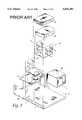
- the drive platform 21includes a generally U-shaped member defining a bight portion 23 and two depending wall portions 25 and 27.
- the length and width of the bight portion 23is selected to conveniently receive either a hard disc drive 29 or a floppy disc drive 31.
- the height of the depending wall portions 25 and 27is selected to receive either two full height disc drives, four half height disc drives or an equivalent combination of full and half height disc drives.
- the depending wall portions 25 and 27include a plurality of inwardly extending tabs 33. These inwardly extending tabs 33 enable the disc drives 29 or 31 to rest in place while they are being secured to the depending wall portions 25 and 27. More particularly, two inwardly extending tabs 33 are spaced apart and horizontally aligned at various heights along the depending wall portions 25 and 27. The locations for the extending tabs 33 are selected to correspond with the heights of full height and half height disc drives. Disposed adjacent each adjacent tab 33 are one or more unthreaded apertures 35. These apertures 35 are oriented to be aligned with corresponding threaded apertures provided in both the hard disc 29 and floppy disc drives 31.
- the hard disc drive 29 and floppy disc drive 31are shown with four threaded apertures 37.
- four unthreaded apertures 35are provided on the depending wall portions 25 and 27 so as to be aligned with the threaded apertures 37 on the hard disc and floppy disc drives 29 and 31 to enable the hard disc drives 29 and floppy disc drives 31 be secured to the depending wall portions 25 and 27 by suitable threaded fasteners 39.
- two pairs of threaded apertures 35are provided at the various half height and full height locations along each depending wall portions 25 and 26.
- the bight portion 23 of the drive platform 21may be formed with an upwardly extending tab 43 which includes an aperture 45 which enables the drive platform 21 to be secured to the front of the computer housing 41.
- additional aperturesmay be provided on the opposing end of the bight portion 23 to enable the drive platform 21 to be secured to the rear portion of the computer housing 41.
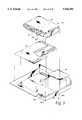
- the computer housingis normally formed to receive two full height or four half height disc drives. Accordingly, as shown in FIG. 2, two drive platforms 21 are disposed in the computer housing 41 to be aligned with an opening 43 for the disc drives; each drive platform adapted to receive either a single full height disc drive or two half height disc drives. The drive platforms 21 are then secured in place as discussed above.
- a power supply 49is disposed in the rear portion of the computer housing 40 and rigidly secured thereto.
- a motherboard 47is further secured to the computer housing 40 and appropriate electrical connection between the disc drives 29 and 31, the power supply 49 and the motherboard 47 are made.
- a problem with known drive platformsis the relative complexity and time required to assemble the disc drives 29 and 31 to the drive platform and, in turn, to the computer housing 41. Due to the number of fasteners required to secure each disc drive 29 or 31 to the drive platform 21, the complexity and time and hence the labor cost of assembly is relatively substantial. This substantial labor cost increases the price of the personal computer. In addition, such known drive platforms can increase the cost of disc drive replacement or upgrades by computer technicians.
- FIG. 1is an exploded perspective view of a known drive platform for a personal computer illustrating both a hard disc drive and a floppy disc drive;
- FIG. 2is similar to FIG. 1 and additionally illustrates a pair of drive platform assemblies, a computer housing, a motherboard and a power supply for a personal computer;
- FIG. 3is a perspective view of an assembled drive platform assembly in accordance with the present invention without any disc drives;
- FIG. 4is an exploded perspective view of a drive platform assembly in accordance with the present invention which illustrates a plurality of disc drives and a cable assembly in accordance with the present invention
- FIG. 5is an exploded perspective view illustrating a portion of a computer housing assembled with a power supply and further illustrating a motherboard and drive platform assembly with a single floppy disc drive;
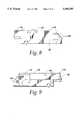
- FIG. 6is a top view of a drive platform which forms a portion of the drive platform assembly in accordance with the present invention.
- FIG. 7is an elevational view of the drive platform illustrated in FIG. 6;
- FIG. 8is a side elevational view of one side of the drive platform assembly in accordance with the present invention.
- FIG. 9is similar to FIG. 8, but illustrates the side opposite that illustrated in FIG. 8;
- FIG. 10is a rear elevational view of the drive platform in accordance with the present invention.
- FIG. 11is a bottom view of the drive platform in accordance with the present invention.
- FIG. 12is a plan view of an expansion platform which forms a portion of the drive platform assembly in accordance with the present invention.
- FIG. 13is a front elevational view of the expansion platform illustrated in FIG. 12;
- FIG. 14is a rear elevational view of the expansion platform illustrated in FIG. 12;
- FIG. 15is a bottom plan view of the expansion platform illustrated in FIG. 12;
- FIG. 16is an end view of the expansion platform illustrated in FIG. 12;
- FIG. 17is an end view of the end of the expansion platform illustrated in FIG. 12 of the end opposite that illustrated in FIG. 16;
- FIG. 18ais a perspective view of the drive platform assembly in accordance with the present invention illustrating the insertion of a floppy disc drive
- FIGS. 18b and 18care enlarged detailed views of the drive platform assembly illustrated in FIG. 18a;
- FIG. 19ais similar to FIG. 18a, but illustrates the insertion of a hard disc drive in the top bay of the drive platform;
- FIGS. 19b and 19cillustrate similar features as FIGS. 18b and 18c;
- FIG. 20aillustrates the assembly of a hard disc drive to the drive platform assembly
- FIGS. 20b and 20care similar to FIGS. 19b and 19c;
- FIG. 21ais a perspective view illustrating the insertion of the drive platform assembly in accordance with the present invention being inserted into a computer housing;
- FIG. 21bis an enlarged detailed view illustrating the securement of the front portion of the drive platform assembly in accordance with the present invention to the computer housing;
- FIGS. 22 and 23are perspective views illustrating the insertion of a drive interface board in accordance with the present invention.
- FIGS. 24 and 25are detailed views of the location and assembly of the drive interface board to the drive platform in accordance with the present invention.
- the drive platform assembly 20in accordance with the present invention includes a drive platform 22 and an expansion platform 24.
- the drive platform 22is segregated into a plurality of bays.
- the drive platform 22may be configured to define two horizontally oriented bays 26 and 28 and a stacked vertical or lower bay 30, disposed beneath one of the horizontal bays 26 or 28.
- the horizontal bay 26will hereinafter be referred to as the left bay while the other horizontal bay 28 will be referred to as the upper right bay.
- the lower bay 30will hereinafter be referred to as the lower right bay.
- the left bayis adapted to carry a floppy disc drive, for example, a 31/2 inch one-half height floppy disc drive 32.
- the right bays 28 and 30are used to carrying two 31/2 inch (one inch height) intelligent drive electronics (IDE) hard disc drives 34.
- IDEintelligent drive electronics
- the right bays 28 and 30can also be used to carry a single 1.56-inch height IDE hard disc drive.
- the expansion platform 24can be used to carry additional disc drives, such as a 51/4 inch half height hard or floppy disc drive and a 31/2 inch IDE hard disc drive. As will be discussed in more detail below, and as shown in FIG. 4, the expansion platform 24 defines two side-by-side horizontal sections defining a left section 36 and a right section 38. The expansion platform 24 is assembled to the drive platform 22 such that the left section 36 is disposed above the left bay 26 of the drive platform 22 and the right section 38 is disposed above the right bays 28 and 30 of the drive platform 22.
- additional disc drivessuch as a 51/4 inch half height hard or floppy disc drive and a 31/2 inch IDE hard disc drive.
- the expansion platform 24defines two side-by-side horizontal sections defining a left section 36 and a right section 38.
- the expansion platform 24is assembled to the drive platform 22 such that the left section 36 is disposed above the left bay 26 of the drive platform 22 and the right section 38 is disposed above the right bays 28 and 30 of the drive platform 22.
- An important aspect of the inventionis the ease in which both floppy and hard disc drives can be installed into a personal computer utilizing the drive platform assembly 20 (FIG. 3) in accordance with the present invention.
- the complexity and assembly time of the personal computeris significantly reduced which, in turn, reduces the overall cost of the computer.
- replacements and upgrades of both floppy and hard disc drivesis greatly facilitated, thus making such replacements less complicated to enable non-technical end users to replace or upgrade such drives without the need for a computer technician.
- the drive platform assembly 20(FIG. 3) includes a mounting bracket 40, suitable for mounting both hard and floppy disc drives as shown in FIG 4.
- the mounting bracket 40acts as a sub-carrier for both 31/2 inch floppy and hard disc IDE drives 32 and 34.
- the mounting bracket 40is formed as a generally U-shaped member defining a bight portion 42 and two depending sidewall portions 44 and 46. The distance between the depending sidewall portions 44 and 46 is selected to be larger than the width of both a 31/2 inch floppy disc drive and a 31/2 inch hard disc IDE drive.
- the bight portion 42is provided with a plurality of apertures 48 which are adapted to be aligned with threaded standard mounting apertures (not shown) on both 31/2 inch floppy disc drives and 31/2 inch hard disc IDE drives to enable such disc drives 32 and 34 to be rigidly secured to the mounting bracket 40 with suitable threaded fasteners 50.
- the mounting bracket 40is provided with a pair of spaced apart notches 52 and a pair of outwardly extending bosses 54 which facilitate assembly of the mounting bracket 40 to the drive platform 22 after a disc drive 32 or 34 has been assembled thereto.
- the spaced apart notches 52are utilized to secure one end of a 31/2 inch floppy disc drive 32 to the left bay 26 of the drive platform 22.
- the notches 52are spaced apart along one of the depending sidewalls 44 or 46 of the mounting bracket 40.
- the spacing between the notches 52 in the mounting bracket 40is selected to correspond with the spacing of a pair of mounting tabs 56, integrally formed in the drive platform 22.
- the mounting tabs 56are formed as generally L-shaped members and are spaced apart along one side of the left bay 26 of the drive platform 22.
- An extending leg portion 58 of the mounting tabs 56is adapted to be received within the spaced apart notches 52, formed in one of the depending sidewalls 44 or 46 of the mounting bracket 40, to secure one end of the mounting bracket 40 relative to the drive platform 22.
- the opposing end of the mounting bracket 40is secured to the drive platform 22 by an opposing pair of resiliently mounted locking tabs 60 disposed on an opposing side of the left bay 26.
- These locking tabs 60are formed with a generally L-shape having an extending leg portion 62.
- the extending leg portion 62is adapted to capture an edge of the opposing depending sidewall 44, 46 to secure the other end of the mounting bracket 40 relative to the drive platform. In particular, as shown in FIGS.
- the mounting bracket 40 with a disc drive 32 or 34 assembled theretois secured to the drive platform 22 by disposing the assembly 63 at an angle relative to the plane of the drive platform 22 such that the extending portions 58 of the L-shaped mounting tabs 56 are received in the spaced apart notches 52.
- the assembly 63is then rotated counterclockwise (FIGS. 18a-18c) about an axis generally parallel with a longitudinal axis 65 to bring the opposing sidewall 44 or 46 toward the plane of the drive platform 22.
- the L-shaped locking tabs 60are formed from a resilient material which enables them to bend outwardly as the mounting bracket 40 is being rotated in position.
- the L-shaped locking tabs 60snap back in place as their respective extending leg portions 62 clear the edge of the depending sidewall 44 to secure the assembly 63 relative to the drive platform 22.
- the outwardly extending bosses 54 on the mounting bracket 40are used to secure 31/2 inch hard disc IDE drives 34 to the drive platform 22.
- the outwardly extending bosses 54are disposed on opposing depending sidewalls 44 and 46, adjacent one end. These bosses 54, as shown in FIG. 19a, are oriented to be received in generally U-shaped slots 64 disposed in the rear portion of the upper and lower right bays 28 and 30 of the drive platform 22.
- the bosses 54form a pivot axis 67, generally perpendicular to the longitudinal axis 65, which enables the assemblies 63 to be rotated and snapped in place in a similar manner as the floppy disc drives.
- the drive platform 22includes a pair of oppositely disposed locking tabs 66.
- These locking tabs 66are resiliently mounted and formed in a generally L-shape with an extending portion 68.
- the locking tabs 66are bent outwardly by the assembly 63.
- the bosses 54function to capture the rear portion of the depending sidewalls 44 and 46 to secure the assembly 63 relative to the drive platform 22.
- the drive interface board 70includes a printed circuit board 72 along with a plurality of ribbon cables 74 connected thereto which, in turn, are connected to electrical connectors 76 which facilitate connection of the disc drives, for example 32 and 34, to the motherboard 47 and power supply 49, as shown in FIG. 5.
- the LED assembly 82includes an electrical connector 84, a plurality of LEDs 86 connected to the electrical connector 84 by way of individual electrical conductors 88.
- the LED assembly 82is adapted to be connected to the drive interface board 70.
- One LED 86is used to indicate when a hard disc drives is being accessed. In particular, these LEDs 86 are illuminated during drive accesses both during the power-on self test as well as during normal drive accesses.
- the other LED 86is used to indicate a power-on condition. LEDs for the floppy disc drives are self-contained.
- the drive platform 22may be an integrally molded device formed from an electrically insulated material such as acrylonitrile butadiene styrene (ABS).
- the left bay 26is formed in a generally U-shape defining a floor portion 90 and two spaced apart sidewalls 92 and 94; generally perpendicular to the floor portion 90.
- the left bay 26includes a pair of spaced apart locking tabs 60. These locking tabs 60 are disposed generally perpendicular to the floor portion 90 and are equally spaced from the sidewall 92.
- Disposed opposite the locking tabs 60are the mounting tabs 56. These mounting tabs 56 are spaced apart and equally spaced from the sidewall 94 to correspond with the respective spaced apart notches 52 on the mounting bracket 40.
- the right bays 28 and 30are used for hard disc drives and, in particular, for IDE drives.
- the right bays 28 and 30include the sidewall 94 and another spaced apart sidewall 96. Both sidewalls 94 and 96 are formed to extend below the floor portion 90 of the left bay 26.
- the right bays 28 and 30are adapted to receive two one-inch height or one 1.56-inch height IDE-type hard disc drives 34. As shown in FIGS. 19a-19c, these drives 34 are installed in the bays 28 and 30 in part by rotation about the axis 65, generally perpendicular to the plane of the sidewalls 94 and 96. As such, each of the top and bottom bays 28 and 30 are provided with U-shaped slots 64, adapted to receive the extending bosses 54 formed in the mounting bracket 40. Once the hard disc drive 34 is assembled to the mounting bracket 40, the extending bosses 54 are disposed in the opposing U-shaped slots 64 formed in the depending sidewalls 94 and 96.
- the drive platform 22can remain connected to the main housing.
- the extending bosses 54 from the mounting bracket 40are disposed in the opposing U-shaped slots 64 at the rear of the upper right bay 28.
- a pair of horizontal stops 98are formed on the inner faces of the sidewalls 94 and 96. These horizontal stops 98 are integrally formed as generally horizontal bar-like members and function to carry the edges of the mounting bracket 40 when the mounting bracket 40 is rotated into place.
- the assembly 63is secured relative to the right upper bay 28 by way of the pair of resiliently mounted locking tabs 66, integrally formed in the opposing sidewalls 94 and 96.
- These locking tabs 66include an extending portion 68.
- the lower right bay 30similarly includes a pair of slots 64 or apertures to enable an assembly 63 to be rotated into place about the axis 67.
- a pair of resiliently mounted locking tabs 104is formed in the lower right bay 30.
- These locking tabs 104also include an extending portion 106 which causes the locking tabs 104 to be bent outwardly when the extending portion 106 engages the mounting bracket 40 as it is rotated into place. In this situation, once the mounting bracket 40 is in place, the extending portion 106 captures the mounting bracket 40.
- a pair of cutouts 108are formed on opposing edges of the mounting bracket 40, adjacent the end opposite the bosses 54. Disposed within the cutouts are integrally formed tabs 110 that are adapted to engage the extending portions 106 of the locking tabs 104 to secure the mounting bracket 40 and thus the assembly 63 relative to the lower right bay 30.
- a plurality of vertical stops 112are formed in the depending sidewalls 94 and 96 to limit movement of the mounting bracket 40 in the lower right bay 30.
- these horizontal stops 112are adapted to engage the opposing edges of the depending sidewalls 44 and 46 of the mounting bracket 40.
- these stops 112may be formed as generally rectangular members integrally formed and extending from the stops 98 in a generally perpendicular direction.
- a hard disc driveneeds to be either replaced or installed in the lower right bay 30
- provisionsare made for removing the drive platform 22.
- floppy disc drives or hard disc drivesare either installed or replaced in the left bay 26 or the upper right bay 28, these drives can be installed in the drive platform 22 with the drive platform 22 in place.
- the drive platform 22must be removed from the computer housing. Referring now to FIGS. 4 and 6 order to facilitate removal of the drive platform 22, a pair of mounting flanges 114 are mounted on a rear portion of the drive platform 22. These mounting flanges 114 are formed with centrally disposed apertures 116.
- These apertures 116are adapted to be aligned with corresponding threaded apertures 118 (FIG. 5) in a base portion 220 of the computer housing 41 to enable the drive platform 22 to be secured thereto by way of suitable threaded fasteners 124 (FIG. 4).
- These flanges 114may also be used to secure other components to the base 220, such as the computer motherboard 126.
- the motherboard 126may be provided with suitable apertures (not shown), adapted to be aligned with the apertures 116 and 118 to enable the motherboard 126 to be secured to the base portion 220 along with the drive platform 22.
- front portion of the right bays 28 and 30 of the drive platform 22includes provisions for easily and conveniently releasably securing the front portion of the drive platform 22 to the computer housing 41.
- a depending sidewall 128is integrally formed between the depending sidewalls 94 and 96.
- This depending sidewall 128extends below the floor 90 and is formed with a resiliently mounted locking tab 130, formed with an extending portion 132.
- This locking tab 130may be formed in part by providing parallel spaced notches 134 in the depending sidewall 128. By extending these notches 134 a substantial distance along the height of the depending sidewall 128, the resilient locking tab 130 is formed.
- the extending portion 132 of the locking tab 130is adapted to be received in an aperture 136 formed in a vertically extending sidewall 138 in the base portion 220 of the computer housing 41 (FIG. 5).
- an access area 140is provided in front of the depending sidewall 128.
- This access area 140is generally formed as an extension of the floor 90 with a step portion 142.
- This step portion 142easily enables an end user to engage the locking tab 130 to disengage it from the aperture 136, formed in the vertically extending sidewall portion 138 of the base portion 220 of the computer housing 41.
- the base portion 220 of the computer housing 41needs to be exposed. Once exposed, the cables and attached connectors can be disconnected from the various drives carried by the drive platform 22. Subsequently, the threaded fasteners 124 (FIG. 4) are removed and the extending portion 132 of the locking tab 130 is disengaged from the base portion 220 of the computer housing. The drive platform 22 is then relatively easily and conveniently removed in order to enable a hard disc drive to be installed in the lower right bay 30.
- the drive platform 22also includes provision for carrying the LEDs 86 for the various drives carried by the platform 22.
- the sidewall 92is integrally formed with an extending portion 144 disposed generally perpendicularly thereto at the front of the platform 22. This extending portion 144 may be provided with an aperture 146 for carrying a LED 86.
- the extending sidewall 94is integrally formed with an outwardly extending portion with an aperture 150 for carrying another LED 86 for any hard disc drives carried by the drive platform 22.
- the LEDs 86form part of an LED assembly 82 which, in turn, is driven by the drive interface board 70 (FIGS. 22-23).
- the drive interface board 70is carried underneath the left bay 28, adjacent the sidewall 94.
- a generally rectangular slot 152is formed in the floor 90 adjacent the sidewall 94 (FIG. 11). This slot 152 is used to receive a portion of the drive interface board 70 and also enable a ribbon cable 74 for any floppy disc drive installed in the left bay 28 to be disposed on top of the floor 90.
- the drive platform 22also includes provisions for quick and easy mounting of the drive interface board 70.
- an inwardly facing stud 154is integrally formed on a lower portion of the depending sidewall 94 beneath the floor 90.
- This stud 154(FIG. 6) is adapted to be received in a corresponding aperture 156 formed in the drive interface board 70.
- Another locking tab 158is formed opposite the extending stud 154 on the lower portion of the depending sidewall 94.
- This locking tab 158includes a slot 160 for receiving an edge of the printed circuit board 72 forming a portion of the drive interface board 70.
- This slot 160is formed on an extending member 162 formed to be generally perpendicular to the depending sidewall 94.
- This extending member 162is formed with a bevelled portion 164 which facilitates mounting of the drive interface board 70 at the factory.
- the extending member 162is free on two ends.
- the stud 154is inserted into the aperture 156 on the printed circuit board 72.
- the printed circuit board 72is then rotated in a generally counter clockwise direction.
- the extending member 162bends outwardly until one corner of the printed circuit board 72 rests in the slot 160.
- a guide 166may be formed on the underside of the floor 90.
- the guide 166may be integrally formed as two parallel and spaced apart elongated bar portions, spaced apart slightly more than the width of the printed circuit board 72.
- the guide 166also enables the printed circuit board 72 to be captured or secured on three ends.
- an expansion ground bracket 168is provided.
- This bracket 168may be integrally formed and adapted to provide a ground connection between the various mounting brackets 40 (FIG. 4) installed on the drive platform 22.
- the ground bracket 168also provides a ground connection to the base portion 220 of the computer housing 41.
- the expansion platform 24is adapted to be relatively easily secured to the drive platform 22 while at the same time providing expansion capabilities for carrying additional drives.
- the expansion platform 24is formed as a generally rectangular member formed with a plurality of sets of apertures 170 and 172, appropriately spaced apart for securing additional drives thereto.
- the underside of the expansion platform 24may be integrally formed with a plurality of ribs 174 to provide support for the weight of the disc drives.
- the set of apertures 170are disposed on the left portion 38 of the expansion platform 24 and are configured to be aligned with the mounting holes (not shown) in a 51/4 inch hard disc drive or floppy disc drive.
- the set of apertures 172 disposed on the right portion 40 of the expansion platform 24are configured to be aligned with the mounting holes (not shown) for a 31/2 inch IDE hard disc drive.
- the expansion platform 24, shown in FIG. 12,is relatively easily secured to the drive platform 22.
- projections 176are formed on the top edges of the depending sidewalls 92, 94 and 96 of the drive platform 22. These projections 176 may be formed as truncated cones, for example. Referring now to FIGS. 14-17 projections 176 are adapted to be received in corresponding receptacles 178, integrally formed on the underside of the expansion platform 24.
- a pair of oppositely disposed locking tabs 180 with extending portions 182are formed on the underside of the expansion platform 24.
- locking tabs 180are disposed on opposing edges of the expansion platform 24 and are adapted to be aligned with opposing notches 184 (FIGS. 8-9)formed on the outward portion of the depending sidewalls 92 and 94. As shown in FIG. 9, the locking tabs 180 may be formed with a bevelled portion 186 which enables the locking tabs 180 to be bent outwardly in order to release the expansion platform 24 from the drive platform 22 (FIG. 3). Once the expansion platform 24 is released and removed, hard or floppy disc drives may be secured thereto rather quickly and easily by aligning the mounting holes in the particular drive with the appropriate set of apertures 170 or 172 in the expansion platform 24 (FIG. 15).
- Suitable fastenersare then used to secured the particular drive to the expansion platform 24.
- the assemblymay be rather quickly and easily be assembled to the drive platform 22 by aligning the projections 176, formed on the depending sidewalls 92, 94 and 96 of the drive platform 22 (FIGS. 9-10) with the corresponding receptacles 178 formed in the underside of the expansion platform 24 (FIG. 16). Referring to FIGS. 10 and 14-17, once the projections 176 and the receptacles 178 are aligned, the assembly is then pushed downwardly until the extending portions 182 of the locking tabs 180 are captured within the notches 184 formed in the drive platform 22.
- the expansion platformis just as easily removed.
- the expansion platform 24is removed by grasping the bevelled portion 186 of the locking tab 180 and bending it outwardly enough to disengage the extending portion 182 of the locking tab 180 from the notch 184. After the extending portion 182 is disengaged from the notch 184, the expansion platform is simply moved upwardly relative to the drive platform. In the case of a replacement of an existing disc drive, the cables 74 should be disconnected prior to removal of the expansion platform. Either a single ground clip or multiple ground clip 173 are disposed on the expansion platform 24.
Landscapes
- Engineering & Computer Science (AREA)
- Theoretical Computer Science (AREA)
- Computer Hardware Design (AREA)
- Power Engineering (AREA)
- Human Computer Interaction (AREA)
- Physics & Mathematics (AREA)
- General Engineering & Computer Science (AREA)
- General Physics & Mathematics (AREA)
- Casings For Electric Apparatus (AREA)
Abstract
Description
Claims (15)
Priority Applications (1)
| Application Number | Priority Date | Filing Date | Title |
|---|---|---|---|
| US08/406,777US5566383A (en) | 1993-04-01 | 1995-03-17 | Drive platform assembly with rotatable mounting brackets and automatic grounding bracket |
Applications Claiming Priority (2)
| Application Number | Priority Date | Filing Date | Title |
|---|---|---|---|
| US4209493A | 1993-04-01 | 1993-04-01 | |
| US08/406,777US5566383A (en) | 1993-04-01 | 1995-03-17 | Drive platform assembly with rotatable mounting brackets and automatic grounding bracket |
Related Parent Applications (1)
| Application Number | Title | Priority Date | Filing Date |
|---|---|---|---|
| US4209493AContinuation | 1993-04-01 | 1993-04-01 |
Publications (1)
| Publication Number | Publication Date |
|---|---|
| US5566383Atrue US5566383A (en) | 1996-10-15 |
Family
ID=21920011
Family Applications (1)
| Application Number | Title | Priority Date | Filing Date |
|---|---|---|---|
| US08/406,777Expired - LifetimeUS5566383A (en) | 1993-04-01 | 1995-03-17 | Drive platform assembly with rotatable mounting brackets and automatic grounding bracket |
Country Status (1)
| Country | Link |
|---|---|
| US (1) | US5566383A (en) |
Cited By (38)
| Publication number | Priority date | Publication date | Assignee | Title |
|---|---|---|---|---|
| WO1998018129A1 (en)* | 1996-10-22 | 1998-04-30 | Oce Printing Systems Gmbh | Sub-assembly for an assembly system |
| US5808864A (en)* | 1995-11-16 | 1998-09-15 | Samsung Electronics Co., Ltd. | Personal computer with disk drive mounting structure |
| US5818689A (en)* | 1996-09-30 | 1998-10-06 | Monorail, Inc. | Computer Assembly with cam member for locking components |
| WO1999059054A1 (en)* | 1998-05-13 | 1999-11-18 | Gateway 2000, Inc. | Spring clip attachment device |
| US5995364A (en)* | 1997-07-28 | 1999-11-30 | Dell Computer Corporation | Hard disk drive mounting bracket |
| US5995365A (en)* | 1997-08-04 | 1999-11-30 | Dell U.S.A. L.P. | Computer with hard disk drive carrier |
| US6097604A (en)* | 1998-12-23 | 2000-08-01 | Hewlett-Packard Company | Carrier to facilitate installation of an electronic device into an enclosure |
| US6102500A (en)* | 1999-04-20 | 2000-08-15 | Chen; Ching Mien | Computer frame assembly |
| US6122165A (en)* | 1998-11-10 | 2000-09-19 | Dell Computer Corporation | Computer with improved hard drive assembly and method for assembling same |
| US6236563B1 (en)* | 1999-06-30 | 2001-05-22 | Dell Usa, L.P. | Retention apparatus for a peripheral device |
| US6252766B1 (en) | 1999-04-21 | 2001-06-26 | Dell Usa, L.P. | Computer with peripheral device mounting assembly |
| US6262888B1 (en)* | 1999-06-30 | 2001-07-17 | Dell Usa, L.P. | Impact damping system for peripheral device |
| US6282087B1 (en) | 1998-12-15 | 2001-08-28 | Dell Usa, L.P. | Hard drive keying feature |
| US6293636B1 (en) | 1999-12-30 | 2001-09-25 | Gateway, Inc. | Device retention assembly |
| US6301099B1 (en)* | 1998-04-14 | 2001-10-09 | Compaq Computer Corporation | Computer having option card module latching and drive bay pivot structures |
| US6313984B1 (en)* | 2000-01-07 | 2001-11-06 | Mobile Storage Technology, Inc. | Low profile hard disk drive assembly mounting to computer motherboard |
| US6388876B1 (en)* | 2000-05-30 | 2002-05-14 | Hon Hai Precision Ind. Co., Ltd. | Computer enclosure incorporating pivotable drive bracket |
| US6392875B1 (en) | 2000-12-28 | 2002-05-21 | Gateway, Inc. | Hinged mounting for multiple storage drives |
| US6456489B1 (en) | 2000-05-25 | 2002-09-24 | Gateway, Inc. | Device retention apparatus |
| US6467858B1 (en) | 1999-12-23 | 2002-10-22 | Gateway, Inc. | Computer component retention tray |
| US6556433B1 (en)* | 2001-04-17 | 2003-04-29 | Gateway, Inc. | Friction fastener and method for computer components |
| US6619766B1 (en) | 1999-10-12 | 2003-09-16 | Gateway, Inc. | Device mounting and retention assembly |
| US20030202321A1 (en)* | 2002-04-30 | 2003-10-30 | Lin Wancheng | Computer enclosure incorporating drive brackets |
| US6680843B2 (en) | 2001-09-28 | 2004-01-20 | International Business Machines Corporation | All-in-one personal computer with tool-less quick-release features for various elements thereof including a reusable thin film transistor monitor |
| US20040052046A1 (en)* | 2002-09-17 | 2004-03-18 | Regimbal Laurent A. | Method and system for mounting an information handling system storage device |
| US20040075979A1 (en)* | 2002-10-22 | 2004-04-22 | Liang-Chin Wang | Computer enclosure incorporating drive barcket |
| US20040085722A1 (en)* | 2002-11-04 | 2004-05-06 | Tanzer Herbert J. | Systems for storing data |
| US20040095716A1 (en)* | 2002-11-14 | 2004-05-20 | Dell Computer Corporation | Hard drive carrier |
| US20040100761A1 (en)* | 2002-11-21 | 2004-05-27 | Dana Liu | Rotatable mechanism of removable computer peripheral device |
| US20050068720A1 (en)* | 2003-09-29 | 2005-03-31 | Lambert Jeff A. | Drive cage clutch apparatus and method |
| US6885550B1 (en) | 1999-08-26 | 2005-04-26 | Axxion Group Corporation | Screw less clip mounted computer drive |
| US20070167071A1 (en)* | 2006-01-13 | 2007-07-19 | Hon Hai Precision Industry Co., Ltd. | Mounting apparatus for circuit board |
| US20100277861A1 (en)* | 2009-04-29 | 2010-11-04 | Roesner Arlen L | Stacked Drives For A Blade System |
| US20120268889A1 (en)* | 2009-06-19 | 2012-10-25 | Kapil Rao Ganta Papa Rao Bala Ganta | Pivoting Mounts For Media Drives |
| US9380722B2 (en)* | 2014-06-17 | 2016-06-28 | Lenovo (Singapore) Pte. Ltd. | Computing assembly having a moveable storage bay and method for providing the same |
| US10111365B1 (en) | 2017-12-28 | 2018-10-23 | Lenovo Enterprise Solutions (Singapore) Pte. Ltd. | Mounting electronic device to thermally conductive pad of liquid-cooling mechanism in translational movement-minimizing manner |
| US11347281B2 (en)* | 2018-06-21 | 2022-05-31 | Zhengzhou Yunhai Information Technology Co., Ltd. | Device for fixing hard disk |
| US11688432B2 (en) | 2020-11-16 | 2023-06-27 | International Business Machines Corporation | Disk drive and carrier assembly |
Citations (7)
| Publication number | Priority date | Publication date | Assignee | Title |
|---|---|---|---|---|
| EP0425176A2 (en)* | 1989-10-27 | 1991-05-02 | International Business Machines Corporation | Device adapter tray |
| US5067041A (en)* | 1989-10-27 | 1991-11-19 | International Business Machines Corporation | Apparatus for reducing electromagnetic radiation from a computer device |
| US5098175A (en)* | 1989-10-27 | 1992-03-24 | International Business Machines Corporation | Removable guide apparatus for a rail-mounted device employed in a computer |
| US5100215A (en)* | 1989-10-27 | 1992-03-31 | International Business Machines Corporation | Enclosure apparatus for retaining devices within a computer |
| US5112119A (en)* | 1989-10-27 | 1992-05-12 | International Business Machines Corp. | Support structure for devices in a computer apparatus |
| US5136466A (en)* | 1989-10-05 | 1992-08-04 | Bull, S.A. | Mounting device for detachably mounting a plurality of computer peripherals |
| US5142447A (en)* | 1989-10-27 | 1992-08-25 | International Business Machines Corporation | Grounding apparatus for rail-mounted devices employed in a computer |
- 1995
- 1995-03-17USUS08/406,777patent/US5566383A/ennot_activeExpired - Lifetime
Patent Citations (7)
| Publication number | Priority date | Publication date | Assignee | Title |
|---|---|---|---|---|
| US5136466A (en)* | 1989-10-05 | 1992-08-04 | Bull, S.A. | Mounting device for detachably mounting a plurality of computer peripherals |
| EP0425176A2 (en)* | 1989-10-27 | 1991-05-02 | International Business Machines Corporation | Device adapter tray |
| US5067041A (en)* | 1989-10-27 | 1991-11-19 | International Business Machines Corporation | Apparatus for reducing electromagnetic radiation from a computer device |
| US5098175A (en)* | 1989-10-27 | 1992-03-24 | International Business Machines Corporation | Removable guide apparatus for a rail-mounted device employed in a computer |
| US5100215A (en)* | 1989-10-27 | 1992-03-31 | International Business Machines Corporation | Enclosure apparatus for retaining devices within a computer |
| US5112119A (en)* | 1989-10-27 | 1992-05-12 | International Business Machines Corp. | Support structure for devices in a computer apparatus |
| US5142447A (en)* | 1989-10-27 | 1992-08-25 | International Business Machines Corporation | Grounding apparatus for rail-mounted devices employed in a computer |
Non-Patent Citations (1)
| Title |
|---|
| Photograph of drive carrier for disk drives, no date.* |
Cited By (50)
| Publication number | Priority date | Publication date | Assignee | Title |
|---|---|---|---|---|
| US5808864A (en)* | 1995-11-16 | 1998-09-15 | Samsung Electronics Co., Ltd. | Personal computer with disk drive mounting structure |
| US5818689A (en)* | 1996-09-30 | 1998-10-06 | Monorail, Inc. | Computer Assembly with cam member for locking components |
| US6246574B1 (en) | 1996-10-22 | 2001-06-12 | OCé PRINTING SYSTEMS GMBH | Sub-assembly for an assembly system |
| WO1998018129A1 (en)* | 1996-10-22 | 1998-04-30 | Oce Printing Systems Gmbh | Sub-assembly for an assembly system |
| US5995364A (en)* | 1997-07-28 | 1999-11-30 | Dell Computer Corporation | Hard disk drive mounting bracket |
| US5995365A (en)* | 1997-08-04 | 1999-11-30 | Dell U.S.A. L.P. | Computer with hard disk drive carrier |
| US6661654B2 (en) | 1998-04-14 | 2003-12-09 | Hewlett-Packard Development Company, L.P. | Computer having option card module latching and drive bay pivot structures |
| US6301099B1 (en)* | 1998-04-14 | 2001-10-09 | Compaq Computer Corporation | Computer having option card module latching and drive bay pivot structures |
| WO1999059054A1 (en)* | 1998-05-13 | 1999-11-18 | Gateway 2000, Inc. | Spring clip attachment device |
| US6172870B1 (en) | 1998-05-13 | 2001-01-09 | Gateway 2000, Inc. | Spring clip attachment device |
| US6122165A (en)* | 1998-11-10 | 2000-09-19 | Dell Computer Corporation | Computer with improved hard drive assembly and method for assembling same |
| US6282087B1 (en) | 1998-12-15 | 2001-08-28 | Dell Usa, L.P. | Hard drive keying feature |
| US6097604A (en)* | 1998-12-23 | 2000-08-01 | Hewlett-Packard Company | Carrier to facilitate installation of an electronic device into an enclosure |
| US6102500A (en)* | 1999-04-20 | 2000-08-15 | Chen; Ching Mien | Computer frame assembly |
| US6252766B1 (en) | 1999-04-21 | 2001-06-26 | Dell Usa, L.P. | Computer with peripheral device mounting assembly |
| US6236563B1 (en)* | 1999-06-30 | 2001-05-22 | Dell Usa, L.P. | Retention apparatus for a peripheral device |
| US6262888B1 (en)* | 1999-06-30 | 2001-07-17 | Dell Usa, L.P. | Impact damping system for peripheral device |
| US7212411B2 (en) | 1999-08-26 | 2007-05-01 | Axxion Group Corporation | Screwless clip mounted computer drive |
| US6885550B1 (en) | 1999-08-26 | 2005-04-26 | Axxion Group Corporation | Screw less clip mounted computer drive |
| US6619766B1 (en) | 1999-10-12 | 2003-09-16 | Gateway, Inc. | Device mounting and retention assembly |
| US6467858B1 (en) | 1999-12-23 | 2002-10-22 | Gateway, Inc. | Computer component retention tray |
| US6293636B1 (en) | 1999-12-30 | 2001-09-25 | Gateway, Inc. | Device retention assembly |
| US6313984B1 (en)* | 2000-01-07 | 2001-11-06 | Mobile Storage Technology, Inc. | Low profile hard disk drive assembly mounting to computer motherboard |
| US6456489B1 (en) | 2000-05-25 | 2002-09-24 | Gateway, Inc. | Device retention apparatus |
| US6388876B1 (en)* | 2000-05-30 | 2002-05-14 | Hon Hai Precision Ind. Co., Ltd. | Computer enclosure incorporating pivotable drive bracket |
| US6392875B1 (en) | 2000-12-28 | 2002-05-21 | Gateway, Inc. | Hinged mounting for multiple storage drives |
| US6556433B1 (en)* | 2001-04-17 | 2003-04-29 | Gateway, Inc. | Friction fastener and method for computer components |
| US6680843B2 (en) | 2001-09-28 | 2004-01-20 | International Business Machines Corporation | All-in-one personal computer with tool-less quick-release features for various elements thereof including a reusable thin film transistor monitor |
| US6754071B2 (en)* | 2002-04-30 | 2004-06-22 | Hon Hai Precision Ind. Co., Ltd. | Computer enclosure incorporating drive brackets |
| US20030202321A1 (en)* | 2002-04-30 | 2003-10-30 | Lin Wancheng | Computer enclosure incorporating drive brackets |
| US6762932B2 (en)* | 2002-09-17 | 2004-07-13 | Dell Products L.P. | Method and system for mounting an information handling system storage device |
| US20040052046A1 (en)* | 2002-09-17 | 2004-03-18 | Regimbal Laurent A. | Method and system for mounting an information handling system storage device |
| US20040075979A1 (en)* | 2002-10-22 | 2004-04-22 | Liang-Chin Wang | Computer enclosure incorporating drive barcket |
| US6882527B2 (en)* | 2002-10-22 | 2005-04-19 | Hon Hai Precision Ind. Co., Ltd. | Computer enclosure incorporating drive bracket |
| US20040085722A1 (en)* | 2002-11-04 | 2004-05-06 | Tanzer Herbert J. | Systems for storing data |
| US20040095716A1 (en)* | 2002-11-14 | 2004-05-20 | Dell Computer Corporation | Hard drive carrier |
| US7321489B2 (en) | 2002-11-14 | 2008-01-22 | Dell Products L.P. | Hard drive carrier |
| US6876547B2 (en) | 2002-11-14 | 2005-04-05 | Dell Products L.P. | Hard drive carrier |
| US20040100761A1 (en)* | 2002-11-21 | 2004-05-27 | Dana Liu | Rotatable mechanism of removable computer peripheral device |
| US20050068720A1 (en)* | 2003-09-29 | 2005-03-31 | Lambert Jeff A. | Drive cage clutch apparatus and method |
| US20070167071A1 (en)* | 2006-01-13 | 2007-07-19 | Hon Hai Precision Industry Co., Ltd. | Mounting apparatus for circuit board |
| US7518877B2 (en)* | 2006-01-13 | 2009-04-14 | Hong Fu Jin Precision Industry (Shenzhen) Co., Ltd. | Mounting apparatus for circuit board |
| US20100277861A1 (en)* | 2009-04-29 | 2010-11-04 | Roesner Arlen L | Stacked Drives For A Blade System |
| US8054620B2 (en)* | 2009-04-29 | 2011-11-08 | Hewlett-Packard Development Company, L.P. | Stacked drives for a blade system |
| US20120268889A1 (en)* | 2009-06-19 | 2012-10-25 | Kapil Rao Ganta Papa Rao Bala Ganta | Pivoting Mounts For Media Drives |
| US8649167B2 (en)* | 2009-06-19 | 2014-02-11 | Hewlett-Packard Development Company, L.P. | Pivoting mounts for media drives |
| US9380722B2 (en)* | 2014-06-17 | 2016-06-28 | Lenovo (Singapore) Pte. Ltd. | Computing assembly having a moveable storage bay and method for providing the same |
| US10111365B1 (en) | 2017-12-28 | 2018-10-23 | Lenovo Enterprise Solutions (Singapore) Pte. Ltd. | Mounting electronic device to thermally conductive pad of liquid-cooling mechanism in translational movement-minimizing manner |
| US11347281B2 (en)* | 2018-06-21 | 2022-05-31 | Zhengzhou Yunhai Information Technology Co., Ltd. | Device for fixing hard disk |
| US11688432B2 (en) | 2020-11-16 | 2023-06-27 | International Business Machines Corporation | Disk drive and carrier assembly |
Similar Documents
| Publication | Publication Date | Title |
|---|---|---|
| US5566383A (en) | Drive platform assembly with rotatable mounting brackets and automatic grounding bracket | |
| USRE35915E (en) | Apparatus for removably supporting a plurality of hot plug-connected hard disk drives | |
| US5734557A (en) | Mounting assembly for electronic equipment | |
| US5673172A (en) | Apparatus for electromagnetic interference and electrostatic discharge shielding of hot plug-connected hard disk drives | |
| KR100572079B1 (en) | Circuit card insertion and removal system | |
| US5740020A (en) | Computer housing and expansion card format for consumer electronics devices | |
| EP0834880B1 (en) | Arrangement for mounting a subsystem unit | |
| US5828547A (en) | Computer case having slidably insertable drive housing with U-shaped mounting bracket having inwardly projecting pins on two opposed legs | |
| US4745524A (en) | Mounting of printed circuit boards in computers | |
| US6695149B1 (en) | Techniques for fastening a panel to an electronic cabinet frame | |
| CA1310735C (en) | Electronic apparatus assembly | |
| CA2027910A1 (en) | Support structure for devices in a computer apparatus | |
| US9293848B2 (en) | Electrical connector for use with printed circuit boards | |
| NZ235666A (en) | Grounding strip for disc drive rail | |
| US4716495A (en) | Printer circuit board chassis with power interlock | |
| CA2081286C (en) | Panelboard with insulative snap-in support means | |
| US6927984B2 (en) | Expansion card retention apparatus | |
| IE48218B1 (en) | Relay latching apparatus | |
| EP0573254B1 (en) | Housing for control unit | |
| EP0898796A1 (en) | Shielded jack socket assembly | |
| JP3017609B2 (en) | Switchboard | |
| TW202535139A (en) | Server chassis and server | |
| JPH06139767A (en) | Electronic device | |
| JPH0836943A (en) | Slide switch |
Legal Events
| Date | Code | Title | Description |
|---|---|---|---|
| STCF | Information on status: patent grant | Free format text:PATENTED CASE | |
| AS | Assignment | Owner name:PACKARD BELL NEC, INC., CALIFORNIA Free format text:MERGER;ASSIGNOR:ZENITH DATA SYSTEMS CORPORATION;REEL/FRAME:009245/0518 Effective date:19970320 | |
| AS | Assignment | Owner name:SUMITOMO BANK OF NEW YORK TRUST COMPANY, NEW YORK Free format text:SECURITY INTEREST;ASSIGNOR:PACKARD BELL NEC, INC.;REEL/FRAME:009479/0358 Effective date:19970325 | |
| FEPP | Fee payment procedure | Free format text:PAYOR NUMBER ASSIGNED (ORIGINAL EVENT CODE: ASPN); ENTITY STATUS OF PATENT OWNER: LARGE ENTITY | |
| AS | Assignment | Owner name:SUMITOMO BANK, THE, LIMITED, NEW YORK BRANCH, AS C Free format text:TRANSFER OF SECURITY INTEREST;ASSIGNOR:SUMITOMO BANK OF NEW YORK TRUST COMPANY;REEL/FRAME:009748/0570 Effective date:19990217 | |
| AS | Assignment | Owner name:PACKARD BELL NEC, INC., CALIFORNIA Free format text:TERMINATION OF SECURITY INTEREST;ASSIGNOR:SUMITOMO BANK LIMITED, THE, NEW YORK BRANCH, AS COLLATERAL AGENT FOR LENDER;REEL/FRAME:010231/0935 Effective date:19990301 | |
| FPAY | Fee payment | Year of fee payment:4 | |
| AS | Assignment | Owner name:NEC CORPORATION, JAPAN Free format text:ASSIGNMENT OF ASSIGNORS INTEREST;ASSIGNOR:PACKARD BELL NEC, INC.;REEL/FRAME:011007/0153 Effective date:20000223 | |
| FPAY | Fee payment | Year of fee payment:8 | |
| FPAY | Fee payment | Year of fee payment:12 |