US5566268A - Strain relieving holder for optical fiber cable - Google Patents
Strain relieving holder for optical fiber cableDownload PDFInfo
- Publication number
- US5566268A US5566268AUS08/453,157US45315795AUS5566268AUS 5566268 AUS5566268 AUS 5566268AUS 45315795 AUS45315795 AUS 45315795AUS 5566268 AUS5566268 AUS 5566268A
- Authority
- US
- United States
- Prior art keywords
- fiber optic
- cable
- holder
- jacketed
- ribbon cable
- Prior art date
- Legal status (The legal status is an assumption and is not a legal conclusion. Google has not performed a legal analysis and makes no representation as to the accuracy of the status listed.)
- Expired - Lifetime
Links
- 239000013307optical fiberSubstances0.000titledescription12
- 239000000835fiberSubstances0.000claimsabstractdescription37
- 238000003780insertionMethods0.000claimsabstractdescription6
- 230000037431insertionEffects0.000claimsabstractdescription6
- 239000012858resilient materialSubstances0.000claimsdescription6
- 239000013536elastomeric materialSubstances0.000claimsdescription5
- 239000004743PolypropyleneSubstances0.000claimsdescription3
- 229920001971elastomerPolymers0.000claimsdescription3
- 239000000806elastomerSubstances0.000claimsdescription3
- -1polypropylenePolymers0.000claimsdescription3
- 229920001155polypropylenePolymers0.000claimsdescription3
- 230000000295complement effectEffects0.000claims4
- 230000008878couplingEffects0.000description4
- 238000010168coupling processMethods0.000description4
- 238000005859coupling reactionMethods0.000description4
- 239000000853adhesiveSubstances0.000description3
- 230000001070adhesive effectEffects0.000description3
- 230000014759maintenance of locationEffects0.000description2
- 230000001681protective effectEffects0.000description2
- 238000004026adhesive bondingMethods0.000description1
- 238000003491arrayMethods0.000description1
- 238000007796conventional methodMethods0.000description1
- 230000004927fusionEffects0.000description1
- 238000012986modificationMethods0.000description1
- 230000004048modificationEffects0.000description1
- 239000013589supplementSubstances0.000description1
- 229920002725thermoplastic elastomerPolymers0.000description1
- 238000012546transferMethods0.000description1
Images


Classifications
- G—PHYSICS
- G02—OPTICS
- G02B—OPTICAL ELEMENTS, SYSTEMS OR APPARATUS
- G02B6/00—Light guides; Structural details of arrangements comprising light guides and other optical elements, e.g. couplings
- G02B6/24—Coupling light guides
- G02B6/36—Mechanical coupling means
- G02B6/3628—Mechanical coupling means for mounting fibres to supporting carriers
- G02B6/3632—Mechanical coupling means for mounting fibres to supporting carriers characterised by the cross-sectional shape of the mechanical coupling means
- G02B6/3636—Mechanical coupling means for mounting fibres to supporting carriers characterised by the cross-sectional shape of the mechanical coupling means the mechanical coupling means being grooves
- G—PHYSICS
- G02—OPTICS
- G02B—OPTICAL ELEMENTS, SYSTEMS OR APPARATUS
- G02B6/00—Light guides; Structural details of arrangements comprising light guides and other optical elements, e.g. couplings
- G02B6/44—Mechanical structures for providing tensile strength and external protection for fibres, e.g. optical transmission cables
- G02B6/4439—Auxiliary devices
- G02B6/4471—Terminating devices ; Cable clamps
- G02B6/44785—Cable clamps
Definitions
- the present inventionrelates to the field of optical fiber interconnection and more particularly to strain relief members for optical fiber cable.
- a plurality of pairs of associated optical fibersare to be interconnected and such interconnections must thereafter be held securely and carefully, usually in an organizer tray or cassette within a larger enclosure or cabinet, and usually in an array of such trays or cassettes.
- Such traysmust also hold generous portions of the fibers adjacent the interconnections, or splices, to permit splice repair without requiring cable replacement.
- the trays or cassettesalso provide for securing jacketed portions of the cables containing one or more of the optical fibers, at ends of the trays.
- the splice connectionscomprise fusion of the ends or end lengths of the associated optical fibers, or adhesive bonding, or precision clamping, and the thus-fused fiber ends are preferably maintained within a protective sleeve or adapter to maintain the precision alignment of the fibers and provide a level of physical protection and strain relief to the coupling.
- strain relief memberfor clamping of multifiber fiber optic ribbon cable to define strain relief therefor.
- the present inventioncomprises a member of resilient material when strain relief of either a jacketed fiber optic cable or ribbon cable is desired.
- the strain relief memberis placeable at either end of an organizer or tray or at the cable exit of a cassette and may be affixed to the bottom tray wall such as by adhesive or double sided tape.
- the strain relief memberincludes an array of generally parallel channels or grooves formed into and along the top surface, separated by elongate protrusions, and having constrictions along the entrances thereinto. Slots of only incremental width extend from the top surface into and along each protrusion at its center and into which may be placed ribbon cable and that are slightly compressed thereby after insertion.
- the channelsare dimensioned to receive relatively large diameter (e.g., 3 mm) jacketed cable, with the constrictions being less wide than such cable to retain the cable in the channels after placement; the slots provide for temporary widening of the constrictions during placement of the jacketed cables into the channels.
- relatively large diametere.g., 3 mm
- strain relief memberthat is adapted to receive either conventional fiber optic cable or ribbon cable as desired.
- strain relief member of the present inventionis that the members may be extruded.
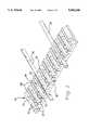
- FIG. 1is an isometric view of a splice tray having cable strain relief members of the present invention at ends thereof and a splice holder centrally disposed therebetween;
- FIG. 2is an isometric view of the splice holder of FIG. 1, with a representative single-fiber jacketed cable and a representative ribbon cable held therein;
- FIGS. 3 and 4are plan and elevation views of the splice holder
- FIG. 5is an enlarged cross-section view of FIG. 3 taken along lines 5--5 thereof and showing a ribbon-receiving slot and a cable-receiving channel at a cable tie aperture;
- FIG. 6is an enlarged view of an end portion of FIG. 4.
- a splice tray or organizer 10includes a tray body 12 having a bottom wall 14, opposed ends 16,18 and opposed side walls 20,22, as well as a preferably an optionally transparent cover member (not shown) that is securable to tray body 12.
- a splice holder 24is affixed to bottom wall 14 centrally positioned between ends 16,18 within which splice connections of pairs of associated optical fibers of single-fiber cables, or splice connections of arrays of fibers of associated ribbon cables may be positioned.
- Each splice holdermay be as disclosed in U.S. patent application Ser. No. 08/453,739 filed May 30, 1995 (concurrently herewith), or as disclosed in U.S. patent application Ser. No.
- Tray 10provides substantial fiber-holding space between the ends for generous loops of discrete fibers after being broken out from jacketed cables and ribbon cable to be disposed therein that are preferably covered by the protective lid or cover member placed thereover and affixed to tray body 12.
- Cable strain relief holders 30are affixed to tray body 12 at respective ends 16,18, such as by use of adhesive or optionally by fasteners.
- Strain relief holder 30includes a plurality of generally parallel elongate channels 32 formed into and along top surface 34 extending between first and second ends 36,38, with elongate protrusions 40 positioned between adjacent channels 32.
- Channels 32are dimensioned to receive thereinto, if desired, jacketed portions of fiber optic cables 26 (as shown in FIG. 2) that have for example diameters of 3 mm, and each is undercut to form retention ledges 42 near top surface 34 defining therebetween a constriction less wide than the cable that will hold a jacketed cable 26 in position once inserted.
- Each protrusion 40preferably has a narrow slot 44 formed thereinto from top surface 34, with narrow slot 44 being dimensioned to approximately equal the thickness of a ribbon cable to receive a ribbon cable 28 thereinto.
- Narrow slot 44is also of appropriate width to receive thereinto a buffered portion of a single fiber after being broken out from the jacket of a cable 26, if desired.
- the entrance to each slot 44includes chamfers 46 defining a lead-in facilitating insertion of a ribbon cable thereinto. Slots 44 also can assist in insertion of jacketed cables 26 into channels 32 by allowing upper portions of protrusions 40 to be flexed outwardly when a cable 26 is urged into the slightly narrower entrance to a channel 32 above retention ledges 42.
- Strain relief holder 30may also be provided with cable tie apertures 50,52 that are formed to be aligned with corresponding apertures (not shown) in the bottom wall 14 of splice tray 10, permitting mounting of conventional cable ties to the splice tray to supplement the strain relief characteristics of the strain relief holder, if desired.
- Cable tie apertures 50are shown intersecting each channel 32 and are to be used when holder 30 is to be used with ribbon cable that utilizes slots 44, while cable tie apertures 52 are shown intersecting slots 44 that are to be used when holder 30 is to be used with jacketed single fiber cable.
- strain relief holders 30may be utilized within the splice tray if desired, positioned on both sides of a splice coupler site to hold adjacent portions of buffered fiber or ribbon cable. Similarly, strain relief holders may be utilized independently of a splice tray per se, for similar purposes, with the bottom surface of the bottom member affixed to a surface such as by adhesive, double sided tape and peelable transfer paper, or other fasteners. Strain relief holder 30 may be made for example of a resilient material such as an elastomeric material like, for example, SARLINK polypropylene based elastomer, Part No.
- holder 30generally has continuous cross-sections therealong, with cable tie apertures 50,52 being formable by simple secondary operations.
- the strain relief member of the present inventionmay be utilized in pairs, one adjacent each side of the splice couplings near the center of a splice tray if desired.
- the present inventionmay also be used independently of a splice tray if desired by simply being secured to a selected surface in a desired orientation to receive and hold fiber optic members such as jacketed fiber optic cable, discrete buffered optical fiber or ribbon cable. Variations and modifications may occur to others that are within the spirit of the invention and the scope of the claims.
Landscapes
- Physics & Mathematics (AREA)
- General Physics & Mathematics (AREA)
- Optics & Photonics (AREA)
- Light Guides In General And Applications Therefor (AREA)
Abstract
Description
The present invention relates to the field of optical fiber interconnection and more particularly to strain relief members for optical fiber cable.
In multiple fiber interconnection arrangements, a plurality of pairs of associated optical fibers are to be interconnected and such interconnections must thereafter be held securely and carefully, usually in an organizer tray or cassette within a larger enclosure or cabinet, and usually in an array of such trays or cassettes. Such trays must also hold generous portions of the fibers adjacent the interconnections, or splices, to permit splice repair without requiring cable replacement. Preferably the trays or cassettes also provide for securing jacketed portions of the cables containing one or more of the optical fibers, at ends of the trays. The splice connections comprise fusion of the ends or end lengths of the associated optical fibers, or adhesive bonding, or precision clamping, and the thus-fused fiber ends are preferably maintained within a protective sleeve or adapter to maintain the precision alignment of the fibers and provide a level of physical protection and strain relief to the coupling.
One conventional method for securing optical fiber cables at ends of organizer trays has been to utilize cable ties that extend through holes in the bottom wall of a tray at each end and are snapped overtop of respective jacketed cable portions, or to utilize cable clamps in similar fashion. Within the tray the optical fibers are broken out from the jacket for ends of the optical fibers to be spliced or coupled, with such splice connections to be maintained within grooved holders centrally located between the tray ends or cable exits. Examples of splice trays or organizers or cassettes are disclosed in U.S. Pat. Nos. 4,627,686; 4,687,289; 4,702,551; 4,840,449; 5,069,523; and 5,222,184.
It is desired to provide a strain relief member at cable exits from a tray or organizer or cassette, that provides sufficient clamping of jacketed portions of fiber optic cables to relieve strain on the splice connection or coupling, without compressing or otherwise deforming the optical fiber therewithin.
It is also desired to provide a strain relief member for clamping of multifiber fiber optic ribbon cable to define strain relief therefor.
The present invention comprises a member of resilient material when strain relief of either a jacketed fiber optic cable or ribbon cable is desired. The strain relief member is placeable at either end of an organizer or tray or at the cable exit of a cassette and may be affixed to the bottom tray wall such as by adhesive or double sided tape. The strain relief member includes an array of generally parallel channels or grooves formed into and along the top surface, separated by elongate protrusions, and having constrictions along the entrances thereinto. Slots of only incremental width extend from the top surface into and along each protrusion at its center and into which may be placed ribbon cable and that are slightly compressed thereby after insertion. The channels are dimensioned to receive relatively large diameter (e.g., 3 mm) jacketed cable, with the constrictions being less wide than such cable to retain the cable in the channels after placement; the slots provide for temporary widening of the constrictions during placement of the jacketed cables into the channels.
It is an objective of the invention to provide a strain relief member that engages the fiber optic members without deforming them but establishes sufficient clamping to hold them in position and generate strain relief to protect the splice couplings thereof.
It is another objective to provide a strain relief member that provides such nondeforming strain relief clamping of fiber optic ribbon cable.
It is further an objective to provide a strain relief member that is adapted to receive either conventional fiber optic cable or ribbon cable as desired.
It is still further an objective to provide a strain relief member that facilitates quick and simple initial placement of fiber optic cable or ribbon cable thereinto.
It is yet another objective to provide such a strain relief member that easily enables removal and replacement of previously held fiber optic cable or ribbon cable.
An additional advantage of the strain relief member of the present invention is that the members may be extruded.
An embodiment of the present invention will now be described by way of example with reference to the accompanying drawings.
FIG. 1 is an isometric view of a splice tray having cable strain relief members of the present invention at ends thereof and a splice holder centrally disposed therebetween;
FIG. 2 is an isometric view of the splice holder of FIG. 1, with a representative single-fiber jacketed cable and a representative ribbon cable held therein;
FIGS. 3 and 4 are plan and elevation views of the splice holder;
FIG. 5 is an enlarged cross-section view of FIG. 3 taken alonglines 5--5 thereof and showing a ribbon-receiving slot and a cable-receiving channel at a cable tie aperture; and
FIG. 6 is an enlarged view of an end portion of FIG. 4.
A splice tray ororganizer 10 includes atray body 12 having abottom wall 14, opposedends side walls 20,22, as well as a preferably an optionally transparent cover member (not shown) that is securable to traybody 12. Asplice holder 24 is affixed tobottom wall 14 centrally positioned betweenends body 12.
Cablestrain relief holders 30 are affixed to traybody 12 atrespective ends Strain relief holder 30 includes a plurality of generally parallelelongate channels 32 formed into and alongtop surface 34 extending between first andsecond ends elongate protrusions 40 positioned betweenadjacent channels 32.Channels 32 are dimensioned to receive thereinto, if desired, jacketed portions of fiber optic cables 26 (as shown in FIG. 2) that have for example diameters of 3 mm, and each is undercut to form retention ledges 42 neartop surface 34 defining therebetween a constriction less wide than the cable that will hold a jacketedcable 26 in position once inserted.
Eachprotrusion 40 preferably has anarrow slot 44 formed thereinto fromtop surface 34, withnarrow slot 44 being dimensioned to approximately equal the thickness of a ribbon cable to receive aribbon cable 28 thereinto.Narrow slot 44 is also of appropriate width to receive thereinto a buffered portion of a single fiber after being broken out from the jacket of acable 26, if desired. Preferably the entrance to eachslot 44 includeschamfers 46 defining a lead-in facilitating insertion of a ribbon cable thereinto.Slots 44 also can assist in insertion of jacketedcables 26 intochannels 32 by allowing upper portions ofprotrusions 40 to be flexed outwardly when acable 26 is urged into the slightly narrower entrance to achannel 32 above retention ledges 42.
It can be seen thatstrain relief holders 30 may be utilized within the splice tray if desired, positioned on both sides of a splice coupler site to hold adjacent portions of buffered fiber or ribbon cable. Similarly, strain relief holders may be utilized independently of a splice tray per se, for similar purposes, with the bottom surface of the bottom member affixed to a surface such as by adhesive, double sided tape and peelable transfer paper, or other fasteners.Strain relief holder 30 may be made for example of a resilient material such as an elastomeric material like, for example, SARLINK polypropylene based elastomer, Part No. 3170 or 3160 or 9760 sold by DSM Thermoplastic Elastomers Inc., Leominster, Mass., and may be extruded rather than individually molded sinceholder 30 generally has continuous cross-sections therealong, withcable tie apertures
The strain relief member of the present invention may be utilized in pairs, one adjacent each side of the splice couplings near the center of a splice tray if desired. The present invention may also be used independently of a splice tray if desired by simply being secured to a selected surface in a desired orientation to receive and hold fiber optic members such as jacketed fiber optic cable, discrete buffered optical fiber or ribbon cable. Variations and modifications may occur to others that are within the spirit of the invention and the scope of the claims.
Claims (8)
1. A holder for fiber optic members, comprising:
a member of resilient material including an array of channels defined into a top surface thereof extending in parallel between opposed first and second ends, each said channel having a width complementary to a diameter of a jacketed fiber optic cable to receive a length of jacketed cable therealong, and each said channel having an entrance along said top surface and a constriction at said entrance less wide than a diameter of a jacketed fiber optic cable; and
said channels being separated by protrusions therebetween, and each said protrusion including a narrow width slot extending thereinto from said top surface with said slot being complementary to a thickness of a fiber optic ribbon cable and a depth sufficient to receive a ribbon cable thereinto and therealong,
whereby said channels provide holding sites for jacketed fiber optic cable and said slots provide holding sites for ribbon cable.
2. A holder as set forth in claim 1 wherein said slots include chamfered entrances defining lead-ins facilitating ribbon cable insertion.
3. A holder as set forth in claim 1 wherein said resilient material is elastomeric material.
4. A holder as set forth in claim 3 wherein said elastomeric material is a polypropylene based elastomer.
5. A fiber optic splice tray, comprising:
a tray member having a bottom wall, opposed side walls and opposed ends; and
a holder affixed to said bottom wall at each of said opposed ends, each said holder comprising a member of resilient material including an array of channels defined into a top surface thereof extending in parallel between opposed first and second ends, each said channel having a width complementary to a diameter of a jacketed fiber optic cable to receive a length of jacketed cable therealong, and each said channel having an entrance along said top surface and a constriction at said entrance less wide than a diameter of a jacketed fiber optic cable; and
said channels being separated by protrusions therebetween, and each said protrusion including a narrow width slot extending thereinto from said top surface with said slot being complementary to a thickness of a fiber optic ribbon cable and a depth sufficient to receive a ribbon cable thereinto and therealong,
whereby said channels provide holding sites for jacketed fiber optic cable and said slots provide holding sites for ribbon cable.
6. A fiber optic splice tray as set forth in claim 5 wherein said slots include chamfered entrances defining lead-ins facilitating ribbon cable insertion.
7. A fiber optic splice tray as set forth in claim 5 wherein said resilient material is elastomeric material.
8. A fiber optic splice tray as set forth in claim 7 wherein said elastomeric material is a polypropylene based elastomer.
Priority Applications (5)
| Application Number | Priority Date | Filing Date | Title |
|---|---|---|---|
| US08/453,157US5566268A (en) | 1995-05-30 | 1995-05-30 | Strain relieving holder for optical fiber cable |
| CN96194245ACN1185839A (en) | 1995-05-30 | 1996-05-15 | Optical fiber splice holder and strain relief |
| JP8536518AJPH11506219A (en) | 1995-05-30 | 1996-05-15 | Optical fiber splice holder and strain relief |
| EP96916485AEP0871911A1 (en) | 1995-05-30 | 1996-05-15 | Optical fiber splice holder and strain relief |
| PCT/US1996/007081WO1996038752A1 (en) | 1995-05-30 | 1996-05-15 | Optical fiber splice holder and strain relief |
Applications Claiming Priority (1)
| Application Number | Priority Date | Filing Date | Title |
|---|---|---|---|
| US08/453,157US5566268A (en) | 1995-05-30 | 1995-05-30 | Strain relieving holder for optical fiber cable |
Publications (1)
| Publication Number | Publication Date |
|---|---|
| US5566268Atrue US5566268A (en) | 1996-10-15 |
Family
ID=23799407
Family Applications (1)
| Application Number | Title | Priority Date | Filing Date |
|---|---|---|---|
| US08/453,157Expired - LifetimeUS5566268A (en) | 1995-05-30 | 1995-05-30 | Strain relieving holder for optical fiber cable |
Country Status (1)
| Country | Link |
|---|---|
| US (1) | US5566268A (en) |
Cited By (32)
| Publication number | Priority date | Publication date | Assignee | Title |
|---|---|---|---|---|
| US5870519A (en)* | 1994-09-28 | 1999-02-09 | Telephone Cables Limited | Slice tray with an adaptor having windows |
| US6049040A (en)* | 1997-09-17 | 2000-04-11 | Biles; Scott Douglas | Universal cable guide |
| US6195496B1 (en)* | 1999-07-30 | 2001-02-27 | Lucent Technologies, Inc. | Splice holder with tilted mounting feature |
| US6226439B1 (en)* | 1999-07-30 | 2001-05-01 | Lucent Technologies, Inc. | Splice holder with self locking feature |
| US6240236B1 (en)* | 1999-07-30 | 2001-05-29 | Lucent Technologies, Inc. | High density splice holder |
| US6249636B1 (en)* | 1999-09-07 | 2001-06-19 | Lucent Technologies, Inc. | High density fusion splice holder |
| US6285815B1 (en)* | 1999-09-07 | 2001-09-04 | Lucent Technologies Inc. | High density fusion splice holder |
| US6388824B1 (en)* | 2000-04-19 | 2002-05-14 | Corning Incorporated | Methods for holding components in an optical assembly |
| US6512179B1 (en)* | 2001-09-28 | 2003-01-28 | International Business Machines Corporation | Transmission cable strain relief device |
| US6580867B2 (en)* | 2000-07-13 | 2003-06-17 | Alcatel | Support for small-diameter filamentary elements and a bundle of filamentary elements held together by the support |
| US6636680B2 (en)* | 2001-11-07 | 2003-10-21 | Hon Hai Precision Ind. Co., Ltd. | Optical fiber cable holder |
| US20030228122A1 (en)* | 2002-06-10 | 2003-12-11 | Frank Loh | Device holder accommodating wavelength division multiplexers |
| US20040071431A1 (en)* | 2001-03-12 | 2004-04-15 | Denis Trouchet | Guide for passing optical fibers and receiving housing for optical components fitted with one such guide |
| US6801704B1 (en)* | 2003-05-30 | 2004-10-05 | Lucent Technologies Inc. | Fiber optics splice holder |
| US7345241B2 (en) | 2005-01-18 | 2008-03-18 | Panduit Corp. | Cable management support bar with strain relief clamps |
| US20080131068A1 (en)* | 2004-03-08 | 2008-06-05 | Adc Telecommunications, Inc. | Fiber Access Terminal |
| US7512304B2 (en) | 2007-03-23 | 2009-03-31 | Adc Telecommunications, Inc. | Drop terminal with anchor block for retaining a stub cable |
| US7558458B2 (en) | 2007-03-08 | 2009-07-07 | Adc Telecommunications, Inc. | Universal bracket for mounting a drop terminal |
| US7627222B2 (en) | 2004-11-03 | 2009-12-01 | Adc Telecommunications, Inc. | Fiber drop terminal |
| US7844158B2 (en) | 2007-10-09 | 2010-11-30 | Adc Telecommunications, Inc. | Mini drop terminal |
| US7903923B2 (en) | 2007-10-09 | 2011-03-08 | Adc Telecommunications, Inc. | Drop terminal releasable engagement mechanism |
| US20130028568A1 (en)* | 2011-07-29 | 2013-01-31 | Hubert Blair Beamon | Fiber optic cables seal and/or strain relief members, and related assemblies and methods |
| US20130289580A1 (en)* | 2012-04-26 | 2013-10-31 | Bio-Medical Engineering (HK) Limited | Magnetic-anchored robotic system |
| US8622481B2 (en) | 2011-01-25 | 2014-01-07 | Joy Mm Delaware, Inc. | Fiber optic cable protection in a mining system |
| US9052468B2 (en) | 2011-03-04 | 2015-06-09 | Corning Cable Systems Llc | Fiber optic adapter mount |
| US9110267B2 (en) | 2012-10-26 | 2015-08-18 | Ccs Technology, Inc. | Strain relief device for cables and fiber optic distribution device |
| US20150323746A1 (en)* | 2012-02-10 | 2015-11-12 | Qingyun Yuan | A multi-function cutting fixture |
| US20160093987A1 (en)* | 2014-09-25 | 2016-03-31 | Foxconn Interconnect Technology Limited | Cable connector assembly having improved wire spacer |
| US9488793B2 (en) | 2013-09-10 | 2016-11-08 | Corning Optical Communications LLC | Combined optical fiber and power cable |
| US20180259738A1 (en)* | 2012-10-31 | 2018-09-13 | Commscope Technologies Llc | Anchoring cables to rack with cable clamp arrangements |
| US10179033B2 (en) | 2012-04-26 | 2019-01-15 | Bio-Medical Engineering (HK) Limited | Magnetic-anchored robotic system |
| US11370588B2 (en)* | 2019-02-01 | 2022-06-28 | Ortronics, Inc. | Packaging assemblies for optical fiber applications |
Citations (18)
| Publication number | Priority date | Publication date | Assignee | Title |
|---|---|---|---|---|
| US3768146A (en)* | 1972-02-22 | 1973-10-30 | Bell Telephone Labor Inc | Method of splicing optical fibers |
| US4627686A (en)* | 1984-08-10 | 1986-12-09 | Siecor Corporation | Splicing tray for optical fibers |
| US4687289A (en)* | 1985-09-17 | 1987-08-18 | Brintec Corporation | Fiberoptic splice organizer |
| US4702551A (en)* | 1984-10-11 | 1987-10-27 | Reliance Comm/Tec Corporation | Method and apparatus for handling and storing cabled spliced ends of fiber optics |
| US4793681A (en)* | 1988-04-18 | 1988-12-27 | Gte Products Corporation | Splice cradle |
| US4840449A (en)* | 1988-01-27 | 1989-06-20 | American Telephone And Telegraph Company, At&T Bell Laboratories | Optical fiber splice organizer |
| US4842362A (en)* | 1982-09-14 | 1989-06-27 | Gte Products Corporation | Housing for a fiber optic splice |
| US4854661A (en)* | 1987-11-05 | 1989-08-08 | Gte Products Corporation | Splice cradle |
| US4911521A (en)* | 1988-03-15 | 1990-03-27 | Sumitomo Electric Industries, Ltd. | Connecting box for multi-optical fiber cable |
| US5046811A (en)* | 1989-07-17 | 1991-09-10 | Jung Roger E | Junction box for optical communications cords, and gland assembly for cord |
| US5069523A (en)* | 1988-12-08 | 1991-12-03 | Siemens Aktiengesellschaft | Cassette for spare lengths of light waveguides to be used at the site to be spliced |
| US5071211A (en)* | 1988-12-20 | 1991-12-10 | Northern Telecom Limited | Connector holders and distribution frame and connector holder assemblies for optical cable |
| US5208893A (en)* | 1992-05-21 | 1993-05-04 | Raynet Corporation | Optical fiber splice tray and splice holder |
| US5222184A (en)* | 1989-10-10 | 1993-06-22 | Bowthorpe-Hellermann Limited | Optical fibre splice storage tray |
| US5278933A (en)* | 1992-06-30 | 1994-01-11 | Hunsinger Terrance D | Fiber optic splice organizer and associated method |
| US5375185A (en)* | 1993-04-30 | 1994-12-20 | Keptel, Inc. | Apparatus for storing and organizing spliced optical fibers |
| US5416882A (en)* | 1992-11-25 | 1995-05-16 | Mars Actel | Device for positioning and retaining optical fibers in a layer |
| US5420956A (en)* | 1993-01-28 | 1995-05-30 | Krone Aktiengesellschaft | Case for passive optical components |
- 1995
- 1995-05-30USUS08/453,157patent/US5566268A/ennot_activeExpired - Lifetime
Patent Citations (18)
| Publication number | Priority date | Publication date | Assignee | Title |
|---|---|---|---|---|
| US3768146A (en)* | 1972-02-22 | 1973-10-30 | Bell Telephone Labor Inc | Method of splicing optical fibers |
| US4842362A (en)* | 1982-09-14 | 1989-06-27 | Gte Products Corporation | Housing for a fiber optic splice |
| US4627686A (en)* | 1984-08-10 | 1986-12-09 | Siecor Corporation | Splicing tray for optical fibers |
| US4702551A (en)* | 1984-10-11 | 1987-10-27 | Reliance Comm/Tec Corporation | Method and apparatus for handling and storing cabled spliced ends of fiber optics |
| US4687289A (en)* | 1985-09-17 | 1987-08-18 | Brintec Corporation | Fiberoptic splice organizer |
| US4854661A (en)* | 1987-11-05 | 1989-08-08 | Gte Products Corporation | Splice cradle |
| US4840449A (en)* | 1988-01-27 | 1989-06-20 | American Telephone And Telegraph Company, At&T Bell Laboratories | Optical fiber splice organizer |
| US4911521A (en)* | 1988-03-15 | 1990-03-27 | Sumitomo Electric Industries, Ltd. | Connecting box for multi-optical fiber cable |
| US4793681A (en)* | 1988-04-18 | 1988-12-27 | Gte Products Corporation | Splice cradle |
| US5069523A (en)* | 1988-12-08 | 1991-12-03 | Siemens Aktiengesellschaft | Cassette for spare lengths of light waveguides to be used at the site to be spliced |
| US5071211A (en)* | 1988-12-20 | 1991-12-10 | Northern Telecom Limited | Connector holders and distribution frame and connector holder assemblies for optical cable |
| US5046811A (en)* | 1989-07-17 | 1991-09-10 | Jung Roger E | Junction box for optical communications cords, and gland assembly for cord |
| US5222184A (en)* | 1989-10-10 | 1993-06-22 | Bowthorpe-Hellermann Limited | Optical fibre splice storage tray |
| US5208893A (en)* | 1992-05-21 | 1993-05-04 | Raynet Corporation | Optical fiber splice tray and splice holder |
| US5278933A (en)* | 1992-06-30 | 1994-01-11 | Hunsinger Terrance D | Fiber optic splice organizer and associated method |
| US5416882A (en)* | 1992-11-25 | 1995-05-16 | Mars Actel | Device for positioning and retaining optical fibers in a layer |
| US5420956A (en)* | 1993-01-28 | 1995-05-30 | Krone Aktiengesellschaft | Case for passive optical components |
| US5375185A (en)* | 1993-04-30 | 1994-12-20 | Keptel, Inc. | Apparatus for storing and organizing spliced optical fibers |
Non-Patent Citations (8)
| Title |
|---|
| AMP Catalog 82188 , AMP Fiber Optic Products , p. 147; Feb., 1993; AMP Incorporated, Harrisburg, PA.* |
| AMP Catalog 82188, "AMP Fiber Optic Products", p. 147; Feb., 1993; AMP Incorporated, Harrisburg, PA. |
| AMP Instruction Sheet 408 9490 , AMP Organizer Holder Kits and Trays , five pp.; Mar. 1993; AMP Incorporated, Harrisburg, PA.* |
| AMP Instruction Sheet 408-9490, "AMP Organizer Holder Kits and Trays", five pp.; Mar. 1993; AMP Incorporated, Harrisburg, PA. |
| Bejed Drawing , BJ 1742C 005 12 Fiber Universal Splice Unit , Feb., 1994; BEJED Communication Products, Portland, OR.* |
| Bejed Drawing, "BJ-1742C-005 12 Fiber Universal Splice Unit", Feb., 1994; BEJED Communication Products, Portland, OR. |
| DSM Brochure , Sarlink 3000 Thermoplastic Elastomers , three pp. Nov., 1994; DSM Thermoplastic Elastomers, Inc., Leominster, MA.* |
| DSM Brochure, "Sarlink 3000 Thermoplastic Elastomers", three pp. Nov., 1994; DSM Thermoplastic Elastomers, Inc., Leominster, MA. |
Cited By (48)
| Publication number | Priority date | Publication date | Assignee | Title |
|---|---|---|---|---|
| US5870519A (en)* | 1994-09-28 | 1999-02-09 | Telephone Cables Limited | Slice tray with an adaptor having windows |
| US6049040A (en)* | 1997-09-17 | 2000-04-11 | Biles; Scott Douglas | Universal cable guide |
| US6195496B1 (en)* | 1999-07-30 | 2001-02-27 | Lucent Technologies, Inc. | Splice holder with tilted mounting feature |
| US6226439B1 (en)* | 1999-07-30 | 2001-05-01 | Lucent Technologies, Inc. | Splice holder with self locking feature |
| US6240236B1 (en)* | 1999-07-30 | 2001-05-29 | Lucent Technologies, Inc. | High density splice holder |
| US6249636B1 (en)* | 1999-09-07 | 2001-06-19 | Lucent Technologies, Inc. | High density fusion splice holder |
| US6285815B1 (en)* | 1999-09-07 | 2001-09-04 | Lucent Technologies Inc. | High density fusion splice holder |
| US6388824B1 (en)* | 2000-04-19 | 2002-05-14 | Corning Incorporated | Methods for holding components in an optical assembly |
| US6580867B2 (en)* | 2000-07-13 | 2003-06-17 | Alcatel | Support for small-diameter filamentary elements and a bundle of filamentary elements held together by the support |
| US20040071431A1 (en)* | 2001-03-12 | 2004-04-15 | Denis Trouchet | Guide for passing optical fibers and receiving housing for optical components fitted with one such guide |
| US6512179B1 (en)* | 2001-09-28 | 2003-01-28 | International Business Machines Corporation | Transmission cable strain relief device |
| US6636680B2 (en)* | 2001-11-07 | 2003-10-21 | Hon Hai Precision Ind. Co., Ltd. | Optical fiber cable holder |
| US20030228122A1 (en)* | 2002-06-10 | 2003-12-11 | Frank Loh | Device holder accommodating wavelength division multiplexers |
| US6775457B2 (en)* | 2002-06-10 | 2004-08-10 | Hon Hai Precison Ind. Co., Ltd. | Device holder accommodating wavelength division multiplexers |
| US6801704B1 (en)* | 2003-05-30 | 2004-10-05 | Lucent Technologies Inc. | Fiber optics splice holder |
| US8363999B2 (en) | 2004-03-08 | 2013-01-29 | Adc Telecommunications, Inc. | Fiber access terminal |
| US7941027B2 (en) | 2004-03-08 | 2011-05-10 | Adc Telecommunications, Inc. | Fiber access terminal |
| US20080131068A1 (en)* | 2004-03-08 | 2008-06-05 | Adc Telecommunications, Inc. | Fiber Access Terminal |
| US7480437B2 (en) | 2004-03-08 | 2009-01-20 | Adc Telecommunications, Inc. | Fiber access terminal |
| US7539388B2 (en) | 2004-03-08 | 2009-05-26 | Adc Telecommunications, Inc. | Fiber access terminal |
| US7539387B2 (en) | 2004-03-08 | 2009-05-26 | Adc Telecommunications, Inc. | Fiber access terminal |
| US7627222B2 (en) | 2004-11-03 | 2009-12-01 | Adc Telecommunications, Inc. | Fiber drop terminal |
| US20080108231A1 (en)* | 2005-01-18 | 2008-05-08 | Panduit Corp. | Cable Management Support Bar with Strain Relief Clamps |
| US7619164B2 (en) | 2005-01-18 | 2009-11-17 | Panduit Corp. | Cable management support bar with strain relief clamps |
| US7345241B2 (en) | 2005-01-18 | 2008-03-18 | Panduit Corp. | Cable management support bar with strain relief clamps |
| US7558458B2 (en) | 2007-03-08 | 2009-07-07 | Adc Telecommunications, Inc. | Universal bracket for mounting a drop terminal |
| US7512304B2 (en) | 2007-03-23 | 2009-03-31 | Adc Telecommunications, Inc. | Drop terminal with anchor block for retaining a stub cable |
| US7903923B2 (en) | 2007-10-09 | 2011-03-08 | Adc Telecommunications, Inc. | Drop terminal releasable engagement mechanism |
| US8213761B2 (en) | 2007-10-09 | 2012-07-03 | Adc Telecommunications | Mini drop terminal |
| US7844158B2 (en) | 2007-10-09 | 2010-11-30 | Adc Telecommunications, Inc. | Mini drop terminal |
| US8622481B2 (en) | 2011-01-25 | 2014-01-07 | Joy Mm Delaware, Inc. | Fiber optic cable protection in a mining system |
| US8950822B2 (en) | 2011-01-25 | 2015-02-10 | Joy Mm Delaware, Inc. | Fiber optic cable protection in a mining system |
| US9052468B2 (en) | 2011-03-04 | 2015-06-09 | Corning Cable Systems Llc | Fiber optic adapter mount |
| US20130028568A1 (en)* | 2011-07-29 | 2013-01-31 | Hubert Blair Beamon | Fiber optic cables seal and/or strain relief members, and related assemblies and methods |
| CN103733104A (en)* | 2011-07-29 | 2014-04-16 | 康宁光缆系统有限责任公司 | Fiber optic cable seal and/or strain relief members |
| US9110266B2 (en)* | 2011-07-29 | 2015-08-18 | Corning Cable Systems Llc | Fiber optic cables seal and/or strain relief members, and related assemblies and methods |
| CN103733104B (en)* | 2011-07-29 | 2017-05-24 | 康宁光电通信有限责任公司 | Fiber optic cable seal and/or strain relief members |
| US20150323746A1 (en)* | 2012-02-10 | 2015-11-12 | Qingyun Yuan | A multi-function cutting fixture |
| US9726828B2 (en)* | 2012-02-10 | 2017-08-08 | Inno Instrument (China) Inc. | Multi-function cutting fixture |
| US8891924B2 (en)* | 2012-04-26 | 2014-11-18 | Bio-Medical Engineering (HK) Limited | Magnetic-anchored robotic system |
| US20130289580A1 (en)* | 2012-04-26 | 2013-10-31 | Bio-Medical Engineering (HK) Limited | Magnetic-anchored robotic system |
| US10179033B2 (en) | 2012-04-26 | 2019-01-15 | Bio-Medical Engineering (HK) Limited | Magnetic-anchored robotic system |
| US9110267B2 (en) | 2012-10-26 | 2015-08-18 | Ccs Technology, Inc. | Strain relief device for cables and fiber optic distribution device |
| US20180259738A1 (en)* | 2012-10-31 | 2018-09-13 | Commscope Technologies Llc | Anchoring cables to rack with cable clamp arrangements |
| US9488793B2 (en) | 2013-09-10 | 2016-11-08 | Corning Optical Communications LLC | Combined optical fiber and power cable |
| US20160093987A1 (en)* | 2014-09-25 | 2016-03-31 | Foxconn Interconnect Technology Limited | Cable connector assembly having improved wire spacer |
| US9843143B2 (en)* | 2014-09-25 | 2017-12-12 | Foxconn Interconnect Technology Limited | Cable connector assembly having improved wire spacer |
| US11370588B2 (en)* | 2019-02-01 | 2022-06-28 | Ortronics, Inc. | Packaging assemblies for optical fiber applications |
Similar Documents
| Publication | Publication Date | Title |
|---|---|---|
| US5566268A (en) | Strain relieving holder for optical fiber cable | |
| US5530786A (en) | Holding for optical fiber splice couplings | |
| US5566269A (en) | Strain relieving holder for optical fiber cable | |
| WO1996038752A1 (en) | Optical fiber splice holder and strain relief | |
| EP0490644B1 (en) | Optical fiber cable closure having enhanced storage capability | |
| US10345539B2 (en) | Telecommunications cabinet with connector storage | |
| US5278933A (en) | Fiber optic splice organizer and associated method | |
| US4627686A (en) | Splicing tray for optical fibers | |
| US5450518A (en) | Optical fiber cable splice closure | |
| CA2041299C (en) | Splice tray and method | |
| US5450517A (en) | Re-enterable fiber optic splicer for data communications | |
| US6078718A (en) | Strain relief device for plurality of optical ribbon fibers | |
| AU722094B2 (en) | Optical fibre organizer | |
| US4784456A (en) | Fiber optic connector | |
| EP0178179A3 (en) | Handling and storing cable spliced ends of optical fibers | |
| WO2007139823A2 (en) | Multi-directional optical splice organizer | |
| EP0646811A2 (en) | Breakout for optical fibres | |
| US5127070A (en) | Optical fiber distribution module | |
| KR20010113965A (en) | Break-out device | |
| JP3345345B2 (en) | Optical fiber connection section fixing base | |
| AU2013267049B2 (en) | Multi-position fiber optic connector holder and method | |
| GB2283373A (en) | Breakout | |
| AU2016201870B2 (en) | Multi-position fiber optic connector holder and method | |
| WO1992015911A1 (en) | Fibre separator |
Legal Events
| Date | Code | Title | Description |
|---|---|---|---|
| AS | Assignment | Owner name:WHITAKER CORPORATION, THE, DELAWARE Free format text:ASSIGNMENT OF ASSIGNORS INTEREST;ASSIGNORS:RADLIFF, DAVID RAY;KEENER, SCOTT ALAN;REEL/FRAME:007569/0047 Effective date:19950711 | |
| STCF | Information on status: patent grant | Free format text:PATENTED CASE | |
| FPAY | Fee payment | Year of fee payment:4 | |
| FPAY | Fee payment | Year of fee payment:8 | |
| FPAY | Fee payment | Year of fee payment:12 | |
| REMI | Maintenance fee reminder mailed | ||
| AS | Assignment | Owner name:THE WHITAKER LLC, DELAWARE Free format text:CERTIFICATE OF CONVERSION;ASSIGNOR:THE WHITAKER CORPORATION;REEL/FRAME:036068/0954 Effective date:20100805 | |
| AS | Assignment | Owner name:COMMSCOPE EMEA LIMITED, IRELAND Free format text:ASSIGNMENT OF ASSIGNORS INTEREST;ASSIGNOR:THE WHITAKER LLC;REEL/FRAME:036942/0001 Effective date:20150824 |