US5566249A - Apparatus for detecting bubbles in coverslip adhesive - Google Patents
Apparatus for detecting bubbles in coverslip adhesiveDownload PDFInfo
- Publication number
- US5566249A US5566249AUS08/309,077US30907794AUS5566249AUS 5566249 AUS5566249 AUS 5566249AUS 30907794 AUS30907794 AUS 30907794AUS 5566249 AUS5566249 AUS 5566249A
- Authority
- US
- United States
- Prior art keywords
- bubble
- map
- image
- slide
- gray scale
- Prior art date
- Legal status (The legal status is an assumption and is not a legal conclusion. Google has not performed a legal analysis and makes no representation as to the accuracy of the status listed.)
- Expired - Lifetime
Links
Images


Classifications
- G—PHYSICS
- G06—COMPUTING OR CALCULATING; COUNTING
- G06V—IMAGE OR VIDEO RECOGNITION OR UNDERSTANDING
- G06V20/00—Scenes; Scene-specific elements
- G06V20/60—Type of objects
- G06V20/69—Microscopic objects, e.g. biological cells or cellular parts
Definitions
- the inventionrelates to an automated microscope cytological classifier and, more particularly, to an automated cytological classifier that includes an apparatus for detecting bubbles in coverslip adhesive.
- edges of the bubblesare themselves resolved as heavy dark objects which are not of interest to the system analyzing the specimen. Therefore, it is undesirable to spend time trying to focus and analyze the bubble edges at high magnification.
- the prior arthas detected bubbles within liquids flowing through tubes, in essence, a one dimensional problem.
- the common techniqueis to use a photosensor of some type which detects the boundary between the liquid and the bubble.
- a typical microscope slide 10is shown exhibiting voids or bubbles in the coverslip adhesive.
- the microscope slide 10comprises a plate 12 including an identification area 11.
- a coverslip 14is placed over a specimen using an adhesive.
- the placement of the coverslip 14sometimes unfortunately results in bubbles forming in the adhesive.
- bubblesare shown as circular bubble 15, irregular bubble 17 and edge bubble 16. Since the perimeters of such bubbles usually exceed the field of view of microscopes used to view such slides, the size or existence of such bubbles often goes undetected.
- the inventionprovides an apparatus and method for detecting bubbles in coverslip adhesive. Bubbles in coverslip adhesive may span large areas of the coverslip.
- the apparatus of the inventionstarts by acquiring 4 x gray scale images of the coverslip. Each image is approximately 1.408 mm by 1.408 mm, and the entire set of images collected tiles the region under the coverslip. Image conditioning is performed on each 4 x image. Each conditioned gray scale image is binomially filtered providing a binomial filtered image. The conditioned gray scale image is subtracted from the binomial filtered image to produce a high pass enhanced image. An object mask detection is performed on the high pass filtered image. The results of the object mask detection are passed through a classifier to identify bubble edges.
- the bubble edges from all 4 x imagesare pieced together to form a map of bubbled edges over the entire coverslip area.
- the edgesare analyzed and the bubbles in the map are separated from each other and their outlines are filled to include the interiors of each bubble.
- the resulting filled bubble areasare eliminated from further processing by the automated microscope of the automated cytological classifier of the system.
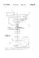
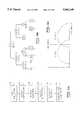
- FIGS. 1A, 1B and 1Cshow a schematic diagram of the apparatus of the invention.
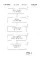
- FIG. 2shows the image segmentation process of the invention.
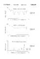
- FIGS. 3A, 3B and 3Cshow the effect of the object mask detection method of the invention when applied to one scan line of a typical image.
- FIGS. 4A, 4B and 4Cshow the air bubble edge detection method of the invention as applied to a thresholded object.
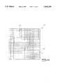
- FIG. 5Ashows the coverslip area covered by a grid of high power images.
- FIG. 5Bshows one method of the invention to find a bubble map.
- FIG. 6shows the original bubble map
- FIG. 7Ashows the dilated bubble map
- FIG. 7Bshows the dilation result
- FIG. 8Ashows the labelled bubble map
- FIG. 8Bshows the labelled bubble map with vertical fill.
- FIG. 8Cshows the labelled bubble map, horizontal fill.
- FIG. 9Ashows the filled bubble map reduced to binary.
- FIG. 9Bshows the eroded filled bubble map.
- FIG. 9Cshows the final bubble map
- FIG. 10Ashows a method of the invention used to train a classifier.
- FIG. 10Bshows one example of a decision tree classifier of the invention.
- FIG. 10Cillustrates a graphical description of the method of the invention for finding a threshold value.
- FIG. 11shows a typical slide with a coverslip having bubbles in its coverslip adhesive.
- the system disclosed hereinis used in a system for analyzing cervical pap smears, such as that shown and disclosed in U.S. patent application Ser. No. 07/838,064, entitled “Method For Identifying Normal Biomedical Specimens", by Alan C. Nelson, et al., filed Feb. 18, 1992; U.S. patent application Ser. No. 08/179,812 filed Jan. 10, 1994 which is a continuation in part of U.S. patent application Ser. No. 07/838,395, entitled “Method For Identifying Objects Using Data Processing Techniques", by S. James Lee, et al., filed Feb. 18, 1992; U.S. patent application Ser. No.
- the present inventionis also related to biological and cytological systems as described in the following patent applications which are assigned to the same assignee as the present invention, filed on Sep. 20, 1994 unless otherwise noted, and which are all hereby incorporated by reference including U.S. patent application Ser. No. 08/309,118, to Kuan et al. entitled, "Field Prioritization Apparatus and Method," U.S. patent application Ser. No. 08/309,061 to Wilhelm et al., entitled “Apparatus for Automated Identification of Cell Groupings on a Biological Specimen," U.S. patent application Ser. No. 08/309,116 to Meyer et al.
- FIGS. 1A, 1B and 1Cshow a schematic diagram of one embodiment of the apparatus of the invention for detecting bubbles in coverslip adhesive.
- the apparatus of the inventioncomprises an imaging system 502, a motion control system 504, an image processing system 536, a central processing system 540, and a workstation 542.
- the imaging system 502is comprised of an illuminator 508, imaging optics 510, a CCD camera 512, an illumination sensor 514 and an image capture and focus system 516.
- the image capture and focus system 516provides video timing data to the CCD cameras 512, the CCD cameras 512 provide images comprising scan lines to the image capture and focus system 516.
- An illumination sensor intensityis provided to the image capture and focus system 516 where an illumination sensor 514 receives the sample of the image from the optics 510.
- the opticsmay further comprise an automated microscope.
- the illuminator 508provides illumination of a slide.
- the image capture and focus system 516provides data to a VME bus 538.
- the VME busdistributes the data to an image processing system 536.
- the image processing system 536is comprised of field-of-view processors 568.
- the imagesare sent along the image bus 564 from the image capture and focus system 516.
- a central processor 540controls the operation of the invention through the VME bus 538.
- the central processor 562comprises a MOTOROLA 68030 (TM) CPU.
- the motion controller 504is comprised of a tray handler 518, a microscope stage controller 520, a microscope tray controller 522, and a calibration slide 524.
- the motor drivers 526position the slide under the optics.
- a bar code reader 528reads a barcode located on the slide 524.
- a touch sensor 530determines whether a slide is under the microscope objectives, and a door interlock 532 prevents operation in case the doors are open.
- Motion controller 534controls the motor drivers 526 in response to the central processor 540.
- An Ethernet communication system 560communicates to a workstation 542 to provide control of the system.
- a hard disk 544is controlled by workstation 550.
- workstation 550may comprise a Sun SPARC Classic (TM) workstation.
- a tape drive 546is connected to the workstation 550 as well as a modem 548, a monitor 552, a keyboard 554, and a mouse pointing device 556.
- a printer 558is connected to the ethernet 560
- the central computer 540running a real time operating system, controls the microscope and the processor to acquire and digitize images from the microscope.
- the flatness of the slidemay be checked, for example, by contacting the four corners of the slide using a computer controlled touch sensor.
- the computer 540also controls the microscope stage to position the specimen under the microscope objective, and from one to 15 field of view (FOV) processors 568 which receive images under control of the computer 540.
- FOVfield of view
- the bubble detection process of the inventionis divided into two sub-processes.
- One subprocessbubble edge detection FOV processing
- FOV processingis performed on the image processing computers 536 to analyze one image per FOV acquired from the microscope 510 and determine if bubble edges exist or not.
- the second sub-process, FOV processing result collection and analysisdirects a searching pattern, collects the individual image results from the image processing computers 536, and analyzes the collected data to determine the overall bubble regions given the detected bubble edges.
- the bubble edge detection FOV processing method of the inventionis designed to process low power, such as 4 x, microscope images and locate objects that are potential edges of air-bubbles on a cover-slipped microscope slide.
- the segmentation process and the parametersare designed based on the overall image characteristics of a training image set in order to segment out the most objects of interest.
- the edge detection methodcomprises the steps of acquiring a gray scale image 22, image conditioning 24, object mask detection 26, air bubble edge detection 28 and producing a result 30.
- image conditioning step 24gray scale 4 x images from step 22 are clipped to limit image pixel values that range between 0 and 255 to a detection range of 25 to 180 thus providing a conditioned image.
- Objects of interest, i.e. bubble edges,should be well within this range. However, pixels of slide background may go beyond this range.
- the object mask detection step 26performs high-pass filtering on the conditioned image from step 24.
- the low spatial frequency component of an imagecorresponds to the image's background, which are areas of gradual, or smooth, change in contrast.
- the high spatial frequency component of an imagecorresponds to sharp changes of pixel values of neighboring pixels. Therefore, since the objective of the segmentation process of the invention is to find pixels that represent bubble edges, a high-pass filtering technique is used. In implementation, a binomial filtering method of kernel size 5 ⁇ 5 is used. These results of one scan line of such a binomial filtered image obtained from the gray scale image 32 are illustrated in FIGS. 3A, 3B and 3C.
- FIGS. 3A, 3B, and 3Cshow a pixel intensity profile of a one-dimensional line of an image 32 represented therein in graphical form.
- the gray scale imagehas been clipped to limit the gray scale dynamic range as part of the image conditioning step 24. Since objects at 4 x magnification are small, a binomial filtering method using a 5 ⁇ 5 pixel kernel is applied. The result is the binomial filtered image 34 shown in FIG. 3B.
- the original image 32is then subtracted from the binomial filtered image 34 producing the high-passed enhanced image 36 illustrated as a plurality of peaks in FIG. 3C.
- the high-pass operationsubstantially removes any low frequency component representative of the low contrast area of an image.
- the high-passed enhanced imagemay advantageously be partitioned into a 5 ⁇ 5 array of sub-images or zones, then each zone is adaptively thresholded by its threshold value 38.
- Each adaptive threshold valueis computed based on pixel histograms from the zone. Threshold values selected by this method are based on the criteria of maximizing between-class variance.
- the two classes of pixels in an imageare the object-pixel class and the background pixel class.
- the result of the air bubble edge detection step 28is a binary image containing a mask of potential edges along with smaller high frequency clutter 45, as shown in FIG. 4A.
- FIGS. 4A, 4B and 4Cshow an illustration of air bubble edge detection.
- the bubble edge detection process of the inventionmay work at a coarse image resolution since bubble edges are usually much wider and longer than 2-3 pixels. Therefore, the thresholded image from the previous step is first down-sampled.
- a down-sampled imageis generated by selecting every other pixel both horizontally and vertically from the original resolution image, reducing the data volume to one quarter of that of the original image. This reduction increases processing speed.
- morphological operationsremove isolated single pixels since they are assumed not to be part of the bubble images.
- Two morphological opening operations using structure elements of size 1 ⁇ 2 and 2 ⁇ 1are performed individually, then a logical OR (sum) of the results from the two opening operations is generated.
- the inventiondetects foreground pixels forming objects of various shapes in the binary images using connected component analysis. Large objects, greater than 100 pixels in size for example, are detected. The shape attributes of these large objects are detected as well. Attributes of these large objects are passed through a classifier to identify those objects that meet the size and shape criteria of bubble edges 42. The classifier's size and shape parameters are derived from a set of exemplar images that contain air bubble edges.
- the classifier apparatus 500 of the inventionis trained to recognize air bubble edges using a classifier.
- the training data collectedare the images containing the objects which are potential bubble edges.
- Features of the objectare measured.
- the discrimination capabilities of the measured features from the objectsvary from very strong to very weak.
- FIG. 10Ashows the method of the invention used to train a classifier.
- First images of sample objectsare collected in step 702 from the slide.
- Featuresare computed from the objects in step 704.
- Featuresare selected among the features that were computed in step 706.
- the classifieris built in step 710. The details of the classifier construction are described below.
- the performance of the classifieris evaluated in step 712.
- FIG. 10Bshows one example of a decision tree classifier of the invention.
- a decision tree classifierall features have a statistical distribution.
- the inventiondetermines which feature has the most potential discriminating power.
- the discriminating poweris based on a cost-error function.
- the cost-error functionis designed to find a predetermined percent of true conditions as true. This predetermined percent is known as the sensitivity of the cost function.
- the cost functionmay be set equal to 0.90. This sensitivity is applied to every feature.
- the inventioncalculates an error and steps through the range of all feature values from the lowest value in the data to the highest value in the data to find a minimum cost function.
- a thresholdwas found by minimizing the total number of trues that are called false plus the total number of falses that are called trues times their respective weighting functions.
- the apparatus of the inventionchecks all ranges between the minimum and maximum feature values. It computes the error using the error functions and compares the error against stopping rules.
- a stopping ruledetermines when to stop splitting the decision tree.
- the inventiontakes training objects and computes their features.
- the statistical analysisdetermines the confidence level using the sensitivity function and a range is determined with a threshold value. This threshold value represents the minimum error for this particular feature set.
- the objectthen may be classified by determining whether the particular feature value is above, below or equal to the threshold.
- Imagesare processed to calculate features for each segmented object.
- Featuresare numeric measurements.
- the number of features computedis large, for example, the number may comprise over 140 features.
- the feature selection processthen determines a subset of features that can best discriminate different classes of objects in the training data set.
- Some typical methods used for feature selectionare the discriminant analysis method, see Pattern Classification and Scene analysis, by R. Duda & P. Hart, 1973, and Stepdisc Procedure, SAS, SAS Institute Inc.
- a classifieris built.
- the methodology usedis similar to the decision tree methodology described above. See also Classification and Regression Trees, by L. Breiman, J. Friedman, et al., Wadsworth & Brooks, 1984.
- FIG. 10Bshows one example of a decision tree classifier constructed by the repeated splitting of subsets of an input data set X into two descendant subsets, beginning with X itself. This process is shown for a hypothetical 3-class tree.
- the splitting rules at the nonterminal nodes, circles in FIG. 10B,are computed by several different methods: the single feature threshold method, or Fisher's linear feature combination thresholding method.
- the single feature thresholding methodwill select one feature among all the available features that can best separate the data set of that nonterminal node into two disjoint sets, and set the proper threshold value.
- the data samples having that feature value less than the thresholdgo to the left descending node, the data samples having that feature value greater than or equal to the threshold go to the right descending node.
- Each nonterminal nodedetermines the feature and threshold solely based on the data in that node, e.g., split2 is based on X2.
- the Fisher's linear feature combination thresholding methoddiffers from the single feature thresholding method in that all available features are used in computing the linear feature combination, i.e. the weighted sum of all features.
- the weights usedare computed based on the Fisher's linear discriminant method, see Duda & Hart, pages 114-118. Then the threshold is set on the projected linear space using the criteria of best, minimum error rate separating the data set of that nonterminal node into two disjoint sets.
- the decision to split or not to split a subset of datais based on the number of data samples or the error rate of classification. If the number of samples is small: stop splitting. Likewise if the error rate is less than a predetermined value: stop splitting. For example, data subset X6 from split3 satisfies the criteria and is classified as class1.
- the performance of the constructed decision tree classifiersare evaluated by classifying an independent testing data set and computing the resulting error rate.
- classifiers of the inventionmay include run-time speed-efficient coding the feature calculation functions that calculate only the selected features, and coding of the built classifier as a classifier function or may be embodied in application specific hardware.
- the slideis scanned with a 4 x microscope objective imaging a field of view (FOV) of 1.408 millimeters square onto a 512 ⁇ 512 pixel array.
- FOVfield of view
- the set of imagescovers the entire area under the slide coverslip.
- each imageis broken down into a 5 ⁇ 5 array of sub-images, see zone 46 as an example, which are analyzed to detect occurrences of bubble edges.
- the results of the FOV analysisare stored in a two dimensional array dimensioned such that each of the sub-images is represented by one element in the array.
- the index of the array elementscorresponds one to one to the positions of the sub-images on the slide. For example, a 25 by 50 millimeter cover slip is covered by approximately an array of 18 by 36 FOVs at 4 x magnification. Breaking the images into the sub-images yields an array size of 90 by 180 elements.
- the two dimensional arrayis indexed by an X index and a Y index. Element (0,0) refers to the minimumX and minimumY sub-image analyzed during the scan. Each increment of one of the elements indicates an increase of 1.408 / 5 or 0.282 millimeters in the corresponding direction.
- the results from a particular FOVare stored in the corresponding position in the results array 48.
- the result from each sub-imageis a binary value, 1 indicates a bubble edge exists at that position, 0 indicates no bubble edge.
- this arrayis referred to as a bubble edge map, and processed in order to connect the so far uncorrelated bubble edge positions.
- FIGS. 5B, 6, 7A, 7B, 8A, 8B, 8C, 9A, 9B and 9Cillustrate the operations performed on a portion of a typical bubble edge map which contains one complete bubble and a fragment of a second bubble.
- FIG. 5Aillustrates a coverslip area covered by a grid of high power images forming a bubble edge map 110.
- FIG. 5Billustrates a flow diagram of one example of a method of the invention to find a bubble map.
- the method to find a bubble mapcomprises starting with an original bubble edge map 110 illustrated, for example, in FIG. 6.
- Bubble edge map 110is dilated at dilation step 112 yielding a dilated bubble edge map 111.
- the processthen continues by performing connected component analysis 114, labeling the bubble edge map 115, filling in step 116, reducing the filled bubble map to binary 118, eroding the binary bubble map 120 and producing a final bubble map 122.
- FIG. 7Ashows the step of dilating 112 the bubble edge map 110 by a 3 ⁇ 3 "+" shaped structuring element.
- This dilation 112has the effect of filling gaps in a bubble edge which may have been caused by the FOV processing missing the edge in a sub-image.
- FIG. 7Bshows a result of the dilation 112.
- FIG. 8Ashows the step of performing a connected component analysis 114 with labels for each connected component. After this step, each separate object consisting of edge points adjoining other edge points is given a distinct label.
- the bubble mapis now called the labelled bubble edge map.
- FIGS. 8B and 8Cshow the steps of filling in the connected components of the labelled bubble edge map by filling any region of a row or column bounded by elements with the same label. From the completion of this step 116, the label is no longer significant and the map is once again treated as binary 9A, and called the filled bubble map.
- FIG. 8Bshows the vertical fill 16B step and
- FIG. 8Cshows the horizontal fill step 16A.
- FIG. 9Bshows the step of eroding 120 the filled bubble map 98 by a 3 ⁇ 3 "+" shaped structuring element. This erosion decreases the size of the bubbles in the filled bubble map back to the approximate outline from the original map creating the final bubble map 122.
- each element in the final bubble map 122corresponds to one potential 20 x field of view on the slide, and a simple linear map converts between coordinates on the slide and index into the bubble map array.
- the final bubble map 122is first consulted to determine if the field in question lies within a bubble.
Landscapes
- Engineering & Computer Science (AREA)
- Multimedia (AREA)
- General Physics & Mathematics (AREA)
- Biomedical Technology (AREA)
- General Health & Medical Sciences (AREA)
- Molecular Biology (AREA)
- Physics & Mathematics (AREA)
- Life Sciences & Earth Sciences (AREA)
- Theoretical Computer Science (AREA)
- Health & Medical Sciences (AREA)
- Image Analysis (AREA)
- Image Processing (AREA)
- Investigating Or Analysing Materials By Optical Means (AREA)
- Investigating Or Analysing Biological Materials (AREA)
- Examining Or Testing Airtightness (AREA)
- Sampling And Sample Adjustment (AREA)
- Adhesives Or Adhesive Processes (AREA)
Abstract
Description
Claims (26)
Priority Applications (10)
| Application Number | Priority Date | Filing Date | Title |
|---|---|---|---|
| US08/309,077US5566249A (en) | 1994-09-20 | 1994-09-20 | Apparatus for detecting bubbles in coverslip adhesive |
| AU35482/95AAU703072B2 (en) | 1994-09-20 | 1995-09-08 | Apparatus for detecting bubbles in coverslip adhesive |
| ES95932434TES2114510T1 (en) | 1994-09-20 | 1995-09-08 | DEVICE FOR THE DETECTION OF BUBBLES IN ADHESIVE COVER. |
| CA002200444ACA2200444C (en) | 1994-09-20 | 1995-09-08 | Apparatus for detecting bubbles in coverslip adhesive |
| PCT/US1995/011370WO1996009601A1 (en) | 1994-09-20 | 1995-09-08 | Apparatus for detecting bubbles in coverslip adhesive |
| DE0782737TDE782737T1 (en) | 1994-09-20 | 1995-09-08 | APPARATUS FOR DETECTING BUBBLES IN THE ADHESIVE MATERIAL OF A DECK MASK |
| JP8510929AJPH10508709A (en) | 1994-09-20 | 1995-09-08 | Device for detecting air bubbles in cover slip adhesive |
| EP95932434AEP0782737A4 (en) | 1994-09-20 | 1995-09-08 | Apparatus for detecting bubbles in coverslip adhesive |
| GR980300025TGR980300025T1 (en) | 1994-09-20 | 1998-04-30 | Apparatus for detecting bubbles in coverslip adhesive |
| AU17359/99AAU1735999A (en) | 1994-09-20 | 1999-02-17 | Method for detecting bubble edges in coverslip adhesive |
Applications Claiming Priority (1)
| Application Number | Priority Date | Filing Date | Title |
|---|---|---|---|
| US08/309,077US5566249A (en) | 1994-09-20 | 1994-09-20 | Apparatus for detecting bubbles in coverslip adhesive |
Publications (1)
| Publication Number | Publication Date |
|---|---|
| US5566249Atrue US5566249A (en) | 1996-10-15 |
Family
ID=23196586
Family Applications (1)
| Application Number | Title | Priority Date | Filing Date |
|---|---|---|---|
| US08/309,077Expired - LifetimeUS5566249A (en) | 1994-09-20 | 1994-09-20 | Apparatus for detecting bubbles in coverslip adhesive |
Country Status (9)
| Country | Link |
|---|---|
| US (1) | US5566249A (en) |
| EP (1) | EP0782737A4 (en) |
| JP (1) | JPH10508709A (en) |
| AU (1) | AU703072B2 (en) |
| CA (1) | CA2200444C (en) |
| DE (1) | DE782737T1 (en) |
| ES (1) | ES2114510T1 (en) |
| GR (1) | GR980300025T1 (en) |
| WO (1) | WO1996009601A1 (en) |
Cited By (31)
| Publication number | Priority date | Publication date | Assignee | Title |
|---|---|---|---|---|
| WO1997022946A1 (en)* | 1995-12-19 | 1997-06-26 | Neuromedical Systems, Inc. | Boundary mapping system and method |
| US6225125B1 (en) | 1990-03-02 | 2001-05-01 | Cytyc Corporation | Method and apparatus for controlled instrumentation of particles with a filter device |
| US6348325B1 (en) | 1999-10-29 | 2002-02-19 | Cytyc Corporation | Cytological stain composition |
| US6593102B2 (en) | 1999-10-29 | 2003-07-15 | Cytyc Corporation | Cytological stain composition |
| US20030179445A1 (en)* | 1999-10-29 | 2003-09-25 | Garrick Maenle | Cytological imaging systems and methods |
| US20030194752A1 (en)* | 2002-04-02 | 2003-10-16 | Anderson Stephen J. | Early detection of sepsis |
| US6661501B1 (en) | 1999-10-29 | 2003-12-09 | Cytyc Corporation | Cytological stain composition including verification characteristic |
| US6665060B1 (en) | 1999-10-29 | 2003-12-16 | Cytyc Corporation | Cytological imaging system and method |
| WO2004077008A3 (en)* | 2003-02-28 | 2004-11-04 | Ici Plc | Foam assessment |
| US20090148014A1 (en)* | 2006-05-26 | 2009-06-11 | Olympus Corporation | Image processing apparatus, image processing method, and image processing program product |
| US20100165326A1 (en)* | 2008-12-19 | 2010-07-01 | Tomisek John D | Method and apparatus for detecting microscope slide coverslips |
| CN102525381A (en)* | 2010-12-16 | 2012-07-04 | 奥林巴斯株式会社 | Image processing apparatus, image processing method and computer-readable recording device |
| EP2410367A4 (en)* | 2009-03-17 | 2012-07-25 | Sony Corp | Image creating device and image creating method |
| CN103257061A (en)* | 2012-02-21 | 2013-08-21 | 徕卡生物系统努斯洛克有限公司 | Method in the preparation of samples for microscopic examination, and apparatus for checking covering quality of samples |
| EP1790967A3 (en)* | 2003-02-28 | 2014-05-21 | Imperial Chemical Industries Limited | Foam assessment |
| US20160063099A1 (en)* | 2014-08-29 | 2016-03-03 | Lexmark International Technology, SA | Range Map and Searching for Document Classification |
| US10156503B2 (en) | 2013-03-05 | 2018-12-18 | Ventana Medical Systems, Inc. | Methods and apparatuses for detecting microscope slide coverslips |
| CN109490044A (en)* | 2018-12-25 | 2019-03-19 | 宁波察微生物科技有限公司 | A kind of mounting machine |
| WO2019135060A1 (en) | 2018-01-08 | 2019-07-11 | Horiba Abx Sas | Holographic imaging system and holographic imaging analysis method with fault detection in the observation chamber |
| CN111041076A (en)* | 2018-10-11 | 2020-04-21 | 深圳华大生命科学研究院 | Bubble detection method and system, gene sequencer and computer-readable storage medium |
| US11079585B2 (en) | 2016-10-21 | 2021-08-03 | First Frontier Pty Ltd | System and method for performing automated analysis of air samples |
| US20220019070A1 (en)* | 2015-09-17 | 2022-01-20 | S.D. Sight Diagnostics Ltd. | Detecting a defect within a bodily sample |
| WO2022064145A1 (en) | 2020-09-25 | 2022-03-31 | Biomerieux | Method for analysing a biological sample with artefact masking |
| US11733150B2 (en) | 2016-03-30 | 2023-08-22 | S.D. Sight Diagnostics Ltd. | Distinguishing between blood sample components |
| US11774735B2 (en) | 2018-04-24 | 2023-10-03 | First Frontier Pty Ltd | System and method for performing automated analysis of air samples |
| US11808758B2 (en) | 2016-05-11 | 2023-11-07 | S.D. Sight Diagnostics Ltd. | Sample carrier for optical measurements |
| US11921272B2 (en) | 2017-11-14 | 2024-03-05 | S.D. Sight Diagnostics Ltd. | Sample carrier for optical measurements |
| US12174175B2 (en) | 2016-05-11 | 2024-12-24 | S.D. Sight Diagnostics Ltd. | Performing measurements on a sample |
| US12189112B2 (en) | 2019-12-12 | 2025-01-07 | S.D. Sight Diagnostics Ltd. | Artificial generation of color blood smear image |
| US12393010B2 (en) | 2013-08-26 | 2025-08-19 | S.D. Sight Diagnostics Ltd. | Distinguishing between entities in a blood sample |
| US12436101B2 (en) | 2019-12-12 | 2025-10-07 | S.D. Sight Diagnostics Ltd. | Microscopy unit |
Families Citing this family (2)
| Publication number | Priority date | Publication date | Assignee | Title |
|---|---|---|---|---|
| JP5644447B2 (en)* | 2010-12-06 | 2014-12-24 | ソニー株式会社 | Microscope, region determination method, and program |
| CA2995732A1 (en) | 2015-09-16 | 2017-03-23 | Thermo Electron Scientific Instruments Llc | Image analysis system and method |
Citations (18)
| Publication number | Priority date | Publication date | Assignee | Title |
|---|---|---|---|---|
| US3824393A (en)* | 1971-08-25 | 1974-07-16 | American Express Invest | System for differential particle counting |
| US4175860A (en)* | 1977-05-31 | 1979-11-27 | Rush-Presbyterian-St. Luke's Medical Center | Dual resolution method and apparatus for use in automated classification of pap smear and other samples |
| US4182046A (en)* | 1978-06-02 | 1980-01-08 | Ludlow Roger D | Electronic level and protractor |
| US4191940A (en)* | 1978-01-09 | 1980-03-04 | Environmental Research Institute Of Michigan | Method and apparatus for analyzing microscopic specimens and the like |
| US4354502A (en)* | 1979-08-28 | 1982-10-19 | The Board Of Regents Of The University Of Washington | Intravascular catheter including untrasonic transducer for use in detection and aspiration of air emboli |
| US4354501A (en)* | 1979-08-28 | 1982-10-19 | Univ Washington | Esophageal catheter including ultrasonic transducer for use in detection of air emboli |
| US4538299A (en)* | 1981-12-04 | 1985-08-27 | International Remote Imaging Systems, Inc. | Method and apparatus for locating the boundary of an object |
| US4842900A (en)* | 1986-02-12 | 1989-06-27 | Fuji Photo Film Co., Ltd. | Method and apparatus for coating |
| US4965725A (en)* | 1988-04-08 | 1990-10-23 | Nueromedical Systems, Inc. | Neural network based automated cytological specimen classification system and method |
| US4980923A (en)* | 1986-10-22 | 1990-12-25 | Seiko Instruments Inc. | Dilation/erosion conversion circuit |
| US5012524A (en)* | 1989-02-27 | 1991-04-30 | Motorola, Inc. | Automatic inspection method |
| US5072382A (en)* | 1989-10-02 | 1991-12-10 | Kamentsky Louis A | Methods and apparatus for measuring multiple optical properties of biological specimens |
| US5131049A (en)* | 1989-12-08 | 1992-07-14 | Xerox Corporation | Identification, characterization, and segmentation of halftone or stippled regions of binary images by growing a seed to a clipping mask |
| US5182938A (en)* | 1991-02-22 | 1993-02-02 | Nordson Corporation | Method and apparatus for detecting bubbles in pressurized liquid dispensing systems |
| US5240606A (en)* | 1990-07-09 | 1993-08-31 | Cytyc Corporation | Apparatus for preparing cells for examination |
| US5257182A (en)* | 1991-01-29 | 1993-10-26 | Neuromedical Systems, Inc. | Morphological classification system and method |
| US5315700A (en)* | 1992-02-18 | 1994-05-24 | Neopath, Inc. | Method and apparatus for rapidly processing data sequences |
| US5361140A (en)* | 1992-02-18 | 1994-11-01 | Neopath, Inc. | Method and apparatus for dynamic correction of microscopic image signals |
- 1994
- 1994-09-20USUS08/309,077patent/US5566249A/ennot_activeExpired - Lifetime
- 1995
- 1995-09-08CACA002200444Apatent/CA2200444C/ennot_activeExpired - Fee Related
- 1995-09-08AUAU35482/95Apatent/AU703072B2/ennot_activeCeased
- 1995-09-08EPEP95932434Apatent/EP0782737A4/ennot_activeWithdrawn
- 1995-09-08ESES95932434Tpatent/ES2114510T1/enactivePending
- 1995-09-08DEDE0782737Tpatent/DE782737T1/enactivePending
- 1995-09-08WOPCT/US1995/011370patent/WO1996009601A1/ennot_activeApplication Discontinuation
- 1995-09-08JPJP8510929Apatent/JPH10508709A/enactivePending
- 1998
- 1998-04-30GRGR980300025Tpatent/GR980300025T1/enunknown
Patent Citations (22)
| Publication number | Priority date | Publication date | Assignee | Title |
|---|---|---|---|---|
| US3824393A (en)* | 1971-08-25 | 1974-07-16 | American Express Invest | System for differential particle counting |
| US4175860A (en)* | 1977-05-31 | 1979-11-27 | Rush-Presbyterian-St. Luke's Medical Center | Dual resolution method and apparatus for use in automated classification of pap smear and other samples |
| US4191940A (en)* | 1978-01-09 | 1980-03-04 | Environmental Research Institute Of Michigan | Method and apparatus for analyzing microscopic specimens and the like |
| US4182046A (en)* | 1978-06-02 | 1980-01-08 | Ludlow Roger D | Electronic level and protractor |
| US4354502A (en)* | 1979-08-28 | 1982-10-19 | The Board Of Regents Of The University Of Washington | Intravascular catheter including untrasonic transducer for use in detection and aspiration of air emboli |
| US4354501A (en)* | 1979-08-28 | 1982-10-19 | Univ Washington | Esophageal catheter including ultrasonic transducer for use in detection of air emboli |
| US4538299A (en)* | 1981-12-04 | 1985-08-27 | International Remote Imaging Systems, Inc. | Method and apparatus for locating the boundary of an object |
| US4842900A (en)* | 1986-02-12 | 1989-06-27 | Fuji Photo Film Co., Ltd. | Method and apparatus for coating |
| US4980923A (en)* | 1986-10-22 | 1990-12-25 | Seiko Instruments Inc. | Dilation/erosion conversion circuit |
| US4965725A (en)* | 1988-04-08 | 1990-10-23 | Nueromedical Systems, Inc. | Neural network based automated cytological specimen classification system and method |
| US5287272A (en)* | 1988-04-08 | 1994-02-15 | Neuromedical Systems, Inc. | Automated cytological specimen classification system and method |
| US5287272B1 (en)* | 1988-04-08 | 1996-08-27 | Neuromedical Systems Inc | Automated cytological specimen classification system and method |
| US4965725B1 (en)* | 1988-04-08 | 1996-05-07 | Neuromedical Systems Inc | Neural network based automated cytological specimen classification system and method |
| US5012524A (en)* | 1989-02-27 | 1991-04-30 | Motorola, Inc. | Automatic inspection method |
| US5072382A (en)* | 1989-10-02 | 1991-12-10 | Kamentsky Louis A | Methods and apparatus for measuring multiple optical properties of biological specimens |
| US5131049A (en)* | 1989-12-08 | 1992-07-14 | Xerox Corporation | Identification, characterization, and segmentation of halftone or stippled regions of binary images by growing a seed to a clipping mask |
| US5240606A (en)* | 1990-07-09 | 1993-08-31 | Cytyc Corporation | Apparatus for preparing cells for examination |
| US5257182A (en)* | 1991-01-29 | 1993-10-26 | Neuromedical Systems, Inc. | Morphological classification system and method |
| US5257182B1 (en)* | 1991-01-29 | 1996-05-07 | Neuromedical Systems Inc | Morphological classification system and method |
| US5182938A (en)* | 1991-02-22 | 1993-02-02 | Nordson Corporation | Method and apparatus for detecting bubbles in pressurized liquid dispensing systems |
| US5315700A (en)* | 1992-02-18 | 1994-05-24 | Neopath, Inc. | Method and apparatus for rapidly processing data sequences |
| US5361140A (en)* | 1992-02-18 | 1994-11-01 | Neopath, Inc. | Method and apparatus for dynamic correction of microscopic image signals |
Non-Patent Citations (32)
| Title |
|---|
| Bacus, James W. et al., "Optical Microscope System for Standardized Cell Measurements and Analyses", Applied Optics, vol. 26, No. 16, pp. 3280-3293, 15 Aug. 1987. |
| Bacus, James W. et al., Optical Microscope System for Standardized Cell Measurements and Analyses , Applied Optics , vol. 26, No. 16, pp. 3280 3293, 15 Aug. 1987.* |
| Bartels, Peter H., et al., "A Self-Learning Computer Program for Cell Recognition", ACTA Cytologica: The Journal of Clinical Cytology, 14:8, pp. 486-494, Oct. 1970. |
| Bartels, Peter H., et al., A Self Learning Computer Program for Cell Recognition , ACTA Cytologica: The Journal of Clinical Cytology , 14:8, pp. 486 494, Oct. 1970.* |
| Breiman, Leo "Chapter 2: Introduction To Tree Classification", pp. 18-58, Classification and Regression Trees, Wadsworth & Brooks/Cole Advanced Books & Software, Pacific Grove, California, 1984. |
| Breiman, Leo Chapter 2: Introduction To Tree Classification , pp. 18 58, Classification and Regression Trees , Wadsworth & Brooks/Cole Advanced Books & Software, Pacific Grove, California, 1984.* |
| Chapter 39: "The STEPDISC Procedure", SAS/STAT User's Guide, vol. 2, pp. 1493-1509, SAS Institute Inc. (No Date & No Place) (No Author). |
| Chapter 39: The STEPDISC Procedure , SAS/STAT User s Guide , vol. 2, pp. 1493 1509, SAS Institute Inc. (No Date & No Place) (No Author).* |
| Duda, Richard O. and Peter E. Hart, "Fisher's Linear Discriminant", Patent Classification and Scene Analysis, Copyright ©1973, pp. 114-119. (No Publisher Or Place Of Publication). |
| Duda, Richard O. and Peter E. Hart, Fisher s Linear Discriminant , Patent Classification and Scene Analysis , Copyright 1973, pp. 114 119. (No Publisher Or Place Of Publication).* |
| Dytch, Harvey E. et al., "An Interactive Microcomputer-Based System for the Quantitative Analysis of Stratified Tissue Sections", Analytical and Quantitative Cytology and Histology, vol. 9, No. 1, pp. 69-78, Mar. 1987. |
| Dytch, Harvey E. et al., An Interactive Microcomputer Based System for the Quantitative Analysis of Stratified Tissue Sections , Analytical and Quantitative Cytology and Histology , vol. 9, No. 1, pp. 69 78, Mar. 1987.* |
| Enslein, Kurt and Peter W. Neurath, "Augmented Stepwise Discriminant Analysis Applied to Two Classification Problems in the Biomedical Field", Computers and Biomedical Research, 2, 568-581 (1969). |
| Enslein, Kurt and Peter W. Neurath, Augmented Stepwise Discriminant Analysis Applied to Two Classification Problems in the Biomedical Field , Computers and Biomedical Research , 2, 568 581 (1969).* |
| Kurman, Robert J. et al., "Part 1: Specimen Adequacy" and Part 2: Descriptive Diagnoses, The Bethesda System for Reporting Cervical/Vaginal Cytologic Diagnoses, Springer-Verlag. (New York)-(No Page Number) (No Date). |
| Kurman, Robert J. et al., Part 1: Specimen Adequacy and Part 2: Descriptive Diagnoses, The Bethesda System for Reporting Cervical/Vaginal Cytologic Diagnoses , Springer Verlag. (New York) (No Page Number) (No Date).* |
| Patten, Jr., Stanley, "Diagnostic Cytopathology of the Uterine Cervix", Basel, Switzerland, Publisher: S. Karger, 1969, 2nd Edition 1978, Third volume in Monographs in Clinical Cytology, edited by G. L. Wied, pp. 10-15. |
| Patten, Jr., Stanley, Diagnostic Cytopathology of the Uterine Cervix , Basel, Switzerland, Publisher: S. Karger, 1969, 2nd Edition 1978, Third volume in Monographs in Clinical Cytology , edited by G. L. Wied, pp. 10 15.* |
| Serra, J., Image Analysis and Mathematical Morphology , pp. 372 423, Academic press, 1982. (No Place), Connectivity Criteria .* |
| Serra, J., Image Analysis and Mathematical Morphology, pp. 372-423, Academic press, 1982. (No Place), "Connectivity Criteria". |
| Smith, Warren J., "Image Evaluation", Modern Optical Engineering: The Design of Optical Systems, McGraw-Hill Book Company, 1966, pp. 308-325. (New York). |
| Smith, Warren J., Image Evaluation , Modern Optical Engineering: The Design of Optical Systems , McGraw Hill Book Company, 1966, pp. 308 325. (New York).* |
| Tanaka, Noboru, et al., "Automated Cytologic Screening System (CYBEST Model 4): an Integrated Image Cytometry System", Applied Optics, vol. 26, No. 16, pp. 3301-3307, Aug. 15, 1987. Copyright ©1987 by the Optical Society of America. |
| Tanaka, Noboru, et al., Automated Cytologic Screening System (CYBEST Model 4): an Integrated Image Cytometry System , Applied Optics , vol. 26, No. 16, pp. 3301 3307, Aug. 15, 1987. Copyright 1987 by the Optical Society of America.* |
| Weber, J. E. et al., "Fuzzy Reasoning, Possibility Theory and Probability Theory in Expert Systems for Histopathology", IEEE/Ninth Annual Conference of the Engineering in Medicine and Biology Society, pp. 1560-1562, ©1987 (No Place). |
| Weber, J. E. et al., Fuzzy Reasoning, Possibility Theory and Probability Theory in Expert Systems for Histopathology , IEEE/Ninth Annual Conference of the Engineering in Medicine and Biology Society, pp. 1560 1562, 1987 (No Place).* |
| Wied, G. L. et al., "Expert System Design Under Uncertainty of Human Diagnosticians", IEEE/Eighth Annual Conference of the Engineering in Medicine and Biology Society, pp. 757-760, ©1986. (No Place). |
| Wied, G. L. et al., "Expert Systems as Classifiers in Diagnostic Cytopathology", IEEE/Ninth Annual Conference of the Engineering in Medicine and Biology/Society, pp. 1915-1917, ©1987. (No Place). |
| Wied, G. L. et al., "Ticas-Stratex, an Expert Diagnostic System For Stratified Cervical Epithelium", IEEE/Ninth Annual Conference of the Engineering in Medicine and Biology Society, pp. 1557-1559, ©1987. (No Place). |
| Wied, G. L. et al., Expert System Design Under Uncertainty of Human Diagnosticians , IEEE/Eighth Annual Conference of the Engineering in Medicine and Biology Society, pp. 757 760, 1986. (No Place).* |
| Wied, G. L. et al., Expert Systems as Classifiers in Diagnostic Cytopathology , IEEE/Ninth Annual Conference of the Engineering in Medicine and Biology/Society, pp. 1915 1917, 1987. (No Place).* |
| Wied, G. L. et al., Ticas Stratex, an Expert Diagnostic System For Stratified Cervical Epithelium , IEEE/Ninth Annual Conference of the Engineering in Medicine and Biology Society, pp. 1557 1559, 1987. (No Place).* |
Cited By (69)
| Publication number | Priority date | Publication date | Assignee | Title |
|---|---|---|---|---|
| US6225125B1 (en) | 1990-03-02 | 2001-05-01 | Cytyc Corporation | Method and apparatus for controlled instrumentation of particles with a filter device |
| WO1997022946A1 (en)* | 1995-12-19 | 1997-06-26 | Neuromedical Systems, Inc. | Boundary mapping system and method |
| US5835620A (en)* | 1995-12-19 | 1998-11-10 | Neuromedical Systems, Inc. | Boundary mapping system and method |
| US7369304B2 (en) | 1999-10-29 | 2008-05-06 | Cytyc Corporation | Cytological autofocusing imaging systems and methods |
| US20100128944A1 (en)* | 1999-10-29 | 2010-05-27 | Cytyc Corporation | Cytological imaging systems and methods |
| US20030179445A1 (en)* | 1999-10-29 | 2003-09-25 | Garrick Maenle | Cytological imaging systems and methods |
| US6348325B1 (en) | 1999-10-29 | 2002-02-19 | Cytyc Corporation | Cytological stain composition |
| US6661501B1 (en) | 1999-10-29 | 2003-12-09 | Cytyc Corporation | Cytological stain composition including verification characteristic |
| US6665060B1 (en) | 1999-10-29 | 2003-12-16 | Cytyc Corporation | Cytological imaging system and method |
| US20040132197A1 (en)* | 1999-10-29 | 2004-07-08 | Cytyc Corporation | Cytological imaging system and method |
| US7411664B2 (en) | 1999-10-29 | 2008-08-12 | Cytyc Corporation | Cytological imaging system and method |
| US7667890B2 (en) | 1999-10-29 | 2010-02-23 | Cytyc Corporation | Cytological imaging systems and methods |
| US7538861B2 (en) | 1999-10-29 | 2009-05-26 | Cytyc Corporation | Cytological imaging system and method |
| US20080013168A1 (en)* | 1999-10-29 | 2008-01-17 | Cytyc Corporation | Cytological imaging systems and methods |
| US20080013812A1 (en)* | 1999-10-29 | 2008-01-17 | Cytyc Corporation | Cytological imaging systems and methods |
| US20080018994A1 (en)* | 1999-10-29 | 2008-01-24 | Cytyc Corporation | Cytological imaging systems and methods |
| US7446935B2 (en) | 1999-10-29 | 2008-11-04 | Cytyc Corporation | Cytological imaging systems and methods |
| US6593102B2 (en) | 1999-10-29 | 2003-07-15 | Cytyc Corporation | Cytological stain composition |
| US7468836B2 (en) | 1999-10-29 | 2008-12-23 | Cytyc Corporation | Cytological imaging systems and methods |
| US20060077538A1 (en)* | 1999-10-29 | 2006-04-13 | Cytyc Corporation | Cytological imaging systems and methods |
| US20030194752A1 (en)* | 2002-04-02 | 2003-10-16 | Anderson Stephen J. | Early detection of sepsis |
| US7465555B2 (en)* | 2002-04-02 | 2008-12-16 | Becton, Dickinson And Company | Early detection of sepsis |
| US20060210139A1 (en)* | 2003-02-28 | 2006-09-21 | Imperial Chemical Industrial Plc | Foam assessment |
| US7693322B2 (en) | 2003-02-28 | 2010-04-06 | Imperial Chemical Industries Plc | Foam assessment |
| EP1790967A3 (en)* | 2003-02-28 | 2014-05-21 | Imperial Chemical Industries Limited | Foam assessment |
| WO2004077008A3 (en)* | 2003-02-28 | 2004-11-04 | Ici Plc | Foam assessment |
| US20090148014A1 (en)* | 2006-05-26 | 2009-06-11 | Olympus Corporation | Image processing apparatus, image processing method, and image processing program product |
| US8116531B2 (en)* | 2006-05-26 | 2012-02-14 | Olympus Corporation | Image processing apparatus, image processing method, and image processing program product |
| US8213001B2 (en)* | 2008-12-19 | 2012-07-03 | Abbott Laboratories | Method and apparatus for detecting microscope slide coverslips |
| US20100165326A1 (en)* | 2008-12-19 | 2010-07-01 | Tomisek John D | Method and apparatus for detecting microscope slide coverslips |
| EP2410367A4 (en)* | 2009-03-17 | 2012-07-25 | Sony Corp | Image creating device and image creating method |
| CN102525381A (en)* | 2010-12-16 | 2012-07-04 | 奥林巴斯株式会社 | Image processing apparatus, image processing method and computer-readable recording device |
| EP2466541A3 (en)* | 2010-12-16 | 2013-02-06 | Olympus Corporation | Image processing apparatus, image processing method and image processing program |
| CN102525381B (en)* | 2010-12-16 | 2016-08-03 | 奥林巴斯株式会社 | The recording equipment of image processing apparatus, image processing method and embodied on computer readable |
| US8798344B2 (en) | 2010-12-16 | 2014-08-05 | Olympus Corporation | Image processing apparatus, image processing method and computer-readable recording device |
| DE102012101377A1 (en) | 2012-02-21 | 2013-08-22 | Leica Biosystems Nussloch Gmbh | Method of preparing samples for microscopy and device for checking the cover quality of samples |
| GB2499715A (en)* | 2012-02-21 | 2013-08-28 | Leica Biosystems Nussloch Gmbh | Examination of coverslip on microscope slide |
| CN103257061A (en)* | 2012-02-21 | 2013-08-21 | 徕卡生物系统努斯洛克有限公司 | Method in the preparation of samples for microscopic examination, and apparatus for checking covering quality of samples |
| GB2499715B (en)* | 2012-02-21 | 2016-09-21 | Leica Biosystems Nussloch Gmbh | Method and equipment for checking coverslipping and staining quality of coverslipped samples |
| US9880079B2 (en) | 2012-02-21 | 2018-01-30 | Leica Biosystems Nussloch Gmbh | Method in the preparation of samples for microscopic examination and for checking coverslipping quality |
| US11519863B2 (en) | 2012-02-21 | 2022-12-06 | Leica Biosystems Nussloch Gmbh | Apparatus for checking the coverslipping quality of samples for microscopic examination |
| US10156503B2 (en) | 2013-03-05 | 2018-12-18 | Ventana Medical Systems, Inc. | Methods and apparatuses for detecting microscope slide coverslips |
| US11536633B2 (en) | 2013-03-05 | 2022-12-27 | Ventana Medical Systems, Inc. | Automated methods and slide processing apparatuses |
| US10466147B2 (en) | 2013-03-05 | 2019-11-05 | Ventana Medical Systems, Inc. | Methods and apparatuses for detecting microscope slide coverslips |
| US12393010B2 (en) | 2013-08-26 | 2025-08-19 | S.D. Sight Diagnostics Ltd. | Distinguishing between entities in a blood sample |
| US20160063099A1 (en)* | 2014-08-29 | 2016-03-03 | Lexmark International Technology, SA | Range Map and Searching for Document Classification |
| US20220019070A1 (en)* | 2015-09-17 | 2022-01-20 | S.D. Sight Diagnostics Ltd. | Detecting a defect within a bodily sample |
| US11796788B2 (en)* | 2015-09-17 | 2023-10-24 | S.D. Sight Diagnostics Ltd. | Detecting a defect within a bodily sample |
| US11914133B2 (en) | 2015-09-17 | 2024-02-27 | S.D. Sight Diagnostics Ltd. | Methods and apparatus for analyzing a bodily sample |
| US12196664B2 (en) | 2016-03-30 | 2025-01-14 | S.D. Sight Diagnostics Ltd. | Distinguishing between blood sample components |
| US11733150B2 (en) | 2016-03-30 | 2023-08-22 | S.D. Sight Diagnostics Ltd. | Distinguishing between blood sample components |
| US12174175B2 (en) | 2016-05-11 | 2024-12-24 | S.D. Sight Diagnostics Ltd. | Performing measurements on a sample |
| US11808758B2 (en) | 2016-05-11 | 2023-11-07 | S.D. Sight Diagnostics Ltd. | Sample carrier for optical measurements |
| US12181463B2 (en) | 2016-05-11 | 2024-12-31 | S.D. Sight Diagnostics Ltd. | Performing optical measurements on a sample |
| US11079585B2 (en) | 2016-10-21 | 2021-08-03 | First Frontier Pty Ltd | System and method for performing automated analysis of air samples |
| US11921272B2 (en) | 2017-11-14 | 2024-03-05 | S.D. Sight Diagnostics Ltd. | Sample carrier for optical measurements |
| US12196940B2 (en) | 2017-11-14 | 2025-01-14 | S.D. Sight Diagnostics Ltd. | Sample carrier for microscopy and optical density measurements |
| FR3076617A1 (en)* | 2018-01-08 | 2019-07-12 | Horiba Abx Sas | HOLOGRAPHIC IMAGING SYSTEM AND HOLOGRAPHIC IMAGING ANALYSIS METHOD WITH DETECTION OF DEFECTS IN THE OBSERVATION CHAMBER |
| WO2019135060A1 (en) | 2018-01-08 | 2019-07-11 | Horiba Abx Sas | Holographic imaging system and holographic imaging analysis method with fault detection in the observation chamber |
| US11774735B2 (en) | 2018-04-24 | 2023-10-03 | First Frontier Pty Ltd | System and method for performing automated analysis of air samples |
| CN111041076A (en)* | 2018-10-11 | 2020-04-21 | 深圳华大生命科学研究院 | Bubble detection method and system, gene sequencer and computer-readable storage medium |
| CN111041076B (en)* | 2018-10-11 | 2023-09-26 | 深圳华大生命科学研究院 | Bubble detection method and system, gene sequencer, computer-readable storage medium |
| CN109490044B (en)* | 2018-12-25 | 2022-05-27 | 宁波察微生物科技有限公司 | Sheet sealing machine |
| CN109490044A (en)* | 2018-12-25 | 2019-03-19 | 宁波察微生物科技有限公司 | A kind of mounting machine |
| US12189112B2 (en) | 2019-12-12 | 2025-01-07 | S.D. Sight Diagnostics Ltd. | Artificial generation of color blood smear image |
| US12436101B2 (en) | 2019-12-12 | 2025-10-07 | S.D. Sight Diagnostics Ltd. | Microscopy unit |
| FR3114649A1 (en)* | 2020-09-25 | 2022-04-01 | Biomerieux | Method for analyzing a biological sample with masking of artefacts |
| WO2022064145A1 (en) | 2020-09-25 | 2022-03-31 | Biomerieux | Method for analysing a biological sample with artefact masking |
| US12209959B2 (en) | 2020-09-25 | 2025-01-28 | Biomerieux | Method for analysing a biological sample with artefact masking |
Also Published As
| Publication number | Publication date |
|---|---|
| AU703072B2 (en) | 1999-03-11 |
| WO1996009601A1 (en) | 1996-03-28 |
| CA2200444C (en) | 2002-08-06 |
| JPH10508709A (en) | 1998-08-25 |
| EP0782737A4 (en) | 1998-08-05 |
| EP0782737A1 (en) | 1997-07-09 |
| ES2114510T1 (en) | 1998-06-01 |
| AU3548295A (en) | 1996-04-09 |
| DE782737T1 (en) | 1998-06-25 |
| GR980300025T1 (en) | 1998-04-30 |
| CA2200444A1 (en) | 1996-03-28 |
Similar Documents
| Publication | Publication Date | Title |
|---|---|---|
| US5566249A (en) | Apparatus for detecting bubbles in coverslip adhesive | |
| US5757954A (en) | Field prioritization apparatus and method | |
| US5987158A (en) | Apparatus for automated identification of thick cell groupings on a biological specimen | |
| US6134354A (en) | Apparatus for the identification of free-lying cells | |
| US5933519A (en) | Cytological slide scoring apparatus | |
| CA2200457C (en) | Biological analysis system self-calibration apparatus | |
| US5625705A (en) | Intensity texture based classification system and method | |
| US6122397A (en) | Method and apparatus for maskless semiconductor and liquid crystal display inspection | |
| US5828776A (en) | Apparatus for identification and integration of multiple cell patterns | |
| CA2228062C (en) | Robustness of classification measurement | |
| US5257182A (en) | Morphological classification system and method | |
| US5978498A (en) | Apparatus for automated identification of cell groupings on a biological specimen | |
| US6198839B1 (en) | Dynamic control and decision making method and apparatus | |
| AU3508395A (en) | Method and apparatus for detecting a microscope slide coverslip | |
| US8064679B2 (en) | Targeted edge detection method and apparatus for cytological image processing applications | |
| GB2329014A (en) | Automated identification of tubercle bacilli | |
| WO2000062241A1 (en) | Method and apparatus for determining microscope specimen preparation type | |
| WO2000004497A1 (en) | Automatic masking of objects in images | |
| EP1095357A1 (en) | Automatic masking of objects in images | |
| WO2000062240A1 (en) | Automatic slide classification using microscope slide preparation type | |
| Sobrevilla et al. | An approach to a fuzzy-based automatic pap screening system-FAPSS-addressed to cytology cells detection |
Legal Events
| Date | Code | Title | Description |
|---|---|---|---|
| AS | Assignment | Owner name:NEOPATH, INC., WASHINGTON Free format text:ASSIGNMENT OF ASSIGNORS INTEREST;ASSIGNOR:ROSENLOF, MIKEL D.;REEL/FRAME:007216/0829 Effective date:19941019 Owner name:NEOPATH, INC., WASHINGTON Free format text:ASSIGNMENT OF ASSIGNORS INTEREST;ASSIGNOR:KUAN, CHIH-CHAU L.;REEL/FRAME:007216/0832 Effective date:19940930 | |
| STCF | Information on status: patent grant | Free format text:PATENTED CASE | |
| CC | Certificate of correction | ||
| AS | Assignment | Owner name:C/O MEIER MITCHELL & COMPANY, CALIFORNIA Free format text:SECURITY AGREEMENT;ASSIGNOR:TRIPATH IMAGING, INC., A DELAWARE CORPORATION;REEL/FRAME:010526/0422 Effective date:20000119 | |
| FPAY | Fee payment | Year of fee payment:4 | |
| AS | Assignment | Owner name:SILICON VALLEY BANK, GEORGIA Free format text:SECURITY AGREEMENT;ASSIGNOR:TRIPATH IMAGING, INC., A CORP. OF DELAWARE;REEL/FRAME:011064/0195 Effective date:20000131 | |
| AS | Assignment | Owner name:TRIPATH IMAGING, INC., NORTH CAROLINA Free format text:TERMINATION OF SECURITY INTEREST;ASSIGNOR:MMC/GATX PARTNERSHIP NO. I TRANSAMERICA BUSINESS CREDIT CORPORATION;REEL/FRAME:014567/0155 Effective date:20030404 | |
| REMI | Maintenance fee reminder mailed | ||
| FPAY | Fee payment | Year of fee payment:8 | |
| SULP | Surcharge for late payment | Year of fee payment:7 | |
| AS | Assignment | Owner name:TRIPATH IMAGING, INC., NORTH CAROLINA Free format text:MERGER;ASSIGNOR:NEOPATH, INC.;REEL/FRAME:018207/0099 Effective date:19991223 | |
| AS | Assignment | Owner name:TRIPATH IMAGING, INC., NORTH CAROLINA Free format text:RELEASE OF SECURITY AGREEMENT;ASSIGNOR:SILICON VALLEY BANK;REEL/FRAME:018207/0475 Effective date:20060829 | |
| FPAY | Fee payment | Year of fee payment:12 |