US5566048A - Hinge assembly for a device having a display - Google Patents
Hinge assembly for a device having a displayDownload PDFInfo
- Publication number
- US5566048A US5566048AUS08/253,048US25304894AUS5566048AUS 5566048 AUS5566048 AUS 5566048AUS 25304894 AUS25304894 AUS 25304894AUS 5566048 AUS5566048 AUS 5566048A
- Authority
- US
- United States
- Prior art keywords
- pivot shaft
- display
- base
- torsion spring
- spring
- Prior art date
- Legal status (The legal status is an assumption and is not a legal conclusion. Google has not performed a legal analysis and makes no representation as to the accuracy of the status listed.)
- Expired - Lifetime
Links
Images


Classifications
- H—ELECTRICITY
- H05—ELECTRIC TECHNIQUES NOT OTHERWISE PROVIDED FOR
- H05K—PRINTED CIRCUITS; CASINGS OR CONSTRUCTIONAL DETAILS OF ELECTRIC APPARATUS; MANUFACTURE OF ASSEMBLAGES OF ELECTRICAL COMPONENTS
- H05K5/00—Casings, cabinets or drawers for electric apparatus
- H05K5/02—Details
- H05K5/0217—Mechanical details of casings
- H05K5/0226—Hinges
- G—PHYSICS
- G06—COMPUTING OR CALCULATING; COUNTING
- G06F—ELECTRIC DIGITAL DATA PROCESSING
- G06F1/00—Details not covered by groups G06F3/00 - G06F13/00 and G06F21/00
- G06F1/16—Constructional details or arrangements
- G06F1/1613—Constructional details or arrangements for portable computers
- G06F1/1615—Constructional details or arrangements for portable computers with several enclosures having relative motions, each enclosure supporting at least one I/O or computing function
- G06F1/1616—Constructional details or arrangements for portable computers with several enclosures having relative motions, each enclosure supporting at least one I/O or computing function with folding flat displays, e.g. laptop computers or notebooks having a clamshell configuration, with body parts pivoting to an open position around an axis parallel to the plane they define in closed position
- G—PHYSICS
- G06—COMPUTING OR CALCULATING; COUNTING
- G06F—ELECTRIC DIGITAL DATA PROCESSING
- G06F1/00—Details not covered by groups G06F3/00 - G06F13/00 and G06F21/00
- G06F1/16—Constructional details or arrangements
- G06F1/1613—Constructional details or arrangements for portable computers
- G06F1/1633—Constructional details or arrangements of portable computers not specific to the type of enclosures covered by groups G06F1/1615 - G06F1/1626
- G06F1/1675—Miscellaneous details related to the relative movement between the different enclosures or enclosure parts
- G06F1/1681—Details related solely to hinges
- G—PHYSICS
- G06—COMPUTING OR CALCULATING; COUNTING
- G06F—ELECTRIC DIGITAL DATA PROCESSING
- G06F1/00—Details not covered by groups G06F3/00 - G06F13/00 and G06F21/00
- G06F1/16—Constructional details or arrangements
- G06F1/1613—Constructional details or arrangements for portable computers
- G06F1/1633—Constructional details or arrangements of portable computers not specific to the type of enclosures covered by groups G06F1/1615 - G06F1/1626
- G06F1/1675—Miscellaneous details related to the relative movement between the different enclosures or enclosure parts
- G06F1/1683—Miscellaneous details related to the relative movement between the different enclosures or enclosure parts for the transmission of signal or power between the different housings, e.g. details of wired or wireless communication, passage of cabling
- E—FIXED CONSTRUCTIONS
- E05—LOCKS; KEYS; WINDOW OR DOOR FITTINGS; SAFES
- E05D—HINGES OR SUSPENSION DEVICES FOR DOORS, WINDOWS OR WINGS
- E05D11/00—Additional features or accessories of hinges
- E05D11/0081—Additional features or accessories of hinges for transmitting energy, e.g. electrical cable routing
- E—FIXED CONSTRUCTIONS
- E05—LOCKS; KEYS; WINDOW OR DOOR FITTINGS; SAFES
- E05D—HINGES OR SUSPENSION DEVICES FOR DOORS, WINDOWS OR WINGS
- E05D11/00—Additional features or accessories of hinges
- E05D11/08—Friction devices between relatively-movable hinge parts
- E05D11/082—Friction devices between relatively-movable hinge parts with substantially radial friction, e.g. cylindrical friction surfaces
- E—FIXED CONSTRUCTIONS
- E05—LOCKS; KEYS; WINDOW OR DOOR FITTINGS; SAFES
- E05Y—INDEXING SCHEME ASSOCIATED WITH SUBCLASSES E05D AND E05F, RELATING TO CONSTRUCTION ELEMENTS, ELECTRIC CONTROL, POWER SUPPLY, POWER SIGNAL OR TRANSMISSION, USER INTERFACES, MOUNTING OR COUPLING, DETAILS, ACCESSORIES, AUXILIARY OPERATIONS NOT OTHERWISE PROVIDED FOR, APPLICATION THEREOF
- E05Y2900/00—Application of doors, windows, wings or fittings thereof
- E05Y2900/20—Application of doors, windows, wings or fittings thereof for furniture, e.g. cabinets
- E05Y2900/208—Application of doors, windows, wings or fittings thereof for furniture, e.g. cabinets for metal cabinets
- E—FIXED CONSTRUCTIONS
- E05—LOCKS; KEYS; WINDOW OR DOOR FITTINGS; SAFES
- E05Y—INDEXING SCHEME ASSOCIATED WITH SUBCLASSES E05D AND E05F, RELATING TO CONSTRUCTION ELEMENTS, ELECTRIC CONTROL, POWER SUPPLY, POWER SIGNAL OR TRANSMISSION, USER INTERFACES, MOUNTING OR COUPLING, DETAILS, ACCESSORIES, AUXILIARY OPERATIONS NOT OTHERWISE PROVIDED FOR, APPLICATION THEREOF
- E05Y2999/00—Subject-matter not otherwise provided for in this subclass
- Y—GENERAL TAGGING OF NEW TECHNOLOGICAL DEVELOPMENTS; GENERAL TAGGING OF CROSS-SECTIONAL TECHNOLOGIES SPANNING OVER SEVERAL SECTIONS OF THE IPC; TECHNICAL SUBJECTS COVERED BY FORMER USPC CROSS-REFERENCE ART COLLECTIONS [XRACs] AND DIGESTS
- Y10—TECHNICAL SUBJECTS COVERED BY FORMER USPC
- Y10T—TECHNICAL SUBJECTS COVERED BY FORMER US CLASSIFICATION
- Y10T403/00—Joints and connections
- Y10T403/32—Articulated members
- Y10T403/32606—Pivoted
- Y10T403/32819—Pivoted including tension or take-up means
- Y10T403/32827—Interposed spring means coaxial with pivot
Definitions
- the present inventionrelates to hinges used with devices having displays, such as portable computers.
- Portable computersincluding those known as laptops, notebooks and palmtops, usually have a display screen housing that is hinged to a base part which carries the keyboard.
- the display housingis movable about the hinge(s) between a closed position against the base part and an open position with the display and keyboard exposed for use.
- the hingestypically incorporate mechanisms that rely on friction to hold the display housing in the open position at the angle relative to the computer base preferred by the user.
- the friction required by the hinge mechanism to support the weight of the display housingmay be so great that two hands are required to open the computer. A user must use one hand to hold the base while using the other hand to pivot the display about the hinge. Furthermore, the display housing has a tendency to slam closed against the computer base.
- a hinge assembly for a devicesuch as a portable computer
- a clutch mechanismthat includes a friction component and a torsion spring component.
- the springcounteracts the weight of the display housing of the open computer.
- the friction component of the clutch mechanismneed only be strong enough to support the open display housing during times when the computer is subjected to vibration or the like.
- This solutionreduces the amount of force necessary to adjust the angular position of the display housing.
- One handmay be used to open and close the device. The reduced friction force allows use of a smaller, lighter friction component.
- the weight-counteracting effect of the torsion spring-tendsto prevent the display from inadvertently or accidentally slamming closed against the base.
- the pivot shafthas an inner surface of a sufficient diameter to allow a cable to pass through at least one of the hinge assemblies to carry electronic signals between the display and the base.
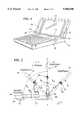
- FIG. 1is a view of a portable computer incorporating hinge assemblies according to an embodiment of the present invention.
- FIG. 2is a schematic view of the rotation of the display housing relative to the computer base in the embodiment of FIG. 1.
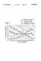
- FIG. 3is a graph of torque vs. angular position of the display housing relative to the computer base according to an embodiment of the present invention.
- FIG. 4is an exploded view of a hinge assembly according to the preferred embodiment of the present invention.
- FIG. 5is a top view of a hinge assembly according to the preferred embodiment of the present invention.
- FIG. 6is a sectional view of the hinge assembly of FIG. 5.
- FIG. 7is an exploded view of a hinge assembly according to an embodiment of the present invention.
- FIG. 8is a sectional view illustrating the hinge assembly according to an embodiment of the present invention.
- FIG. 9is a view of a hinge assembly detail showing how the hinge assembly is installed into the computer base part.
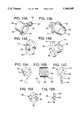
- FIGS. 10A and 10Bare views of a clutch mechanism according to an embodiment of the present invention.
- FIG. 10Cis a side sectional view of a clutch mechanism according to an embodiment of the present invention.
- FIG. 10Dis an end view of a clutch mechanism according to an embodiment of the present invention.
- FIG. 11is a side view of an assembly of a mounting arm and a pivot shaft according to an embodiment of the present invention.
- FIGS. 12A and 12Bare views of a friction bushing according to an embodiment of the present invention.
- FIG. 12Cis an end view of a friction bushing according to an embodiment of the present invention.
- FIG. 12Dis a side, sectional view of the friction bushing of FIG. 12C according to an embodiment of the present invention.
- FIGS. 13A and 13Bare views of a spring isolator according to the preferred embodiment of the present invention.
- FIGS. 14A and 14Bare views of a spring bushing according to an embodiment of the present invention.
- FIG. 15Ais a left end view of a torsion spring according to an embodiment of the present invention.
- FIG. 15Bis a side view of a torsion spring according to an embodiment of the present invention.
- FIG. 15Cis a right end view of a torsion spring according to an embodiment of the present invention.
- FIG. 16Ais an end view of a spring support according to an embodiment of the present invention.
- FIG. 16Bis a side view of a spring support according to an embodiment of the present invention.
- a devicesuch as a portable computer 10 that incorporates hinge assemblies 18 according to a first embodiment-of the present invention includes a base 12 and a display housing 14.
- the display housing 14is connected to the base 12 via the hinge assemblies 18.
- the display housingis rotatable relative to the base about a pivot axis 20 that is concentric with the center line of a pivot shaft 32 as shown in FIG. 4.
- the angle ⁇ between the side center line 24 of the display housing 14 and the side center line 26 of the base 12is 0° when the display housing is in a closed position. In the open position, the user can select the angle ⁇ of the display relative to the base to be any angle, usually within 150°.
- the weight of the display housing 14creates at the hinge assembly 18 a twisting force or torque about the pivot axis 20 (hereinafter called the “display torque”).
- the torque of concern hereis applied in a direction perpendicular to the plane passing through the pivot axis 20 and the point at which the force of the weight 35 of the display housing 14 is applied (hereinafter called the "torque plane").
- the torque generated by a forceis equal to the magnitude of the force multiplied by the straight line distance between the location where the force is applied and the pivot axis. If a force is applied directly along and toward the pivot axis, then there is no torque applied.
- An example of a torque created when a force is applied to an objectis a wrench used to turn a bolt. A torque has both a magnitude and a direction.
- the pivot axis 20passes through and along the centerline of the pivot shaft 32.
- the force generating the torqueis the weight of the display housing.
- the weightcan be represented by a single force applied at the location of the center of mass 34 of display housing 14.
- the center of mass 34is shown in FIG. 2 to be located at a distance R from the pivot axis.
- the straight-line distance X between the location of the force and the pivot axis 20is equal to R multiplied by cos( ⁇ ).
- the weight 35 of the display housing 14creates a clockwise torque about the pivot axis. This torque will hereinafter be referred to as an "opening torque" because it tends to cause the display housing to open relative to the computer base.
- FIG. 3shows a plot of the display torque vs. angular position of the display housing 14 relative to the base part 12. The plot shows that for angular displacements of the display relative to the base between 0° and 90°, the display torque is negative, for an angular position of 90°, the display torque is 0°, and for angular displacements greater than 90°, the display torque is positive.
- a negative torqueis referred to as a closing torque and a positive torque is referred to as an opening torque.
- the display housing 14is removably attached to an arm 38 or a similar mechanism.
- the arm 38is fixedly attached to a pivot shaft 32, the center of which is coincident with the pivot axis 20.
- the pivot shaft 32may be attached to a mounting feature 40 on the arm 38 or integral to the arm.
- the arm 38is attached to the pivot shaft 32 and the display housing 14 as shown in FIG. 1 such that the pivot shaft is perpendicular to the side edges 15 and 16 of the display housing and parallel with the lower edge 17 of the display housing.
- a spring isolator 46is slidably engaged with the pivot shaft 32.
- Spring isolator 46prevents spring 60 from coming into contact with pivot shaft 32 and support arm 38, thereby preventing wear particles and noise due to metal to metal contact.
- the spring isolator 46has an inner cylindrical surface 48 which encompasses the pivot shaft 32 about the circumference of the pivot shaft and along a portion of the length of the pivot shaft.
- the spring isolator 46has an outer flange surface 50 protruding radially from the outer cylindrical surface 52. As shown in FIG. 4, when the spring isolator 46 is slidably engaged with the pivot shaft 32, the outer flange surface 50 abuts the inner surface 39 of the arm 38.
- the inner surface 39 of the arm 38has an outer flange opening 41 sized to receive the outer surface 54 of a protrusion 53 on the surface 50 of spring isolator 46.
- the outer surface 54 of the protrusion 53 on the spring isolatorslidably engages with the opening 41 in the arm 38, preventing the spring isolator from rotating relative to the arm.
- the protrusion 53also has a cavity 56 sized to receive a first end 62 of the torsion spring 60.
- the spring isolator 46has an inner flange surface 51 protruding generally radially from the outer cylindrical surface 52. As shown in FIG. 13B, the inner flange surface 51 has a helical shape to correspond to the helical shape of the first coil 66 of the torsion spring 60. In the preferred embodiment the torsion spring 60 has a shape as shown in FIGS. 15A, 15B and 15C.
- a torsion spring 60is slidably engaged with the spring isolator 46, the inner diameter 68 of the torsion spring 60 is larger than the outer cylindrical surface 52 of the spring isolator to provide clearance between the torsion spring and spring isolator.
- the surface 67 of the first coil 66 of the torsion spring 60abuts the inner flange surface 51 of the spring isolator 46.
- the first end 62 of the torsion spring 60slidably engages the cavity 56 of the protrusion 53 on the spring isolator 46.
- the first coil 66 of the torsion springabuts surface 51 on the spring isolator.
- the inner flange surface 51by abutting the first coil 66 of the torsion spring 60, constrains and prevents the torsion spring from deflecting along the axial length of the torsion spring. Therefore, compressive and tensile torques applied to the torsion spring will result in circumferential compression and elongation, respectively.
- the service life of a torsion springis increased when deflection along the axial length of the torsion spring is avoided.
- the pivot shaft 32 and spring isolator 46remain fixed relative to the mounting arm, and therefore also rotate about the pivot axis.
- the pivot shaft 32does not rotate relative to the spring isolator 46. Therefore, the spring isolator 46 acts as a bearing element between the torsion spring 60 and the pivot shaft.
- the spring isolator 46is replaced by a spring bushing 74 and a spring support 80.
- the spring bushing 74is slidably engaged with an opening 43 in the mounting arm 38 sized to receive the spring bushing.
- the inner surface 86 of the spring bushingabuts the inner surface 39 of the arm.
- the spring bushing 74has a cavity 78 sized to receive a first end 62 of the torsion spring 60.
- the spring bushing 74is attached to the arm 38 away from the attachment location of the pivot shaft 32 by a distance sufficient to allow the pivot shaft to be engaged with the mounting arm distance sufficient to allow the pivot shaft to be engaged with the mounting arm.
- the outer perimeter 75 of the spring bushingabuts the pivot shaft 32.
- the spring support 80is slidably engaged with the pivot shaft 32, the inner diameter 84 of the spring support contacting the pivot shaft.
- the spring support 80is an annular ring having a C-shape 82.
- the opening of the C-shape 82is larger than the outer surface 76 of the spring bushing 74 such that when the spring support 80 is slidably engaged with the pivot shaft 32, the C-shape allows the first surface 81 of the spring support to abut the inner surface 39 of the mounting arm 38.
- a torsion spring 60 having a first protruding end 62is slidably engaged with the pivot shaft 32, such that the inner diameter 68 of the torsion spring .contacts the pivot shaft.
- the outer surface 67 of the first coil 66abuts the second surface 83 of the spring support 80.
- the spring support 80supports the torsion spring 60 for the same purposes that the spring isolator 46 supported the torsion spring in the preferred embodiment described above.
- the outer diameter 85 of the spring support 80may be larger or smaller than the outer diameter 70 of the torsion spring 60.
- the torsion spring 60When the torsion spring 60 is slidably engaged with the pivot shaft 32, the torsion spring must be angularly oriented as shown in FIG. 7 such that the first end 62 of the torsion spring aligns with and passes through the C-shape 82 of the spring support 80, and aligns with the cavity 78 in the spring bushing 74.
- the first end 62 of the torsion spring 60slidably engages with the cavity 78 spring bushing 60, preventing the first end of the torsion spring from rotating relative to the spring bushing or arm 38.
- the hinge assemblies 18include a clutch mechanism 100 which is removably attached to the base part 12 at the attachment boss 120 using one or more screws or similar fasteners.
- the clutch mechanism 100has a generally cylindrical inner surface 104.
- the inner surface 104has a keyway 106 which extends along the length of the inner surface.
- the clutch mechanism 100also has a second spring bushing 90 with a cavity 92 sized to receive the second end 64 of the torsion spring 60.
- the second spring bushing 90is located perpendicularly to the inner surface 104 of the clutch mechanism 100.
- the second end 64 of the torsion spring 60is fixed relative to the base part 12, by slidably engaging the second end 64 of the torsion spring 60 into a cavity 92 in a second spring bushing 90 attached to or integral with the clutch mechanism 100. Once slidably engaged into the second spring bushing 90, the second end 64 of the torsion spring 60 is angularly fixed relative to the clutch mechanism 100 and the base part 12.
- a friction bushing 126is slidably engaged with the clutch mechanism 100.
- the friction bushing 126has a generally cylindrical outer surface 128 having a key 130 protruding radially from and extending along the length of the outer surface.
- the cross-section of the key 130may be any convenient shape for slidably engaging the key with the keyway 106 in the clutch mechanism 100.
- the outer surface 128 of the friction bushing 126is slightly smaller than the inner surface 104 of the clutch mechanism 100.
- the friction bushing 126has a flange 134 which protrudes radially from the outer surface 128 of the friction bushing at a first end 136 away from a second end 138, which is first inserted into the clutch housing.
- the flange 134has an inner surface 135 which abuts an outer surface 108 of the clutch mechanism 100 when the friction bushing 126 is slidably engaged with the clutch mechanism.
- the flange 134acts as a stop to prevent the friction bushing 126 from being inserted too far into the clutch mechanism 100.
- the friction bushing 126also has a first inner surface 140 which is generally cylindrical, having a plurality of grooves or splines 142 along the length of the first inner surface, the depth of which form a second inner surface 144 having a radius larger than the first inner surface by an amount equal to the depth of the splines.
- the first inner surface 140 of the friction bushing 126is smaller than the diameter of the pivot shaft 32 by about 0.01 inches.
- the pivot shaft 32is slidably engaged with the friction bushing 126, using a press fit. Frictional forces between the inner surface 140 of the friction bushing 126 and the pivot shaft 32 are generated as the pivot shaft is rotated relative to the friction bushing.
- the diameter of the inner surface 140 of the friction bushing 126 or the pivot shaft 32may be changed to increase or decrease the amount of interference and therefore the amount of friction between the first inner surface of the friction bushing and the pivot shaft.
- the "spring torque"varies substantially linearly with (i.e. in proportion to) the angular displacement of the display housing 14 relative to the base part 12.
- the magnitude and direction of the spring torqueis plotted for any angular orientation of the display housing 14 relative to the base 12.
- the torsion spring 60is under no tensile or compressive stress when the angular displacement of the display housing 14 relative to the base part 12 is 90°.
- a tensile or stretching stressis applied to the torsion spring 60, resulting in an "opening torque" applied to the pivot shaft 32.
- a compressive stressis applied to the torsion spring 60, resulting in a "closing torque” applied to the pivot shaft 32.
- the torquesmay be added to one another to determine the resultant or net torque applied to the pivot axis.
- the torsion spring 60is selected such that its spring constant provides a torque which, when combined with the torque generated by the display housing 14 weight, results in a combined torque as shown in FIG. 3.
- the graph in FIG. 3shows that for an angular orientation of the display housing 14 relative to the base part 12 of between 50° and 140°, the combined torque upon the pivot shaft 32 is nearly 0.
- the maximum combined torque upon the pivot shaft 32 over this rangeis 0.04 inch-pounds. Over the range of 40° to 150°, the combined torque is still very low, reaching a maximum magnitude of 0.12 inch-pounds.
- the combined torqueis an "opening torque" which varies between a maximum of 0.9 inch-pounds when the angle between the display housing 14 and the base part 12 is 0°, to a minimum of 0.2 inch-pounds when the angle between the display housing and the base part is 40°.
- a userin order to fully close the display housing, a user must exert a closing torque on the pivot shaft 32 to overcome the combined "opening torque.”
- the combined "opening torque" existing when the display is in the closed positionfurther provides a "pop-up” feature such that when the latch holding the display housing closed against the base is released, the display housing angularly deflects or pops-up a distance sufficient to assist the user in grasping the display.
- a torsion spring 60may be selected that has a different spring constant to provide more or less spring torque for a given angular displacement of the display housing 14 relative to the base 12. Such a selection would produce a different combined torque for a given angular position of the display housing 14.
- the function of the clutch mechanism 100is to provide rotational friction to the movement of the display housing 14 relative to the base part 12.
- the display housing 14will be in a state of near equilibrium, meaning that only a slight force will be required to adjust the display housing.
- the friction created by the clutch mechanism 100is desirable to allow the display housing to remain in the angular position desired by the user.
- the pivot shaft 32is hollow having a generally cylindrical inner surface 33.
- the diameter 35 of the inner surface 33is large enough to allow a cable 140 or wiring harness or the like to press through the pivot shaft 32.
- the cable 140may be used to provide electrical signals grounding, shielding or the like from the base part 12 to the display housing 14.
- the cable 140By passing the cable 140 through the pivot shaft 32, as the display housing 14 is rotated relative to the base part 12, the cable undergoes torsional strain, but does not undergo strain perpendicular to its length. Cables or wires are highly susceptible to fatigue when subjected to crimping or bending forces. Therefore, by providing a channel to constrain the wire and subject the wire primarily to torsional strain, the service life of the wire will be increased.
Landscapes
- Engineering & Computer Science (AREA)
- Computer Hardware Design (AREA)
- Theoretical Computer Science (AREA)
- Physics & Mathematics (AREA)
- Human Computer Interaction (AREA)
- General Engineering & Computer Science (AREA)
- General Physics & Mathematics (AREA)
- Microelectronics & Electronic Packaging (AREA)
- Computer Networks & Wireless Communication (AREA)
- Mathematical Physics (AREA)
- Pivots And Pivotal Connections (AREA)
Abstract
Description
The present invention relates to hinges used with devices having displays, such as portable computers.
Portable computers, including those known as laptops, notebooks and palmtops, usually have a display screen housing that is hinged to a base part which carries the keyboard. The display housing is movable about the hinge(s) between a closed position against the base part and an open position with the display and keyboard exposed for use.
The hinges typically incorporate mechanisms that rely on friction to hold the display housing in the open position at the angle relative to the computer base preferred by the user.
The friction required by the hinge mechanism to support the weight of the display housing may be so great that two hands are required to open the computer. A user must use one hand to hold the base while using the other hand to pivot the display about the hinge. Furthermore, the display housing has a tendency to slam closed against the computer base.
In accordance with one aspect of the present invention, a hinge assembly for a device, such as a portable computer, is provided with a clutch mechanism that includes a friction component and a torsion spring component. The spring counteracts the weight of the display housing of the open computer. In this way, the friction component of the clutch mechanism need only be strong enough to support the open display housing during times when the computer is subjected to vibration or the like. This solution reduces the amount of force necessary to adjust the angular position of the display housing. One hand may be used to open and close the device. The reduced friction force allows use of a smaller, lighter friction component.
As another aspect of this invention, the weight-counteracting effect of the torsion spring-tends to prevent the display from inadvertently or accidentally slamming closed against the base.
As another aspect of this invention, the pivot shaft has an inner surface of a sufficient diameter to allow a cable to pass through at least one of the hinge assemblies to carry electronic signals between the display and the base.
The foregoing and additional features and advantages of the invention will be more readily apparent from the following detailed description thereof, which proceeds with reference to the accompanying drawings.
FIG. 1 is a view of a portable computer incorporating hinge assemblies according to an embodiment of the present invention.
FIG. 2 is a schematic view of the rotation of the display housing relative to the computer base in the embodiment of FIG. 1.
FIG. 3 is a graph of torque vs. angular position of the display housing relative to the computer base according to an embodiment of the present invention.
FIG. 4 is an exploded view of a hinge assembly according to the preferred embodiment of the present invention.
FIG. 5 is a top view of a hinge assembly according to the preferred embodiment of the present invention.
FIG. 6 is a sectional view of the hinge assembly of FIG. 5.
FIG. 7 is an exploded view of a hinge assembly according to an embodiment of the present invention.
FIG. 8 is a sectional view illustrating the hinge assembly according to an embodiment of the present invention.
FIG. 9 is a view of a hinge assembly detail showing how the hinge assembly is installed into the computer base part.
FIGS. 10A and 10B are views of a clutch mechanism according to an embodiment of the present invention.
FIG. 10C is a side sectional view of a clutch mechanism according to an embodiment of the present invention.
FIG. 10D is an end view of a clutch mechanism according to an embodiment of the present invention.
FIG. 11 is a side view of an assembly of a mounting arm and a pivot shaft according to an embodiment of the present invention.
FIGS. 12A and 12B are views of a friction bushing according to an embodiment of the present invention.
FIG. 12C is an end view of a friction bushing according to an embodiment of the present invention.
FIG. 12D is a side, sectional view of the friction bushing of FIG. 12C according to an embodiment of the present invention.
FIGS. 13A and 13B are views of a spring isolator according to the preferred embodiment of the present invention.
FIGS. 14A and 14B are views of a spring bushing according to an embodiment of the present invention.
FIG. 15A is a left end view of a torsion spring according to an embodiment of the present invention.
FIG. 15B is a side view of a torsion spring according to an embodiment of the present invention.
FIG. 15C is a right end view of a torsion spring according to an embodiment of the present invention.
FIG. 16A is an end view of a spring support according to an embodiment of the present invention.
FIG. 16B is a side view of a spring support according to an embodiment of the present invention.
Referring to FIG. 1, a device such as aportable computer 10 that incorporateshinge assemblies 18 according to a first embodiment-of the present invention includes abase 12 and adisplay housing 14. Thedisplay housing 14 is connected to thebase 12 via thehinge assemblies 18. The display housing is rotatable relative to the base about apivot axis 20 that is concentric with the center line of apivot shaft 32 as shown in FIG. 4.
As shown in FIG. 2, the angle θ between theside center line 24 of thedisplay housing 14 and theside center line 26 of thebase 12 is 0° when the display housing is in a closed position. In the open position, the user can select the angle θ of the display relative to the base to be any angle, usually within 150°.
The weight of thedisplay housing 14 creates at the hinge assembly 18 a twisting force or torque about the pivot axis 20 (hereinafter called the "display torque"). The torque of concern here is applied in a direction perpendicular to the plane passing through thepivot axis 20 and the point at which the force of theweight 35 of thedisplay housing 14 is applied (hereinafter called the "torque plane").
In general, the torque generated by a force is equal to the magnitude of the force multiplied by the straight line distance between the location where the force is applied and the pivot axis. If a force is applied directly along and toward the pivot axis, then there is no torque applied. An example of a torque created when a force is applied to an object is a wrench used to turn a bolt. A torque has both a magnitude and a direction.
In the case of thedisplay housing 14 attached to thecomputer base part 12, as shown in FIGS. 1 and 2, thepivot axis 20 passes through and along the centerline of thepivot shaft 32. The force generating the torque is the weight of the display housing. For simplicity of discussion, as shown in FIG. 2, the weight can be represented by a single force applied at the location of the center ofmass 34 ofdisplay housing 14. The center ofmass 34 is shown in FIG. 2 to be located at a distance R from the pivot axis.
For any angular orientation θ of thedisplay housing 14 relative to thebase 12, the straight-line distance X between the location of the force and thepivot axis 20 is equal to R multiplied by cos(θ).
Accordingly, when thedisplay housing 14 is in the first position shown in FIG. 2, with an angle θ1 equal to 90°, there is no torque applied by theweight 35 of thedisplay housing 14 about thepivot axis 20. As mentioned above, a torque is only created when a force is applied at some distance away from and perpendicular to the "torque plane." When the display housing is in the first position, the weight of the display is acting in a direction parallel to the "torque plane," and therefore there is no torque created about the pivot axis.
When the display housing is oriented in the second position as shown in FIG. 2, where the angle between theside center line 24 of thedisplay housing 14 and theside center line 26 of thecomputer base 12 is greater than 90°, theweight 35 of thedisplay housing 14 creates a clockwise torque about the pivot axis. This torque will hereinafter be referred to as an "opening torque" because it tends to cause the display housing to open relative to the computer base.
When thedisplay housing 14 is in the third position as shown in FIG. 2, a counter-clockwise torque is applied to thepivot axis 20 by theweight 35 of thedisplay housing 14. This torque will hereinafter be referred to as a "closing torque" because it tends to cause thedisplay housing 14 to close relative to thecomputer base part 12.
Therefore, for any angular displacement of thedisplay housing 14 relative to thebase part 12, there may be a torque applied to thepivot axis 20 by theweight 35 of the display. This torque varies non-linearly with the angular position of the display housing. For the preferred embodiment, FIG. 3 shows a plot of the display torque vs. angular position of thedisplay housing 14 relative to thebase part 12. The plot shows that for angular displacements of the display relative to the base between 0° and 90°, the display torque is negative, for an angular position of 90°, the display torque is 0°, and for angular displacements greater than 90°, the display torque is positive. As noted above, a negative torque is referred to as a closing torque and a positive torque is referred to as an opening torque.
In accordance with the embodiment as shown in FIGS. 1 and 8, thedisplay housing 14 is removably attached to anarm 38 or a similar mechanism. As shown in FIGS. 4, 5, 7 and 11, thearm 38 is fixedly attached to apivot shaft 32, the center of which is coincident with thepivot axis 20. Thepivot shaft 32 may be attached to a mountingfeature 40 on thearm 38 or integral to the arm. Thearm 38 is attached to thepivot shaft 32 and thedisplay housing 14 as shown in FIG. 1 such that the pivot shaft is perpendicular to the side edges 15 and 16 of the display housing and parallel with thelower edge 17 of the display housing.
In the preferred embodiment as shown in FIGS. 4, 5 and 6, aspring isolator 46 is slidably engaged with thepivot shaft 32.Spring isolator 46 preventsspring 60 from coming into contact withpivot shaft 32 andsupport arm 38, thereby preventing wear particles and noise due to metal to metal contact. Thespring isolator 46 has an innercylindrical surface 48 which encompasses thepivot shaft 32 about the circumference of the pivot shaft and along a portion of the length of the pivot shaft.
As shown in FIGS. 13A and 13B, thespring isolator 46 has anouter flange surface 50 protruding radially from the outercylindrical surface 52. As shown in FIG. 4, when thespring isolator 46 is slidably engaged with thepivot shaft 32, theouter flange surface 50 abuts theinner surface 39 of thearm 38. Theinner surface 39 of thearm 38 has anouter flange opening 41 sized to receive theouter surface 54 of aprotrusion 53 on thesurface 50 ofspring isolator 46. When thespring isolator 46 fully slidably engages thepivot shaft 32, theouter surface 54 of theprotrusion 53 on the spring isolator slidably engages with theopening 41 in thearm 38, preventing the spring isolator from rotating relative to the arm. Theprotrusion 53 also has acavity 56 sized to receive afirst end 62 of thetorsion spring 60.
Thespring isolator 46 has aninner flange surface 51 protruding generally radially from the outercylindrical surface 52. As shown in FIG. 13B, theinner flange surface 51 has a helical shape to correspond to the helical shape of thefirst coil 66 of thetorsion spring 60. In the preferred embodiment thetorsion spring 60 has a shape as shown in FIGS. 15A, 15B and 15C.
Atorsion spring 60 is slidably engaged with thespring isolator 46, theinner diameter 68 of thetorsion spring 60 is larger than the outercylindrical surface 52 of the spring isolator to provide clearance between the torsion spring and spring isolator. Thesurface 67 of thefirst coil 66 of thetorsion spring 60 abuts theinner flange surface 51 of thespring isolator 46. Thefirst end 62 of thetorsion spring 60 slidably engages thecavity 56 of theprotrusion 53 on thespring isolator 46.
Therefore, when thetorsion spring 60 is fully slidably engaged with thespring isolator 46, thefirst coil 66 of the torsion spring abutssurface 51 on the spring isolator. Theinner flange surface 51, by abutting thefirst coil 66 of thetorsion spring 60, constrains and prevents the torsion spring from deflecting along the axial length of the torsion spring. Therefore, compressive and tensile torques applied to the torsion spring will result in circumferential compression and elongation, respectively. The service life of a torsion spring is increased when deflection along the axial length of the torsion spring is avoided.
As the mountingarm 38 is rotated about thepivot axis 20, thepivot shaft 32 andspring isolator 46 remain fixed relative to the mounting arm, and therefore also rotate about the pivot axis. Thepivot shaft 32 does not rotate relative to thespring isolator 46. Therefore, thespring isolator 46 acts as a bearing element between thetorsion spring 60 and the pivot shaft.
In another embodiment as shown in FIG. 7, thespring isolator 46 is replaced by aspring bushing 74 and aspring support 80. Thespring bushing 74 is slidably engaged with anopening 43 in the mountingarm 38 sized to receive the spring bushing. When thespring bushing 74 is fully slidably engaged with the mountingarm 38, theinner surface 86 of the spring bushing abuts theinner surface 39 of the arm.
As shown in FIGS. 14A and 14B, thespring bushing 74 has acavity 78 sized to receive afirst end 62 of thetorsion spring 60. Thespring bushing 74 is attached to thearm 38 away from the attachment location of thepivot shaft 32 by a distance sufficient to allow the pivot shaft to be engaged with the mounting arm distance sufficient to allow the pivot shaft to be engaged with the mounting arm. When thespring bushing 74 is slidably engaged with theopening 43 in the mountingarm 38, theouter perimeter 75 of the spring bushing abuts thepivot shaft 32.
As shown in FIG. 7, thespring support 80 is slidably engaged with thepivot shaft 32, theinner diameter 84 of the spring support contacting the pivot shaft. In one embodiment, as shown in FIGS. 16A and 16B, thespring support 80 is an annular ring having a C-shape 82. The opening of the C-shape 82 is larger than theouter surface 76 of thespring bushing 74 such that when thespring support 80 is slidably engaged with thepivot shaft 32, the C-shape allows thefirst surface 81 of the spring support to abut theinner surface 39 of the mountingarm 38.
As shown in FIG. 7, atorsion spring 60 having a firstprotruding end 62 is slidably engaged with thepivot shaft 32, such that theinner diameter 68 of the torsion spring .contacts the pivot shaft. When thetorsion spring 60 is slidably engaged with thepivot shaft 32, theouter surface 67 of thefirst coil 66 abuts thesecond surface 83 of thespring support 80. Thespring support 80 supports thetorsion spring 60 for the same purposes that thespring isolator 46 supported the torsion spring in the preferred embodiment described above. Theouter diameter 85 of thespring support 80 may be larger or smaller than theouter diameter 70 of thetorsion spring 60.
When thetorsion spring 60 is slidably engaged with thepivot shaft 32, the torsion spring must be angularly oriented as shown in FIG. 7 such that thefirst end 62 of the torsion spring aligns with and passes through the C-shape 82 of thespring support 80, and aligns with thecavity 78 in thespring bushing 74. Thefirst end 62 of thetorsion spring 60 slidably engages with thecavity 78spring bushing 60, preventing the first end of the torsion spring from rotating relative to the spring bushing orarm 38.
As shown in FIGS. 4 and 7, thehinge assemblies 18 include aclutch mechanism 100 which is removably attached to thebase part 12 at theattachment boss 120 using one or more screws or similar fasteners. As shown in FIGS. 10A, 10B, 10C and 10D, theclutch mechanism 100 has a generally cylindricalinner surface 104. Theinner surface 104 has akeyway 106 which extends along the length of the inner surface. Theclutch mechanism 100 also has asecond spring bushing 90 with acavity 92 sized to receive thesecond end 64 of thetorsion spring 60. In the preferred embodiment, thesecond spring bushing 90 is located perpendicularly to theinner surface 104 of theclutch mechanism 100.
In the preferred embodiment, thesecond end 64 of thetorsion spring 60 is fixed relative to thebase part 12, by slidably engaging thesecond end 64 of thetorsion spring 60 into acavity 92 in asecond spring bushing 90 attached to or integral with theclutch mechanism 100. Once slidably engaged into thesecond spring bushing 90, thesecond end 64 of thetorsion spring 60 is angularly fixed relative to theclutch mechanism 100 and thebase part 12.
As shown in FIGS. 5, 6, 7 and 8, afriction bushing 126 is slidably engaged with theclutch mechanism 100. As shown in FIGS. 12C and 12D, thefriction bushing 126 has a generally cylindricalouter surface 128 having a key 130 protruding radially from and extending along the length of the outer surface. The cross-section of the key 130 may be any convenient shape for slidably engaging the key with thekeyway 106 in theclutch mechanism 100. Theouter surface 128 of thefriction bushing 126 is slightly smaller than theinner surface 104 of theclutch mechanism 100. When thefriction bushing 126 is slidably engaged with theclutch mechanism 100, the key 130 in the friction bushing slidably engages thekeyway 106 in the clutch mechanism to prevent angular displacement of the friction bushing relative to the clutch mechanism.
Thefriction bushing 126 has aflange 134 which protrudes radially from theouter surface 128 of the friction bushing at afirst end 136 away from asecond end 138, which is first inserted into the clutch housing. Theflange 134 has aninner surface 135 which abuts anouter surface 108 of theclutch mechanism 100 when thefriction bushing 126 is slidably engaged with the clutch mechanism. Theflange 134 acts as a stop to prevent the friction bushing 126 from being inserted too far into theclutch mechanism 100.
As shown in FIGS. 12A and 12B, thefriction bushing 126 also has a firstinner surface 140 which is generally cylindrical, having a plurality of grooves orsplines 142 along the length of the first inner surface, the depth of which form a secondinner surface 144 having a radius larger than the first inner surface by an amount equal to the depth of the splines. In the preferred embodiment, the firstinner surface 140 of thefriction bushing 126 is smaller than the diameter of thepivot shaft 32 by about 0.01 inches.
Thepivot shaft 32 is slidably engaged with thefriction bushing 126, using a press fit. Frictional forces between theinner surface 140 of thefriction bushing 126 and thepivot shaft 32 are generated as the pivot shaft is rotated relative to the friction bushing.
In related embodiments, the diameter of theinner surface 140 of thefriction bushing 126 or thepivot shaft 32 may be changed to increase or decrease the amount of interference and therefore the amount of friction between the first inner surface of the friction bushing and the pivot shaft.
As shown in FIGS. 4, 7 and 9, as thearm 38 attached to thedisplay housing 14 is rotated relative to thebase part 12, thefirst end 62 of thetorsion spring 60 is rotated relative to thesecond end 64 of the torsion spring. This rotation generates a rotational torque upon thetorsion spring 60. In response to this torque, thetorsion spring 60 will generate a rotational torque in the opposite direction equal to the angular displacement of the torsion spring multiplied by the spring constant of the torsion spring (hereinafter called a "spring torque").
In the preferred embodiment, the "spring torque" varies substantially linearly with (i.e. in proportion to) the angular displacement of thedisplay housing 14 relative to thebase part 12. In FIG. 3, the magnitude and direction of the spring torque is plotted for any angular orientation of thedisplay housing 14 relative to thebase 12.
In the preferred embodiment, as shown in FIG. 3, thetorsion spring 60 is under no tensile or compressive stress when the angular displacement of thedisplay housing 14 relative to thebase part 12 is 90°. When the angle of thedisplay housing 14 relative to thebase part 12 is less than 90°, a tensile or stretching stress is applied to thetorsion spring 60, resulting in an "opening torque" applied to thepivot shaft 32. When the angle between thedisplay housing 14 and thebase 12 is greater than 90°, a compressive stress is applied to thetorsion spring 60, resulting in a "closing torque" applied to thepivot shaft 32.
In general, when more than one torque acts upon a single axis, the torques may be added to one another to determine the resultant or net torque applied to the pivot axis. In the preferred embodiment, as shown in FIG. 3, thetorsion spring 60 is selected such that its spring constant provides a torque which, when combined with the torque generated by thedisplay housing 14 weight, results in a combined torque as shown in FIG. 3.
The graph in FIG. 3 shows that for an angular orientation of thedisplay housing 14 relative to thebase part 12 of between 50° and 140°, the combined torque upon thepivot shaft 32 is nearly 0. The maximum combined torque upon thepivot shaft 32 over this range is 0.04 inch-pounds. Over the range of 40° to 150°, the combined torque is still very low, reaching a maximum magnitude of 0.12 inch-pounds. For angular displacements of thedisplay housing 14 relative to thebase part 12 of between 0° and 40°, the combined torque is an "opening torque" which varies between a maximum of 0.9 inch-pounds when the angle between thedisplay housing 14 and thebase part 12 is 0°, to a minimum of 0.2 inch-pounds when the angle between the display housing and the base part is 40°.
Therefore, in order to fully close the display housing, a user must exert a closing torque on thepivot shaft 32 to overcome the combined "opening torque." The combined "opening torque" existing when the display is in the closed position further provides a "pop-up" feature such that when the latch holding the display housing closed against the base is released, the display housing angularly deflects or pops-up a distance sufficient to assist the user in grasping the display.
In related embodiments, atorsion spring 60 may be selected that has a different spring constant to provide more or less spring torque for a given angular displacement of thedisplay housing 14 relative to thebase 12. Such a selection would produce a different combined torque for a given angular position of thedisplay housing 14.
The function of theclutch mechanism 100 is to provide rotational friction to the movement of thedisplay housing 14 relative to thebase part 12. When the "display torque" and the "spring torque" are nearly equal, thedisplay housing 14 will be in a state of near equilibrium, meaning that only a slight force will be required to adjust the display housing. The friction created by theclutch mechanism 100 is desirable to allow the display housing to remain in the angular position desired by the user.
In the preferred embodiment as shown in FIGS. 4, 6, 7, 8 and 9, thepivot shaft 32 is hollow having a generally cylindricalinner surface 33. Thediameter 35 of theinner surface 33 is large enough to allow acable 140 or wiring harness or the like to press through thepivot shaft 32. Thecable 140 may be used to provide electrical signals grounding, shielding or the like from thebase part 12 to thedisplay housing 14. By passing thecable 140 through thepivot shaft 32, as thedisplay housing 14 is rotated relative to thebase part 12, the cable undergoes torsional strain, but does not undergo strain perpendicular to its length. Cables or wires are highly susceptible to fatigue when subjected to crimping or bending forces. Therefore, by providing a channel to constrain the wire and subject the wire primarily to torsional strain, the service life of the wire will be increased.
In view of the many possible embodiments to which the principles of our invention may be put, it should be recognized that the detailed embodiments are illustrative only and should not be taken as limiting the scope of our invention. For example, whiledevice 10 is shown as a portable computer device, any device with a hinged display, such as a medical device, calculator, photo copier control panel, etc, would fall within the spirit and scope of this invention. Rather, we claim as our invention all such embodiments as may come within the scope and spirit of the following claims and equivalents thereto.
Claims (15)
1. A portable computer having a display housing and a base attached to the display housing by a hinge assembly, the hinge assembly comprising:
a pivot shaft attaching the display housing to the base and allowing the display housing to pivot relative to the base, the display housing generating a first torque on the pivot shaft in proportion to the angular orientation of the display housing;
a coil torsion spring for providing a second torque on the pivot shaft in proportion to the angular orientation of the display housing, the spring surrounding at least a portion of the pivot shaft, the spring having a first end and a second end;
a mechanism for constraining the first end of the torsion spring relative to the housing; and
a clutch mechanism having a first inner surface for slidably engaging the pivot shaft, the first inner surface of the clutch mechanism being sized to fit tightly around the pivot shaft so as to continuously resist rotation of the pivot shaft, a mechanism for constraining the second end of the torsion spring, and a mechanism removably attaching the clutch mechanism to the base.
2. The portable computer of claim 1 wherein for any angular orientation of the display housing between 0° and 150° relative to the base, the sum of the torque provided by the display and the torque provided by the spring does not exceed 1.0 inch-pounds.
3. The portable computer of claim 1 wherein for any angular orientation of the display housing between 50° and 140° relative to the base, the sum of the torque provided by the display and the torque provided by the spring does not exceed 0.1 inch-pounds.
4. The portable computer of claim 1 including a clutch mechanism having a first inner surface with a plurality of grooves, the first inner surface for providing rotational friction.
5. The portable computer of claim 1 wherein the pivot shaft has an axis and an inner surface of a diameter sized to allow a cable to slide along the axis of the pivot shaft.
6. A portable computer having a base and a display housing attached to the base by a hinge assembly, the hinge assembly comprising:
an arm removably attached to the display housing;
a pivot shaft attached to the arm, extending perpendicular to the arm;
a torsion spring having a first end and a second end, the torsion spring slidably engaged with the pivot shaft;
a mechanism for constraining the first end of the torsion spring relative to the arm;
a clutch mechanism having a first inner surface for slidably engaging the pivot shaft, the first inner surface of the clutch mechanism being sized to fit tightly around the pivot shaft so as to continuously resist rotation of the pivot shaft, a mechanism for constraining the second end of the torsion spring, and a mechanism for removably attaching the clutch mechanism to the base;
whereby the display housing may be rotated to a selectable angular position and remain in the selected position.
7. The portable computer of claim 6 wherein the first end of the torsion spring protrudes axially from the torsion spring.
8. The portable computer of claim 6 in which the selectable angular position is selectable from the range of at least 50 degrees to 140 degrees.
9. The portable computer of claim 6 further comprising a bearing element slidably engaged with the pivot shaft and the torsion spring.
10. The portable computer of claim 6 wherein the pivot shaft has an inner diameter sized to allow a cable to be slidably engaged with the pivot shaft.
11. A portable computer comprising:
a base;
a display; and
a hinge coupling the display to the base, the hinge including a pivot shaft coupled to the display, a coiled torsion spring that tends to urge the display relative to the base so as to exert a force therebetween, the spring having a first end and a second end, the spring slidably engaged with the pivot shaft, a mechanism for constraining the first end of the torsion spring relative to the display, a clutch mechanism coupled to the base and having a first inner surface for slidably engaging the pivot shaft, the first inner surface of the clutch mechanism being sized to fit tightly around the pivot shaft so as to continuously resist rotation of the pivot shaft, and a mechanism for constraining the second end of the torsion spring.
12. The computer of claim 11 in which:
the base and display define a base-display angle; and
a torque exerted by the torsion spring on the display substantially matches a second torque exerted by gravity on the display, when the base is horizontal, for a range of base-display angles.
13. The computer of claim 11 in which said range spans at least 40 degrees.
14. The computer of claim 11 in which said range of base-display angles is from about 50 to about 140 degrees.
15. The computer of claim 11 in which the hinge additionally includes a mechanism having a first inner surface with a plurality of grooves, the first inner surface for providing rotational friction.
Priority Applications (1)
| Application Number | Priority Date | Filing Date | Title |
|---|---|---|---|
| US08/253,048US5566048A (en) | 1994-06-02 | 1994-06-02 | Hinge assembly for a device having a display |
Applications Claiming Priority (1)
| Application Number | Priority Date | Filing Date | Title |
|---|---|---|---|
| US08/253,048US5566048A (en) | 1994-06-02 | 1994-06-02 | Hinge assembly for a device having a display |
Publications (1)
| Publication Number | Publication Date |
|---|---|
| US5566048Atrue US5566048A (en) | 1996-10-15 |
Family
ID=22958625
Family Applications (1)
| Application Number | Title | Priority Date | Filing Date |
|---|---|---|---|
| US08/253,048Expired - LifetimeUS5566048A (en) | 1994-06-02 | 1994-06-02 | Hinge assembly for a device having a display |
Country Status (1)
| Country | Link |
|---|---|
| US (1) | US5566048A (en) |
Cited By (175)
| Publication number | Priority date | Publication date | Assignee | Title |
|---|---|---|---|---|
| US5636102A (en)* | 1995-09-21 | 1997-06-03 | International Business Machines Corporation | Portable information processing apparatus with hinge for enlarged LCD display |
| US5751544A (en)* | 1995-10-06 | 1998-05-12 | Samsung Electronics Co., Ltd. | Computer with a detachable hinged LCD display cable connection |
| US5796576A (en)* | 1995-10-04 | 1998-08-18 | Samsung Electronics Co., Ltd. | Notebook computer having a hinge device enabling a display unit to be separable from a main body |
| US5835139A (en)* | 1997-04-08 | 1998-11-10 | Lg Electronics Inc. | Computer having liquid crystal display between frames attached at the edges |
| GB2325557A (en)* | 1997-05-24 | 1998-11-25 | Lg Electronics Inc | Mounting a display module |
| US5844774A (en)* | 1996-04-08 | 1998-12-01 | Kabushiki Kaisha Toshiba | Portable apparatus with housing for containing functional elements and with bracket for supporting the housing |
| DE29719236U1 (en)* | 1997-09-04 | 1998-12-03 | Lg Electronics Inc., Seoul/Soul | Display for a portable data processing device with a gear-shaped hinge |
| US5896622A (en)* | 1998-02-17 | 1999-04-27 | Lu; Sheng-Nan | Hinge device |
| US5949642A (en)* | 1996-10-16 | 1999-09-07 | Samsung Electronics Co., Ltd. | Hinge assembly for a portable computer |
| US5950281A (en)* | 1998-07-16 | 1999-09-14 | Lu; Sheng-Nan | Hinge mechanism |
| US6002457A (en)* | 1997-04-08 | 1999-12-14 | Lg Lcd, Inc. | Computer having liquid crystal display |
| US6020942A (en)* | 1997-04-08 | 2000-02-01 | Lg Lcd, Inc. | Computer having liquid crystal display |
| US6050738A (en)* | 1995-07-15 | 2000-04-18 | Rittal-Werk Rudolf Loh Gmbh | Device for fitting a control panel to the lower front edge of a control device |
| US6064565A (en)* | 1997-09-04 | 2000-05-16 | International Business Machines Corporation | LCD assembly and information processing apparatus |
| EP0989351A3 (en)* | 1995-03-22 | 2000-05-17 | Canon Kabushiki Kaisha | Support structure and display apparatus equipped therewith |
| US6076232A (en)* | 1997-05-30 | 2000-06-20 | Nec Corporation | Hinge structure for electronic apparatus |
| US6101676A (en)* | 1998-01-27 | 2000-08-15 | Dell Usa, L.P. | Adjustable clutch hinge assembly for portable computer |
| US6106181A (en)* | 1996-01-29 | 2000-08-22 | Rittal-Werk Rudolf Loh Gmbh & Co. Kg | Control apparatus with control panel |
| US6145797A (en)* | 1996-12-04 | 2000-11-14 | Canon Kabushiki Kaisha | Lock device, display apparatus and liquid crystal apparatus |
| US6163452A (en)* | 1999-11-05 | 2000-12-19 | Dell Usa, L.P. | Display screen assembly apparatus and method |
| US6170120B1 (en)* | 1999-06-14 | 2001-01-09 | Lu Sheng-Nan | Notebook computer hinge |
| US6198625B1 (en)* | 1999-06-03 | 2001-03-06 | Micron Electronics, Inc. | Hinge assembly for a portable computer |
| US6202256B1 (en)* | 1998-09-04 | 2001-03-20 | Compaq Computer Corporation | Hinge system for a portable computer |
| US6219230B1 (en) | 1998-12-01 | 2001-04-17 | Samsung Electronics Co., Ltd. | Portable computer with improved assembly design |
| US6223393B1 (en) | 1999-07-09 | 2001-05-01 | International Business Machines Corporation | Redundant hinge element for a notebook computer |
| US6249426B1 (en) | 1999-08-30 | 2001-06-19 | Dell Usa Corp | Portable computer having a sealed hinge clutch |
| US6261024B1 (en)* | 1997-08-14 | 2001-07-17 | Webasto Karosseriesysteme Gmbh | Rocker device for an openable motor vehicle roof and process for mounting one such device |
| GB2358950A (en)* | 1998-11-10 | 2001-08-08 | Lg Philips Lcd Co Ltd | Computer having a flat panel display |
| US6381809B2 (en)* | 2000-01-18 | 2002-05-07 | Chuo Hatsujo Kabushiki Kaisha | Frictional hinge device and a portable business machine into which the frictional hinge device is incorporated |
| US6389643B1 (en)* | 1999-07-26 | 2002-05-21 | Compaq Computer Corporation | Modular hinge |
| US6411501B1 (en)* | 1998-11-11 | 2002-06-25 | Lg Philips Lcd Co., Ltd. | Portable computer and method for mounting a flat display device module |
| US6446308B1 (en)* | 2001-01-17 | 2002-09-10 | International Business Machines Corporation | Tilt hinge |
| EP1238861A1 (en)* | 2001-02-22 | 2002-09-11 | Yazaki Corporation | Vehicle door hinge harness |
| US6453509B1 (en)* | 2001-02-19 | 2002-09-24 | Samsung Electronics Co., Ltd. | Hinge arrangement for a display apparatus |
| US20020155740A1 (en)* | 2001-04-18 | 2002-10-24 | Masaki Sawada | Coupling device and folding electronic apparatus using the same |
| US20020162192A1 (en)* | 2001-05-07 | 2002-11-07 | Gwag Su-Man | Clip-type friction hinge device |
| US20020167789A1 (en)* | 2001-05-11 | 2002-11-14 | Cema Technologies, Inc. | Hinge assembly for rotatably mounting a display to a surface |
| WO2002098123A3 (en)* | 2001-05-30 | 2003-01-16 | Robert P Jackson Iii | Portable display monitor |
| US6510588B2 (en) | 2000-05-30 | 2003-01-28 | Nokia Mobile Phones Ltd. | Turning mechanism for providing turning motion, and hinged electronic device |
| US6513197B2 (en) | 2000-11-22 | 2003-02-04 | Torqmaster, Inc. | Friction hinge with pop-up feature |
| US20030024073A1 (en)* | 2001-08-03 | 2003-02-06 | Ting-Hui Chih | Apparatus for supporting a monitor |
| EP0877313A3 (en)* | 1997-05-06 | 2003-06-04 | Samsung Electronics Co., Ltd. | Pivot device and portable computer with pivot device |
| US6601269B2 (en)* | 2000-03-22 | 2003-08-05 | Sugatsune Kogyo Co., Ltd. | Hinge Assembly |
| US6607236B2 (en)* | 2001-12-05 | 2003-08-19 | Ventra Group Inc. | Door support system |
| US6618240B1 (en) | 1998-11-10 | 2003-09-09 | Lg.Philips Lcd Co., Ltd. | Computer having a flat panel display |
| US6656053B2 (en)* | 2001-04-13 | 2003-12-02 | Chuck Chang | Automatically restorable universal connector |
| US6657856B1 (en)* | 2002-07-08 | 2003-12-02 | Lu Sheng-Nan | Hinge for a notebook computer |
| US6671929B1 (en)* | 2002-09-13 | 2004-01-06 | Shin Zu Shing Co., Ltd. | Hinge for a notebook computer |
| US20040008485A1 (en)* | 2002-07-15 | 2004-01-15 | Takashi Naganawa | Electronic apparatus |
| US6682252B2 (en)* | 2002-03-01 | 2004-01-27 | Steelcase Development Corporation | Torsional energy joint for seating unit |
| US20040049883A1 (en)* | 2002-09-17 | 2004-03-18 | Chin-Fa Huang | Hinge device |
| US20040060152A1 (en)* | 2002-09-28 | 2004-04-01 | Heung-Kee Kim | Damper hinge |
| US20040078932A1 (en)* | 2002-10-28 | 2004-04-29 | Ding-Hone Su | Torque regulator device for hinge assembly |
| KR100432320B1 (en)* | 2001-07-11 | 2004-05-22 | 캠아이티(주) | a hinge of LCD-monitor |
| US20040107539A1 (en)* | 2002-12-10 | 2004-06-10 | Lu Sheng-Nan | Hinge for a notebook computer |
| KR100443613B1 (en)* | 2001-12-27 | 2004-08-09 | 엘지전자 주식회사 | Hinge structure for plane-type display device |
| US20040155861A1 (en)* | 2002-05-30 | 2004-08-12 | Jackson Iii Robert P. | Portable display monitor |
| US20040165345A1 (en)* | 1998-06-30 | 2004-08-26 | Young Un Bang | Portable information processing apparatus |
| US20040174668A1 (en)* | 2001-04-18 | 2004-09-09 | Sellers Charles A. | System and method for pivotably securing display housing to computer system |
| US6807712B2 (en)* | 2000-06-29 | 2004-10-26 | Nokia Mobile Phones Ltd. | Hinge having engagement surface to restrain rotational movement and electronic device containing such a hinge |
| US20040251389A1 (en)* | 2003-06-13 | 2004-12-16 | Innovative Office Products, Inc. | Tilter apparatus for electronic device having bias assembly |
| US6838810B1 (en) | 1997-03-21 | 2005-01-04 | Chunghwa Picture Tubes, Ltd. | Flat-panel display mounting system for portable computer |
| US20050052838A1 (en)* | 2003-09-04 | 2005-03-10 | Chun-Liang Yeh | Portable device and rotating and positioning mechanism thereof |
| US20050086767A1 (en)* | 2003-10-25 | 2005-04-28 | Chuang Wen-Pin | Adjustable stepless hinge shaft |
| US20050168930A1 (en)* | 1998-10-23 | 2005-08-04 | Kim Jong H. | Portable computer and method for mounting a flat panel display device thereon |
| US20060010649A1 (en)* | 2004-07-17 | 2006-01-19 | Hon Hai Precision Industry Co., Ltd. | Hinge assembly for media player |
| US20060023411A1 (en)* | 2004-07-27 | 2006-02-02 | Samsung Electronics Co., Ltd. | Swing hinge apparatus and portable terminal with the same |
| US20060060735A1 (en)* | 2004-09-23 | 2006-03-23 | Oddsen Odd N Jr | Tilter apparatus having bias assembly |
| USD518484S1 (en)* | 2004-08-18 | 2006-04-04 | Fujitsu Limited | Personal computer |
| US20060081757A1 (en)* | 2004-10-19 | 2006-04-20 | Hirohide Okahara | Display device |
| US20060112518A1 (en)* | 2004-11-26 | 2006-06-01 | Fih Co.,Ltd | Cover restricting mechanism |
| US20060112515A1 (en)* | 2004-12-01 | 2006-06-01 | Takehiko Konja | Folding mechanism |
| US7055215B1 (en) | 2003-12-19 | 2006-06-06 | Apple Computer, Inc. | Hinge assembly |
| US20060130278A1 (en)* | 2004-12-21 | 2006-06-22 | Asustek Computer Inc. | Hinge device with locking function |
| US20060163314A1 (en)* | 2005-01-25 | 2006-07-27 | Huan-Tsung Lin | Torsion adjusting module |
| US20060203440A1 (en)* | 2005-03-09 | 2006-09-14 | Lev Jeffrey A | Computer with hinge post and hinge mount and related methods |
| US20060227154A1 (en)* | 2005-04-12 | 2006-10-12 | Hewlett-Packard Development Company, Lp | Electronic device display panel |
| US20060288532A1 (en)* | 2005-06-28 | 2006-12-28 | Samsung Electronics Co., Ltd. | Door hinge device and electronic appliances having the same |
| US20070013654A1 (en)* | 2005-06-30 | 2007-01-18 | Takamitsu Kawai | Image recording apparatus and method for producing image recording apparatus |
| US20070022639A1 (en)* | 2005-07-29 | 2007-02-01 | Honda Motor Co, Ltd. | Shooter for snow remover |
| US7171911B1 (en)* | 2003-02-26 | 2007-02-06 | Midwest Folding Products | Mobile folding table having a lifting assist center torsion bar and lift off casters |
| US20070084014A1 (en)* | 2005-10-18 | 2007-04-19 | Wen-Chieh Tseng | Hinge structure and foldable electronic device using the same |
| US20070097613A1 (en)* | 2005-10-27 | 2007-05-03 | Tracy Mark S | Computer display biasing mechanism |
| US20070107163A1 (en)* | 2003-12-23 | 2007-05-17 | Barnett Ricky W | Modular hinge for handheld electronic devices |
| US20070118025A1 (en)* | 2005-10-17 | 2007-05-24 | Janne Lampinen | Patient monitor |
| US20070121282A1 (en)* | 2005-11-29 | 2007-05-31 | Inventec Corporation | Hinge structure for notebook computer |
| US20070186380A1 (en)* | 2006-02-15 | 2007-08-16 | Lg Electronics Inc. | Hinge assembly and mobile device having the same |
| US20070252056A1 (en)* | 2006-03-27 | 2007-11-01 | Southco, Inc. | Display Mounting Apparatus |
| US20070279854A1 (en)* | 2006-06-02 | 2007-12-06 | Sung-Ming Song | Protecting device for electrical cable |
| US20080010779A1 (en)* | 2006-07-11 | 2008-01-17 | Compal Electronics, Inc. | Pivot mechanism and electronic apparatus using the same |
| US20080040887A1 (en)* | 2006-08-16 | 2008-02-21 | Dickerson Harry L | Friction hinge for electronic apparatus |
| US20080078064A1 (en)* | 2006-09-01 | 2008-04-03 | Compal Electronics, Inc. | Hinge structure and foldable apparatus using the same |
| CN100396942C (en)* | 2004-12-30 | 2008-06-25 | 华硕电脑股份有限公司 | Pivot device with stop function |
| US20080151478A1 (en)* | 2006-12-21 | 2008-06-26 | Jr-Jiun Chern | Hinge for laptop computer |
| US20080151477A1 (en)* | 2006-12-21 | 2008-06-26 | Jr-Jiun Chern | Hinge for laptop computer |
| US20080249406A1 (en)* | 2007-04-06 | 2008-10-09 | Aloka Co., Ltd. | Ultrasound diagnostic apparatus |
| DE102007051563B3 (en)* | 2007-10-29 | 2008-11-13 | Jr-Jiun Chern | Articulation device for use in notebook, has hinge pin, and rotable device, which is rotable installed on hinge pin, where rotable device has two stretcher elements and socket |
| DE102007049546B3 (en)* | 2007-10-16 | 2008-12-04 | Jr-Jiun Chern | Joint arrangement for use with notebook-computer, comprises primary coupling element, which is installed with hinge bolt, and primary coupling element that has connecting section and pivoting section |
| US7492421B1 (en) | 1997-07-03 | 2009-02-17 | Lg Display Co., Ltd. | Case for liquid crystal display |
| US20090089973A1 (en)* | 2007-10-03 | 2009-04-09 | Universal Scientific Industrial Co., Ltd. | Friction hinge having an electrical heating component, and method of controlling friction force in a friction hinge |
| US20090089975A1 (en)* | 2007-10-09 | 2009-04-09 | Jr-Jiun Chern | Hinge Assembly |
| US20090279258A1 (en)* | 2008-05-12 | 2009-11-12 | Moore David A | Hinge connector with liquid coolant path |
| WO2009158111A1 (en)* | 2008-06-26 | 2009-12-30 | Stethoscope Technologies, Inc.1/2 | Asymmetric tension adjustment mechanism and head piece including same |
| US20100092845A1 (en)* | 2008-10-13 | 2010-04-15 | Spare Bradley L | Portable computer battery structures |
| US20100092022A1 (en)* | 2008-10-13 | 2010-04-15 | Ron Hopkinson | Portable computer speaker grill structures |
| US20100091451A1 (en)* | 2008-10-13 | 2010-04-15 | Hendren Keith J | Battery connector structures for electronic devices |
| US20100091452A1 (en)* | 2008-10-13 | 2010-04-15 | John Raff | Portable computer structures |
| US20100091444A1 (en)* | 2008-10-13 | 2010-04-15 | Gavin Reid | Portable computer hard drive structures |
| US20100090847A1 (en)* | 2008-10-13 | 2010-04-15 | Hendren Keith J | Portable computer battery indicator |
| US20100088853A1 (en)* | 2008-10-13 | 2010-04-15 | Degner Brett W | Portable computer clutch structures |
| US20100281653A1 (en)* | 2008-08-19 | 2010-11-11 | Zong-Ying Lin | Bidirectional Hinge |
| US20100289391A1 (en)* | 2009-05-13 | 2010-11-18 | Hong Fu Jin Precision Industry (Shenzhen) Co., Ltd. | Hinge assembly and electronic device using the same |
| WO2011014162A1 (en)* | 2009-07-28 | 2011-02-03 | Hewlett-Packard Development Company, L.P. | Hinge |
| US20110084188A1 (en)* | 2009-10-08 | 2011-04-14 | Innovative Office Products, Inc. | Tilter for positioning an electronic device |
| US20110140496A1 (en)* | 2009-10-14 | 2011-06-16 | King Furniture (Australia) Pty Ltd. | Hinge assembly |
| CN101408220B (en)* | 2007-10-09 | 2011-06-22 | 鸿富锦精密工业(深圳)有限公司 | Rotary brake structure and components |
| US20110156563A1 (en)* | 2009-12-25 | 2011-06-30 | Kabushiki Kaisha Toshiba | Electronic apparatus |
| US20110186608A1 (en)* | 2010-01-29 | 2011-08-04 | Yakima Products, Inc. | Car top carrier lid support |
| US20110235275A1 (en)* | 2010-03-26 | 2011-09-29 | Wistron Corporation | Portable electronic device having a pop-up keyboard cross-reference to related application |
| US20120057282A1 (en)* | 2008-08-26 | 2012-03-08 | Hon Hai Precision Industry Co., Ltd. | Flat-panel display monitor |
| CN101451574B (en)* | 2007-12-07 | 2012-03-28 | 鸿富锦精密工业(深圳)有限公司 | Rotation brake structure |
| US20130010424A1 (en)* | 2011-07-08 | 2013-01-10 | Apple Inc. | Computer hinge with hollow and partially annular clutch |
| USD684965S1 (en)* | 2011-12-15 | 2013-06-25 | Google Inc. | Notebook computer housing |
| USD684966S1 (en)* | 2011-12-15 | 2013-06-25 | Google Inc. | Notebook computer housing |
| USD684964S1 (en)* | 2011-12-15 | 2013-06-25 | Google Inc. | Notebook computer housing |
| US8477487B2 (en) | 2010-04-05 | 2013-07-02 | Apple Inc. | Computer hinge having a hollow clutch |
| USD686613S1 (en)* | 2011-12-15 | 2013-07-23 | Google Inc. | Notebook computer housing |
| JP2013179125A (en)* | 2012-02-28 | 2013-09-09 | Icom Inc | Mounting structure of access cover |
| US20130343806A1 (en)* | 2012-06-26 | 2013-12-26 | Koncept Technologies Inc. | Self biased joint and method |
| USD704185S1 (en)* | 2012-11-06 | 2014-05-06 | Google Inc. | Notebook computer housing |
| USD705772S1 (en)* | 2012-11-06 | 2014-05-27 | Google Inc. | Notebook computer housing |
| USD708604S1 (en)* | 2012-11-06 | 2014-07-08 | Google Inc. | Notebook computer housing |
| CN103926976A (en)* | 2013-01-16 | 2014-07-16 | 宏碁股份有限公司 | Rotating shaft structure and electronic device |
| US20140268726A1 (en)* | 2013-03-15 | 2014-09-18 | Scott S YU | System to allocate luminance |
| USD717786S1 (en)* | 2012-11-06 | 2014-11-18 | Google Inc. | Notebook computer housing |
| US8934805B2 (en) | 2012-12-14 | 2015-01-13 | Brother Kogyo Kabushiki Kaisha | Image recording apparatus |
| US9025211B2 (en) | 2012-07-06 | 2015-05-05 | Brother Kogyo Kabushiki Kaisha | Image reading apparatus |
| US9207712B1 (en) | 2012-07-13 | 2015-12-08 | Google Inc. | Notebook computer with improved display positioning |
| US9277812B2 (en) | 2010-07-08 | 2016-03-08 | Southco, Inc. | Display support with first and second arms and mechanism for maintaining constant orientation of the plane bisecting the range of rotation of the second arm relative to a support base |
| USD756349S1 (en)* | 2014-12-26 | 2016-05-17 | Intel Corporation | Portable computing device with low profile hinge |
| US20160161994A1 (en)* | 2013-07-19 | 2016-06-09 | Hewlett-Packard Development Company L.P. | Fiber hinge |
| US9372513B1 (en)* | 2013-09-27 | 2016-06-21 | Google Inc. | Coupling element for hinged electronic device |
| US9383777B1 (en) | 2013-09-27 | 2016-07-05 | Google Inc. | Notebook computer with lid mounting for translational movement |
| USD775624S1 (en)* | 2014-12-23 | 2017-01-03 | Intel Corporation | Computer hinge having a high angle of rotation |
| EP3048469A4 (en)* | 2013-09-17 | 2017-08-30 | Neoviewkolon Co., Ltd. | Head-up display |
| US20170298982A1 (en)* | 2014-09-29 | 2017-10-19 | Helwett-Packard Development Company, L.P. | Hinge assembly with compressible sleeve |
| US9823631B1 (en) | 2013-10-01 | 2017-11-21 | Google Llc | Notebook computer with motorized display positioning |
| US20180226777A1 (en)* | 2017-02-07 | 2018-08-09 | Microsoft Technology Licensing, Llc | Cable-retention device assembly |
| DE102017203800A1 (en) | 2017-03-08 | 2018-09-13 | Bayerische Motoren Werke Aktiengesellschaft | DISPLACEMENT LOADING DEVICE FOR INDUCTIVELY CHARGING AN ENERGY STORAGE OF A MOTOR VEHICLE |
| US20180364767A1 (en)* | 2017-06-19 | 2018-12-20 | Fujitsu Limited | Hinge connector and electronic apparatus |
| US10168746B2 (en) | 2015-11-20 | 2019-01-01 | Hewlett-Packard Development Company, L.P. | Hinge mechanism for a computing device |
| US10227808B2 (en) | 2015-11-20 | 2019-03-12 | Microsoft Technology Licensing, Llc | Hinged device |
| US10241548B2 (en) | 2016-12-09 | 2019-03-26 | Microsoft Technology Licensing, Llc | Computing device employing a self-spacing hinge assembly |
| US10253804B2 (en) | 2017-01-24 | 2019-04-09 | Microsoft Technology Licensing, Llc | Hinged device |
| US10287810B2 (en)* | 2015-02-19 | 2019-05-14 | Southco, Inc. | Pivot device and method of generating asymmetric friction torque |
| US10296044B2 (en) | 2017-06-08 | 2019-05-21 | Microsoft Technology Licensing, Llc | Hinged device |
| US20190169896A1 (en)* | 2017-12-05 | 2019-06-06 | Dell Products L.P. | Information Handling System Dual Axis Mono-Barrel Hinge |
| US10344510B2 (en) | 2017-06-16 | 2019-07-09 | Microsoft Technology Licensing, Llc | Hinged device |
| US10364598B2 (en) | 2016-09-02 | 2019-07-30 | Microsoft Technology Licensing, Llc | Hinged device |
| US10474203B2 (en) | 2016-09-01 | 2019-11-12 | Microsoft Technology Licensing, Llc | Hinged device |
| US20190354143A1 (en)* | 2017-01-05 | 2019-11-21 | Fujitsu Client Computing Limited | Information Processing Terminal And Hinge Unit |
| US10550617B2 (en)* | 2018-01-05 | 2020-02-04 | LEECO Technologies Corporation | Self-closing hinge |
| US10641318B2 (en) | 2016-12-09 | 2020-05-05 | Microsoft Technology Licensing, Llc | Hinged device |
| CN111255318A (en)* | 2020-01-17 | 2020-06-09 | 刘知迪 | Hinge combination with built-in electric wire |
| US10739827B2 (en)* | 2018-01-08 | 2020-08-11 | Samsung Medison Co. Ltd. | Supporting device for display device |
| JPWO2019044322A1 (en)* | 2017-08-28 | 2020-11-12 | 日本精機株式会社 | Head-up display device |
| WO2021060571A1 (en)* | 2019-09-24 | 2021-04-01 | 엘지전자 주식회사 | Portable electronic device |
| US11079043B2 (en)* | 2018-09-19 | 2021-08-03 | Chuo Hatsujo Kabushiki Kaisha | Cable supporting device |
| US11131423B2 (en) | 2016-03-07 | 2021-09-28 | Southco, Inc. | Display support arm assembly for mounting a display |
| US20210372462A1 (en)* | 2019-02-14 | 2021-12-02 | Opple Lighting Co., Ltd. | Variable torsion spring damping rotating shaft |
| US11627209B2 (en)* | 2016-06-14 | 2023-04-11 | Microsoft Technology Licensing, Llc | Hinge with free-stop function |
| CN116057247A (en)* | 2020-08-06 | 2023-05-02 | 世嘉智尼工业株式会社 | One-way brake hinge |
| US20240271678A1 (en)* | 2021-06-14 | 2024-08-15 | Reell Precision Manufacturing Corporation | Molded housing friction device having stable torque over temperature range |
| US20240393839A1 (en)* | 2023-05-26 | 2024-11-28 | Fositek Corporation | Wire-passable hinge |
| US12428887B2 (en) | 2016-06-14 | 2025-09-30 | Microsoft Technology Licensing, Llc | Hinge mechanism |
Citations (14)
| Publication number | Priority date | Publication date | Assignee | Title |
|---|---|---|---|---|
| US4944481A (en)* | 1988-06-30 | 1990-07-31 | Next, Inc. | Balanced monitor stand |
| US4976007A (en)* | 1989-06-22 | 1990-12-11 | Quanta Computer Inc. | Connecting device for portable computers |
| US4986763A (en)* | 1989-03-06 | 1991-01-22 | Dynabook Technologies Cororation | Contact strip-to-flex bushing connector |
| US5028913A (en)* | 1989-06-01 | 1991-07-02 | Nhk Spring Co., Ltd. | Angle adjusting device in display device |
| US5037231A (en)* | 1988-12-21 | 1991-08-06 | Nhk Spring Co., Ltd. | Joint device for connecting two rotatable members |
| US5041818A (en)* | 1990-05-21 | 1991-08-20 | Lapro Corporation | Lid with movement control device |
| US5043846A (en)* | 1989-04-10 | 1991-08-27 | Seiko Epson Corporation | Pivotable display unit support structure for electronic apparatus |
| US5077551A (en)* | 1988-11-30 | 1991-12-31 | Kabushiki Kaisha Toshiba | Display panel open/closed detection mechanism, and portable electronic apparatus using the same |
| US5131779A (en)* | 1990-06-01 | 1992-07-21 | Crete Systems, Inc. | Connecting shaft assembly for the screen cover of a portable computer |
| US5144290A (en)* | 1988-10-31 | 1992-09-01 | Kabushiki Kaisha Toshiba | Display unit attachment device |
| US5142738A (en)* | 1990-07-24 | 1992-09-01 | Nhk Spring Co., Ltd. | Hinge device |
| US5173837A (en)* | 1990-10-15 | 1992-12-22 | Compaq Computer Corporation | Hinge with two-towed clutch spring for suppressing electromagnetic interference for laptop personal computers |
| US5217316A (en)* | 1990-10-12 | 1993-06-08 | Nhk Spring Co., Ltd. | Slow-acting rotation shaft device |
| US5240319A (en)* | 1990-08-22 | 1993-08-31 | Brother Kogyo Kabushiki Kaisha | Upper body opening/closing mechanism for electronic equipment |
- 1994
- 1994-06-02USUS08/253,048patent/US5566048A/ennot_activeExpired - Lifetime
Patent Citations (14)
| Publication number | Priority date | Publication date | Assignee | Title |
|---|---|---|---|---|
| US4944481A (en)* | 1988-06-30 | 1990-07-31 | Next, Inc. | Balanced monitor stand |
| US5144290A (en)* | 1988-10-31 | 1992-09-01 | Kabushiki Kaisha Toshiba | Display unit attachment device |
| US5077551A (en)* | 1988-11-30 | 1991-12-31 | Kabushiki Kaisha Toshiba | Display panel open/closed detection mechanism, and portable electronic apparatus using the same |
| US5037231A (en)* | 1988-12-21 | 1991-08-06 | Nhk Spring Co., Ltd. | Joint device for connecting two rotatable members |
| US4986763A (en)* | 1989-03-06 | 1991-01-22 | Dynabook Technologies Cororation | Contact strip-to-flex bushing connector |
| US5043846A (en)* | 1989-04-10 | 1991-08-27 | Seiko Epson Corporation | Pivotable display unit support structure for electronic apparatus |
| US5028913A (en)* | 1989-06-01 | 1991-07-02 | Nhk Spring Co., Ltd. | Angle adjusting device in display device |
| US4976007A (en)* | 1989-06-22 | 1990-12-11 | Quanta Computer Inc. | Connecting device for portable computers |
| US5041818A (en)* | 1990-05-21 | 1991-08-20 | Lapro Corporation | Lid with movement control device |
| US5131779A (en)* | 1990-06-01 | 1992-07-21 | Crete Systems, Inc. | Connecting shaft assembly for the screen cover of a portable computer |
| US5142738A (en)* | 1990-07-24 | 1992-09-01 | Nhk Spring Co., Ltd. | Hinge device |
| US5240319A (en)* | 1990-08-22 | 1993-08-31 | Brother Kogyo Kabushiki Kaisha | Upper body opening/closing mechanism for electronic equipment |
| US5217316A (en)* | 1990-10-12 | 1993-06-08 | Nhk Spring Co., Ltd. | Slow-acting rotation shaft device |
| US5173837A (en)* | 1990-10-15 | 1992-12-22 | Compaq Computer Corporation | Hinge with two-towed clutch spring for suppressing electromagnetic interference for laptop personal computers |
Non-Patent Citations (2)
| Title |
|---|
| Teague, "4 Views of a Blue-Ribbon Product," Design News, pp. 56-64, May 9, 1994. |
| Teague, 4 Views of a Blue Ribbon Product, Design News, pp. 56 64, May 9, 1994.* |
Cited By (322)
| Publication number | Priority date | Publication date | Assignee | Title |
|---|---|---|---|---|
| EP0989351A3 (en)* | 1995-03-22 | 2000-05-17 | Canon Kabushiki Kaisha | Support structure and display apparatus equipped therewith |
| US6216989B1 (en) | 1995-03-22 | 2001-04-17 | Canon Kabushiki Kaisha | Support structure and display apparatus equipped with the support structure |
| US6050738A (en)* | 1995-07-15 | 2000-04-18 | Rittal-Werk Rudolf Loh Gmbh | Device for fitting a control panel to the lower front edge of a control device |
| US5636102A (en)* | 1995-09-21 | 1997-06-03 | International Business Machines Corporation | Portable information processing apparatus with hinge for enlarged LCD display |
| US5796576A (en)* | 1995-10-04 | 1998-08-18 | Samsung Electronics Co., Ltd. | Notebook computer having a hinge device enabling a display unit to be separable from a main body |
| US5751544A (en)* | 1995-10-06 | 1998-05-12 | Samsung Electronics Co., Ltd. | Computer with a detachable hinged LCD display cable connection |
| US6106181A (en)* | 1996-01-29 | 2000-08-22 | Rittal-Werk Rudolf Loh Gmbh & Co. Kg | Control apparatus with control panel |
| US5844774A (en)* | 1996-04-08 | 1998-12-01 | Kabushiki Kaisha Toshiba | Portable apparatus with housing for containing functional elements and with bracket for supporting the housing |
| JP3521168B2 (en) | 1996-04-08 | 2004-04-19 | 株式会社東芝 | Portable equipment |
| US5949642A (en)* | 1996-10-16 | 1999-09-07 | Samsung Electronics Co., Ltd. | Hinge assembly for a portable computer |
| US6145797A (en)* | 1996-12-04 | 2000-11-14 | Canon Kabushiki Kaisha | Lock device, display apparatus and liquid crystal apparatus |
| US6838810B1 (en) | 1997-03-21 | 2005-01-04 | Chunghwa Picture Tubes, Ltd. | Flat-panel display mounting system for portable computer |
| US20050088075A1 (en)* | 1997-03-21 | 2005-04-28 | Michele Bovio | Flat-panel display mounting system for portable computer |
| US20050088810A1 (en)* | 1997-03-21 | 2005-04-28 | Michele Bovio | Flat-panel display mounting system for portable computer |
| US20050078439A1 (en)* | 1997-03-21 | 2005-04-14 | Michele Bovio | Flat-panel display mounting system for portable computer |
| US20050082961A1 (en)* | 1997-03-21 | 2005-04-21 | Michele Bovio | Flat-panel display mounting system for portable computer |
| US20060198090A1 (en)* | 1997-03-21 | 2006-09-07 | Michele Bovio | Flat-panel display mounting system for portable computer |
| US20060198091A1 (en)* | 1997-03-21 | 2006-09-07 | Michele Bovio | Flat-panel display mounting system for portable computer |
| US20060209503A1 (en)* | 1997-03-21 | 2006-09-21 | Michele Bovio | Flat-panel display mounting system for portable computer |
| US20060209504A1 (en)* | 1997-03-21 | 2006-09-21 | Michele Bovio | Flat-panel display mounting system for portable computer |
| US7310222B2 (en) | 1997-03-21 | 2007-12-18 | Chunghwa Picture Tubes, Ltd. | Flat-panel display mounting system for portable computer |
| US7944522B2 (en) | 1997-04-08 | 2011-05-17 | Lg Display Co., Ltd. | Computer having liquid crystal display |
| US7944517B2 (en) | 1997-04-08 | 2011-05-17 | Lg Display, Co., Ltd. | Computer having liquid crystal display |
| US6373537B2 (en) | 1997-04-08 | 2002-04-16 | Lg. Philips Lcd Co., Ltd. | Computer having liquid crystal display between frames attached at the edges |
| US20020080299A1 (en)* | 1997-04-08 | 2002-06-27 | Yun Hee Young | Computer having liquid crystal display |
| US5835139A (en)* | 1997-04-08 | 1998-11-10 | Lg Electronics Inc. | Computer having liquid crystal display between frames attached at the edges |
| US5926237A (en)* | 1997-04-08 | 1999-07-20 | Lg Electronics Inc. | Computer having liquid crystal display |
| US6020942A (en)* | 1997-04-08 | 2000-02-01 | Lg Lcd, Inc. | Computer having liquid crystal display |
| US6002457A (en)* | 1997-04-08 | 1999-12-14 | Lg Lcd, Inc. | Computer having liquid crystal display |
| EP0877313A3 (en)* | 1997-05-06 | 2003-06-04 | Samsung Electronics Co., Ltd. | Pivot device and portable computer with pivot device |
| US6144423A (en)* | 1997-05-24 | 2000-11-07 | Lg Lcd, Inc. | Method of mounting liquid crystal display module and apparatus thereof |
| GB2325557B (en)* | 1997-05-24 | 2000-02-09 | Lg Electronics Inc | Mounting liquid crystal display module in a computer |
| US20070133159A1 (en)* | 1997-05-24 | 2007-06-14 | Kim Yong G | Method of mounting liquid crystal display module and apparatus thereof |
| US7193842B2 (en) | 1997-05-24 | 2007-03-20 | L.G.Phillips Lcd Co., Ltd. | Method of mounting liquid crystal display module and apparatus thereof |
| US5872606A (en)* | 1997-05-24 | 1999-02-16 | Lg Electronics Inc. | Method of mounting liquid crystal display module and apparatus thereof |
| FR2763711A1 (en)* | 1997-05-24 | 1998-11-27 | Lg Electronics Inc | METHOD AND DEVICE FOR MOUNTING A LIQUID CRYSTAL DISPLAY MODULE |
| US20040085274A1 (en)* | 1997-05-24 | 2004-05-06 | Kim Yong Gyu | Method of mounting liquid crystal display module and apparatus thereof |
| US7511949B2 (en) | 1997-05-24 | 2009-03-31 | Lg Display Co., Ltd. | Method of mounting liquid crystal display module and apparatus thereof |
| GB2325557A (en)* | 1997-05-24 | 1998-11-25 | Lg Electronics Inc | Mounting a display module |
| US6304432B1 (en) | 1997-05-24 | 2001-10-16 | Lg.Philips Lcd. Od., Ltd | Method of mounting liquid crystal display module and apparatus thereof |
| CN1078321C (en)* | 1997-05-30 | 2002-01-23 | 日本电气株式会社 | Hinged structure of electronic equipment |
| US6249951B1 (en) | 1997-05-30 | 2001-06-26 | Nec Corporation | Hinge structure for electronic apparatus |
| US6076232A (en)* | 1997-05-30 | 2000-06-20 | Nec Corporation | Hinge structure for electronic apparatus |
| US6098248A (en)* | 1997-05-30 | 2000-08-08 | Nec Corporation | Hinge structure for electronic apparatus |
| US7492421B1 (en) | 1997-07-03 | 2009-02-17 | Lg Display Co., Ltd. | Case for liquid crystal display |
| US6261024B1 (en)* | 1997-08-14 | 2001-07-17 | Webasto Karosseriesysteme Gmbh | Rocker device for an openable motor vehicle roof and process for mounting one such device |
| DE29719236U1 (en)* | 1997-09-04 | 1998-12-03 | Lg Electronics Inc., Seoul/Soul | Display for a portable data processing device with a gear-shaped hinge |
| DE19747761A1 (en)* | 1997-09-04 | 1999-03-11 | Lg Electronics Inc | Display for a portable data processing device with a gear-shaped hinge |
| DE19747761C2 (en)* | 1997-09-04 | 1999-06-17 | Lg Electronics Inc | Display for a portable data processing device with a gear-shaped hinge |
| US6064565A (en)* | 1997-09-04 | 2000-05-16 | International Business Machines Corporation | LCD assembly and information processing apparatus |
| US6101676A (en)* | 1998-01-27 | 2000-08-15 | Dell Usa, L.P. | Adjustable clutch hinge assembly for portable computer |
| US5896622A (en)* | 1998-02-17 | 1999-04-27 | Lu; Sheng-Nan | Hinge device |
| US20040165345A1 (en)* | 1998-06-30 | 2004-08-26 | Young Un Bang | Portable information processing apparatus |
| US7307833B2 (en)* | 1998-06-30 | 2007-12-11 | Lg.Philips Lcd Co., Ltd. | Portable information processing apparatus |
| US5950281A (en)* | 1998-07-16 | 1999-09-14 | Lu; Sheng-Nan | Hinge mechanism |
| US6564429B2 (en) | 1998-09-04 | 2003-05-20 | Hewlett Packard Development Company L.P. | Hinge system for a portable computer |
| US6202256B1 (en)* | 1998-09-04 | 2001-03-20 | Compaq Computer Corporation | Hinge system for a portable computer |
| US7907399B2 (en) | 1998-10-23 | 2011-03-15 | Lg Display Co., Ltd. | Portable computer and method for mounting a flat panel display device thereon |
| US7864138B2 (en) | 1998-10-23 | 2011-01-04 | Lg Display Co., Ltd. | Portable computer and method for mounting a flat panel display device thereon |
| US7828616B2 (en) | 1998-10-23 | 2010-11-09 | Lg Display Co., Ltd. | Method of forming a portable computer having a flat panel display device |
| US7885059B2 (en) | 1998-10-23 | 2011-02-08 | Lg Display Co., Ltd. | Portable computer and method for mounting a flat panel display device thereon |
| US20050168930A1 (en)* | 1998-10-23 | 2005-08-04 | Kim Jong H. | Portable computer and method for mounting a flat panel display device thereon |
| GB2358950B (en)* | 1998-11-10 | 2002-06-05 | Lg Philips Lcd Co Ltd | Computer having a flat panel display |
| US6618240B1 (en) | 1998-11-10 | 2003-09-09 | Lg.Philips Lcd Co., Ltd. | Computer having a flat panel display |
| GB2358950A (en)* | 1998-11-10 | 2001-08-08 | Lg Philips Lcd Co Ltd | Computer having a flat panel display |
| KR100508003B1 (en)* | 1998-11-11 | 2005-11-21 | 엘지.필립스 엘시디 주식회사 | How to combine a portable computer with its flat panel display |
| US7663871B2 (en) | 1998-11-11 | 2010-02-16 | Lg Display Co., Ltd. | Portable computer and method for mounting a flat panel display device module |
| US7170741B2 (en)* | 1998-11-11 | 2007-01-30 | Lg. Philips Lcd Co., Ltd. | Portable computer and method for mounting a flat panel display device module |
| US20020154476A1 (en)* | 1998-11-11 | 2002-10-24 | Cho Young Woo | Portable computer and method for mounting a flat panel display device module |
| US20060171106A1 (en)* | 1998-11-11 | 2006-08-03 | Cho Young W | Portable computer and method for mounting a flat panel display device module |
| US6411501B1 (en)* | 1998-11-11 | 2002-06-25 | Lg Philips Lcd Co., Ltd. | Portable computer and method for mounting a flat display device module |
| US6219230B1 (en) | 1998-12-01 | 2001-04-17 | Samsung Electronics Co., Ltd. | Portable computer with improved assembly design |
| US6359774B1 (en) | 1999-06-03 | 2002-03-19 | Micron Technology, Inc. | Hinge assembly for a portable computer |
| US6198625B1 (en)* | 1999-06-03 | 2001-03-06 | Micron Electronics, Inc. | Hinge assembly for a portable computer |
| US6170120B1 (en)* | 1999-06-14 | 2001-01-09 | Lu Sheng-Nan | Notebook computer hinge |
| US6223393B1 (en) | 1999-07-09 | 2001-05-01 | International Business Machines Corporation | Redundant hinge element for a notebook computer |
| US6389643B1 (en)* | 1999-07-26 | 2002-05-21 | Compaq Computer Corporation | Modular hinge |
| US6249426B1 (en) | 1999-08-30 | 2001-06-19 | Dell Usa Corp | Portable computer having a sealed hinge clutch |
| US6297946B2 (en) | 1999-08-30 | 2001-10-02 | Dell Usa, L.P. | Portable computer having a sealed hinge clutch |
| US6304433B2 (en) | 1999-08-30 | 2001-10-16 | Dell Usa, L.P. | Portable computer having a sealed hinge clutch |
| US6163452A (en)* | 1999-11-05 | 2000-12-19 | Dell Usa, L.P. | Display screen assembly apparatus and method |
| US6381809B2 (en)* | 2000-01-18 | 2002-05-07 | Chuo Hatsujo Kabushiki Kaisha | Frictional hinge device and a portable business machine into which the frictional hinge device is incorporated |
| EP1182316A4 (en)* | 2000-03-22 | 2004-05-26 | Sugatsune Kogyo | Hinge device |
| US6601269B2 (en)* | 2000-03-22 | 2003-08-05 | Sugatsune Kogyo Co., Ltd. | Hinge Assembly |
| US6510588B2 (en) | 2000-05-30 | 2003-01-28 | Nokia Mobile Phones Ltd. | Turning mechanism for providing turning motion, and hinged electronic device |
| US6807712B2 (en)* | 2000-06-29 | 2004-10-26 | Nokia Mobile Phones Ltd. | Hinge having engagement surface to restrain rotational movement and electronic device containing such a hinge |
| US6513197B2 (en) | 2000-11-22 | 2003-02-04 | Torqmaster, Inc. | Friction hinge with pop-up feature |
| US6446308B1 (en)* | 2001-01-17 | 2002-09-10 | International Business Machines Corporation | Tilt hinge |
| US6453509B1 (en)* | 2001-02-19 | 2002-09-24 | Samsung Electronics Co., Ltd. | Hinge arrangement for a display apparatus |
| EP1238861A1 (en)* | 2001-02-22 | 2002-09-11 | Yazaki Corporation | Vehicle door hinge harness |
| US6656053B2 (en)* | 2001-04-13 | 2003-12-02 | Chuck Chang | Automatically restorable universal connector |
| US6857879B2 (en)* | 2001-04-18 | 2005-02-22 | Matsushita Electric Industrial Co., Ltd. | Coupling device and folding electronic apparatus using the same |
| US6873522B2 (en)* | 2001-04-18 | 2005-03-29 | Hewlett-Packard Development Company, L.P. | System and method for pivotably securing display housing to computer system |
| US20040174668A1 (en)* | 2001-04-18 | 2004-09-09 | Sellers Charles A. | System and method for pivotably securing display housing to computer system |
| US20020155740A1 (en)* | 2001-04-18 | 2002-10-24 | Masaki Sawada | Coupling device and folding electronic apparatus using the same |
| US20020162192A1 (en)* | 2001-05-07 | 2002-11-07 | Gwag Su-Man | Clip-type friction hinge device |
| US6775884B2 (en)* | 2001-05-07 | 2004-08-17 | Gwag Su-Man | Clip-type friction hinge device |
| US6871384B2 (en) | 2001-05-11 | 2005-03-29 | Cema Technologies, Inc. | Hinge assembly for rotatably mounting a display to a surface |
| US20020167789A1 (en)* | 2001-05-11 | 2002-11-14 | Cema Technologies, Inc. | Hinge assembly for rotatably mounting a display to a surface |
| WO2002098123A3 (en)* | 2001-05-30 | 2003-01-16 | Robert P Jackson Iii | Portable display monitor |
| KR100432320B1 (en)* | 2001-07-11 | 2004-05-22 | 캠아이티(주) | a hinge of LCD-monitor |
| US20030024073A1 (en)* | 2001-08-03 | 2003-02-06 | Ting-Hui Chih | Apparatus for supporting a monitor |
| US6859356B2 (en)* | 2001-08-03 | 2005-02-22 | Benq Corporation | Apparatus for supporting a monitor |
| US6607236B2 (en)* | 2001-12-05 | 2003-08-19 | Ventra Group Inc. | Door support system |
| KR100443613B1 (en)* | 2001-12-27 | 2004-08-09 | 엘지전자 주식회사 | Hinge structure for plane-type display device |
| US6682252B2 (en)* | 2002-03-01 | 2004-01-27 | Steelcase Development Corporation | Torsional energy joint for seating unit |
| US20040155861A1 (en)* | 2002-05-30 | 2004-08-12 | Jackson Iii Robert P. | Portable display monitor |
| US6657856B1 (en)* | 2002-07-08 | 2003-12-02 | Lu Sheng-Nan | Hinge for a notebook computer |
| US20040008485A1 (en)* | 2002-07-15 | 2004-01-15 | Takashi Naganawa | Electronic apparatus |
| US6671929B1 (en)* | 2002-09-13 | 2004-01-06 | Shin Zu Shing Co., Ltd. | Hinge for a notebook computer |
| US6871383B2 (en)* | 2002-09-17 | 2005-03-29 | Hon Hai Precision Ind. Co., Ltd. | Hinge device |
| US20040049883A1 (en)* | 2002-09-17 | 2004-03-18 | Chin-Fa Huang | Hinge device |
| US6829807B2 (en)* | 2002-09-28 | 2004-12-14 | Heung-Kee Kim | Damper hinge |
| US20040060152A1 (en)* | 2002-09-28 | 2004-04-01 | Heung-Kee Kim | Damper hinge |
| US20040078932A1 (en)* | 2002-10-28 | 2004-04-29 | Ding-Hone Su | Torque regulator device for hinge assembly |
| US6813812B2 (en)* | 2002-12-10 | 2004-11-09 | Shin Zu Shing Co., Ltd. | Hinge for a notebook computer |
| US20040107539A1 (en)* | 2002-12-10 | 2004-06-10 | Lu Sheng-Nan | Hinge for a notebook computer |
| US7448330B2 (en) | 2003-02-26 | 2008-11-11 | Midwest Folding Products | Mobile folding table having a lifting assist center torsion bar and lift off casters |
| US20070199484A1 (en)* | 2003-02-26 | 2007-08-30 | Rivera Jeremias C Jr | Mobile folding table having a lifting assist center torsion bar and lift off casters |
| US7171911B1 (en)* | 2003-02-26 | 2007-02-06 | Midwest Folding Products | Mobile folding table having a lifting assist center torsion bar and lift off casters |
| US20050006543A1 (en)* | 2003-06-13 | 2005-01-13 | Innovative Office Products, Inc. | Tilter apparatus for electronic device having bias assembly |
| US7048242B2 (en)* | 2003-06-13 | 2006-05-23 | Innovative Office Products, Inc. | Tilter apparatus for electronic device having bias assembly |
| US7458549B2 (en)* | 2003-06-13 | 2008-12-02 | Innovative Office Products, Inc. | Tilter apparatus for electronic device having bias assembly |
| US7806378B2 (en)* | 2003-06-13 | 2010-10-05 | Innovative Office Products, Inc. | Tilter apparatus for electronic device having bias assembly |
| US7472458B2 (en) | 2003-06-13 | 2009-01-06 | Innovative Office Products, Inc. | Tilter apparatus for electronic device having bias assembly |
| US20090078841A1 (en)* | 2003-06-13 | 2009-03-26 | Innovative Office Products, Inc. | Tilter apparatus for electronic device having bias assembly |
| US20060197003A1 (en)* | 2003-06-13 | 2006-09-07 | Innovative Office Products, Inc. | Tilter apparatus for electronic device having bias assembly |
| US20040251389A1 (en)* | 2003-06-13 | 2004-12-16 | Innovative Office Products, Inc. | Tilter apparatus for electronic device having bias assembly |
| US20050052838A1 (en)* | 2003-09-04 | 2005-03-10 | Chun-Liang Yeh | Portable device and rotating and positioning mechanism thereof |
| US20050086767A1 (en)* | 2003-10-25 | 2005-04-28 | Chuang Wen-Pin | Adjustable stepless hinge shaft |
| US7003852B2 (en)* | 2003-10-25 | 2006-02-28 | Chuang Wen-Pin | Adjustable stepless hinge shaft |
| US7055215B1 (en) | 2003-12-19 | 2006-06-06 | Apple Computer, Inc. | Hinge assembly |
| US20070107163A1 (en)* | 2003-12-23 | 2007-05-17 | Barnett Ricky W | Modular hinge for handheld electronic devices |
| US7966698B2 (en)* | 2003-12-23 | 2011-06-28 | Nokia Corporation | Modular hinge for handheld electronic devices |
| US20060010649A1 (en)* | 2004-07-17 | 2006-01-19 | Hon Hai Precision Industry Co., Ltd. | Hinge assembly for media player |
| US20060023411A1 (en)* | 2004-07-27 | 2006-02-02 | Samsung Electronics Co., Ltd. | Swing hinge apparatus and portable terminal with the same |
| USD518484S1 (en)* | 2004-08-18 | 2006-04-04 | Fujitsu Limited | Personal computer |
| US20060060735A1 (en)* | 2004-09-23 | 2006-03-23 | Oddsen Odd N Jr | Tilter apparatus having bias assembly |
| US7604210B2 (en) | 2004-09-23 | 2009-10-20 | Innovative Office Products, Inc. | Tilter apparatus having bias assembly |
| US7508656B2 (en)* | 2004-10-19 | 2009-03-24 | Panasonic Corporation | Display device having hinges with different torque characteristics |
| US20060081757A1 (en)* | 2004-10-19 | 2006-04-20 | Hirohide Okahara | Display device |
| US7380312B2 (en)* | 2004-11-26 | 2008-06-03 | Shenzhen Futaihong Precision Industry Co., Ltd. | Cover restricting mechanism |
| US20060112518A1 (en)* | 2004-11-26 | 2006-06-01 | Fih Co.,Ltd | Cover restricting mechanism |
| US7401381B2 (en)* | 2004-12-01 | 2008-07-22 | Matsushita Electric Industrial Co., Ltd. | Folding mechanism |
| US20060112515A1 (en)* | 2004-12-01 | 2006-06-01 | Takehiko Konja | Folding mechanism |
| US20060130278A1 (en)* | 2004-12-21 | 2006-06-22 | Asustek Computer Inc. | Hinge device with locking function |
| CN100396942C (en)* | 2004-12-30 | 2008-06-25 | 华硕电脑股份有限公司 | Pivot device with stop function |
| US20060163314A1 (en)* | 2005-01-25 | 2006-07-27 | Huan-Tsung Lin | Torsion adjusting module |
| US7463481B2 (en)* | 2005-03-09 | 2008-12-09 | Hewlett-Packard Development Company, L.P. | Computer with hinge post and hinge mount and related methods |
| US20060203440A1 (en)* | 2005-03-09 | 2006-09-14 | Lev Jeffrey A | Computer with hinge post and hinge mount and related methods |
| US7436674B2 (en) | 2005-04-12 | 2008-10-14 | Hewlett-Packard Development Company, L.P. | Electronic device display panel |
| US20060227154A1 (en)* | 2005-04-12 | 2006-10-12 | Hewlett-Packard Development Company, Lp | Electronic device display panel |
| US20060288532A1 (en)* | 2005-06-28 | 2006-12-28 | Samsung Electronics Co., Ltd. | Door hinge device and electronic appliances having the same |
| US20070013654A1 (en)* | 2005-06-30 | 2007-01-18 | Takamitsu Kawai | Image recording apparatus and method for producing image recording apparatus |
| US8016412B2 (en)* | 2005-06-30 | 2011-09-13 | Brother Kogyo Kabushiki Kaisha | Image recording apparatus and method of producing image recording apparatus |
| US7841111B2 (en)* | 2005-07-29 | 2010-11-30 | Honda Motor Co., Ltd. | Shooter for snow remover |
| US20070022639A1 (en)* | 2005-07-29 | 2007-02-01 | Honda Motor Co, Ltd. | Shooter for snow remover |
| US8974383B2 (en)* | 2005-10-17 | 2015-03-10 | General Electric Company | Patient monitor |
| US20070118025A1 (en)* | 2005-10-17 | 2007-05-24 | Janne Lampinen | Patient monitor |
| US20070084014A1 (en)* | 2005-10-18 | 2007-04-19 | Wen-Chieh Tseng | Hinge structure and foldable electronic device using the same |
| US20070097613A1 (en)* | 2005-10-27 | 2007-05-03 | Tracy Mark S | Computer display biasing mechanism |
| US20070121282A1 (en)* | 2005-11-29 | 2007-05-31 | Inventec Corporation | Hinge structure for notebook computer |
| US7725988B2 (en)* | 2006-02-15 | 2010-06-01 | Lg Electronics Inc. | Hinge assembly and mobile device having the same |
| US20070186380A1 (en)* | 2006-02-15 | 2007-08-16 | Lg Electronics Inc. | Hinge assembly and mobile device having the same |
| US20070252056A1 (en)* | 2006-03-27 | 2007-11-01 | Southco, Inc. | Display Mounting Apparatus |
| US8888062B2 (en) | 2006-03-27 | 2014-11-18 | Southco, Inc. | Display mounting apparatus |
| US20070279854A1 (en)* | 2006-06-02 | 2007-12-06 | Sung-Ming Song | Protecting device for electrical cable |
| US7599188B2 (en)* | 2006-07-11 | 2009-10-06 | Compal Electronics, Inc. | Pivot mechanism and electronic apparatus using the same |
| US20080010779A1 (en)* | 2006-07-11 | 2008-01-17 | Compal Electronics, Inc. | Pivot mechanism and electronic apparatus using the same |
| US20080040887A1 (en)* | 2006-08-16 | 2008-02-21 | Dickerson Harry L | Friction hinge for electronic apparatus |
| US20080078064A1 (en)* | 2006-09-01 | 2008-04-03 | Compal Electronics, Inc. | Hinge structure and foldable apparatus using the same |
| US20080151477A1 (en)* | 2006-12-21 | 2008-06-26 | Jr-Jiun Chern | Hinge for laptop computer |
| US20080151478A1 (en)* | 2006-12-21 | 2008-06-26 | Jr-Jiun Chern | Hinge for laptop computer |
| US8161815B2 (en)* | 2007-04-06 | 2012-04-24 | Hitachi Aloka Medical, Ltd. | Ultrasound diagnostic apparatus |
| US20080249406A1 (en)* | 2007-04-06 | 2008-10-09 | Aloka Co., Ltd. | Ultrasound diagnostic apparatus |
| US20090089973A1 (en)* | 2007-10-03 | 2009-04-09 | Universal Scientific Industrial Co., Ltd. | Friction hinge having an electrical heating component, and method of controlling friction force in a friction hinge |
| CN101408220B (en)* | 2007-10-09 | 2011-06-22 | 鸿富锦精密工业(深圳)有限公司 | Rotary brake structure and components |
| US20090089975A1 (en)* | 2007-10-09 | 2009-04-09 | Jr-Jiun Chern | Hinge Assembly |
| DE102007049546B3 (en)* | 2007-10-16 | 2008-12-04 | Jr-Jiun Chern | Joint arrangement for use with notebook-computer, comprises primary coupling element, which is installed with hinge bolt, and primary coupling element that has connecting section and pivoting section |
| DE102007051563B3 (en)* | 2007-10-29 | 2008-11-13 | Jr-Jiun Chern | Articulation device for use in notebook, has hinge pin, and rotable device, which is rotable installed on hinge pin, where rotable device has two stretcher elements and socket |
| CN101451574B (en)* | 2007-12-07 | 2012-03-28 | 鸿富锦精密工业(深圳)有限公司 | Rotation brake structure |
| US7791876B2 (en)* | 2008-05-12 | 2010-09-07 | Hewlett-Packard Development Company, L.P. | Hinge connector with liquid coolant path |
| US20090279258A1 (en)* | 2008-05-12 | 2009-11-12 | Moore David A | Hinge connector with liquid coolant path |
| WO2009158111A1 (en)* | 2008-06-26 | 2009-12-30 | Stethoscope Technologies, Inc.1/2 | Asymmetric tension adjustment mechanism and head piece including same |
| US20090321196A1 (en)* | 2008-06-26 | 2009-12-31 | Silutions Technologies, Inc. | Asymmetric Tension Adjustment Mechanism and Head Piece Including Same |
| US20100281653A1 (en)* | 2008-08-19 | 2010-11-11 | Zong-Ying Lin | Bidirectional Hinge |
| US8251341B2 (en)* | 2008-08-26 | 2012-08-28 | Hong Fu Jin Precision Industry (Shenzhen) Co., Ltd. | Flat-panel display monitor |
| US20120057282A1 (en)* | 2008-08-26 | 2012-03-08 | Hon Hai Precision Industry Co., Ltd. | Flat-panel display monitor |
| US8374378B2 (en) | 2008-10-13 | 2013-02-12 | Apple Inc. | Portable computer speaker grill structures |
| US8144474B2 (en) | 2008-10-13 | 2012-03-27 | Apple Inc. | Portable computer structures |
| US7965495B2 (en) | 2008-10-13 | 2011-06-21 | Apple Inc. | Battery connector structures for electronic devices |
| US9147915B2 (en) | 2008-10-13 | 2015-09-29 | Apple Inc. | Portable computer battery indicator |
| US8587951B2 (en) | 2008-10-13 | 2013-11-19 | Apple Inc. | Portable computer structures |
| US20100088853A1 (en)* | 2008-10-13 | 2010-04-15 | Degner Brett W | Portable computer clutch structures |
| US20100090847A1 (en)* | 2008-10-13 | 2010-04-15 | Hendren Keith J | Portable computer battery indicator |
| US20110216501A1 (en)* | 2008-10-13 | 2011-09-08 | Hendren Keith J | Battery connector structures for electronic devices |
| US8359710B2 (en) | 2008-10-13 | 2013-01-29 | Apple Inc. | Portable computer clutch structures |
| US20100091444A1 (en)* | 2008-10-13 | 2010-04-15 | Gavin Reid | Portable computer hard drive structures |
| US8125344B2 (en) | 2008-10-13 | 2012-02-28 | Apple Inc. | Portable computer battery indicator |
| US20100092845A1 (en)* | 2008-10-13 | 2010-04-15 | Spare Bradley L | Portable computer battery structures |
| US8132293B2 (en) | 2008-10-13 | 2012-03-13 | Apple Inc. | Portable computer clutch structures |
| US8506322B2 (en) | 2008-10-13 | 2013-08-13 | Apple Inc. | Portable computer battery structures |
| US20100092022A1 (en)* | 2008-10-13 | 2010-04-15 | Ron Hopkinson | Portable computer speaker grill structures |
| US8619421B2 (en) | 2008-10-13 | 2013-12-31 | Apple Inc. | Portable computer hard drive structures |
| US20100091451A1 (en)* | 2008-10-13 | 2010-04-15 | Hendren Keith J | Battery connector structures for electronic devices |
| US8168319B2 (en) | 2008-10-13 | 2012-05-01 | Apple Inc. | Portable computer battery structures |
| US8170266B2 (en) | 2008-10-13 | 2012-05-01 | Apple Inc. | Portable computer speaker grill structures |
| US8179673B2 (en) | 2008-10-13 | 2012-05-15 | Apple Inc. | Portable computer hard drive structures |
| US10777857B2 (en) | 2008-10-13 | 2020-09-15 | Apple Inc. | Portable computer battery indicator |
| US20100091452A1 (en)* | 2008-10-13 | 2010-04-15 | John Raff | Portable computer structures |
| US9985323B2 (en) | 2008-10-13 | 2018-05-29 | Apple Inc. | Portable computer battery indicator |
| US8284546B2 (en) | 2008-10-13 | 2012-10-09 | Apple, Inc. | Battery connector structures for electronic devices |
| US20100289391A1 (en)* | 2009-05-13 | 2010-11-18 | Hong Fu Jin Precision Industry (Shenzhen) Co., Ltd. | Hinge assembly and electronic device using the same |
| CN102473021A (en)* | 2009-07-28 | 2012-05-23 | 惠普开发有限公司 | Hinge |
| GB2484433A (en)* | 2009-07-28 | 2012-04-11 | Hewlett Packard Development Co | Hinge |
| WO2011014162A1 (en)* | 2009-07-28 | 2011-02-03 | Hewlett-Packard Development Company, L.P. | Hinge |
| US8919716B2 (en)* | 2009-10-08 | 2014-12-30 | Innovative Office Products, Llc | Tilter for positioning an electronic device |
| US8523131B2 (en) | 2009-10-08 | 2013-09-03 | Innovative Office Products, Inc. | Tilter for positioning an electronic device |
| US20110084188A1 (en)* | 2009-10-08 | 2011-04-14 | Innovative Office Products, Inc. | Tilter for positioning an electronic device |
| US20110140496A1 (en)* | 2009-10-14 | 2011-06-16 | King Furniture (Australia) Pty Ltd. | Hinge assembly |
| US8272695B2 (en)* | 2009-10-14 | 2012-09-25 | King Furniture (Australia) Pty Ltd. | Hinge assembly |
| US20110156563A1 (en)* | 2009-12-25 | 2011-06-30 | Kabushiki Kaisha Toshiba | Electronic apparatus |
| US20110186608A1 (en)* | 2010-01-29 | 2011-08-04 | Yakima Products, Inc. | Car top carrier lid support |
| US20110235275A1 (en)* | 2010-03-26 | 2011-09-29 | Wistron Corporation | Portable electronic device having a pop-up keyboard cross-reference to related application |
| US8446715B2 (en)* | 2010-03-26 | 2013-05-21 | Wistron Corporation | Portable electronic device having a pop-up keyboard cross-reference to related application |
| US8477487B2 (en) | 2010-04-05 | 2013-07-02 | Apple Inc. | Computer hinge having a hollow clutch |
| US9007760B2 (en) | 2010-04-05 | 2015-04-14 | Apple Inc. | Computer hinge having a hollow clutch |
| US9277812B2 (en) | 2010-07-08 | 2016-03-08 | Southco, Inc. | Display support with first and second arms and mechanism for maintaining constant orientation of the plane bisecting the range of rotation of the second arm relative to a support base |
| US10400946B2 (en) | 2010-07-08 | 2019-09-03 | Southco, Inc. | Display support apparatus |
| US20130010424A1 (en)* | 2011-07-08 | 2013-01-10 | Apple Inc. | Computer hinge with hollow and partially annular clutch |
| CN103649867A (en)* | 2011-07-08 | 2014-03-19 | 苹果公司 | Computer hinge with hollow and partially annular clutch |
| WO2013009596A2 (en) | 2011-07-08 | 2013-01-17 | Apple Inc. | Computer hinge with hollow and partially annular clutch |
| CN103649867B (en)* | 2011-07-08 | 2017-02-15 | 苹果公司 | Computer hinge with hollow and partially annular clutch |
| US9042089B2 (en)* | 2011-07-08 | 2015-05-26 | Apple Inc. | Computer hinge with hollow and partially annular clutch |
| TWI604293B (en)* | 2011-07-08 | 2017-11-01 | 蘋果公司 | Computer hinge with hollow and partially annular clutch and related laptop computer |
| EP2729862A4 (en)* | 2011-07-08 | 2015-08-05 | Apple Inc | COMPUTER HINGE HAVING HOLLOW AND PARTIALLY ANNULAR CLUTCH |
| USD790532S1 (en) | 2011-12-15 | 2017-06-27 | Google Inc. | Notebook computer housing |
| USD684964S1 (en)* | 2011-12-15 | 2013-06-25 | Google Inc. | Notebook computer housing |
| USD686613S1 (en)* | 2011-12-15 | 2013-07-23 | Google Inc. | Notebook computer housing |
| USD722314S1 (en) | 2011-12-15 | 2015-02-10 | Google Inc. | Notebook computer housing |
| USD722599S1 (en) | 2011-12-15 | 2015-02-17 | Google Inc. | Notebook computer housing |
| USD752576S1 (en) | 2011-12-15 | 2016-03-29 | Google Inc. | Notebook computer housing |
| USD820826S1 (en) | 2011-12-15 | 2018-06-19 | Google Llc | Notebook computer housing |
| USD727892S1 (en) | 2011-12-15 | 2015-04-28 | Google Inc. | Notebook computer housing |
| USD752574S1 (en) | 2011-12-15 | 2016-03-29 | Google Inc. | Notebook computer housing |
| USD729231S1 (en) | 2011-12-15 | 2015-05-12 | Google Inc. | Notebook computer housing |
| USD684965S1 (en)* | 2011-12-15 | 2013-06-25 | Google Inc. | Notebook computer housing |
| USD684966S1 (en)* | 2011-12-15 | 2013-06-25 | Google Inc. | Notebook computer housing |
| JP2013179125A (en)* | 2012-02-28 | 2013-09-09 | Icom Inc | Mounting structure of access cover |
| US20130343806A1 (en)* | 2012-06-26 | 2013-12-26 | Koncept Technologies Inc. | Self biased joint and method |
| US8801320B2 (en)* | 2012-06-26 | 2014-08-12 | Koncept Technologies Inc. | Self biased joint and method |
| US9025211B2 (en) | 2012-07-06 | 2015-05-05 | Brother Kogyo Kabushiki Kaisha | Image reading apparatus |
| US9207712B1 (en) | 2012-07-13 | 2015-12-08 | Google Inc. | Notebook computer with improved display positioning |
| USD736761S1 (en) | 2012-11-06 | 2015-08-18 | Google Inc. | Notebook computer housing |
| USD740278S1 (en) | 2012-11-06 | 2015-10-06 | Google Inc. | Notebook computer housing |
| USD739854S1 (en) | 2012-11-06 | 2015-09-29 | Google Inc. | Notebook computer housing |
| USD752034S1 (en) | 2012-11-06 | 2016-03-22 | Google Inc. | Notebook computer housing |
| USD737268S1 (en) | 2012-11-06 | 2015-08-25 | Google Inc. | Notebook computer housing |
| USD736760S1 (en) | 2012-11-06 | 2015-08-18 | Google Inc. | Notebook computer housing |
| USD705772S1 (en)* | 2012-11-06 | 2014-05-27 | Google Inc. | Notebook computer housing |
| USD781844S1 (en) | 2012-11-06 | 2017-03-21 | Google Inc. | Notebook computer housing |
| USD708604S1 (en)* | 2012-11-06 | 2014-07-08 | Google Inc. | Notebook computer housing |
| USD717786S1 (en)* | 2012-11-06 | 2014-11-18 | Google Inc. | Notebook computer housing |
| USD761248S1 (en) | 2012-11-06 | 2016-07-12 | Google Inc. | Notebook computer housing |
| USD763248S1 (en) | 2012-11-06 | 2016-08-09 | Google Inc. | Notebook computer housing |
| USD704185S1 (en)* | 2012-11-06 | 2014-05-06 | Google Inc. | Notebook computer housing |
| USD782468S1 (en) | 2012-11-06 | 2017-03-28 | Google Inc. | Notebook computer housing |
| US8934805B2 (en) | 2012-12-14 | 2015-01-13 | Brother Kogyo Kabushiki Kaisha | Image recording apparatus |
| CN103926976B (en)* | 2013-01-16 | 2017-03-01 | 宏碁股份有限公司 | Shaft structure and electronic device |
| CN103926976A (en)* | 2013-01-16 | 2014-07-16 | 宏碁股份有限公司 | Rotating shaft structure and electronic device |
| US20140268726A1 (en)* | 2013-03-15 | 2014-09-18 | Scott S YU | System to allocate luminance |
| US9689564B2 (en)* | 2013-03-15 | 2017-06-27 | Vode Lighting, LLC | System to allocate luminance |
| US20160161994A1 (en)* | 2013-07-19 | 2016-06-09 | Hewlett-Packard Development Company L.P. | Fiber hinge |
| EP3048469A4 (en)* | 2013-09-17 | 2017-08-30 | Neoviewkolon Co., Ltd. | Head-up display |
| US9383777B1 (en) | 2013-09-27 | 2016-07-05 | Google Inc. | Notebook computer with lid mounting for translational movement |
| US9372513B1 (en)* | 2013-09-27 | 2016-06-21 | Google Inc. | Coupling element for hinged electronic device |
| US9823631B1 (en) | 2013-10-01 | 2017-11-21 | Google Llc | Notebook computer with motorized display positioning |
| US20170298982A1 (en)* | 2014-09-29 | 2017-10-19 | Helwett-Packard Development Company, L.P. | Hinge assembly with compressible sleeve |
| US10495138B2 (en)* | 2014-09-29 | 2019-12-03 | Hewlett-Packard Development Company, L.P. | Hinge assembly with compressible sleeve |
| USD775624S1 (en)* | 2014-12-23 | 2017-01-03 | Intel Corporation | Computer hinge having a high angle of rotation |
| USD756349S1 (en)* | 2014-12-26 | 2016-05-17 | Intel Corporation | Portable computing device with low profile hinge |
| US10287810B2 (en)* | 2015-02-19 | 2019-05-14 | Southco, Inc. | Pivot device and method of generating asymmetric friction torque |
| US10168746B2 (en) | 2015-11-20 | 2019-01-01 | Hewlett-Packard Development Company, L.P. | Hinge mechanism for a computing device |
| US10227808B2 (en) | 2015-11-20 | 2019-03-12 | Microsoft Technology Licensing, Llc | Hinged device |
| US11131423B2 (en) | 2016-03-07 | 2021-09-28 | Southco, Inc. | Display support arm assembly for mounting a display |
| US11506329B2 (en) | 2016-03-07 | 2022-11-22 | Southco, Inc. | Display support arm assembly for mounting a display |
| US11536416B2 (en) | 2016-03-07 | 2022-12-27 | Southco, Inc. | Display support arm assembly for mounting a display |
| US11543070B2 (en) | 2016-03-07 | 2023-01-03 | Southco, Inc. | Display support arm assembly for mounting a display |
| US12428887B2 (en) | 2016-06-14 | 2025-09-30 | Microsoft Technology Licensing, Llc | Hinge mechanism |
| US11627209B2 (en)* | 2016-06-14 | 2023-04-11 | Microsoft Technology Licensing, Llc | Hinge with free-stop function |
| US10474203B2 (en) | 2016-09-01 | 2019-11-12 | Microsoft Technology Licensing, Llc | Hinged device |
| US10364598B2 (en) | 2016-09-02 | 2019-07-30 | Microsoft Technology Licensing, Llc | Hinged device |
| US10641318B2 (en) | 2016-12-09 | 2020-05-05 | Microsoft Technology Licensing, Llc | Hinged device |
| US10241548B2 (en) | 2016-12-09 | 2019-03-26 | Microsoft Technology Licensing, Llc | Computing device employing a self-spacing hinge assembly |
| US20190354143A1 (en)* | 2017-01-05 | 2019-11-21 | Fujitsu Client Computing Limited | Information Processing Terminal And Hinge Unit |
| US10253804B2 (en) | 2017-01-24 | 2019-04-09 | Microsoft Technology Licensing, Llc | Hinged device |
| US20180226777A1 (en)* | 2017-02-07 | 2018-08-09 | Microsoft Technology Licensing, Llc | Cable-retention device assembly |
| US10050423B1 (en)* | 2017-02-07 | 2018-08-14 | Microsoft Technology Licensing, Llc | Cable-retention device assembly |
| DE102017203800A1 (en) | 2017-03-08 | 2018-09-13 | Bayerische Motoren Werke Aktiengesellschaft | DISPLACEMENT LOADING DEVICE FOR INDUCTIVELY CHARGING AN ENERGY STORAGE OF A MOTOR VEHICLE |
| US10296044B2 (en) | 2017-06-08 | 2019-05-21 | Microsoft Technology Licensing, Llc | Hinged device |
| US10344510B2 (en) | 2017-06-16 | 2019-07-09 | Microsoft Technology Licensing, Llc | Hinged device |
| US20180364767A1 (en)* | 2017-06-19 | 2018-12-20 | Fujitsu Limited | Hinge connector and electronic apparatus |
| US11474353B2 (en)* | 2017-08-28 | 2022-10-18 | Nippon Seiki Co., Ltd. | Head-up display apparatus for displaying virtual image |
| JPWO2019044322A1 (en)* | 2017-08-28 | 2020-11-12 | 日本精機株式会社 | Head-up display device |
| US20190169896A1 (en)* | 2017-12-05 | 2019-06-06 | Dell Products L.P. | Information Handling System Dual Axis Mono-Barrel Hinge |
| US11339594B2 (en)* | 2017-12-05 | 2022-05-24 | Dell Products L.P. | Information handling system dual axis mono-barrel hinge |
| US10760311B2 (en)* | 2017-12-05 | 2020-09-01 | Dell Products L.P. | Information handling system dual axis mono-barrel hinge |
| US10550617B2 (en)* | 2018-01-05 | 2020-02-04 | LEECO Technologies Corporation | Self-closing hinge |
| US10739827B2 (en)* | 2018-01-08 | 2020-08-11 | Samsung Medison Co. Ltd. | Supporting device for display device |
| US11079043B2 (en)* | 2018-09-19 | 2021-08-03 | Chuo Hatsujo Kabushiki Kaisha | Cable supporting device |
| US12044051B2 (en)* | 2019-02-14 | 2024-07-23 | Opple Lighting Co., Ltd. | Variable torsion spring damping rotating shaft |
| US20210372462A1 (en)* | 2019-02-14 | 2021-12-02 | Opple Lighting Co., Ltd. | Variable torsion spring damping rotating shaft |
| WO2021060571A1 (en)* | 2019-09-24 | 2021-04-01 | 엘지전자 주식회사 | Portable electronic device |
| CN111255318A (en)* | 2020-01-17 | 2020-06-09 | 刘知迪 | Hinge combination with built-in electric wire |
| EP4180604A4 (en)* | 2020-08-06 | 2024-01-17 | Sugatsune Kogyo Co., Ltd. | One-way damping hinge |
| CN116057247B (en)* | 2020-08-06 | 2024-09-17 | 世嘉智尼工业株式会社 | One-way braking hinge |
| US12209450B2 (en) | 2020-08-06 | 2025-01-28 | Sugatsune Kogyo Co., Ltd. | One-way damping hinge |
| CN116057247A (en)* | 2020-08-06 | 2023-05-02 | 世嘉智尼工业株式会社 | One-way brake hinge |
| US20240271678A1 (en)* | 2021-06-14 | 2024-08-15 | Reell Precision Manufacturing Corporation | Molded housing friction device having stable torque over temperature range |
| US12352332B2 (en)* | 2021-06-14 | 2025-07-08 | Reell Precision Manufacturing Corporation | Molded housing friction device having stable torque over temperature range |
| US20240393839A1 (en)* | 2023-05-26 | 2024-11-28 | Fositek Corporation | Wire-passable hinge |
| US12222773B2 (en)* | 2023-05-26 | 2025-02-11 | Fositek Corporation | Wire-passable hinge |
Similar Documents
| Publication | Publication Date | Title |
|---|---|---|
| US5566048A (en) | Hinge assembly for a device having a display | |
| US7055215B1 (en) | Hinge assembly | |
| US6618903B2 (en) | Hinge device | |
| US5037231A (en) | Joint device for connecting two rotatable members | |
| US7404236B2 (en) | Hinge assembly for flat panel display appliance | |
| EP3049885B1 (en) | Frictional hinge for electronic devices | |
| US5394297A (en) | Apparatus and method for reducing bending stress on an electrical cable using a freely rotatable bushing | |
| US6871384B2 (en) | Hinge assembly for rotatably mounting a display to a surface | |
| US5636102A (en) | Portable information processing apparatus with hinge for enlarged LCD display | |
| US5173837A (en) | Hinge with two-towed clutch spring for suppressing electromagnetic interference for laptop personal computers | |
| KR940006798B1 (en) | Shaft lock mechanism with elliptical coil spring | |
| EP0381202B1 (en) | Shaft lock device with coil spring inserted in rotational shaft of hinge mechanism and portable information processing apparatus with shaft lock device | |
| US5041818A (en) | Lid with movement control device | |
| EP1967748B1 (en) | Two-axis hinge device with rotation regulating function | |
| US6588062B2 (en) | Spring loaded pop-up friction hinge assembly | |
| US6182330B1 (en) | Self-latching hinge | |
| EP0954669A1 (en) | Equilibrated hinge with variable frictional torque | |
| JP2984200B2 (en) | Tilt hinge | |
| US6076232A (en) | Hinge structure for electronic apparatus | |
| WO2005012739A1 (en) | Hinge device | |
| JP2602161Y2 (en) | Tilt hinge | |
| JP3792795B2 (en) | Axis locking device | |
| JP2010027991A (en) | Rotary door mechanism of case and video-audio apparatus using the mechanism | |
| JP3408496B2 (en) | Hinge structure of foldable equipment | |
| KR100308168B1 (en) | Hinges for Portable Computers |
Legal Events
| Date | Code | Title | Description |
|---|---|---|---|
| STCF | Information on status: patent grant | Free format text:PATENTED CASE | |
| FEPP | Fee payment procedure | Free format text:PAYOR NUMBER ASSIGNED (ORIGINAL EVENT CODE: ASPN); ENTITY STATUS OF PATENT OWNER: LARGE ENTITY | |
| FPAY | Fee payment | Year of fee payment:4 | |
| AS | Assignment | Owner name:HEWLETT-PACKARD COMPANY, COLORADO Free format text:MERGER;ASSIGNOR:HEWLETT-PACKARD COMPANY;REEL/FRAME:011523/0469 Effective date:19980520 | |
| FPAY | Fee payment | Year of fee payment:8 | |
| FPAY | Fee payment | Year of fee payment:12 | |
| REMI | Maintenance fee reminder mailed | ||
| AS | Assignment | Owner name:HEWLETT-PACKARD DEVELOPMENT COMPANY, L.P., TEXAS Free format text:ASSIGNMENT OF ASSIGNORS INTEREST;ASSIGNOR:HEWLETT-PACKARD COMPANY;REEL/FRAME:026945/0699 Effective date:20030131 |