US5565778A - Nuclear magnetic resonance probe coil - Google Patents
Nuclear magnetic resonance probe coilDownload PDFInfo
- Publication number
- US5565778A US5565778AUS08/461,559US46155995AUS5565778AUS 5565778 AUS5565778 AUS 5565778AUS 46155995 AUS46155995 AUS 46155995AUS 5565778 AUS5565778 AUS 5565778A
- Authority
- US
- United States
- Prior art keywords
- coil
- loop
- loops
- coils
- adjacent
- Prior art date
- Legal status (The legal status is an assumption and is not a legal conclusion. Google has not performed a legal analysis and makes no representation as to the accuracy of the status listed.)
- Expired - Lifetime
Links
Images


Classifications
- G—PHYSICS
- G01—MEASURING; TESTING
- G01R—MEASURING ELECTRIC VARIABLES; MEASURING MAGNETIC VARIABLES
- G01R33/00—Arrangements or instruments for measuring magnetic variables
- G01R33/20—Arrangements or instruments for measuring magnetic variables involving magnetic resonance
- G01R33/28—Details of apparatus provided for in groups G01R33/44 - G01R33/64
- G01R33/32—Excitation or detection systems, e.g. using radio frequency signals
- G01R33/36—Electrical details, e.g. matching or coupling of the coil to the receiver
- G01R33/3628—Tuning/matching of the transmit/receive coil
- G—PHYSICS
- G01—MEASURING; TESTING
- G01R—MEASURING ELECTRIC VARIABLES; MEASURING MAGNETIC VARIABLES
- G01R33/00—Arrangements or instruments for measuring magnetic variables
- G01R33/20—Arrangements or instruments for measuring magnetic variables involving magnetic resonance
- G01R33/28—Details of apparatus provided for in groups G01R33/44 - G01R33/64
- G01R33/32—Excitation or detection systems, e.g. using radio frequency signals
- G01R33/34—Constructional details, e.g. resonators, specially adapted to MR
- G01R33/34007—Manufacture of RF coils, e.g. using printed circuit board technology; additional hardware for providing mechanical support to the RF coil assembly or to part thereof, e.g. a support for moving the coil assembly relative to the remainder of the MR system
- H—ELECTRICITY
- H01—ELECTRIC ELEMENTS
- H01G—CAPACITORS; CAPACITORS, RECTIFIERS, DETECTORS, SWITCHING DEVICES, LIGHT-SENSITIVE OR TEMPERATURE-SENSITIVE DEVICES OF THE ELECTROLYTIC TYPE
- H01G4/00—Fixed capacitors; Processes of their manufacture
- H01G4/40—Structural combinations of fixed capacitors with other electric elements, the structure mainly consisting of a capacitor, e.g. RC combinations
- G—PHYSICS
- G01—MEASURING; TESTING
- G01R—MEASURING ELECTRIC VARIABLES; MEASURING MAGNETIC VARIABLES
- G01R33/00—Arrangements or instruments for measuring magnetic variables
- G01R33/20—Arrangements or instruments for measuring magnetic variables involving magnetic resonance
- G01R33/28—Details of apparatus provided for in groups G01R33/44 - G01R33/64
- G01R33/32—Excitation or detection systems, e.g. using radio frequency signals
- G01R33/34—Constructional details, e.g. resonators, specially adapted to MR
- G01R33/34015—Temperature-controlled RF coils
- G01R33/34023—Superconducting RF coils
- G—PHYSICS
- G01—MEASURING; TESTING
- G01R—MEASURING ELECTRIC VARIABLES; MEASURING MAGNETIC VARIABLES
- G01R33/00—Arrangements or instruments for measuring magnetic variables
- G01R33/20—Arrangements or instruments for measuring magnetic variables involving magnetic resonance
- G01R33/28—Details of apparatus provided for in groups G01R33/44 - G01R33/64
- G01R33/32—Excitation or detection systems, e.g. using radio frequency signals
- G01R33/34—Constructional details, e.g. resonators, specially adapted to MR
- G01R33/34092—RF coils specially adapted for NMR spectrometers
- G—PHYSICS
- G01—MEASURING; TESTING
- G01R—MEASURING ELECTRIC VARIABLES; MEASURING MAGNETIC VARIABLES
- G01R33/00—Arrangements or instruments for measuring magnetic variables
- G01R33/20—Arrangements or instruments for measuring magnetic variables involving magnetic resonance
- G01R33/44—Arrangements or instruments for measuring magnetic variables involving magnetic resonance using nuclear magnetic resonance [NMR]
- G01R33/48—NMR imaging systems
- G01R33/54—Signal processing systems, e.g. using pulse sequences ; Generation or control of pulse sequences; Operator console
- G01R33/56—Image enhancement or correction, e.g. subtraction or averaging techniques, e.g. improvement of signal-to-noise ratio and resolution
- G01R33/5604—Microscopy; Zooming
Definitions
- This inventionrelates to RF probes for Nuclear Magnetic Resonance spectroscopy and microscopy. More particularly, it relates to resonant coils for the transmission and reception of NMR signals. Even more particularly, it relates to superconductor coils on planar substrates.
- a sampleis placed in a static magnetic field which causes atomic nuclei within the sample to align in the direction of the field.
- Transmit and receive coilswhich may be combined in a single coil or set of coils, are placed in the probe positioned close to the sample.
- the transmit coilsapply an RF magnetic field orthogonal to the direction of the static magnetic field, perturbing the alignment of the nuclei.
- the transmit signalis then turned off, and the resonant RF signal of the sample is detected by the receiver coil.
- the sensitivity of the spectrometerdepends on a number of factors, including the strength of the static field, the closeness of the coupling between the RF coils and the sample, and the resistance of the RF coil.
- RF coilsmade of a normal metal, such as copper, or a combination of normal metals.
- Much researchhas been devoted to the design of coils for maximum sensitivity.
- coilshave been made in the form of solenoids, saddle coils and birdcage coils, all of which have high filling factors.
- researchershave suggested cooling of RF coils to reduce their resistance.
- the sensitivity of conventional normal-metal coilsis limited by their resistance to a value less than that achievable with superconducting coils, even at low temperatures.
- MarekU.S. Pat. No. 5,247,256, describes several RF receiver coil arrangements for NMR spectrometers using thin-film NbTi superconducting coils.
- Marek's embodimentsdiffer from the present invention in several respects.
- Marek's coilsare nonplanar and use ohmic contacts, both of which are easily realizable with NbTi.
- HTShigh temperature superconductor
- the ideal RF probe for NMRwould have a transmit/receive coil which would resonate at the desired operating frequency, produce a homogeneous RF field, not significantly disturb the DC field, have a high filling factor, have a high Q, small parasitic losses and produce a high RF magnetic field over the volume of the sample.
- U.S. Pat. No. 5,276,398describes a thin-film HTS probe for magnetic resonance imaging. It discloses a thin-film coil having inductors in a spiral of greater than one turn and capacitive elements extending from the inductors. Withers thus provides a thin film distributed capacitance probe coil. However, it does not address minimizing magnetic field disturbances by the coil, nor does it address maximizing the current carrying capacity of the coil.
- Superconductorsare very attractive for use in these coils: They have very low resistance at radio frequencies and, hence, produce little noise. Even so, to obtain high signal-to-noise ratio (SNR), the coils must be as close as possible to the sample. Unfortunately, this means that any magnetization of the coil material will affect the uniformity of the DC polarizing field (B0) over the sample volume, producing a distortion of the spectral line shape and degradation of SNR. Because superconductors are strongly diamagnetic line-shape distortions could be severe.
- High temperature superconductorsare especially attractive for use in NMR coils because they may be operated at temperatures of 20 to 80 K, permitting use of refrigeration units, rather than requiring the use of liquid helium for cooling.
- thin-film HTS filmshave additional limitations.
- Thin-film HTS coilsoffer design and processing challenges not present with normal-metal coils.
- high-temperature superconductorsare perovskite ceramics which require a well-oriented crystal structure for optimum performance. Such orientation is extremely difficult to achieve on a nonplanar substrate.
- such coilsare preferably deposited epitaxially on a planar substrate. This makes the achievement of a high filling factor more challenging. It is also desirable for the coil to be deposited in a single layer of superconducting film, without crossovers.
- the coilmust be able to handle relatively high currents while producing a uniform magnetic field and avoiding distortion of the B 0 field of the magnet.
- An object of the inventionis to provide a thin-film oxide superconductor NMR probe coil. It is a further object of the invention to reduce the effect of the HTS coil on the uniformity of the polarizing field throughout the sample volume. It is yet another object of the invention to of the invention is to provide an NMR coil with reduced electric fields from the coil which fringe into the sample volume and hence less noise. A further object of the invention is to provide an NMR coil resistant to frequency shifts due to conductor burn out at operating currents.
- an RF coilmade from a thin film of conductive material foreting a plurality of nested loops.
- Each of the loopsis interrupted by a nonconductive area defining a gap.
- Adjacent loopsare nested so that the gap of any one loop is not proximately disposed to the gap of an adjacent loop.
- the gapsare symmetrically positioned to afford capacitive elements with essentially equal capacitance.
- the segments of the loops defined by the gapsform fingers, with a finger being defined by a segment of the loop disposed between adjacent gaps (that is, 1/2 of a loop segment).
- the loopsform an inductive element and adjacent fingers form a capacitive element.
- the coilis formed from a thin-film of a high temperature superconductor on a planar substrate, the coil being nearly symmetrical in both y and z, where z is the direction of the polarizing field B 0 and y is the plane of the coil perpendicular to z.
- the coilincludes a plurality of capacitors in series.
- the fingers forming the capacitorsare each divided into fingerlets to reduce magnetization.
- the fingerletsprovide an advantage in any application in which an LC resonant structure is used and magnetization must be reduced.
- the capacitorsare tapered in the direction of the current to maintain a nearly constant current density throughout the coil.
- these coilsmust both transmit and receive signals of the appropriate frequency, typically in the range of 10 to 1000 MHz at currents of 10 amperes or more in the coil. This requires very high current densities, as high as 106 amperes per cm 2 or more, in the HTS thin film. Under such circumstances, we have frequently observed a sudden and irreversible shift upward in the resonant frequency of the coil, which typically makes the coil unusable. It is thought that the frequency shifts because some small region of one of the capacitive fingers of the coil became resistive, resulting in a discharge of the stored energy of the coil and the destruction of the conductive properties of that small region. The capacitance of the severed finger is removed from the circuit, so its resonant frequency rises.
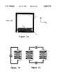
- FIG. 1adepicts a coil according to U.S. Ser. No. 08/313,624;
- FIG. 1bdepicts the equivalent circuit of the coil of FIG. 1a
- FIG. 2adepicts a two-capacitor embodiment of the invention
- FIG. 2bdepicts the equivalent circuit of the coil of FIG. 2a
- FIG. 2cdepicts a variation of the coil of FIG. 2a, without interconnects
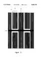
- FIG. 3depicts a four-capacitor embodiment of the invention
- FIG. 4depicts a three-capacitor embodiment of the invention
- FIG. 5depicts an embodiment of the invention having fingerlets
- FIGS. 6a, b and cdepict an embodiment of the invention having tapered conductors
- FIG. 7depicts a simplified two-capacitor coil
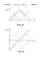
- FIG. 9depicts a simplified one-capacitor coil
- FIGS. 10a,bdepicts the current and voltage distribution of the coil of FIG. 9;
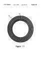
- FIG. 11depicts a single capacitor embodiment of the invention
- FIG. 12depicts a fixture for burn in of the coils prior to trimming
- FIG. 13depicts the equivalent circuit of a burn in fixture with a coil
- FIG. 14depicts the power coupled to the receive loop as a function of frequency for a coil in the burn in fixture.
- FIG. 1adepicts an NMR coil according to Withers et al. It consists of a single loop 10 inductor of greater than one turn with a single interdigital capacitor 12 along one edge. The loop has a length and a width, with squared comers 14. Other embodiments of Withers have a continuous spiral structure or a spiral with crossovers.
- FIG. 1bdepicts the equivalent circuit of the coil of FIG. 1a. Although the RF performance of the coil of FIG. 1a is adequate for some applications, this design has several limitations which the present invention seeks to avoid. First, it is asymmetric in the z direction, and to a lesser extent, in the y direction.
- the superconductoris in the form of a single line except in the capacitor in response to the polarizing magnetic field, DC shielding currents flow in relatively large loops, which introduces large inhomogeneities in the polarizing field in the sample volume.
- the current inventionprovides an advantage over the coil of FIG. 1 by providing structures that minimize magnetic disturbances while improving other properties.
- FIG. 2adepicts a first coil of the invention having greater symmetry than the coil of FIG. 1a, achieved by the use of two capacitors in series.
- FIG. 2ais not drawn to scale but, rather, is drawn so as to better illustrate the features of the invention.
- a superconducting filmforms two sets of elongated, interdigitated conductors 20, 22, forming loops of slightly less than one turn each with a gap 25 between terminals of the conductors.
- a set of conductorsconsists of one or more conductors having their gaps aligned along a common radian of the coil. The gaps of the two sets of coils are symmetrically positioned with respect to the coil's axis. Each loop is rounded at the corners 24 to avoid current crowding.
- the coilis of an essentially uniform width. Adjacent conductors between consecutive gaps around the perimeter of the coil form a capacitor. As used herein, a section of conductor between two gaps is a "finger.” It may readily be seen that for a two-capacitor coil, a loop consists of two fingers 30. Each loop of the coil has a slightly different perimeter from that of adjacent loops to accommodate a nested structure. The RF current flows around the loops. In FIG. 2a, each set of loops is joined at a node 26, 28. As shown in FIG. 2c and discussed below, the nodes are not necessary for a functional coil but their inclusion may improve coil yield. As shown in the equivalent circuit, FIG. 2b, the interdigitated conductors form two capacitors in series. While the coils of FIGS. 2a and 2c do not achieve perfect mirror symmetry about two planes, (that would require four symmetrically-placed capacitors) they are significantly more symmetrical than the coil of FIG. 1a.
- the overall dimensions of the coilare chosen to maximize the filling factor for the sample volume. Suitable inside dimensions for a coil for use with a 5 mm sample tube are 1.7 cm ⁇ 1.2 cm. The number of fingers is then selected with reference to the principles discussed below and to achieve the desired resonant frequency for the probe assembly. In one embodiment having two capacitors, seven loops were used, giving six gaps with 50 ⁇ m gaps between loops.
- each fingeroccupies 1/N of the perimeter of the coil, and each interdigitated conductor consists of one side of two adjacent capacitors with a total length of slightly less than 2/N of the perimeter of the coil. Conductors must be paired to complete loops with gaps separating the capacitive segments. Thus each loop extends over all N capacitors of the coil.
- FIG. 3depicts a coil having four capacitors symmetrically placed.
- Four sets of conductors 32are symmetrically placed around the coil.
- Each conductorhas a length of 1/2 the perimeter of the coil minus the length of the gaps 25 between loops.
- FIG. 4depicts a coil having three sets of conductors 32 with three sets of gaps 25 placed symmetrically around the coil forming three capacitors. It may readily be seen that coils may be designed with any desired number of capacitors.
- the gaps between the fingerlets 42can be minimal (e.g., 10 ⁇ m), as little voltage is developed between the fingerlets, and a short circuit resulting from a photolithographic defect will degrade B 0 uniformity only in proportion to the critical current of the bridging defect.
- the fingerletsmay optionally be joined by a common node 46.
- FIG. 6adepicts a coil in which the interdigital conductors 50 are tapered along their length. The gap, or separation between conductors 52 is kept constant over its entire length.
- FIG. 6bshows an enlarged tip of a single conductor. The tapered conductor 50 is truncated at its tip.
- FIG. 6cshows an enlarged view of a pair of adjacent tapered conductors 50 with the uniform space 52 between conductors. Tapering the electrodes makes optimal use of the current-carrying ability of the superconducting film. Because the current carried by each finger decreases linearly toward its end as current is transferred to the fingers on the other (electrical) side of the capacitor, this approach maintains constant current per unit of film width.
- taperingBy placing the conductor where it is most needed, tapering also reduces the RF resistance of the coil and hence its contribution to system noise. Similarly, the outermost and innermost lines of the capacitors carry only half of the current of the interior capacitors, and need only be one-half the width of the other fingers. Similarly, because of their shorter length, the conductors nearer the center of the coil carry less current than the outer conductors.
- the coil of FIG. 7may be treated as a single-turn inductor with a tuning capacitor which is one-fourth of the total distributed capacitance.
- This coil designmay be viewed as a planar, interdigital version of the coil design used for microscopy and described by Black, et al., "A probe for specimen magnetic resonance microscopy,” Investigative Radiology 27, 157 (1992) and Black et al., "A high-temperature superconducting receiver for nuclear magnetic resonance microscopy,” Science, vol. 259, p. 793, (1993). In fact, this analysis corroborates the design guideline to treat the two capacitors on the two sides of the structure as having simply their lumped value.
- FIG. 7The above analysis was derived in the context of FIG. 7 for interdigital capacitors having only one finger on each electrical side. Clearly, it can be generalized to distributed capacitors of any son (e.g., interdigital, parallel plate) as long as they can be characterized by some capacitance per unit length. For multifinger designs (FIG. 2a), we have assumed that the capacitance per unit length is proportional to the number of neighboring edges on each side of the capacitor (e.g., the design of FIG. 2a has 6 edges in each capacitor).
- FIG. 9shows a modification which can effect a substantial reduction in frequency.
- This designuses, in effect, a single capacitor distributed around a single-turn inductor.
- the equations 1-3apply to this design as well as to that of FIG. 6; however, the boundary conditions are very different.
- the current and voltage distributions in this coilare shown in FIG. 10.
- the single capacitor designcan be extended to more than a single pair of fingers.
- the circular fingers 60are tied to the common node (top) 62 in an alternating fashion from the left and right. The same analysis applies, but using the increased value of capacitance per radian afforded by the multiplicity of fingers.
- the superconducting filmsare high-temperature superconductors which possess low radio-frequency surface resistance at temperatures of 77 K or above. These materials include YBaCuO, TlBaCaCuO, BiSrCaCuO, and related perovskite compounds. Deposition may be by sputtering, laser ablation, evaporation, or chemical vapor deposition.
- the substratemay be sapphire (Al 2 O 3 ), LaAlO 3 , SrTiO 3 , MgO, yttrium stabilized zirconium (YSZ), or other materials or combinations of these substrates with buffer layers.
- the preferred embodiments of the inventionrequire conductive lines as narrow as 10 ⁇ m and an untuned resonant frequency of the coil very near the desired resonant frequency.
- HTShigh-temperature superconducting
- FIG. 12depicts the equivalent circuit of the coil in the burn in apparatus,
- One cable 80is connected to a source of RF power.
- the loop 84 on this "transmit" cableis generally adjusted so that the RF source is strongly coupled to the coil 90.
- the RF sourceis usually an amplifier 100 that is driven by a network analyzer 102.
- the other loop 86is connected to the network analyzer 102 so that the actual current in the coil can be monitored. This "receive" loop is weakly coupled to the coil, so that it does not significantly perturb the power flow into the coil.
- FIG. 14is a plot of the power received from a coil in the burn in apparatus in a 7 Tesla field. The measurement and burn-in process proceeds as follows:
- the RF sourceis set to a low power (typically 0.1 mW), and the transmit and receive loops are adjusted so that the power coupled to the receive loop is no more than 1% of the available power (20 dB or more insertion loss) and the reflected power from the coil at the resonant frequency, f res , is minimized, i.e., the coil is matched to the source, and all available power from the RF source is being dissipated in the coil. This may be repeated at an even lower power to ensure operation in a regime where coil resistance is independent of current. As the RF source frequency is swept through resonance, the power coupled to the receive loop traces the lowermost curve in FIG. 14.
- a low powertypically 0.1 mW
- the coil matched quality factor, Q mis calculated from the full width Df of the resonant line at the 3-dB points from
- Lis the coil inductance.
- the denominatoris the unloaded Q, which is twice the matched Q.
- the available poweris increased until the observed current at resonance reaches the desired burn-in level, which may be 5 to 50 amperes for typical NMR applications. This may require RF powers of 10 W or more for typical coil matched Qs of 10,000 and inductances of 30 nH.
- the RF sourcemay be allowed to dwell at the resonant frequency of the coil for some extended period (seconds) in order to effect burn-in. Alternatively, the RF source may be pulsed to simulate the NMR transmit operation. To most completely simulate the operating environment of the coil, the burn-in process may be conducted with the coil inside a magnet, as in FIG. 14.
- the processis repeated from the beginning, with the resonant frequency and the Q at low power being remeasured. This is done until the coil can withstand the desired level of current without undergoing a frequency shift.
- coil tuning to the desired frequencyis accomplished by techniques such as photolithography, laser trimming, or ultrasonic trimming.
- the coil shown in FIG. 1amay be used as an example.
- the actual remnant frequency fis measured using the RF network-analysis techniques discussed above, with weak inductive coupling to the probe. It is important that the probe be at the temperature at which it will be used for NMR measurements and in a similar electrical environment (e.g., electrical shields are present as in the NMR probe to be used in measurement).
- capacitanceis linear in the amount of edge on either set of electrodes in the interdigital capacitor.
- This removalis accomplished precisely by covering the coil with photoresist and making one or more exposures of the finger area to be removed with light through a rectangular slit of variable length, width, and angular alignment on a microscope. Measurement of the prescribed area to be removed is aided by small tic marks, i.e., a ⁇ ruler ⁇ provided on the pattern at regular intervals along the length of the finger area.
- the resistis developed, and the thin film is etched chemically or in an ion mill.
- a variant of the techniqueis to trim the coil capacitance in situ, i.e., while the resonant frequency is being measured.
- This approachrequires the use of a laser which is focused on the coil and appropriate optics to view the coil during trimming in the low-temperature measurement environment.
- the inventionis equally applicable to low temperature superconductors, and to normal metal conductors at room or low temperature. While low temperature superconductor coils do not offer the advantages of operating temperatures above 20K, they arc capable of achieving the extremely high Q. Normal metal coils do not achieve the high Qs of superconductor coils, but may benefit from application of certain aspects of the invention, and arc at least minimally functional. It will also be appreciated that the coil design may be optimized for filling factor, depending upon the size and shape of the sample, and may be designed for any desired resonant frequency. Further, it will be appreciated that the invention is useful for NMR spectroscopy and microscopy and for magnetic resonance imaging.
Landscapes
- Physics & Mathematics (AREA)
- Condensed Matter Physics & Semiconductors (AREA)
- General Physics & Mathematics (AREA)
- Engineering & Computer Science (AREA)
- Power Engineering (AREA)
- Manufacturing & Machinery (AREA)
- Microelectronics & Electronic Packaging (AREA)
- Magnetic Resonance Imaging Apparatus (AREA)
- Superconductor Devices And Manufacturing Methods Thereof (AREA)
Abstract
Description
dV.sub.o /dφ=dV.sub.i /dφ=-jωLI (1)
dI.sub.o /dφ=-dI.sub.i dφ=-jωC(V.sub.o -V.sub.i) (2)
f.sub.res =(1/2π)(L.sub.T C.sub.T /4).sup.-0.5. (3)
Q.sub.m =f.sub.res /Df
R=(2πf.sub.res L)/(2Q.sub.m)
I=(P/R).sup.0.5
ΔC/C=2(1-f.sub.1 /f.sub.op)
Claims (7)
Priority Applications (12)
| Application Number | Priority Date | Filing Date | Title |
|---|---|---|---|
| US08/461,559US5565778A (en) | 1992-06-01 | 1995-06-05 | Nuclear magnetic resonance probe coil |
| AU62513/96AAU6251396A (en) | 1995-06-05 | 1996-06-03 | Nuclear magnetic resonance probe coil and method of making s ame |
| EP00111914AEP1061378B1 (en) | 1995-06-05 | 1996-06-03 | Method of making a nuclear magnetic resonance probe coil |
| DE69633417TDE69633417T2 (en) | 1995-06-05 | 1996-06-03 | A thin film capacitor for use with an inductor in a nuclear magnetic resonance probe coil |
| EP00111913AEP1061377B1 (en) | 1995-06-05 | 1996-06-03 | Nuclear magnetic resonance probe coil |
| PCT/US1996/008459WO1996039636A1 (en) | 1995-06-05 | 1996-06-03 | Nuclear magnetic resonance probe coil and method of making same |
| DE69615180TDE69615180T2 (en) | 1995-06-05 | 1996-06-03 | PROBE SPOOL FOR THE NUCLEAR MAGNET |
| DE69636756TDE69636756T2 (en) | 1995-06-05 | 1996-06-03 | Probe coil for nuclear magnetic resonance |
| DE69636396TDE69636396T2 (en) | 1995-06-05 | 1996-06-03 | Method for producing a probe coil for nuclear magnetic resonance |
| JP50105797AJP3834758B2 (en) | 1995-06-05 | 1996-06-03 | Coil for nuclear magnetic resonance probe |
| EP96921253AEP0830614B1 (en) | 1995-06-05 | 1996-06-03 | Nuclear magnetic resonance probe coil |
| EP00111912AEP1096266B1 (en) | 1995-06-05 | 1996-06-03 | Thin film capacitor for use with an inductor of a nuclear magnetic resonance probe coil |
Applications Claiming Priority (4)
| Application Number | Priority Date | Filing Date | Title |
|---|---|---|---|
| US07/891,591US5351007A (en) | 1992-06-01 | 1992-06-01 | Superconducting magnetic resonance probe coil |
| US31362494A | 1994-09-27 | 1994-09-27 | |
| US08/409,506US5585723A (en) | 1995-03-23 | 1995-03-23 | Inductively coupled superconducting coil assembly |
| US08/461,559US5565778A (en) | 1992-06-01 | 1995-06-05 | Nuclear magnetic resonance probe coil |
Related Parent Applications (2)
| Application Number | Title | Priority Date | Filing Date |
|---|---|---|---|
| US31362494AContinuation-In-Part | 1992-06-01 | 1994-09-27 | |
| US08/409,506Continuation-In-PartUS5585723A (en) | 1992-06-01 | 1995-03-23 | Inductively coupled superconducting coil assembly |
Publications (1)
| Publication Number | Publication Date |
|---|---|
| US5565778Atrue US5565778A (en) | 1996-10-15 |
Family
ID=23833057
Family Applications (1)
| Application Number | Title | Priority Date | Filing Date |
|---|---|---|---|
| US08/461,559Expired - LifetimeUS5565778A (en) | 1992-06-01 | 1995-06-05 | Nuclear magnetic resonance probe coil |
Country Status (6)
| Country | Link |
|---|---|
| US (1) | US5565778A (en) |
| EP (4) | EP1061378B1 (en) |
| JP (1) | JP3834758B2 (en) |
| AU (1) | AU6251396A (en) |
| DE (4) | DE69636396T2 (en) |
| WO (1) | WO1996039636A1 (en) |
Cited By (41)
| Publication number | Priority date | Publication date | Assignee | Title |
|---|---|---|---|---|
| US5661400A (en)* | 1995-04-07 | 1997-08-26 | Siemens Aktiengesellschaft | Antenna for nuclear magnetic resonance tomography |
| WO1998025163A1 (en)* | 1996-12-02 | 1998-06-11 | The Trustees Of Columbia University In The City Of New York | Multiple resonance superconducting probe |
| US6377047B1 (en) | 2000-06-08 | 2002-04-23 | Varian, Inc. | Superconducting birdcage coils |
| WO2003029834A1 (en)* | 2001-09-28 | 2003-04-10 | Varian, Inc. | Nmr probe with enhanced power handling ability |
| US6556013B2 (en) | 2001-03-09 | 2003-04-29 | Bruker Biospin Corp. | Planar NMR coils with localized field-generating and capacitive elements |
| DE10150131A1 (en)* | 2001-10-11 | 2003-04-30 | Bruker Biospin Ag Faellanden | Superconducting NMR resonators with macroscopically homogeneous distribution of the superconductor |
| US20030151409A1 (en)* | 2002-02-12 | 2003-08-14 | Bruker Biospinag | Normally conducting NMR resonators with macroscopically homogeneous distribution of the conducting material |
| US20030155174A1 (en)* | 2000-03-17 | 2003-08-21 | Peter Mansfield | Active acoustic control in gradient coil design for mri |
| US6727700B2 (en)* | 2001-04-17 | 2004-04-27 | Bruker Biospin Ag | Superconducting NMR resonators generating RF magnetic fields at the sample which are substantially parallel to the plane of a resonator |
| US6751847B1 (en) | 1999-11-04 | 2004-06-22 | Fsu Research Foundation, Inc. | Laser-assisted fabrication of NMR resonators |
| US20040212364A1 (en)* | 2003-04-24 | 2004-10-28 | Hiroshi Morita | Superconductor probe coil for NMR apparatus |
| US20040222186A1 (en)* | 2003-05-09 | 2004-11-11 | Cheng Frederick M.C. | High temperature superconductor tape RF coil for magnetic resonance imaging |
| US20050046420A1 (en)* | 2003-05-06 | 2005-03-03 | Laubacher Daniel B. | Coupled high temperature superconductor coils |
| US20050064657A1 (en)* | 2002-03-28 | 2005-03-24 | Naoyuki Miyazawa | Interdigital capacitor and method for adjusting the same |
| US20050189943A1 (en)* | 1991-06-24 | 2005-09-01 | Hammond Robert B. | Tunable superconducting resonator and methods of tuning thereof |
| US20050231201A1 (en)* | 2004-04-16 | 2005-10-20 | Ge Medical Systems Global Technology Company, Llc | MR imaging method and MRI coil |
| US20050237060A1 (en)* | 2004-04-24 | 2005-10-27 | Bruker Biospin Ag | Radio frequency resonator system with optimized current distribution in the conducting elements |
| US20050253586A1 (en)* | 2002-05-08 | 2005-11-17 | Shigeru Kakugawa | NMR magnet device for solution analysis and NMR apparatus |
| WO2005078468A3 (en)* | 2004-01-20 | 2006-01-19 | Univ Houston System | Superconducting loop, saddle and birdcage mri coils comprising built-in capacitors |
| US20060017440A1 (en)* | 2004-07-23 | 2006-01-26 | Bruker Biospin Ag | Resonator system |
| US20060119357A1 (en)* | 2004-12-03 | 2006-06-08 | Alvarez Robby L | Method for reducing the coupling between excitation and receive coils of a nuclear quadrupole resonance detection system |
| US7061220B1 (en)* | 2004-06-24 | 2006-06-13 | The United States Of America As Represented By The Secretary Of The Army | Passive radio frequency power spectrum analyzer |
| US7176688B2 (en) | 2003-10-22 | 2007-02-13 | Ge Medical Systems Global Technology Company Llc | RF coil and MRI apparatus |
| US20070262777A1 (en)* | 2004-09-16 | 2007-11-15 | Koninklijke Philips Electronics N.V. | Magnetic Resonance Receive Coils with Compact Inductive Components |
| US20080150536A1 (en)* | 2006-12-20 | 2008-06-26 | Varian, Inc. | Cold normal metal and hts nmr probe coils with electric field shields |
| US20090177074A1 (en)* | 2005-05-11 | 2009-07-09 | Audrius Brazdeikis | Intraluminal Multifunctional Sensor System and Method of Use |
| US20090295385A1 (en)* | 2005-05-11 | 2009-12-03 | Audrius Brazdeikis | Magneto Sensor System and Method of Use |
| US20090322323A1 (en)* | 2005-05-11 | 2009-12-31 | Audrius Brazdeikis | Intraluminal Magneto Sensor System and Method of Use |
| EP2151695A2 (en) | 2008-08-07 | 2010-02-10 | Varian, Inc. | NMR probe with two pairs of counter-wound RF spiral coils inducing a reduced external electric field |
| EP2613166A1 (en) | 2012-01-06 | 2013-07-10 | Jeol Resonance Inc. | Superconducting RF coil assembly and method of setting up the same |
| US8564294B2 (en) | 2011-06-28 | 2013-10-22 | Agilent Technologies, Inc. | Nuclear magnetic resonance probe comprising slit superconducting coil with normal-metal overlayer |
| US8779768B2 (en) | 2012-06-12 | 2014-07-15 | The Florida State University Research Foundation, Inc. | NMR RF probe coil exhibiting double resonance |
| US20150323620A1 (en)* | 2014-05-06 | 2015-11-12 | Qed, Llc | Coaxial Cable Magnetic Resonance Image (MRI) Coil |
| DE102017004629A1 (en) | 2016-05-13 | 2017-11-16 | Jeol Ltd. | Magnetic resonance signal detection module |
| US9933501B2 (en) | 2014-08-04 | 2018-04-03 | Quality Electrodynamics, Llc | Magnetic resonance imaging (MRI) coil with integrated decoupling |
| US20190011508A1 (en)* | 2017-07-10 | 2019-01-10 | General Electric Company | Staggered parallel transmission radio frequency coil for magnetic resonance imaging |
| US10739422B2 (en) | 2017-05-16 | 2020-08-11 | Quality Electrodynamics, Llc | Flexible coaxial magnetic resonance imaging (MRI) coil with integrated decoupling |
| US20230041633A1 (en)* | 2021-08-04 | 2023-02-09 | Viewray Technologies, Inc. | Rf coil assemblies |
| US11714146B2 (en) | 2020-09-29 | 2023-08-01 | Socpra Sciences Et Genie S.E.C. | Nuclear magnetic resonance spectrometer, method of operation, and probe therefore |
| US12270873B2 (en) | 2013-03-12 | 2025-04-08 | Viewray Systems, Inc. | Radio frequency transmit coil for magnetic resonance imaging system |
| US12350523B2 (en) | 2021-10-22 | 2025-07-08 | Viewray Systems, Inc. | MRI guided radiotherapy |
Families Citing this family (24)
| Publication number | Priority date | Publication date | Assignee | Title |
|---|---|---|---|---|
| DE19946371C1 (en) | 1999-09-28 | 2001-06-13 | Bruker Ag Faellanden | Connection concept between cryogenic cooling systems and cooled NMR probe heads in an NMR measuring device with cooling system and transfer line |
| US6498487B1 (en)* | 2000-01-25 | 2002-12-24 | Varian, Inc. | Distributed capacitance inserts for NMR probes |
| GB2394191B (en)* | 2000-07-28 | 2005-01-12 | Euroflow | Chromatography methods and chromatography apparatus |
| JP4122833B2 (en) | 2002-05-07 | 2008-07-23 | 株式会社日立製作所 | Probe for NMR apparatus using magnesium diboride |
| US20050104593A1 (en)* | 2003-08-21 | 2005-05-19 | Laubacher Daniel B. | Nuclear quadrupole resonance detection system using a high temperature superconductor self-resonant coil |
| US7295085B2 (en) | 2003-08-21 | 2007-11-13 | E.I. Du Pont De Nemours And Company | Process for making high temperature superconductor devices each having a line oriented in a spiral fashion |
| WO2005081002A2 (en) | 2003-10-23 | 2005-09-01 | E.I Dupont De Nemours And Company | Method for biological identification using high temperature superconductor enhanced nuclear quadrupole resonance |
| US7106058B2 (en) | 2003-11-12 | 2006-09-12 | E.I. Dupont De Nemours And Company | Detection of contraband using nuclear quadrupole resonance |
| US7301344B2 (en) | 2003-11-24 | 2007-11-27 | E.I. Du Pont De Nemours & Co. | Q-damping circuit including a high temperature superconductor coil for damping a high temperature superconductor self-resonant coil in a nuclear quadrupole resonance detection system |
| US20070245374A1 (en) | 2003-11-24 | 2007-10-18 | Inventec Corporation | Video program subtitle tex recording method and system |
| US7332910B2 (en) | 2003-11-24 | 2008-02-19 | E.I. Du Pont De Nemours And Company | Frequency detection system comprising circuitry for adjusting the resonance frequency of a high temperature superconductor self-resonant coil |
| US7375525B2 (en) | 2003-12-15 | 2008-05-20 | E.I. Du Pont De Nemours And Company | Use of multiple sensors in a nuclear quadropole resonance detection system to improve measurement speed |
| WO2005109023A2 (en) | 2004-02-04 | 2005-11-17 | E.I. Dupont De Nemours And Company | Nqr rf coil assembly comprising two or more coils which may be made from hts |
| WO2005078469A1 (en) | 2004-02-04 | 2005-08-25 | E.I. Dupont De Nemours And Company | The use of two or more sensors to detect different nuclear quadrupole resonance signals of a target compound |
| WO2006076004A2 (en)* | 2004-04-15 | 2006-07-20 | E. I. Dupont De Nemours And Company | Decoupling high temperature superconductor sensor arrays in nuclear quadrupole resonance detection systems |
| US7279896B2 (en) | 2004-04-30 | 2007-10-09 | E. I. Du Pont De Nemours And Company | Methods and apparatus for scanning a band of frequencies using an array of high temperature superconductor sensors |
| US7265549B2 (en) | 2004-04-30 | 2007-09-04 | E. I. Du Pont De Nemours And Company | Scanning a band of frequencies using an array of high temperature superconductor sensors tuned to the same frequency |
| US7279897B2 (en) | 2004-04-30 | 2007-10-09 | E. I. Du Pont De Nemours And Company | Scanning a band of frequencies using an array of high temperature superconductor sensors tuned to different frequencies |
| WO2006065929A1 (en) | 2004-12-13 | 2006-06-22 | E. I. Du Pont De Nemours And Company | Metal shield alarm in a nuclear quadrupole resonance/x-ray contraband detection system |
| CN101292175A (en)* | 2005-10-18 | 2008-10-22 | 特西奥普技术有限公司 | Method and apparatus for high-gain magnetic resonance imaging |
| JP2007114209A (en)* | 2006-12-07 | 2007-05-10 | Hitachi Ltd | Nuclear magnetic resonance analyzer for solution |
| JP2008083065A (en)* | 2007-12-04 | 2008-04-10 | Hitachi Ltd | Probe for NMR apparatus using magnesium diboride |
| US8668345B2 (en) | 2011-11-30 | 2014-03-11 | Izi Medical Products | Retro-reflective marker with snap on threaded post |
| KR102276110B1 (en)* | 2019-11-06 | 2021-07-13 | 가천대학교 산학협력단 | RF coil for UHF MRI system |
Citations (7)
| Publication number | Priority date | Publication date | Assignee | Title |
|---|---|---|---|---|
| US4694283A (en)* | 1981-10-30 | 1987-09-15 | Reeb Max E | Identification device in the form of a tag-like strip affixable to an article |
| US5247256A (en)* | 1990-04-25 | 1993-09-21 | Spectrospin Ag | Rf receiver coil arrangement for nmr spectrometers |
| US5258710A (en)* | 1992-03-27 | 1993-11-02 | General Electric Company | Cryogenic probe for NMR microscopy |
| US5276398A (en)* | 1992-06-01 | 1994-01-04 | Conductus, Inc. | Superconducting magnetic resonance probe coil |
| WO1994005022A1 (en)* | 1992-08-25 | 1994-03-03 | Superconductor Technologies, Inc. | Superconducting control elements for rf antennas |
| US5351007A (en)* | 1992-06-01 | 1994-09-27 | Conductus, Inc. | Superconducting magnetic resonance probe coil |
| US5466480A (en)* | 1993-11-12 | 1995-11-14 | University Of Florida | Method for making an NMR coil |
Family Cites Families (5)
| Publication number | Priority date | Publication date | Assignee | Title |
|---|---|---|---|---|
| JPH04500620A (en)* | 1989-07-05 | 1992-02-06 | マックス―プランク―ゲゼルシャフト・ツーア・フェルデルング・デーア・ヴィッセンシャフテン・エー・ファオ | Sample head for nuclear resonance whole body tomography or position-dependent in vivo nuclear resonance spectroscopy |
| JPH03215915A (en)* | 1990-01-19 | 1991-09-20 | Murata Mfg Co Ltd | Laminated capacitor |
| FR2658955B1 (en)* | 1990-02-26 | 1992-04-30 | Commissariat Energie Atomique | COAXIAL RESONATOR WITH DISTRIBUTED TUNING CAPACITY. |
| US5420515A (en)* | 1992-08-28 | 1995-05-30 | Hewlett-Packard Company | Active circuit trimming with AC and DC response trims relative to a known response |
| US5414588A (en)* | 1993-09-20 | 1995-05-09 | The Regents Of The University Of California | High performance capacitors using nano-structure multilayer materials fabrication |
- 1995
- 1995-06-05USUS08/461,559patent/US5565778A/ennot_activeExpired - Lifetime
- 1996
- 1996-06-03DEDE69636396Tpatent/DE69636396T2/ennot_activeExpired - Lifetime
- 1996-06-03EPEP00111914Apatent/EP1061378B1/ennot_activeExpired - Lifetime
- 1996-06-03DEDE69633417Tpatent/DE69633417T2/ennot_activeExpired - Lifetime
- 1996-06-03DEDE69636756Tpatent/DE69636756T2/ennot_activeExpired - Lifetime
- 1996-06-03AUAU62513/96Apatent/AU6251396A/ennot_activeAbandoned
- 1996-06-03EPEP00111913Apatent/EP1061377B1/ennot_activeExpired - Lifetime
- 1996-06-03EPEP00111912Apatent/EP1096266B1/ennot_activeExpired - Lifetime
- 1996-06-03JPJP50105797Apatent/JP3834758B2/ennot_activeExpired - Lifetime
- 1996-06-03DEDE69615180Tpatent/DE69615180T2/ennot_activeExpired - Lifetime
- 1996-06-03WOPCT/US1996/008459patent/WO1996039636A1/enactiveIP Right Grant
- 1996-06-03EPEP96921253Apatent/EP0830614B1/ennot_activeExpired - Lifetime
Patent Citations (7)
| Publication number | Priority date | Publication date | Assignee | Title |
|---|---|---|---|---|
| US4694283A (en)* | 1981-10-30 | 1987-09-15 | Reeb Max E | Identification device in the form of a tag-like strip affixable to an article |
| US5247256A (en)* | 1990-04-25 | 1993-09-21 | Spectrospin Ag | Rf receiver coil arrangement for nmr spectrometers |
| US5258710A (en)* | 1992-03-27 | 1993-11-02 | General Electric Company | Cryogenic probe for NMR microscopy |
| US5276398A (en)* | 1992-06-01 | 1994-01-04 | Conductus, Inc. | Superconducting magnetic resonance probe coil |
| US5351007A (en)* | 1992-06-01 | 1994-09-27 | Conductus, Inc. | Superconducting magnetic resonance probe coil |
| WO1994005022A1 (en)* | 1992-08-25 | 1994-03-03 | Superconductor Technologies, Inc. | Superconducting control elements for rf antennas |
| US5466480A (en)* | 1993-11-12 | 1995-11-14 | University Of Florida | Method for making an NMR coil |
Non-Patent Citations (4)
| Title |
|---|
| Banson, et al., "A probe for specimen magnetic resonance microscopy" (Feb. 1992) Investigative Radiology 27:157-164. |
| Banson, et al., A probe for specimen magnetic resonance microscopy (Feb. 1992) Investigative Radiology 27:157 164.* |
| Black, et al., "A high-temperature superconducting receiver for nuclear magnetic resonance microscopy" (Feb. 5 1993) Science 259:793-795. |
| Black, et al., A high temperature superconducting receiver for nuclear magnetic resonance microscopy (Feb. 5 1993) Science 259:793 795.* |
Cited By (92)
| Publication number | Priority date | Publication date | Assignee | Title |
|---|---|---|---|---|
| US20080032895A1 (en)* | 1991-06-24 | 2008-02-07 | Hammond Robert B | Tunable superconducting resonator and methods of tuning thereof |
| US8030925B2 (en) | 1991-06-24 | 2011-10-04 | Superconductor Technologies, Inc. | Tunable superconducting resonator and methods of tuning thereof |
| US20050189943A1 (en)* | 1991-06-24 | 2005-09-01 | Hammond Robert B. | Tunable superconducting resonator and methods of tuning thereof |
| US7190165B2 (en)* | 1991-06-24 | 2007-03-13 | Superconductor Technologies, Inc. | Tunable superconducting resonator and methods of tuning thereof |
| US5661400A (en)* | 1995-04-07 | 1997-08-26 | Siemens Aktiengesellschaft | Antenna for nuclear magnetic resonance tomography |
| WO1998025163A1 (en)* | 1996-12-02 | 1998-06-11 | The Trustees Of Columbia University In The City Of New York | Multiple resonance superconducting probe |
| US6751847B1 (en) | 1999-11-04 | 2004-06-22 | Fsu Research Foundation, Inc. | Laser-assisted fabrication of NMR resonators |
| US7030610B2 (en)* | 2000-03-17 | 2006-04-18 | Peter Mansfield | Active acoustic control with flexible joints in gradient coil design for MRI |
| US20030155174A1 (en)* | 2000-03-17 | 2003-08-21 | Peter Mansfield | Active acoustic control in gradient coil design for mri |
| US6377047B1 (en) | 2000-06-08 | 2002-04-23 | Varian, Inc. | Superconducting birdcage coils |
| EP1239297A3 (en)* | 2001-03-09 | 2004-12-22 | Bruker Biospin Corp. | Planar NMR coils with localized field-generating and capacitive elements |
| US6842004B2 (en)* | 2001-03-09 | 2005-01-11 | Bruker Biospin Corp. | Planar NMR coils with localized field-generating and capacitive elements |
| US20040032262A1 (en)* | 2001-03-09 | 2004-02-19 | Bruker Biospin Corporation | Planar NMR coils with localized field-generating and capacitive elements |
| US6556013B2 (en) | 2001-03-09 | 2003-04-29 | Bruker Biospin Corp. | Planar NMR coils with localized field-generating and capacitive elements |
| US6727700B2 (en)* | 2001-04-17 | 2004-04-27 | Bruker Biospin Ag | Superconducting NMR resonators generating RF magnetic fields at the sample which are substantially parallel to the plane of a resonator |
| US6590394B2 (en) | 2001-09-28 | 2003-07-08 | Varian, Inc. | NMR probe with enhanced power handling ability |
| WO2003029834A1 (en)* | 2001-09-28 | 2003-04-10 | Varian, Inc. | Nmr probe with enhanced power handling ability |
| DE10150131C2 (en)* | 2001-10-11 | 2003-10-09 | Bruker Biospin Ag Faellanden | RF receiver coil arrangement for an NMR resonator with macroscopically homogeneous distribution of the conductor structures |
| US6605945B2 (en) | 2001-10-11 | 2003-08-12 | Bruker Biospin Ag | Superconducting NMR resonators with macroscopically homogeneous superconductor distribution |
| DE10150131A1 (en)* | 2001-10-11 | 2003-04-30 | Bruker Biospin Ag Faellanden | Superconducting NMR resonators with macroscopically homogeneous distribution of the superconductor |
| US6781377B2 (en)* | 2002-02-12 | 2004-08-24 | Bruker Biospin Ag | Normally conducting NMR resonators with macroscopically homogeneous distribution of the conducting material |
| US20030151409A1 (en)* | 2002-02-12 | 2003-08-14 | Bruker Biospinag | Normally conducting NMR resonators with macroscopically homogeneous distribution of the conducting material |
| US20050064657A1 (en)* | 2002-03-28 | 2005-03-24 | Naoyuki Miyazawa | Interdigital capacitor and method for adjusting the same |
| US7015109B2 (en)* | 2002-03-28 | 2006-03-21 | Fujitsu Quantum Devices Limited | Interdigital capacitor and method for adjusting the same |
| US7053621B2 (en)* | 2002-05-08 | 2006-05-30 | Hitachi, Ltd. | Split type NMR magnet device and NMR apparatus for solution analysis with at least an 11 T static magnetic field and different energizing directions of the NMR magnets |
| US20050253586A1 (en)* | 2002-05-08 | 2005-11-17 | Shigeru Kakugawa | NMR magnet device for solution analysis and NMR apparatus |
| US7292040B2 (en) | 2002-05-08 | 2007-11-06 | Hitachi, Ltd. | Split type NMR superconductive magnet device and NMR apparatus for solution analysis with different current directions and a permanent current switch |
| US7154271B2 (en) | 2002-05-08 | 2006-12-26 | Hitachi, Ltd. | Split type NMR Superconductive magnet device and NMR apparatus for solution analysis with a permanent current switch holding the split type superconducting magnet in a permanent current mode |
| US20060250134A1 (en)* | 2002-05-08 | 2006-11-09 | Shigeru Kakugawa | NMR magnet device for solution analysis and NMR apparatus |
| US20060125478A1 (en)* | 2002-05-08 | 2006-06-15 | Shigeru Kakugawa | NMR magnet device for solution analysis and NMR apparatus |
| US7545143B2 (en) | 2003-04-24 | 2009-06-09 | Hitachi, Ltd. | Superconductor probe coil for NMR apparatus |
| US7218115B2 (en)* | 2003-04-24 | 2007-05-15 | Hitachi, Ltd. | Superconductor probe coil for NMR apparatus |
| US7053619B2 (en)* | 2003-04-24 | 2006-05-30 | Hitachi, Ltd. | Superconductor probe coil for NMR apparatus |
| US20060006868A1 (en)* | 2003-04-24 | 2006-01-12 | Hiroshi Morita | Superconductor probe coil for NMR apparatus |
| US20060132135A1 (en)* | 2003-04-24 | 2006-06-22 | Hiroshi Morita | Superconductor probe coil for NMR apparatus |
| US7295011B2 (en) | 2003-04-24 | 2007-11-13 | Hitachi, Ltd. | Superconductor probe coil for NMR apparatus |
| US20040212364A1 (en)* | 2003-04-24 | 2004-10-28 | Hiroshi Morita | Superconductor probe coil for NMR apparatus |
| US20050046420A1 (en)* | 2003-05-06 | 2005-03-03 | Laubacher Daniel B. | Coupled high temperature superconductor coils |
| US7521932B2 (en)* | 2003-05-06 | 2009-04-21 | The Penn State Research Foundation | Method and system for adjusting the fundamental symmetric mode of coupled high temperature superconductor coils |
| US6943550B2 (en)* | 2003-05-09 | 2005-09-13 | The University Of Hong Kong | High temperature superconductor tape RF coil for magnetic resonance imaging |
| US20040222186A1 (en)* | 2003-05-09 | 2004-11-11 | Cheng Frederick M.C. | High temperature superconductor tape RF coil for magnetic resonance imaging |
| US7176688B2 (en) | 2003-10-22 | 2007-02-13 | Ge Medical Systems Global Technology Company Llc | RF coil and MRI apparatus |
| US7859264B2 (en) | 2004-01-20 | 2010-12-28 | The University Of Houston | Superconducting loop, saddle and birdcage MRI coils capable of simultaneously imaging small nonhuman animals |
| WO2005078468A3 (en)* | 2004-01-20 | 2006-01-19 | Univ Houston System | Superconducting loop, saddle and birdcage mri coils comprising built-in capacitors |
| US8106656B2 (en)* | 2004-01-20 | 2012-01-31 | The University Of Houston System | Superconducting loop, saddle and birdcage MRI coils |
| US20080278166A1 (en)* | 2004-01-20 | 2008-11-13 | Jaroslaw Wosik | Superconducting Loop, Saddle and Birdcage Mri Coils |
| US20110124507A1 (en)* | 2004-01-20 | 2011-05-26 | The University Of Houston System | Superconducting loop, saddle and birdcage mri coils |
| US20050231201A1 (en)* | 2004-04-16 | 2005-10-20 | Ge Medical Systems Global Technology Company, Llc | MR imaging method and MRI coil |
| US7622925B2 (en)* | 2004-04-16 | 2009-11-24 | Ge Medical Systems Global Technology Company, Llc | Parallel MR imaging method with MRI multi-turn coils having different pitch/sensitivity distributions |
| US20050237060A1 (en)* | 2004-04-24 | 2005-10-27 | Bruker Biospin Ag | Radio frequency resonator system with optimized current distribution in the conducting elements |
| US7078902B2 (en) | 2004-04-24 | 2006-07-18 | Bruker Biospin Ag | Radio frequency resonator system with optimized current distribution in the conducting elements |
| US7218090B1 (en)* | 2004-06-24 | 2007-05-15 | The United States Of America As Represented By The Secretary Of The Army. | Passive radio frequency power spectrum analyzer |
| US7061220B1 (en)* | 2004-06-24 | 2006-06-13 | The United States Of America As Represented By The Secretary Of The Army | Passive radio frequency power spectrum analyzer |
| DE102004035851B4 (en)* | 2004-07-23 | 2006-11-16 | Bruker Biospin Ag | Resonator system for generating a high-frequency magnetic field |
| US20060017440A1 (en)* | 2004-07-23 | 2006-01-26 | Bruker Biospin Ag | Resonator system |
| US7193418B2 (en) | 2004-07-23 | 2007-03-20 | Bruker Biospin Ag | Resonator system |
| EP1626286A1 (en) | 2004-07-23 | 2006-02-15 | Bruker BioSpin AG | Superconducting rf resonator system for magnetic resonance |
| DE102004035851A1 (en)* | 2004-07-23 | 2006-03-16 | Bruker Biospin Ag | resonator |
| US7443163B2 (en)* | 2004-09-16 | 2008-10-28 | Koninklijke Philips Electronics N.V. | Magnetic resonance receive coils with compact inductive components |
| US20070262777A1 (en)* | 2004-09-16 | 2007-11-15 | Koninklijke Philips Electronics N.V. | Magnetic Resonance Receive Coils with Compact Inductive Components |
| US7388377B2 (en) | 2004-12-03 | 2008-06-17 | E.I. Du Pont De Nemours And Company | Method for reducing the coupling between excitation and receive coils of a nuclear quadrupole resonance detection system |
| US7710116B2 (en) | 2004-12-03 | 2010-05-04 | The Penn State Research Foundation | Method for reducing the coupling during reception between excitation and receive coils of a nuclear quadrupole resonance detection system |
| US20060119357A1 (en)* | 2004-12-03 | 2006-06-08 | Alvarez Robby L | Method for reducing the coupling between excitation and receive coils of a nuclear quadrupole resonance detection system |
| US20090177074A1 (en)* | 2005-05-11 | 2009-07-09 | Audrius Brazdeikis | Intraluminal Multifunctional Sensor System and Method of Use |
| US20090295385A1 (en)* | 2005-05-11 | 2009-12-03 | Audrius Brazdeikis | Magneto Sensor System and Method of Use |
| US8380279B2 (en) | 2005-05-11 | 2013-02-19 | The University Of Houston System | Intraluminal multifunctional sensor system and method of use |
| US8212554B2 (en) | 2005-05-11 | 2012-07-03 | The University Of Houston System | Intraluminal magneto sensor system and method of use |
| US20090322323A1 (en)* | 2005-05-11 | 2009-12-31 | Audrius Brazdeikis | Intraluminal Magneto Sensor System and Method of Use |
| US20080150536A1 (en)* | 2006-12-20 | 2008-06-26 | Varian, Inc. | Cold normal metal and hts nmr probe coils with electric field shields |
| US7446534B2 (en) | 2006-12-20 | 2008-11-04 | Varian, Inc. | Cold normal metal and HTS NMR probe coils with electric field shields |
| US20100033184A1 (en)* | 2008-08-07 | 2010-02-11 | Withers Richard S | Nmr spiral rf probe coil pair with low external electric field |
| EP2151695A2 (en) | 2008-08-07 | 2010-02-10 | Varian, Inc. | NMR probe with two pairs of counter-wound RF spiral coils inducing a reduced external electric field |
| US7701217B2 (en) | 2008-08-07 | 2010-04-20 | Varian, Inc. | NMR spiral RF probe coil pair with low external electric field |
| US8564294B2 (en) | 2011-06-28 | 2013-10-22 | Agilent Technologies, Inc. | Nuclear magnetic resonance probe comprising slit superconducting coil with normal-metal overlayer |
| EP2613166A1 (en) | 2012-01-06 | 2013-07-10 | Jeol Resonance Inc. | Superconducting RF coil assembly and method of setting up the same |
| JP2013140128A (en)* | 2012-01-06 | 2013-07-18 | Jeol Resonance Inc | Setup method of nmr device |
| US9494663B2 (en) | 2012-01-06 | 2016-11-15 | Jeol Ltd. | NMR spectrometer and method of setting up the same |
| US9274199B2 (en) | 2012-06-12 | 2016-03-01 | The Florida State University Research Foundation, Inc | NMR RF probe coil exhibiting double resonance |
| US8779768B2 (en) | 2012-06-12 | 2014-07-15 | The Florida State University Research Foundation, Inc. | NMR RF probe coil exhibiting double resonance |
| US12270873B2 (en) | 2013-03-12 | 2025-04-08 | Viewray Systems, Inc. | Radio frequency transmit coil for magnetic resonance imaging system |
| US20150323620A1 (en)* | 2014-05-06 | 2015-11-12 | Qed, Llc | Coaxial Cable Magnetic Resonance Image (MRI) Coil |
| US9678180B2 (en)* | 2014-05-06 | 2017-06-13 | Quality Electrodynamics, Llc | Coaxial cable magnetic resonance image (MRI) coil |
| US9933501B2 (en) | 2014-08-04 | 2018-04-03 | Quality Electrodynamics, Llc | Magnetic resonance imaging (MRI) coil with integrated decoupling |
| US10705164B2 (en) | 2016-05-13 | 2020-07-07 | Jeol Ltd. | Magnetic resonance signal detection module |
| DE102017004629A1 (en) | 2016-05-13 | 2017-11-16 | Jeol Ltd. | Magnetic resonance signal detection module |
| US10739422B2 (en) | 2017-05-16 | 2020-08-11 | Quality Electrodynamics, Llc | Flexible coaxial magnetic resonance imaging (MRI) coil with integrated decoupling |
| US20190011508A1 (en)* | 2017-07-10 | 2019-01-10 | General Electric Company | Staggered parallel transmission radio frequency coil for magnetic resonance imaging |
| US10794970B2 (en)* | 2017-07-10 | 2020-10-06 | General Electric Company | Staggered parallel transmission radio frequency coil for magnetic resonance imaging |
| US11714146B2 (en) | 2020-09-29 | 2023-08-01 | Socpra Sciences Et Genie S.E.C. | Nuclear magnetic resonance spectrometer, method of operation, and probe therefore |
| US20230041633A1 (en)* | 2021-08-04 | 2023-02-09 | Viewray Technologies, Inc. | Rf coil assemblies |
| US12025684B2 (en)* | 2021-08-04 | 2024-07-02 | Viewray Systems, Inc. | RF coil assemblies |
| US12350523B2 (en) | 2021-10-22 | 2025-07-08 | Viewray Systems, Inc. | MRI guided radiotherapy |
Also Published As
| Publication number | Publication date |
|---|---|
| DE69615180D1 (en) | 2001-10-18 |
| EP1061378B1 (en) | 2006-07-26 |
| DE69636396T2 (en) | 2007-09-27 |
| JP2000508054A (en) | 2000-06-27 |
| EP1096266B1 (en) | 2004-09-15 |
| DE69633417D1 (en) | 2004-10-21 |
| DE69636756D1 (en) | 2007-01-18 |
| DE69633417T2 (en) | 2005-09-22 |
| EP1096266A1 (en) | 2001-05-02 |
| EP1061377B1 (en) | 2006-12-06 |
| WO1996039636A1 (en) | 1996-12-12 |
| DE69615180T2 (en) | 2002-07-04 |
| EP1061378A1 (en) | 2000-12-20 |
| EP0830614A1 (en) | 1998-03-25 |
| DE69636756T2 (en) | 2007-10-11 |
| AU6251396A (en) | 1996-12-24 |
| DE69636396D1 (en) | 2006-09-07 |
| EP1061377A1 (en) | 2000-12-20 |
| JP3834758B2 (en) | 2006-10-18 |
| EP0830614B1 (en) | 2001-09-12 |
Similar Documents
| Publication | Publication Date | Title |
|---|---|---|
| US5565778A (en) | Nuclear magnetic resonance probe coil | |
| US5619140A (en) | Method of making nuclear magnetic resonance probe coil | |
| US5594342A (en) | Nuclear magnetic resonance probe coil with enhanced current-carrying capability | |
| US5258710A (en) | Cryogenic probe for NMR microscopy | |
| EP0654147B1 (en) | Superconducting magnetic resonance probe coil | |
| Withers et al. | Thin-film HTS probe coils for magnetic-resonance imaging | |
| US5351007A (en) | Superconducting magnetic resonance probe coil | |
| US6121776A (en) | Superconducting hybrid-resonator for receiving NMR-signals | |
| US9274199B2 (en) | NMR RF probe coil exhibiting double resonance | |
| US6768306B2 (en) | Probe for NMR apparatus using magnesium diboride | |
| JP2002341001A (en) | Rf receiving coil device | |
| EP1839066B1 (en) | Nmr rf coils with improved low-frequency efficiency | |
| Ehnholm et al. | NMR studies on nuclear ordering in metallic copper below 1 ΜK | |
| Black et al. | High temperature superconducting resonator for use in nuclear magnetic resonance microscopy | |
| US20240004012A1 (en) | Nmr probehead | |
| Wong et al. | HTS coils for high resolution nuclear magnetic resonance spectroscopy | |
| Lepaisant et al. | Noise current measurements and signal‐to‐noise improvement in low‐temperature, low‐frequency nuclear‐magnetic‐resonance experiments | |
| Thomas | Novel Techniques for High Sensitivity NMR Spectroscopy | |
| JP2013140139A (en) | Nuclear magnetic resonance probe comprising infrared reflection patches | |
| Withers et al. | High-temperature superconductor receiver coils for magnetic-resonance instruments | |
| Withers et al. | HTS Receiver Coils for Magnetic Resonance Instruments |
Legal Events
| Date | Code | Title | Description |
|---|---|---|---|
| AS | Assignment | Owner name:CONDUCTUS, INC., CALIFORNIA Free format text:ASSIGNMENT OF ASSIGNORS INTEREST;ASSIGNORS:BREY, WILLIAM W.;ANDERSON, WESTON A.;WONG, WAI HU;AND OTHERS;REEL/FRAME:007532/0927 Effective date:19950605 | |
| STCF | Information on status: patent grant | Free format text:PATENTED CASE | |
| AS | Assignment | Owner name:VARIAN ASSOCIATES, INC., CALIFORNIA Free format text:ASSIGNMENT OF ASSIGNORS INTEREST;ASSIGNOR:CONDUCTUS, INC.;REEL/FRAME:008650/0763 Effective date:19970731 | |
| AS | Assignment | Owner name:BRUKER INSTRUMENTS, INC., MASSACHUSETTS Free format text:ASSIGNMENT OF PATENT RIGHTS;ASSIGNOR:CONDUCTUS, INC.;REEL/FRAME:008967/0528 Effective date:19970716 | |
| AS | Assignment | Owner name:VARIAN, INC., CALIFORNIA Free format text:ASSIGNMENT OF ASSIGNORS INTEREST;ASSIGNOR:VARIAN ASSOCIATES, INC;REEL/FRAME:009901/0890 Effective date:19990406 | |
| FEPP | Fee payment procedure | Free format text:PAT HLDR NO LONGER CLAIMS SMALL ENT STAT AS SMALL BUSINESS (ORIGINAL EVENT CODE: LSM2); ENTITY STATUS OF PATENT OWNER: LARGE ENTITY | |
| REFU | Refund | Free format text:REFUND - PAYMENT OF MAINTENANCE FEE, 4TH YR, SMALL ENTITY (ORIGINAL EVENT CODE: R283); ENTITY STATUS OF PATENT OWNER: LARGE ENTITY | |
| FEPP | Fee payment procedure | Free format text:PAYER NUMBER DE-ASSIGNED (ORIGINAL EVENT CODE: RMPN); ENTITY STATUS OF PATENT OWNER: LARGE ENTITY Free format text:PAYOR NUMBER ASSIGNED (ORIGINAL EVENT CODE: ASPN); ENTITY STATUS OF PATENT OWNER: LARGE ENTITY | |
| FPAY | Fee payment | Year of fee payment:4 | |
| FEPP | Fee payment procedure | Free format text:PAYER NUMBER DE-ASSIGNED (ORIGINAL EVENT CODE: RMPN); ENTITY STATUS OF PATENT OWNER: LARGE ENTITY Free format text:PAYOR NUMBER ASSIGNED (ORIGINAL EVENT CODE: ASPN); ENTITY STATUS OF PATENT OWNER: LARGE ENTITY | |
| FEPP | Fee payment procedure | Free format text:PAYER NUMBER DE-ASSIGNED (ORIGINAL EVENT CODE: RMPN); ENTITY STATUS OF PATENT OWNER: LARGE ENTITY | |
| FPAY | Fee payment | Year of fee payment:8 | |
| FEPP | Fee payment procedure | Free format text:PAYOR NUMBER ASSIGNED (ORIGINAL EVENT CODE: ASPN); ENTITY STATUS OF PATENT OWNER: LARGE ENTITY | |
| FPAY | Fee payment | Year of fee payment:12 | |
| AS | Assignment | Owner name:AGILENT TECHNOLOGIES, INC., CALIFORNIA Free format text:ASSIGNMENT OF ASSIGNORS INTEREST;ASSIGNOR:VARIAN, INC.;REEL/FRAME:025368/0230 Effective date:20101029 |