US5565759A - Smart battery providing battery life and recharge time prediction - Google Patents
Smart battery providing battery life and recharge time predictionDownload PDFInfo
- Publication number
- US5565759A US5565759AUS08/356,905US35690594AUS5565759AUS 5565759 AUS5565759 AUS 5565759AUS 35690594 AUS35690594 AUS 35690594AUS 5565759 AUS5565759 AUS 5565759A
- Authority
- US
- United States
- Prior art keywords
- battery
- discharge
- temperature
- environmental conditions
- self
- Prior art date
- Legal status (The legal status is an assumption and is not a legal conclusion. Google has not performed a legal analysis and makes no representation as to the accuracy of the status listed.)
- Expired - Lifetime
Links
- 230000007613environmental effectEffects0.000claimsabstractdescription54
- 238000000034methodMethods0.000claimsdescription39
- 230000006870functionEffects0.000claimsdescription33
- 238000007599dischargingMethods0.000claims6
- 238000004891communicationMethods0.000description13
- 238000013461designMethods0.000description10
- 238000010586diagramMethods0.000description10
- 238000005259measurementMethods0.000description10
- 239000000446fuelSubstances0.000description7
- 230000004044responseEffects0.000description6
- 230000007423decreaseEffects0.000description4
- 238000012544monitoring processMethods0.000description4
- 230000009471actionEffects0.000description3
- 230000001413cellular effectEffects0.000description3
- 238000010276constructionMethods0.000description3
- 230000001066destructive effectEffects0.000description3
- 230000000694effectsEffects0.000description3
- 230000008901benefitEffects0.000description2
- 229910052793cadmiumInorganic materials0.000description2
- 230000011664signalingEffects0.000description2
- 238000009987spinningMethods0.000description2
- HBBGRARXTFLTSG-UHFFFAOYSA-NLithium ionChemical compound[Li+]HBBGRARXTFLTSG-UHFFFAOYSA-N0.000description1
- 239000002253acidSubstances0.000description1
- 238000013459approachMethods0.000description1
- 230000005540biological transmissionEffects0.000description1
- OJIJEKBXJYRIBZ-UHFFFAOYSA-Ncadmium nickelChemical compound[Ni].[Cd]OJIJEKBXJYRIBZ-UHFFFAOYSA-N0.000description1
- 230000008859changeEffects0.000description1
- 230000003750conditioning effectEffects0.000description1
- 230000001419dependent effectEffects0.000description1
- 238000005516engineering processMethods0.000description1
- 229910001416lithium ionInorganic materials0.000description1
- 238000004519manufacturing processMethods0.000description1
- 230000007246mechanismEffects0.000description1
- 229910052987metal hydrideInorganic materials0.000description1
- 229910052759nickelInorganic materials0.000description1
- PXHVJJICTQNCMI-UHFFFAOYSA-NnickelSubstances[Ni]PXHVJJICTQNCMI-UHFFFAOYSA-N0.000description1
- -1nickel metal hydrideChemical class0.000description1
- 238000013021overheatingMethods0.000description1
- 230000002035prolonged effectEffects0.000description1
- 230000000717retained effectEffects0.000description1
- 238000005096rolling processMethods0.000description1
- 239000004065semiconductorSubstances0.000description1
- 238000004904shorteningMethods0.000description1
- 230000001960triggered effectEffects0.000description1
Images


Classifications
- H—ELECTRICITY
- H01—ELECTRIC ELEMENTS
- H01M—PROCESSES OR MEANS, e.g. BATTERIES, FOR THE DIRECT CONVERSION OF CHEMICAL ENERGY INTO ELECTRICAL ENERGY
- H01M10/00—Secondary cells; Manufacture thereof
- H01M10/42—Methods or arrangements for servicing or maintenance of secondary cells or secondary half-cells
- H01M10/44—Methods for charging or discharging
- H—ELECTRICITY
- H02—GENERATION; CONVERSION OR DISTRIBUTION OF ELECTRIC POWER
- H02J—CIRCUIT ARRANGEMENTS OR SYSTEMS FOR SUPPLYING OR DISTRIBUTING ELECTRIC POWER; SYSTEMS FOR STORING ELECTRIC ENERGY
- H02J7/00—Circuit arrangements for charging or depolarising batteries or for supplying loads from batteries
- H02J7/00032—Circuit arrangements for charging or depolarising batteries or for supplying loads from batteries characterised by data exchange
- H02J7/00036—Charger exchanging data with battery
- H—ELECTRICITY
- H02—GENERATION; CONVERSION OR DISTRIBUTION OF ELECTRIC POWER
- H02J—CIRCUIT ARRANGEMENTS OR SYSTEMS FOR SUPPLYING OR DISTRIBUTING ELECTRIC POWER; SYSTEMS FOR STORING ELECTRIC ENERGY
- H02J7/00—Circuit arrangements for charging or depolarising batteries or for supplying loads from batteries
- H02J7/00047—Circuit arrangements for charging or depolarising batteries or for supplying loads from batteries with provisions for charging different types of batteries
- H—ELECTRICITY
- H02—GENERATION; CONVERSION OR DISTRIBUTION OF ELECTRIC POWER
- H02J—CIRCUIT ARRANGEMENTS OR SYSTEMS FOR SUPPLYING OR DISTRIBUTING ELECTRIC POWER; SYSTEMS FOR STORING ELECTRIC ENERGY
- H02J7/00—Circuit arrangements for charging or depolarising batteries or for supplying loads from batteries
- H02J7/0047—Circuit arrangements for charging or depolarising batteries or for supplying loads from batteries with monitoring or indicating devices or circuits
- H02J7/0048—Detection of remaining charge capacity or state of charge [SOC]
- H—ELECTRICITY
- H02—GENERATION; CONVERSION OR DISTRIBUTION OF ELECTRIC POWER
- H02J—CIRCUIT ARRANGEMENTS OR SYSTEMS FOR SUPPLYING OR DISTRIBUTING ELECTRIC POWER; SYSTEMS FOR STORING ELECTRIC ENERGY
- H02J7/00—Circuit arrangements for charging or depolarising batteries or for supplying loads from batteries
- H02J7/0047—Circuit arrangements for charging or depolarising batteries or for supplying loads from batteries with monitoring or indicating devices or circuits
- H02J7/005—Detection of state of health [SOH]
- Y—GENERAL TAGGING OF NEW TECHNOLOGICAL DEVELOPMENTS; GENERAL TAGGING OF CROSS-SECTIONAL TECHNOLOGIES SPANNING OVER SEVERAL SECTIONS OF THE IPC; TECHNICAL SUBJECTS COVERED BY FORMER USPC CROSS-REFERENCE ART COLLECTIONS [XRACs] AND DIGESTS
- Y02—TECHNOLOGIES OR APPLICATIONS FOR MITIGATION OR ADAPTATION AGAINST CLIMATE CHANGE
- Y02E—REDUCTION OF GREENHOUSE GAS [GHG] EMISSIONS, RELATED TO ENERGY GENERATION, TRANSMISSION OR DISTRIBUTION
- Y02E60/00—Enabling technologies; Technologies with a potential or indirect contribution to GHG emissions mitigation
- Y02E60/10—Energy storage using batteries
- Y—GENERAL TAGGING OF NEW TECHNOLOGICAL DEVELOPMENTS; GENERAL TAGGING OF CROSS-SECTIONAL TECHNOLOGIES SPANNING OVER SEVERAL SECTIONS OF THE IPC; TECHNICAL SUBJECTS COVERED BY FORMER USPC CROSS-REFERENCE ART COLLECTIONS [XRACs] AND DIGESTS
- Y10—TECHNICAL SUBJECTS COVERED BY FORMER USPC
- Y10S—TECHNICAL SUBJECTS COVERED BY FORMER USPC CROSS-REFERENCE ART COLLECTIONS [XRACs] AND DIGESTS
- Y10S320/00—Electricity: battery or capacitor charging or discharging
- Y10S320/18—Indicator or display
- Y10S320/21—State of charge of battery
Definitions
- patent application 08/357,412entitled “Smart Battery Providing Programmable Remaining Capacity And Run-Time Alarms Based On Battery-Specific Characteristics”
- patent application 08/356,906entitled “Smart Battery Power Availability Feature Based On Battery-Specific Characteristics”
- patent application 08/356,719entitled “Smart Battery. Charger System.”
- the present inventionrelates generally to batteries, and more specifically to rechargeable smart batteries that have electronics for predicting the remaining life and recharge time of the battery based on battery-specific characteristics.
- Rechargeable batteriesare used in many of today's portable electronic devices, such as computers, camcorders, and cellular phones. Typically, these electronic devices are also capable of utilizing AC power. Battery power is utilized when AC power is not convenient or is not available.
- U.S. Pat. No. 5,315,228(the '228 patent) describes a rechargeable battery that measures battery discharge current and estimates battery self-discharge to predict the remaining capacity of the battery (i.e., how full the "tank” is to continue the analogy of the "fuel gauge”).
- Self-dischargerefers to a loss in battery capacity that occurs even when the battery is not supplying any discharge current to a load.
- the '228 patentdescribes self-discharge as being estimated from experimental observations of battery self-discharge.
- Ni--MHnickel metal hydride
- Ni--Cdnickel cadmium
- Both batteriesare estimated to self-discharge at rates of about 1.5% the second six hour period, about 0.78% the third and fourth six hour periods, and approximately 0.39% for each subsequent six hour period.
- self-dischargeis estimated to be about 0.39% for each six hour period.
- FIGS. 1A and 1Billustrate typical self-discharge characteristics as a function of temperature for rechargeable batteries.
- the '228 patent's method for estimating self-dischargecan produce unacceptable errors in the "fitel gauge" remaining capacity indication. Under high temperature conditions, the self-discharge can be much greater than the estimated values.
- one scenariocould include a video camcorder and battery being stored in a car on series of hot, sunny days, causing the battery's "fitel gauge" to erroneously indicate more than enough charge to film a 20-minute wedding ceremony. The scenario concludes with an irate father when his camcorder shuts off 10 minutes into the ceremony, without a spare battery.
- some computer systemsprovide a run-time alarm that indicates when the battery has less than a fixed amount of time remaining at the present discharge rate. In other words, the alarm is triggered if:
- the above-described "fuel gauge”is used to indicate battery capacity for this run-time alarm.
- This type of run-time alarmhas several drawbacks in computer systems.
- the battery capacity provided by the above "fuel gauge”is inaccurate because the dependence of self-discharge on environmental factors, such as temperature, humidity, air pressure, is not considered.
- Chargingis another key aspect of rechargeable batteries.
- Various methods for charging batteriesare known, such as quick charging and trickle charging.
- the general goalis to charge the battery as quickly as possible without damaging the battery. Charging may cause the battery to heat up. Overheating during charging may damage the battery.
- some batteriessuch as Ni--Cd
- one way of avoiding battery damage during chargingis to monitor battery temperature and switch from quick charging to trickle charging if the temperature exceeds a safe level.
- Such effortscan prevent damage to the battery, but do not necessarily optimize the charging of the battery. For example, minimizing charge time while avoiding destructive conditions may optimize recharge time at the expense of reducing the total number of charge/discharge cycles the battery can provide. Thus, the overall useful life of the battery would be reduced.
- Typical battery chargersare designed for use with a specific type of battery.
- a chargermay be designed specifically for charging Ni--Cd batteries, which are charged with a specific construct current, voltage limit, and end-of-charge criteria.
- ongoing improvements to Ni--Cd batteriessuch as changes in battery chemistry or cell design, may require that newer Ni--Cd batteries be optimally charged at a different constant current and/or different voltage limit, not provided by the original charger.
- charging conditionsvary with battery type. For example Ni--MH and Ni--Cd batteries are typically charged at a constant current with a voltage limit. Some lithium-ion and lead-acid batteries are charged at a constant voltage with a current limit.
- Today's battery chargersare not capable of dynamically adapting to meet the various charging needs of different types of batteries, different battery chemistries, and different battery cell designs. Nor are today's battery chargers capable of adapting to meet changing charging needs as battery chemistries and cell designs change over time.
- Another drawback of present battery charging techniquesis that no accurate indication is provided as to how long it will take to fully charge the battery from its present capacity. For example, it would be advantageous to know how long it will take to charge a battery that is presently at half capacity.
- rechargeable batteriessuch as those used in today's electronic equipment such as laptop computer systems, cellular telephones and video cameras, presently pose a number of problems from both the user's and the equipment's perspective.
- theyrepresent an unpredictable source of power.
- equipment powered by the batterycan not determine if the battery, in its present state, is capable of supplying adequate power for an additional load (such as spinning up a hard disk).
- battery chargersmust be individually tailored for use with a specific battery chemistry and cell design and may cause damage if used on another battery with a different chemistry or cell design.
- the present inventioncovers a method and apparatus for predicting the remaining life and recharge time of a battery based on battery-specific characteristics.
- the apparatus of the present inventionpredicts a remaining life of a battery based on a selected discharge rate.
- the apparatusincludes a logic unit and a memory that stores one or more characteristics of the battery and the selected discharge rate.
- the battery characteristicsare a function of one or more environmental conditions of the battery and battery charge or discharge current.
- a remaining capacity value representing the remaining capacity of the batteryis also stored in the memory.
- the logic unitperiodically updates the remaining capacity value based on the battery current, one or more of the environmental conditions, and one or more of the battery characteristics.
- the apparatusfurther includes a means for selecting the discharge rate.
- the logic unitpredicts the remaining life of the battery based on the remaining capacity of the battery and the selected discharge rate.
- a means for indicating the predicted remaining life of the battery to the usermay also be included.
- the apparatus of the present inventionpredicts a recharge time of a battery based on a selected charge rate.
- the apparatusincludes a logic unit and a memory that stores one or more characteristics of the battery and the selected charge rate.
- the battery characteristicsare a function of one or more environmental conditions of the battery and battery charge or discharge current.
- a remaining capacity value representing the remaining capacity of the batteryis also stored in the memory.
- the logic unitperiodically updates the remaining capacity value based on the battery current, one or more of the environmental conditions, and one or more of the battery characteristics.
- the apparatusfurther includes a means for selecting the charge rate.
- the logic unitpredicts the recharge time of the battery based on the remaining capacity of the battery, the selected charge rate, and one or more charging characteristics of the battery.
- FIG. 1Aillustrates an exemplary self-discharge current characteristic as a function of temperature for a rechargeable battery.
- FIG. 1Billustrates another exemplary self-discharge characteristic for a specific battery chemistry showing retained charge as a function of time for various temperatures.
- FIG. 2is a block diagram of one embodiment of a smart battery system.
- FIG. 3is a block diagram of another embodiment of a smart battery system.
- FIG. 4is a block diagram of one embodiment of a smart battery.
- FIG. 5Ais a graph, for a particular cell design and chemistry, of battery cell voltage as a function of discharge rate for various load currents.
- FIG. 5Aillustrates that battery capacity may be dependent on discharge rate.
- FIG. 6is a flowchart of the present invention method for a programmable remaining capacity alarm and programmable remaining run-time alarm.
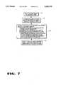
- FIG. 7is a flowchart of the present invention method for indicating whether a battery can provide a desired additional amount of power.
- FIG. 8is a flowchart of the present invention method for predicting the remaining life of a battery based on a user-defined discharge rate.
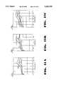
- FIG. 11Ais a graph illustrating the -dV/dt (voltage decrease) at end-of-charge for particular Ni--Cd and Ni--MH batteries.
- FIG. 11Bis a graph illustrating a particular battery's charging characteristic for different temperatures.
- FIG. 11Cis a graph illustrating a particular battery's charging characteristics for different charging currents.
- FIG. 12is a flowchart illustrating the present invention method for predicting the recharge time of a battery.
- a method and apparatus for a smart batterythat can predict the remaining life and recharge time of the battery based on battery-specific characteristics is described.
- numerous specific detailssuch as currents, voltages, temperatures, power, and battery characteristics are set forth in order to provide a thorough understanding of the present invention. It will be apparent, however, to one skilled in the art that the present invention may be practiced without these specific details. In other instances, well-known methods and circuits are shown in block diagram form in order not to obscure the present invention.
- FIG. 2is a block diagram of one embodiment of a smart battery system of the present invention.
- a system host 20, a smart battery charger 22, a smart battery 24, and other SMBus devices 26are coupled to a System Management Bus (SMBus) 28.
- SMBus 28provides communication and signaling between the devices coupled to it.
- Smart battery 24can provide system host 20 and smart battery charger 22 with present capacity and charging information.
- System host 20gets and reports to the user information such as remaining battery capacity, how much battery operating time is left, and whether the battery can provide adequate power for an additional load.
- the systemprovides for optimal charging of smart battery 24.
- SMBus devices 26represent other smart electronic devices that communicate over SMBus 28.
- the back-light controller in a notebook computercan be implemented as smart device and controlled by the system's power management scheme.
- the battery characteristicsmay be stored in the form of tables, formulas, or algorithms that represent the characteristics of the battery.
- Environmental information tracked by smart battery 34may include battery temperature, humidity, air pressure, or other conditions that influence battery performance and/or capacity. Smart battery 34 may also include programmable alarm values for events, such as over-charge, over-voltage, over-temperature, temperature increasing too rapidly, remaining run-time and remaining capacity.
- smart battery 34can accurately determine present battery capacity. Based on the present battery capacity, smart battery 34 can predict remaining battery run-time based on either the present discharge rate or a user-supplied discharge rate. Similarly, smart battery 34 can determine whether an amount of power can be supplied. The amount of power can either be a total amount of power or an amount of power in addition to that already being supplied by the smart battery 34. Similarly, smart battery 34 can also determine its optimal charging voltage and charging current. In summary, based on battery-specific characteristics, measured battery conditions, and present battery capacity, smart battery 34 can accurately determine remaining battery life, power availability, and optimal charging conditions. Smart battery 34 can provide this information to the system host 30 and the smart battery charger 32 to provide users with useful battery information, improve system power management, optimize battery charging, and maximize battery life.
- smart battery 34maintain its own information because batteries, each being unique, are frequently changed in a system.
- a good exampleis a video camcorder where a user may have multiple batteries each with different design capacities, chemistries, and charge states. Even with an accurate state-of-charge indication, a full one AH (ampere hour) battery is not equivalent to a full 1.5 AH battery. Though they both can power the same camcorder, what the user wants to know is whether or not either of these batteries has adequate capacity to record a one-hour event. Smart battery 34 provides the user with accurate remaining capacity information along with an accurate prediction of the remaining operating time.
- System host 30is a piece of electronic equipment powered by smart battery 34.
- system host 30could be a notebook computer, video camera, or cellular phone.
- System host 30can communicate with smart battery 34 via SMBus 38 to request information from smart battery 34.
- System host 30then uses the battery information in the system's power management scheme and/or uses it to provide the user with information about the smart battery's 34 present state and capabilities.
- System host 30also receives critical events from smart battery 34 when smart battery 34 detects a problem. These critical events may include capacity alarm and run-time alarm signals sent to the system host 30. They may also include alarms sent to smart battery charger 32.
- Smart battery charger 32is a battery charger that periodically communicates with smart battery 34 and alters its charging outputs (such as charging voltage and/or current) in response to information provided by smart battery 34. Smart battery charger 32 may be implemented at various levels. A level 1 smart battery charger 32 provides fixed charging outputs that are altered in response to critical alarm messages from the smart battery 34. A level 2 smart battery charger 32 alters the charging voltage and/or charging current in response to charging instructions from smart battery 34 and also responds to critical alarm messages. A level 3 smart battery charger 32 periodically polls smart battery 34 for charging information and may adjust its charging outputs accordingly. A level 3 smart battery charger 32 may also ignore the battery's charging requests and use its own charging algorithum, such as a specific charging pattern. Level 3 smart battery chargers may also respond to critical alarm messages.
- a level 1 smart battery charger 32provides fixed charging outputs that are altered in response to critical alarm messages from the smart battery 34.
- a level 2 smart battery charger 32alters the charging voltage and/or charging current in response to charging instructions from smart battery 34 and also responds to critical alarm
- smart battery charger 32periodically receives information from smart battery 34 indicating how smart battery 34 would like to be charged. Smart battery 34 determines optimal charging conditions based on the smart battery's 34 charging characteristics, present charge level, and environmental conditions. Smart battery charger 32 may adjust its charging voltage and/or charging current in response to the desired charging voltage and desired charging current information received from the smart battery 34.
- smart battery 34can control its own charge cycle to optimize charge time, prolong battery life, and prevent destructive charging conditions. Charging time can be optimized by adjusting charging according to the smart battery's 34 specific charging characteristics. The life of smart battery 34 can be prolonged by avoiding charging conditions that shorten battery life. For example, repeated short discharge/charge cycles or overcharging can shorten battery life. Smart battery 34 may determine that charging is not desirable if present charge capacity is, for example, already above 85%. Smart battery charger 32 can avoid destructive charging conditions by stopping or altering charging when smart battery 34 detects critical events such as: over-charge, over-voltage, over-temperature or temperature increasing too rapidly.
- AC-DC converter 36converts AC power received from AC plug 42 to DC power.
- System power supply 40receives DC power from either smart battery 34 or AC-DC converter 36 and generates a variety of DC voltages for system host 30.
- Vbattrepresents the battery voltage provided between the POSitive and NEGative battery terminals. Many electronic systems require voltages of V cc (typically 5.0 and/or 3.3 volts), +12 volts, and -12 volts.
- the thermistoris a temperature sensor for sensing battery temperature. The temperature sensor may also be used to provide an independent safety mechanism and/or to signal a "default" charging algorithum.
- Communication between system host 30 and smart battery 34can be used to get data for either a user or the system host's 30 power management system.
- the usercan get three types of data from the battery: characteristic data, measured data, and calculated data.
- Characteristic dataincludes battery characteristics, such as pack design voltage, pack design capacity, and charging and capacity characteristics as a function of the battery's environmental conditions.
- Measured datais data that is measured, such as battery temperature.
- Calculated datais data that is determined based on characteristic data and measured data. For example, self-discharge data is determined based on measured environmental conditions and a battery's self-discharge characteristics.
- the smart battery 34has a clock, timer, or other memos for tracking time, the information can be presented as a rolling average over a fixed interval. The clock also allows the battery to periodically track its environment over time.
- Communication between smart battery charger 32 and smart battery 34can be performed: to allow smart battery 34 to be charged as rapidly and as safely as possible, to allow new and different battery chemistries and cell constructions to be used, to allow access to the "correct" charging algorithum for the battery, and to allow smart battery 34 to be charged in a way that maximizes the life of smart battery 34.
- FIG. 4is a block diagram of one embodiment of the smart battery of the present invention.
- Smart battery 82includes rechargeable battery 80 and other electronic circuitry.
- the electronic circuitrymay or may not be physically embedded in the same battery pack as rechargeable battery 80. Wherever located, the electronic circuitry must be able to measure the environmental conditions of the smart battery 82 and contain, or store, the battery-specific characteristics of that smart battery (i.e., the stored battery characteristics must be battery-specific).
- Rechargeable battery 80provides the electrical power of smart battery 82.
- Rechargeable battery 80may include one or more battery cells that are connected in either a series, parallel, or series/parallel combination to form a battery pack.
- ten battery cellseach having a cell voltage of 1.2 volts, can be connected in series such that rechargeable battery 80 provides a voltage of 12.0 volts.
- POS 50 and NEG 52are the positive and negative power terminals, respectively, of smart battery 82 that together provide the voltage V BATT 51.
- DATA 54 and CLOCK 55are data and clock terminals, respectively, that provide a communication interface to the DATA and CLOCK lines, respectively, of SMBus 53.
- Other communication interfacessuch as a single-wire interface, may also be used with the smart battery.
- Non-volatile memory 60stores a capacity alarm value 61, a run-time alarm value 62, a present run-time value 63, a present capacity value 64, one or more self-discharge characteristics 65, one or more charging characteristics 66, one or more discharge characteristics 67, one or more capacity characteristics 68, mode and status bits 69, a user-specified discharge rate 70, and a user-specified charge rate 71.
- battery characteristics 65-68are stored in a ROM memory while alarm values 61-62, run-time and capacity values 63-64, mode and status bits 69, user-specified discharge rate 70, and user-specified charge rate 71 are stored in a non-volatile memory that is both readable and writeable, such as flash or EEPROM memory.
- Microcontroller 56may also include RAM memory.
- Characteristics 65-68may be stored in the form of tables of data, formulas, or algorithum, representing the various battery characteristics.
- Clock 59is a digital timer, counter, or clock that provides logic unit 58 with elapsed time information. Clock 59 can also generate interrupts to cause logic unit 58 to perform actions, such as periodically updating the present capacity value 64.
- A/D converter 72converts analog signals produced by a current measurement circuit 74, a voltage measurement circuit 76, and an environment monitoring circuit 78 into digital form for use by logic unit 58.
- Current measurement circuit 74measures the actual current (charge or discharge) of rechargeable battery 80.
- Current measurement circuit 74receives a voltage, V sense , developed across a small resistor (e.g., 0.01 ⁇ ) that is coupled between the NEG 52 battery terminal and rechargeable battery 80.
- the V sense voltageis directly proportional to a current I sense , which is the actual charge/discharge current of the smart battery 82.
- the current measurement circuit 74generates an analog output voltage proportional to the measured charge/discharge current.
- Current measurement circuit 74provides appropriate scaling of the voltage input to A/D converter 72. Circuits for measuring current are well-known in the art.
- Voltage measurement circuit 76measures the actual terminal voltage of rechargeable battery 80 and produces an analog output proportional to the measured terminal voltage.
- Logic unit 58receives the smart battery's 82 current, voltage, and battery environment information from A/D converter 72 and the battery characteristics from non-volatile memory 60. Based on this information, the logic unit 58 can determine present battery capacity, power availability, predicted run-time, predicted recharge time, and optional charging conditions.
- step 96sending a capacity alarm signal
- step 97sending a run-time alarm signal
- the batteryindicates to the system host whether, or not, the battery can supply the desired amount of power.
- FIG. 9illustrates a smart battery system that includes two smart batteries, smart battery #1 124 and smart battery #2 125.
- a smart battery selector 127connects the smart batteries to either smart battery charger 122, system host 120, or disconnects them, as appropriate.
- Smart battery #1 124is powering the system.
- Smart battery #2 125is being charged by the smart battery charger 122.
- FIG. 10is a block diagram of one embodiment of a smart battery charger of the present invention.
- a smart battery charger 162includes DATA 154 and CLOCK 156 terminals that allow communication with other components of a smart battery system via the DATA and CLOCK lines of the SMBus 153.
- a logic unit 158performs the communication functions of the smart battery charger 162.
- a charging unit 160generates a charging voltage and a charging current at POSitive 150 and NEGative 152 terminals of the smart battery charger 162 in response to a charging current value 164 and a charging voltage value 166 stored in the smart battery charger 162.
- the charging current value 164 and/or the charging voltage value 166may be limits, rather than absolute values.
- the POS 150 and NEG 152 terminalsare connected to the corresponding terminals of the smart battery being charged.
- the charging current value 164 and charging voltage value 166are programmable by other SMBus devices of the system via the SMBus 153.
- logic unit 158programs the values according to commands received via the SMBus 153.
- charging unit 160is not required to output precisely the charging current and charging voltage indicated by the charging current value 164 and charging voltage value 166, respectively.
- the smart batteryis responsible for precisely controlling the charging current and charging voltage. However, reliable operation the charging unit 160 should respond monotonically to increases or decreases in the charging values.
- the charging unit 160includes sensors and feedback circuitry to output precisely the charging current and charging voltage indicated by the charging current value 164 and charging voltage value 166, respectively.
- Smart battery charger 32may be defined in three levels: Level 1, Level 2 and Level 3. Each has a particular set of characteristics and minimum command set. At all levels, the smart battery charger 32 is able to communicate with the smart battery using the SMBus 38. The difference is the ability of the smart battery charger 32 to provide charging services to the smart battery 34. Level 2 chargers support all Level 1 commands. Level 3 chargers support all Level 1 and Level 2 commands.
- a Level 2 smart battery charger 32not only interprets the smart battery's 34 critical warning messages, but is an SMBus slave device that responds to charging voltage and charging current messages sent to it by the smart battery 34 by dynamically adjusting its charging outputs.
- Smart battery 34is in the best position to tell smart battery charger 32 how it can best be charged.
- the charging algorithm in the batterymay simply request a charge condition once or may choose to periodically adjust the smart battery charger's 32 output to meet its present needs.
- the smart battery 34may also send a pattern of charging information for a portion of (e.g., burst or pulse) or a complete charge cycle to smart battery charger 32.
- the Level 2 smart battery charger 32is truly chemistry independent.
- a Level 3 smart battery charger 32not only interprets the smart battery's 34 critical warning messages, but is a SMBus master device. It may poll the smart battery 34 to determine the charging voltage and current the battery desires. The Level 3 charger 32 then dynamically adjusts its output to meet the battery's charging requirements. The smart battery 34 is in the best position to tell the smart battery charger 32 how it wants to be charged. Using the charging algorithm in the battery, the Level 3 charger may simply set a charge condition once or may choose to periodically adjust the charger's 32 output to meet the changing needs of the Smart Battery 34. A Level 3 smart battery charger is free to implement an alternative specialized charging algorithm (e.g.
- a medical devicemay have a stricter temperature limit than the Smart Battery's self-contained charging algorithum, a Level 3 charger could factor in the battery's reported temperature along with the charging current and voltage into its charging algorithm). Like the Level 2 charger, Level 3 smart battery charger is also chemistry independent. A Level 3 smart battery charger may also interrogate the smart battery 34 for other relevant data, such as time remaining to full charge, battery temperature or other data used to control proper charging or discharge conditioning.
- Communication between the smart battery 34 and the smart battery charger 32may be initiated by the battery or the charger depending upon the specific implementation, but the same information is transmitted from the battery to the charger, regardless of which device initiated the transaction. For example, a Level 3 charger may poll the battery periodically to determine the appropriate charge voltage and current, while a Level 2 charger must wait for the battery to initiate the data transmission. In both cases, data is supplied by the battery to the charger. Communications between smart battery 34 and smart battery charger 32 are performed: to allow the smart battery 34 to instruct the smart battery charger 32 to set the appropriate charge current and charge voltage, to allow access to the "correct" charge algorithm for the battery, to allow smart batteries to be charged as rapidly and as safely as possible, and to allow new and different battery technologies to be used.
- FIG. 11Ais a graph illustrating the -dV/dt (voltage decrease) at end-of-charge for typical Ni--Cd and Ni--MH batteries.
- FIG. 1 1Bis an exemplary graph illustrating a battery's charging characteristic for temperatures of 0° C., 20° C., and 45° C. The graph shows that higher temperature decreases the voltage at end-of-charge.
- FIG. 11Cis a graph illustrating a typical battery's charging characteristics for charging currents of 0.1 C, 0.3 C, and 1.0 C. The graph shows that a higher charging current increases the charging voltage.
- the smart batterycan tell a smart battery charger the optimal charging current and charging voltage for charging under any present capacity and environmental conditions of the battery.
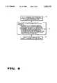
- FIG. 12is a flowchart illustrating the present invention method for predicting the recharge time of a battery.
- the power management system in a computermay provide the following charging options to a user:
- the present invention recharge time prediction methodmay predict a recharge time of 30 minutes based on present battery capacity. The user may also be informed that a Quick Charge has a significantly larger impact on shortening the battery's life than other options. Selecting the "Medium Charge” option may predict a recharge time of 60 minutes. Selecting the "Conserve Battery Life” option may predict a recharge time of 2 hours. If the "Select a Charge Rate” option is selected, the user can enter a custom charge rate. Alternatively, the user can select a custom charge time. Thus, predicted battery recharge time based on user-defined charge rates allows the user to determine the charge rate option that best matches his present needs.
- a charge rateis selected.
- the charge ratemay be selected by a user, a power management system, or by other means.
- a default charge rate(such as the present charge rate) may be selected.
- the system hostqueries the battery for the predicted battery recharge time based on either the present charge conditions or the selected charge rate.
- the methoddetermines the predicted battery recharge time by: 1) measuring the battery's environmental conditions, such as battery temperature, 2) determining present battery capacity, preferably by the method of FIG. 6, and 3) determining the predicted recharge time of the battery based on the measured environmental conditions, the present battery capacity, either the present charge conditions or the selected charge rate, and one or more characteristics of the battery. For example, the charging characteristics of FIG. 11A, FIG. 11B, and FIG. 11C may be used.
- the batteryindicates the predicted battery recharge time to the system host via the SMBus.
Landscapes
- Engineering & Computer Science (AREA)
- Power Engineering (AREA)
- Manufacturing & Machinery (AREA)
- Chemical & Material Sciences (AREA)
- Chemical Kinetics & Catalysis (AREA)
- Electrochemistry (AREA)
- General Chemical & Material Sciences (AREA)
- Health & Medical Sciences (AREA)
- General Health & Medical Sciences (AREA)
- Medical Informatics (AREA)
- Charge And Discharge Circuits For Batteries Or The Like (AREA)
Abstract
Description
This patent application is related to the following patent applications which are assigned to the assignee of the present invention and filed concurrently herewith: patent application 08/357,412, entitled "Smart Battery Providing Programmable Remaining Capacity And Run-Time Alarms Based On Battery-Specific Characteristics", patent application 08/356,906, entitled "Smart Battery Power Availability Feature Based On Battery-Specific Characteristics," and patent application 08/356,719, entitled "Smart Battery. Charger System."
1. Field of the Invention
The present invention relates generally to batteries, and more specifically to rechargeable smart batteries that have electronics for predicting the remaining life and recharge time of the battery based on battery-specific characteristics.
2. Related Art
Rechargeable batteries are used in many of today's portable electronic devices, such as computers, camcorders, and cellular phones. Typically, these electronic devices are also capable of utilizing AC power. Battery power is utilized when AC power is not convenient or is not available.
It is often important to provide accurate information regarding the remaining capacity of the battery. Some batteries provide a "fuel gauge" that gives an indication of the charge level of the battery. For example, U.S. Pat. No. 5,315,228 (the '228 patent) describes a rechargeable battery that measures battery discharge current and estimates battery self-discharge to predict the remaining capacity of the battery (i.e., how full the "tank" is to continue the analogy of the "fuel gauge"). Self-discharge refers to a loss in battery capacity that occurs even when the battery is not supplying any discharge current to a load. The '228 patent describes self-discharge as being estimated from experimental observations of battery self-discharge. For example, in the '228 patent a fully charged Ni--MH (nickel metal hydride) battery is estimated to self-discharge at a rate of approximately 6% the first 6 hours and a Ni--Cd (nickel cadmium) battery is estimated to self-discharge at a rate of 3% the first six hours. Both batteries are estimated to self-discharge at rates of about 1.5% the second six hour period, about 0.78% the third and fourth six hour periods, and approximately 0.39% for each subsequent six hour period. For partially discharged batteries, self-discharge is estimated to be about 0.39% for each six hour period. (See column 12,line 59 --column 14, line 4.)
However, this approach for predicting battery capacity does not account for the dependence of self-discharge or battery capacity on environmental conditions, such as battery temperature. FIGS. 1A and 1B illustrate typical self-discharge characteristics as a function of temperature for rechargeable batteries. In certain situations, the '228 patent's method for estimating self-discharge can produce unacceptable errors in the "fitel gauge" remaining capacity indication. Under high temperature conditions, the self-discharge can be much greater than the estimated values. For example, one scenario could include a video camcorder and battery being stored in a car on series of hot, sunny days, causing the battery's "fitel gauge" to erroneously indicate more than enough charge to film a 20-minute wedding ceremony. The scenario concludes with an irate father when his camcorder shuts off 10 minutes into the ceremony, without a spare battery.
To provide warning of low battery conditions, some computer systems provide a run-time alarm that indicates when the battery has less than a fixed amount of time remaining at the present discharge rate. In other words, the alarm is triggered if:
(estimated battery capacity/present discharge rate)< fixed alarm time. The above-described "fuel gauge" is used to indicate battery capacity for this run-time alarm. This type of run-time alarm has several drawbacks in computer systems. First, the present discharge rate does not adequately reflect the dynamic discharge rates in the computer. For example, in today's laptop and notebook computers, power consumption varies dynamically, on the order of several hundred milliamps (mA). This variation is due to power management systems that turn on and off the hard-disk, LCD screen backlight, CPU, etc., under various conditions to save power. Second, the battery capacity provided by the above "fuel gauge" is inaccurate because the dependence of self-discharge on environmental factors, such as temperature, humidity, air pressure, is not considered. Third, the alarm value is fixed. This removes flexibility from the power management system for adjusting the alarm value to the varying power conditions in the system.
Another drawback of today's rechargeable batteries is they do not provide the systems they power with an indication of whether there is enough power remaining to perform a given task, i.e., the power availability of the battery. Although the above "fuel gauge" provides some indication of a battery's remaining capacity, it does not provide specific information about whether the battery can provide a specified amount of additional power to perform a task. For example, near total discharge, a laptop computer may need to know whether there is sufficient battery power available to spin-up the hard disk to save a file before saving the state of the machine and powering down. What the computer needs to know is whether the battery is capable of providing the power for the additional task without the battery's terminal voltage dropping below a cut-off value.
Yet another drawback of today's rechargeable batteries is that they do not provide an accurate indication of remaining battery life based on a user specified discharge rate. The prior "fuel gauge" gives an estimate of the amount of remaining charge in the battery based on the present discharge rate, but provides no indication regarding how long the battery will continue to provide power at other discharge rates. The battery does not tell the user, and the user cannot ask the battery, how long the battery will continue to supply power if the discharge rate is varied. In addition, neither the above "fuel gauge" nor run-time alarm account for the effect of environmental conditions or large battery loads on battery capacity.
Charging is another key aspect of rechargeable batteries. Various methods for charging batteries are known, such as quick charging and trickle charging. With respect to recharge time, the general goal is to charge the battery as quickly as possible without damaging the battery. Charging may cause the battery to heat up. Overheating during charging may damage the battery. For some batteries, such as Ni--Cd, one way of avoiding battery damage during charging is to monitor battery temperature and switch from quick charging to trickle charging if the temperature exceeds a safe level. Such efforts can prevent damage to the battery, but do not necessarily optimize the charging of the battery. For example, minimizing charge time while avoiding destructive conditions may optimize recharge time at the expense of reducing the total number of charge/discharge cycles the battery can provide. Thus, the overall useful life of the battery would be reduced.
Typical battery chargers are designed for use with a specific type of battery. For example, a charger may be designed specifically for charging Ni--Cd batteries, which are charged with a specific construct current, voltage limit, and end-of-charge criteria. However, ongoing improvements to Ni--Cd batteries, such as changes in battery chemistry or cell design, may require that newer Ni--Cd batteries be optimally charged at a different constant current and/or different voltage limit, not provided by the original charger. In addition, charging conditions vary with battery type. For example Ni--MH and Ni--Cd batteries are typically charged at a constant current with a voltage limit. Some lithium-ion and lead-acid batteries are charged at a constant voltage with a current limit. Today's battery chargers are not capable of dynamically adapting to meet the various charging needs of different types of batteries, different battery chemistries, and different battery cell designs. Nor are today's battery chargers capable of adapting to meet changing charging needs as battery chemistries and cell designs change over time.
Another drawback of present battery charging techniques is that no accurate indication is provided as to how long it will take to fully charge the battery from its present capacity. For example, it would be advantageous to know how long it will take to charge a battery that is presently at half capacity.
In summary, rechargeable batteries, such as those used in today's electronic equipment such as laptop computer systems, cellular telephones and video cameras, presently pose a number of problems from both the user's and the equipment's perspective. First, they represent an unpredictable source of power. Typically a user has little advance knowledge that their battery is about to run out or how much operating time is left. Second, equipment powered by the battery can not determine if the battery, in its present state, is capable of supplying adequate power for an additional load (such as spinning up a hard disk). Third, battery chargers must be individually tailored for use with a specific battery chemistry and cell design and may cause damage if used on another battery with a different chemistry or cell design.
Therefore, a smart battery that can predict the remaining life and recharge time of the battery based on battery-specific characteristics is needed.
The present invention covers a method and apparatus for predicting the remaining life and recharge time of a battery based on battery-specific characteristics.
In one embodiment, the apparatus of the present invention predicts a remaining life of a battery based on a selected discharge rate. The apparatus includes a logic unit and a memory that stores one or more characteristics of the battery and the selected discharge rate. The battery characteristics are a function of one or more environmental conditions of the battery and battery charge or discharge current. A remaining capacity value representing the remaining capacity of the battery is also stored in the memory. The logic unit periodically updates the remaining capacity value based on the battery current, one or more of the environmental conditions, and one or more of the battery characteristics. The apparatus further includes a means for selecting the discharge rate. The logic unit predicts the remaining life of the battery based on the remaining capacity of the battery and the selected discharge rate. A means for indicating the predicted remaining life of the battery to the user may also be included.
In another embodiment, the apparatus of the present invention predicts a recharge time of a battery based on a selected charge rate. The apparatus includes a logic unit and a memory that stores one or more characteristics of the battery and the selected charge rate. The battery characteristics are a function of one or more environmental conditions of the battery and battery charge or discharge current. A remaining capacity value representing the remaining capacity of the battery is also stored in the memory. The logic unit periodically updates the remaining capacity value based on the battery current, one or more of the environmental conditions, and one or more of the battery characteristics. The apparatus further includes a means for selecting the charge rate. The logic unit predicts the recharge time of the battery based on the remaining capacity of the battery, the selected charge rate, and one or more charging characteristics of the battery.
The present invention is illustrated by way of example and not limitation in the figures of the accompanying drawings, in which like references indicate similar elements.
FIG. 1A illustrates an exemplary self-discharge current characteristic as a function of temperature for a rechargeable battery.
FIG. 1B illustrates another exemplary self-discharge characteristic for a specific battery chemistry showing retained charge as a function of time for various temperatures.
FIG. 2 is a block diagram of one embodiment of a smart battery system.
FIG. 3 is a block diagram of another embodiment of a smart battery system.
FIG. 4 is a block diagram of one embodiment of a smart battery.
FIG. 5A is a graph, for a particular cell design and chemistry, of battery cell voltage as a function of discharge rate for various load currents. FIG. 5A illustrates that battery capacity may be dependent on discharge rate.
FIG. 5B is a graph, for a particular cell design and chemistry, of a battery's capacity as a function of temperature for various load currents.
FIG. 6 is a flowchart of the present invention method for a programmable remaining capacity alarm and programmable remaining run-time alarm.
FIG. 7 is a flowchart of the present invention method for indicating whether a battery can provide a desired additional amount of power.
FIG. 8 is a flowchart of the present invention method for predicting the remaining life of a battery based on a user-defined discharge rate.
FIG. 9 is a block diagram of a smart battery system using one or more smart batteries.
FIG. 10 is a block diagram of a smart battery charger.
FIG. 11A is a graph illustrating the -dV/dt (voltage decrease) at end-of-charge for particular Ni--Cd and Ni--MH batteries.
FIG. 11B is a graph illustrating a particular battery's charging characteristic for different temperatures.
FIG. 11C is a graph illustrating a particular battery's charging characteristics for different charging currents.
FIG. 12 is a flowchart illustrating the present invention method for predicting the recharge time of a battery.
A method and apparatus for a smart battery that can predict the remaining life and recharge time of the battery based on battery-specific characteristics is described. In the following description, numerous specific details such as currents, voltages, temperatures, power, and battery characteristics are set forth in order to provide a thorough understanding of the present invention. It will be apparent, however, to one skilled in the art that the present invention may be practiced without these specific details. In other instances, well-known methods and circuits are shown in block diagram form in order not to obscure the present invention.
FIG. 2 is a block diagram of one embodiment of a smart battery system of the present invention. Asystem host 20, asmart battery charger 22, asmart battery 24, andother SMBus devices 26 are coupled to a System Management Bus (SMBus) 28.SMBus 28 provides communication and signaling between the devices coupled to it.Smart battery 24 can providesystem host 20 andsmart battery charger 22 with present capacity and charging information.System host 20 gets and reports to the user information such as remaining battery capacity, how much battery operating time is left, and whether the battery can provide adequate power for an additional load. In addition, the system provides for optimal charging ofsmart battery 24.SMBus devices 26 represent other smart electronic devices that communicate overSMBus 28. For example, the back-light controller in a notebook computer can be implemented as smart device and controlled by the system's power management scheme.
FIG. 3 is a block diagram of another embodiment of asmart battery system 44 of the present invention. A System Management Bus (SMBus) 38 provides communication and signaling between devices according to a defined protocol. In one embodiment, the protocol of the SMBus 38 is based on the I2 C-bus protocol, developed by Philips. I2 C is a two-wire bus protocol designed for data transport between low-speed devices. Asystem host 30, asmart battery charger 32, and a removablesmart battery 34 are coupled to the SMBus 38.
Based on the battery-specific characteristics, measured environmental conditions, measured battery current, and battery history (battery capacity can be affected by the charge/discharge history of the battery),smart battery 34 can accurately determine present battery capacity. Based on the present battery capacity,smart battery 34 can predict remaining battery run-time based on either the present discharge rate or a user-supplied discharge rate. Similarly,smart battery 34 can determine whether an amount of power can be supplied. The amount of power can either be a total amount of power or an amount of power in addition to that already being supplied by thesmart battery 34. Similarly,smart battery 34 can also determine its optimal charging voltage and charging current. In summary, based on battery-specific characteristics, measured battery conditions, and present battery capacity,smart battery 34 can accurately determine remaining battery life, power availability, and optimal charging conditions.Smart battery 34 can provide this information to thesystem host 30 and thesmart battery charger 32 to provide users with useful battery information, improve system power management, optimize battery charging, and maximize battery life.
It is advantageous thatsmart battery 34 maintain its own information because batteries, each being unique, are frequently changed in a system. A good example is a video camcorder where a user may have multiple batteries each with different design capacities, chemistries, and charge states. Even with an accurate state-of-charge indication, a full one AH (ampere hour) battery is not equivalent to a full 1.5 AH battery. Though they both can power the same camcorder, what the user wants to know is whether or not either of these batteries has adequate capacity to record a one-hour event.Smart battery 34 provides the user with accurate remaining capacity information along with an accurate prediction of the remaining operating time.
Another advantage is thatsmart battery 34 provides information for power management and charge control regardless of the particular battery's chemistry or construction.System host 30 can use the battery-specific power information to better manage the power consumption of the system.Smart battery charger 32 can use the battery-specific charging information to optimize the charging ofsmart battery 34.
Thus,smart battery 34 can control its own charge cycle to optimize charge time, prolong battery life, and prevent destructive charging conditions. Charging time can be optimized by adjusting charging according to the smart battery's 34 specific charging characteristics. The life ofsmart battery 34 can be prolonged by avoiding charging conditions that shorten battery life. For example, repeated short discharge/charge cycles or overcharging can shorten battery life.Smart battery 34 may determine that charging is not desirable if present charge capacity is, for example, already above 85%.Smart battery charger 32 can avoid destructive charging conditions by stopping or altering charging whensmart battery 34 detects critical events such as: over-charge, over-voltage, over-temperature or temperature increasing too rapidly.
AC-DC converter 36 converts AC power received from AC plug 42 to DC power.System power supply 40 receives DC power from eithersmart battery 34 or AC-DC converter 36 and generates a variety of DC voltages forsystem host 30. Vbatt represents the battery voltage provided between the POSitive and NEGative battery terminals. Many electronic systems require voltages of Vcc (typically 5.0 and/or 3.3 volts), +12 volts, and -12 volts. The thermistor is a temperature sensor for sensing battery temperature. The temperature sensor may also be used to provide an independent safety mechanism and/or to signal a "default" charging algorithum.
The communication events that can occur within thesmart battery system 44 can be divided into several types, including but not limited to: 1)system host 30 tosmart battery 34, 2)smart battery 34 tosystem host 30, 3)smart battery 34 tosmart battery charger 32, 4)smart battery charger 32 tosmart battery 34, and 5)system host 30 tosmart batter charger 32.
Communication betweensystem host 30 andsmart battery 34 can be used to get data for either a user or the system host's 30 power management system. The user can get three types of data from the battery: characteristic data, measured data, and calculated data. Characteristic data includes battery characteristics, such as pack design voltage, pack design capacity, and charging and capacity characteristics as a function of the battery's environmental conditions. Measured data is data that is measured, such as battery temperature. Calculated data is data that is determined based on characteristic data and measured data. For example, self-discharge data is determined based on measured environmental conditions and a battery's self-discharge characteristics. Additionally, since thesmart battery 34 has a clock, timer, or other memos for tracking time, the information can be presented as a rolling average over a fixed interval. The clock also allows the battery to periodically track its environment over time.
The system host's 30 power management system may query a device driver to determine if an action will cause harm to the system's integrity. For example, spinning up a disk drive at the end of the battery's charge might cause its output voltage to drop below acceptable limits thus causing a system failure. In order to prevent this, the device driver needs information from the battery that will allow it to do the right thing. If the driver queries the battery and discovers that not enough power is available, the driver can request that the power management system turn off a non-critical power use such as the LCD screen back-light and then try again. The driver could also disallow the action and/or request that the user plug in AC power.
In summary, communication betweensystem host 30 andsmart battery 34 may be performed: to allow the user to know the smart battery's 34 remaining life; to tell the user how long it will take to chargesmart battery 34; to allowsmart battery 34 to provide accurate battery information to the user; to determine the system host's 30 real-time power requirements; to enable power management based on "real" information supplied by the battery; to enable battery manufacturers to collect information about a smart battery's 34 usage; and to allow battery manufacturers to electronically "stamp" batteries at time of manufacture.
Communication betweensmart battery charger 32 andsmart battery 34 can be performed: to allowsmart battery 34 to be charged as rapidly and as safely as possible, to allow new and different battery chemistries and cell constructions to be used, to allow access to the "correct" charging algorithum for the battery, and to allowsmart battery 34 to be charged in a way that maximizes the life ofsmart battery 34.
Communication betweensmart battery 34 andsmart battery charger 32 and/orsystem host 30 can be performed: to allowsmart battery 34 to warn other system components of potential problems, to allowsmart battery 34 to warn the user, power management system, or smart battery charger about potentially dangerous situations that the user can rectify, and to allowsmart battery 34 to instruct the smart battery charger what charge current and charge voltage to generate.
FIG. 4 is a block diagram of one embodiment of the smart battery of the present invention.Smart battery 82 includesrechargeable battery 80 and other electronic circuitry. The electronic circuitry may or may not be physically embedded in the same battery pack asrechargeable battery 80. Wherever located, the electronic circuitry must be able to measure the environmental conditions of thesmart battery 82 and contain, or store, the battery-specific characteristics of that smart battery (i.e., the stored battery characteristics must be battery-specific).Rechargeable battery 80 provides the electrical power ofsmart battery 82.Rechargeable battery 80 may include one or more battery cells that are connected in either a series, parallel, or series/parallel combination to form a battery pack. For example, ten battery cells, each having a cell voltage of 1.2 volts, can be connected in series such thatrechargeable battery 80 provides a voltage of 12.0 volts.POS 50 andNEG 52 are the positive and negative power terminals, respectively, ofsmart battery 82 that together provide thevoltage V BATT 51.DATA 54 andCLOCK 55 are data and clock terminals, respectively, that provide a communication interface to the DATA and CLOCK lines, respectively, of SMBus 53. Other communication interfaces, such as a single-wire interface, may also be used with the smart battery.
FIG. 5A is a graph of battery cell voltage as a function of discharge capacity for load currents of 3 C, 1 C, and 0.2 C for a particular battery. The graph illustrates that a higher discharge current reduces the cell voltage. The graph also shows that higher discharge current reduces the capacity of the battery. This is one of the battery characteristics that may be stored innon-volatile memory 60 of FIG. 4. Note that C is a unit indicating battery capacity. By convention, battery capacity is interpreted at a C/5 discharge rate. For example, a battery having a capacity of 2 AH (C) means the battery can provide a current of 400 mA for 5 hours (2 ampere-hours/5 hours).
FIG. 5B is a graph of a particular battery's discharge capacity as a function of temperature for discharge currents of 0.3 C and I C. This battery characteristic illustrates the dependency of battery capacity on temperature and load current.
FIG. 6 is a flowchart of a method for a programmable remaining capacity alarm and programmable remaining rim-time alarm based on battery specific characteristics. Atstep 90, the capacity alarm value and run-time alarm value are set to specified values by the user, the power management system, or by other means. For example, a user may program the capacity alarm value to trigger the remaining capacity alarm when the battery has 10% remaining capacity and program the run-time alarm value to trigger the remaining run-time alarm when the battery is predicted to have a remaining life of 5 minutes. In one embodiment, the alarms are set by writing data to certain locations in the smart battery's memory. In a smart battery system such as that of FIG. 3, the system host can set the alarms of the smart battery via the SMBus.
Atstep 92, a remaining capacity value of the battery is periodically updated by: 1) measuring the battery's environmental conditions, such as battery temperature, 2) measuring actual battery current, 3) determining an incremental self-discharge of the battery (the incremental self-discharge is determined from one or more of the battery's characteristics and the measured environmental conditions of the battery, and 4) changing the remaining capacity value by the incremental self-discharge and the measured battery current. In one embodiment, the incremental self-discharge is based on the battery's self-discharge characteristic and the measured temperature of the battery. In addition, the battery's capacity characteristic can be taken into account when updating the remaining capacity value. The battery's capacity characteristic is an indicator of how the battery's capacity changes with temperature and/or other battery conditions. In particular, the battery's capacity characteristics may be functions of environmental conditions and/or the battery current. The remaining capacity value is an accurate indication of the remaining capacity of the battery.
Atstep 93, the method periodically updates a remaining run-time value based on the remaining capacity value and the present discharge rate of the battery. Thus, the remaining run-time value is a prediction of the remaining battery life based on the present battery capacity, assuming that the present discharge rate remains construct.
Duringstep 94, the method determines whether the remaining capacity value is less than the capacity alarm value. If so, the method proceeds to step 96 where the smart battery sends a capacity alarm signal to the system host, warning of low battery capacity. If not, the method proceeds to step 95.
Atstep 95, the method determines whether the remaining run-time value is less than the run-time alarm value. If so, the method proceeds to step 97 where the smart battery sends a run-time alarm signal to the system host. If not, the method returns to step 92 to again update the remaining capacity value.
After either step 96 (sending a capacity alarm signal) or step 97 (sending a run-time alarm signal), the method jumps back to step 92 to update the remaining capacity value again.
FIG. 7 illustrates a flowchart for the present invention method for determining whether a battery can supply a desired amount of power. Atstep 98, a desired amount of power is selected. Alternatively, an amount of power in addition to that presently provided may be selected (i.e., a desired amount of additional power). Atstep 100, the system host queries the battery whether the battery can supply the desired amount of power. Atstep 102, the battery determines whether it can supply the desired amount of power by: 1) measuring the environmental conditions of the battery, 2) determining the present battery capacity, preferably by the method shown in FIG. 6, 3) measuring the present discharge rate of the battery, and 4) determining whether the battery can supply the desired amount of power according to the measured conditions, present battery capacity, present discharge rate, and one or more characteristics of the battery. For example, the characteristic of FIG. 5 A illustrates the effect of changing the discharge current on the battery capacity. The characteristic of FIG. 5B shows the effect of temperature and battery current on battery capacity.
Atstep 104, the battery indicates to the system host whether, or not, the battery can supply the desired amount of power.
FIG. 8 is a flowchart illustrating the present invention method for predicting the remaining life of a battery based on a selected discharge rate. For example, the power management system in a computer may provide the following options to a user:
______________________________________ User Selects Expected System Discharge Rate ______________________________________ High Performance 1000 mA Medium Performance 700 mA Conserve Power 300 mA Select a Rate <enter rate> ______________________________________
These represent user-selectable performance/power options available to the user. However, what the user may really be interested in is whether the battery will survive his two hour airline flight. The indicated discharge rates for the various performance levels may be determined by a power management system such that they are a reasonably accurate indication of actual discharge. If the user selects the "High Performance" option the present invention battery life prediction method may predict a predicted battery life of 90 minutes. Selecting the "Medium Performance" option may predict a battery life of 2 hours and 5 minutes. Selecting the "Conserve Power" option may indicate a predicted battery life of 5 hours. If the "Select a Rate" option is selected, the user can enter a custom discharge rate and the power management system will attempt to manage the system's power consumption accordingly. Thus, predicted battery life based on user-defined discharge rates allows the user to determine which performance/power option best matches his present needs.
Turning to the present invention battery life prediction method, at step 110 a discharge rate is selected. The discharge rate may be selected by a user, a power management system, or by other means. The system host queries the battery for the estimated remaining life of the battery at the selected discharge rate.
Atstep 112, the method determines the predicted life of the battery by: 1) measuring the battery's environmental conditions, such as battery temperature, 2) determining present battery capacity, preferably by the method of FIG. 6, and 3) determining the predicted remaining life of the battery based on the measured battery conditions, the present battery capacity, the selected discharge rate, and one or more characteristics of the battery. For example, the characteristics of FIG. 5A and FIG. 5B may be used.
Atstep 114, the battery returns the predicted remaining life of the battery to the system host via the SMBus.
FIG. 9 illustrates a smart battery system that includes two smart batteries,smart battery # 1 124 andsmart battery # 2 125. Asmart battery selector 127 connects the smart batteries to eithersmart battery charger 122,system host 120, or disconnects them, as appropriate.Smart battery # 1 124 is powering the system.Smart battery # 2 125 is being charged by thesmart battery charger 122.
FIG. 10 is a block diagram of one embodiment of a smart battery charger of the present invention. Asmart battery charger 162 includesDATA 154 andCLOCK 156 terminals that allow communication with other components of a smart battery system via the DATA and CLOCK lines of the SMBus 153. Alogic unit 158 performs the communication functions of thesmart battery charger 162. A chargingunit 160 generates a charging voltage and a charging current atPOSitive 150 and NEGative 152 terminals of thesmart battery charger 162 in response to a chargingcurrent value 164 and a chargingvoltage value 166 stored in thesmart battery charger 162. The chargingcurrent value 164 and/or the chargingvoltage value 166 may be limits, rather than absolute values. ThePOS 150 andNEG 152 terminals are connected to the corresponding terminals of the smart battery being charged. The chargingcurrent value 164 and chargingvoltage value 166 are programmable by other SMBus devices of the system via the SMBus 153. In other words,logic unit 158 programs the values according to commands received via the SMBus 153. In one embodiment, chargingunit 160 is not required to output precisely the charging current and charging voltage indicated by the chargingcurrent value 164 and chargingvoltage value 166, respectively. In this embodiment, the smart battery is responsible for precisely controlling the charging current and charging voltage. However, reliable operation the chargingunit 160 should respond monotonically to increases or decreases in the charging values. In another embodiment, the chargingunit 160 includes sensors and feedback circuitry to output precisely the charging current and charging voltage indicated by the chargingcurrent value 164 and chargingvoltage value 166, respectively.
Refer now to FIG. 3 to further discuss the operation of a smart battery charger in a smart battery system. The electrical characteristics ofsmart battery charger 32 feature charging characteristics that are controlled by the smart battery itself, in contrast to a charger with fixed charging characteristics that is designed to charge only one particular cell type. The smart battery and smart battery charger combination provide two distinct advantages in system performance and cost. First, charging characteristics are integral to the battery itself, allowing for ideal charging algorithms that match the specific cell types. Each smart battery defines the charging scheme that is best suited to its chemistry, cell construction and capacity. Charging can be tailored to maximize the usable energy at each charge, reduce the charge time, and/or maximize the number of charge cycles. Second, the cost and complexity of the system can be reduced as the charger need only provide the charging voltage and current specified by the Smart Battery, without duplicating the measurement and control electronics already present in the smart battery. For example, in a system where the smart battery indicates the desired charging voltage and charging current to thesmart battery charger 32, thesmart battery charger 32 may not be required to measure or precisely control the voltage and current outputs. In such a feedback system, the smart battery can perform all of the measurement and control functions to cause thesmart battery charger 32 to provide the desired voltage and current. Thesmart battery charger 32 is only required to respond monotonically to the signals from thesmart battery 34.
ALevel 1smart battery charger 32 operates with a fixed charging algorithum and only interprets the smart battery's 34 critical warning messages that indicate that the battery should no longer be charged or discharged. It is not able to adjust its output in response to requests from the smart battery or the system host. TheLevel 1 charger is therefore not chemistry independent and is of limited utility in applications where multiple chemistries are expected. TheLevel 1 charger may use a smart battery's thermistor to determine if a Ni--Cd/Ni--MH or some other type battery chemistry which tolerates a construct current charge is present. When the thermistor is not present or exhibits a very low value (e.g., less than 500Ω), theLevel 1 charger will refuse to output any charge. This is a safety precaution that may be supported by all levels of smart battery chargers.
ALevel 2smart battery charger 32 not only interprets the smart battery's 34 critical warning messages, but is an SMBus slave device that responds to charging voltage and charging current messages sent to it by thesmart battery 34 by dynamically adjusting its charging outputs.Smart battery 34 is in the best position to tellsmart battery charger 32 how it can best be charged. The charging algorithm in the battery may simply request a charge condition once or may choose to periodically adjust the smart battery charger's 32 output to meet its present needs. Thesmart battery 34 may also send a pattern of charging information for a portion of (e.g., burst or pulse) or a complete charge cycle tosmart battery charger 32. TheLevel 2smart battery charger 32 is truly chemistry independent.
A Level 3smart battery charger 32 not only interprets the smart battery's 34 critical warning messages, but is a SMBus master device. It may poll thesmart battery 34 to determine the charging voltage and current the battery desires. The Level 3charger 32 then dynamically adjusts its output to meet the battery's charging requirements. Thesmart battery 34 is in the best position to tell thesmart battery charger 32 how it wants to be charged. Using the charging algorithm in the battery, the Level 3 charger may simply set a charge condition once or may choose to periodically adjust the charger's 32 output to meet the changing needs of theSmart Battery 34. A Level 3 smart battery charger is free to implement an alternative specialized charging algorithm (e.g. a medical device may have a stricter temperature limit than the Smart Battery's self-contained charging algorithum, a Level 3 charger could factor in the battery's reported temperature along with the charging current and voltage into its charging algorithm). Like theLevel 2 charger, Level 3 smart battery charger is also chemistry independent. A Level 3 smart battery charger may also interrogate thesmart battery 34 for other relevant data, such as time remaining to full charge, battery temperature or other data used to control proper charging or discharge conditioning.
Communication between thesmart battery 34 and thesmart battery charger 32 may be initiated by the battery or the charger depending upon the specific implementation, but the same information is transmitted from the battery to the charger, regardless of which device initiated the transaction. For example, a Level 3 charger may poll the battery periodically to determine the appropriate charge voltage and current, while aLevel 2 charger must wait for the battery to initiate the data transmission. In both cases, data is supplied by the battery to the charger. Communications betweensmart battery 34 andsmart battery charger 32 are performed: to allow thesmart battery 34 to instruct thesmart battery charger 32 to set the appropriate charge current and charge voltage, to allow access to the "correct" charge algorithm for the battery, to allow smart batteries to be charged as rapidly and as safely as possible, and to allow new and different battery technologies to be used.
Turning now to battery charging characteristics, FIG. 11A is a graph illustrating the -dV/dt (voltage decrease) at end-of-charge for typical Ni--Cd and Ni--MH batteries. FIG. 1 1B is an exemplary graph illustrating a battery's charging characteristic for temperatures of 0° C., 20° C., and 45° C. The graph shows that higher temperature decreases the voltage at end-of-charge. FIG. 11C is a graph illustrating a typical battery's charging characteristics for charging currents of 0.1 C, 0.3 C, and 1.0 C. The graph shows that a higher charging current increases the charging voltage. Using such charging characteristics, the smart battery can tell a smart battery charger the optimal charging current and charging voltage for charging under any present capacity and environmental conditions of the battery.
FIG. 12 is a flowchart illustrating the present invention method for predicting the recharge time of a battery. For example, the power management system in a computer may provide the following charging options to a user:
______________________________________ User Selects System Uses a Charge Rate of: ______________________________________ Quick Charge 1000 mA Medium Charge 300 mA ConserveBattery Life 100 mA Select a Charge Rate <enter a charge rate> ______________________________________
These represent user-selectable recharge condition options available to the user. However, what the user may really be interested in is whether her battery can be recharged before a critical meeting in 45 minutes. If the user selects the "Quick Charge" option the present invention recharge time prediction method may predict a recharge time of 30 minutes based on present battery capacity. The user may also be informed that a Quick Charge has a significantly larger impact on shortening the battery's life than other options. Selecting the "Medium Charge" option may predict a recharge time of 60 minutes. Selecting the "Conserve Battery Life" option may predict a recharge time of 2 hours. If the "Select a Charge Rate" option is selected, the user can enter a custom charge rate. Alternatively, the user can select a custom charge time. Thus, predicted battery recharge time based on user-defined charge rates allows the user to determine the charge rate option that best matches his present needs.
Turning to the present invention method for predicting the recharge time of a battery, at step 140 a charge rate is selected. The charge rate may be selected by a user, a power management system, or by other means. Alternatively, a default charge rate (such as the present charge rate) may be selected. The system host queries the battery for the predicted battery recharge time based on either the present charge conditions or the selected charge rate.
Atstep 142, the method determines the predicted battery recharge time by: 1) measuring the battery's environmental conditions, such as battery temperature, 2) determining present battery capacity, preferably by the method of FIG. 6, and 3) determining the predicted recharge time of the battery based on the measured environmental conditions, the present battery capacity, either the present charge conditions or the selected charge rate, and one or more characteristics of the battery. For example, the charging characteristics of FIG. 11A, FIG. 11B, and FIG. 11C may be used.
Atstep 144, the battery indicates the predicted battery recharge time to the system host via the SMBus.
Thus, a smart battery that can predict the remaining life and recharge time of the battery based on battery-specific characteristics has been described.
Claims (28)
1. An apparatus for predicting a remaining life of a battery based on a selected discharge rate, the apparatus comprising:
a logic unit;
a memory, coupled to the logic trait, actually storing one or more characteristics of the battery and the selected discharge rate, the battery characteristics being a function of one or more environmental conditions of the battery and/or a battery current;
means, coupled to the memory, for selecting the discharge rate;
a remaining capacity value stored in the memory, the remaining capacity value representing a remaining capacity of the battery;
wherein the logic unit periodically updates the remaining capacity value based on the battery current, one or more of the environmental conditions, and one or more of the battery characteristics; and
wherein the logic unit predicts the remaining life of the battery based on the remaining capacity value and the selected discharge rate.
2. The apparatus of claim 1 further comprising means for indicating the predicted remaining life of the battery.
3. The apparatus of claim 2 wherein the environmental conditions include a temperature of the battery and the battery characteristics include a self-discharge characteristic as a function of the temperature of the battery, and the logic unit updates the remaining capacity value based on the battery current, the self-discharge characteristic, and the temperature of the battery.
4. The apparatus of claim 3 wherein the remaining capacity value is also based on a battery capacity characteristic as a function of the temperature of the battery.
5. The apparatus of claim 2 wherein the environmental conditions include temperature, humidity, and air pressure and the battery characteristics include self-discharge, charging, discharging, and capacity characteristics.
6. An apparatus for indicating a remaining capacity of a battery based on a selected discharge rate, the apparatus comprising:
a logic unit;
a memory, coupled to the logic unit, actually storing one or more characteristics of the battery and the selected discharge rate, the battery characteristics being a function of one or more environmental conditions of the battery and/or a battery current;
an environmental monitor circuit, coupled to the logic unit, for measuring the environmental conditions of the battery;
a current measuring circuit, coupled to the logic unit, for measuring the battery current; and
means, coupled to the memory, for selecting the discharge rate;
a remaining capacity value stored in the memory, the remaining capacity value representing a remaining capacity of the battery;
wherein the logic unit periodically determines an incremental self-discharge of the battery based on the environmental conditions and the battery characteristics and changes the remaining capacity value according to the incremental self-discharge and the battery current; and
wherein the logic unit predicts the remaining battery life of the battery based on the remaining capacity of the battery and the selected discharge rate.
7. The apparatus of claim 6 further comprising means for indicating the predicted remaining life of the battery.
8. The apparatus of claim 7 wherein the environmental conditions include a temperature of the battery and the battery characteristics include a self-discharge characteristic as a function of the temperature of the battery, and the logic unit determines the incremental self-discharge based on the self-charge characteristic and the temperature of the battery.
9. The apparatus of claim 8 wherein the remaining capacity value is also based on a battery capacity characteristic as a function of the temperature of the battery.
10. The apparatus of claim 9 wherein the environmental conditions include temperature, humidity, and air pressure and the battery characteristics include self-discharge, charging, discharging, and capacity characteristics.
11. The apparatus of claim 10 wherein the battery characteristics are stored in the form of either a table or algorithum.
12. A method for predicting a remaining life of a battery based on a selected discharge rate, the method comprising the steps of:
selecting the discharge rate;
determining a present battery capacity based on one or more environmental conditions of the battery and one or more characteristics of the battery, the battery characteristics being functions of the environmental conditions and/or a battery current;
predicting the remaining life of the battery based on the selected discharge rate and the present battery capacity; and
indicating the predicted remaining life of the battery.
13. The method of claim 12 wherein the present battery capacity is based on temperature of the battery, a self-discharge characteristic as a function of temperature, and a battery capacity characteristic as a function of temperature.
14. The method of claim 12 wherein the environmental conditions include temperature, humidity, and air pressure and the battery characteristics include self-discharge, charging, discharging, and capacity characteristics.
15. An apparatus for predicting a recharge time of a battery based on a selected charge rate, the apparatus comprising:
a logic unit;
a memory, coupled to the logic unit, actually storing one or more characteristics of the battery and the selected charge rate, the battery characteristics being a function of one or more environmental conditions of the battery and/or a battery current;
means, coupled to the memory, for selecting the charge rate;
a remaining capacity value stored in the memory, the remaining capacity value representing a remaining capacity of the battery;
wherein the logic unit periodically updates the remaining capacity value based on the battery current, one or more of the environmental conditions, and one or more of the battery characteristics;
wherein the logic unit predicts the recharge time of the battery based on the remaining capacity value, the selected charge rate, and one more charging characteristics of the battery.
16. The apparatus of claim 15 further comprising means for indicating the predicted recharge time of the battery.
17. The apparatus of claim 16 wherein the environmental conditions include a temperature of the battery and the battery characteristics include a self-discharge characteristic as a function of the temperature of the battery, and the logic unit updates the remaining capacity valued based on the battery current, the self-discharge characteristic, and the temperature of the battery.
18. The apparatus of claim 17 wherein the remaining capacity value is also based on a battery capacity characteristic as a function of the temperature of the battery.
19. The apparatus of claim 16 wherein the environmental conditions include temperature, humidity, and air pressure and the battery characteristics include self-discharge, charging, discharging, and capacity characteristics.
20. An apparatus for indicating a recharge time of a battery based on a selected charge rate, the apparatus comprising:
a logic unit;
a memory, coupled to the logic unit, actually storing one or more characteristics of the battery and the selected charge rate, the battery characteristics being a function of one or more environmental conditions of the battery and/or a battery current;
an environmental monitor circuit, coupled to the logic unit, for measuring the environmental conditions of the battery;
a current measuring circuit, coupled to the logic unit, for measuring the battery current; and
means, coupled to the memory, for selecting the charge rate;
a remaining capacity value stored in the memory, the remaining capacity value representing a remaining capacity of the battery;
wherein the logic unit periodically determines an incremental self-discharge of the battery based on the environmental conditions and the battery characteristics and changes the remaining capacity value according to the incremental self-discharge and the battery current; and
wherein the logic unit predicts the recharge time of the battery based on the remaining capacity of the battery, the selected charge rate, and one or more charging characteristics of the battery.
21. The apparatus of claim 20 further comprising means for indicating the predicted recharge time of the battery.
22. The apparatus of claim 21 wherein the environmental conditions include a temperature of the battery and the battery characteristics include a self-discharge characteristic as a function of the temperature of the battery, and the logic unit determines the incremental self-discharge based on the self-discharge characteristic and the temperature of the battery.
23. The apparatus of claim 22 wherein the remaining capacity value is also based on a battery capacity characteristic as a function of the temperature of the battery.
24. The apparatus of claim 20 wherein the environmental conditions include temperature, humidity, and air pressure and the battery characteristics include self-discharge, charging, discharging, and capacity characteristics.
25. The apparatus of claim 23 wherein the battery characteristics are stored in the form of either a table or algorithm.
26. A method for predicting a recharge time of a battery based on a selected charge rate, the method comprising the steps of:
selecting the charge rate;
determining a present battery capacity based on one or more environmental conditions of the battery and one or more characteristics of the battery, the battery characteristics being functions of the environmental conditions and/or a battery current;
predicting the recharge time of the battery based on the selected charge rate, the present battery capacity, and one or more charging characteristics of the battery; and
indicating the predicted remaining life of the battery.
27. The method of claim 26 wherein the present battery capacity is based on temperature of the battery, a self-discharge characteristic as a function of temperature, and a battery capacity characteristic as a function of temperature.
28. The method of claim 26 wherein the environmental conditions include temperature, humidity, and air pressure and the battery characteristics include self-discharge, charging, discharging, and capacity characteristics.
Priority Applications (1)
| Application Number | Priority Date | Filing Date | Title |
|---|---|---|---|
| US08/356,905US5565759A (en) | 1994-12-15 | 1994-12-15 | Smart battery providing battery life and recharge time prediction |
Applications Claiming Priority (1)
| Application Number | Priority Date | Filing Date | Title |
|---|---|---|---|
| US08/356,905US5565759A (en) | 1994-12-15 | 1994-12-15 | Smart battery providing battery life and recharge time prediction |
Publications (1)
| Publication Number | Publication Date |
|---|---|
| US5565759Atrue US5565759A (en) | 1996-10-15 |
Family
ID=23403448
Family Applications (1)
| Application Number | Title | Priority Date | Filing Date |
|---|---|---|---|
| US08/356,905Expired - LifetimeUS5565759A (en) | 1994-12-15 | 1994-12-15 | Smart battery providing battery life and recharge time prediction |
Country Status (1)
| Country | Link |
|---|---|
| US (1) | US5565759A (en) |
Cited By (139)
| Publication number | Priority date | Publication date | Assignee | Title |
|---|---|---|---|---|
| WO1997015839A1 (en)* | 1995-10-27 | 1997-05-01 | Globe-Union, Inc. | Battery monitor and method |
| US5691742A (en)* | 1995-05-24 | 1997-11-25 | Dell U.S.A., L.P. | Software battery gauge for portable computers |
| US5696436A (en)* | 1995-10-27 | 1997-12-09 | Motorola Inc. | Method and system for battery charging |
| US5714870A (en)* | 1996-12-18 | 1998-02-03 | Intel Corporation | Method for measuring suspend-time power consumption in a battery-powered electronic device |
| US5739671A (en)* | 1995-05-15 | 1998-04-14 | Nippondenso Co., Ltd. | Device for accurate detection of remaining discharge capacities of a plurality of batteries |
| US5751134A (en)* | 1996-05-16 | 1998-05-12 | Itronix Corporation | Gas gauging system and method for monitoring battery capacity for battery powered electronic devices |
| US5764027A (en)* | 1996-06-21 | 1998-06-09 | Ford Global Technologies, Inc. | Method and apparatus for battery charge balancing |
| WO1998022830A3 (en)* | 1996-11-21 | 1998-07-23 | Philips Electronics Nv | Battery management system and battery simulator |
| US5872443A (en)* | 1997-02-18 | 1999-02-16 | Williamson; Floyd L. | Electronic method for controlling charged particles to obtain optimum electrokinetic behavior |
| US5903764A (en)* | 1997-05-02 | 1999-05-11 | Micro International, Ltd. | Smart battery selector offering power conversion internally within a portable device |
| US5936534A (en)* | 1997-06-17 | 1999-08-10 | Nec Corporation | Alarm circuit for residual capacity of battery in portable radio transmitting and receiving apparatus |
| US5936385A (en)* | 1995-10-31 | 1999-08-10 | U.S. Philips Corporation | System monitoring the discharging period of the charging/discharging cycles of a rechargeable battery, and host device including a smart battery |
| US5945806A (en)* | 1997-08-29 | 1999-08-31 | Compaq Computer Corporation | Variable-voltage programmable battery module |
| US5955869A (en)* | 1996-07-17 | 1999-09-21 | Rathmann; Roland | Battery pack and a method for monitoring remaining capacity of a battery pack |
| US5986433A (en)* | 1998-10-30 | 1999-11-16 | Ericsson, Inc. | Multi-rate charger with auto reset |
| US6002240A (en)* | 1997-12-12 | 1999-12-14 | Dell Usa, L.P. | Self heating of batteries at low temperatures |
| US6020717A (en)* | 1994-11-08 | 2000-02-01 | Matsushita Electric Industrial Co., Ltd. | Monitoring apparatus for a series assembly of battery modules |
| US6025699A (en)* | 1997-12-12 | 2000-02-15 | Dell Usa, L.P. | Self discharge of batteries at high temperatures |
| US6025695A (en)* | 1997-07-09 | 2000-02-15 | Friel; Daniel D. | Battery operating system |
| US6031302A (en)* | 1997-09-30 | 2000-02-29 | Conexant Systems, Inc. | Battery management system with current measurement across on-resistance of semiconductor cutout switch |
| US6031354A (en)* | 1996-02-01 | 2000-02-29 | Aims Systems, Inc. | On-line battery management and monitoring system and method |
| US6064178A (en)* | 1998-05-07 | 2000-05-16 | Ford Motor Company | Battery charge balancing system having parallel switched energy storage elements |
| US6074775A (en)* | 1998-04-02 | 2000-06-13 | The Procter & Gamble Company | Battery having a built-in controller |
| US6118248A (en)* | 1998-04-02 | 2000-09-12 | The Procter & Gamble Company | Battery having a built-in controller to extend battery service run time |
| US6163131A (en)* | 1998-04-02 | 2000-12-19 | The Procter & Gamble Company | Battery having a built-in controller |
| US6163132A (en)* | 1997-12-29 | 2000-12-19 | Sony Corporation | Battery charging status indicator apparatus |
| WO2000065705A3 (en)* | 1999-04-23 | 2001-02-08 | Qualcomm Inc | System and method for accurately determining remaining battery life |
| US6194870B1 (en) | 1998-10-09 | 2001-02-27 | Samsung Electronics Co., Ltd. | System for automatically indicating that battery should be replaced and method thereof |
| US6198250B1 (en) | 1998-04-02 | 2001-03-06 | The Procter & Gamble Company | Primary battery having a built-in controller to extend battery run time |
| US6218806B1 (en) | 1998-06-03 | 2001-04-17 | Black & Decker Inc. | Method and apparatus for obtaining product use information |
| US6403251B1 (en)* | 2000-01-31 | 2002-06-11 | Moltech Power Systems, Inc | Battery pack with multiple secure modules |
| US6449726B1 (en) | 1999-07-21 | 2002-09-10 | Spotware Technologies, Inc. | Method, system, software, and signal for estimating battery life in a remote control device |
| US20020161537A1 (en)* | 2001-04-27 | 2002-10-31 | International Business Machines Corporation | Method and apparatus for determining battery life |
| JP2002320341A (en)* | 2001-02-14 | 2002-10-31 | Sony Corp | Charge/discharge device and method therefor, power supply device and method therefor, power supply system and method therefor, program storage medium, and program thereof |
| US6483275B1 (en) | 1999-04-23 | 2002-11-19 | The Board Of Trustees Of The Univesity Of Illinois | Consumer battery having a built-in indicator |
| US6532425B1 (en)* | 1998-09-18 | 2003-03-11 | C&D Charter Holdings, Inc. | Remote battery plant monitoring system |
| US20030188204A1 (en)* | 2001-02-14 | 2003-10-02 | Kei Tashiro | Charging/discharging apparatus and method, power supplying apparatus and method, power supplying system and method, program storage medium, and program |
| US20030221132A1 (en)* | 2002-05-22 | 2003-11-27 | Dell Products L.P. | System, method, and computer program product for using a legacy battery in an information handling system |
| US20040012396A1 (en)* | 2001-04-06 | 2004-01-22 | Microchip Technology Incorporated | Battery cover assembly having integrated battery condition monitoring |
| EP1324062A3 (en)* | 2001-12-14 | 2004-02-11 | VB Autobatterie GmbH | Method for determining the operating state of a storage battery |
| US6750656B2 (en) | 2002-09-10 | 2004-06-15 | Telefonaktiebolaget Lm Ericsson(Publ) | Estimation of current consumption due to radio activities in GPRS |
| US20040155661A1 (en)* | 2003-02-07 | 2004-08-12 | Field Robert B | Method and system for modeling energy transfer |
| US20040212342A1 (en)* | 2001-04-06 | 2004-10-28 | Microchip Technology Incorporated | Battery cover assembly having integrated battery condition monitoring |
| WO2004092758A1 (en)* | 2003-04-16 | 2004-10-28 | Robert Bosch Gmbh | Method and device for predicting the starting capacity of a vehicle |
| US20040232884A1 (en)* | 2001-05-25 | 2004-11-25 | Jean-Pierre Vaillancourt | Self-diagnosis system for an energy storage device |
| US6835491B2 (en) | 1998-04-02 | 2004-12-28 | The Board Of Trustees Of The University Of Illinois | Battery having a built-in controller |
| US20050001590A1 (en)* | 2003-04-29 | 2005-01-06 | Research In Motion Limited | Multiple function current-sharing charging system and method |
| US20050027465A1 (en)* | 2003-07-29 | 2005-02-03 | Pozsgay Brian T. | Method for estimating time to full-charge in a rechargeable battery |
| US20050134230A1 (en)* | 2003-11-14 | 2005-06-23 | Hideyuki Sato | Battery pack, battery protection processsing apparatus, and control method of the battery protection processing apparatus |
| US20050177780A1 (en)* | 2004-01-23 | 2005-08-11 | An-Sheng Chang | Powered interface card and method of providing backup power supply |
| US20050189819A1 (en)* | 2004-03-01 | 2005-09-01 | Arif Maskatia | Power supply system for supplying power to an electronic apparatus |
| RU2265921C2 (en)* | 2003-12-05 | 2005-12-10 | Государственное образовательное учреждение высшего профессионального образования Южно-Российский государственный технический университет (Новочеркасский политехнический институт) | System for diagnosing lead storage batteries |
| US20060122799A1 (en)* | 2004-10-01 | 2006-06-08 | Yi-Chang Chen | Method and device for clock calibration |
| US20060255770A1 (en)* | 2005-04-06 | 2006-11-16 | Jacques Rocher | Method for controlling the life of a battery and corresponding device |
| US20060261816A1 (en)* | 2005-05-20 | 2006-11-23 | Jacques Rocher | Method of diagnosis of a state of end of life of a determined type of battery |
| US20070063675A1 (en)* | 2005-09-19 | 2007-03-22 | Walline Erin K | Method and system for providing battery usable life information to users of information handling systems |
| WO2007050155A1 (en)* | 2005-10-27 | 2007-05-03 | Hewlett-Packard Development Company, L.P. | Battery analysis system and method |
| WO2007048366A1 (en)* | 2005-10-28 | 2007-05-03 | Temic Automotive Electric Motors Gmbh | Method and device for controlling the operating point of a battery |
| US20070139008A1 (en)* | 2005-12-15 | 2007-06-21 | Sterz Stephen D | Method and system for charge rate adjustment to enhance battery cycle life |
| CN100342304C (en)* | 2005-01-20 | 2007-10-10 | 英业达股份有限公司 | Charging management method and system |
| US20070252552A1 (en)* | 2006-04-27 | 2007-11-01 | Walrath Craig A | Power management system and method |
| JP2007325499A (en)* | 2001-02-14 | 2007-12-13 | Sony Corp | Charger/discharger and charging/discharging method, power supply device and method, power supply system and method, program storage medium, and program |
| JP2007325498A (en)* | 2001-02-14 | 2007-12-13 | Sony Corp | Charger/discharger and charging/discharging method, power supply device and method, power supply system and method, program storage medium, and program |
| JP2007325500A (en)* | 2001-02-14 | 2007-12-13 | Sony Corp | Charger/discharger and charging/discharging method, power supply device and method, power supply system and method, program storage medium, and program |
| US20080005593A1 (en)* | 2006-06-29 | 2008-01-03 | David Anthony Wyatt | Managing wasted active power in processors |
| US20080005474A1 (en)* | 2006-06-29 | 2008-01-03 | Matthew Long | Controlling memory parameters |
| US20080178032A1 (en)* | 2007-01-24 | 2008-07-24 | Walrath Craig A | Power management system and method |
| US20080208535A1 (en)* | 2007-02-23 | 2008-08-28 | Nec Corporation | Disc array device |
| US20090163820A1 (en)* | 2006-05-25 | 2009-06-25 | Koninklijke Philips Electronics N. V. | Cordless charger for a wearable patient monitor |
| US20090220921A1 (en)* | 2008-03-03 | 2009-09-03 | Sonitus Medical, Inc. | Systems and methods to provide communication and monitoring of user status |
| US20090243553A1 (en)* | 2008-03-25 | 2009-10-01 | John Walley | Method and system for power and charging control in a bluetooth headset |
| US20090276015A1 (en)* | 2008-04-30 | 2009-11-05 | Medtronic, Inc. | Time to next recharge session feedback while recharging an implantable medical device, system and method therefore |
| US20090289601A1 (en)* | 2008-05-23 | 2009-11-26 | Qualcomm Incorporated | Method and apparatus for system acquisition while maintaining a defined battery life span |
| US7664277B2 (en) | 2006-05-30 | 2010-02-16 | Sonitus Medical, Inc. | Bone conduction hearing aid devices and methods |
| US7682303B2 (en) | 2007-10-02 | 2010-03-23 | Sonitus Medical, Inc. | Methods and apparatus for transmitting vibrations |
| US20100133006A1 (en)* | 2008-12-01 | 2010-06-03 | Schlumberger Technology Corporation | Downhole communication devices and methods of use |
| WO2010068313A1 (en)* | 2008-12-12 | 2010-06-17 | Sony Ericsson Mobile Communications Ab | Intelligent battery warning system |
| US20100175922A1 (en)* | 2009-01-15 | 2010-07-15 | Schlumberger Technology Corporation | Directional drilling control devices and methods |
| US7782020B1 (en)* | 2005-01-14 | 2010-08-24 | Network Appliance, Inc. | Operating a non-volatile memory charger |
| US20100229018A1 (en)* | 2009-03-09 | 2010-09-09 | International Business Machines Corporation | Three stage power up in computer storage system |
| US7888913B1 (en) | 2009-09-08 | 2011-02-15 | Intermec Ip Corp. | Smart battery charger |
| US7945068B2 (en) | 2008-03-04 | 2011-05-17 | Sonitus Medical, Inc. | Dental bone conduction hearing appliance |
| US7974845B2 (en) | 2008-02-15 | 2011-07-05 | Sonitus Medical, Inc. | Stuttering treatment methods and apparatus |
| US20110193518A1 (en)* | 2010-02-10 | 2011-08-11 | James Wright | Battery override |
| US8150075B2 (en) | 2008-03-04 | 2012-04-03 | Sonitus Medical, Inc. | Dental bone conduction hearing appliance |
| US8224013B2 (en) | 2007-08-27 | 2012-07-17 | Sonitus Medical, Inc. | Headset systems and methods |
| US20120191578A1 (en)* | 2011-01-26 | 2012-07-26 | Makoto Katagishi | Storage battery managing system, and recycle equipment and management server to be applied therein |
| US8270637B2 (en) | 2008-02-15 | 2012-09-18 | Sonitus Medical, Inc. | Headset systems and methods |
| US8270638B2 (en) | 2007-05-29 | 2012-09-18 | Sonitus Medical, Inc. | Systems and methods to provide communication, positioning and monitoring of user status |
| US8291912B2 (en) | 2006-08-22 | 2012-10-23 | Sonitus Medical, Inc. | Systems for manufacturing oral-based hearing aid appliances |
| US8319479B2 (en) | 2010-03-23 | 2012-11-27 | Ememory Technology Inc. | Method of estimating battery recharge time and related device |
| CN102902339A (en)* | 2011-07-28 | 2013-01-30 | 广达电脑股份有限公司 | Server cabinet system |
| CN102902340A (en)* | 2011-07-28 | 2013-01-30 | 广达电脑股份有限公司 | Server cabinet system and control method thereof |
| US20130031382A1 (en)* | 2011-07-28 | 2013-01-31 | Quanta Computer Inc. | Rack server system and operation method applicable thereto |
| US8433080B2 (en) | 2007-08-22 | 2013-04-30 | Sonitus Medical, Inc. | Bone conduction hearing device with open-ear microphone |
| CN103227350A (en)* | 2013-04-17 | 2013-07-31 | 深圳市科曼医疗设备有限公司 | Intelligent battery management system and method for medical equipment |
| US20130226486A1 (en)* | 2012-01-19 | 2013-08-29 | Nike, Inc. | Power Management in an Activity Monitoring Device |
| US20130249521A1 (en)* | 2012-03-26 | 2013-09-26 | Chao-Kuo Cheng | Method for performing power consumption control, and associated apparatus |
| CN103455126A (en)* | 2013-09-16 | 2013-12-18 | 贝壳网际(北京)安全技术有限公司 | Method and client device for determining residual service life of battery and mobile terminal |
| US20140042986A1 (en)* | 2012-08-08 | 2014-02-13 | Simplo Technology Company, Ltd. | Charging control method of a rechargeable battery |
| US20140167680A1 (en)* | 2012-12-18 | 2014-06-19 | Hyundai Motor Company | System and method for periodically charging sub-battery for electric vehicle |
| US8795172B2 (en) | 2007-12-07 | 2014-08-05 | Sonitus Medical, Inc. | Systems and methods to provide two-way communications |
| US20140217989A1 (en)* | 2011-09-02 | 2014-08-07 | Nec Corporation | Battery control system, battery controller, battery control method, and recording medium |
| US20140303507A1 (en)* | 2003-12-17 | 2014-10-09 | Physio-Control, Inc. | External defibrillator with power and battery sharing capabilities with a pod |
| JP2014236582A (en)* | 2013-05-31 | 2014-12-15 | 三菱自動車工業株式会社 | Charging system, and charging method |
| US20150000651A1 (en)* | 2012-01-16 | 2015-01-01 | Honeywell International Inc. | Accurate determination of remaining time to battery empty in a powered air purifying respirator |
| DE102014109210A1 (en)* | 2014-07-01 | 2016-01-07 | Jungheinrich Aktiengesellschaft | Charger for charging a battery |
| EP2820432A4 (en)* | 2012-03-01 | 2016-01-27 | Nokia Technologies Oy | Method, apparatus and computer program for providing battery information |
| GB2498103B (en)* | 2010-10-26 | 2016-03-30 | Hewlett Packard Development Co | Backup power supply systems and methods |
| US20160111905A1 (en)* | 2014-10-17 | 2016-04-21 | Elwha Llc | Systems and methods for charging energy storage devices |
| US9527400B2 (en) | 2015-01-30 | 2016-12-27 | Ford Global Technologies, Llc | Smart energy management to improve electrified vehicle battery life |
| US9872998B2 (en) | 2012-05-08 | 2018-01-23 | Physio-Control, Inc. | Defibrillator communication system |
| US10036779B2 (en) | 2015-11-30 | 2018-07-31 | Battelle Energy Alliance, Llc | Systems and related methods for determining self-discharge currents and internal shorts in energy storage cells |
| US10036782B2 (en) | 2016-07-20 | 2018-07-31 | Ecolab Usa Inc. | Battery condition detection in hand hygiene product dispensers |
| EP3304678A4 (en)* | 2015-06-04 | 2019-01-02 | Google LLC. | Systems and methods for battery charging |
| AU2017201788B2 (en)* | 2016-03-16 | 2019-02-07 | Tti (Macao Commercial Offshore) Limited | Power tool battery pack with wireless communication |
| US10274984B2 (en)* | 2016-11-15 | 2019-04-30 | Cisco Technology, Inc. | Network energy distribution |
| US10303852B2 (en) | 2012-07-02 | 2019-05-28 | Physio-Control, Inc. | Decision support tool for use with a medical monitor-defibrillator |
| US10338661B2 (en) | 2016-09-20 | 2019-07-02 | International Business Machines Corporation | Planning and managing the power utilization of a battery-powered device |
| CN110021795A (en)* | 2019-04-18 | 2019-07-16 | 合肥德通电驱动系统有限公司 | A kind of electricity intelligent control method based on charging equipment |
| US10413742B2 (en) | 2008-03-05 | 2019-09-17 | Physio-Control, Inc. | Defibrillator patient monitoring pod |
| US10484805B2 (en) | 2009-10-02 | 2019-11-19 | Soundmed, Llc | Intraoral appliance for sound transmission via bone conduction |
| US10488905B2 (en) | 2016-11-16 | 2019-11-26 | Microsoft Technology Licensing, Llc | Dynamic energy storage device discharging |
| CN110829528A (en)* | 2019-11-13 | 2020-02-21 | Oppo广东移动通信有限公司 | Charging method, charging device and readable storage medium |
| US10656211B2 (en)* | 2018-01-05 | 2020-05-19 | Hyundai Motor Company | Method of predicting time for charging battery of eco-friendly vehicle |
| US10659859B2 (en) | 2018-02-28 | 2020-05-19 | Starkey Laboratories, Inc. | Portable case for modular hearing assistance devices |
| US10725529B2 (en) | 2017-06-26 | 2020-07-28 | Microsoft Technology Licensing, Llc | Target based power management |
| US10903665B2 (en) | 2016-11-01 | 2021-01-26 | Microsoft Technology Licensing, Llc | Usage data based battery charge or discharge time determination |
| US10911878B2 (en) | 2018-12-21 | 2021-02-02 | Starkey Laboratories, Inc. | Modularization of components of an ear-wearable device |
| US10939216B2 (en) | 2018-02-28 | 2021-03-02 | Starkey Laboratories, Inc. | Health monitoring with ear-wearable devices and accessory devices |
| US11106260B2 (en) | 2018-02-13 | 2021-08-31 | Microsoft Technology Licensing, Llc | Smart charging platform |
| CN113552487A (en)* | 2021-06-24 | 2021-10-26 | 武汉昊诚锂电科技股份有限公司 | Self-discharge measurement and service life evaluation method of lithium secondary battery |
| US11166628B2 (en) | 2016-02-02 | 2021-11-09 | Physio-Control, Inc. | Laryngoscope with handle-grip activated recording |
| US20220091190A1 (en)* | 2020-09-24 | 2022-03-24 | Dell Products L.P. | Battery runtime forecasting for an information handling system |
| US20220320872A1 (en)* | 2019-12-20 | 2022-10-06 | Huawei Technologies Co., Ltd. | Charging time estimation method and apparatus, and storage medium |
| EP4135152A1 (en)* | 2021-08-09 | 2023-02-15 | Beijing Xiaomi Mobile Software Co., Ltd. | Charging method, electronic device and storage medium |
| US11656666B2 (en) | 2016-11-16 | 2023-05-23 | Microsoft Technology Licensing, Llc | Dynamic power source selection, charging, and discharging |
| US11716580B2 (en) | 2018-02-28 | 2023-08-01 | Starkey Laboratories, Inc. | Health monitoring with ear-wearable devices and accessory devices |
| US11758338B2 (en) | 2020-06-05 | 2023-09-12 | Starkey Laboratories, Inc. | Authentication and encryption key exchange for assistive listening devices |
Citations (5)
| Publication number | Priority date | Publication date | Assignee | Title |
|---|---|---|---|---|
| US4709202A (en)* | 1982-06-07 | 1987-11-24 | Norand Corporation | Battery powered system |
| US4918368A (en)* | 1986-10-29 | 1990-04-17 | Span, Inc. | System for charging batteries and measuring capacities and efficiencies thereof |
| US5229704A (en)* | 1987-05-06 | 1993-07-20 | Knepper Hans Reinhard | Current supply arrangement |
| US5315228A (en)* | 1992-01-24 | 1994-05-24 | Compaq Computer Corp. | Battery charge monitor and fuel gauge |
| US5462439A (en)* | 1993-04-19 | 1995-10-31 | Keith; Arlie L. | Charging batteries of electric vehicles |
- 1994
- 1994-12-15USUS08/356,905patent/US5565759A/ennot_activeExpired - Lifetime
Patent Citations (5)
| Publication number | Priority date | Publication date | Assignee | Title |
|---|---|---|---|---|
| US4709202A (en)* | 1982-06-07 | 1987-11-24 | Norand Corporation | Battery powered system |
| US4918368A (en)* | 1986-10-29 | 1990-04-17 | Span, Inc. | System for charging batteries and measuring capacities and efficiencies thereof |
| US5229704A (en)* | 1987-05-06 | 1993-07-20 | Knepper Hans Reinhard | Current supply arrangement |
| US5315228A (en)* | 1992-01-24 | 1994-05-24 | Compaq Computer Corp. | Battery charge monitor and fuel gauge |
| US5462439A (en)* | 1993-04-19 | 1995-10-31 | Keith; Arlie L. | Charging batteries of electric vehicles |
Cited By (262)
| Publication number | Priority date | Publication date | Assignee | Title |
|---|---|---|---|---|
| US6020717A (en)* | 1994-11-08 | 2000-02-01 | Matsushita Electric Industrial Co., Ltd. | Monitoring apparatus for a series assembly of battery modules |
| US5739671A (en)* | 1995-05-15 | 1998-04-14 | Nippondenso Co., Ltd. | Device for accurate detection of remaining discharge capacities of a plurality of batteries |
| US5691742A (en)* | 1995-05-24 | 1997-11-25 | Dell U.S.A., L.P. | Software battery gauge for portable computers |
| US5696436A (en)* | 1995-10-27 | 1997-12-09 | Motorola Inc. | Method and system for battery charging |
| WO1997015839A1 (en)* | 1995-10-27 | 1997-05-01 | Globe-Union, Inc. | Battery monitor and method |
| US5936385A (en)* | 1995-10-31 | 1999-08-10 | U.S. Philips Corporation | System monitoring the discharging period of the charging/discharging cycles of a rechargeable battery, and host device including a smart battery |
| US6031354A (en)* | 1996-02-01 | 2000-02-29 | Aims Systems, Inc. | On-line battery management and monitoring system and method |
| US5751134A (en)* | 1996-05-16 | 1998-05-12 | Itronix Corporation | Gas gauging system and method for monitoring battery capacity for battery powered electronic devices |
| US5764027A (en)* | 1996-06-21 | 1998-06-09 | Ford Global Technologies, Inc. | Method and apparatus for battery charge balancing |
| EP0814556A3 (en)* | 1996-06-21 | 1998-11-11 | Ford Global Technologies, Inc. | Method and apparatus for battery charge balancing |
| US5955869A (en)* | 1996-07-17 | 1999-09-21 | Rathmann; Roland | Battery pack and a method for monitoring remaining capacity of a battery pack |
| WO1998022830A3 (en)* | 1996-11-21 | 1998-07-23 | Philips Electronics Nv | Battery management system and battery simulator |
| US5714870A (en)* | 1996-12-18 | 1998-02-03 | Intel Corporation | Method for measuring suspend-time power consumption in a battery-powered electronic device |
| US5872443A (en)* | 1997-02-18 | 1999-02-16 | Williamson; Floyd L. | Electronic method for controlling charged particles to obtain optimum electrokinetic behavior |
| US5903764A (en)* | 1997-05-02 | 1999-05-11 | Micro International, Ltd. | Smart battery selector offering power conversion internally within a portable device |
| US5936534A (en)* | 1997-06-17 | 1999-08-10 | Nec Corporation | Alarm circuit for residual capacity of battery in portable radio transmitting and receiving apparatus |
| US6025695A (en)* | 1997-07-09 | 2000-02-15 | Friel; Daniel D. | Battery operating system |
| US5945806A (en)* | 1997-08-29 | 1999-08-31 | Compaq Computer Corporation | Variable-voltage programmable battery module |
| US6031302A (en)* | 1997-09-30 | 2000-02-29 | Conexant Systems, Inc. | Battery management system with current measurement across on-resistance of semiconductor cutout switch |
| US6002240A (en)* | 1997-12-12 | 1999-12-14 | Dell Usa, L.P. | Self heating of batteries at low temperatures |
| US6025699A (en)* | 1997-12-12 | 2000-02-15 | Dell Usa, L.P. | Self discharge of batteries at high temperatures |
| US6163132A (en)* | 1997-12-29 | 2000-12-19 | Sony Corporation | Battery charging status indicator apparatus |
| US6835491B2 (en) | 1998-04-02 | 2004-12-28 | The Board Of Trustees Of The University Of Illinois | Battery having a built-in controller |
| US6074775A (en)* | 1998-04-02 | 2000-06-13 | The Procter & Gamble Company | Battery having a built-in controller |
| US6118248A (en)* | 1998-04-02 | 2000-09-12 | The Procter & Gamble Company | Battery having a built-in controller to extend battery service run time |
| US6163131A (en)* | 1998-04-02 | 2000-12-19 | The Procter & Gamble Company | Battery having a built-in controller |
| US6198250B1 (en) | 1998-04-02 | 2001-03-06 | The Procter & Gamble Company | Primary battery having a built-in controller to extend battery run time |
| US6064178A (en)* | 1998-05-07 | 2000-05-16 | Ford Motor Company | Battery charge balancing system having parallel switched energy storage elements |
| US6218806B1 (en) | 1998-06-03 | 2001-04-17 | Black & Decker Inc. | Method and apparatus for obtaining product use information |
| US6532425B1 (en)* | 1998-09-18 | 2003-03-11 | C&D Charter Holdings, Inc. | Remote battery plant monitoring system |
| US6194870B1 (en) | 1998-10-09 | 2001-02-27 | Samsung Electronics Co., Ltd. | System for automatically indicating that battery should be replaced and method thereof |
| US5986433A (en)* | 1998-10-30 | 1999-11-16 | Ericsson, Inc. | Multi-rate charger with auto reset |
| AU762928B2 (en)* | 1999-04-23 | 2003-07-10 | Qualcomm Incorporated | System and method for accurately determining remaining battery life |
| US6483275B1 (en) | 1999-04-23 | 2002-11-19 | The Board Of Trustees Of The Univesity Of Illinois | Consumer battery having a built-in indicator |
| WO2000065705A3 (en)* | 1999-04-23 | 2001-02-08 | Qualcomm Inc | System and method for accurately determining remaining battery life |
| US6449726B1 (en) | 1999-07-21 | 2002-09-10 | Spotware Technologies, Inc. | Method, system, software, and signal for estimating battery life in a remote control device |
| US6403251B1 (en)* | 2000-01-31 | 2002-06-11 | Moltech Power Systems, Inc | Battery pack with multiple secure modules |
| US7525288B2 (en) | 2001-02-14 | 2009-04-28 | Sony Corporation | Charging/discharging apparatus and method, power supplying apparatus and method, power supplying system and method, program storing medium, and program |
| US20050021253A1 (en)* | 2001-02-14 | 2005-01-27 | Sony Corporation | Charging/discharging apparatus and method, power supplying apparatus and method, program storing medium, and program |
| US20050225296A1 (en)* | 2001-02-14 | 2005-10-13 | Kei Tashiro | Charging/discharging apparatus and method, power supplying apparatus and method, power supplying system and method, program storing medium, and program |
| US20050225298A1 (en)* | 2001-02-14 | 2005-10-13 | Kei Tashiro | Charging/discharging apparatus and method, power supplying apparatus and method, power supplying system and method, program storing medium, and program |
| US7615963B2 (en)* | 2001-02-14 | 2009-11-10 | Sony Corporation | Charging/discharging apparatus and method, power supplying device and method, power supplying systems and method, program storing medium, and program |
| US20040027093A1 (en)* | 2001-02-14 | 2004-02-12 | Kei Tashiro | Charging/discharging apparatus and method, power supplying device and method, power supplying systems and method, program storing medium, and program |
| JP2002320341A (en)* | 2001-02-14 | 2002-10-31 | Sony Corp | Charge/discharge device and method therefor, power supply device and method therefor, power supply system and method therefor, program storage medium, and program thereof |
| JP2007325500A (en)* | 2001-02-14 | 2007-12-13 | Sony Corp | Charger/discharger and charging/discharging method, power supply device and method, power supply system and method, program storage medium, and program |
| US7096130B2 (en) | 2001-02-14 | 2006-08-22 | Sony Corporation | Charging/discharging apparatus and method, power supplying apparatus and method, program storing medium, and program |
| JP2007325498A (en)* | 2001-02-14 | 2007-12-13 | Sony Corp | Charger/discharger and charging/discharging method, power supply device and method, power supply system and method, program storage medium, and program |
| JP2007325499A (en)* | 2001-02-14 | 2007-12-13 | Sony Corp | Charger/discharger and charging/discharging method, power supply device and method, power supply system and method, program storage medium, and program |
| US20030188204A1 (en)* | 2001-02-14 | 2003-10-02 | Kei Tashiro | Charging/discharging apparatus and method, power supplying apparatus and method, power supplying system and method, program storage medium, and program |
| US6825639B2 (en)* | 2001-02-14 | 2004-11-30 | Sony Corporation | Charging/discharging apparatus and method, power supplying apparatus and method, power supplying system and method, program storage medium, and program |
| US7205746B2 (en) | 2001-04-06 | 2007-04-17 | Microchip Technology Inc. | Battery cover assembly having integrated battery condition monitoring |
| US20040212342A1 (en)* | 2001-04-06 | 2004-10-28 | Microchip Technology Incorporated | Battery cover assembly having integrated battery condition monitoring |
| US7012404B2 (en) | 2001-04-06 | 2006-03-14 | Microchip Technology Incorporated | Battery cover assembly having integrated battery condition monitoring |
| US20040012396A1 (en)* | 2001-04-06 | 2004-01-22 | Microchip Technology Incorporated | Battery cover assembly having integrated battery condition monitoring |
| US20020161537A1 (en)* | 2001-04-27 | 2002-10-31 | International Business Machines Corporation | Method and apparatus for determining battery life |
| US6842708B2 (en)* | 2001-04-27 | 2005-01-11 | International Business Machines Corporation | Method and apparatus for determining battery life |
| US20040232884A1 (en)* | 2001-05-25 | 2004-11-25 | Jean-Pierre Vaillancourt | Self-diagnosis system for an energy storage device |
| US6956355B2 (en) | 2001-05-25 | 2005-10-18 | Avestor Limited Partnership | Self-diagnosis system for an energy storage device |
| EP1324062A3 (en)* | 2001-12-14 | 2004-02-11 | VB Autobatterie GmbH | Method for determining the operating state of a storage battery |
| US20030221132A1 (en)* | 2002-05-22 | 2003-11-27 | Dell Products L.P. | System, method, and computer program product for using a legacy battery in an information handling system |
| US6996734B2 (en)* | 2002-05-22 | 2006-02-07 | Dell Products L.P. | System and method for using a legacy battery in an information handling system using a table having actual and translated remaining capacity values |
| US6750656B2 (en) | 2002-09-10 | 2004-06-15 | Telefonaktiebolaget Lm Ericsson(Publ) | Estimation of current consumption due to radio activities in GPRS |
| US7358701B2 (en)* | 2003-02-07 | 2008-04-15 | Field Robert B | Method and system for modeling energy transfer |
| US20040155661A1 (en)* | 2003-02-07 | 2004-08-12 | Field Robert B | Method and system for modeling energy transfer |
| WO2004073088A3 (en)* | 2003-02-07 | 2004-11-04 | Edison Source | Method and system for modeling energy transfer |
| US7528570B2 (en) | 2003-04-16 | 2009-05-05 | Robert Bosch Gmbh | Method and device for predicting the starting ability of a vehicle |
| WO2004092758A1 (en)* | 2003-04-16 | 2004-10-28 | Robert Bosch Gmbh | Method and device for predicting the starting capacity of a vehicle |
| US20060208739A1 (en)* | 2003-04-16 | 2006-09-21 | Karsten Schiller | Method and device for predicting the starting capacity of a vehicle |
| US20050001590A1 (en)* | 2003-04-29 | 2005-01-06 | Research In Motion Limited | Multiple function current-sharing charging system and method |
| US20100201319A1 (en)* | 2003-04-29 | 2010-08-12 | Research In Motion Limited | Multiple Function Current-Sharing Charging System and Method |
| US20090072789A1 (en)* | 2003-04-29 | 2009-03-19 | Research In Motion Limited | Multiple Function Current-Sharing Charging System and Method |
| US8111039B2 (en) | 2003-04-29 | 2012-02-07 | Research In Motion Limited | Multiple function current-sharing charging system and method |
| US7714534B2 (en) | 2003-04-29 | 2010-05-11 | Research In Motion Limited | Multiple function current-sharing charging system and method |
| US7471059B2 (en)* | 2003-04-29 | 2008-12-30 | Research In Motion Limited | Multiple function current-sharing charging system and method |
| US7816885B2 (en) | 2003-04-29 | 2010-10-19 | Research In Motion Limited | Multiple function current-sharing charging system and method |
| US7893653B2 (en) | 2003-04-29 | 2011-02-22 | Research In Motion Limited | Multiple function current-sharing charging system and method |
| US20110043167A1 (en)* | 2003-04-29 | 2011-02-24 | Research In Motion Limited | Multiple Function Current-Sharing Charging System and Method |
| US20100213899A1 (en)* | 2003-04-29 | 2010-08-26 | Research In Motion Limited | Multiple function current-sharing charging system and method |
| US6928372B2 (en) | 2003-07-29 | 2005-08-09 | Motorola, Inc. | Method for estimating time to full-charge in a rechargeable battery |
| US20050027465A1 (en)* | 2003-07-29 | 2005-02-03 | Pozsgay Brian T. | Method for estimating time to full-charge in a rechargeable battery |
| US7579811B2 (en)* | 2003-11-14 | 2009-08-25 | Sony Corporation | Battery pack, battery protection processing apparatus and control method thereof |
| US20050134230A1 (en)* | 2003-11-14 | 2005-06-23 | Hideyuki Sato | Battery pack, battery protection processsing apparatus, and control method of the battery protection processing apparatus |
| RU2265921C2 (en)* | 2003-12-05 | 2005-12-10 | Государственное образовательное учреждение высшего профессионального образования Южно-Российский государственный технический университет (Новочеркасский политехнический институт) | System for diagnosing lead storage batteries |
| US10124184B2 (en) | 2003-12-17 | 2018-11-13 | Physio-Control, Inc. | Defibrillator/monitor system having a pod with leads capable of wirelessly communicating |
| US20140303507A1 (en)* | 2003-12-17 | 2014-10-09 | Physio-Control, Inc. | External defibrillator with power and battery sharing capabilities with a pod |
| US20180214705A1 (en)* | 2003-12-17 | 2018-08-02 | Physio-Control, Inc. | External defibrillator with power and battery sharing capabilities with a pod |
| US20050177780A1 (en)* | 2004-01-23 | 2005-08-11 | An-Sheng Chang | Powered interface card and method of providing backup power supply |
| US20050189819A1 (en)* | 2004-03-01 | 2005-09-01 | Arif Maskatia | Power supply system for supplying power to an electronic apparatus |
| US7166989B2 (en)* | 2004-03-01 | 2007-01-23 | Acer Incorporated | Power supply system for supplying power to an electronic apparatus |
| US7200507B2 (en)* | 2004-10-01 | 2007-04-03 | Fortune Semiconductor Corp. | Method and device for clock calibration |
| US20060122799A1 (en)* | 2004-10-01 | 2006-06-08 | Yi-Chang Chen | Method and device for clock calibration |
| US7782020B1 (en)* | 2005-01-14 | 2010-08-24 | Network Appliance, Inc. | Operating a non-volatile memory charger |
| CN100342304C (en)* | 2005-01-20 | 2007-10-10 | 英业达股份有限公司 | Charging management method and system |
| US20060255770A1 (en)* | 2005-04-06 | 2006-11-16 | Jacques Rocher | Method for controlling the life of a battery and corresponding device |
| US20060261816A1 (en)* | 2005-05-20 | 2006-11-23 | Jacques Rocher | Method of diagnosis of a state of end of life of a determined type of battery |
| US20070063675A1 (en)* | 2005-09-19 | 2007-03-22 | Walline Erin K | Method and system for providing battery usable life information to users of information handling systems |
| WO2007050155A1 (en)* | 2005-10-27 | 2007-05-03 | Hewlett-Packard Development Company, L.P. | Battery analysis system and method |
| US20070096689A1 (en)* | 2005-10-27 | 2007-05-03 | Wozniak John A | Battery analysis system and method |
| US8294416B2 (en) | 2005-10-28 | 2012-10-23 | Conti Temic Microelectronic Gmbh | Method and device for controlling the operating point of a battery |
| WO2007048366A1 (en)* | 2005-10-28 | 2007-05-03 | Temic Automotive Electric Motors Gmbh | Method and device for controlling the operating point of a battery |
| US20080284378A1 (en)* | 2005-10-28 | 2008-11-20 | Temic Automotive Electric Motors Gmbh | Method and Device for Controlling the Operating Point of a Battery |
| US7518340B2 (en) | 2005-12-15 | 2009-04-14 | Dell Products L.P. | Method and system for charge rate adjustment to enhance battery cycle life |
| US20070139008A1 (en)* | 2005-12-15 | 2007-06-21 | Sterz Stephen D | Method and system for charge rate adjustment to enhance battery cycle life |
| US20090309541A1 (en)* | 2006-04-27 | 2009-12-17 | Walrath Craig A | Power management system and method |
| US7834585B2 (en) | 2006-04-27 | 2010-11-16 | Hewlett-Packard Development Company, L.P. | Prioritizing power-consuming applications of an electronic device powered by a battery |
| US7598702B2 (en) | 2006-04-27 | 2009-10-06 | Hewlett-Packard Development Company, L.P. | Power management system and method for controlling use of power-consuming applications |
| US20070252552A1 (en)* | 2006-04-27 | 2007-11-01 | Walrath Craig A | Power management system and method |
| US20090163820A1 (en)* | 2006-05-25 | 2009-06-25 | Koninklijke Philips Electronics N. V. | Cordless charger for a wearable patient monitor |
| US8419644B2 (en)* | 2006-05-25 | 2013-04-16 | Koninklijke Philips Electronics N.V. | Cordless charger for a wearable patient monitor |
| US9615182B2 (en) | 2006-05-30 | 2017-04-04 | Soundmed Llc | Methods and apparatus for transmitting vibrations |
| US8588447B2 (en) | 2006-05-30 | 2013-11-19 | Sonitus Medical, Inc. | Methods and apparatus for transmitting vibrations |
| US10412512B2 (en) | 2006-05-30 | 2019-09-10 | Soundmed, Llc | Methods and apparatus for processing audio signals |
| US10477330B2 (en) | 2006-05-30 | 2019-11-12 | Soundmed, Llc | Methods and apparatus for transmitting vibrations |
| US7724911B2 (en) | 2006-05-30 | 2010-05-25 | Sonitus Medical, Inc. | Actuator systems for oral-based appliances |
| US8233654B2 (en) | 2006-05-30 | 2012-07-31 | Sonitus Medical, Inc. | Methods and apparatus for processing audio signals |
| US8649535B2 (en) | 2006-05-30 | 2014-02-11 | Sonitus Medical, Inc. | Actuator systems for oral-based appliances |
| US7796769B2 (en) | 2006-05-30 | 2010-09-14 | Sonitus Medical, Inc. | Methods and apparatus for processing audio signals |
| US7801319B2 (en) | 2006-05-30 | 2010-09-21 | Sonitus Medical, Inc. | Methods and apparatus for processing audio signals |
| US7664277B2 (en) | 2006-05-30 | 2010-02-16 | Sonitus Medical, Inc. | Bone conduction hearing aid devices and methods |
| US10536789B2 (en) | 2006-05-30 | 2020-01-14 | Soundmed, Llc | Actuator systems for oral-based appliances |
| US7844070B2 (en) | 2006-05-30 | 2010-11-30 | Sonitus Medical, Inc. | Methods and apparatus for processing audio signals |
| US7844064B2 (en) | 2006-05-30 | 2010-11-30 | Sonitus Medical, Inc. | Methods and apparatus for transmitting vibrations |
| US9113262B2 (en) | 2006-05-30 | 2015-08-18 | Sonitus Medical, Inc. | Methods and apparatus for transmitting vibrations |
| US7876906B2 (en) | 2006-05-30 | 2011-01-25 | Sonitus Medical, Inc. | Methods and apparatus for processing audio signals |
| US10194255B2 (en) | 2006-05-30 | 2019-01-29 | Soundmed, Llc | Actuator systems for oral-based appliances |
| US9906878B2 (en) | 2006-05-30 | 2018-02-27 | Soundmed, Llc | Methods and apparatus for transmitting vibrations |
| US8254611B2 (en) | 2006-05-30 | 2012-08-28 | Sonitus Medical, Inc. | Methods and apparatus for transmitting vibrations |
| US10735874B2 (en) | 2006-05-30 | 2020-08-04 | Soundmed, Llc | Methods and apparatus for processing audio signals |
| US9826324B2 (en) | 2006-05-30 | 2017-11-21 | Soundmed, Llc | Methods and apparatus for processing audio signals |
| US9781526B2 (en) | 2006-05-30 | 2017-10-03 | Soundmed, Llc | Methods and apparatus for processing audio signals |
| US8170242B2 (en) | 2006-05-30 | 2012-05-01 | Sonitus Medical, Inc. | Actuator systems for oral-based appliances |
| US11178496B2 (en) | 2006-05-30 | 2021-11-16 | Soundmed, Llc | Methods and apparatus for transmitting vibrations |
| US8712077B2 (en) | 2006-05-30 | 2014-04-29 | Sonitus Medical, Inc. | Methods and apparatus for processing audio signals |
| US9736602B2 (en) | 2006-05-30 | 2017-08-15 | Soundmed, Llc | Actuator systems for oral-based appliances |
| US8358792B2 (en) | 2006-05-30 | 2013-01-22 | Sonitus Medical, Inc. | Actuator systems for oral-based appliances |
| US9185485B2 (en) | 2006-05-30 | 2015-11-10 | Sonitus Medical, Inc. | Methods and apparatus for processing audio signals |
| US20080005474A1 (en)* | 2006-06-29 | 2008-01-03 | Matthew Long | Controlling memory parameters |
| US7882381B2 (en) | 2006-06-29 | 2011-02-01 | Intel Corporation | Managing wasted active power in processors based on loop iterations and number of instructions executed since last loop |
| US20080005593A1 (en)* | 2006-06-29 | 2008-01-03 | David Anthony Wyatt | Managing wasted active power in processors |
| US7725653B2 (en)* | 2006-06-29 | 2010-05-25 | Emc Corporation | Method for enabling a memory as a function of estimated power source capacity |
| US8291912B2 (en) | 2006-08-22 | 2012-10-23 | Sonitus Medical, Inc. | Systems for manufacturing oral-based hearing aid appliances |
| US7934107B2 (en) | 2007-01-24 | 2011-04-26 | Hewlett-Packard Development Company, L.P. | Power management system and method |
| US20080178032A1 (en)* | 2007-01-24 | 2008-07-24 | Walrath Craig A | Power management system and method |
| US20080208535A1 (en)* | 2007-02-23 | 2008-08-28 | Nec Corporation | Disc array device |
| US8270638B2 (en) | 2007-05-29 | 2012-09-18 | Sonitus Medical, Inc. | Systems and methods to provide communication, positioning and monitoring of user status |
| US8433080B2 (en) | 2007-08-22 | 2013-04-30 | Sonitus Medical, Inc. | Bone conduction hearing device with open-ear microphone |
| US8224013B2 (en) | 2007-08-27 | 2012-07-17 | Sonitus Medical, Inc. | Headset systems and methods |
| US8660278B2 (en) | 2007-08-27 | 2014-02-25 | Sonitus Medical, Inc. | Headset systems and methods |
| US8177705B2 (en) | 2007-10-02 | 2012-05-15 | Sonitus Medical, Inc. | Methods and apparatus for transmitting vibrations |
| US9143873B2 (en) | 2007-10-02 | 2015-09-22 | Sonitus Medical, Inc. | Methods and apparatus for transmitting vibrations |
| US7854698B2 (en) | 2007-10-02 | 2010-12-21 | Sonitus Medical, Inc. | Methods and apparatus for transmitting vibrations |
| US7682303B2 (en) | 2007-10-02 | 2010-03-23 | Sonitus Medical, Inc. | Methods and apparatus for transmitting vibrations |
| US8585575B2 (en) | 2007-10-02 | 2013-11-19 | Sonitus Medical, Inc. | Methods and apparatus for transmitting vibrations |
| US8795172B2 (en) | 2007-12-07 | 2014-08-05 | Sonitus Medical, Inc. | Systems and methods to provide two-way communications |
| US8712078B2 (en) | 2008-02-15 | 2014-04-29 | Sonitus Medical, Inc. | Headset systems and methods |
| US7974845B2 (en) | 2008-02-15 | 2011-07-05 | Sonitus Medical, Inc. | Stuttering treatment methods and apparatus |
| US8270637B2 (en) | 2008-02-15 | 2012-09-18 | Sonitus Medical, Inc. | Headset systems and methods |
| US20090220921A1 (en)* | 2008-03-03 | 2009-09-03 | Sonitus Medical, Inc. | Systems and methods to provide communication and monitoring of user status |
| US8023676B2 (en) | 2008-03-03 | 2011-09-20 | Sonitus Medical, Inc. | Systems and methods to provide communication and monitoring of user status |
| US8649543B2 (en) | 2008-03-03 | 2014-02-11 | Sonitus Medical, Inc. | Systems and methods to provide communication and monitoring of user status |
| US7945068B2 (en) | 2008-03-04 | 2011-05-17 | Sonitus Medical, Inc. | Dental bone conduction hearing appliance |
| US8433083B2 (en) | 2008-03-04 | 2013-04-30 | Sonitus Medical, Inc. | Dental bone conduction hearing appliance |
| US8150075B2 (en) | 2008-03-04 | 2012-04-03 | Sonitus Medical, Inc. | Dental bone conduction hearing appliance |
| US10413742B2 (en) | 2008-03-05 | 2019-09-17 | Physio-Control, Inc. | Defibrillator patient monitoring pod |
| US20090243553A1 (en)* | 2008-03-25 | 2009-10-01 | John Walley | Method and system for power and charging control in a bluetooth headset |
| US8751010B2 (en)* | 2008-04-30 | 2014-06-10 | Medtronic, Inc. | Time to next recharge session feedback while recharging an implantable medical device, system and method therefore |
| US20090276015A1 (en)* | 2008-04-30 | 2009-11-05 | Medtronic, Inc. | Time to next recharge session feedback while recharging an implantable medical device, system and method therefore |
| US8731622B2 (en) | 2008-05-23 | 2014-05-20 | Qualcomm Incorporated | Method and apparatus for system acquisition while maintaining a defined battery life span |
| US20090289601A1 (en)* | 2008-05-23 | 2009-11-26 | Qualcomm Incorporated | Method and apparatus for system acquisition while maintaining a defined battery life span |
| US8179278B2 (en) | 2008-12-01 | 2012-05-15 | Schlumberger Technology Corporation | Downhole communication devices and methods of use |
| US20100133006A1 (en)* | 2008-12-01 | 2010-06-03 | Schlumberger Technology Corporation | Downhole communication devices and methods of use |
| US20100151918A1 (en)* | 2008-12-12 | 2010-06-17 | Srinivas Annambhotla | Intelligent battery warning system |
| US8090415B2 (en) | 2008-12-12 | 2012-01-03 | Sony Ericsson Mobile Communications Ab | Intelligent battery warning system |
| WO2010068313A1 (en)* | 2008-12-12 | 2010-06-17 | Sony Ericsson Mobile Communications Ab | Intelligent battery warning system |
| US20100175922A1 (en)* | 2009-01-15 | 2010-07-15 | Schlumberger Technology Corporation | Directional drilling control devices and methods |
| US8783382B2 (en) | 2009-01-15 | 2014-07-22 | Schlumberger Technology Corporation | Directional drilling control devices and methods |
| US20100229018A1 (en)* | 2009-03-09 | 2010-09-09 | International Business Machines Corporation | Three stage power up in computer storage system |
| US8499184B2 (en)* | 2009-03-09 | 2013-07-30 | International Business Machines Corporation | Method for resuming a system from a power failure after the main power supply has recovered and prior to fully recharging the backup power supply by enabling the reception of input/output commands by the cache memory at a rate proportational to the amount of charge on the backup power supply currently available |
| US20120221879A1 (en)* | 2009-03-09 | 2012-08-30 | International Business Machines Corporation | Three stage power up in computer storage system |
| US8495406B2 (en)* | 2009-03-09 | 2013-07-23 | International Business Machines Corporation | Apparatus for resuming a system from a power failure after the main power supply has recovered and prior to fully recharging the backup power supply by enabling the receiption of input/output commands by the cache memory at a rate proportational to the amount of charge on the backup power supply currently available |
| US20110057603A1 (en)* | 2009-09-08 | 2011-03-10 | Intermec Ip Corp. | Smart battery charger |
| US7888913B1 (en) | 2009-09-08 | 2011-02-15 | Intermec Ip Corp. | Smart battery charger |
| WO2011031622A1 (en)* | 2009-09-08 | 2011-03-17 | Intermec Ip Corp. | Smart battery charger |
| US10484805B2 (en) | 2009-10-02 | 2019-11-19 | Soundmed, Llc | Intraoral appliance for sound transmission via bone conduction |
| US20110193518A1 (en)* | 2010-02-10 | 2011-08-11 | James Wright | Battery override |
| US8319479B2 (en) | 2010-03-23 | 2012-11-27 | Ememory Technology Inc. | Method of estimating battery recharge time and related device |
| GB2498103B (en)* | 2010-10-26 | 2016-03-30 | Hewlett Packard Development Co | Backup power supply systems and methods |
| US20120191578A1 (en)* | 2011-01-26 | 2012-07-26 | Makoto Katagishi | Storage battery managing system, and recycle equipment and management server to be applied therein |
| US9037879B2 (en) | 2011-07-28 | 2015-05-19 | Quanta Computer Inc. | Rack server system having backup power supply |
| CN102902339A (en)* | 2011-07-28 | 2013-01-30 | 广达电脑股份有限公司 | Server cabinet system |
| US20130031382A1 (en)* | 2011-07-28 | 2013-01-31 | Quanta Computer Inc. | Rack server system and operation method applicable thereto |
| CN102902340B (en)* | 2011-07-28 | 2016-02-17 | 广达电脑股份有限公司 | server cabinet system and control method thereof |
| US20150039918A1 (en)* | 2011-07-28 | 2015-02-05 | Quanta Computer Inc. | Rack server system and operation method applicable thereto |
| CN102902340A (en)* | 2011-07-28 | 2013-01-30 | 广达电脑股份有限公司 | Server cabinet system and control method thereof |
| US9360911B2 (en) | 2011-07-28 | 2016-06-07 | Quanta Computer Inc. | Rack server system and control method thereof |
| US9389660B2 (en)* | 2011-07-28 | 2016-07-12 | Quanta Computer Inc. | Rack server system and operation method applicable thereto |
| US8806238B2 (en)* | 2011-07-28 | 2014-08-12 | Quanta Computer Inc. | Rack server system and operation method applicable thereto |
| US20140217989A1 (en)* | 2011-09-02 | 2014-08-07 | Nec Corporation | Battery control system, battery controller, battery control method, and recording medium |
| US20150000651A1 (en)* | 2012-01-16 | 2015-01-01 | Honeywell International Inc. | Accurate determination of remaining time to battery empty in a powered air purifying respirator |
| US20130226486A1 (en)* | 2012-01-19 | 2013-08-29 | Nike, Inc. | Power Management in an Activity Monitoring Device |
| US9557386B2 (en)* | 2012-01-19 | 2017-01-31 | Nike, Inc. | Power management in an activity monitoring device |
| US10369413B2 (en) | 2012-01-19 | 2019-08-06 | Nike, Inc. | Power management in an activity monitoring device |
| EP2820432A4 (en)* | 2012-03-01 | 2016-01-27 | Nokia Technologies Oy | Method, apparatus and computer program for providing battery information |
| US9195286B2 (en)* | 2012-03-26 | 2015-11-24 | Mediatek Inc. | Method for performing power consumption control, and associated apparatus |
| US20130249521A1 (en)* | 2012-03-26 | 2013-09-26 | Chao-Kuo Cheng | Method for performing power consumption control, and associated apparatus |
| US10118048B2 (en) | 2012-05-08 | 2018-11-06 | Physio-Control, Inc. | Utility module system |
| US10159846B2 (en) | 2012-05-08 | 2018-12-25 | Physio-Control, Inc. | Utility module interface |
| US9872998B2 (en) | 2012-05-08 | 2018-01-23 | Physio-Control, Inc. | Defibrillator communication system |
| US10926099B2 (en) | 2012-05-08 | 2021-02-23 | Physio-Control, Inc. | Utility module interface |
| US10124181B2 (en) | 2012-05-08 | 2018-11-13 | Physio-Control., Inc. | Defibrillator network system |
| US10105546B2 (en) | 2012-05-08 | 2018-10-23 | Physio-Control, Inc. | Utility module |
| US10303852B2 (en) | 2012-07-02 | 2019-05-28 | Physio-Control, Inc. | Decision support tool for use with a medical monitor-defibrillator |
| US20140042986A1 (en)* | 2012-08-08 | 2014-02-13 | Simplo Technology Company, Ltd. | Charging control method of a rechargeable battery |
| US9130392B2 (en)* | 2012-08-08 | 2015-09-08 | Simplo Technology Company, Ltd. | Charging control method of a rechargeable battery |
| US9413182B2 (en)* | 2012-12-18 | 2016-08-09 | Hyundai Motor Company | System and method for periodically charging sub-battery for an electric vehicle based on the SOC discharge rate |
| US20140167680A1 (en)* | 2012-12-18 | 2014-06-19 | Hyundai Motor Company | System and method for periodically charging sub-battery for electric vehicle |
| CN103227350B (en)* | 2013-04-17 | 2016-08-10 | 深圳市科曼医疗设备有限公司 | The battery intelligent management system of armarium and method |
| CN103227350A (en)* | 2013-04-17 | 2013-07-31 | 深圳市科曼医疗设备有限公司 | Intelligent battery management system and method for medical equipment |
| JP2014236582A (en)* | 2013-05-31 | 2014-12-15 | 三菱自動車工業株式会社 | Charging system, and charging method |
| CN103455126A (en)* | 2013-09-16 | 2013-12-18 | 贝壳网际(北京)安全技术有限公司 | Method and client device for determining residual service life of battery and mobile terminal |
| CN103455126B (en)* | 2013-09-16 | 2017-02-15 | 贝壳网际(北京)安全技术有限公司 | Method and client device for determining residual service life of battery and mobile terminal |
| DE102014109210B4 (en) | 2014-07-01 | 2024-06-13 | Jungheinrich Aktiengesellschaft | Charger for charging a battery |
| DE102014109210A1 (en)* | 2014-07-01 | 2016-01-07 | Jungheinrich Aktiengesellschaft | Charger for charging a battery |
| US20160111905A1 (en)* | 2014-10-17 | 2016-04-21 | Elwha Llc | Systems and methods for charging energy storage devices |
| US9527400B2 (en) | 2015-01-30 | 2016-12-27 | Ford Global Technologies, Llc | Smart energy management to improve electrified vehicle battery life |
| EP3304678A4 (en)* | 2015-06-04 | 2019-01-02 | Google LLC. | Systems and methods for battery charging |
| US10036779B2 (en) | 2015-11-30 | 2018-07-31 | Battelle Energy Alliance, Llc | Systems and related methods for determining self-discharge currents and internal shorts in energy storage cells |
| US12102301B2 (en) | 2016-02-02 | 2024-10-01 | Physio-Control, Inc. | Laryngoscope with handle-grip activated recording |
| US11166628B2 (en) | 2016-02-02 | 2021-11-09 | Physio-Control, Inc. | Laryngoscope with handle-grip activated recording |
| AU2017201788B2 (en)* | 2016-03-16 | 2019-02-07 | Tti (Macao Commercial Offshore) Limited | Power tool battery pack with wireless communication |
| US10408884B2 (en) | 2016-03-16 | 2019-09-10 | Tti (Macao Commercial Offshore) Limited | Power tool battery pack with wireless communication |
| US11143707B2 (en) | 2016-03-16 | 2021-10-12 | Tti (Macao Commercial Offshore) Limited | Power tool battery pack with wireless communication |
| US10539620B2 (en) | 2016-07-20 | 2020-01-21 | Ecolab Usa Inc. | Battery condition detection in hand hygiene product dispensers |
| US12050250B2 (en) | 2016-07-20 | 2024-07-30 | Ecolab Usa Inc. | Battery condition detection in hand hygiene product dispensers |
| US10036782B2 (en) | 2016-07-20 | 2018-07-31 | Ecolab Usa Inc. | Battery condition detection in hand hygiene product dispensers |
| US11067632B2 (en) | 2016-07-20 | 2021-07-20 | Ecolab Usa Inc. | Battery condition detection in hand hygiene product dispensers |
| US10338661B2 (en) | 2016-09-20 | 2019-07-02 | International Business Machines Corporation | Planning and managing the power utilization of a battery-powered device |
| US10903665B2 (en) | 2016-11-01 | 2021-01-26 | Microsoft Technology Licensing, Llc | Usage data based battery charge or discharge time determination |
| US10274984B2 (en)* | 2016-11-15 | 2019-04-30 | Cisco Technology, Inc. | Network energy distribution |
| US11656666B2 (en) | 2016-11-16 | 2023-05-23 | Microsoft Technology Licensing, Llc | Dynamic power source selection, charging, and discharging |
| US10488905B2 (en) | 2016-11-16 | 2019-11-26 | Microsoft Technology Licensing, Llc | Dynamic energy storage device discharging |
| US10725529B2 (en) | 2017-06-26 | 2020-07-28 | Microsoft Technology Licensing, Llc | Target based power management |
| US10656211B2 (en)* | 2018-01-05 | 2020-05-19 | Hyundai Motor Company | Method of predicting time for charging battery of eco-friendly vehicle |
| US11106260B2 (en) | 2018-02-13 | 2021-08-31 | Microsoft Technology Licensing, Llc | Smart charging platform |
| US10659859B2 (en) | 2018-02-28 | 2020-05-19 | Starkey Laboratories, Inc. | Portable case for modular hearing assistance devices |
| US11019417B2 (en) | 2018-02-28 | 2021-05-25 | Starkey Laboratories, Inc. | Modular hearing assistance device |
| US10939216B2 (en) | 2018-02-28 | 2021-03-02 | Starkey Laboratories, Inc. | Health monitoring with ear-wearable devices and accessory devices |
| US11395076B2 (en) | 2018-02-28 | 2022-07-19 | Starkey Laboratories, Inc. | Health monitoring with ear-wearable devices and accessory devices |
| US10728642B2 (en) | 2018-02-28 | 2020-07-28 | Starkey Laboratories, Inc. | Portable case for modular hearing assistance devices |
| US11716580B2 (en) | 2018-02-28 | 2023-08-01 | Starkey Laboratories, Inc. | Health monitoring with ear-wearable devices and accessory devices |
| US10911878B2 (en) | 2018-12-21 | 2021-02-02 | Starkey Laboratories, Inc. | Modularization of components of an ear-wearable device |
| US11330380B2 (en) | 2018-12-21 | 2022-05-10 | Starkey Laboratories, Inc. | Modularization of components of an ear-wearable device |
| CN110021795A (en)* | 2019-04-18 | 2019-07-16 | 合肥德通电驱动系统有限公司 | A kind of electricity intelligent control method based on charging equipment |
| CN110829528B (en)* | 2019-11-13 | 2024-04-05 | Oppo广东移动通信有限公司 | Charging method, apparatus, and readable storage medium |
| CN110829528A (en)* | 2019-11-13 | 2020-02-21 | Oppo广东移动通信有限公司 | Charging method, charging device and readable storage medium |
| US20220320872A1 (en)* | 2019-12-20 | 2022-10-06 | Huawei Technologies Co., Ltd. | Charging time estimation method and apparatus, and storage medium |
| US11758338B2 (en) | 2020-06-05 | 2023-09-12 | Starkey Laboratories, Inc. | Authentication and encryption key exchange for assistive listening devices |
| US11598810B2 (en)* | 2020-09-24 | 2023-03-07 | Dell Products L.P. | Battery runtime forecasting for an information handling system |
| US20220091190A1 (en)* | 2020-09-24 | 2022-03-24 | Dell Products L.P. | Battery runtime forecasting for an information handling system |
| CN113552487A (en)* | 2021-06-24 | 2021-10-26 | 武汉昊诚锂电科技股份有限公司 | Self-discharge measurement and service life evaluation method of lithium secondary battery |
| EP4135152A1 (en)* | 2021-08-09 | 2023-02-15 | Beijing Xiaomi Mobile Software Co., Ltd. | Charging method, electronic device and storage medium |
| US12355293B2 (en) | 2021-08-09 | 2025-07-08 | Beijing Xiaomi Mobile Software Co., Ltd. | Charging method, electronic device and storage medium |
Similar Documents
| Publication | Publication Date | Title |
|---|---|---|
| US5565759A (en) | Smart battery providing battery life and recharge time prediction | |
| US5541489A (en) | Smart battery power availability feature based on battery-specific characteristics | |
| US5600230A (en) | Smart battery providing programmable remaining capacity and run-time alarms based on battery-specific characteristics | |
| US5572110A (en) | Smart battery charger system | |
| US6771042B2 (en) | Method and apparatus for implementing smart management of a rechargeable battery | |
| US5606242A (en) | Smart battery algorithm for reporting battery parameters to an external device | |
| EP3444921B1 (en) | Charging control apparatus and method capable of energy saving and quick cell balancing | |
| US8198856B2 (en) | Electronic apparatus, charging method therefor, and battery | |
| US6002240A (en) | Self heating of batteries at low temperatures | |
| JP4486046B2 (en) | Battery pack monitoring apparatus and method | |
| US9954384B2 (en) | Instrumented super-cell | |
| AU705389B2 (en) | Smart battery device | |
| US6661203B2 (en) | Battery charging and discharging system optimized for high temperature environments | |
| EP3790151B1 (en) | Balancing apparatus, and battery management system and battery pack including the same | |
| US8319479B2 (en) | Method of estimating battery recharge time and related device | |
| US7589495B2 (en) | Battery pack with switching device | |
| US6025699A (en) | Self discharge of batteries at high temperatures | |
| JP4691140B2 (en) | Charge / discharge system and portable computer | |
| EP0965906A2 (en) | Calibrating rechargeable battery | |
| EP0913906B1 (en) | Electrical disconnection and automatic re-engagement of battery monitoring circuits | |
| JP3405525B2 (en) | Battery pack control device | |
| JP2002078222A (en) | Charging circuit for lithium-ion secondary battery and battery pack | |
| JP2809661B2 (en) | Battery driven information processing device, battery power supply system, and battery management device | |
| JP2004304957A (en) | Charging system | |
| KR100512165B1 (en) | A method for calibrating a capacity of battery |
Legal Events
| Date | Code | Title | Description |
|---|---|---|---|
| AS | Assignment | Owner name:INTEL CORPORATION, CALIFORNIA Free format text:ASSIGNMENT OF ASSIGNORS INTEREST;ASSIGNOR:DUNSTAN, ROBERT A.;REEL/FRAME:007290/0257 Effective date:19941214 | |
| STCF | Information on status: patent grant | Free format text:PATENTED CASE | |
| FEPP | Fee payment procedure | Free format text:PAYOR NUMBER ASSIGNED (ORIGINAL EVENT CODE: ASPN); ENTITY STATUS OF PATENT OWNER: LARGE ENTITY | |
| FPAY | Fee payment | Year of fee payment:4 | |
| FPAY | Fee payment | Year of fee payment:8 | |
| FPAY | Fee payment | Year of fee payment:12 | |
| AS | Assignment | Owner name:MICRON TECHNOLOGY, INC., IDAHO Free format text:ASSIGNMENT OF ASSIGNORS INTEREST;ASSIGNOR:INTEL CORPORATION;REEL/FRAME:030747/0001 Effective date:20111122 |