US5562735A - Spinal stabilization system and improved method - Google Patents
Spinal stabilization system and improved methodDownload PDFInfo
- Publication number
- US5562735A US5562735AUS08/145,603US14560393AUS5562735AUS 5562735 AUS5562735 AUS 5562735AUS 14560393 AUS14560393 AUS 14560393AUS 5562735 AUS5562735 AUS 5562735A
- Authority
- US
- United States
- Prior art keywords
- section
- vertebrae bodies
- column
- vertebrae
- column means
- Prior art date
- Legal status (The legal status is an assumption and is not a legal conclusion. Google has not performed a legal analysis and makes no representation as to the accuracy of the status listed.)
- Expired - Fee Related
Links
- 230000006641stabilisationEffects0.000titleclaimsabstractdescription21
- 238000011105stabilizationMethods0.000titleclaimsabstractdescription21
- 238000000034methodMethods0.000titledescription14
- 230000008878couplingEffects0.000claims2
- 238000010168coupling processMethods0.000claims2
- 238000005859coupling reactionMethods0.000claims2
- 210000000988bone and boneAnatomy0.000description9
- 230000004927fusionEffects0.000description6
- 238000009434installationMethods0.000description5
- 239000007787solidSubstances0.000description4
- 208000037273Pathologic ProcessesDiseases0.000description3
- 238000005553drillingMethods0.000description3
- 239000000463materialSubstances0.000description3
- 230000009054pathological processEffects0.000description3
- 238000004140cleaningMethods0.000description2
- 230000035876healingEffects0.000description2
- 238000003780insertionMethods0.000description2
- 230000037431insertionEffects0.000description2
- 239000002184metalSubstances0.000description2
- 238000001356surgical procedureMethods0.000description2
- 229920002988biodegradable polymerPolymers0.000description1
- 239000004621biodegradable polymerSubstances0.000description1
- 230000007797corrosionEffects0.000description1
- 238000005260corrosionMethods0.000description1
- 239000007943implantSubstances0.000description1
- 238000012986modificationMethods0.000description1
- 230000004048modificationEffects0.000description1
- 230000002188osteogenic effectEffects0.000description1
- 238000010079rubber tappingMethods0.000description1
- 229910001220stainless steelInorganic materials0.000description1
- 239000010935stainless steelSubstances0.000description1
- 230000000007visual effectEffects0.000description1
Images


Classifications
- A—HUMAN NECESSITIES
- A61—MEDICAL OR VETERINARY SCIENCE; HYGIENE
- A61B—DIAGNOSIS; SURGERY; IDENTIFICATION
- A61B17/00—Surgical instruments, devices or methods
- A61B17/56—Surgical instruments or methods for treatment of bones or joints; Devices specially adapted therefor
- A61B17/58—Surgical instruments or methods for treatment of bones or joints; Devices specially adapted therefor for osteosynthesis, e.g. bone plates, screws or setting implements
- A61B17/68—Internal fixation devices, including fasteners and spinal fixators, even if a part thereof projects from the skin
- A61B17/70—Spinal positioners or stabilisers, e.g. stabilisers comprising fluid filler in an implant
- A61B17/7049—Connectors, not bearing on the vertebrae, for linking longitudinal elements together
- A61B17/7052—Connectors, not bearing on the vertebrae, for linking longitudinal elements together of variable angle or length
- A—HUMAN NECESSITIES
- A61—MEDICAL OR VETERINARY SCIENCE; HYGIENE
- A61B—DIAGNOSIS; SURGERY; IDENTIFICATION
- A61B17/00—Surgical instruments, devices or methods
- A61B17/16—Instruments for performing osteoclasis; Drills or chisels for bones; Trepans
- A61B17/17—Guides or aligning means for drills, mills, pins or wires
- A61B17/1739—Guides or aligning means for drills, mills, pins or wires specially adapted for particular parts of the body
- A61B17/1757—Guides or aligning means for drills, mills, pins or wires specially adapted for particular parts of the body for the spine
Definitions
- This inventionrelates to a system of spinal stabilization, a method for fixing vertebrae and an alignment fixture used to install said system.
- Stabilizationis a common method to treat pathological processes in the spine and/or sacrum. Stabilization means eliminating movement between adjacent vertebrae, and therefore restoring structural integrity to the spine. Stabilization is achieved by fusing affected vertebrae to each other. The technical objective of stabilization is to achieve a solid bony fusion. This is usually done by creating a "fracture situation" between adjacent affected vertebrae, and fixating them mechanically with metal implants. Once fixation is accomplished, bone healing occurs, creating a fusion mass, which replaces the spanned vertebrae with one solid piece of bone. The task of the implanted instrumentation is to hold fractured or injured bone surfaces rigidly together until healing and fusion occur.
- the present surgical state of the artis a circumferential (anterior and posterior) approach, to rebuild the anterior and the posterior mechanical segments of the spinal column separately.
- the disadvantages of the circumferential approachare several: too much metal in two different sets of devices; the construct may fail to promote stress sharing and may create stress shielding; and the construct may be too strong for osteogenic bone, and thus cut through it.
- a major problem of the present day approachis what to do with poor quality bone or with spines in which adequate attachment of the construct to the bone cannot be achieved.
- the present inventionin its broadest aspect provides a single spinal stabilization system for fixing affected vertebrae having anterior and posterior aspects.
- the systemcomprises a plurality of substantially rigid, elongated column means disposed over the affected vertebrae. At least one of the column means is disposed over the anterior aspect of the affected vertebrae. At least another of the column means is disposed over the posterior aspect of the affected vertebrae.
- a plurality of substantially rigid, elongated beam meanswhich extend through these affected vertebrae are attached to the column means.
- the present inventionin one of its broadest aspects provides a method of installing a spinal stabilization system to fix affected vertebrae.
- the stepscomprise exposing the spine anteriorly and posteriorly at the level of the affected vertebra, inserting one or a pair of beam means through the affected vertebra, repeating the exposing and inserting steps for a next level of vertebra, disposing column means over the anterior and posterior aspects of the two levels of affected vertebrae, and connecting the ends of the beam means at each affected vertebra level to said column means.
- the alignment fixturecomprises a first and second arm, each arm having first and second ends, a drill guide means and an aiming pin.
- the arm pin and drill guide meansare fixedly connected to the first end of said first and second arms, respectively.
- the second ends of said first and second armsare connected in sliding engagement with one another.
- the first and second arms, the drill guide means and the aiming pinare all disposed in the same plane.
- the present inventionin still another of its broadest aspects, provides a method of installing a spinal stabilization system to fix the vertebrae of a patient using the aligning fixture which has a drill guide at one end and an aiming pin at the other end. This method comprises the steps of:
- the principal object of the inventionis to create a rigid structure that will allow successful bony fusion by using a new concept combining anterior and posterior constructs into a single unitary structure achieved at a single surgical sitting.
- Another object of the inventionis to provide a more rigid construct or cage in which bone and bone graft can heal to a solid fusion.
- a further object of the inventionis to provide an improved solid construct, in which stress sharing is better distributed between anterior and posterior elements.
- An additional object of the inventionis to provide an improved method and an alignment fixture for installing such construct or cage.
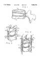
- FIG. 1is a perspective view of an individual vertebra showing the threaded apertures which are formed by insertion of a pair of nut and bolt portions of the present invention
- FIG. 2is a perspective view of two vertebrae and a intervertebral disc showing the threaded apertures which are formed by insertion of two pairs of nut and bolt portions of the present invention
- FIG. 3is a perspective view of the implanted spinal stabilization system of the present invention.
- FIG. 4Ais a perspective view of a preferred embodiment of a single unassembled bolt and nut portions of the present invention.
- FIG. 4Bis a perspective view of a preferred embodiment of another single unassembled bolt and nut portions of the present invention for use with smaller vertebrae;
- FIG. 5is a perspective view of a single assembled bolt and nut portions attached at its ends to rods by tie wires;
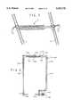
- FIG. 6is a perspective view of an alignment fixture used for installing the spinal stabilization system
- FIG. 7is a horizontal cross-sectional view of the patient and spine and a side view of the alignment fixture in its installation position adjacent the posterior and anterior aspects of the spine;
- FIG. 8is a perspective view of the patient with a posterior incision and the alignment fixture positioned in the installation position.
- the preferred embodiment of the spinal stabilization or fixation system for treating pathological processes or fixing affected vertebrae having anterior and posterior aspectsis generally designated by the reference character 1 and its complete assembly is shown in FIG. 3.
- An example of a pathological process in the spine having affected vertebraeis the common prolapsed invertebral disc; the vertebrae adjacent said disc are the affected vertebrae.
- the systemcomprises conventional, column means 3, three in number, each of which is a rigid elongated rod or plate, one of which is disposed over the anterior aspect of at least two such affected vertebrae, and as shown in this figure two vertebrae, and two of which rods are disposed over the posterior aspects of the two vertebrae.
- FIG. 4Awhich illustrates in detail a single beam means 5 which comprises a pedicle bolt section 7 and a nut section 9, each of which sections are adapted to join each other when they are inserted through a vertebra when the system 1 is installed.
- Each of these bolt and nut sections 7 and 9, respectively,preferably have an aperture or cannulation 11 extending along the longitudinal axes thereof; such cannulation 11 is however optional.
- Each of the bolt and nut sections 7 and 9, respectively,have a cutting end portion 13 and 15, and a front portion 17 and 19, having a cylindrical periphery 21 and 23, respectively, which is externally threaded with cutting edges.
- the aperture 11 of the nut section 9has a cylindrical periphery which is internally threaded for receiving and engaging the threads on the front portion 17 of the bolt section 7.
- the bolt section 7also comprises a middle portion 25 having a cylindrical periphery 27 which is externally threaded with cutting edges; equal diameters are used for the middle and front portions 25 and 19, respectively.
- the middle portion 25is connected to a smooth shaft portion 28.
- Each of the bolt and nut sections 7 and 9, respectively,have a rear portion or ends 29 and 31, respectively, for attaching the ends of said nuts and bolts 7 and 9, respectively, to said rods 3, as is best shown in FIG. 3.
- These ends or attachments 29 and 31are shown as closed and open attachments, respectively, in FIG. 4A, whereas one of said beam means 5 is shown having closed attachments at both ends; after the attachments are installed a staple or a plate (not shown) can be disposed beneath the attachments.
- FIG. 4BAnother preferred embodiment of the beam means 5 is shown in FIG. 4B and is utilized when the system is used for fixing smaller vertebrae.
- Its middle portion 33comprises a smooth shaft portion, the diameter of which is slightly less than the diameter of the threaded portion 21 of the front portion 17.
- Its attachments 29 and 31are of the closed type.
- the preferred embodiment of the alignment fixture used for assisting in the installation of the previously described spinal stabilization system 1is generally designated by the reference character 100 and its complete assembly is shown in FIG. 6.
- the alignment fixture 100comprises L-shaped first and second arms 102 and 104, respectively, drill guide means 106 and an aiming pin 108, all of which are disposed in the same plane.
- Each of the first and second arms 102 and 104, respectivelyhave first and second ends 110, 112 and 114, 116, respectively.
- each of the first and second arms 102 and 104, respectivelyhave first and second straight portions 118, 120 and 122, 124, respectively.
- the first portions 118 and 120 of the first and second arms 102 and 104, respectively,are disposed opposite one another as are their first ends 110 and 112.
- the second portion 122is U-shaped in cross-section and has a narrow slot 135 extending across it length in side walls 136.
- a slide 138extends through the slots 135 and is fixedly attached to the second end 116 of the second portion 124. Accordingly, the second portions 122 and 124 of the first and second arms 102 and 104, respectively, are connected in sliding engagement with one another as are their second ends 114 and 116.
- the aiming pin 108 and the drill guide means 106are axially aligned and fixedly disposed orthogonally on the first ends 110 and 112 of the first portions 118 and 120, respectively, of the first and second arms 102 and 104, respectively.
- the aiming pin 108is generally cylindrical along its length except that its inward end is conically shaped.
- the drill guide means 106comprises a hollow tube which extends inward for most of its length and extends completely through the first end 112 of the second arm 104.
- the aiming pin 108 and the drill guide means 105 on the first and second arms 102 and 104, respectively, of the alignment fixture 100will be utilized and disposed at the anterior and posterior aspects, respectively, of the vertebrae during the initial stages of the installation of the spinal stabilization system 1. Such positioning is accomplished by moving the slide 130 appropriately thereby moving the sliding arms 102 and 104 forward or backwards, until the aiming pin 108 and the drill guide 106 are properly disposed on the anterior and posterior aspects, respectively, of the vertebrae.
- the surgical technique used for implanting the preferred system of the present invention without using the alignment fixtureis generally described as follows (for fixing two levels of affected vertebrae).
- a portion of the spineis surgically exposed anteriorly and posteriorly simultaneously to reveal two levels of vertebrae.
- one or a pair of beam means 5are inserted through an individual vertebra; more specifically one or two pedicle bolt sections 7 each shown as having a cannulation 11, are inserted from posterior to anterior through the vertebra so as to join its opposite bolt section 7; that is the cannulation 11 of each nut section 9 engages the threads on the front portion 17 of each bolt section 7.
- the route in the vertebrae(FIG. 1) can be prepared over a guide wire utilizing a cannula, which requires usage of cannulated bolt and nut sections.
- the cannulated pedicle bolt 7accommodates a Kirschner wire ("k-wire") which is used as a pilot locator bolt 7 and is posteriorly inserted over a properly placed k-wire (not shown) through its central aperture and through the pedicle portion of the vertebra to form a posterior portion of a threaded aperture 35; the nut 9 is similarly inserted over the k-wire anteriorly through its central aperture to form an anterior portion of the threaded aperture 35--this aperture 35 is seen best in FIG. 2.
- k-wireKirschner wire
- the two beam means 5 in an individual vertebraare disposed therein in different planes and form a triangle in cross section through said beam means 5.
- the individual beam means 5extends through the superior and inferior portions of the same vertebra.
- the k-wire guide inside the beams means 5can be replaced with two tie wires 37 which are then twist locked on the rods 3, as seen in FIG. 5, after the beam sections 5 are in place in the vertebrae (not shown in said figure).
- These twist lock attachmentsserve to lock the bolt and nut sections 7 and 9, respectively, to the rods 3 to prevent back-off.
- the improved surgical technique used for implanting the preferred system of the present inventionis essentially the same as the aforedescribed original technique except that the alignment fixture 100 is used in the initial stages of the technique. This improved technique obviates the visual sighting requirement in the original technique which is used to determine the route in the vertebrae.
- the nut section 9has a self-tapping bone screw on its exterior aspects as does the bolt section 7.
- the bolt section 7 of FIG. 4Apreferably has a cutting edge portion 13 around the cannulated opening 11 of 2 mm in length, an externally threaded front portion 17 of greater than between 10 mm to 30 mm in length, an externally threaded middle portion 25 of between 15 mm to 40 mm in length, and a smooth shaft portion 28 of between 20 mm to 40 mm in length.
- the nut section 9 of FIG. 4Apreferably has an externally threaded front portion 19 of about between 10 mm to 30 mm in length, and the aperture 11 thereof has an internal machine thread to meet the machine thread on the tip 13 and front portion 17 of the bolt section 7.
- the pitch of the matching male and female threadsare the same.
- the preferred materials for the bolt and nut sections 7 and 9, respectively,would be T 1 -6AI-4V, or a similar material because of its mechanical strength properties and corrosion resistance; other possible materials could be a high strength biodegradable polymer such as a high molecular weight PLA. Stainless steel could even be used.
Landscapes
- Health & Medical Sciences (AREA)
- Orthopedic Medicine & Surgery (AREA)
- Surgery (AREA)
- Life Sciences & Earth Sciences (AREA)
- Heart & Thoracic Surgery (AREA)
- Animal Behavior & Ethology (AREA)
- Engineering & Computer Science (AREA)
- Biomedical Technology (AREA)
- Neurology (AREA)
- Medical Informatics (AREA)
- Molecular Biology (AREA)
- Nuclear Medicine, Radiotherapy & Molecular Imaging (AREA)
- General Health & Medical Sciences (AREA)
- Public Health (AREA)
- Veterinary Medicine (AREA)
- Dentistry (AREA)
- Oral & Maxillofacial Surgery (AREA)
- Prostheses (AREA)
- Surgical Instruments (AREA)
Abstract
Description
This application is a continuation-in-part of application Ser. No. 07/973,294, filed Nov. 9, 1992 now abandoned.
This invention relates to a system of spinal stabilization, a method for fixing vertebrae and an alignment fixture used to install said system.
Spinal stabilization is a common method to treat pathological processes in the spine and/or sacrum. Stabilization means eliminating movement between adjacent vertebrae, and therefore restoring structural integrity to the spine. Stabilization is achieved by fusing affected vertebrae to each other. The technical objective of stabilization is to achieve a solid bony fusion. This is usually done by creating a "fracture situation" between adjacent affected vertebrae, and fixating them mechanically with metal implants. Once fixation is accomplished, bone healing occurs, creating a fusion mass, which replaces the spanned vertebrae with one solid piece of bone. The task of the implanted instrumentation is to hold fractured or injured bone surfaces rigidly together until healing and fusion occur.
Without bone fusion the stability of a mechanical construct is inadequate. The present surgical state of the art is a circumferential (anterior and posterior) approach, to rebuild the anterior and the posterior mechanical segments of the spinal column separately.
The disadvantages of the circumferential approach are several: too much metal in two different sets of devices; the construct may fail to promote stress sharing and may create stress shielding; and the construct may be too strong for osteogenic bone, and thus cut through it.
A major problem of the present day approach is what to do with poor quality bone or with spines in which adequate attachment of the construct to the bone cannot be achieved.
The present invention in its broadest aspect provides a single spinal stabilization system for fixing affected vertebrae having anterior and posterior aspects. The system comprises a plurality of substantially rigid, elongated column means disposed over the affected vertebrae. At least one of the column means is disposed over the anterior aspect of the affected vertebrae. At least another of the column means is disposed over the posterior aspect of the affected vertebrae. A plurality of substantially rigid, elongated beam means which extend through these affected vertebrae are attached to the column means.
Additionally, the present invention in one of its broadest aspects provides a method of installing a spinal stabilization system to fix affected vertebrae. The steps comprise exposing the spine anteriorly and posteriorly at the level of the affected vertebra, inserting one or a pair of beam means through the affected vertebra, repeating the exposing and inserting steps for a next level of vertebra, disposing column means over the anterior and posterior aspects of the two levels of affected vertebrae, and connecting the ends of the beam means at each affected vertebra level to said column means.
Another feature of the present invention in its broadest aspect is to provide an alignment fixture which accurately place the elements of the spinal stabilization system. The alignment fixture comprises a first and second arm, each arm having first and second ends, a drill guide means and an aiming pin. The arm pin and drill guide means are fixedly connected to the first end of said first and second arms, respectively. The second ends of said first and second arms are connected in sliding engagement with one another. The first and second arms, the drill guide means and the aiming pin are all disposed in the same plane.
Furthermore, the present invention in still another of its broadest aspects, provides a method of installing a spinal stabilization system to fix the vertebrae of a patient using the aligning fixture which has a drill guide at one end and an aiming pin at the other end. This method comprises the steps of:
a. surgically exposing two adjacent levels of affected vertebrae anteriorly and posteriorly;
b. cleaning out the contents of the pedicle portions of the adjacent levels of affected vertebrae so as to permit sufficient movement of the drill guide within the cleaned cut pedicle portions so that the aiming pin can be positioned at the desired exit points on the anterior aspect of the adjacent levels of affected vertebrae;
c. inserting the drill guide within the cleaned out pedicle portions of the adjacent levels of affected vertebrae;
d. positioning the aiming pin at the desired exit points on the anterior aspect of the adjacent levels of affected vertebrae;
inserting a drilling means within the aligned drill guide disposed within the pedicle portions of the adjacent levels of affected vertebrae; and
f. drilling holes through the aligned drill guide into the affected vertebrae to the desired exit points.
The principal object of the invention is to create a rigid structure that will allow successful bony fusion by using a new concept combining anterior and posterior constructs into a single unitary structure achieved at a single surgical sitting.
Another object of the invention is to provide a more rigid construct or cage in which bone and bone graft can heal to a solid fusion.
A further object of the invention is to provide an improved solid construct, in which stress sharing is better distributed between anterior and posterior elements.
An additional object of the invention is to provide an improved method and an alignment fixture for installing such construct or cage.
FIG. 1 is a perspective view of an individual vertebra showing the threaded apertures which are formed by insertion of a pair of nut and bolt portions of the present invention;
FIG. 2 is a perspective view of two vertebrae and a intervertebral disc showing the threaded apertures which are formed by insertion of two pairs of nut and bolt portions of the present invention;
FIG. 3 is a perspective view of the implanted spinal stabilization system of the present invention;
FIG. 4A is a perspective view of a preferred embodiment of a single unassembled bolt and nut portions of the present invention;
FIG. 4B is a perspective view of a preferred embodiment of another single unassembled bolt and nut portions of the present invention for use with smaller vertebrae;
FIG. 5 is a perspective view of a single assembled bolt and nut portions attached at its ends to rods by tie wires;
FIG. 6 is a perspective view of an alignment fixture used for installing the spinal stabilization system;
FIG. 7 is a horizontal cross-sectional view of the patient and spine and a side view of the alignment fixture in its installation position adjacent the posterior and anterior aspects of the spine; and
FIG. 8 is a perspective view of the patient with a posterior incision and the alignment fixture positioned in the installation position.
The preferred embodiment of the spinal stabilization or fixation system for treating pathological processes or fixing affected vertebrae having anterior and posterior aspects is generally designated by the reference character 1 and its complete assembly is shown in FIG. 3. An example of a pathological process in the spine having affected vertebrae is the common prolapsed invertebral disc; the vertebrae adjacent said disc are the affected vertebrae. The system comprises conventional, column means 3, three in number, each of which is a rigid elongated rod or plate, one of which is disposed over the anterior aspect of at least two such affected vertebrae, and as shown in this figure two vertebrae, and two of which rods are disposed over the posterior aspects of the two vertebrae. Theserods 3 are attached to beam means 5, four in number, each of which is a rigid elongated beam means which extends through individual vertebrae. It should be noted however that two or three or more rods could be used. Referring specifically to FIG. 4A, which illustrates in detail a single beam means 5 which comprises a pedicle bolt section 7 and a nut section 9, each of which sections are adapted to join each other when they are inserted through a vertebra when the system 1 is installed. Each of these bolt and nut sections 7 and 9, respectively, preferably have an aperture orcannulation 11 extending along the longitudinal axes thereof;such cannulation 11 is however optional. Each of the bolt and nut sections 7 and 9, respectively, have acutting end portion front portion cylindrical periphery aperture 11 of the nut section 9 has a cylindrical periphery which is internally threaded for receiving and engaging the threads on thefront portion 17 of the bolt section 7. The bolt section 7 also comprises amiddle portion 25 having acylindrical periphery 27 which is externally threaded with cutting edges; equal diameters are used for the middle andfront portions middle portion 25 is connected to asmooth shaft portion 28. Each of the bolt and nut sections 7 and 9, respectively, have a rear portion or ends 29 and 31, respectively, for attaching the ends of said nuts and bolts 7 and 9, respectively, to saidrods 3, as is best shown in FIG. 3. These ends orattachments
Another preferred embodiment of the beam means 5 is shown in FIG. 4B and is utilized when the system is used for fixing smaller vertebrae. Itsmiddle portion 33 comprises a smooth shaft portion, the diameter of which is slightly less than the diameter of the threadedportion 21 of thefront portion 17. Itsattachments
The preferred embodiment of the alignment fixture used for assisting in the installation of the previously described spinal stabilization system 1 is generally designated by thereference character 100 and its complete assembly is shown in FIG. 6. Thealignment fixture 100 comprises L-shaped first andsecond arms pin 108, all of which are disposed in the same plane. Each of the first andsecond arms second arms straight portions first portions second arms first ends second portion 122 is U-shaped in cross-section and has anarrow slot 135 extending across it length inside walls 136. Aslide 138 extends through theslots 135 and is fixedly attached to the second end 116 of thesecond portion 124. Accordingly, thesecond portions second arms pin 108 and the drill guide means 106 are axially aligned and fixedly disposed orthogonally on the first ends 110 and 112 of thefirst portions second arms pin 108 is generally cylindrical along its length except that its inward end is conically shaped. The drill guide means 106 comprises a hollow tube which extends inward for most of its length and extends completely through thefirst end 112 of thesecond arm 104. As discussed below, the aimingpin 108 and the drill guide means 105 on the first andsecond arms alignment fixture 100, will be utilized and disposed at the anterior and posterior aspects, respectively, of the vertebrae during the initial stages of the installation of the spinal stabilization system 1. Such positioning is accomplished by moving theslide 130 appropriately thereby moving the slidingarms pin 108 and thedrill guide 106 are properly disposed on the anterior and posterior aspects, respectively, of the vertebrae.
The surgical technique used for implanting the preferred system of the present invention without using the alignment fixture is generally described as follows (for fixing two levels of affected vertebrae). A portion of the spine is surgically exposed anteriorly and posteriorly simultaneously to reveal two levels of vertebrae. Then one or a pair of beam means 5 are inserted through an individual vertebra; more specifically one or two pedicle bolt sections 7 each shown as having acannulation 11, are inserted from posterior to anterior through the vertebra so as to join its opposite bolt section 7; that is thecannulation 11 of each nut section 9 engages the threads on thefront portion 17 of each bolt section 7. The route in the vertebrae (FIG. 1) can be prepared over a guide wire utilizing a cannula, which requires usage of cannulated bolt and nut sections. The above described procedure is then repeated for the next vertebral level and then three column means or rigidelongated rods 3 are disposed over the anterior and posterior aspects of the two vertebrae and connected to theserods 3. More specifically the rear portions or ends 29 and 31, respectively, of the bolt and nut sections 7 and 9, respectively, are attached to therods 3. Such an implanted spinal stabilization system is shown in FIG. 3. Further aspects of the present invention are as follows: the cannulated pedicle bolt 7 accommodates a Kirschner wire ("k-wire") which is used as a pilot locator bolt 7 and is posteriorly inserted over a properly placed k-wire (not shown) through its central aperture and through the pedicle portion of the vertebra to form a posterior portion of a threadedaperture 35; the nut 9 is similarly inserted over the k-wire anteriorly through its central aperture to form an anterior portion of the threadedaperture 35--thisaperture 35 is seen best in FIG. 2.
As seen in FIG. 2 and FIG. 3 the two beam means 5 in an individual vertebra are disposed therein in different planes and form a triangle in cross section through said beam means 5. Also as seen best in FIG. 1, the individual beam means 5 extends through the superior and inferior portions of the same vertebra. The k-wire guide inside the beams means 5 can be replaced with twotie wires 37 which are then twist locked on therods 3, as seen in FIG. 5, after thebeam sections 5 are in place in the vertebrae (not shown in said figure). These twist lock attachments serve to lock the bolt and nut sections 7 and 9, respectively, to therods 3 to prevent back-off.
The improved surgical technique used for implanting the preferred system of the present invention is essentially the same as the aforedescribed original technique except that thealignment fixture 100 is used in the initial stages of the technique. This improved technique obviates the visual sighting requirement in the original technique which is used to determine the route in the vertebrae.
Referring now to FIGS. 7 and 8, the initial stages or steps of the improved technique or process, which occur prior to the installation of the spinal stabilization system 1 are as follows:
a. surgically exposing two adjacent levels of affected vertebrae;
b. cleaning out the contents of pedicle portions of the above affected vertebrae, preferably by curetting, so as to permit sufficient movement of the drill guide means 106 (of the alignment fixture 100) within the cleaned out pedicle portions so that the aiming pin 108 (of the alignment fixture 100) can be (later) positioned at the desired exit points on the anterior aspect of the above affected vertebrae (these exit points conform to the center of the exit opening ofaperture 35, as is seen best in FIG. 2);
c. making an incision 130 (FIG. 7) in the lateral aspect of apatient 132 of sufficient size to permit the aimingpin 108 and a portion of its attachedarm 102 entry through theincision 130;
d. inserting the aimingpin 108 and a portion of its attachedarm 102 through theincision 130 and positioning the aiming pin 108 (by movingfirst arm 102 inward using the slide) near the anterior aspect of one of the affected vertebrae;
e. inserting the tip of the drill guide means 106 within one of the cleaned out pedicle portions of one affected vertebra (first level);
f. positioning the aimingpin 108 at the desired exit point on the anterior aspect of said one affected vertebrae as is seen best in FIG. 7;
g. inserting the drill bit of a drill 134 (only a portion of which is shown) within the now aligned drill guide means 106 disposed within the pedicle portion of the said one affected vertebra;
h. drilling an aperture into and through the said one affected vertebra, through said drill guide means 106, which emerges at the desired exit point on the anterior aspect of said vertebra;
i. repeating steps e) through h) for the other exit point on the same affected vertebra;
j. inserting a pair of beam means 5 through the same said affected vertebra (first level);
k. repeating steps e) through j) for the second level of affected vertebra;
l. disposing three column means 3 over the anterior and posterior aspects of the two levels of affected vertebrae; and
m. connecting theends
The nut section 9 has a self-tapping bone screw on its exterior aspects as does the bolt section 7. The bolt section 7 of FIG. 4A preferably has acutting edge portion 13 around the cannulatedopening 11 of 2 mm in length, an externally threadedfront portion 17 of greater than between 10 mm to 30 mm in length, an externally threadedmiddle portion 25 of between 15 mm to 40 mm in length, and asmooth shaft portion 28 of between 20 mm to 40 mm in length. The nut section 9 of FIG. 4A preferably has an externally threadedfront portion 19 of about between 10 mm to 30 mm in length, and theaperture 11 thereof has an internal machine thread to meet the machine thread on thetip 13 andfront portion 17 of the bolt section 7. The pitch of the matching male and female threads are the same. The preferred materials for the bolt and nut sections 7 and 9, respectively, would be T1 -6AI-4V, or a similar material because of its mechanical strength properties and corrosion resistance; other possible materials could be a high strength biodegradable polymer such as a high molecular weight PLA. Stainless steel could even be used.
Although the present invention has been described and illustrated with respect to a preferred embodiment; it is not to be so limited since modifications and changes can be made therein which are within the full intended scope of the invention.
Claims (16)
1. A spinal stabilization system for fixing vertebrae bodies having anterior and posterior aspects; said system comprising:
a first, a second and a third substantially rigid, elongated column means each being disposed along an anterior aspect or a posterior aspect of said vertebrae bodies, said first column means being disposed along said anterior aspect of said vertebrae bodies and said second column means being disposed along said posterior aspect of said vertebrae bodies; and
a plurality of substantially rigid, elongated beam means, each beam means of said plurality of beam means having a longitudinal length for extending through said vertebrae bodies, at least from said anterior aspect to said posterior aspect thereof and, each said beam means having a first end and a second end, said each beam means having a first attachment means at said first end and a second attachment means at said second end said first attachment means for coupling said first end to a column means disposed along said anterior aspect of said vertebrae bodies and said second attachment means for coupling said second end to another column means disposed along said posterior aspect of said vertebrae bodies.
2. The system as recited in claim 1, wherein each of said beam means has an aperture extending along its longitudinal axis.
3. A system as recited in claim 1, wherein each said beam means extends through a same vertebra body of said vertebrae bodies and are disposed therein in different planes.
4. A system as recited in claim 1, wherein a column means of said first, second and third column means is selected from the group consisting of rods and plates and wherein there are three column means.
5. A system as recited in claim 1, wherein said first, second and third column means are aligned along said aspects of said vertebrae bodies so that a cross section of said column means through said beam means forms a triangular configuration.
6. A system as recited in claim 1 wherein said vertebrae bodies have superior and inferior rim portions and wherein each said beam means extends through said superior and inferior rim portions of a same vertebra body of said vertebrae bodies.
7. A system as recited in claim 1, wherein each said beam means comprises a bolt section and a nut section adapted to threadingly engage each other between said anterior aspect and said posterior aspect and within a vertebra body of said vertebrae bodies, said bolt section and said nut section each having a longitudinal axis which join each other when said bolt section and said nut section are threadingly engaged within said vertebra body.
8. A system as recited in claim 7, wherein said bolt section and said nut section each have an aperture extending along respective longitudinal axes thereof.
9. A system as recited in claim 7 wherein said bolt section and said nut section each include a cutting end portion and a front portion having an externally threaded cylindrical periphery with cutting edges, and said nut section includes an aperture having an internally threaded cylindrical periphery for engaging said cutting edges of said externally threaded cylindrical periphery of said front portion of said bolt section.
10. A system as recited in claim 9, wherein said bolt section further includes a middle portion having an externally threaded periphery with cutting edges.
11. A system as recited in claim 9 wherein said bolt section and said nut section further include a rear portion and each said rear portion includes an attachment means for attaching said rear portion of said bolt section and said nut section to said column means.
12. A system as recited in claim 10, wherein a diameter of the cylindrical peripheries of said middle portion of said bolt section and said front portion of said nut section are substantially equal.
13. A system as recited in claim 7 wherein said vertebrae bodies have a pedicle portions and said bolt sections extend through the pedicle portions of said vertebrae body.
14. A system as recited in claim 7 wherein said bolt section and said nut section extend from said posterior aspect and said anterior aspect, respectively, of said vertebra body, and toward each other, and engage each other within said vertebra body.
15. A spinal stabilization system for fixing vertebrae bodies having posterior and anterior aspects, said system comprising:
a plurality of column means being selected from a group consisting of rods and plates;
at least two column means of said plurality of column means being disposed over said vertebrae bodies at least one column means of said at least two column means being disposed over an anterior aspect of said vertebrae bodies and at least another column means of said at least two column means being disposed over a posterior aspect of said vertebrae bodies;
a plurality of beam means, each beam means of said plurality of beam means having a longitudinal length for extending through a vertebra body of said vertebrae bodies and for attaching to a column means of said at least two column means at least two beam means of said plurality of beam means extending through a same vertebra body of said vertebrae bodies and on different planes passing through said same vertebra body; and
said each beam means including a bolt section and a nut section each section having a longitudinal axis and an aperture extending along said longitudinal axis each said bolt section and each said nut section including a cutting end portion and a front portion having a cylindrical periphery externally threaded with cutting edges, said aperture of said nut section having a cylindrical periphery internally threaded for engaging said externally threaded cutting edges of said front portion of said bolt section.
16. A spinal stabilization system for fixing vertebrae bodies having anterior and posterior aspects, said system comprising:
a plurality of substantially rigid, elongated column means for being disposed over said vertebrae bodies, at least one column means of said plurality of column means disposed over an anterior aspect of said vertebrae bodies and at least a second column means of said plurality of column means disposed over a posterior aspect of said vertebrae bodies;
a plurality of substantially rigid, elongated beam means, each beam means of said plurality of beam means having a longitudinal length for extending through said vertebrae bodies, said each beam means having first and second ends and first and second attachment means at said first and second ends, respectively, for attaching said beam means to said column means, said each beam means being attached at said first end to a first column means of said plurality of column means which is disposed over said anterior aspect of said vertebrae bodies and said each beam means being attached at said second end to a second column means of said plurality of column means which is disposed over said posterior aspect of said vertebrae bodies;
said each beam means includes a bolt section and a nut section, each having a longitudinal axis which join each other within a vertebra body of said vertebrae bodies, when said bolt section and said nut section are inserted into and through said vertebra body;
said bolt section and said nut section each include a cutting end portion and a front portion having an externally threaded cylindrical periphery, with cutting edges, said nut section including an aperture having an internally threaded cylindrical periphery for engaging said cutting edges of said externally threaded cylindrical periphery of said front portion of said bolt section; and
said each beam means includes a longitudinal aperture and a wire means extending through said longitudinal aperture for attaching said beam means to a column means of said plurality of column means.
Priority Applications (2)
| Application Number | Priority Date | Filing Date | Title |
|---|---|---|---|
| US08/145,603US5562735A (en) | 1992-11-09 | 1993-11-04 | Spinal stabilization system and improved method |
| EP93118144AEP0613662A3 (en) | 1992-11-09 | 1993-11-09 | Spinal stabilization system and method. |
Applications Claiming Priority (2)
| Application Number | Priority Date | Filing Date | Title |
|---|---|---|---|
| US97329492A | 1992-11-09 | 1992-11-09 | |
| US08/145,603US5562735A (en) | 1992-11-09 | 1993-11-04 | Spinal stabilization system and improved method |
Related Parent Applications (1)
| Application Number | Title | Priority Date | Filing Date |
|---|---|---|---|
| US97329492AContinuation-In-Part | 1992-11-09 | 1992-11-09 |
Publications (1)
| Publication Number | Publication Date |
|---|---|
| US5562735Atrue US5562735A (en) | 1996-10-08 |
Family
ID=25520723
Family Applications (2)
| Application Number | Title | Priority Date | Filing Date |
|---|---|---|---|
| US08/145,603Expired - Fee RelatedUS5562735A (en) | 1992-11-09 | 1993-11-04 | Spinal stabilization system and improved method |
| US08/528,801Expired - LifetimeUS5700292A (en) | 1992-11-09 | 1995-09-15 | Spinal stabilization system and method |
Family Applications After (1)
| Application Number | Title | Priority Date | Filing Date |
|---|---|---|---|
| US08/528,801Expired - LifetimeUS5700292A (en) | 1992-11-09 | 1995-09-15 | Spinal stabilization system and method |
Country Status (2)
| Country | Link |
|---|---|
| US (2) | US5562735A (en) |
| CA (1) | CA2102664A1 (en) |
Cited By (95)
| Publication number | Priority date | Publication date | Assignee | Title |
|---|---|---|---|---|
| US5951553A (en)* | 1997-07-14 | 1999-09-14 | Sdgi Holdings, Inc. | Methods and apparatus for fusionless treatment of spinal deformities |
| WO2000062684A1 (en)* | 1999-04-16 | 2000-10-26 | Nuvasive, Inc. | Systems for securing facet joints together |
| US20010002310A1 (en)* | 1997-06-20 | 2001-05-31 | Align Technology, Inc. | Clinician review of an orthodontic treatment plan and appliance |
| US6287308B1 (en) | 1997-07-14 | 2001-09-11 | Sdgi Holdings, Inc. | Methods and apparatus for fusionless treatment of spinal deformities |
| EP1050276A3 (en)* | 1999-05-06 | 2001-11-14 | Bernd Schäfer | Pedicle screw |
| US6342057B1 (en) | 2000-04-28 | 2002-01-29 | Synthes (Usa) | Remotely aligned surgical drill guide |
| US6379364B1 (en) | 2000-04-28 | 2002-04-30 | Synthes (Usa) | Dual drill guide for a locking bone plate |
| US6540747B1 (en) | 1999-04-16 | 2003-04-01 | Nuvasive, Inc. | System for securing joints together |
| US20040002707A1 (en)* | 2002-06-28 | 2004-01-01 | Chunfeng Zhao | Spinal fixation support device and methods of using |
| US7041136B2 (en) | 2000-11-29 | 2006-05-09 | Facet Solutions, Inc. | Facet joint replacement |
| US7074237B2 (en) | 2000-12-13 | 2006-07-11 | Facet Solutions, Inc. | Multiple facet joint replacement |
| US7090698B2 (en) | 2001-03-02 | 2006-08-15 | Facet Solutions | Method and apparatus for spine joint replacement |
| US20070043361A1 (en)* | 2005-02-17 | 2007-02-22 | Malandain Hugues F | Percutaneous spinal implants and methods |
| US20080055512A1 (en)* | 2006-08-31 | 2008-03-06 | Tae Hyuck Kim | Liquid crystal display |
| US20080081896A1 (en)* | 2006-09-28 | 2008-04-03 | Helmut-Werner Heuer | (Co)polycarbonates having improved adhesion to metals |
| US7507242B2 (en) | 2004-06-02 | 2009-03-24 | Facet Solutions | Surgical measurement and resection framework |
| US7566345B1 (en) | 2001-03-01 | 2009-07-28 | Facet Solutions, Inc | Prosthesis for the replacement of a posterior element of a vertebra |
| US7588590B2 (en) | 2003-12-10 | 2009-09-15 | Facet Solutions, Inc | Spinal facet implant with spherical implant apposition surface and bone bed and methods of use |
| US20100070035A1 (en)* | 2008-09-18 | 2010-03-18 | Mayer Peter L | Intervertebral disc prosthesis and method for implanting and explanting |
| US7722647B1 (en) | 2005-03-14 | 2010-05-25 | Facet Solutions, Inc. | Apparatus and method for posterior vertebral stabilization |
| US7776069B2 (en) | 2002-09-10 | 2010-08-17 | Kyphon SÀRL | Posterior vertebral support assembly |
| US7799081B2 (en) | 2004-09-14 | 2010-09-21 | Aeolin, Llc | System and method for spinal fusion |
| US7803190B2 (en) | 2002-10-29 | 2010-09-28 | Kyphon SÀRL | Interspinous process apparatus and method with a selectably expandable spacer |
| US7846186B2 (en) | 2005-06-28 | 2010-12-07 | Kyphon SÀRL | Equipment for surgical treatment of two vertebrae |
| US7879104B2 (en) | 2006-11-15 | 2011-02-01 | Warsaw Orthopedic, Inc. | Spinal implant system |
| US7901432B2 (en) | 1997-01-02 | 2011-03-08 | Kyphon Sarl | Method for lateral implantation of spinous process spacer |
| US20110071576A1 (en)* | 2009-09-23 | 2011-03-24 | Hadi Bassam A | Bone Bolt Assembly for Attaching Supporting Implants to Bones, for Holding Multiple Bones in Relative Positions, and for Holding Together Fractured Bone Fragments |
| US7927354B2 (en) | 2005-02-17 | 2011-04-19 | Kyphon Sarl | Percutaneous spinal implants and methods |
| US7931674B2 (en) | 2005-03-21 | 2011-04-26 | Kyphon Sarl | Interspinous process implant having deployable wing and method of implantation |
| US7955392B2 (en) | 2006-12-14 | 2011-06-07 | Warsaw Orthopedic, Inc. | Interspinous process devices and methods |
| US7959652B2 (en) | 2005-04-18 | 2011-06-14 | Kyphon Sarl | Interspinous process implant having deployable wings and method of implantation |
| US7959679B2 (en) | 1999-08-18 | 2011-06-14 | Intrinsic Therapeutics, Inc. | Intervertebral anulus and nucleus augmentation |
| US7972337B2 (en) | 2005-12-28 | 2011-07-05 | Intrinsic Therapeutics, Inc. | Devices and methods for bone anchoring |
| US7988709B2 (en) | 2005-02-17 | 2011-08-02 | Kyphon Sarl | Percutaneous spinal implants and methods |
| US7993374B2 (en) | 1997-01-02 | 2011-08-09 | Kyphon Sarl | Supplemental spine fixation device and method |
| US7993373B2 (en) | 2005-02-22 | 2011-08-09 | Hoy Robert W | Polyaxial orthopedic fastening apparatus |
| US7998174B2 (en) | 2005-02-17 | 2011-08-16 | Kyphon Sarl | Percutaneous spinal implants and methods |
| US8002836B2 (en) | 1999-08-18 | 2011-08-23 | Intrinsic Therapeutics, Inc. | Method for the treatment of the intervertebral disc anulus |
| US8007537B2 (en) | 2002-10-29 | 2011-08-30 | Kyphon Sarl | Interspinous process implants and methods of use |
| US8007521B2 (en) | 2005-02-17 | 2011-08-30 | Kyphon Sarl | Percutaneous spinal implants and methods |
| US8021425B2 (en)* | 1999-08-18 | 2011-09-20 | Intrinsic Therapeutics, Inc. | Versatile method of repairing an intervertebral disc |
| US8029567B2 (en) | 2005-02-17 | 2011-10-04 | Kyphon Sarl | Percutaneous spinal implants and methods |
| US8034079B2 (en) | 2005-04-12 | 2011-10-11 | Warsaw Orthopedic, Inc. | Implants and methods for posterior dynamic stabilization of a spinal motion segment |
| US8034080B2 (en) | 2005-02-17 | 2011-10-11 | Kyphon Sarl | Percutaneous spinal implants and methods |
| US8038698B2 (en) | 2005-02-17 | 2011-10-18 | Kphon Sarl | Percutaneous spinal implants and methods |
| US8043378B2 (en) | 2006-09-07 | 2011-10-25 | Warsaw Orthopedic, Inc. | Intercostal spacer device and method for use in correcting a spinal deformity |
| US8048117B2 (en) | 2003-05-22 | 2011-11-01 | Kyphon Sarl | Interspinous process implant and method of implantation |
| US8048119B2 (en) | 2006-07-20 | 2011-11-01 | Warsaw Orthopedic, Inc. | Apparatus for insertion between anatomical structures and a procedure utilizing same |
| US8048118B2 (en) | 2006-04-28 | 2011-11-01 | Warsaw Orthopedic, Inc. | Adjustable interspinous process brace |
| US8057513B2 (en) | 2005-02-17 | 2011-11-15 | Kyphon Sarl | Percutaneous spinal implants and methods |
| US8070778B2 (en) | 2003-05-22 | 2011-12-06 | Kyphon Sarl | Interspinous process implant with slide-in distraction piece and method of implantation |
| US8083795B2 (en) | 2006-01-18 | 2011-12-27 | Warsaw Orthopedic, Inc. | Intervertebral prosthetic device for spinal stabilization and method of manufacturing same |
| US8096994B2 (en) | 2005-02-17 | 2012-01-17 | Kyphon Sarl | Percutaneous spinal implants and methods |
| US8097018B2 (en) | 2005-02-17 | 2012-01-17 | Kyphon Sarl | Percutaneous spinal implants and methods |
| US8096995B2 (en) | 2005-02-17 | 2012-01-17 | Kyphon Sarl | Percutaneous spinal implants and methods |
| US8100943B2 (en) | 2005-02-17 | 2012-01-24 | Kyphon Sarl | Percutaneous spinal implants and methods |
| US8105358B2 (en) | 2008-02-04 | 2012-01-31 | Kyphon Sarl | Medical implants and methods |
| US8114131B2 (en) | 2008-11-05 | 2012-02-14 | Kyphon Sarl | Extension limiting devices and methods of use for the spine |
| US8114132B2 (en) | 2010-01-13 | 2012-02-14 | Kyphon Sarl | Dynamic interspinous process device |
| US8114136B2 (en) | 2008-03-18 | 2012-02-14 | Warsaw Orthopedic, Inc. | Implants and methods for inter-spinous process dynamic stabilization of a spinal motion segment |
| US8118839B2 (en) | 2006-11-08 | 2012-02-21 | Kyphon Sarl | Interspinous implant |
| US8118844B2 (en) | 2006-04-24 | 2012-02-21 | Warsaw Orthopedic, Inc. | Expandable device for insertion between anatomical structures and a procedure utilizing same |
| US8128663B2 (en) | 1997-01-02 | 2012-03-06 | Kyphon Sarl | Spine distraction implant |
| US8147526B2 (en) | 2010-02-26 | 2012-04-03 | Kyphon Sarl | Interspinous process spacer diagnostic parallel balloon catheter and methods of use |
| US8147548B2 (en) | 2005-03-21 | 2012-04-03 | Kyphon Sarl | Interspinous process implant having a thread-shaped wing and method of implantation |
| US8157842B2 (en) | 2009-06-12 | 2012-04-17 | Kyphon Sarl | Interspinous implant and methods of use |
| US8157841B2 (en) | 2005-02-17 | 2012-04-17 | Kyphon Sarl | Percutaneous spinal implants and methods |
| US20120156644A1 (en)* | 2010-12-20 | 2012-06-21 | Warsaw Orthopedic, Inc. | Bone augmentation device and method |
| US8206418B2 (en) | 2007-01-10 | 2012-06-26 | Gmedelaware 2 Llc | System and method for facet joint replacement with detachable coupler |
| US8226653B2 (en) | 2005-04-29 | 2012-07-24 | Warsaw Orthopedic, Inc. | Spinous process stabilization devices and methods |
| US8231678B2 (en) | 1999-08-18 | 2012-07-31 | Intrinsic Therapeutics, Inc. | Method of treating a herniated disc |
| US8262698B2 (en) | 2006-03-16 | 2012-09-11 | Warsaw Orthopedic, Inc. | Expandable device for insertion between anatomical structures and a procedure utilizing same |
| US20120265304A1 (en)* | 2008-09-18 | 2012-10-18 | Mayer Peter L | Intervertebral disc prosthesis, method for assembling, method for implanting prosthesis, and method for explanting |
| US8317831B2 (en) | 2010-01-13 | 2012-11-27 | Kyphon Sarl | Interspinous process spacer diagnostic balloon catheter and methods of use |
| US8323341B2 (en) | 2007-09-07 | 2012-12-04 | Intrinsic Therapeutics, Inc. | Impaction grafting for vertebral fusion |
| US8349013B2 (en) | 1997-01-02 | 2013-01-08 | Kyphon Sarl | Spine distraction implant |
| US8372117B2 (en) | 2009-06-05 | 2013-02-12 | Kyphon Sarl | Multi-level interspinous implants and methods of use |
| US8454612B2 (en) | 2007-09-07 | 2013-06-04 | Intrinsic Therapeutics, Inc. | Method for vertebral endplate reconstruction |
| US8470046B2 (en)* | 2011-04-25 | 2013-06-25 | Warsaw Orthopedic, Inc. | Bone augmentation device and method |
| US8556936B2 (en) | 2000-11-29 | 2013-10-15 | Gmedelaware 2 Llc | Facet joint replacement |
| US8562649B2 (en) | 2004-02-17 | 2013-10-22 | Gmedelaware 2 Llc | System and method for multiple level facet joint arthroplasty and fusion |
| US8591549B2 (en) | 2011-04-08 | 2013-11-26 | Warsaw Orthopedic, Inc. | Variable durometer lumbar-sacral implant |
| US8591548B2 (en) | 2011-03-31 | 2013-11-26 | Warsaw Orthopedic, Inc. | Spinous process fusion plate assembly |
| US8641762B2 (en) | 2006-10-24 | 2014-02-04 | Warsaw Orthopedic, Inc. | Systems and methods for in situ assembly of an interspinous process distraction implant |
| WO2014026129A1 (en)* | 2012-08-10 | 2014-02-13 | Brennan M D William A | Spinal stabilization system and method |
| US8679161B2 (en) | 2005-02-17 | 2014-03-25 | Warsaw Orthopedic, Inc. | Percutaneous spinal implants and methods |
| US8764801B2 (en) | 2005-03-28 | 2014-07-01 | Gmedelaware 2 Llc | Facet joint implant crosslinking apparatus and method |
| US8771317B2 (en) | 2009-10-28 | 2014-07-08 | Warsaw Orthopedic, Inc. | Interspinous process implant and method of implantation |
| US8814908B2 (en) | 2010-07-26 | 2014-08-26 | Warsaw Orthopedic, Inc. | Injectable flexible interspinous process device system |
| US8900273B2 (en) | 2005-02-22 | 2014-12-02 | Gmedelaware 2 Llc | Taper-locking fixation system |
| US9364339B2 (en) | 2012-04-30 | 2016-06-14 | Peter L. Mayer | Unilaterally placed expansile spinal prosthesis |
| US9393126B2 (en) | 2012-04-20 | 2016-07-19 | Peter L. Mayer | Bilaterally placed disc prosthesis for spinal implant and method of bilateral placement |
| US9561055B1 (en)* | 2012-01-18 | 2017-02-07 | Neurosurj Research and Development, LLC | Spinal fixation method and apparatus |
| US20170049485A1 (en)* | 2015-08-21 | 2017-02-23 | Scott Meyer | Pedicle screw placement system and method for spinal surgery |
| US9706947B2 (en) | 1999-08-18 | 2017-07-18 | Intrinsic Therapeutics, Inc. | Method of performing an anchor implantation procedure within a disc |
Families Citing this family (85)
| Publication number | Priority date | Publication date | Assignee | Title |
|---|---|---|---|---|
| EP0934026B1 (en) | 1996-10-24 | 2009-07-15 | Zimmer Spine Austin, Inc | Apparatus for spinal fixation |
| US6416515B1 (en) | 1996-10-24 | 2002-07-09 | Spinal Concepts, Inc. | Spinal fixation system |
| US6045579A (en) | 1997-05-01 | 2000-04-04 | Spinal Concepts, Inc. | Adjustable height fusion device |
| US5928243A (en) | 1997-07-16 | 1999-07-27 | Spinal Concepts, Inc. | Pedicle probe and depth gage |
| US6454769B2 (en) | 1997-08-04 | 2002-09-24 | Spinal Concepts, Inc. | System and method for stabilizing the human spine with a bone plate |
| US6030389A (en) | 1997-08-04 | 2000-02-29 | Spinal Concepts, Inc. | System and method for stabilizing the human spine with a bone plate |
| US6053921A (en) | 1997-08-26 | 2000-04-25 | Spinal Concepts, Inc. | Surgical cable system and method |
| US5964769A (en) | 1997-08-26 | 1999-10-12 | Spinal Concepts, Inc. | Surgical cable system and method |
| US6251140B1 (en) | 1998-05-27 | 2001-06-26 | Nuvasive, Inc. | Interlocking spinal inserts |
| US6368325B1 (en) | 1998-05-27 | 2002-04-09 | Nuvasive, Inc. | Bone blocks and methods for inserting bone blocks into intervertebral spaces |
| US6290724B1 (en) | 1998-05-27 | 2001-09-18 | Nuvasive, Inc. | Methods for separating and stabilizing adjacent vertebrae |
| CA2363254C (en) | 1999-03-07 | 2009-05-05 | Discure Ltd. | Method and apparatus for computerized surgery |
| US6331179B1 (en) | 2000-01-06 | 2001-12-18 | Spinal Concepts, Inc. | System and method for stabilizing the human spine with a bone plate |
| US6852126B2 (en) | 2000-07-17 | 2005-02-08 | Nuvasive, Inc. | Stackable interlocking intervertebral support system |
| US6969610B2 (en)* | 2001-01-12 | 2005-11-29 | University Of Rochester | Methods of modifying cell structure and remodeling tissue |
| US6923814B1 (en) | 2001-10-30 | 2005-08-02 | Nuvasive, Inc. | System and methods for cervical spinal fusion |
| US7766947B2 (en) | 2001-10-31 | 2010-08-03 | Ortho Development Corporation | Cervical plate for stabilizing the human spine |
| EP1482877B1 (en) | 2002-03-11 | 2007-05-30 | Spinal Concepts Inc. | Instrumentation for implanting spinal implant devices |
| US7618423B1 (en) | 2002-06-15 | 2009-11-17 | Nuvasive, Inc. | System and method for performing spinal fusion |
| US7066938B2 (en) | 2002-09-09 | 2006-06-27 | Depuy Spine, Inc. | Snap-on spinal rod connector |
| US7776049B1 (en) | 2002-10-02 | 2010-08-17 | Nuvasive, Inc. | Spinal implant inserter, implant, and method |
| US6966929B2 (en) | 2002-10-29 | 2005-11-22 | St. Francis Medical Technologies, Inc. | Artificial vertebral disk replacement implant with a spacer |
| US7273496B2 (en) | 2002-10-29 | 2007-09-25 | St. Francis Medical Technologies, Inc. | Artificial vertebral disk replacement implant with crossbar spacer and method |
| US7083649B2 (en) | 2002-10-29 | 2006-08-01 | St. Francis Medical Technologies, Inc. | Artificial vertebral disk replacement implant with translating pivot point |
| US7497859B2 (en) | 2002-10-29 | 2009-03-03 | Kyphon Sarl | Tools for implanting an artificial vertebral disk |
| US7520899B2 (en) | 2003-11-05 | 2009-04-21 | Kyphon Sarl | Laterally insertable artificial vertebral disk replacement implant with crossbar spacer |
| US7670377B2 (en) | 2003-11-21 | 2010-03-02 | Kyphon Sarl | Laterally insertable artifical vertebral disk replacement implant with curved spacer |
| US20050154462A1 (en) | 2003-12-02 | 2005-07-14 | St. Francis Medical Technologies, Inc. | Laterally insertable artificial vertebral disk replacement implant with translating pivot point |
| US7481839B2 (en) | 2003-12-02 | 2009-01-27 | Kyphon Sarl | Bioresorbable interspinous process implant for use with intervertebral disk remediation or replacement implants and procedures |
| US7918891B1 (en) | 2004-03-29 | 2011-04-05 | Nuvasive Inc. | Systems and methods for spinal fusion |
| US7717939B2 (en) | 2004-03-31 | 2010-05-18 | Depuy Spine, Inc. | Rod attachment for head to head cross connector |
| US7645294B2 (en) | 2004-03-31 | 2010-01-12 | Depuy Spine, Inc. | Head-to-head connector spinal fixation system |
| US7717938B2 (en) | 2004-08-27 | 2010-05-18 | Depuy Spine, Inc. | Dual rod cross connectors and inserter tools |
| US7575600B2 (en) | 2004-09-29 | 2009-08-18 | Kyphon Sarl | Artificial vertebral disk replacement implant with translating articulation contact surface and method |
| US7481840B2 (en)* | 2004-09-29 | 2009-01-27 | Kyphon Sarl | Multi-piece artificial spinal disk replacement device with selectably positioning articulating element |
| USD530423S1 (en) | 2005-03-29 | 2006-10-17 | Nuvasive, Inc. | Intervertebral implant |
| US8623088B1 (en) | 2005-07-15 | 2014-01-07 | Nuvasive, Inc. | Spinal fusion implant and related methods |
| US8328851B2 (en) | 2005-07-28 | 2012-12-11 | Nuvasive, Inc. | Total disc replacement system and related methods |
| US7837711B2 (en) | 2006-01-27 | 2010-11-23 | Warsaw Orthopedic, Inc. | Artificial spinous process for the sacrum and methods of use |
| US20080058808A1 (en) | 2006-06-14 | 2008-03-06 | Spartek Medical, Inc. | Implant system and method to treat degenerative disorders of the spine |
| USD741488S1 (en) | 2006-07-17 | 2015-10-20 | Nuvasive, Inc. | Spinal fusion implant |
| US9017388B2 (en)* | 2006-09-14 | 2015-04-28 | Warsaw Orthopedic, Inc. | Methods for correcting spinal deformities |
| US8361117B2 (en) | 2006-11-08 | 2013-01-29 | Depuy Spine, Inc. | Spinal cross connectors |
| US8673005B1 (en) | 2007-03-07 | 2014-03-18 | Nuvasive, Inc. | System and methods for spinal fusion |
| US8480715B2 (en) | 2007-05-22 | 2013-07-09 | Zimmer Spine, Inc. | Spinal implant system and method |
| US8048115B2 (en) | 2007-06-05 | 2011-11-01 | Spartek Medical, Inc. | Surgical tool and method for implantation of a dynamic bone anchor |
| US8109970B2 (en) | 2007-06-05 | 2012-02-07 | Spartek Medical, Inc. | Deflection rod system with a deflection contouring shield for a spine implant and method |
| US8052722B2 (en) | 2007-06-05 | 2011-11-08 | Spartek Medical, Inc. | Dual deflection rod system for a dynamic stabilization and motion preservation spinal implantation system and method |
| US8083772B2 (en) | 2007-06-05 | 2011-12-27 | Spartek Medical, Inc. | Dynamic spinal rod assembly and method for dynamic stabilization of the spine |
| US8092501B2 (en) | 2007-06-05 | 2012-01-10 | Spartek Medical, Inc. | Dynamic spinal rod and method for dynamic stabilization of the spine |
| US8048123B2 (en) | 2007-06-05 | 2011-11-01 | Spartek Medical, Inc. | Spine implant with a deflection rod system and connecting linkages and method |
| US8021396B2 (en) | 2007-06-05 | 2011-09-20 | Spartek Medical, Inc. | Configurable dynamic spinal rod and method for dynamic stabilization of the spine |
| US8048128B2 (en) | 2007-06-05 | 2011-11-01 | Spartek Medical, Inc. | Revision system and method for a dynamic stabilization and motion preservation spinal implantation system and method |
| US8114134B2 (en) | 2007-06-05 | 2012-02-14 | Spartek Medical, Inc. | Spinal prosthesis having a three bar linkage for motion preservation and dynamic stabilization of the spine |
| USD671645S1 (en) | 2007-09-18 | 2012-11-27 | Nuvasive, Inc. | Intervertebral implant |
| US9101491B2 (en) | 2007-12-28 | 2015-08-11 | Nuvasive, Inc. | Spinal surgical implant and related methods |
| US8048125B2 (en) | 2008-02-26 | 2011-11-01 | Spartek Medical, Inc. | Versatile offset polyaxial connector and method for dynamic stabilization of the spine |
| US8337536B2 (en) | 2008-02-26 | 2012-12-25 | Spartek Medical, Inc. | Load-sharing bone anchor having a deflectable post with a compliant ring and method for stabilization of the spine |
| US8211155B2 (en) | 2008-02-26 | 2012-07-03 | Spartek Medical, Inc. | Load-sharing bone anchor having a durable compliant member and method for dynamic stabilization of the spine |
| US8083775B2 (en) | 2008-02-26 | 2011-12-27 | Spartek Medical, Inc. | Load-sharing bone anchor having a natural center of rotation and method for dynamic stabilization of the spine |
| US8057517B2 (en) | 2008-02-26 | 2011-11-15 | Spartek Medical, Inc. | Load-sharing component having a deflectable post and centering spring and method for dynamic stabilization of the spine |
| US8097024B2 (en) | 2008-02-26 | 2012-01-17 | Spartek Medical, Inc. | Load-sharing bone anchor having a deflectable post and method for stabilization of the spine |
| US8267979B2 (en) | 2008-02-26 | 2012-09-18 | Spartek Medical, Inc. | Load-sharing bone anchor having a deflectable post and axial spring and method for dynamic stabilization of the spine |
| US8007518B2 (en) | 2008-02-26 | 2011-08-30 | Spartek Medical, Inc. | Load-sharing component having a deflectable post and method for dynamic stabilization of the spine |
| US8333792B2 (en) | 2008-02-26 | 2012-12-18 | Spartek Medical, Inc. | Load-sharing bone anchor having a deflectable post and method for dynamic stabilization of the spine |
| US8083796B1 (en) | 2008-02-29 | 2011-12-27 | Nuvasive, Inc. | Implants and methods for spinal fusion |
| USD599019S1 (en) | 2008-03-07 | 2009-08-25 | Nuvasive, Inc. | Spinal fusion implant |
| US7909857B2 (en)* | 2008-03-26 | 2011-03-22 | Warsaw Orthopedic, Inc. | Devices and methods for correcting spinal deformities |
| USD621509S1 (en) | 2008-10-15 | 2010-08-10 | Nuvasive, Inc. | Intervertebral implant |
| USD754346S1 (en) | 2009-03-02 | 2016-04-19 | Nuvasive, Inc. | Spinal fusion implant |
| US9387090B2 (en) | 2009-03-12 | 2016-07-12 | Nuvasive, Inc. | Vertebral body replacement |
| US9687357B2 (en) | 2009-03-12 | 2017-06-27 | Nuvasive, Inc. | Vertebral body replacement |
| US9351845B1 (en) | 2009-04-16 | 2016-05-31 | Nuvasive, Inc. | Method and apparatus for performing spine surgery |
| US8287597B1 (en) | 2009-04-16 | 2012-10-16 | Nuvasive, Inc. | Method and apparatus for performing spine surgery |
| USD731063S1 (en) | 2009-10-13 | 2015-06-02 | Nuvasive, Inc. | Spinal fusion implant |
| CN102695465A (en) | 2009-12-02 | 2012-09-26 | 斯帕泰克医疗股份有限公司 | Low profile spinal prosthesis incorporating a bone anchor having a deflectable post and a compound spinal rod |
| US20110307015A1 (en) | 2010-06-10 | 2011-12-15 | Spartek Medical, Inc. | Adaptive spinal rod and methods for stabilization of the spine |
| US9198765B1 (en) | 2011-10-31 | 2015-12-01 | Nuvasive, Inc. | Expandable spinal fusion implants and related methods |
| USD721808S1 (en) | 2011-11-03 | 2015-01-27 | Nuvasive, Inc. | Intervertebral implant |
| USD675320S1 (en) | 2011-11-03 | 2013-01-29 | Nuvasive, Inc. | Intervertebral implant |
| US8430916B1 (en) | 2012-02-07 | 2013-04-30 | Spartek Medical, Inc. | Spinal rod connectors, methods of use, and spinal prosthesis incorporating spinal rod connectors |
| USD745159S1 (en) | 2013-10-10 | 2015-12-08 | Nuvasive, Inc. | Intervertebral implant |
| US10478313B1 (en) | 2014-01-10 | 2019-11-19 | Nuvasive, Inc. | Spinal fusion implant and related methods |
| USD858769S1 (en) | 2014-11-20 | 2019-09-03 | Nuvasive, Inc. | Intervertebral implant |
| WO2025096361A1 (en)* | 2023-10-30 | 2025-05-08 | Combination Spine, Inc. | Devices and methods for anterior transpedicular fixation and posterior revision |
Citations (4)
| Publication number | Priority date | Publication date | Assignee | Title |
|---|---|---|---|---|
| US3900025A (en)* | 1974-04-24 | 1975-08-19 | Jr Walter P Barnes | Apparatus for distracting or compressing longitudinal bone segments |
| SU829104A1 (en)* | 1979-07-19 | 1981-05-15 | Ворошиловградский Государственныймедицинский Институт | Ultrasonic transducer |
| US4456005A (en)* | 1982-09-30 | 1984-06-26 | Lichty Terry K | External compression bone fixation device |
| US4913134A (en)* | 1987-07-24 | 1990-04-03 | Biotechnology, Inc. | Spinal fixation system |
Family Cites Families (19)
| Publication number | Priority date | Publication date | Assignee | Title |
|---|---|---|---|---|
| US3848601A (en)* | 1972-06-14 | 1974-11-19 | G Ma | Method for interbody fusion of the spine |
| GB1551705A (en)* | 1975-04-28 | 1979-08-30 | Downs Surgicial Ltd | Surgial implant |
| SU644473A1 (en)* | 1977-01-18 | 1979-01-30 | Крымский Государственный Медицинский Институт | Spinal column fixing device |
| SU770482A1 (en)* | 1977-03-01 | 1980-10-15 | Valentin A Korokhin | Compression distraction apparatus |
| CA1146301A (en)* | 1980-06-13 | 1983-05-17 | J. David Kuntz | Intervertebral disc prosthesis |
| US4479491A (en)* | 1982-07-26 | 1984-10-30 | Martin Felix M | Intervertebral stabilization implant |
| US4554914A (en)* | 1983-10-04 | 1985-11-26 | Kapp John P | Prosthetic vertebral body |
| US4573454A (en)* | 1984-05-17 | 1986-03-04 | Hoffman Gregory A | Spinal fixation apparatus |
| US4599086A (en)* | 1985-06-07 | 1986-07-08 | Doty James R | Spine stabilization device and method |
| SU1540812A1 (en)* | 1986-05-13 | 1990-02-07 | Хабаровский государственный медицинский институт | Compression-distraction apparatus |
| US5007909A (en)* | 1986-11-05 | 1991-04-16 | Chaim Rogozinski | Apparatus for internally fixing the spine |
| US4834757A (en)* | 1987-01-22 | 1989-05-30 | Brantigan John W | Prosthetic implant |
| US4858601A (en)* | 1988-05-27 | 1989-08-22 | Glisson Richard R | Adjustable compression bone screw |
| US5015247A (en)* | 1988-06-13 | 1991-05-14 | Michelson Gary K | Threaded spinal implant |
| SU1598991A1 (en)* | 1988-06-23 | 1990-10-15 | Чувашский государственный университет им.И.Н.Ульянова | Compression-distraction apparatus |
| US4936848A (en)* | 1989-09-22 | 1990-06-26 | Bagby George W | Implant for vertebrae |
| US5055104A (en)* | 1989-11-06 | 1991-10-08 | Surgical Dynamics, Inc. | Surgically implanting threaded fusion cages between adjacent low-back vertebrae by an anterior approach |
| US5062850A (en)* | 1990-01-16 | 1991-11-05 | University Of Florida | Axially-fixed vertebral body prosthesis and method of fixation |
| US5127912A (en)* | 1990-10-05 | 1992-07-07 | R. Charles Ray | Sacral implant system |
- 1993
- 1993-11-04USUS08/145,603patent/US5562735A/ennot_activeExpired - Fee Related
- 1993-11-08CACA002102664Apatent/CA2102664A1/ennot_activeAbandoned
- 1995
- 1995-09-15USUS08/528,801patent/US5700292A/ennot_activeExpired - Lifetime
Patent Citations (4)
| Publication number | Priority date | Publication date | Assignee | Title |
|---|---|---|---|---|
| US3900025A (en)* | 1974-04-24 | 1975-08-19 | Jr Walter P Barnes | Apparatus for distracting or compressing longitudinal bone segments |
| SU829104A1 (en)* | 1979-07-19 | 1981-05-15 | Ворошиловградский Государственныймедицинский Институт | Ultrasonic transducer |
| US4456005A (en)* | 1982-09-30 | 1984-06-26 | Lichty Terry K | External compression bone fixation device |
| US4913134A (en)* | 1987-07-24 | 1990-04-03 | Biotechnology, Inc. | Spinal fixation system |
Cited By (168)
| Publication number | Priority date | Publication date | Assignee | Title |
|---|---|---|---|---|
| US8617211B2 (en) | 1997-01-02 | 2013-12-31 | Warsaw Orthopedic, Inc. | Spine distraction implant and method |
| US8828017B2 (en) | 1997-01-02 | 2014-09-09 | Warsaw Orthopedic, Inc. | Spine distraction implant and method |
| US8157840B2 (en) | 1997-01-02 | 2012-04-17 | Kyphon Sarl | Spine distraction implant and method |
| US8740943B2 (en) | 1997-01-02 | 2014-06-03 | Warsaw Orthopedic, Inc. | Spine distraction implant and method |
| US7993374B2 (en) | 1997-01-02 | 2011-08-09 | Kyphon Sarl | Supplemental spine fixation device and method |
| US7918877B2 (en) | 1997-01-02 | 2011-04-05 | Kyphon Sarl | Lateral insertion method for spinous process spacer with deployable member |
| US8349013B2 (en) | 1997-01-02 | 2013-01-08 | Kyphon Sarl | Spine distraction implant |
| US8821548B2 (en) | 1997-01-02 | 2014-09-02 | Warsaw Orthopedic, Inc. | Spine distraction implant and method |
| US8128663B2 (en) | 1997-01-02 | 2012-03-06 | Kyphon Sarl | Spine distraction implant |
| US8540751B2 (en) | 1997-01-02 | 2013-09-24 | Warsaw Orthopedic, Inc. | Spine distraction implant and method |
| US7901432B2 (en) | 1997-01-02 | 2011-03-08 | Kyphon Sarl | Method for lateral implantation of spinous process spacer |
| US7955356B2 (en) | 1997-01-02 | 2011-06-07 | Kyphon Sarl | Laterally insertable interspinous process implant |
| US8568455B2 (en)* | 1997-01-02 | 2013-10-29 | Warsaw Orthopedic, Inc. | Spine distraction implant and method |
| US8568454B2 (en) | 1997-01-02 | 2013-10-29 | Warsaw Orthopedic, Inc. | Spine distraction implant and method |
| US20010002310A1 (en)* | 1997-06-20 | 2001-05-31 | Align Technology, Inc. | Clinician review of an orthodontic treatment plan and appliance |
| US5951553A (en)* | 1997-07-14 | 1999-09-14 | Sdgi Holdings, Inc. | Methods and apparatus for fusionless treatment of spinal deformities |
| US6623484B2 (en) | 1997-07-14 | 2003-09-23 | Sdgi Holdings, Inc. | Methods and apparatus for fusionless treatment of spinal deformities |
| US6287308B1 (en) | 1997-07-14 | 2001-09-11 | Sdgi Holdings, Inc. | Methods and apparatus for fusionless treatment of spinal deformities |
| US6540747B1 (en) | 1999-04-16 | 2003-04-01 | Nuvasive, Inc. | System for securing joints together |
| WO2000062684A1 (en)* | 1999-04-16 | 2000-10-26 | Nuvasive, Inc. | Systems for securing facet joints together |
| EP1050276A3 (en)* | 1999-05-06 | 2001-11-14 | Bernd Schäfer | Pedicle screw |
| US8257437B2 (en) | 1999-08-18 | 2012-09-04 | Intrinsic Therapeutics, Inc. | Methods of intervertebral disc augmentation |
| US8021425B2 (en)* | 1999-08-18 | 2011-09-20 | Intrinsic Therapeutics, Inc. | Versatile method of repairing an intervertebral disc |
| US8025698B2 (en) | 1999-08-18 | 2011-09-27 | Intrinsic Therapeutics, Inc. | Method of rehabilitating an anulus fibrosus |
| US7959679B2 (en) | 1999-08-18 | 2011-06-14 | Intrinsic Therapeutics, Inc. | Intervertebral anulus and nucleus augmentation |
| US8002836B2 (en) | 1999-08-18 | 2011-08-23 | Intrinsic Therapeutics, Inc. | Method for the treatment of the intervertebral disc anulus |
| US9333087B2 (en) | 1999-08-18 | 2016-05-10 | Intrinsic Therapeutics, Inc. | Herniated disc repair |
| US8409284B2 (en) | 1999-08-18 | 2013-04-02 | Intrinsic Therapeutics, Inc. | Methods of repairing herniated segments in the disc |
| US9706947B2 (en) | 1999-08-18 | 2017-07-18 | Intrinsic Therapeutics, Inc. | Method of performing an anchor implantation procedure within a disc |
| US8105384B2 (en) | 1999-08-18 | 2012-01-31 | Intrinsic Therapeutics, Inc. | Weakened anulus repair |
| US8231678B2 (en) | 1999-08-18 | 2012-07-31 | Intrinsic Therapeutics, Inc. | Method of treating a herniated disc |
| US7998213B2 (en) | 1999-08-18 | 2011-08-16 | Intrinsic Therapeutics, Inc. | Intervertebral disc herniation repair |
| US6379364B1 (en) | 2000-04-28 | 2002-04-30 | Synthes (Usa) | Dual drill guide for a locking bone plate |
| US6342057B1 (en) | 2000-04-28 | 2002-01-29 | Synthes (Usa) | Remotely aligned surgical drill guide |
| US8313511B2 (en) | 2000-11-29 | 2012-11-20 | Gmedelaware 2 Llc | Facet joint replacement |
| US7621955B2 (en) | 2000-11-29 | 2009-11-24 | Facet Solutions, Inc. | Facet joint replacement |
| US8556936B2 (en) | 2000-11-29 | 2013-10-15 | Gmedelaware 2 Llc | Facet joint replacement |
| US7041136B2 (en) | 2000-11-29 | 2006-05-09 | Facet Solutions, Inc. | Facet joint replacement |
| US7618453B2 (en) | 2000-11-29 | 2009-11-17 | Facet Solutions, Inc | Facet joint replacement |
| US7074237B2 (en) | 2000-12-13 | 2006-07-11 | Facet Solutions, Inc. | Multiple facet joint replacement |
| US7618455B2 (en) | 2000-12-13 | 2009-11-17 | Facet Solutions, Inc | Multiple facet joint replacement |
| US7566345B1 (en) | 2001-03-01 | 2009-07-28 | Facet Solutions, Inc | Prosthesis for the replacement of a posterior element of a vertebra |
| US7090698B2 (en) | 2001-03-02 | 2006-08-15 | Facet Solutions | Method and apparatus for spine joint replacement |
| US7445635B2 (en) | 2001-03-02 | 2008-11-04 | Facet Solutions | Method and apparatus for spine joint replacement |
| US7955390B2 (en) | 2001-03-02 | 2011-06-07 | GME Delaware 2 LLC | Method and apparatus for spine joint replacement |
| US7060066B2 (en)* | 2002-06-28 | 2006-06-13 | Mayo Foundation For Medical Education And Research | Spinal fixation support device and methods of using |
| US8043341B2 (en) | 2002-06-28 | 2011-10-25 | Mayo Foundation For Medical Education And Research | Spinal fixation support device and methods of using |
| US20060122598A1 (en)* | 2002-06-28 | 2006-06-08 | Mayo Foundation For Medical Education And Research, A Minnesota Corporation | Spinal fixation support device and methods of using |
| US20040002707A1 (en)* | 2002-06-28 | 2004-01-01 | Chunfeng Zhao | Spinal fixation support device and methods of using |
| US7776069B2 (en) | 2002-09-10 | 2010-08-17 | Kyphon SÀRL | Posterior vertebral support assembly |
| US7803190B2 (en) | 2002-10-29 | 2010-09-28 | Kyphon SÀRL | Interspinous process apparatus and method with a selectably expandable spacer |
| US8007537B2 (en) | 2002-10-29 | 2011-08-30 | Kyphon Sarl | Interspinous process implants and methods of use |
| US8070778B2 (en) | 2003-05-22 | 2011-12-06 | Kyphon Sarl | Interspinous process implant with slide-in distraction piece and method of implantation |
| US8048117B2 (en) | 2003-05-22 | 2011-11-01 | Kyphon Sarl | Interspinous process implant and method of implantation |
| US7588590B2 (en) | 2003-12-10 | 2009-09-15 | Facet Solutions, Inc | Spinal facet implant with spherical implant apposition surface and bone bed and methods of use |
| US7753937B2 (en) | 2003-12-10 | 2010-07-13 | Facet Solutions Inc. | Linked bilateral spinal facet implants and methods of use |
| US8926700B2 (en) | 2003-12-10 | 2015-01-06 | Gmedelware 2 LLC | Spinal facet joint implant |
| US8419770B2 (en) | 2003-12-10 | 2013-04-16 | Gmedelaware 2 Llc | Spinal facet implants with mating articulating bearing surface and methods of use |
| US8562649B2 (en) | 2004-02-17 | 2013-10-22 | Gmedelaware 2 Llc | System and method for multiple level facet joint arthroplasty and fusion |
| US7998177B2 (en) | 2004-02-17 | 2011-08-16 | Gmedelaware 2 Llc | Linked bilateral spinal facet implants and methods of use |
| US8579941B2 (en) | 2004-02-17 | 2013-11-12 | Alan Chervitz | Linked bilateral spinal facet implants and methods of use |
| US7914560B2 (en) | 2004-02-17 | 2011-03-29 | Gmedelaware 2 Llc | Spinal facet implant with spherical implant apposition surface and bone bed and methods of use |
| US7998178B2 (en) | 2004-02-17 | 2011-08-16 | Gmedelaware 2 Llc | Linked bilateral spinal facet implants and methods of use |
| US8906063B2 (en) | 2004-02-17 | 2014-12-09 | Gmedelaware 2 Llc | Spinal facet joint implant |
| US7815648B2 (en) | 2004-06-02 | 2010-10-19 | Facet Solutions, Inc | Surgical measurement systems and methods |
| US8777994B2 (en) | 2004-06-02 | 2014-07-15 | Gmedelaware 2 Llc | System and method for multiple level facet joint arthroplasty and fusion |
| US7588578B2 (en) | 2004-06-02 | 2009-09-15 | Facet Solutions, Inc | Surgical measurement systems and methods |
| US7507242B2 (en) | 2004-06-02 | 2009-03-24 | Facet Solutions | Surgical measurement and resection framework |
| US8562683B2 (en) | 2004-09-14 | 2013-10-22 | Aeolin Llc | System and method for spinal fusion |
| US7799081B2 (en) | 2004-09-14 | 2010-09-21 | Aeolin, Llc | System and method for spinal fusion |
| US8100943B2 (en) | 2005-02-17 | 2012-01-24 | Kyphon Sarl | Percutaneous spinal implants and methods |
| US8157841B2 (en) | 2005-02-17 | 2012-04-17 | Kyphon Sarl | Percutaneous spinal implants and methods |
| US8029567B2 (en) | 2005-02-17 | 2011-10-04 | Kyphon Sarl | Percutaneous spinal implants and methods |
| US8096994B2 (en) | 2005-02-17 | 2012-01-17 | Kyphon Sarl | Percutaneous spinal implants and methods |
| US8097018B2 (en) | 2005-02-17 | 2012-01-17 | Kyphon Sarl | Percutaneous spinal implants and methods |
| US8096995B2 (en) | 2005-02-17 | 2012-01-17 | Kyphon Sarl | Percutaneous spinal implants and methods |
| US8057513B2 (en) | 2005-02-17 | 2011-11-15 | Kyphon Sarl | Percutaneous spinal implants and methods |
| US8221458B2 (en) | 2005-02-17 | 2012-07-17 | Kyphon Sarl | Percutaneous spinal implants and methods |
| US7998174B2 (en) | 2005-02-17 | 2011-08-16 | Kyphon Sarl | Percutaneous spinal implants and methods |
| US8007521B2 (en) | 2005-02-17 | 2011-08-30 | Kyphon Sarl | Percutaneous spinal implants and methods |
| US8034080B2 (en) | 2005-02-17 | 2011-10-11 | Kyphon Sarl | Percutaneous spinal implants and methods |
| US8167890B2 (en) | 2005-02-17 | 2012-05-01 | Kyphon Sarl | Percutaneous spinal implants and methods |
| US20070043361A1 (en)* | 2005-02-17 | 2007-02-22 | Malandain Hugues F | Percutaneous spinal implants and methods |
| US7988709B2 (en) | 2005-02-17 | 2011-08-02 | Kyphon Sarl | Percutaneous spinal implants and methods |
| US8454693B2 (en) | 2005-02-17 | 2013-06-04 | Kyphon Sarl | Percutaneous spinal implants and methods |
| US8038698B2 (en) | 2005-02-17 | 2011-10-18 | Kphon Sarl | Percutaneous spinal implants and methods |
| US7993342B2 (en) | 2005-02-17 | 2011-08-09 | Kyphon Sarl | Percutaneous spinal implants and methods |
| US8679161B2 (en) | 2005-02-17 | 2014-03-25 | Warsaw Orthopedic, Inc. | Percutaneous spinal implants and methods |
| US7927354B2 (en) | 2005-02-17 | 2011-04-19 | Kyphon Sarl | Percutaneous spinal implants and methods |
| US8147516B2 (en) | 2005-02-17 | 2012-04-03 | Kyphon Sarl | Percutaneous spinal implants and methods |
| US7993373B2 (en) | 2005-02-22 | 2011-08-09 | Hoy Robert W | Polyaxial orthopedic fastening apparatus |
| US8062336B2 (en) | 2005-02-22 | 2011-11-22 | Gmedelaware 2 Llc | Polyaxial orthopedic fastening apparatus with independent locking modes |
| US8900273B2 (en) | 2005-02-22 | 2014-12-02 | Gmedelaware 2 Llc | Taper-locking fixation system |
| US7722647B1 (en) | 2005-03-14 | 2010-05-25 | Facet Solutions, Inc. | Apparatus and method for posterior vertebral stabilization |
| US8147548B2 (en) | 2005-03-21 | 2012-04-03 | Kyphon Sarl | Interspinous process implant having a thread-shaped wing and method of implantation |
| US8591546B2 (en) | 2005-03-21 | 2013-11-26 | Warsaw Orthopedic, Inc. | Interspinous process implant having a thread-shaped wing and method of implantation |
| US7931674B2 (en) | 2005-03-21 | 2011-04-26 | Kyphon Sarl | Interspinous process implant having deployable wing and method of implantation |
| US8764801B2 (en) | 2005-03-28 | 2014-07-01 | Gmedelaware 2 Llc | Facet joint implant crosslinking apparatus and method |
| US8034079B2 (en) | 2005-04-12 | 2011-10-11 | Warsaw Orthopedic, Inc. | Implants and methods for posterior dynamic stabilization of a spinal motion segment |
| US8128702B2 (en) | 2005-04-18 | 2012-03-06 | Kyphon Sarl | Interspinous process implant having deployable wings and method of implantation |
| US7959652B2 (en) | 2005-04-18 | 2011-06-14 | Kyphon Sarl | Interspinous process implant having deployable wings and method of implantation |
| US8109972B2 (en) | 2005-04-18 | 2012-02-07 | Kyphon Sarl | Interspinous process implant having deployable wings and method of implantation |
| US8226653B2 (en) | 2005-04-29 | 2012-07-24 | Warsaw Orthopedic, Inc. | Spinous process stabilization devices and methods |
| US7846186B2 (en) | 2005-06-28 | 2010-12-07 | Kyphon SÀRL | Equipment for surgical treatment of two vertebrae |
| US9610106B2 (en) | 2005-12-28 | 2017-04-04 | Intrinsic Therapeutics, Inc. | Bone anchor systems |
| US8394146B2 (en) | 2005-12-28 | 2013-03-12 | Intrinsic Therapeutics, Inc. | Vertebral anchoring methods |
| US11185354B2 (en) | 2005-12-28 | 2021-11-30 | Intrinsic Therapeutics, Inc. | Bone anchor delivery systems and methods |
| US9039741B2 (en) | 2005-12-28 | 2015-05-26 | Intrinsic Therapeutics, Inc. | Bone anchor systems |
| US10470804B2 (en) | 2005-12-28 | 2019-11-12 | Intrinsic Therapeutics, Inc. | Bone anchor delivery systems and methods |
| US8114082B2 (en) | 2005-12-28 | 2012-02-14 | Intrinsic Therapeutics, Inc. | Anchoring system for disc repair |
| US7972337B2 (en) | 2005-12-28 | 2011-07-05 | Intrinsic Therapeutics, Inc. | Devices and methods for bone anchoring |
| US8083795B2 (en) | 2006-01-18 | 2011-12-27 | Warsaw Orthopedic, Inc. | Intervertebral prosthetic device for spinal stabilization and method of manufacturing same |
| US8262698B2 (en) | 2006-03-16 | 2012-09-11 | Warsaw Orthopedic, Inc. | Expandable device for insertion between anatomical structures and a procedure utilizing same |
| US8118844B2 (en) | 2006-04-24 | 2012-02-21 | Warsaw Orthopedic, Inc. | Expandable device for insertion between anatomical structures and a procedure utilizing same |
| US8048118B2 (en) | 2006-04-28 | 2011-11-01 | Warsaw Orthopedic, Inc. | Adjustable interspinous process brace |
| US8048119B2 (en) | 2006-07-20 | 2011-11-01 | Warsaw Orthopedic, Inc. | Apparatus for insertion between anatomical structures and a procedure utilizing same |
| US20080055512A1 (en)* | 2006-08-31 | 2008-03-06 | Tae Hyuck Kim | Liquid crystal display |
| US8043378B2 (en) | 2006-09-07 | 2011-10-25 | Warsaw Orthopedic, Inc. | Intercostal spacer device and method for use in correcting a spinal deformity |
| US20080081896A1 (en)* | 2006-09-28 | 2008-04-03 | Helmut-Werner Heuer | (Co)polycarbonates having improved adhesion to metals |
| US8641762B2 (en) | 2006-10-24 | 2014-02-04 | Warsaw Orthopedic, Inc. | Systems and methods for in situ assembly of an interspinous process distraction implant |
| US8118839B2 (en) | 2006-11-08 | 2012-02-21 | Kyphon Sarl | Interspinous implant |
| US7879104B2 (en) | 2006-11-15 | 2011-02-01 | Warsaw Orthopedic, Inc. | Spinal implant system |
| US7955392B2 (en) | 2006-12-14 | 2011-06-07 | Warsaw Orthopedic, Inc. | Interspinous process devices and methods |
| US8252027B2 (en) | 2007-01-10 | 2012-08-28 | Gmedelaware 2 Llc | System and method for facet joint replacement |
| US8206418B2 (en) | 2007-01-10 | 2012-06-26 | Gmedelaware 2 Llc | System and method for facet joint replacement with detachable coupler |
| US8333789B2 (en) | 2007-01-10 | 2012-12-18 | Gmedelaware 2 Llc | Facet joint replacement |
| US8211147B2 (en) | 2007-01-10 | 2012-07-03 | Gmedelaware 2 Llc | System and method for facet joint replacement |
| US8308768B2 (en) | 2007-01-10 | 2012-11-13 | Gmedelaware 2 Llc | System and method for facet joint replacement |
| US8353933B2 (en) | 2007-04-17 | 2013-01-15 | Gmedelaware 2 Llc | Facet joint replacement |
| US8702759B2 (en) | 2007-04-17 | 2014-04-22 | Gmedelaware 2 Llc | System and method for bone anchorage |
| US9050144B2 (en) | 2007-04-17 | 2015-06-09 | Gmedelaware 2 Llc | System and method for implant anchorage with anti-rotation features |
| US8323341B2 (en) | 2007-09-07 | 2012-12-04 | Intrinsic Therapeutics, Inc. | Impaction grafting for vertebral fusion |
| US9226832B2 (en) | 2007-09-07 | 2016-01-05 | Intrinsic Therapeutics, Inc. | Interbody fusion material retention methods |
| US10716685B2 (en) | 2007-09-07 | 2020-07-21 | Intrinsic Therapeutics, Inc. | Bone anchor delivery systems |
| US8454612B2 (en) | 2007-09-07 | 2013-06-04 | Intrinsic Therapeutics, Inc. | Method for vertebral endplate reconstruction |
| US10076424B2 (en) | 2007-09-07 | 2018-09-18 | Intrinsic Therapeutics, Inc. | Impaction systems |
| US8361155B2 (en) | 2007-09-07 | 2013-01-29 | Intrinsic Therapeutics, Inc. | Soft tissue impaction methods |
| US8105358B2 (en) | 2008-02-04 | 2012-01-31 | Kyphon Sarl | Medical implants and methods |
| US8114136B2 (en) | 2008-03-18 | 2012-02-14 | Warsaw Orthopedic, Inc. | Implants and methods for inter-spinous process dynamic stabilization of a spinal motion segment |
| US8317832B2 (en) | 2008-03-18 | 2012-11-27 | Warsaw Orthopedic, Inc. | Implants and methods for inter-spinous process dynamic stabilization of spinal motion segment |
| US20100070035A1 (en)* | 2008-09-18 | 2010-03-18 | Mayer Peter L | Intervertebral disc prosthesis and method for implanting and explanting |
| US8814937B2 (en)* | 2008-09-18 | 2014-08-26 | Peter L. Mayer | Intervertebral disc prosthesis, method for assembling, method for implanting prosthesis, and method for explanting |
| US20120265304A1 (en)* | 2008-09-18 | 2012-10-18 | Mayer Peter L | Intervertebral disc prosthesis, method for assembling, method for implanting prosthesis, and method for explanting |
| US8187333B2 (en)* | 2008-09-18 | 2012-05-29 | Mayer Peter L | Intervertebral disc prosthesis and method for implanting and explanting |
| US8114131B2 (en) | 2008-11-05 | 2012-02-14 | Kyphon Sarl | Extension limiting devices and methods of use for the spine |
| US8372117B2 (en) | 2009-06-05 | 2013-02-12 | Kyphon Sarl | Multi-level interspinous implants and methods of use |
| US8157842B2 (en) | 2009-06-12 | 2012-04-17 | Kyphon Sarl | Interspinous implant and methods of use |
| US8357186B2 (en)* | 2009-09-23 | 2013-01-22 | Bassam A. Hadi | Bone bolt assembly for attaching supporting implants to bones, for holding multiple bones in relative positions, and for holding together fractured bone fragments |
| US20110071576A1 (en)* | 2009-09-23 | 2011-03-24 | Hadi Bassam A | Bone Bolt Assembly for Attaching Supporting Implants to Bones, for Holding Multiple Bones in Relative Positions, and for Holding Together Fractured Bone Fragments |
| US8771317B2 (en) | 2009-10-28 | 2014-07-08 | Warsaw Orthopedic, Inc. | Interspinous process implant and method of implantation |
| US8114132B2 (en) | 2010-01-13 | 2012-02-14 | Kyphon Sarl | Dynamic interspinous process device |
| US8317831B2 (en) | 2010-01-13 | 2012-11-27 | Kyphon Sarl | Interspinous process spacer diagnostic balloon catheter and methods of use |
| US8840617B2 (en) | 2010-02-26 | 2014-09-23 | Warsaw Orthopedic, Inc. | Interspinous process spacer diagnostic parallel balloon catheter and methods of use |
| US8147526B2 (en) | 2010-02-26 | 2012-04-03 | Kyphon Sarl | Interspinous process spacer diagnostic parallel balloon catheter and methods of use |
| US8814908B2 (en) | 2010-07-26 | 2014-08-26 | Warsaw Orthopedic, Inc. | Injectable flexible interspinous process device system |
| US20120156644A1 (en)* | 2010-12-20 | 2012-06-21 | Warsaw Orthopedic, Inc. | Bone augmentation device and method |
| US8574302B2 (en)* | 2010-12-20 | 2013-11-05 | Warsaw Orthopedic, Inc. | Bone augmentation device |
| US8591548B2 (en) | 2011-03-31 | 2013-11-26 | Warsaw Orthopedic, Inc. | Spinous process fusion plate assembly |
| US8591549B2 (en) | 2011-04-08 | 2013-11-26 | Warsaw Orthopedic, Inc. | Variable durometer lumbar-sacral implant |
| US8470046B2 (en)* | 2011-04-25 | 2013-06-25 | Warsaw Orthopedic, Inc. | Bone augmentation device and method |
| US9561055B1 (en)* | 2012-01-18 | 2017-02-07 | Neurosurj Research and Development, LLC | Spinal fixation method and apparatus |
| US9883891B1 (en) | 2012-01-18 | 2018-02-06 | Versapine, Llc | Spinal fixation method and apparatus |
| US9393126B2 (en) | 2012-04-20 | 2016-07-19 | Peter L. Mayer | Bilaterally placed disc prosthesis for spinal implant and method of bilateral placement |
| US9364339B2 (en) | 2012-04-30 | 2016-06-14 | Peter L. Mayer | Unilaterally placed expansile spinal prosthesis |
| WO2014026129A1 (en)* | 2012-08-10 | 2014-02-13 | Brennan M D William A | Spinal stabilization system and method |
| US9259246B2 (en) | 2012-08-10 | 2016-02-16 | William A. Brennan | Spinal stabilization system and method |
| US10561455B2 (en)* | 2015-08-21 | 2020-02-18 | Paragon Spine, Inc. | Pedicle screw placement system and method for spinal surgery |
| US20170049485A1 (en)* | 2015-08-21 | 2017-02-23 | Scott Meyer | Pedicle screw placement system and method for spinal surgery |
Also Published As
| Publication number | Publication date |
|---|---|
| CA2102664A1 (en) | 1994-05-10 |
| US5700292A (en) | 1997-12-23 |
Similar Documents
| Publication | Publication Date | Title |
|---|---|---|
| US5562735A (en) | Spinal stabilization system and improved method | |
| DE60028566T2 (en) | CLAMP OF FORM MEMORY ALLOY | |
| US6964665B2 (en) | Vertebral alignment system | |
| US7789899B2 (en) | Bone anchorage screw with built-in hinged plate | |
| US5562666A (en) | Method for treating intertrochanteric fracture utilizing a femoral fracture device | |
| EP0611116B1 (en) | Spinal column retaining apparatus | |
| US7060066B2 (en) | Spinal fixation support device and methods of using | |
| US9820867B2 (en) | Three column spinal fixation implants and associated surgical methods | |
| US8430929B2 (en) | Spine reduction and stabilization device | |
| US6551321B1 (en) | Flexible intramedullary nail | |
| KR100411166B1 (en) | Apparatus, instrumentation and method for spinal fixation | |
| US5766174A (en) | Intramedullary bone fixation device | |
| US6524314B1 (en) | Interlocking intramedullary nail | |
| DE4491034C2 (en) | fusion stabilization | |
| US7094242B2 (en) | Polyaxial drill guide | |
| DE10027988C2 (en) | Device for stereotaxically guided percutaneous implantation of the longitudinal connection of the pedicle screws | |
| US6613051B1 (en) | Anterior transpedicular fixation system and method for maintaining a vertebral column | |
| WO2019165258A1 (en) | Apparatus, system and method for fusion of bone | |
| US20140207240A1 (en) | Percutaneous sacroiliac joint implant and method for surgically inserting and securing the implant into the sacroiliac joint | |
| US20200179127A1 (en) | Spinal Implant System | |
| JP2007506528A (en) | Facet joint replacement | |
| EP0332857A1 (en) | Tibial intramedullary nail for the treatment of shank fractures | |
| JP6864620B2 (en) | Bone screw | |
| US20110245880A1 (en) | Spinal fixator and method of use thereof | |
| AU2016245772B2 (en) | Spinal stabilization device, system, and method of use |
Legal Events
| Date | Code | Title | Description |
|---|---|---|---|
| AS | Assignment | Owner name:HOSPITAL FOR JOINT DISEASES, NEW YORK Free format text:ASSIGNMENT OF ASSIGNORS INTEREST;ASSIGNOR:MARGULIES, JOSEPH Y.;REEL/FRAME:006764/0167 Effective date:19931029 | |
| REMI | Maintenance fee reminder mailed | ||
| FPAY | Fee payment | Year of fee payment:4 | |
| SULP | Surcharge for late payment | ||
| REMI | Maintenance fee reminder mailed | ||
| FPAY | Fee payment | Year of fee payment:8 | |
| SULP | Surcharge for late payment | Year of fee payment:7 | |
| REMI | Maintenance fee reminder mailed | ||
| LAPS | Lapse for failure to pay maintenance fees | ||
| STCH | Information on status: patent discontinuation | Free format text:PATENT EXPIRED DUE TO NONPAYMENT OF MAINTENANCE FEES UNDER 37 CFR 1.362 | |
| FP | Lapsed due to failure to pay maintenance fee | Effective date:20081008 |