US5562704A - Surgical implant - Google Patents
Surgical implantDownload PDFInfo
- Publication number
- US5562704A US5562704AUS08/256,808US25680894AUS5562704AUS 5562704 AUS5562704 AUS 5562704AUS 25680894 AUS25680894 AUS 25680894AUS 5562704 AUS5562704 AUS 5562704A
- Authority
- US
- United States
- Prior art keywords
- surgical implant
- implant according
- cuts
- stem
- head
- Prior art date
- Legal status (The legal status is an assumption and is not a legal conclusion. Google has not performed a legal analysis and makes no representation as to the accuracy of the status listed.)
- Expired - Lifetime
Links
- 239000007943implantSubstances0.000titleclaimsabstractdescription147
- 229920000642polymerPolymers0.000claimsabstractdescription33
- 238000009434installationMethods0.000claimsabstractdescription24
- 230000003014reinforcing effectEffects0.000claimsabstractdescription7
- 210000001519tissueAnatomy0.000description25
- 239000000835fiberSubstances0.000description19
- 239000000463materialSubstances0.000description18
- 238000005452bendingMethods0.000description17
- 229920001432poly(L-lactide)Polymers0.000description17
- 238000000034methodMethods0.000description16
- 229920000954PolyglycolidePolymers0.000description15
- 230000003902lesionEffects0.000description15
- 229920001577copolymerPolymers0.000description13
- 230000005499meniscusEffects0.000description13
- AEMRFAOFKBGASW-UHFFFAOYSA-NGlycolic acidPolymersOCC(O)=OAEMRFAOFKBGASW-UHFFFAOYSA-N0.000description10
- 230000035876healingEffects0.000description9
- RKDVKSZUMVYZHH-UHFFFAOYSA-N1,4-dioxane-2,5-dioneChemical compoundO=C1COC(=O)CO1RKDVKSZUMVYZHH-UHFFFAOYSA-N0.000description8
- 239000002131composite materialSubstances0.000description8
- 238000004519manufacturing processMethods0.000description7
- 230000006835compressionEffects0.000description6
- 238000007906compressionMethods0.000description6
- 238000002844meltingMethods0.000description5
- 230000008018meltingEffects0.000description5
- 229920000747poly(lactic acid)Polymers0.000description5
- 230000001954sterilising effectEffects0.000description5
- 238000004659sterilization and disinfectionMethods0.000description5
- 229920004937Dexon®Polymers0.000description4
- 239000000956alloySubstances0.000description4
- 229910045601alloyInorganic materials0.000description4
- 230000008901benefitEffects0.000description4
- 238000000748compression mouldingMethods0.000description4
- 238000005520cutting processMethods0.000description4
- 239000002657fibrous materialSubstances0.000description4
- 230000007794irritationEffects0.000description4
- JJTUDXZGHPGLLC-UHFFFAOYSA-NlactideChemical compoundCC1OC(=O)C(C)OC1=OJJTUDXZGHPGLLC-UHFFFAOYSA-N0.000description4
- 239000000155meltSubstances0.000description4
- 239000000203mixtureSubstances0.000description4
- 230000002787reinforcementEffects0.000description4
- 238000001356surgical procedureMethods0.000description4
- 238000012360testing methodMethods0.000description4
- MFRCZYUUKMFJQJ-UHFFFAOYSA-N1,4-dioxane-2,5-dione;1,3-dioxan-2-oneChemical compoundO=C1OCCCO1.O=C1COC(=O)CO1MFRCZYUUKMFJQJ-UHFFFAOYSA-N0.000description3
- LCSKNASZPVZHEG-UHFFFAOYSA-N3,6-dimethyl-1,4-dioxane-2,5-dione;1,4-dioxane-2,5-dioneChemical groupO=C1COC(=O)CO1.CC1OC(=O)C(C)OC1=OLCSKNASZPVZHEG-UHFFFAOYSA-N0.000description3
- 208000010392Bone FracturesDiseases0.000description3
- 206010072970Meniscus injuryDiseases0.000description3
- 241001465754MetazoaSpecies0.000description3
- 229920001244Poly(D,L-lactide)Polymers0.000description3
- 230000000694effectsEffects0.000description3
- 238000001746injection mouldingMethods0.000description3
- 239000002994raw materialSubstances0.000description3
- 239000000126substanceSubstances0.000description3
- 230000001960triggered effectEffects0.000description3
- 241001494479PecoraSpecies0.000description2
- 238000005299abrasionMethods0.000description2
- 238000010521absorption reactionMethods0.000description2
- 230000000975bioactive effectEffects0.000description2
- 230000015572biosynthetic processEffects0.000description2
- 238000011161developmentMethods0.000description2
- 238000005755formation reactionMethods0.000description2
- 208000014674injuryDiseases0.000description2
- 210000000281joint capsuleAnatomy0.000description2
- 238000003754machiningMethods0.000description2
- 239000011159matrix materialSubstances0.000description2
- 229920002463poly(p-dioxanone) polymerPolymers0.000description2
- 239000000622polydioxanoneSubstances0.000description2
- 229920002959polymer blendPolymers0.000description2
- 239000011265semifinished productSubstances0.000description2
- 238000005245sinteringMethods0.000description2
- 230000008093supporting effectEffects0.000description2
- 238000001721transfer mouldingMethods0.000description2
- 230000008733traumaEffects0.000description2
- BYEAHWXPCBROCE-UHFFFAOYSA-N1,1,1,3,3,3-hexafluoropropan-2-olChemical compoundFC(F)(F)C(O)C(F)(F)FBYEAHWXPCBROCE-UHFFFAOYSA-N0.000description1
- WHBMMWSBFZVSSR-UHFFFAOYSA-N3-hydroxybutyric acidChemical compoundCC(O)CC(O)=OWHBMMWSBFZVSSR-UHFFFAOYSA-N0.000description1
- JJTUDXZGHPGLLC-IMJSIDKUSA-N4511-42-6Chemical compoundC[C@@H]1OC(=O)[C@H](C)OC1=OJJTUDXZGHPGLLC-IMJSIDKUSA-N0.000description1
- GUTLYIVDDKVIGB-OUBTZVSYSA-NCobalt-60Chemical compound[60Co]GUTLYIVDDKVIGB-OUBTZVSYSA-N0.000description1
- 208000036829Device dislocationDiseases0.000description1
- IAYPIBMASNFSPL-UHFFFAOYSA-NEthylene oxideChemical compoundC1CO1IAYPIBMASNFSPL-UHFFFAOYSA-N0.000description1
- 206010061218InflammationDiseases0.000description1
- 229920001397Poly-beta-hydroxybutyratePolymers0.000description1
- 229920000331PolyhydroxybutyratePolymers0.000description1
- 229910000831SteelInorganic materials0.000description1
- 208000027418Wounds and injuryDiseases0.000description1
- 239000002253acidSubstances0.000description1
- 239000003242anti bacterial agentSubstances0.000description1
- 229940088710antibiotic agentDrugs0.000description1
- 229920002988biodegradable polymerPolymers0.000description1
- 239000004621biodegradable polymerSubstances0.000description1
- 210000000988bone and boneAnatomy0.000description1
- 230000000973chemotherapeutic effectEffects0.000description1
- 230000000052comparative effectEffects0.000description1
- 238000007596consolidation processMethods0.000description1
- 238000001816coolingMethods0.000description1
- 230000006378damageEffects0.000description1
- 238000013461designMethods0.000description1
- 238000006073displacement reactionMethods0.000description1
- 239000003814drugSubstances0.000description1
- 229940079593drugDrugs0.000description1
- 238000010894electron beam technologyMethods0.000description1
- 238000005516engineering processMethods0.000description1
- 238000001125extrusionMethods0.000description1
- 239000000122growth hormoneSubstances0.000description1
- 238000010438heat treatmentMethods0.000description1
- 208000015181infectious diseaseDiseases0.000description1
- 230000004054inflammatory processEffects0.000description1
- 210000003127kneeAnatomy0.000description1
- 230000007774longtermEffects0.000description1
- 238000005259measurementMethods0.000description1
- 229910052751metalInorganic materials0.000description1
- 239000002184metalSubstances0.000description1
- 150000002739metalsChemical class0.000description1
- 238000013508migrationMethods0.000description1
- 230000005012migrationEffects0.000description1
- 238000002156mixingMethods0.000description1
- 238000012986modificationMethods0.000description1
- 230000004048modificationEffects0.000description1
- 210000005036nerveAnatomy0.000description1
- 238000013001point bendingMethods0.000description1
- 239000002861polymer materialSubstances0.000description1
- 239000000843powderSubstances0.000description1
- 230000005855radiationEffects0.000description1
- 238000011160researchMethods0.000description1
- 239000011343solid materialSubstances0.000description1
- 239000000243solutionSubstances0.000description1
- 239000010959steelSubstances0.000description1
- 238000012800visualizationMethods0.000description1
Images

Classifications
- A—HUMAN NECESSITIES
- A61—MEDICAL OR VETERINARY SCIENCE; HYGIENE
- A61B—DIAGNOSIS; SURGERY; IDENTIFICATION
- A61B17/00—Surgical instruments, devices or methods
- A61B17/064—Surgical staples, i.e. penetrating the tissue
- A—HUMAN NECESSITIES
- A61—MEDICAL OR VETERINARY SCIENCE; HYGIENE
- A61L—METHODS OR APPARATUS FOR STERILISING MATERIALS OR OBJECTS IN GENERAL; DISINFECTION, STERILISATION OR DEODORISATION OF AIR; CHEMICAL ASPECTS OF BANDAGES, DRESSINGS, ABSORBENT PADS OR SURGICAL ARTICLES; MATERIALS FOR BANDAGES, DRESSINGS, ABSORBENT PADS OR SURGICAL ARTICLES
- A61L31/00—Materials for other surgical articles, e.g. stents, stent-grafts, shunts, surgical drapes, guide wires, materials for adhesion prevention, occluding devices, surgical gloves, tissue fixation devices
- A61L31/12—Composite materials, i.e. containing one material dispersed in a matrix of the same or different material
- A61L31/125—Composite materials, i.e. containing one material dispersed in a matrix of the same or different material having a macromolecular matrix
- A61L31/129—Composite materials, i.e. containing one material dispersed in a matrix of the same or different material having a macromolecular matrix containing macromolecular fillers
- A—HUMAN NECESSITIES
- A61—MEDICAL OR VETERINARY SCIENCE; HYGIENE
- A61B—DIAGNOSIS; SURGERY; IDENTIFICATION
- A61B17/00—Surgical instruments, devices or methods
- A61B17/064—Surgical staples, i.e. penetrating the tissue
- A61B2017/0646—Surgical staples, i.e. penetrating the tissue for insertion into cartillege, e.g. meniscus
- A—HUMAN NECESSITIES
- A61—MEDICAL OR VETERINARY SCIENCE; HYGIENE
- A61B—DIAGNOSIS; SURGERY; IDENTIFICATION
- A61B17/00—Surgical instruments, devices or methods
- A61B17/064—Surgical staples, i.e. penetrating the tissue
- A61B2017/0647—Surgical staples, i.e. penetrating the tissue having one single leg, e.g. tacks
Definitions
- the present inventionrelates to a surgical implant formed in the shape of an arrow comprising a body whose first end is formed as a stem and whose second end is formed as a head with arresting means intended for arresting the implant in a position according to the use of the implant particularly in a direction opposite to the direction of installation, wherein the stem protrudes from the outer surface of the body and wherein the implant is manufactured of a polymer or a polymeric compound which is substantially absorbable in tissue conditions and contains reinforcing structure or the like, also of a polymer or a polymeric compound.
- the surgical implant of the inventionis particularly but not solely intended to be used in repair surgery of traumas of soft and/or tough tissues containing fibrous structures, such as meniscal tissues.
- a surgical implant of the inventionmainly by forming the stem substantially of at least one wing or the like extending in the longitudinal direction of the body, which is at one edge connected to the body, and preferably by forming the arresting means at least partially by machining the material, for example, by cutting the material of the body in a direction substantially parallel and/or diagonal to the body, an implant is obtained which is effective during the installation in connection with a surgical operation and causes little tissue irritation in the soft and/or tough tissue after the installation.
- the placement of the stem essentially in the longitudinal direction of the bodyprovides the advantage that although part of the stem remains at the surface of the meniscus when the implant is installed, the wing is placed substantially in the direction of the meniscus, whereby there is very little tissue irritation by protruding parts.
- Another advantageis provided by the fact that the stem is arranged substantially in the longitudinal direction of the body and preferably also has a maximum thickness equal to the diameter of the body in the direction of the thickness, namely that the installation channel of the installation instrument can be shaped so that the implant receives its guidance during the installation stage of the surgical operation on all the length of the body. The surgeon can thus install the implant with maximum security so that it is placed in the position intended for it in the right direction.
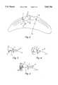
- FIG. 1shows a perspective view of an embodiment of the surgical implant according to the invention
- FIGS. 2-5show sectional views of the meniscus, in which one or several surgical implants according to the invention have been installed.
- the implants according to the inventionare manufactured of polymeric self-reinforced absorbable composites (SRAC) which have been described in several publications, including U.S. Pat. No. 4,743,257 and Finnish Pat. Appl. No. 870111.
- SRACpolymeric self-reinforced absorbable composites
- the bone fracture fixation devices manufactured of polymeric SRAChave been known earlier.
- the SRAC materialshave not been previously known.
- the inventorshave unexpectedly found that regardless of the totally different nature of meniscal tissue (fibrous, soft, tough and elastic) in comparison with bone tissue (hard and brittle), the meniscal repair devices made of SRAC provide good fixation of meniscal lesions.
- SRAC meniscal fixation devicesare rapid and safe to use with a special instrument related to this invention and described in a parallel application, which is of significant benefit for surgical practice.
- Polymeric SRACis the ideal raw material in manufacturing of devices of this invention because of several reasons:
- the strong SRAC devicesmaintain the ruptured meniscal parts in contact with each other during the early period of healing leading to a rapid consolidation of the lesion or rupture in the tissue
- the absorption of SRAC implantguarantees that after absorption there is no risk of implant related long term complications, such as inflammatory reactions or infections which may occur with biostable polymeric implants even years after operation.
- Partially crystalline, absorbable polymers, copolymers or polymer mixtures or alloysare especially suitable raw materials for manufacturing of the implant of this invention.
- suitable polymers that can be used as materials for the implantinclude polymers known from the following publications:
- the implants of the inventioncan be manufactured of the above polymers by applying either one polymer or a suitable polymer alloy or mixture.
- FIG. 1shows a typical surgical implant according to the invention. It is designed to have an arrow shape, and it comprises a body 1 whose one end is formed as a stem 2 and whose other end is formed as a head 3.
- the headcomprises arresting means 5 extending at a section of the body 1.
- the purpose of the stem 2is to stop the implant at the final stage of the installation and to prevent the implant from moving in the direction of installation when it is already in the installed position.
- the arresting means 5are intended to keep the implant installed in the position of use, particularly in the direction opposite to the direction of installation.
- the stem 2protrudes from the outer surface of the body 1 firstly for the purpose of arresting as described above, and secondly for the purpose of providing the impact surface required for the instrument used in the installation of the implant.
- the stem 2is formed of at least one wing or the like 4 extending substantially in the longitudinal direction of the body 1.
- Each wing 4 connected with the stem 2is at one edge 4a attached to the outer surface of the body 1.
- the other edge surface 4b of the wing, attached to the edge 4a in perpendicular directionis designed to be parallel with the back surface 1a of the body 1.
- This back edge surface 4b of the wingis situated essentially in the same plane as the back surface 1a of the body 1 to form the wide impact surface required for the front surface of the instrument.
- the thickness of the wing 4 or the like, i.e. the dimension xdoes not exceed the maximum dimension V of the body 1 in the direction of dimension x.
- the implantcomprises two wings 4 protruding from the body 1 at the stem 2 in two directions.
- the partsprotrude radially in opposite directions as seen in the longitudinal direction of the body, whereby the wings 4 form an integrated plate-like piece having a bulge K at its center formed by the outer surface of body 1 on both sides of the main plane of the plate-like piece.
- each wing 4has a substantially quadrangular form, preferably a rectangular or trapezoid form, whereby in the direction of installation of the wing 4, the third edge 4c is substantially transverse or perpendicular to the longitudinal direction of the body 1 and thus provides an effective arresting impact at the end of the installation operation and keeps the implant in its position.
- the body 1can have a polygonal or curved cross-section, but in an advantageous embodiment, the cross-sectional form of the body is a circle with a substantially even thickness, as shown in FIG. 1.
- the thickness x of the wingcan thus be smaller than the diameter V of the circular form.
- the dimension x of the wingcan have an even thickness or it can taper off or widen from the first edge 4a towards the fourth and outermost edge 4d of the wing 4.
- the arresting means 5which, particularly in combination with the sharp end 3a of the head 3, are formed in such a manner that they do not completely protrude from the outer surface of the body 1. This facilitates the installation of the implant first as it moves in the installation channel of the instrument and further as it penetrates the tissue.
- the arresting means 5are formed as a kind of scutellate structure, for example, in two (or more) subsequent lines or mixed formations at certain distances on the whole perimeter of the body as shown in FIG. 1.
- the arresting means 5 adjacent with the head 3are formed by cuts 6 or the like made in the polymer material of the body 1.
- the cutsseparate part of the material of the body 1 to form barbs or the like, their base parts 5a being connected to the body 1 and their bodies 5b and heads 5c being directed to the stem 2 of the implant.
- the cuts 6 or the likeare formed toward comprise a first, substantially curved section 6a, where the head 5c of the said arresting means 5 is formed, and a second section 6b substantially parallel to the longitudinal direction of the body, where the body 5b of the arresting means 5 is formed.
- the arresting means 5tend to be directed outwards from the body, if the implant is subjected to forces which tend to move it in the direction opposite to the direction of installation.
- the scutellate structure of the arresting meanspositioned in two adjacent lines on the whole perimeter of the body in its longitudinal direction, prevents the movement of the stem in the direction opposite to the direction of installation.
- the cuts 6can be formed by a cutting means also to be directed at an inclined angle inwards the body 1, whereby the material forming the arresting means 5 of the body 1, particularly its head 5c, bends to protrude from the outer surface of the body 1.
- the arresting means 5are thus at least partly formed by working, for example, cutting, the material of the body 1 substantially in the longitudinal direction of the body 1.
- Part of the arresting means 5can naturally be formed for example, of structures known in U.S. Pat. No. 4,873,976.
- FIGS. 2-5show schematically how three implants D of the type illustrated in FIG. 1 are used in fixation of a meniscal lesion L.
- the stems of the implants 2(solid lines) are on the outer (upper) surface of the meniscus.
- the bodies and the heads of the implants(drawn by broken lines)are inside the meniscal tissue.
- FIG. 3shows in a cross-sectional side view in vertical plane in the direction x--x of FIG. 2 how a meniscal repair implant penetrates the lesion L so that its body 1 and head 3 are inside of the meniscal tissue and the stem 2 is at least partially on the surface of the meniscus. It is possible also to trigger the implant totally inside of the meniscal tissue as shown in FIG. 4. In this case, the irritation effect of the implant inside of joint cavity is minimal.
- the head 3can penetrate through the meniscal tissue into the joint capsule NK as shown in FIG. 5.
- the self-reinforced absorbable implants of this inventioncan be manufactured of absorbable polymers, copolymers or polymer mixtures or alloys with several methods. It is possible to use the techniques of U.S. Pat. No. 4,743,257 to sinter in a compression mold absorbable fibers (and possibly additional binding polymer powder) together to create a self-reinforced structure.
- the implants of this inventioncan be molded ready in a single compression molding cycle, or they can be machined at least partially mechanically (and using possible additional heat) after sintering.
- the self-reinforced implants of this inventioncan be manufactured also by machining mechanically (and/or possibly also using heat) from self-reinforced extruded or injection-molded and drawn semifinished products, such as rods and wings described in WO 88/05312.
- the reinforcing elements of the self-reinforced structureare mainly oriented in the direction of the long axis of the stem of the implant.
- the reinforcement elementscan also turn spirally around the long axis of the implant.
- other different orientations of reinforcement elements in elongated sampleswhich are familiar from composite technology can be applied (see e.g. Engineered Materials Handbook, Volume 1, Composites, ASM International, Metals Park, Ohio 44073 USA, 1988).
- a general feature of self-reinforcement of the implants of this inventionis that an essential part of reinforcing elements is oriented in such a way that they can carry effectively the different loads (such as tensile, bending and shear loads) which are directed to the healing meniscal tissue from the outside (for example, because of the movements of the patient's knee).
- loadssuch as tensile, bending and shear loads
- the meniscal repair implantmay contain one or more bioactive substances, such as antibiotics, chemotherapeutic substances, substances accelerating the healing of the wound, growth hormones and the like.
- bioactive meniscal repair implantsare especially advantageous in surgical use, because they contribute with biochemical, drug and the like, effects to the healing of the lesion in addition to the mechanical supporting effect.
- the self-reinforced materials of the implantstypically have tensile strengths of 100-500 MPa, bending strengths of 100-400 MPa and shear strengths 80-200 of MPa. Additionally, they are usually stiff and tough. These mechanical properties are superior to those of non-reinforced absorbable polymers which typically show strengths between 40 and 100 MPa and are additionally either very flexible or brittle (see e.g. S. Vainionpaa, P. Rokkanen and P. Tormala, "Surgical Applications of Biodegradable Polymers in Human Tissues", Progr. Polym. Sci. 14 (1989), pp. 679-716).
- the implants of the present invention as well as the instrumentsare sterilized by any of the well known sterilization techniques generally depending on the type of material used in manufacture of the implant or the instrument or its components. Suitable sterilization techniques include heat or steam sterilization, radiation sterilization such as cobalt 60 irradiation or electron beams, ethylene oxide sterilization, and the like.
- Moldswere constructed for transfer molding or for compression molding (sintering) and for injection molding of meniscal repair implants with the geometry corresponding substantially to that of the device in FIG. 1.
- the dimensions of the manufactured implantswere: the length of the arresting means 5 connected with the head 3 in two subsequent lines: about 2.0 mm; the thickness of the cylindrical body 1: 1.4 mm; the dimension x of the wing 4: 1.1 mm; the edge 4a: 3 mm and edges 4b, 4c: 1.5 mm.
- the total length of the implantswas 15 mm.
- the cuts required for formation of the arresting means 5were made at a separate stage after the compression stage.
- the implants of the inventionwere manufactured by transfer molding in the following manner.
- the melt of glycolide/lactide (90/10) copolymer(internal viscosity
- the melt-fiber mixturewas injected rapidly into the implant mold which was cooled rapidly.
- the fiber content of the implantswas 30% (w/w).
- the bending strength of these self-reinforced absorbable implantswas 140 MPa.
- the bending strength of corresponding non-reinforced devices manufactured from glycolide/lactide copolymer meltwas 80 MPa.
- Example 1The mold of Example 1 was used to manufacture implants by compression molding.
- Glycolide/lactide copolymer sutures(Vicryl R ) (size 2 USP) were heated in evacuated mold to 185° C. for about 4 min which caused the partial melting of fiber units of sutures.
- the materialwas compression molded to a device of FIG. 1a with a pressure of 2000 bar, and it was cooled rapidly.
- the shear strength of these self-reinforced implantswas 120 MPa.
- the shear strength of corresponding non-reinforced devices manufactured from glycolide/lactide copolymer meltwas 70 MPa.
- Example 1The mold of Example 1 was used to manufacture the devices by compression molding.
- Polyglycolide sutures(Dexon R ) (size 2 USP) were heated in evacuated mold to 224° C. during about 5 min with a pressure of 2000 bar.
- the softened fiber materialwas fused partially together, and it filled the mold cavity shaped like the implant of FIG. 1.
- the moldwas cooled rapidly, and the implant was removed.
- the tensile strength of these self-reinforced absorbable deviceswas 160 MPa.
- the tensile strength of corresponding non-reinforced implants manufactured from polyglycolide meltwas 80 MPa.
- Isomers of absorbable polymerscan be applied to manufacture implants of the invention.
- isomers of polylactidesuch as poly-L-lactide (PLLA), poly-D-lactide (PDLA), poly-DL-lactide (PDLLA) and copolymers of L-lactide and D-lactide which contain different amounts of L-units and D-units can be used as such in fiber form, or mixtures of their fibers can be used to sinter the implants.
- PLLAis a partially crystalline polymer with a melting point of about 180° C.
- the isomers containing D-unitshave lower melting points.
- self-reinforced implantscan be manufactured of polylactide isomers using fibers of PLLA or of copolymer with low content of D-units as reinforcement fibers and a copolymer with higher content of D-units as matrix.
- the self-reinforced materialscan be manufactured of these materials, for example, by combining isomer matrix and fibers, thread or corresponding reinforcement structures to each other by means of heat and pressure.
- the fiber content of self-reinforced implantswas 50%, and their bending strength was 200 MPa.
- Bending strengths of non-reinforced rods manufactured from polymer meltswere for PLLA 600 MPa and for poly-DL-lactide 50 MPa.
- the softened fiber materialwas partially fused together filling the mold, and the mold was cooled to room temperature rapidly.
- the tensile strength of these self-reinforced absorbable implantswas 120 MPa.
- the tensile strength of corresponding non-reinforced implants manufactured from poly-L-lactide meltwas 50 MPa.
- Poly- ⁇ -hydroxybutyric acid fibers(diameter 100 ⁇ m) were heated in pressurized mold of Example 1 to 175° C. for 5 min with a pressure of 2000 bar. The softened fiber material was partially fused together, and the mold was rapidly cooled to room temperature. The bending strength of these self-reinforced absorbable composite devices was 100 MPa. The bending strength of corresponding non-reinforced implants manufactured of poly- ⁇ -hydroxybutyrate acid melt was 40 MPa.
- Polydioxanone sutures(PDS of Ethicon; size 0) were heated in pressurized mold of Example 1 to 103° C. for 6 min with a pressure of 2000 bar. The softened fiber material was partially fused together, and the mold was rapidly cooled to room temperature. The shear strength of these self-reinforced absorbable composite implants was 140 MPa. The shear strength of corresponding non-reinforced implants manufactured of polydioxanone melt was 50 MPa.
- Glycolide/lactide (PGA/PLA) copolymer sutures(Vicryl R ; size 1) containing 30% (w/w) of polyglycolide sutures (Dexon R ; size 2) were heated in mold of Example 1 in vacuum at 180° C. for 6 min, which caused the partial melting of glycolide/lactide fiber units of Vicryl sutures. The material was compression molded to implants with a pressure of 2000 bar, and it was rapidly cooled.
- a hybrid composite rod which was composed of self-reinforced glycolide/lactide material into which were embedded polyglycolide sutureswas obtained.
- the bending strength of hybride composite materialwas 250 MPa.
- the bending strength of corresponding composite manufactured from glycolide/lactide copolymer melt reinforced with 30% (w/w) of polyglycolide sutureswas 200 MPa.
- Monofilament sutures(size 0) manufactured of polyglycolide/trimethylenecarbonate copolymer (Maxon of Davis+Geck) were heated in a pressurized mold of Example 1 to 225° C. for 4 min, applying a pressure of 2000 bar during the last 1 min. The sutures were partially fused together, and the mold was rapidly cooled to room temperature. Self-reinforced absorbable devices with the shear strength of 130 MPa were obtained. The shear strength of corresponding non-reinforced implants manufactured of totally melted Maxon sutures was 60 MPa.
- the rodswere drawn to the drawing ratio 10, simultaneously raising the temperature of the rods to 90° . . . 130° C.
- the self-reinforced (fibrillated) structure of the drawn rodswas seen microscopically.
- the implants manufactured by the method described aboveshowed bending strength of 250 MPa and shear strength of 170 MPa.
- Polyglycolide(Mw about 50,000) was extruded to continuous rods with a diameter of 4.4 mm.
- the rodswere drawn at 160° C. to self-reinforced rods with a diameter of 1.3 mm.
- the continuous rodswere cut to pieces of about 21 mm, to which stems were formed in molds of Example 11 at 230° C. and arresting means were worked in connection with the head.
- These implants of the inventionshowed bending strength of 360 MPa and shear strength of 250 MPa.
- Monofilament sutures(size 2; Maxon of Davis+Geck) manufactured of polyglycolide/trimethylenecarbonate copolymer were cut to 5-10 mm pieces and melted and extruded with a self-made piston extruder to a continuous rod with a diameter of 4.4 mm.
- the rodwas drawn at 140° . . . 195° C. to a self-reinforced rod with a diameter of 1.1 mm.
- the strength valueswere measured at room temperature (22° . . . 23° C.) with a mechanical testing machine (by J.J. Lloyd Instruments, England).
- Poly-L-lactide (Mw ca. 100,000) and poly-D-lactide (Mw about 100,000)were blended in the melt state (blending ratio 1:1) in an extruder.
- This alloywas extruded to a rod with a 4.4 mm diameter and solidified to a stereocomplex material which exhibited a melting point of 220° C.
- the rodwas heat treated at 180° C. and drawn to self-reinforced rod with a diameter of 1.1 mm.
- the self-reinforced rodwas cut to pieces of 21 mm. These were upset into the arrow-shaped implants of Example 13 at 220° C. using the molds of Example 13. These implants showed the bending strength of 280 MPa.
- the non-reinforced injection-molded rodsshowed the bending strength of 120 MPa.
- the poly-L-lactide and poly-D-lactide blend of Example 14was extruded to 0.8 mm thick monofilaments which were drawn to fibers with a diameter of 100 ⁇ m at 110° C.
- the stereocomplex fiberswere sintered into the devices of the invention in a compression mold by heating them for 5 min from 23° C. to 222° C. at a pressure of 2000 bar.
- These self-reinforced polylactide stereocomplex implantsshowed the shear strength of 220 MPa.
- the corresponding implants manufactured by injection molding of the same poly-L-lactide and poly-D-lactide meltshowed the shear strength of 95 MPa.
- Comparative triggering testswere made with injection-molded, non-reinforced implants manufactured according to Examples 1-10. Twenty-one of the implants buckled and/or broke (depending on the raw material) during triggering.
- Implants of the invention according to the dimensions of Example 1were used in experimental fixation of surgically generated meniscal lesions in sheep.
- the following self-reinforced (SR) implantswere used: SR-PGA implants of Example 3, SR-PGA implants of Example 4, SR-PLLA implants of Example 6, SR-PGA/PLA implants of Example 9, SR-PLLA implants of Example 11, SR-PGA implants of Example 12, and polylactide-stereo-complex implants of Example 15.
- Two animalswere operated in each case. The devices were applied through an arthrotomy under direct visualization in surgically generated meniscal lesions by triggering them with the instrument of the invention into the meniscal tissue. No fracture, buckling or unfavorable migration of implants occurred during operations. Two control animals were used where lesion was not repaired.
Landscapes
- Health & Medical Sciences (AREA)
- Surgery (AREA)
- Life Sciences & Earth Sciences (AREA)
- Animal Behavior & Ethology (AREA)
- Veterinary Medicine (AREA)
- Engineering & Computer Science (AREA)
- Heart & Thoracic Surgery (AREA)
- Public Health (AREA)
- General Health & Medical Sciences (AREA)
- Biomedical Technology (AREA)
- Molecular Biology (AREA)
- Medical Informatics (AREA)
- Nuclear Medicine, Radiotherapy & Molecular Imaging (AREA)
- Chemical & Material Sciences (AREA)
- Composite Materials (AREA)
- Materials Engineering (AREA)
- Vascular Medicine (AREA)
- Epidemiology (AREA)
- Prostheses (AREA)
- Materials For Medical Uses (AREA)
- Surgical Instruments (AREA)
Abstract
Description
Claims (20)
Applications Claiming Priority (3)
| Application Number | Priority Date | Filing Date | Title |
|---|---|---|---|
| FI920305 | 1992-01-24 | ||
| FI920305AFI95537C (en) | 1992-01-24 | 1992-01-24 | Surgical implant |
| PCT/FI1993/000014WO1993014705A1 (en) | 1992-01-24 | 1993-01-18 | Surgical implant |
Publications (1)
| Publication Number | Publication Date |
|---|---|
| US5562704Atrue US5562704A (en) | 1996-10-08 |
Family
ID=8534177
Family Applications (1)
| Application Number | Title | Priority Date | Filing Date |
|---|---|---|---|
| US08/256,808Expired - LifetimeUS5562704A (en) | 1992-01-24 | 1993-01-18 | Surgical implant |
Country Status (11)
| Country | Link |
|---|---|
| US (1) | US5562704A (en) |
| EP (1) | EP0623005B1 (en) |
| JP (1) | JP2960166B2 (en) |
| AT (1) | ATE178772T1 (en) |
| AU (1) | AU663356B2 (en) |
| CA (1) | CA2127556C (en) |
| DE (1) | DE69324475T2 (en) |
| DK (1) | DK0623005T3 (en) |
| ES (1) | ES2129514T3 (en) |
| FI (1) | FI95537C (en) |
| WO (1) | WO1993014705A1 (en) |
Cited By (61)
| Publication number | Priority date | Publication date | Assignee | Title |
|---|---|---|---|---|
| WO1997018761A1 (en)* | 1995-11-17 | 1997-05-29 | Innovasive Devices, Inc. | Surgical fastening system and method for using the same |
| US5702656A (en)* | 1995-06-07 | 1997-12-30 | United States Surgical Corporation | Process for making polymeric articles |
| US5843084A (en)* | 1995-11-17 | 1998-12-01 | Innovasive Devices, Inc. | Surgical fastening system and method for using the same |
| WO1999001071A1 (en) | 1997-07-02 | 1999-01-14 | Bionx Implants Oy | Surgical fastener for tissue treatment |
| WO1999049792A1 (en) | 1998-04-01 | 1999-10-07 | Bionx Implants Oy | Bioabsorbable surgical fastener for tissue treatment |
| US5993475A (en)* | 1998-04-22 | 1999-11-30 | Bristol-Myers Squibb Co. | Tissue repair device |
| US6042584A (en)* | 1998-12-04 | 2000-03-28 | Pierson, Iii; Raymond H. | Bone depth resection guide and method |
| WO2000030552A1 (en)* | 1998-11-25 | 2000-06-02 | Biocomposites Limited | A surgical device for closing tissue |
| US6113640A (en)* | 1997-06-11 | 2000-09-05 | Bionx Implants Oy | Reconstructive bioabsorbable joint prosthesis |
| US6146387A (en)* | 1998-08-26 | 2000-11-14 | Linvatec Corporation | Cannulated tissue anchor system |
| US6200323B1 (en) | 1998-12-04 | 2001-03-13 | Pierson, Iii Raymond H. | Bone depth resection guide and method |
| USD443058S1 (en) | 1999-09-17 | 2001-05-29 | Genzyme Corporation | Curved medical device for the application of a tack to the body of a patient |
| USD447565S1 (en) | 1999-09-17 | 2001-09-04 | Genzyme Corporation | Straight medical device for the application of a tack to the body of a patient |
| US6302885B1 (en)* | 1998-01-15 | 2001-10-16 | Holger K. Essiger | Bone nail |
| US6306156B1 (en) | 1997-11-20 | 2001-10-23 | Ron Clark | Meniscus repair anchor system |
| US6322563B1 (en) | 1999-09-17 | 2001-11-27 | Genzyme Corporation | Small tissue and membrane fixation apparatus and methods for use thereof |
| US20020068947A1 (en)* | 2000-10-19 | 2002-06-06 | Kuhns Jesse J. | Surgical instrument having a fastener delivery mechanism |
| US6406498B1 (en) | 1998-09-04 | 2002-06-18 | Bionx Implants Oy | Bioactive, bioabsorbable surgical composite material |
| US6425900B1 (en)* | 2000-10-19 | 2002-07-30 | Ethicon Endo-Surgery | Method for attaching hernia mesh |
| US6447524B1 (en)* | 2000-10-19 | 2002-09-10 | Ethicon Endo-Surgery, Inc. | Fastener for hernia mesh fixation |
| US20020183751A1 (en)* | 2000-04-04 | 2002-12-05 | Justin Daniel F. | Orthopedic screw and method |
| US6579533B1 (en) | 1999-11-30 | 2003-06-17 | Bioasborbable Concepts, Ltd. | Bioabsorbable drug delivery system for local treatment and prevention of infections |
| US20030167072A1 (en)* | 1999-08-25 | 2003-09-04 | Oberlander Michael A. | Multi-anchor suture |
| US6623492B1 (en) | 2000-01-25 | 2003-09-23 | Smith & Nephew, Inc. | Tissue fastener |
| US20030199877A1 (en)* | 2000-09-07 | 2003-10-23 | Peter Steiger | Device for fixing surgical implants |
| US20040009228A1 (en)* | 1999-11-30 | 2004-01-15 | Pertti Tormala | Bioabsorbable drug delivery system for local treatment and prevention of infections |
| US6679890B2 (en) | 2001-08-28 | 2004-01-20 | Joseph Y. Margulies | Method and apparatus for augmentation of the femoral neck |
| WO2004062459A2 (en) | 2003-01-09 | 2004-07-29 | Linvatec Biomaterials Oy | Suture anchor device and method of using |
| US6911037B2 (en) | 1999-09-07 | 2005-06-28 | Ev3, Inc. | Retrievable septal defect closure device |
| US20050187555A1 (en)* | 2004-02-24 | 2005-08-25 | Biedermann Motech Gmbh | Bone anchoring element |
| WO2005079388A3 (en)* | 2004-02-13 | 2006-04-06 | Univ Cincinnati | A coupling device enabled by mechanical continuity of cellular scaffolding across tissue boundaries |
| US20060129152A1 (en)* | 2004-12-10 | 2006-06-15 | Shipp John I | Absorbable Anchor for Hernia Mesh Fixation |
| EP1749490A1 (en) | 2005-08-05 | 2007-02-07 | BIEDERMANN MOTECH GmbH | Bone anchoring element |
| US20070037096A1 (en)* | 2003-09-30 | 2007-02-15 | Dai Nippon Printing Co. Ltd. | Photo radical generator, photo sensitive resin composition and article |
| US20070198018A1 (en)* | 2006-02-23 | 2007-08-23 | Lutz Biedermann | Bone anchoring device |
| US7288105B2 (en) | 2001-08-01 | 2007-10-30 | Ev3 Endovascular, Inc. | Tissue opening occluder |
| US20070276462A1 (en)* | 2000-04-29 | 2007-11-29 | Endovascular Technologies, Inc. | Modular graft component junctions |
| US20070299449A1 (en)* | 2006-06-06 | 2007-12-27 | Bioretec Oy | Bone fixation device |
| WO2007013967A3 (en)* | 2005-07-21 | 2008-10-16 | Rayonier Trs Holdings Inc | Acquisition fiber in sheet form with low degree of yellowing and low odor |
| US7455674B2 (en) | 2002-01-31 | 2008-11-25 | Smith & Nephew Plc | High strength bioresorbables containing poly-glycolic acid |
| US7524891B2 (en) | 2001-07-04 | 2009-04-28 | Smith & Nephew Plc | Biodegradable polymer systems |
| US20090125028A1 (en)* | 2007-11-14 | 2009-05-14 | Jacques Teisen | Hybrid bone fixation element and methods of using the same |
| CN100591297C (en)* | 2005-07-08 | 2010-02-24 | 比德曼莫泰赫有限公司 | Bone anchoring element |
| US20100136648A1 (en)* | 2007-04-18 | 2010-06-03 | Smith & Nephew, Plc | Expansion Moulding of Shape Memory Polymers |
| US20100145448A1 (en)* | 2007-04-19 | 2010-06-10 | Smith & Nephew, Inc. | Graft Fixation |
| US7780700B2 (en) | 2003-02-04 | 2010-08-24 | ev3 Endovascular, Inc | Patent foramen ovale closure system |
| US20110082507A1 (en)* | 2005-05-13 | 2011-04-07 | Kaj Klaue | Osteosynthesis Device |
| US20110144751A1 (en)* | 2007-04-19 | 2011-06-16 | Smith & Nephew, Inc | Multi-Modal Shape Memory Polymers |
| US20110178534A1 (en)* | 2010-01-20 | 2011-07-21 | Whitman Michael P | Tissue repair implant and delivery device and method |
| US20110218191A1 (en)* | 2010-03-03 | 2011-09-08 | Boehringer Ingelheim Vetmedica Gmbh | Use of meloxicam for the long term-treatment of kidney disorders in cats |
| KR101145415B1 (en) | 2005-07-08 | 2012-05-15 | 비이더만 모테크 게엠베하 & 코. 카게 | Bone Anchoring Element |
| US8722783B2 (en) | 2006-11-30 | 2014-05-13 | Smith & Nephew, Inc. | Fiber reinforced composite material |
| US20140199364A1 (en)* | 2009-01-21 | 2014-07-17 | Maria Palasis | Drug loaded fibers |
| US9120919B2 (en) | 2003-12-23 | 2015-09-01 | Smith & Nephew, Inc. | Tunable segmented polyacetal |
| US9155578B2 (en) | 2012-02-28 | 2015-10-13 | DePuy Synthes Products, Inc. | Expandable fastener |
| US20170258557A1 (en)* | 2009-08-06 | 2017-09-14 | Sue S. Lee | Dental Implant |
| US9980708B2 (en) | 2010-01-20 | 2018-05-29 | Micro Interventional Devices, Inc. | Tissue closure device and method |
| US10058314B2 (en) | 2010-01-20 | 2018-08-28 | Micro Interventional Devices, Inc. | Tissue closure device and method |
| US10743854B2 (en) | 2010-01-20 | 2020-08-18 | Micro Interventional Devices, Inc. | Tissue closure device and method |
| US10959840B2 (en) | 2010-01-20 | 2021-03-30 | Micro Interventional Devices, Inc. | Systems and methods for affixing a prosthesis to tissue |
| US20220039793A1 (en)* | 2017-03-16 | 2022-02-10 | Cannuflow, Inc. | System And Method For Fixing Sheet-Like Materials To A Target Tissue |
Families Citing this family (63)
| Publication number | Priority date | Publication date | Assignee | Title |
|---|---|---|---|---|
| FI98136C (en) | 1995-09-27 | 1997-04-25 | Biocon Oy | A tissue-soluble material and process for its manufacture |
| US6436124B1 (en) | 1996-12-19 | 2002-08-20 | Bionx Implants Oy | Suture anchor |
| US20030097180A1 (en) | 2001-11-20 | 2003-05-22 | Pertti Tormala | Joint prosthesis |
| US7713285B1 (en) | 2003-07-02 | 2010-05-11 | Biomet Sports Medicine, Llc | Method and apparatus for suture anchors with a vertical eyelet |
| US7217279B2 (en)* | 2003-11-14 | 2007-05-15 | Ethicon, Inc. | Suture loop anchor |
| US7608092B1 (en) | 2004-02-20 | 2009-10-27 | Biomet Sports Medicince, LLC | Method and apparatus for performing meniscus repair |
| US8109965B2 (en) | 2004-06-09 | 2012-02-07 | Biomet Sports Medicine, LLP | Method and apparatus for soft tissue fixation |
| US7500983B1 (en) | 2004-06-09 | 2009-03-10 | Biomet Sports Medicine, Llc | Apparatus for soft tissue attachment |
| US7909851B2 (en) | 2006-02-03 | 2011-03-22 | Biomet Sports Medicine, Llc | Soft tissue repair device and associated methods |
| US8840645B2 (en) | 2004-11-05 | 2014-09-23 | Biomet Sports Medicine, Llc | Method and apparatus for coupling soft tissue to a bone |
| US7749250B2 (en) | 2006-02-03 | 2010-07-06 | Biomet Sports Medicine, Llc | Soft tissue repair assembly and associated method |
| US8118836B2 (en) | 2004-11-05 | 2012-02-21 | Biomet Sports Medicine, Llc | Method and apparatus for coupling soft tissue to a bone |
| US7905904B2 (en) | 2006-02-03 | 2011-03-15 | Biomet Sports Medicine, Llc | Soft tissue repair device and associated methods |
| US8088130B2 (en) | 2006-02-03 | 2012-01-03 | Biomet Sports Medicine, Llc | Method and apparatus for coupling soft tissue to a bone |
| US8128658B2 (en) | 2004-11-05 | 2012-03-06 | Biomet Sports Medicine, Llc | Method and apparatus for coupling soft tissue to bone |
| US8137382B2 (en) | 2004-11-05 | 2012-03-20 | Biomet Sports Medicine, Llc | Method and apparatus for coupling anatomical features |
| US7658751B2 (en) | 2006-09-29 | 2010-02-09 | Biomet Sports Medicine, Llc | Method for implanting soft tissue |
| US9017381B2 (en) | 2007-04-10 | 2015-04-28 | Biomet Sports Medicine, Llc | Adjustable knotless loops |
| US8361113B2 (en) | 2006-02-03 | 2013-01-29 | Biomet Sports Medicine, Llc | Method and apparatus for coupling soft tissue to a bone |
| US8298262B2 (en) | 2006-02-03 | 2012-10-30 | Biomet Sports Medicine, Llc | Method for tissue fixation |
| US9801708B2 (en) | 2004-11-05 | 2017-10-31 | Biomet Sports Medicine, Llc | Method and apparatus for coupling soft tissue to a bone |
| US8303604B2 (en) | 2004-11-05 | 2012-11-06 | Biomet Sports Medicine, Llc | Soft tissue repair device and method |
| US8998949B2 (en) | 2004-11-09 | 2015-04-07 | Biomet Sports Medicine, Llc | Soft tissue conduit device |
| US8968364B2 (en) | 2006-02-03 | 2015-03-03 | Biomet Sports Medicine, Llc | Method and apparatus for fixation of an ACL graft |
| US9078644B2 (en) | 2006-09-29 | 2015-07-14 | Biomet Sports Medicine, Llc | Fracture fixation device |
| US11259792B2 (en) | 2006-02-03 | 2022-03-01 | Biomet Sports Medicine, Llc | Method and apparatus for coupling anatomical features |
| US8506597B2 (en) | 2011-10-25 | 2013-08-13 | Biomet Sports Medicine, Llc | Method and apparatus for interosseous membrane reconstruction |
| US8597327B2 (en) | 2006-02-03 | 2013-12-03 | Biomet Manufacturing, Llc | Method and apparatus for sternal closure |
| US9271713B2 (en) | 2006-02-03 | 2016-03-01 | Biomet Sports Medicine, Llc | Method and apparatus for tensioning a suture |
| US11311287B2 (en) | 2006-02-03 | 2022-04-26 | Biomet Sports Medicine, Llc | Method for tissue fixation |
| US8574235B2 (en) | 2006-02-03 | 2013-11-05 | Biomet Sports Medicine, Llc | Method for trochanteric reattachment |
| US9149267B2 (en) | 2006-02-03 | 2015-10-06 | Biomet Sports Medicine, Llc | Method and apparatus for coupling soft tissue to a bone |
| US8562645B2 (en) | 2006-09-29 | 2013-10-22 | Biomet Sports Medicine, Llc | Method and apparatus for forming a self-locking adjustable loop |
| US8771352B2 (en) | 2011-05-17 | 2014-07-08 | Biomet Sports Medicine, Llc | Method and apparatus for tibial fixation of an ACL graft |
| US8652172B2 (en) | 2006-02-03 | 2014-02-18 | Biomet Sports Medicine, Llc | Flexible anchors for tissue fixation |
| US9538998B2 (en) | 2006-02-03 | 2017-01-10 | Biomet Sports Medicine, Llc | Method and apparatus for fracture fixation |
| US9468433B2 (en) | 2006-02-03 | 2016-10-18 | Biomet Sports Medicine, Llc | Method and apparatus for forming a self-locking adjustable loop |
| US8801783B2 (en) | 2006-09-29 | 2014-08-12 | Biomet Sports Medicine, Llc | Prosthetic ligament system for knee joint |
| US8562647B2 (en) | 2006-09-29 | 2013-10-22 | Biomet Sports Medicine, Llc | Method and apparatus for securing soft tissue to bone |
| US8652171B2 (en) | 2006-02-03 | 2014-02-18 | Biomet Sports Medicine, Llc | Method and apparatus for soft tissue fixation |
| US10517587B2 (en) | 2006-02-03 | 2019-12-31 | Biomet Sports Medicine, Llc | Method and apparatus for forming a self-locking adjustable loop |
| US11259794B2 (en) | 2006-09-29 | 2022-03-01 | Biomet Sports Medicine, Llc | Method for implanting soft tissue |
| US8500818B2 (en) | 2006-09-29 | 2013-08-06 | Biomet Manufacturing, Llc | Knee prosthesis assembly with ligament link |
| US9918826B2 (en) | 2006-09-29 | 2018-03-20 | Biomet Sports Medicine, Llc | Scaffold for spring ligament repair |
| US8672969B2 (en) | 2006-09-29 | 2014-03-18 | Biomet Sports Medicine, Llc | Fracture fixation device |
| US12419632B2 (en) | 2008-08-22 | 2025-09-23 | Biomet Sports Medicine, Llc | Method and apparatus for coupling anatomical features |
| US12245759B2 (en) | 2008-08-22 | 2025-03-11 | Biomet Sports Medicine, Llc | Method and apparatus for coupling soft tissue to bone |
| US8343227B2 (en) | 2009-05-28 | 2013-01-01 | Biomet Manufacturing Corp. | Knee prosthesis assembly with ligament link |
| US12096928B2 (en) | 2009-05-29 | 2024-09-24 | Biomet Sports Medicine, Llc | Method and apparatus for coupling soft tissue to a bone |
| US12329373B2 (en) | 2011-05-02 | 2025-06-17 | Biomet Sports Medicine, Llc | Method and apparatus for soft tissue fixation |
| US9357991B2 (en) | 2011-11-03 | 2016-06-07 | Biomet Sports Medicine, Llc | Method and apparatus for stitching tendons |
| US9370350B2 (en) | 2011-11-10 | 2016-06-21 | Biomet Sports Medicine, Llc | Apparatus for coupling soft tissue to a bone |
| US9314241B2 (en) | 2011-11-10 | 2016-04-19 | Biomet Sports Medicine, Llc | Apparatus for coupling soft tissue to a bone |
| US9381013B2 (en) | 2011-11-10 | 2016-07-05 | Biomet Sports Medicine, Llc | Method for coupling soft tissue to a bone |
| US9259217B2 (en) | 2012-01-03 | 2016-02-16 | Biomet Manufacturing, Llc | Suture Button |
| US9757119B2 (en) | 2013-03-08 | 2017-09-12 | Biomet Sports Medicine, Llc | Visual aid for identifying suture limbs arthroscopically |
| US9918827B2 (en) | 2013-03-14 | 2018-03-20 | Biomet Sports Medicine, Llc | Scaffold for spring ligament repair |
| US10136886B2 (en) | 2013-12-20 | 2018-11-27 | Biomet Sports Medicine, Llc | Knotless soft tissue devices and techniques |
| US9615822B2 (en) | 2014-05-30 | 2017-04-11 | Biomet Sports Medicine, Llc | Insertion tools and method for soft anchor |
| US9700291B2 (en) | 2014-06-03 | 2017-07-11 | Biomet Sports Medicine, Llc | Capsule retractor |
| US10039543B2 (en) | 2014-08-22 | 2018-08-07 | Biomet Sports Medicine, Llc | Non-sliding soft anchor |
| US9955980B2 (en) | 2015-02-24 | 2018-05-01 | Biomet Sports Medicine, Llc | Anatomic soft tissue repair |
| US9974534B2 (en) | 2015-03-31 | 2018-05-22 | Biomet Sports Medicine, Llc | Suture anchor with soft anchor of electrospun fibers |
Citations (2)
| Publication number | Priority date | Publication date | Assignee | Title |
|---|---|---|---|---|
| US4873976A (en)* | 1984-02-28 | 1989-10-17 | Schreiber Saul N | Surgical fasteners and method |
| US5425747A (en)* | 1993-10-12 | 1995-06-20 | Brotz; Gregory R. | Suture |
- 1992
- 1992-01-24FIFI920305Apatent/FI95537C/enactive
- 1993
- 1993-01-18WOPCT/FI1993/000014patent/WO1993014705A1/enactiveIP Right Grant
- 1993-01-18JPJP5512949Apatent/JP2960166B2/ennot_activeExpired - Fee Related
- 1993-01-18EPEP93902269Apatent/EP0623005B1/ennot_activeExpired - Lifetime
- 1993-01-18DEDE69324475Tpatent/DE69324475T2/ennot_activeExpired - Lifetime
- 1993-01-18USUS08/256,808patent/US5562704A/ennot_activeExpired - Lifetime
- 1993-01-18ATAT93902269Tpatent/ATE178772T1/ennot_activeIP Right Cessation
- 1993-01-18CACA002127556Apatent/CA2127556C/ennot_activeExpired - Lifetime
- 1993-01-18ESES93902269Tpatent/ES2129514T3/ennot_activeExpired - Lifetime
- 1993-01-18DKDK93902269Tpatent/DK0623005T3/enactive
- 1993-01-18AUAU33537/93Apatent/AU663356B2/ennot_activeExpired
Patent Citations (2)
| Publication number | Priority date | Publication date | Assignee | Title |
|---|---|---|---|---|
| US4873976A (en)* | 1984-02-28 | 1989-10-17 | Schreiber Saul N | Surgical fasteners and method |
| US5425747A (en)* | 1993-10-12 | 1995-06-20 | Brotz; Gregory R. | Suture |
Cited By (115)
| Publication number | Priority date | Publication date | Assignee | Title |
|---|---|---|---|---|
| US5702656A (en)* | 1995-06-07 | 1997-12-30 | United States Surgical Corporation | Process for making polymeric articles |
| US20020188303A1 (en)* | 1995-11-17 | 2002-12-12 | Hart Rickey D. | Surgical fastening system and method for using the same |
| US5843084A (en)* | 1995-11-17 | 1998-12-01 | Innovasive Devices, Inc. | Surgical fastening system and method for using the same |
| US8192458B2 (en) | 1995-11-17 | 2012-06-05 | Depuy Mitek, Inc. | Surgical fastening system and method for using the same |
| US20100160959A1 (en)* | 1995-11-17 | 2010-06-24 | Depuy Mitek, Inc. | Surgical fastening system and method for using the same |
| US7699870B2 (en) | 1995-11-17 | 2010-04-20 | Ethicon, Inc. | Surgical fastening system and method for using the same |
| US20070073336A1 (en)* | 1995-11-17 | 2007-03-29 | Hart Rickey D | Surgical fastening system and method for using the same |
| WO1997018761A1 (en)* | 1995-11-17 | 1997-05-29 | Innovasive Devices, Inc. | Surgical fastening system and method for using the same |
| US5827298A (en)* | 1995-11-17 | 1998-10-27 | Innovasive Devices, Inc. | Surgical fastening system and method for using the same |
| US7105010B2 (en) | 1995-11-17 | 2006-09-12 | Innovasive Devices, Inc. | Surgical fastening system |
| US6113640A (en)* | 1997-06-11 | 2000-09-05 | Bionx Implants Oy | Reconstructive bioabsorbable joint prosthesis |
| US6692499B2 (en)* | 1997-07-02 | 2004-02-17 | Linvatec Biomaterials Oy | Surgical fastener for tissue treatment |
| WO1999001071A1 (en) | 1997-07-02 | 1999-01-14 | Bionx Implants Oy | Surgical fastener for tissue treatment |
| US6306156B1 (en) | 1997-11-20 | 2001-10-23 | Ron Clark | Meniscus repair anchor system |
| US6302885B1 (en)* | 1998-01-15 | 2001-10-16 | Holger K. Essiger | Bone nail |
| US6551343B1 (en) | 1998-04-01 | 2003-04-22 | Bionx Implants, Oy | Bioabsorbable surgical fastener for tissue treatment |
| WO1999049792A1 (en) | 1998-04-01 | 1999-10-07 | Bionx Implants Oy | Bioabsorbable surgical fastener for tissue treatment |
| US5993475A (en)* | 1998-04-22 | 1999-11-30 | Bristol-Myers Squibb Co. | Tissue repair device |
| US6346109B1 (en) | 1998-08-26 | 2002-02-12 | Linvatec Corporation | Cannulated tissue anchor system |
| US6280448B1 (en) | 1998-08-26 | 2001-08-28 | Linvatec Corporation | Cannulated tissue anchor system |
| US6146387A (en)* | 1998-08-26 | 2000-11-14 | Linvatec Corporation | Cannulated tissue anchor system |
| US6290702B1 (en) | 1998-08-26 | 2001-09-18 | Linvatec Corporation | Cannulated tissue anchor system |
| US6406498B1 (en) | 1998-09-04 | 2002-06-18 | Bionx Implants Oy | Bioactive, bioabsorbable surgical composite material |
| GB2363990A (en)* | 1998-11-25 | 2002-01-16 | Biocomposites Ltd | A surgical device for closing tissue |
| WO2000030552A1 (en)* | 1998-11-25 | 2000-06-02 | Biocomposites Limited | A surgical device for closing tissue |
| US6042584A (en)* | 1998-12-04 | 2000-03-28 | Pierson, Iii; Raymond H. | Bone depth resection guide and method |
| US6200323B1 (en) | 1998-12-04 | 2001-03-13 | Pierson, Iii Raymond H. | Bone depth resection guide and method |
| US20030167072A1 (en)* | 1999-08-25 | 2003-09-04 | Oberlander Michael A. | Multi-anchor suture |
| US6911037B2 (en) | 1999-09-07 | 2005-06-28 | Ev3, Inc. | Retrievable septal defect closure device |
| US7377936B2 (en) | 1999-09-07 | 2008-05-27 | Ev3, Inc. | Retrievable septal defect closure device |
| USD447565S1 (en) | 1999-09-17 | 2001-09-04 | Genzyme Corporation | Straight medical device for the application of a tack to the body of a patient |
| USD443058S1 (en) | 1999-09-17 | 2001-05-29 | Genzyme Corporation | Curved medical device for the application of a tack to the body of a patient |
| US6322563B1 (en) | 1999-09-17 | 2001-11-27 | Genzyme Corporation | Small tissue and membrane fixation apparatus and methods for use thereof |
| US6579533B1 (en) | 1999-11-30 | 2003-06-17 | Bioasborbable Concepts, Ltd. | Bioabsorbable drug delivery system for local treatment and prevention of infections |
| US20040009228A1 (en)* | 1999-11-30 | 2004-01-15 | Pertti Tormala | Bioabsorbable drug delivery system for local treatment and prevention of infections |
| US6623492B1 (en) | 2000-01-25 | 2003-09-23 | Smith & Nephew, Inc. | Tissue fastener |
| US7578836B2 (en) | 2000-04-04 | 2009-08-25 | Depuy Mitek | Orthopedic screw and method |
| US6527777B2 (en) | 2000-04-04 | 2003-03-04 | Ethicon, Inc. | Device for repairing a soft-tissue tear and method |
| US6989014B2 (en) | 2000-04-04 | 2006-01-24 | Ethicon, Inc. | Orthopedic screw and method |
| US20020183751A1 (en)* | 2000-04-04 | 2002-12-05 | Justin Daniel F. | Orthopedic screw and method |
| US20060122612A1 (en)* | 2000-04-04 | 2006-06-08 | Justin Daniel F | Orthopedic screw and method |
| US20070276462A1 (en)* | 2000-04-29 | 2007-11-29 | Endovascular Technologies, Inc. | Modular graft component junctions |
| US20030199877A1 (en)* | 2000-09-07 | 2003-10-23 | Peter Steiger | Device for fixing surgical implants |
| US20080045978A1 (en)* | 2000-10-19 | 2008-02-21 | Kuhns Jesse J | Method For Delivering a Plurality of Fasteners |
| US20020068947A1 (en)* | 2000-10-19 | 2002-06-06 | Kuhns Jesse J. | Surgical instrument having a fastener delivery mechanism |
| US7485124B2 (en) | 2000-10-19 | 2009-02-03 | Ethicon Endo-Surgery, Inc. | Surgical instrument having a fastener delivery mechanism |
| US6447524B1 (en)* | 2000-10-19 | 2002-09-10 | Ethicon Endo-Surgery, Inc. | Fastener for hernia mesh fixation |
| US6425900B1 (en)* | 2000-10-19 | 2002-07-30 | Ethicon Endo-Surgery | Method for attaching hernia mesh |
| US7905893B2 (en) | 2000-10-19 | 2011-03-15 | Ethicon Endo-Surgery, Inc. | Method for delivering a plurality of fasteners |
| US20080243143A1 (en)* | 2000-10-19 | 2008-10-02 | Kuhns Jesse J | Surgical instrument having a fastener delivery mechanism |
| US7524891B2 (en) | 2001-07-04 | 2009-04-28 | Smith & Nephew Plc | Biodegradable polymer systems |
| US7887562B2 (en) | 2001-08-01 | 2011-02-15 | Ev3 Endovascular, Inc. | Tissue opening occluder |
| US7288105B2 (en) | 2001-08-01 | 2007-10-30 | Ev3 Endovascular, Inc. | Tissue opening occluder |
| US7582103B2 (en) | 2001-08-01 | 2009-09-01 | Ev3 Endovascular, Inc. | Tissue opening occluder |
| US6679890B2 (en) | 2001-08-28 | 2004-01-20 | Joseph Y. Margulies | Method and apparatus for augmentation of the femoral neck |
| US7455674B2 (en) | 2002-01-31 | 2008-11-25 | Smith & Nephew Plc | High strength bioresorbables containing poly-glycolic acid |
| WO2004062459A2 (en) | 2003-01-09 | 2004-07-29 | Linvatec Biomaterials Oy | Suture anchor device and method of using |
| US7780700B2 (en) | 2003-02-04 | 2010-08-24 | ev3 Endovascular, Inc | Patent foramen ovale closure system |
| US20070037096A1 (en)* | 2003-09-30 | 2007-02-15 | Dai Nippon Printing Co. Ltd. | Photo radical generator, photo sensitive resin composition and article |
| US9120919B2 (en) | 2003-12-23 | 2015-09-01 | Smith & Nephew, Inc. | Tunable segmented polyacetal |
| WO2005079388A3 (en)* | 2004-02-13 | 2006-04-06 | Univ Cincinnati | A coupling device enabled by mechanical continuity of cellular scaffolding across tissue boundaries |
| KR100794735B1 (en) | 2004-02-24 | 2008-01-15 | 비이더만 모테크 게엠베하 | Bone fixation member |
| US9326804B2 (en)* | 2004-02-24 | 2016-05-03 | Biedermann Technologies Gmbh & Co. Kg | Bone anchoring element |
| US20050187555A1 (en)* | 2004-02-24 | 2005-08-25 | Biedermann Motech Gmbh | Bone anchoring element |
| EP1568329A1 (en)* | 2004-02-24 | 2005-08-31 | Biedermann Motech GmbH | Bone-anchoring element |
| US10905482B2 (en) | 2004-02-24 | 2021-02-02 | Biedermann Technologies Gmbh & Co. Kg | Bone anchoring element |
| US9861412B2 (en) | 2004-02-24 | 2018-01-09 | Biedermann Technologies Gmbh & Co. Kg | Bone anchoring element |
| US20060129152A1 (en)* | 2004-12-10 | 2006-06-15 | Shipp John I | Absorbable Anchor for Hernia Mesh Fixation |
| US9480508B2 (en)* | 2005-05-13 | 2016-11-01 | Kaj Klaue | Osteosynthesis device |
| US20110082507A1 (en)* | 2005-05-13 | 2011-04-07 | Kaj Klaue | Osteosynthesis Device |
| US8292932B2 (en) | 2005-07-08 | 2012-10-23 | Biedermann Technologies Gmbh & Co. Kg | Bone anchoring element |
| CN100591297C (en)* | 2005-07-08 | 2010-02-24 | 比德曼莫泰赫有限公司 | Bone anchoring element |
| KR101145415B1 (en) | 2005-07-08 | 2012-05-15 | 비이더만 모테크 게엠베하 & 코. 카게 | Bone Anchoring Element |
| US8845702B2 (en) | 2005-07-08 | 2014-09-30 | Biedermann Technologies Gmbh & Co. Kg | Bone anchoring element |
| WO2007013967A3 (en)* | 2005-07-21 | 2008-10-16 | Rayonier Trs Holdings Inc | Acquisition fiber in sheet form with low degree of yellowing and low odor |
| US20110093019A1 (en)* | 2005-08-05 | 2011-04-21 | Biedermann Motech Gmbh | Bone Anchoring Element |
| US20070073295A1 (en)* | 2005-08-05 | 2007-03-29 | Lutz Biedermann | Bone anchoring element |
| US8657860B2 (en) | 2005-08-05 | 2014-02-25 | Biedermann Technologies Gmbh & Co. Kg | Bone anchoring element |
| US7879036B2 (en) | 2005-08-05 | 2011-02-01 | Biedermann Motech Gmbh | Bone anchoring element |
| EP1749490A1 (en) | 2005-08-05 | 2007-02-07 | BIEDERMANN MOTECH GmbH | Bone anchoring element |
| US20070198018A1 (en)* | 2006-02-23 | 2007-08-23 | Lutz Biedermann | Bone anchoring device |
| EP1825826A1 (en) | 2006-02-23 | 2007-08-29 | BIEDERMANN MOTECH GmbH | Bone anchoring device |
| US8486121B2 (en) | 2006-02-23 | 2013-07-16 | Biedermann Technologies Gmbh & Co. Kg | Bone anchoring device |
| US8080044B2 (en) | 2006-02-23 | 2011-12-20 | Biedermann Motech Gmbh & Co. Kg | Bone anchoring device |
| US9078714B2 (en) | 2006-06-06 | 2015-07-14 | Bioretec Oy | Bone fixation device |
| US20070299449A1 (en)* | 2006-06-06 | 2007-12-27 | Bioretec Oy | Bone fixation device |
| EP1864616B2 (en)† | 2006-06-06 | 2018-04-11 | Bioretec Oy | Method for producing a bone fixation device |
| US8722783B2 (en) | 2006-11-30 | 2014-05-13 | Smith & Nephew, Inc. | Fiber reinforced composite material |
| US20100136648A1 (en)* | 2007-04-18 | 2010-06-03 | Smith & Nephew, Plc | Expansion Moulding of Shape Memory Polymers |
| US9815240B2 (en) | 2007-04-18 | 2017-11-14 | Smith & Nephew, Inc. | Expansion moulding of shape memory polymers |
| US20100145448A1 (en)* | 2007-04-19 | 2010-06-10 | Smith & Nephew, Inc. | Graft Fixation |
| US9000066B2 (en) | 2007-04-19 | 2015-04-07 | Smith & Nephew, Inc. | Multi-modal shape memory polymers |
| US20110144751A1 (en)* | 2007-04-19 | 2011-06-16 | Smith & Nephew, Inc | Multi-Modal Shape Memory Polymers |
| US9770534B2 (en) | 2007-04-19 | 2017-09-26 | Smith & Nephew, Inc. | Graft fixation |
| US9308293B2 (en) | 2007-04-19 | 2016-04-12 | Smith & Nephew, Inc. | Multi-modal shape memory polymers |
| US8556949B2 (en) | 2007-11-14 | 2013-10-15 | DePuy Synthes Products, LLC | Hybrid bone fixation element and methods of using the same |
| US20090125028A1 (en)* | 2007-11-14 | 2009-05-14 | Jacques Teisen | Hybrid bone fixation element and methods of using the same |
| US9510877B2 (en) | 2007-11-14 | 2016-12-06 | DePuy Synthes Products, Inc. | Hybrid bone fixation element and methods of using the same |
| US20140199364A1 (en)* | 2009-01-21 | 2014-07-17 | Maria Palasis | Drug loaded fibers |
| US20170258557A1 (en)* | 2009-08-06 | 2017-09-14 | Sue S. Lee | Dental Implant |
| US10058314B2 (en) | 2010-01-20 | 2018-08-28 | Micro Interventional Devices, Inc. | Tissue closure device and method |
| WO2011091184A1 (en)* | 2010-01-20 | 2011-07-28 | New Hope Ventures, Lp | Tissue repair implant and delivery device and method |
| US12268595B2 (en) | 2010-01-20 | 2025-04-08 | Micro Interventional Devices, Inc. | Systems and methods for affixing a prosthesis to tissue |
| US10959840B2 (en) | 2010-01-20 | 2021-03-30 | Micro Interventional Devices, Inc. | Systems and methods for affixing a prosthesis to tissue |
| US9138211B2 (en) | 2010-01-20 | 2015-09-22 | Micro Interventional Devices, Inc. | Tissue repair implant and delivery device and method |
| US8764795B2 (en) | 2010-01-20 | 2014-07-01 | Micro Interventional Devices, Inc. | Tissue closure device and method |
| US20110178534A1 (en)* | 2010-01-20 | 2011-07-21 | Whitman Michael P | Tissue repair implant and delivery device and method |
| US9427220B2 (en) | 2010-01-20 | 2016-08-30 | Micro Interventional Devices, Inc. | Tissue repair implant and delivery device and method |
| US9980708B2 (en) | 2010-01-20 | 2018-05-29 | Micro Interventional Devices, Inc. | Tissue closure device and method |
| US20110178537A1 (en)* | 2010-01-20 | 2011-07-21 | Whitman Michael P | Tissue repair implant and delivery device and method |
| US10743854B2 (en) | 2010-01-20 | 2020-08-18 | Micro Interventional Devices, Inc. | Tissue closure device and method |
| US9050065B2 (en) | 2010-01-20 | 2015-06-09 | Micro Interventional Devices, Inc. | Tissue repair implant and delivery device and method |
| US20110218191A1 (en)* | 2010-03-03 | 2011-09-08 | Boehringer Ingelheim Vetmedica Gmbh | Use of meloxicam for the long term-treatment of kidney disorders in cats |
| US9155578B2 (en) | 2012-02-28 | 2015-10-13 | DePuy Synthes Products, Inc. | Expandable fastener |
| US20220039793A1 (en)* | 2017-03-16 | 2022-02-10 | Cannuflow, Inc. | System And Method For Fixing Sheet-Like Materials To A Target Tissue |
Also Published As
| Publication number | Publication date |
|---|---|
| AU663356B2 (en) | 1995-10-05 |
| AU3353793A (en) | 1993-09-01 |
| CA2127556A1 (en) | 1993-08-05 |
| JPH07507694A (en) | 1995-08-31 |
| CA2127556C (en) | 2005-03-15 |
| DK0623005T3 (en) | 1999-06-21 |
| FI95537C (en) | 1996-02-26 |
| DE69324475D1 (en) | 1999-05-20 |
| EP0623005A1 (en) | 1994-11-09 |
| ES2129514T3 (en) | 1999-06-16 |
| ATE178772T1 (en) | 1999-04-15 |
| FI920305A7 (en) | 1993-07-25 |
| DE69324475T2 (en) | 1999-09-16 |
| FI920305A0 (en) | 1992-01-24 |
| WO1993014705A1 (en) | 1993-08-05 |
| JP2960166B2 (en) | 1999-10-06 |
| EP0623005B1 (en) | 1999-04-14 |
| FI95537B (en) | 1995-11-15 |
Similar Documents
| Publication | Publication Date | Title |
|---|---|---|
| US5562704A (en) | Surgical implant | |
| US6692499B2 (en) | Surgical fastener for tissue treatment | |
| US6551343B1 (en) | Bioabsorbable surgical fastener for tissue treatment | |
| US6503278B1 (en) | Under tissue conditions degradable material and a method for its manufacturing | |
| US5342395A (en) | Absorbable surgical repair devices | |
| US20020169452A1 (en) | Minimally traumatic surgical device for tissue treatment | |
| US20040138683A1 (en) | Suture arrow device and method of using | |
| US20040138705A1 (en) | Surgical staple for tissue treatment | |
| CN111050677A (en) | Fiber-reinforced biocomposite threaded implants | |
| WO2003043503A2 (en) | Tissue fastener | |
| KR20170098846A (en) | Continuous-fiber reinforced biocomposite medical implants | |
| JP2002510521A (en) | Anatomical fixation implant | |
| AU2003231636B2 (en) | Bioabsorbable Surgical Fastener for Tissue Treatment |
Legal Events
| Date | Code | Title | Description |
|---|---|---|---|
| AS | Assignment | Owner name:BIOCON OY P.O. BOX 3, FINLAND Free format text:ASSIGNMENT OF ASSIGNORS INTEREST;ASSIGNORS:TAMMINMAKI, MARKKU;TORMALA, PERTTI;KRISTENSEN, GERT;AND OTHERS;REEL/FRAME:007195/0736;SIGNING DATES FROM 19940620 TO 19940818 | |
| STCF | Information on status: patent grant | Free format text:PATENTED CASE | |
| REFU | Refund | Free format text:REFUND - PAYMENT OF MAINTENANCE FEE, 4TH YEAR, LARGE ENTITY (ORIGINAL EVENT CODE: R183); ENTITY STATUS OF PATENT OWNER: LARGE ENTITY | |
| FEPP | Fee payment procedure | Free format text:PAT HOLDER CLAIMS SMALL ENTITY STATUS - SMALL BUSINESS (ORIGINAL EVENT CODE: SM02); ENTITY STATUS OF PATENT OWNER: LARGE ENTITY | |
| FPAY | Fee payment | Year of fee payment:4 | |
| AS | Assignment | Owner name:JPMORGAN CHASE BANK, AS ADMINISTRATIVE AGENT, TEXA Free format text:SECURITY INTEREST;ASSIGNOR:LINVATEC BIOMATERIALS, INC.;REEL/FRAME:014250/0780 Effective date:20030326 | |
| FEPP | Fee payment procedure | Free format text:PAT HOLDER NO LONGER CLAIMS SMALL ENTITY STATUS, ENTITY STATUS SET TO UNDISCOUNTED (ORIGINAL EVENT CODE: STOL); ENTITY STATUS OF PATENT OWNER: LARGE ENTITY | |
| REFU | Refund | Free format text:REFUND - PAYMENT OF MAINTENANCE FEE, 8TH YR, SMALL ENTITY (ORIGINAL EVENT CODE: R2552); ENTITY STATUS OF PATENT OWNER: LARGE ENTITY | |
| FPAY | Fee payment | Year of fee payment:8 | |
| AS | Assignment | Owner name:BIONX IMPLANTS OY, FINLAND Free format text:MERGER;ASSIGNOR:BIOCON OY;REEL/FRAME:019550/0563 Effective date:19971009 Owner name:LINVATEC BIOMATERIALS OY, FINLAND Free format text:CHANGE OF NAME;ASSIGNOR:BIONX IMPLANTS OY;REEL/FRAME:019550/0726 Effective date:20030525 | |
| FPAY | Fee payment | Year of fee payment:12 |