US5562660A - Apparatus for stiffening and/or correcting the vertebral column - Google Patents
Apparatus for stiffening and/or correcting the vertebral columnDownload PDFInfo
- Publication number
- US5562660A US5562660AUS08/318,894US31889494AUS5562660AUS 5562660 AUS5562660 AUS 5562660AUS 31889494 AUS31889494 AUS 31889494AUS 5562660 AUS5562660 AUS 5562660A
- Authority
- US
- United States
- Prior art keywords
- distance
- rod
- connecting element
- elements
- screw
- Prior art date
- Legal status (The legal status is an assumption and is not a legal conclusion. Google has not performed a legal analysis and makes no representation as to the accuracy of the status listed.)
- Expired - Fee Related
Links
Images


Classifications
- A—HUMAN NECESSITIES
- A61—MEDICAL OR VETERINARY SCIENCE; HYGIENE
- A61B—DIAGNOSIS; SURGERY; IDENTIFICATION
- A61B17/00—Surgical instruments, devices or methods
- A61B17/56—Surgical instruments or methods for treatment of bones or joints; Devices specially adapted therefor
- A61B17/58—Surgical instruments or methods for treatment of bones or joints; Devices specially adapted therefor for osteosynthesis, e.g. bone plates, screws or setting implements
- A61B17/68—Internal fixation devices, including fasteners and spinal fixators, even if a part thereof projects from the skin
- A61B17/70—Spinal positioners or stabilisers, e.g. stabilisers comprising fluid filler in an implant
- A61B17/7001—Screws or hooks combined with longitudinal elements which do not contact vertebrae
- A61B17/7002—Longitudinal elements, e.g. rods
- A61B17/7011—Longitudinal element being non-straight, e.g. curved, angled or branched
- A—HUMAN NECESSITIES
- A61—MEDICAL OR VETERINARY SCIENCE; HYGIENE
- A61B—DIAGNOSIS; SURGERY; IDENTIFICATION
- A61B17/00—Surgical instruments, devices or methods
- A61B17/56—Surgical instruments or methods for treatment of bones or joints; Devices specially adapted therefor
- A61B17/58—Surgical instruments or methods for treatment of bones or joints; Devices specially adapted therefor for osteosynthesis, e.g. bone plates, screws or setting implements
- A61B17/68—Internal fixation devices, including fasteners and spinal fixators, even if a part thereof projects from the skin
- A61B17/70—Spinal positioners or stabilisers, e.g. stabilisers comprising fluid filler in an implant
- A61B17/7001—Screws or hooks combined with longitudinal elements which do not contact vertebrae
- A61B17/7002—Longitudinal elements, e.g. rods
- A61B17/7004—Longitudinal elements, e.g. rods with a cross-section which varies along its length
- A61B17/7008—Longitudinal elements, e.g. rods with a cross-section which varies along its length with parts of, or attached to, the longitudinal elements, bearing against an outside of the screw or hook heads, e.g. nuts on threaded rods
- A—HUMAN NECESSITIES
- A61—MEDICAL OR VETERINARY SCIENCE; HYGIENE
- A61B—DIAGNOSIS; SURGERY; IDENTIFICATION
- A61B17/00—Surgical instruments, devices or methods
- A61B17/56—Surgical instruments or methods for treatment of bones or joints; Devices specially adapted therefor
- A61B17/58—Surgical instruments or methods for treatment of bones or joints; Devices specially adapted therefor for osteosynthesis, e.g. bone plates, screws or setting implements
- A61B17/68—Internal fixation devices, including fasteners and spinal fixators, even if a part thereof projects from the skin
- A61B17/70—Spinal positioners or stabilisers, e.g. stabilisers comprising fluid filler in an implant
- A61B17/7001—Screws or hooks combined with longitudinal elements which do not contact vertebrae
- A61B17/7002—Longitudinal elements, e.g. rods
- A61B17/7019—Longitudinal elements having flexible parts, or parts connected together, such that after implantation the elements can move relative to each other
- A61B17/702—Longitudinal elements having flexible parts, or parts connected together, such that after implantation the elements can move relative to each other having a core or insert, and a sleeve, whereby a screw or hook can move along the core or in the sleeve
- A—HUMAN NECESSITIES
- A61—MEDICAL OR VETERINARY SCIENCE; HYGIENE
- A61L—METHODS OR APPARATUS FOR STERILISING MATERIALS OR OBJECTS IN GENERAL; DISINFECTION, STERILISATION OR DEODORISATION OF AIR; CHEMICAL ASPECTS OF BANDAGES, DRESSINGS, ABSORBENT PADS OR SURGICAL ARTICLES; MATERIALS FOR BANDAGES, DRESSINGS, ABSORBENT PADS OR SURGICAL ARTICLES
- A61L31/00—Materials for other surgical articles, e.g. stents, stent-grafts, shunts, surgical drapes, guide wires, materials for adhesion prevention, occluding devices, surgical gloves, tissue fixation devices
- A61L31/02—Inorganic materials
- A61L31/022—Metals or alloys
- A—HUMAN NECESSITIES
- A61—MEDICAL OR VETERINARY SCIENCE; HYGIENE
- A61L—METHODS OR APPARATUS FOR STERILISING MATERIALS OR OBJECTS IN GENERAL; DISINFECTION, STERILISATION OR DEODORISATION OF AIR; CHEMICAL ASPECTS OF BANDAGES, DRESSINGS, ABSORBENT PADS OR SURGICAL ARTICLES; MATERIALS FOR BANDAGES, DRESSINGS, ABSORBENT PADS OR SURGICAL ARTICLES
- A61L31/00—Materials for other surgical articles, e.g. stents, stent-grafts, shunts, surgical drapes, guide wires, materials for adhesion prevention, occluding devices, surgical gloves, tissue fixation devices
- A61L31/04—Macromolecular materials
- A61L31/048—Macromolecular materials obtained by reactions only involving carbon-to-carbon unsaturated bonds
- A—HUMAN NECESSITIES
- A61—MEDICAL OR VETERINARY SCIENCE; HYGIENE
- A61B—DIAGNOSIS; SURGERY; IDENTIFICATION
- A61B17/00—Surgical instruments, devices or methods
- A61B17/56—Surgical instruments or methods for treatment of bones or joints; Devices specially adapted therefor
- A61B17/58—Surgical instruments or methods for treatment of bones or joints; Devices specially adapted therefor for osteosynthesis, e.g. bone plates, screws or setting implements
- A61B17/68—Internal fixation devices, including fasteners and spinal fixators, even if a part thereof projects from the skin
- A61B17/70—Spinal positioners or stabilisers, e.g. stabilisers comprising fluid filler in an implant
- A61B17/7001—Screws or hooks combined with longitudinal elements which do not contact vertebrae
- A61B17/7032—Screws or hooks with U-shaped head or back through which longitudinal rods pass
- A—HUMAN NECESSITIES
- A61—MEDICAL OR VETERINARY SCIENCE; HYGIENE
- A61B—DIAGNOSIS; SURGERY; IDENTIFICATION
- A61B17/00—Surgical instruments, devices or methods
- A61B17/56—Surgical instruments or methods for treatment of bones or joints; Devices specially adapted therefor
- A61B17/58—Surgical instruments or methods for treatment of bones or joints; Devices specially adapted therefor for osteosynthesis, e.g. bone plates, screws or setting implements
- A61B17/68—Internal fixation devices, including fasteners and spinal fixators, even if a part thereof projects from the skin
- A61B17/70—Spinal positioners or stabilisers, e.g. stabilisers comprising fluid filler in an implant
- A61B17/7001—Screws or hooks combined with longitudinal elements which do not contact vertebrae
- A61B17/7041—Screws or hooks combined with longitudinal elements which do not contact vertebrae with single longitudinal rod offset laterally from single row of screws or hooks
Definitions
- the inventionrelates to an apparatus for stiffening and/or correcting a part of the vertebral column consisting of at least two vertebrae, according to the precharacterizing clause in claim 1.
- Such an apparatuscomprises at least two screw-like retaining devices, which can be appropriately fixed to one of the vertebrae in the affected part of the vertebral column.
- the retaining devicesare provided to receive and hold in place a compression or distraction rod that connects the retaining devices to one another.
- This arrangementallows stiffening or so-called spondylodesis of individual parts of the vertebral column and/or correction in cases of spinal curvature (scoliosis, kyphosis), misalignment (rotation), injury (trauma), neoplasms (tumor) and in particular abrasion or degenerative spinal disease, according to the principle of osteosynthesis that is as rigid as possible and hence extremely stable mechanically.
- the retaining devices in these apparatuses as a ruletake the form of screws or so-called pedicle screws as well as hooks known per se, which can be connected to one another by way of a mechanically stable compression or distraction rod.
- An aspect of these apparatuses that has proved decidedly disadvantageousis the structure of the part that connects each retaining device to the compression or distraction rod.
- the height of the connecting part of these apparatusesis usually relatively great, which severely delays healing after surgery.
- various mechanical problemsare encountered in assembling the apparatus, which both prevent permanent fixation and make it impossible to carry out corrective repositioning later on.
- Another disadvantage of these apparatusesis that they offer little or no opportunity to vary the length of the fixed region.
- the inventionis thus directed to the disclosing an apparatus of this generic kind for the stiffening and/or correction of a part of the vertebral column consisting of at least two vertebrae, which eliminates all the disadvantages of apparatuses known in the state of the art: in particular, the apparatus of this invention is very small in construction, enables permanent, non-self-releasing fixation and can be repositioned after the initial placement, is versatile in use and is able to sustain large forces.
- the compression or distraction rodcomprises a rod-shaped connecting element that can be received by the retaining devices and at least one distance element, each of which is displaceably receivable by the rod-shaped connecting element and positioned between two adjacent retaining devices so as to determine the distance between these retaining devices, the connecting element being provided at one end with a screw thread and at the other end likewise with a screw thread or where appropriate with a flange-like thickening or the like to fix or brace the retaining devices and distance element, various advantages are achieved simultaneously.
- the structure compactit also enables permanent fixation of the apparatus in accordance with the invention after the surgical operation, so that the retaining devices do not release themselves from the connecting element with the at least one distance element that comprise the compression or distraction rod as a whole.
- the apparatus in accordance with the inventionis extremely easy to manipulate during the operation, and at the same time, after its initial placement it can be repositioned by the surgeon with no difficulty.
- the apparatus in accordance with the inventioncan be used in many different situations, because its length is arbitrarily adjustable by way of a rod-shaped connecting element of varying length and one or more distance elements of different lengths, so that it can be adapted to the particular spatial and body-specific peculiarities of each individual patient.
- the faces of the two ends of the at least one distance elementcoincide with the plane perpendicular to the long axis of the distance element.
- the distance elementconsists of a hollow cylinder or the like with both ends straight, so that the retaining devices that abut the distance element extend exactly perpendicular to the distance element itself and to the rod-shaped connecting element of the compression or distraction rod.
- one of the faces of the two ends of the at least one distance elementlies in the plane perpendicular to the long axis of the distance element and one of the faces of the two ends of the at least one distance element lies in a plane other than the plane perpendicular to the long axis of the distance element.
- the hollow cylinder or the likeis cut straight at one end and slanted at one end, so that one of the retaining devices that abut the distance element extends exactly perpendicular to and the other is slanted at an angle to the distance element itself and to the rod-shaped connecting element of the compression or distraction rod.
- the faces of both ends of the at least one distance elementlie in a plane other than the plane perpendicular to the long axis of the distance element.
- the distance elementis a hollow cylinder or the like cut at an angle at both ends, so that each of the retaining devices abutting the distance element is slanted at a corresponding angle to the distance element itself and to the rod-shaped connecting element of the compression or distraction rod.
- the distance elementis advantageously constructed in different lengths, which can additionally increase the versatility of the apparatus in accordance with the invention in dependence on the length of the rod-shaped connecting element.
- the end faces of each distance elementare roughened to provide rotationally stable contact with the retaining device or devices and/or with the adjacent distance element or elements.
- the end faces of each distance elementare provided with approximately radially oriented grooves, notches or the like and with corresponding projections.
- the retaining devicesin those regions that can be brought into contact with the faces of the distance element or elements, are similarly roughened or provided with such radially oriented grooves, notches, etc. as well as projections, etc.
- the at least one distance elementhas at its outer circumference a key surface, by means of which the distance element can be rotated about its long axis during installation by means of a tool, in particular a wrench.
- a toolin particular a wrench.
- an additional rod-shaped connecting elementalso receivable by retaining devices, that can be arranged at least partially and substantially parallel to the one rod-shaped connecting element receivable by retaining devices and fixed in position with respect to the latter.
- the stability of the apparatus in accordance with the inventioncan be further increased, so that the affected part of the vertebral column is more stably anchored.
- One way to implement such featuresinclude having at least one distance element and substantially in parallel therewith having an additional distance element inseparably attached to the first element, in particular by welding.
- the additional, substantially parallel distance elementserves simultaneously to join or connect two apparatuses to be installed in accordance with the invention, whereby it allows arbitrary lengthening or extension of the one or the other previously installed apparatus, and to displace the entire compression or distraction rod in order to adjust the latter to the particular anatomical peculiarities of the patient.
- the two rod-shaped connecting elementsreceivable by the retaining devices, are connected with one another by way of holder elements that preferably include two or more apertures or the like within which the two rod-shaped connecting elements can be seated with no play.
- the retaining devicesmay also advantageously each comprise a threaded screw shaft to be screwed into the vertebra and a screw head to receive and fix the rod-shaped connecting element.
- this embodimentis especially small in size while simultaneously allowing the transfer of large forces, so as to ensure that great force can be applied.
- the screw head of the screw-shaped retaining deviceincludes a bore, preferably a central bore, into or through which the rod-shaped connecting element can be inserted, substantially without play, by displacing the latter in the direction of its long axis.
- the screw head of the screw-shaped retaining deviceis provided with a longitudinal slot, into which the rod-shaped connecting element can be set approximately without play by a sideways displacement. This measure enormously simplifies the manipulation of the apparatus in accordance with the invention as it is installed or removed during the surgical operation.
- the screw head and the screw shaft of the screw-shaped retaining deviceare connected to one another by a transverse bridge and/or by a longitudinal bridge.
- the retaining device and/or the rod-shaped connecting element and/or the nuts that cooperate with the connecting elementare made of metal, in particular a metal alloy.
- a suitable metal or metal alloyfor example, is titanium or an alloy thereof.
- Such a materialincreases the compatibility of the apparatus in accordance with the invention even during surgery as well as in the subsequent healing phase, and hence enhances the quality of the operation.
- the material of which the rod-shaped connecting element is madeshould be such that the rod-shaped connecting element is both highly resistant to bending and nevertheless capable of being bent to at least a certain degree, to permit fine adjustment and/or precise positional correction of the apparatus in accordance with the invention during the operation.
- the distance element(s)also consist of metal, in particular titanium or an alloy thereof.
- the distance element(s)can alternatively or cumulatively also be made of a somewhat elastic/flexible material such as polyethylene.
- the apparatus in accordance with the inventioncan then stiffen a part of the vertebral column up to a predetermined degree, which depends on the flexibility and elasticity of the material and of the arrangement as a whole.
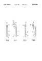
- FIG. 1is a side view of an embodiment of an apparatus constructed in accordance with the invention
- FIG. 2is a side view of another embodiment of an apparatus constructed in accordance with the invention, which omits the second retaining device with washer and nut;
- FIG. 3is a side view of another embodiment of an apparatus constructed in accordance with the invention.
- FIG. 4is a side view of still another embodiment of an apparatus constructed in accordance with the invention.
- FIG. 5shows a retaining device in accordance with the invention.
- FIGS. 6 to 9are front and back views of several embodiments of screw-shaped retaining devices constructed in accordance with the invention.
- FIG. 1shows a first embodiment of an apparatus 10 for the stiffening and/or correction of a part of the vertebral column consisting of at least two vertebrae (not illustrated).
- the embodiment of the apparatus 10 according to FIG. 1is suitable for dorsal implantation in the lumbar, thoracic and lower cervical regions of the vertebral column and for ventral implantation in the lumbar and middle to lower thoracic regions.
- the fusioncan either occur in situ, with or without additional intervention such as decompression, debridement etc., or be accompanied by correction of positional defects such as scoliosis, kyphosis, rotation etc., in which case the etiology of the deformity--trauma, osseous defects, neurogenic, musculogenic or congenital deformities and so on--is irrelevant.
- the first embodiment of the apparatus 10, in FIG. 1,comprises two screw-shaped retaining devices 12, each of which can be fixed to one of the vertebrae of the affected part of the vertebral column.
- a retaining device 12is screwed into the pedicle, i.e. into the vertebral arch between spinous process, transverse process and the corresponding superior articular process.
- the screw-shaped retaining devices 12each comprise a screw shaft 14 with a screw thread 16 by which to be screwed into the vertebra of the affected part of the vertebral column.
- the screw-shaped retaining devices 12each further comprise a screw head 18 to receive and fix a rod-shaped connecting element 20.
- the screw head 18 of the screw-shaped retaining device 12--as shown in FIGS. 6 and 7--is provided with a bore, preferably a central bore 22.
- the screw-shaped retaining device 12can thus be slipped or otherwise placed onto the rod-shaped connecting element 20 by a sliding movement in the direction of the long axis of the connecting element 20 or of the central bore 22 provided in the screw head 18.
- the embodiment of the screw-shaped retaining device 12 according to FIG. 7differs from that according to FIG. 6 merely in that the screw head 20 with the central bore 22 is additionally connected to the screw shaft 14 of the screw-shaped retaining device 12 by way of a cross bridge 24 and a longitudinal bridge 26.
- This arrangementachieves an additional degree of freedom in the manipulation of the apparatus 10 in accordance with the invention, with the result that the connecting element 20 can be precisely adjusted and if necessary, positional correction can be carried out after the initial placement.
- the additional degree of freedomrefers to the different orientation of the rod relative to the screw as provided by the two devices.
- the screw in FIG. 6provides direct rotation of the screw shaft on the rod axis.
- the screw of FIG. 7provides rotational positioning of the rod in the screw head on a circle about the rod axis.
- the two unitstogether provide additional freedom of movement for positioning in use.
- the screw head 18 of the screw-shaped retaining device 12is alternatively--as shown in FIGS. 8 and 9--provided with a longitudinal slot, preferably a median longitudinal slot 28, or similar slot-shaped recess.
- the screw-shaped retaining device 12can thus be brought onto the rod-shaped connecting element 20 by a sideways placement movement or the like, as a result of which the screw-shaped retaining device 12 becomes considerably easier for the surgeon to manipulate during the operation.
- the embodiment of the screw-shaped retaining device 12 according to FIG. 9differs from that according to FIG. 8 only in that the screw head 18 is not directly continuous with the screw shaft 14 of the screw-shaped retaining device 12, but rather is connected to the screw shaft 14 by way of a cross bridge 30. It is also conceivable in this regard for the screw head 18 and the screw shaft 14 to be connected to one another by way of a longitudinal bridge (not illustrated) extending in the long direction of the screw-shaped retaining device 12, instead of the cross bridge 30.
- the resulting additional degree of freedomincreases many-fold the precision during adjustment and, where necessary, later positional correction by the apparatus 10 in accordance with the invention for the stiffening and/or correction of the part of the vertebral column.
- the apparatus 10 in accordance with the inventioncan be flexibly adapted to the particular anatomical features of each individual patient, so that the entire apparatus 10 is extremely versatile in application.
- the two retaining devices 12are provided to receive and fix a compression or distraction rod 32 that connects the two retaining devices 12 to one another.
- the compression or distraction rod 32comprises on the one hand the rod-shaped connecting element 20 receivable by the retaining devices 12, and on the other hand at least one, in the illustration only one, distance element 34.
- the distance element 34can be received displaceably and substantially without play by the rod-shaped connecting element 20 corresponding to the retaining devices 12. Furthermore, the distance element 34 is disposed between two adjacent retaining devices 12, in order to maintain the distance between these two retaining devices 12.
- the connecting element 20is provided at one end 36 with a screw thread 38, which cooperates with a nut 40 as shown in FIG. 1.
- the connecting element 20 according to FIG. 1is likewise equipped with a screw thread 44 for a nut 46.
- a plain washer 48, a locking ring or the likeAt each of the two ends, between the nut 40 or 46 and the neighboring retaining device 12 there is disposed on the connecting element 20 a plain washer 48, a locking ring or the like. Consequently when the two nuts 40, 46 are tightened, the two retaining devices 12 and the distance element 34 disposed between the two retaining devices 12 are fixed to one another or even braced against one another.
- FIG. 2The further embodiment of the apparatus 10 in accordance with the invention for the stiffening and/or correction of part of the vertebral column according to FIG. 2 is distinguished from that in FIG. 1 merely in that the connecting element 20 is provided at the one end 36 with a screw thread 38 and a nut 40 (not shown), but at the other end 42 with a flange-like thickening 50 or the like instead of the screw thread 44 and the nut 46.
- the two retaining devices 12 and the distance element 34 inserted between the two retaining devices 12, all of which are disposed on the connecting element 20are fixed to one another or mutually braced between the flange-like thickening and the one (not illustrated) nut 40 merely by tightening said nut.
- a plain washer, locking ring or the like not illustrated in FIG. 2can be provided. All the remaining components that correspond to those of the embodiment of the apparatus 10 according to FIG. 1 are indicated by the same reference numerals.
- the faces 52 of the two ends 54, 56 of the at least one, here the only, distance element 34lie in the plane perpendicular to the long axis of the distance element 34, in the drawing also perpendicular to the plane of the page.
- the distance element 34 according to FIGS. 1 and 2thus has the form of a hollow cylinder cut straight across at both ends.
- the embodiment of the apparatus 10 in accordance with the invention for the stiffening and/or correction of part of the vertebral column shown in FIG. 3differs from that of FIG. 1 only in the special form of the individual distance elements 34', 34" and 34'". All the remaining components that correspond to those of the embodiment of the apparatus 10 according to FIG. 1 are indicated by the same reference numerals.
- one of the faces 52' of the two ends 54', 56', here the end 54'lies in the plane perpendicular to the long axis of the distance element 34' and to the plane of the page. Furthermore, in the case of the two distance elements 34' in FIG. 3 one of the faces 52' of the two ends 54', 56', here the end 56', lies in a plane other than that perpendicular to the long axis of the distance element 34' and hence also to the plane of the page.
- the distance element 34'is thus quasi a hollow cylinder with one end cut straight across and the other slanted.
- Another distance element 34"according to FIG. 3 has faces 52" at both ends 54", 56" that lie in a plane different from that perpendicular to the long axis of the distance element 34" and hence also to the plane of the page.
- the distance element 34"thus has the form of a hollow cylinder or the like with both ends cut at an angle.
- FIG. 3also shows a distance element 34'", the outer circumference of which is provided with a key surface or the like, to allow the distance element 34'" to be rotated about its long axis by means of a tool, in particular a wrench.
- One of the faces 52'" of the two ends 54'", 56'" of the distance element 34'"lies in the plane perpendicular to the long axis of the distance element 34'" and one of the faces 52'" of the two ends 54'", 56'" of the distance element 34 lies in a plane other than that perpendicular to the long axis of the distance element 34'".
- the connecting element 20 of the compression or distraction rod 32is angled or bent in one direction as a result of the particular arrangement of the distance elements 34', 34" and 34'" with respect to one another and their special form at the ends 54', 56', 54", 56" and 54'", 56'". Furthermore, by rotating the individual distance elements 34', 34" and 34'" with respect to one another the compressive or distractive action and the bracing force can be precisely adjusted.
- the embodiment of the apparatus 10 in accordance with the invention for the stiffening and/or correction of part of the vertebral column shown in FIG. 4likewise differs from that according to FIG. 1 basically with respect to the special arrangement and form of the distance elements 34, 34' and 34'". All the components that correspond to those of the embodiment of the apparatus 10 according to FIG. 1 are again indicated by the same reference numerals.
- an additional rod-shaped connecting element 60that can be received by retaining devices 12.
- the connecting element 60can, as illustrated in FIG. 4, be arranged at least partly and substantially in parallel with the connecting element 20 and be fixed relative to the latter.
- the distance element 34"" and the distance element 34are joined to one another, for example, by a welded joint 62.
- two rod-shaped connecting elements 20, 68 receivable by the retaining devices 12can, as indicated schematically in FIG. 5, be connected to one another by way of holding elements 64.
- the holding elements 64are provided with two or more slotlike or similar recesses 66, which serve to receive the two rod-shaped connecting elements 20, 60 substantially without play.
- the distance elements 34, 34', 34", 34'" and 34""can all be made of various lengths, making it possible to employ the apparatus 10 flexibly.
- FIG. 2ais an illustration of the structure as shown in FIGS. 1 and 2, with an element 34 and a second element 34a of a different length than element 34.
- FIG. 2aclearly illustrates the adjacent distance elements 34 and 34a to control the spacings between the detaining devices 12.
- FIG. 4aillustrates a particular roughened surface on one end of a distance element 34.
- the faces 52, 52', 52", 52'", 52"" of each distance element 34, 34', 34", 34'" and 34""are provided with grooves, notches or the like and projections etc., illustrated in FIG. 4a of the drawings, which are disposed approximately radially with respect to the long axis of the distance elements 34, 34', 34", 34'" and 34"".
- the retaining devices 12 and/or the rod-shaped connecting element 20, 60, 68 and/or the nuts 40, 46 that cooperate with the rod-shaped connecting element 20, 60, 68are preferably made of metal, in particular titanium or an alloy thereof.
- hook-shaped retaining devices(not illustrated) could be employed, which can be attached to the individual vertebrae of the affected part of the vertebral column in a conventional manner.
Landscapes
- Health & Medical Sciences (AREA)
- Orthopedic Medicine & Surgery (AREA)
- Surgery (AREA)
- Life Sciences & Earth Sciences (AREA)
- Neurology (AREA)
- Animal Behavior & Ethology (AREA)
- Veterinary Medicine (AREA)
- Public Health (AREA)
- Heart & Thoracic Surgery (AREA)
- General Health & Medical Sciences (AREA)
- Engineering & Computer Science (AREA)
- Molecular Biology (AREA)
- Medical Informatics (AREA)
- Biomedical Technology (AREA)
- Nuclear Medicine, Radiotherapy & Molecular Imaging (AREA)
- Vascular Medicine (AREA)
- Chemical & Material Sciences (AREA)
- Epidemiology (AREA)
- Inorganic Chemistry (AREA)
- Chemical Kinetics & Catalysis (AREA)
- Surgical Instruments (AREA)
- Prostheses (AREA)
- Orthopedics, Nursing, And Contraception (AREA)
- Pharmaceuticals Containing Other Organic And Inorganic Compounds (AREA)
- Superconductors And Manufacturing Methods Therefor (AREA)
Abstract
Description
The invention relates to an apparatus for stiffening and/or correcting a part of the vertebral column consisting of at least two vertebrae, according to the precharacterizing clause in claim 1.
Apparatuses of this kind for stiffening and/or correcting a part of the vertebral column consisting of at least two vertebrae are known in the state of the art. Such an apparatus comprises at least two screw-like retaining devices, which can be appropriately fixed to one of the vertebrae in the affected part of the vertebral column. The retaining devices are provided to receive and hold in place a compression or distraction rod that connects the retaining devices to one another. This arrangement allows stiffening or so-called spondylodesis of individual parts of the vertebral column and/or correction in cases of spinal curvature (scoliosis, kyphosis), misalignment (rotation), injury (trauma), neoplasms (tumor) and in particular abrasion or degenerative spinal disease, according to the principle of osteosynthesis that is as rigid as possible and hence extremely stable mechanically.
The retaining devices in these apparatuses as a rule take the form of screws or so-called pedicle screws as well as hooks known per se, which can be connected to one another by way of a mechanically stable compression or distraction rod. An aspect of these apparatuses that has proved decidedly disadvantageous is the structure of the part that connects each retaining device to the compression or distraction rod. On the one hand, the height of the connecting part of these apparatuses is usually relatively great, which severely delays healing after surgery. On the other hand, various mechanical problems are encountered in assembling the apparatus, which both prevent permanent fixation and make it impossible to carry out corrective repositioning later on. Another disadvantage of these apparatuses is that they offer little or no opportunity to vary the length of the fixed region. Instead, different apparatuses must be used, some exclusively for short lengths and others exclusively for great lengths, and because they are not interchangeable their versatility in use is severely restricted. Furthermore, only a very limited force can be applied to these apparatuses, not least because of their construction, in order to correct misalignments of the affected part of the spine. Finally, all these apparatuses are also relatively expensive.
The invention is thus directed to the disclosing an apparatus of this generic kind for the stiffening and/or correction of a part of the vertebral column consisting of at least two vertebrae, which eliminates all the disadvantages of apparatuses known in the state of the art: in particular, the apparatus of this invention is very small in construction, enables permanent, non-self-releasing fixation and can be repositioned after the initial placement, is versatile in use and is able to sustain large forces.
This problem is solved by the characterizing features in claim 1.
By the construction in accordance with the invention, such that the compression or distraction rod comprises a rod-shaped connecting element that can be received by the retaining devices and at least one distance element, each of which is displaceably receivable by the rod-shaped connecting element and positioned between two adjacent retaining devices so as to determine the distance between these retaining devices, the connecting element being provided at one end with a screw thread and at the other end likewise with a screw thread or where appropriate with a flange-like thickening or the like to fix or brace the retaining devices and distance element, various advantages are achieved simultaneously. Not only is the structure compact, it also enables permanent fixation of the apparatus in accordance with the invention after the surgical operation, so that the retaining devices do not release themselves from the connecting element with the at least one distance element that comprise the compression or distraction rod as a whole. Furthermore, the apparatus in accordance with the invention is extremely easy to manipulate during the operation, and at the same time, after its initial placement it can be repositioned by the surgeon with no difficulty. In addition, the apparatus in accordance with the invention can be used in many different situations, because its length is arbitrarily adjustable by way of a rod-shaped connecting element of varying length and one or more distance elements of different lengths, so that it can be adapted to the particular spatial and body-specific peculiarities of each individual patient. Finally, with the apparatus in accordance with the invention a very large force can be exerted because of an immediate postoperative stability at and between the vertebrae of the affected part of the vertebral column, so that positional adjustment or correction of a misalignment can be achieved by the apparatus of the invention itself. As an alternative to the construction with screw-like retaining devices, it is equally possible to employ hook-shaped retaining devices such as are known in the state of the art.
Other forms of the invention are disclosed described in claims 2 to 19.
According to one feature within the scope of the invention the faces of the two ends of the at least one distance element coincide with the plane perpendicular to the long axis of the distance element. In this embodiment, therefore, the distance element consists of a hollow cylinder or the like with both ends straight, so that the retaining devices that abut the distance element extend exactly perpendicular to the distance element itself and to the rod-shaped connecting element of the compression or distraction rod.
In an alternative design, one of the faces of the two ends of the at least one distance element lies in the plane perpendicular to the long axis of the distance element and one of the faces of the two ends of the at least one distance element lies in a plane other than the plane perpendicular to the long axis of the distance element. In this embodiment of the distance element, therefore, the hollow cylinder or the like is cut straight at one end and slanted at one end, so that one of the retaining devices that abut the distance element extends exactly perpendicular to and the other is slanted at an angle to the distance element itself and to the rod-shaped connecting element of the compression or distraction rod. As a result, for example, slight inaccuracies in inserting one of the two retaining devices into the vertebra, due to an imprecisely centered bore or the like, can later be corrected and compensated. Correspondingly, it is possible to adjust the vertebrae in the part of the vertebral column to be stiffened or corrected exactly with respect to one another during the operation by arranging several distance elements with differently shaped ends on the rod-shaped connecting element of the compression or distraction rod, in any desired combination.
Accordingly, it is also provided in accordance with the invention that the faces of both ends of the at least one distance element lie in a plane other than the plane perpendicular to the long axis of the distance element. In this embodiment, therefore, the distance element is a hollow cylinder or the like cut at an angle at both ends, so that each of the retaining devices abutting the distance element is slanted at a corresponding angle to the distance element itself and to the rod-shaped connecting element of the compression or distraction rod. Thus the apparatus in accordance with the invention can be adapted to all kinds of anatomical peculiarities of the patient.
The distance element is advantageously constructed in different lengths, which can additionally increase the versatility of the apparatus in accordance with the invention in dependence on the length of the rod-shaped connecting element.
Of special interest for high rotational stability of the at least one distance element with respect to the two adjacent retaining devices, or of the distance elements with respect to one another, are other special characteristics of the elements. According to these, the end faces of each distance element are roughened to provide rotationally stable contact with the retaining device or devices and/or with the adjacent distance element or elements. In particular, to achieve rotationally stable contact the end faces of each distance element are provided with approximately radially oriented grooves, notches or the like and with corresponding projections. It is also entirely conceivable in this regard that the retaining devices, in those regions that can be brought into contact with the faces of the distance element or elements, are similarly roughened or provided with such radially oriented grooves, notches, etc. as well as projections, etc.
In order to further improve the manipulability of the apparatus in accordance with the invention, the at least one distance element has at its outer circumference a key surface, by means of which the distance element can be rotated about its long axis during installation by means of a tool, in particular a wrench. This also offers the advantage that the apparatus can be adjusted or its position precisely corrected, as necessitated by the deformation or misalignment of the vertebrae in the affected part of the vertebral column. Quite apart from this, given that at least the one distance element has at least one end cut at an angle with respect to its long axis, the bracing force to be exerted, i.e. the clamping force, can in addition be easily, rapidly and precisely adjusted during the surgical operation.
Further features of crucial significance for the versatility of the apparatus in accordance with the invention are also disclosed. That is, there can be provided an additional rod-shaped connecting element, also receivable by retaining devices, that can be arranged at least partially and substantially parallel to the one rod-shaped connecting element receivable by retaining devices and fixed in position with respect to the latter. As a result of such an additional means of fixing the compression or distraction rod, the stability of the apparatus in accordance with the invention can be further increased, so that the affected part of the vertebral column is more stably anchored.
One way to implement such features include having at least one distance element and substantially in parallel therewith having an additional distance element inseparably attached to the first element, in particular by welding. The additional, substantially parallel distance element serves simultaneously to join or connect two apparatuses to be installed in accordance with the invention, whereby it allows arbitrary lengthening or extension of the one or the other previously installed apparatus, and to displace the entire compression or distraction rod in order to adjust the latter to the particular anatomical peculiarities of the patient.
As an alternative to the above embodiment of the apparatus the two rod-shaped connecting elements, receivable by the retaining devices, are connected with one another by way of holder elements that preferably include two or more apertures or the like within which the two rod-shaped connecting elements can be seated with no play.
The retaining devices may also advantageously each comprise a threaded screw shaft to be screwed into the vertebra and a screw head to receive and fix the rod-shaped connecting element. In addition to enabling permanent fixation of the apparatus in accordance with the invention for the purpose of stiffening and/or correcting a part of the vertebral column comprising at least two vertebrae, this embodiment is especially small in size while simultaneously allowing the transfer of large forces, so as to ensure that great force can be applied.
As an additional advantageous means of preventing the whole apparatus from coming loose of its own accord, it is provided in accordance with the invention that the screw head of the screw-shaped retaining device includes a bore, preferably a central bore, into or through which the rod-shaped connecting element can be inserted, substantially without play, by displacing the latter in the direction of its long axis.
In a design alternative to the immediately above, the screw head of the screw-shaped retaining device is provided with a longitudinal slot, into which the rod-shaped connecting element can be set approximately without play by a sideways displacement. This measure enormously simplifies the manipulation of the apparatus in accordance with the invention as it is installed or removed during the surgical operation.
To improve the correction possibilities still further, it is also within the scope of the invention that the screw head and the screw shaft of the screw-shaped retaining device are connected to one another by a transverse bridge and/or by a longitudinal bridge.
In a preferred embodiment of the invention the retaining device and/or the rod-shaped connecting element and/or the nuts that cooperate with the connecting element are made of metal, in particular a metal alloy. A suitable metal or metal alloy, for example, is titanium or an alloy thereof. Such a material increases the compatibility of the apparatus in accordance with the invention even during surgery as well as in the subsequent healing phase, and hence enhances the quality of the operation. In this regard, of course, the material of which the rod-shaped connecting element is made should be such that the rod-shaped connecting element is both highly resistant to bending and nevertheless capable of being bent to at least a certain degree, to permit fine adjustment and/or precise positional correction of the apparatus in accordance with the invention during the operation.
To increase the compatibility of the apparatus, the distance element(s) also consist of metal, in particular titanium or an alloy thereof.
Finally, the distance element(s) can alternatively or cumulatively also be made of a somewhat elastic/flexible material such as polyethylene. The apparatus in accordance with the invention can then stiffen a part of the vertebral column up to a predetermined degree, which depends on the flexibility and elasticity of the material and of the arrangement as a whole.
Additional characteristics, advantages and details of the invention will become apparent in the following description of some preferred embodiments of the invention, with reference to the drawings, wherein:
FIG. 1 is a side view of an embodiment of an apparatus constructed in accordance with the invention;
FIG. 2 is a side view of another embodiment of an apparatus constructed in accordance with the invention, which omits the second retaining device with washer and nut;
FIG. 3 is a side view of another embodiment of an apparatus constructed in accordance with the invention;
FIG. 4 is a side view of still another embodiment of an apparatus constructed in accordance with the invention;
FIG. 5 shows a retaining device in accordance with the invention; and
FIGS. 6 to 9 are front and back views of several embodiments of screw-shaped retaining devices constructed in accordance with the invention.
FIG. 1 shows a first embodiment of anapparatus 10 for the stiffening and/or correction of a part of the vertebral column consisting of at least two vertebrae (not illustrated). The embodiment of theapparatus 10 according to FIG. 1, like the other embodiments of theapparatus 10 according to FIGS. 2 to 4, is suitable for dorsal implantation in the lumbar, thoracic and lower cervical regions of the vertebral column and for ventral implantation in the lumbar and middle to lower thoracic regions. For both dorsal and ventral application of theapparatus 10 the fusion can either occur in situ, with or without additional intervention such as decompression, debridement etc., or be accompanied by correction of positional defects such as scoliosis, kyphosis, rotation etc., in which case the etiology of the deformity--trauma, osseous defects, neurogenic, musculogenic or congenital deformities and so on--is irrelevant.
The first embodiment of theapparatus 10, in FIG. 1, comprises two screw-shapedretaining devices 12, each of which can be fixed to one of the vertebrae of the affected part of the vertebral column. In particular, such aretaining device 12 is screwed into the pedicle, i.e. into the vertebral arch between spinous process, transverse process and the corresponding superior articular process.
The screw-shapedretaining devices 12 each comprise ascrew shaft 14 with ascrew thread 16 by which to be screwed into the vertebra of the affected part of the vertebral column. The screw-shapedretaining devices 12 each further comprise ascrew head 18 to receive and fix a rod-shaped connectingelement 20.
In order to receive the rod-shaped connectingelement 20 approximately without play, thescrew head 18 of the screw-shapedretaining device 12--as shown in FIGS. 6 and 7--is provided with a bore, preferably acentral bore 22. The screw-shapedretaining device 12 can thus be slipped or otherwise placed onto the rod-shaped connectingelement 20 by a sliding movement in the direction of the long axis of the connectingelement 20 or of thecentral bore 22 provided in thescrew head 18.
The embodiment of the screw-shapedretaining device 12 according to FIG. 7 differs from that according to FIG. 6 merely in that thescrew head 20 with thecentral bore 22 is additionally connected to thescrew shaft 14 of the screw-shapedretaining device 12 by way of across bridge 24 and alongitudinal bridge 26. This arrangement achieves an additional degree of freedom in the manipulation of theapparatus 10 in accordance with the invention, with the result that the connectingelement 20 can be precisely adjusted and if necessary, positional correction can be carried out after the initial placement. The additional degree of freedom refers to the different orientation of the rod relative to the screw as provided by the two devices. Thus, the screw in FIG. 6 provides direct rotation of the screw shaft on the rod axis. The screw of FIG. 7 provides rotational positioning of the rod in the screw head on a circle about the rod axis. Thus the two units together provide additional freedom of movement for positioning in use.
So that the rod-shaped connectingelement 20 can be received substantially without play, thescrew head 18 of the screw-shapedretaining device 12 is alternatively--as shown in FIGS. 8 and 9--provided with a longitudinal slot, preferably a medianlongitudinal slot 28, or similar slot-shaped recess. The screw-shapedretaining device 12 can thus be brought onto the rod-shaped connectingelement 20 by a sideways placement movement or the like, as a result of which the screw-shapedretaining device 12 becomes considerably easier for the surgeon to manipulate during the operation.
The embodiment of the screw-shapedretaining device 12 according to FIG. 9 differs from that according to FIG. 8 only in that thescrew head 18 is not directly continuous with thescrew shaft 14 of the screw-shapedretaining device 12, but rather is connected to thescrew shaft 14 by way of across bridge 30. It is also conceivable in this regard for thescrew head 18 and thescrew shaft 14 to be connected to one another by way of a longitudinal bridge (not illustrated) extending in the long direction of the screw-shapedretaining device 12, instead of thecross bridge 30. The resulting additional degree of freedom increases many-fold the precision during adjustment and, where necessary, later positional correction by theapparatus 10 in accordance with the invention for the stiffening and/or correction of the part of the vertebral column. Furthermore, theapparatus 10 in accordance with the invention can be flexibly adapted to the particular anatomical features of each individual patient, so that theentire apparatus 10 is extremely versatile in application.
The tworetaining devices 12 according to FIG. 1 are provided to receive and fix a compression ordistraction rod 32 that connects the tworetaining devices 12 to one another. The compression ordistraction rod 32 comprises on the one hand the rod-shaped connectingelement 20 receivable by the retainingdevices 12, and on the other hand at least one, in the illustration only one,distance element 34. Thedistance element 34 can be received displaceably and substantially without play by the rod-shaped connectingelement 20 corresponding to the retainingdevices 12. Furthermore, thedistance element 34 is disposed between twoadjacent retaining devices 12, in order to maintain the distance between these two retainingdevices 12.
As is clearly evident in FIGS. 1 and 2, the connectingelement 20 is provided at oneend 36 with ascrew thread 38, which cooperates with anut 40 as shown in FIG. 1. At theother end 42 the connectingelement 20 according to FIG. 1 is likewise equipped with a screw thread 44 for anut 46. At each of the two ends, between thenut device 12 there is disposed on the connecting element 20 aplain washer 48, a locking ring or the like. Consequently when the twonuts retaining devices 12 and thedistance element 34 disposed between the tworetaining devices 12 are fixed to one another or even braced against one another.
The further embodiment of theapparatus 10 in accordance with the invention for the stiffening and/or correction of part of the vertebral column according to FIG. 2 is distinguished from that in FIG. 1 merely in that the connectingelement 20 is provided at the oneend 36 with ascrew thread 38 and a nut 40 (not shown), but at theother end 42 with a flange-like thickening 50 or the like instead of the screw thread 44 and thenut 46. Here, therefore, the tworetaining devices 12 and thedistance element 34 inserted between the tworetaining devices 12, all of which are disposed on the connectingelement 20, are fixed to one another or mutually braced between the flange-like thickening and the one (not illustrated)nut 40 merely by tightening said nut. As an additional means of reliably preventing the apparatus from loosening of its own accord, for example, a plain washer, locking ring or the like not illustrated in FIG. 2 can be provided. All the remaining components that correspond to those of the embodiment of theapparatus 10 according to FIG. 1 are indicated by the same reference numerals.
As is further evident in FIGS. 1 and 2, thefaces 52 of the two ends 54, 56 of the at least one, here the only,distance element 34 lie in the plane perpendicular to the long axis of thedistance element 34, in the drawing also perpendicular to the plane of the page. Thedistance element 34 according to FIGS. 1 and 2 thus has the form of a hollow cylinder cut straight across at both ends.
The embodiment of theapparatus 10 in accordance with the invention for the stiffening and/or correction of part of the vertebral column shown in FIG. 3 differs from that of FIG. 1 only in the special form of theindividual distance elements 34', 34" and 34'". All the remaining components that correspond to those of the embodiment of theapparatus 10 according to FIG. 1 are indicated by the same reference numerals.
As shown in FIG. 3, in the case of the two distance elements 34' one of the faces 52' of the two ends 54', 56', here the end 54', lies in the plane perpendicular to the long axis of the distance element 34' and to the plane of the page. Furthermore, in the case of the two distance elements 34' in FIG. 3 one of the faces 52' of the two ends 54', 56', here the end 56', lies in a plane other than that perpendicular to the long axis of the distance element 34' and hence also to the plane of the page. The distance element 34' is thus quasi a hollow cylinder with one end cut straight across and the other slanted.
Anotherdistance element 34" according to FIG. 3 has faces 52" at both ends 54", 56" that lie in a plane different from that perpendicular to the long axis of thedistance element 34" and hence also to the plane of the page. Thedistance element 34" thus has the form of a hollow cylinder or the like with both ends cut at an angle.
Finally, FIG. 3 also shows a distance element 34'", the outer circumference of which is provided with a key surface or the like, to allow the distance element 34'" to be rotated about its long axis by means of a tool, in particular a wrench. One of the faces 52'" of the two ends 54'", 56'" of the distance element 34'" lies in the plane perpendicular to the long axis of the distance element 34'" and one of the faces 52'" of the two ends 54'", 56'" of thedistance element 34 lies in a plane other than that perpendicular to the long axis of the distance element 34'".
According to FIG. 3 the connectingelement 20 of the compression ordistraction rod 32 is angled or bent in one direction as a result of the particular arrangement of thedistance elements 34', 34" and 34'" with respect to one another and their special form at theends 54', 56', 54", 56" and 54'", 56'". Furthermore, by rotating theindividual distance elements 34', 34" and 34'" with respect to one another the compressive or distractive action and the bracing force can be precisely adjusted.
The embodiment of theapparatus 10 in accordance with the invention for the stiffening and/or correction of part of the vertebral column shown in FIG. 4 likewise differs from that according to FIG. 1 basically with respect to the special arrangement and form of thedistance elements 34, 34' and 34'". All the components that correspond to those of the embodiment of theapparatus 10 according to FIG. 1 are again indicated by the same reference numerals.
In theapparatus 10 according to FIG. 4 there is provided, in addition to the connectingelement 20 that connects two screw-shapedretaining devices 12 to one another, an additional rod-shaped connectingelement 60 that can be received by retainingdevices 12. The connectingelement 60 can, as illustrated in FIG. 4, be arranged at least partly and substantially in parallel with the connectingelement 20 and be fixed relative to the latter. For this purpose there is non-detachably disposed at the at least onedistance element 34"", substantially in parallel therewith, anadditional distance element 34. According to FIG. 4 thedistance element 34"" and thedistance element 34 are joined to one another, for example, by a welded joint 62.
In alternative and/or cumulative elaboration of the invention, two rod-shaped connectingelements devices 12 can, as indicated schematically in FIG. 5, be connected to one another by way of holdingelements 64. The holdingelements 64 are provided with two or more slotlike orsimilar recesses 66, which serve to receive the two rod-shaped connectingelements distance elements apparatus 10 flexibly. Thus, as shown in FIG. 2a, is an illustration of the structure as shown in FIGS. 1 and 2, with anelement 34 and asecond element 34a of a different length thanelement 34. FIG. 2a clearly illustrates theadjacent distance elements devices 12.
In addition, thefaces distance element distance element 34. In particular, thefaces distance element distance elements
The retainingdevices 12 and/or the rod-shaped connectingelement element
The present invention is not restricted to the exemplary embodiments described above. In particular, it is conceivable that instead of screw-shapedretaining devices 12, hook-shaped retaining devices (not illustrated) could be employed, which can be attached to the individual vertebrae of the affected part of the vertebral column in a conventional manner.
All the characteristics disclosed in the application documents are claimed as essential to the invention, to the extent that they are new to the state of the art singly or in combination.
Claims (20)
1. An apparatus for attachment to a vertebrae column having at least two vertebral comprising first and second screw-shaped retaining devices (12), each said device being adapted to be fixed to one vertebrae of the vertebral column and are attached to a rod (32) which connects the retaining devices (12) to one another, the improvement wherein said
rod (32) includes an elongated rod-shaped connecting element (20) having a first end and a second end, said first and second screw-shaped retaining devices (12) being mounted on said connecting element and movable along the connecting element, at least one distance element (34, 34', 34", 34'", 34"") movably mounted on the rod-shaped connecting element (2) between said first and second retaining devices (12) and establishing and maintaining a selected distance between said first and second retaining devices (12), said connecting element having a screw thread (38) on said first end of said connecting element and having an abutment element (44) on said second end of said connecting element and a fixing member threaded onto said screw thread with the retaining devices and said at least one distance element between the fixing member and the abutment element, the fixing member for moving said first retaining device, so that said at least one distance element extends from the first retaining device to the second retaining device to be in abutment with both the first and the second retaining device, while said fixing member abuts the first retaining device and said abutment member abuts the second retaining device to fix said retaining devices (12) and said at least one distance element (34, 34', 34", 34'", 34"") on said connecting element.
2. The apparatus according to claim 1, wherein said at least one distance element (34) has a long axis and having a first and a second end (54, 56), said first and second ends each having a planar end face (52) which lies in a plane perpendicular to the long axis of the distance element (34).
3. The apparatus according to claim 1, wherein said at least one distance element has a long axis and opposite end faces and at least one of the opposite end faces (52') lies in a plane offset by an angle from a plane perpendicular to the long axis of the distance element (34').
4. The apparatus of claim 1, wherein said at last one distance element includes a plurality of distance elements (34, 34', 34", 34'", 34""), each one of said plurality of distance elements having a fixed length and having a different length from the other of said distance elements of said plurality of distance elements.
5. The apparatus of claim 4, wherein each of said distance elements (34, 34', ÷", 34'", 34"") has a first and second end face, each of said first and second end faces is roughened to provide rotationally stabilized contact with said retaining device (12) and said adjacent distance element (34, 34', 34", 34'", 34"").
6. The apparatus of claim 4, wherein each of said distance elements includes substantially located radially oriented grooves and projections to provide rotationally stabilized contact with the retaining devices (12) and between adjacent distance elements (34, 34', 34", 34'", 34"").
7. The apparatus according to claim 1, wherein said at least one distance element (34'") has an outer surface, a key surface on said outer surface, said key surface adapting said at least one distance element (34'") for receiving a matching tool for rotating of said at least one distance element on said connecting element.
8. The apparatus of claim 1, wherein said rod shaped connector element is a first rod shaped connector element, said apparatus further including a second rod-shaped connecting element (60, 68) located at least partly and substantially in parallel with said first rod-shaped connecting element (20), at least one second distance element on said second connecting element, and a mount unit mounting said second rod-shaped connecting element in position relative to the first connecting element (20).
9. The apparatus of claim 8, wherein one of said at least one second distance elements is nondetachably attached to said second connecting element (60) in substantially parallel relation to said at least one distance element (34) on said first connecting element (20).
10. The apparatus of claim 8, including holding elements (64) connected to said first and said second rod-shaped connecting elements (20, 68) and supporting said connecting elements to one another.
11. The apparatus of claim 10, wherein each of said holding elements (64) includes at least two recesses (66) to receive the first and second rod-shaped connecting elements (20, 68) and said recesses being substantially the same shape as said connecting elements to support the connecting elements with minimal play.
12. The apparatus according to claim 1, wherein each of said screw-shaped retaining devices (12) comprises a screw shaft (14) with a screw thread (16) to be screwed into a vertebrae and a screw head (18) fixed in position on the rod-shaped connecting element (20).
13. The apparatus according to claim 12, wherein said screw head includes a bore (22) for mounting on said rod-shaped connecting element (20) said bore having a shape substantially the same as said connecting element to minimize play therebetween.
14. The apparatus according to claim 12, wherein said screw head (18) includes a longitudinal slot to receive the rod-shaped connecting element (20), said slot having a shape substantially the same as said connecting element to minimize play therebetween.
15. The apparatus according to claim 12, wherein the screw head (18) is offset from said screw shaft (14) of the screw-shaped retaining device (12), said head having an outwardly extending longitudinal bridge extending parallel to the screw shaft and a cross bridge connected to the longitudinal bridge and to said screw shaft, said cross bridge extending laterally from said longitudinal bridge to said screw shaft.
16. The apparatus of claim 1, wherein said fixing member is a nut and said abutment element is a nut, and at least one of said retaining devices (12), said rod-shaped connecting element (20, 60, 68) and said nuts (40, 46) are made of a metal alloy.
17. The apparatus of claim 1, wherein said at least one distance element (34, 34', 34", 34'", 34"") is made of titanium.
18. The apparatus of claim 1 wherein said at least one distance element (34, 34', 34", 34'", 34"") is made of an elastic material.
19. The apparatus of claim 18 wherein said elastic material is polyethylene.
20. The apparatus of claim 1 wherein said at least one distance element is made of titanium alloy.
Applications Claiming Priority (3)
| Application Number | Priority Date | Filing Date | Title |
|---|---|---|---|
| DE4303770ADE4303770C1 (en) | 1993-02-09 | 1993-02-09 | Stiffening and correction system for spinal vertebrae - comprises screw-ended holders with connecting rod supporting clamped distance pieces. |
| DE4303770.4 | 1993-02-09 | ||
| PCT/EP1994/000302WO1994017745A1 (en) | 1993-02-09 | 1994-02-02 | Device for stiffening and/or correcting the spine |
Publications (1)
| Publication Number | Publication Date |
|---|---|
| US5562660Atrue US5562660A (en) | 1996-10-08 |
Family
ID=6480001
Family Applications (1)
| Application Number | Title | Priority Date | Filing Date |
|---|---|---|---|
| US08/318,894Expired - Fee RelatedUS5562660A (en) | 1993-02-09 | 1994-02-02 | Apparatus for stiffening and/or correcting the vertebral column |
Country Status (6)
| Country | Link |
|---|---|
| US (1) | US5562660A (en) |
| EP (1) | EP0634912B1 (en) |
| JP (1) | JPH07506040A (en) |
| AT (1) | ATE160277T1 (en) |
| DE (2) | DE4303770C1 (en) |
| WO (1) | WO1994017745A1 (en) |
Cited By (187)
| Publication number | Priority date | Publication date | Assignee | Title |
|---|---|---|---|---|
| US5938662A (en)* | 1998-02-24 | 1999-08-17 | Beere Precision Medical Instruments, Inc. | Human spine fixation template and method of making same |
| US6102912A (en)* | 1997-05-29 | 2000-08-15 | Sofamor S.N.C. | Vertebral rod of constant section for spinal osteosynthesis instrumentations |
| US20020035366A1 (en)* | 2000-09-18 | 2002-03-21 | Reto Walder | Pedicle screw for intervertebral support elements |
| US20020173791A1 (en)* | 2001-05-17 | 2002-11-21 | Howland Robert S. | Spinal fixation apparatus with enhanced axial support and methods for use |
| US6663631B2 (en) | 2000-12-01 | 2003-12-16 | Charles A. Kuntz | Method and device to correct instability of hinge joints |
| US6702815B2 (en) | 2000-12-01 | 2004-03-09 | Charles Kuntz | Method and device to correct instability of hinged joints |
| US20040049190A1 (en)* | 2002-08-09 | 2004-03-11 | Biedermann Motech Gmbh | Dynamic stabilization device for bones, in particular for vertebrae |
| US20040210302A1 (en)* | 1998-12-08 | 2004-10-21 | Bard Peripheral Vascular | Flanged graft for end-to-side anastomosis |
| US20040236328A1 (en)* | 2003-05-23 | 2004-11-25 | Paul David C. | Spine stabilization system |
| US20050065516A1 (en)* | 2003-09-24 | 2005-03-24 | Tae-Ahn Jahng | Method and apparatus for flexible fixation of a spine |
| US20050149020A1 (en)* | 2003-12-05 | 2005-07-07 | Tae-Ahn Jahng | Method and apparatus for flexible fixation of a spine |
| US20050154465A1 (en)* | 2004-01-09 | 2005-07-14 | Sdgi Holdings, Inc. | Split spinal device and method |
| US20050154461A1 (en)* | 2004-01-09 | 2005-07-14 | Sdgi Holdings, Inc. | Dual articulating spinal device and method |
| US20050154464A1 (en)* | 2004-01-09 | 2005-07-14 | Sdgi Holdings, Inc. | Support structure device and method |
| US20050171608A1 (en)* | 2004-01-09 | 2005-08-04 | Sdgi Holdings, Inc. | Centrally articulating spinal device and method |
| US20050171610A1 (en)* | 2004-01-09 | 2005-08-04 | Sdgi Holdings, Inc. | Mobile bearing spinal device and method |
| US20050277932A1 (en)* | 2004-06-15 | 2005-12-15 | Sdgi Holdings, Inc. | Spinal rod system |
| US20050277919A1 (en)* | 2004-05-28 | 2005-12-15 | Depuy Spine, Inc. | Anchoring systems and methods for correcting spinal deformities |
| US20050277922A1 (en)* | 2004-06-09 | 2005-12-15 | Trieu Hai H | Systems and methods for flexible spinal stabilization |
| US20060036259A1 (en)* | 2004-08-03 | 2006-02-16 | Carl Allen L | Spine treatment devices and methods |
| US20060058790A1 (en)* | 2004-08-03 | 2006-03-16 | Carl Allen L | Spinous process reinforcement device and method |
| US20060155279A1 (en)* | 2004-10-28 | 2006-07-13 | Axial Biotech, Inc. | Apparatus and method for concave scoliosis expansion |
| US20060217719A1 (en)* | 2005-03-24 | 2006-09-28 | Accin Corporation | Method and apparatus for bone stabilization |
| US20060247627A1 (en)* | 2005-04-29 | 2006-11-02 | Sdgi Holdings, Inc. | Spinal construct system |
| US20070005063A1 (en)* | 2005-06-20 | 2007-01-04 | Sdgi Holdings, Inc. | Multi-level multi-functional spinal stabilization systems and methods |
| US20070016194A1 (en)* | 2003-04-25 | 2007-01-18 | Shaolian Samuel M | Articulating spinal fixation rod and system |
| US20070118119A1 (en)* | 2005-11-18 | 2007-05-24 | Zimmer Spine, Inc. | Methods and device for dynamic stabilization |
| US20070191841A1 (en)* | 2006-01-27 | 2007-08-16 | Sdgi Holdings, Inc. | Spinal rods having different flexural rigidities about different axes and methods of use |
| US20070233070A1 (en)* | 2006-03-01 | 2007-10-04 | Sdgi Holdings, Inc. | Low profile spinal rod connector system |
| US20070270837A1 (en)* | 2006-05-08 | 2007-11-22 | Sdgi Holdings, Inc. | Load bearing flexible spinal connecting element |
| US20070270836A1 (en)* | 2006-05-08 | 2007-11-22 | Sdgi Holdings, Inc. | Dynamic spinal stabilization members and methods |
| US20070270805A1 (en)* | 2006-04-07 | 2007-11-22 | Sdgi Holdings, Inc. | Spinal rod connector system and method for a bone anchor |
| US20070270819A1 (en)* | 2006-04-25 | 2007-11-22 | Justis Jeff R | Surgical instruments and techniques for controlling spinal motion segments with positioning of spinal stabilization elements |
| US20070270959A1 (en)* | 2006-04-18 | 2007-11-22 | Sdgi Holdings, Inc. | Arthroplasty device |
| US20070288012A1 (en)* | 2006-04-21 | 2007-12-13 | Dennis Colleran | Dynamic motion spinal stabilization system and device |
| US7314467B2 (en) | 2002-04-24 | 2008-01-01 | Medical Device Advisory Development Group, Llc. | Multi selective axis spinal fixation system |
| US20080021459A1 (en)* | 2006-07-07 | 2008-01-24 | Warsaw Orthopedic Inc. | Dynamic constructs for spinal stabilization |
| US20080125777A1 (en)* | 2006-11-27 | 2008-05-29 | Warsaw Orthopedic, Inc. | Vertebral Stabilizer Having Adjustable Rigidity |
| US20080161854A1 (en)* | 2006-12-05 | 2008-07-03 | Spine Wave, Inc. | Dynamic Stabilization Devices and Methods |
| US20080161857A1 (en)* | 2006-10-06 | 2008-07-03 | Zimmer Spine, Inc. | Spinal stabilization system with flexible guides |
| US20080172090A1 (en)* | 2007-01-12 | 2008-07-17 | Warsaw Orthopedic, Inc. | Spinal Prosthesis Systems |
| US20080183212A1 (en)* | 2007-01-30 | 2008-07-31 | Warsaw Orthopedic, Inc. | Dynamic Spinal Stabilization Assembly with Sliding Collars |
| US20080195100A1 (en)* | 2007-02-08 | 2008-08-14 | Warsaw Orthopedic, Inc. | Adjustable coupling systems for spinal stabilization members |
| US7412936B2 (en) | 2002-03-05 | 2008-08-19 | Atlanta Attachment Company | Attachment gusset with ruffled corners and system for automated manufacture of same |
| US20080234744A1 (en)* | 2007-03-21 | 2008-09-25 | Emmanuel Zylber | Spinal stabilization system with rigid and flexible elements |
| US20080234738A1 (en)* | 2007-03-23 | 2008-09-25 | Zimmer Gmbh | System and method for insertion of flexible spinal stabilization element |
| US20080234737A1 (en)* | 2007-03-16 | 2008-09-25 | Zimmer Spine, Inc. | Dynamic spinal stabilization system and method of using the same |
| US20080262546A1 (en)* | 2005-11-24 | 2008-10-23 | Giuseppe Calvosa | Modular Vertebral Stabilizer |
| US20080262551A1 (en)* | 2007-04-19 | 2008-10-23 | Zimmer Spine, Inc. | Method and associated instrumentation for installation of spinal dynamic stabilization system |
| US20080275504A1 (en)* | 2007-05-02 | 2008-11-06 | Bonin Henry K | Constructs for dynamic spinal stabilization |
| US20080275456A1 (en)* | 2007-05-02 | 2008-11-06 | Zimmer Spine, Inc. | Installation systems for spinal stabilization system and related methods |
| US20080294197A1 (en)* | 2004-12-17 | 2008-11-27 | Zimmer Spine, Inc. | Intervertebral stabilization system |
| US20080319486A1 (en)* | 2007-06-19 | 2008-12-25 | Zimmer Spine, Inc. | Flexible member with variable flexibility for providing dynamic stability to a spine |
| US20090005817A1 (en)* | 2007-04-30 | 2009-01-01 | Adam Friedrich | Flexible Spine Stabilization System |
| US20090012562A1 (en)* | 2007-01-02 | 2009-01-08 | Zimmer Spine, Inc. | Spine stiffening device and associated method |
| US20090082815A1 (en)* | 2007-09-20 | 2009-03-26 | Zimmer Gmbh | Spinal stabilization system with transition member |
| US20090093846A1 (en)* | 2007-10-04 | 2009-04-09 | Zimmer Spine Inc. | Pre-Curved Flexible Member For Providing Dynamic Stability To A Spine |
| US20090099606A1 (en)* | 2007-10-16 | 2009-04-16 | Zimmer Spine Inc. | Flexible member with variable flexibility for providing dynamic stability to a spine |
| WO2009054960A1 (en)* | 2007-10-24 | 2009-04-30 | Jackson Roger P | Dynamic stabilization member with fin support and solid core extension |
| US20090131981A1 (en)* | 2005-05-04 | 2009-05-21 | White Patrick M | Mobile spine stabilization device |
| US20090131983A1 (en)* | 2007-10-11 | 2009-05-21 | Lutz Biedermann | Bone anchoring device and bone stabilization device including the same |
| US7556651B2 (en) | 2004-01-09 | 2009-07-07 | Warsaw Orthopedic, Inc. | Posterior spinal device and method |
| US20090198281A1 (en)* | 2008-02-05 | 2009-08-06 | Zimmer Spine, Inc. | System and method for insertion of flexible spinal stabilization element |
| US20090275986A1 (en)* | 2008-05-05 | 2009-11-05 | Warsaw Orthopedic, Inc. | Flexible spinal stabilization element and system |
| US7628799B2 (en) | 2005-08-23 | 2009-12-08 | Aesculap Ag & Co. Kg | Rod to rod connector |
| US7635389B2 (en) | 2006-01-30 | 2009-12-22 | Warsaw Orthopedic, Inc. | Posterior joint replacement device |
| US7641673B2 (en) | 2000-07-25 | 2010-01-05 | Zimmer Spine, S.A.S. | Flexible linking piece for stabilising the spine |
| US7658739B2 (en) | 2005-09-27 | 2010-02-09 | Zimmer Spine, Inc. | Methods and apparatuses for stabilizing the spine through an access device |
| US7658753B2 (en) | 2004-08-03 | 2010-02-09 | K Spine, Inc. | Device and method for correcting a spinal deformity |
| US20100063551A1 (en)* | 2008-09-09 | 2010-03-11 | Richelsoph Marc E | Polyaxial screw assembly |
| US20100137912A1 (en)* | 2008-12-03 | 2010-06-03 | Zimmer Gmbh | Cord for Vertebral Fixation Having Multiple Stiffness Phases |
| US20100137908A1 (en)* | 2008-12-01 | 2010-06-03 | Zimmer Spine, Inc. | Dynamic Stabilization System Components Including Readily Visualized Polymeric Compositions |
| US7744632B2 (en) | 2006-12-20 | 2010-06-29 | Aesculap Implant Systems, Inc. | Rod to rod connector |
| US20100168803A1 (en)* | 2008-12-29 | 2010-07-01 | Zimmer Spine, Inc. | Flexible Guide for Insertion of a Vertebral Stabilization System |
| USD620109S1 (en)* | 2008-02-05 | 2010-07-20 | Zimmer Spine, Inc. | Surgical installation tool |
| US7811326B2 (en) | 2006-01-30 | 2010-10-12 | Warsaw Orthopedic Inc. | Posterior joint replacement device |
| US7854752B2 (en) | 2004-08-09 | 2010-12-21 | Theken Spine, Llc | System and method for dynamic skeletal stabilization |
| US7862587B2 (en) | 2004-02-27 | 2011-01-04 | Jackson Roger P | Dynamic stabilization assemblies, tool set and method |
| US7931676B2 (en) | 2007-01-18 | 2011-04-26 | Warsaw Orthopedic, Inc. | Vertebral stabilizer |
| US7951170B2 (en) | 2007-05-31 | 2011-05-31 | Jackson Roger P | Dynamic stabilization connecting member with pre-tensioned solid core |
| US20110130792A1 (en)* | 2009-12-01 | 2011-06-02 | Zimmer Gmbh | Cord for vertebral stabilization system |
| US7984681B1 (en) | 2007-11-20 | 2011-07-26 | Atlanta Attachment Company | Automatic panel sewing and flanging system |
| US8012182B2 (en) | 2000-07-25 | 2011-09-06 | Zimmer Spine S.A.S. | Semi-rigid linking piece for stabilizing the spine |
| US8012177B2 (en) | 2007-02-12 | 2011-09-06 | Jackson Roger P | Dynamic stabilization assembly with frusto-conical connection |
| US20110218579A1 (en)* | 2003-06-18 | 2011-09-08 | Jackson Roger P | Polyaxial bone anchor with helical capture connection, insert and dual locking assembly |
| US8025681B2 (en) | 2006-03-29 | 2011-09-27 | Theken Spine, Llc | Dynamic motion spinal stabilization system |
| US8066739B2 (en) | 2004-02-27 | 2011-11-29 | Jackson Roger P | Tool system for dynamic spinal implants |
| US8092500B2 (en) | 2007-05-01 | 2012-01-10 | Jackson Roger P | Dynamic stabilization connecting member with floating core, compression spacer and over-mold |
| US8100915B2 (en) | 2004-02-27 | 2012-01-24 | Jackson Roger P | Orthopedic implant rod reduction tool set and method |
| US8105368B2 (en) | 2005-09-30 | 2012-01-31 | Jackson Roger P | Dynamic stabilization connecting member with slitted core and outer sleeve |
| US20120029568A1 (en)* | 2006-01-09 | 2012-02-02 | Jackson Roger P | Spinal connecting members with radiused rigid sleeves and tensioned cords |
| US8114158B2 (en) | 2004-08-03 | 2012-02-14 | Kspine, Inc. | Facet device and method |
| US8152810B2 (en) | 2004-11-23 | 2012-04-10 | Jackson Roger P | Spinal fixation tool set and method |
| US8162979B2 (en) | 2007-06-06 | 2012-04-24 | K Spine, Inc. | Medical device and method to correct deformity |
| US20120109212A1 (en)* | 2007-01-30 | 2012-05-03 | Warsaw Orthopedic, Inc. | Collar bore configuration for dynamic spinal stabilization assembly |
| US20120165877A1 (en)* | 2004-06-23 | 2012-06-28 | Rachiotek Llc | Method For Stabilizing A Spine |
| US8353932B2 (en) | 2005-09-30 | 2013-01-15 | Jackson Roger P | Polyaxial bone anchor assembly with one-piece closure, pressure insert and plastic elongate member |
| US8357181B2 (en) | 2005-10-27 | 2013-01-22 | Warsaw Orthopedic, Inc. | Intervertebral prosthetic device for spinal stabilization and method of implanting same |
| US8357182B2 (en) | 2009-03-26 | 2013-01-22 | Kspine, Inc. | Alignment system with longitudinal support features |
| US8366745B2 (en) | 2007-05-01 | 2013-02-05 | Jackson Roger P | Dynamic stabilization assembly having pre-compressed spacers with differential displacements |
| US8382803B2 (en) | 2010-08-30 | 2013-02-26 | Zimmer Gmbh | Vertebral stabilization transition connector |
| US8394133B2 (en) | 2004-02-27 | 2013-03-12 | Roger P. Jackson | Dynamic fixation assemblies with inner core and outer coil-like member |
| US8444681B2 (en) | 2009-06-15 | 2013-05-21 | Roger P. Jackson | Polyaxial bone anchor with pop-on shank, friction fit retainer and winged insert |
| US20130144342A1 (en)* | 2010-06-28 | 2013-06-06 | K2M, Inc. | Spine stabilization system |
| US8475498B2 (en) | 2007-01-18 | 2013-07-02 | Roger P. Jackson | Dynamic stabilization connecting member with cord connection |
| US8545538B2 (en) | 2005-12-19 | 2013-10-01 | M. Samy Abdou | Devices and methods for inter-vertebral orthopedic device placement |
| US8556938B2 (en) | 2009-06-15 | 2013-10-15 | Roger P. Jackson | Polyaxial bone anchor with non-pivotable retainer and pop-on shank, some with friction fit |
| US8591515B2 (en) | 2004-11-23 | 2013-11-26 | Roger P. Jackson | Spinal fixation tool set and method |
| US8591560B2 (en) | 2005-09-30 | 2013-11-26 | Roger P. Jackson | Dynamic stabilization connecting member with elastic core and outer sleeve |
| US8623057B2 (en) | 2003-09-24 | 2014-01-07 | DePuy Synthes Products, LLC | Spinal stabilization device |
| US20140018856A1 (en)* | 2005-08-24 | 2014-01-16 | Biedermann Technologies Gmbh & Co. Kg | Rod-shaped implant element for the application in spine surgery or trauma surgery and stabilization device with such a rod-shaped implant element |
| US8641734B2 (en) | 2009-02-13 | 2014-02-04 | DePuy Synthes Products, LLC | Dual spring posterior dynamic stabilization device with elongation limiting elastomers |
| US8740945B2 (en) | 2010-04-07 | 2014-06-03 | Zimmer Spine, Inc. | Dynamic stabilization system using polyaxial screws |
| US8771319B2 (en) | 2012-04-16 | 2014-07-08 | Aesculap Implant Systems, Llc | Rod to rod cross connector |
| US8828056B2 (en) | 2012-04-16 | 2014-09-09 | Aesculap Implant Systems, Llc | Rod to rod cross connector |
| US8828058B2 (en) | 2008-11-11 | 2014-09-09 | Kspine, Inc. | Growth directed vertebral fixation system with distractible connector(s) and apical control |
| US8845649B2 (en) | 2004-09-24 | 2014-09-30 | Roger P. Jackson | Spinal fixation tool set and method for rod reduction and fastener insertion |
| US8852239B2 (en) | 2013-02-15 | 2014-10-07 | Roger P Jackson | Sagittal angle screw with integral shank and receiver |
| US8864832B2 (en) | 2007-06-20 | 2014-10-21 | Hh Spinal Llc | Posterior total joint replacement |
| US8870928B2 (en) | 2002-09-06 | 2014-10-28 | Roger P. Jackson | Helical guide and advancement flange with radially loaded lip |
| US8911478B2 (en) | 2012-11-21 | 2014-12-16 | Roger P. Jackson | Splay control closure for open bone anchor |
| US8911477B2 (en) | 2007-10-23 | 2014-12-16 | Roger P. Jackson | Dynamic stabilization member with end plate support and cable core extension |
| US8920472B2 (en) | 2011-11-16 | 2014-12-30 | Kspine, Inc. | Spinal correction and secondary stabilization |
| US8926672B2 (en) | 2004-11-10 | 2015-01-06 | Roger P. Jackson | Splay control closure for open bone anchor |
| US8926670B2 (en) | 2003-06-18 | 2015-01-06 | Roger P. Jackson | Polyaxial bone screw assembly |
| US8979904B2 (en) | 2007-05-01 | 2015-03-17 | Roger P Jackson | Connecting member with tensioned cord, low profile rigid sleeve and spacer with torsion control |
| US8992576B2 (en) | 2008-12-17 | 2015-03-31 | DePuy Synthes Products, LLC | Posterior spine dynamic stabilizer |
| US8998960B2 (en) | 2004-11-10 | 2015-04-07 | Roger P. Jackson | Polyaxial bone screw with helically wound capture connection |
| US8998959B2 (en) | 2009-06-15 | 2015-04-07 | Roger P Jackson | Polyaxial bone anchors with pop-on shank, fully constrained friction fit retainer and lock and release insert |
| US9050148B2 (en) | 2004-02-27 | 2015-06-09 | Roger P. Jackson | Spinal fixation tool attachment structure |
| US9050139B2 (en) | 2004-02-27 | 2015-06-09 | Roger P. Jackson | Orthopedic implant rod reduction tool set and method |
| US20150201970A1 (en)* | 2012-07-11 | 2015-07-23 | Joshua Aferzon | Dynamic spinal stabilization rod |
| US9168069B2 (en) | 2009-06-15 | 2015-10-27 | Roger P. Jackson | Polyaxial bone anchor with pop-on shank and winged insert with lower skirt for engaging a friction fit retainer |
| US9168071B2 (en) | 2009-09-15 | 2015-10-27 | K2M, Inc. | Growth modulation system |
| US9179940B2 (en) | 2005-12-06 | 2015-11-10 | Globus Medical, Inc. | System and method for replacement of spinal motion segment |
| US9216041B2 (en) | 2009-06-15 | 2015-12-22 | Roger P. Jackson | Spinal connecting members with tensioned cords and rigid sleeves for engaging compression inserts |
| US9232968B2 (en) | 2007-12-19 | 2016-01-12 | DePuy Synthes Products, Inc. | Polymeric pedicle rods and methods of manufacturing |
| US9308027B2 (en) | 2005-05-27 | 2016-04-12 | Roger P Jackson | Polyaxial bone screw with shank articulation pressure insert and method |
| US9320543B2 (en) | 2009-06-25 | 2016-04-26 | DePuy Synthes Products, Inc. | Posterior dynamic stabilization device having a mobile anchor |
| US9333009B2 (en) | 2011-06-03 | 2016-05-10 | K2M, Inc. | Spinal correction system actuators |
| US9439683B2 (en) | 2007-01-26 | 2016-09-13 | Roger P Jackson | Dynamic stabilization member with molded connection |
| US9445844B2 (en) | 2010-03-24 | 2016-09-20 | DePuy Synthes Products, Inc. | Composite material posterior dynamic stabilization spring rod |
| US9451993B2 (en) | 2014-01-09 | 2016-09-27 | Roger P. Jackson | Bi-radial pop-on cervical bone anchor |
| US9451987B2 (en) | 2011-11-16 | 2016-09-27 | K2M, Inc. | System and method for spinal correction |
| US9451989B2 (en) | 2007-01-18 | 2016-09-27 | Roger P Jackson | Dynamic stabilization members with elastic and inelastic sections |
| US9456851B2 (en) | 2007-10-23 | 2016-10-04 | Intelligent Implant Systems, Llc | Spinal implant |
| US9468468B2 (en) | 2011-11-16 | 2016-10-18 | K2M, Inc. | Transverse connector for spinal stabilization system |
| US9468469B2 (en) | 2011-11-16 | 2016-10-18 | K2M, Inc. | Transverse coupler adjuster spinal correction systems and methods |
| US9468471B2 (en) | 2013-09-17 | 2016-10-18 | K2M, Inc. | Transverse coupler adjuster spinal correction systems and methods |
| US9480517B2 (en) | 2009-06-15 | 2016-11-01 | Roger P. Jackson | Polyaxial bone anchor with pop-on shank, shank, friction fit retainer, winged insert and low profile edge lock |
| US9526531B2 (en) | 2013-10-07 | 2016-12-27 | Intelligent Implant Systems, Llc | Polyaxial plate rod system and surgical procedure |
| US9566092B2 (en) | 2013-10-29 | 2017-02-14 | Roger P. Jackson | Cervical bone anchor with collet retainer and outer locking sleeve |
| US9597119B2 (en) | 2014-06-04 | 2017-03-21 | Roger P. Jackson | Polyaxial bone anchor with polymer sleeve |
| US9636146B2 (en) | 2012-01-10 | 2017-05-02 | Roger P. Jackson | Multi-start closures for open implants |
| US9668771B2 (en) | 2009-06-15 | 2017-06-06 | Roger P Jackson | Soft stabilization assemblies with off-set connector |
| US9717533B2 (en) | 2013-12-12 | 2017-08-01 | Roger P. Jackson | Bone anchor closure pivot-splay control flange form guide and advancement structure |
| US9907574B2 (en) | 2008-08-01 | 2018-03-06 | Roger P. Jackson | Polyaxial bone anchors with pop-on shank, friction fit fully restrained retainer, insert and tool receiving features |
| US9980753B2 (en) | 2009-06-15 | 2018-05-29 | Roger P Jackson | pivotal anchor with snap-in-place insert having rotation blocking extensions |
| US10039578B2 (en) | 2003-12-16 | 2018-08-07 | DePuy Synthes Products, Inc. | Methods and devices for minimally invasive spinal fixation element placement |
| US10058354B2 (en) | 2013-01-28 | 2018-08-28 | Roger P. Jackson | Pivotal bone anchor assembly with frictional shank head seating surfaces |
| US10064658B2 (en) | 2014-06-04 | 2018-09-04 | Roger P. Jackson | Polyaxial bone anchor with insert guides |
| US10194951B2 (en) | 2005-05-10 | 2019-02-05 | Roger P. Jackson | Polyaxial bone anchor with compound articulation and pop-on shank |
| US10258382B2 (en) | 2007-01-18 | 2019-04-16 | Roger P. Jackson | Rod-cord dynamic connection assemblies with slidable bone anchor attachment members along the cord |
| US10299839B2 (en) | 2003-12-16 | 2019-05-28 | Medos International Sárl | Percutaneous access devices and bone anchor assemblies |
| US10349983B2 (en) | 2003-05-22 | 2019-07-16 | Alphatec Spine, Inc. | Pivotal bone anchor assembly with biased bushing for pre-lock friction fit |
| US10363070B2 (en) | 2009-06-15 | 2019-07-30 | Roger P. Jackson | Pivotal bone anchor assemblies with pressure inserts and snap on articulating retainers |
| US10383660B2 (en) | 2007-05-01 | 2019-08-20 | Roger P. Jackson | Soft stabilization assemblies with pretensioned cords |
| US10543107B2 (en) | 2009-12-07 | 2020-01-28 | Samy Abdou | Devices and methods for minimally invasive spinal stabilization and instrumentation |
| US10548740B1 (en) | 2016-10-25 | 2020-02-04 | Samy Abdou | Devices and methods for vertebral bone realignment |
| US10575961B1 (en) | 2011-09-23 | 2020-03-03 | Samy Abdou | Spinal fixation devices and methods of use |
| US20200187993A1 (en)* | 2018-12-18 | 2020-06-18 | Frank J. Schwab | Technologies for lines coupled to spines |
| US10695105B2 (en) | 2012-08-28 | 2020-06-30 | Samy Abdou | Spinal fixation devices and methods of use |
| US10702311B2 (en) | 2011-11-16 | 2020-07-07 | K2M, Inc. | Spinal correction and secondary stabilization |
| US10729469B2 (en) | 2006-01-09 | 2020-08-04 | Roger P. Jackson | Flexible spinal stabilization assembly with spacer having off-axis core member |
| US10758274B1 (en) | 2014-05-02 | 2020-09-01 | Nuvasive, Inc. | Spinal fixation constructs and related methods |
| US10857003B1 (en) | 2015-10-14 | 2020-12-08 | Samy Abdou | Devices and methods for vertebral stabilization |
| US10918498B2 (en) | 2004-11-24 | 2021-02-16 | Samy Abdou | Devices and methods for inter-vertebral orthopedic device placement |
| US10973648B1 (en) | 2016-10-25 | 2021-04-13 | Samy Abdou | Devices and methods for vertebral bone realignment |
| US11006982B2 (en) | 2012-02-22 | 2021-05-18 | Samy Abdou | Spinous process fixation devices and methods of use |
| US11173040B2 (en) | 2012-10-22 | 2021-11-16 | Cogent Spine, LLC | Devices and methods for spinal stabilization and instrumentation |
| US11179248B2 (en) | 2018-10-02 | 2021-11-23 | Samy Abdou | Devices and methods for spinal implantation |
| US11229457B2 (en) | 2009-06-15 | 2022-01-25 | Roger P. Jackson | Pivotal bone anchor assembly with insert tool deployment |
| US11234745B2 (en) | 2005-07-14 | 2022-02-01 | Roger P. Jackson | Polyaxial bone screw assembly with partially spherical screw head and twist in place pressure insert |
| US11419642B2 (en) | 2003-12-16 | 2022-08-23 | Medos International Sarl | Percutaneous access devices and bone anchor assemblies |
| US11890202B2 (en) | 2007-06-20 | 2024-02-06 | 3Spine, Inc. | Spinal osteotomy |
| US12310629B2 (en) | 2021-02-10 | 2025-05-27 | Alphatec Spine, Inc. | Methods and devices for augmenting the spine |
| US12409046B2 (en) | 2022-04-12 | 2025-09-09 | 3Spine, Inc. | Total spinal joint systems with motion moderators |
Families Citing this family (8)
| Publication number | Priority date | Publication date | Assignee | Title |
|---|---|---|---|---|
| EP0999795A1 (en) | 1997-07-31 | 2000-05-17 | Plus Endoprothetik Ag | Device for stiffening and/or correcting a vertebral column or such like |
| DE19738968B4 (en)* | 1997-07-31 | 2012-07-05 | Smith & Nephew Orthopaedics Ag | Device for stiffening and / or correcting a spinal column or the like |
| DE29907707U1 (en)* | 1999-02-12 | 1999-08-05 | Yu, Tsung-Mou, Pan-Chiao, Taipeh | Small and simple switch with circuit protection |
| US20070055373A1 (en) | 2005-09-08 | 2007-03-08 | Zimmer Spine, Inc. | Facet replacement/spacing and flexible spinal stabilization |
| US7744630B2 (en) | 2005-11-15 | 2010-06-29 | Zimmer Spine, Inc. | Facet repair and stabilization |
| EP1839605B1 (en)* | 2006-03-31 | 2008-12-10 | Stryker Trauma SA | External fixator element having a rough ablated surface |
| US7806913B2 (en) | 2006-08-16 | 2010-10-05 | Depuy Spine, Inc. | Modular multi-level spine stabilization system and method |
| US20110184470A1 (en)* | 2008-08-07 | 2011-07-28 | K2M, Inc. | Bone screw assembly |
Citations (16)
| Publication number | Priority date | Publication date | Assignee | Title |
|---|---|---|---|---|
| US3997138A (en)* | 1974-06-18 | 1976-12-14 | Henry Vernon Crock | Securing devices and structures |
| DE3306657A1 (en)* | 1983-02-25 | 1984-09-06 | Fa. Heinrich C. Ulrich, 7900 Ulm | IMPLANT FOR SPINE CORRECTION WITH A DISTRACTION ROD |
| US4658609A (en)* | 1982-08-04 | 1987-04-21 | Transport Security Inc. | Universal joint lock |
| WO1987007134A1 (en)* | 1986-05-30 | 1987-12-03 | John Bumpus | Distraction rods |
| EP0328883A2 (en)* | 1988-02-18 | 1989-08-23 | Howmedica GmbH | Supporting device for the human spinal column |
| EP0383992A2 (en)* | 1989-02-08 | 1990-08-29 | Acromed Corporation | Transverse connector for spinal column corrective devices |
| US4987892A (en)* | 1989-04-04 | 1991-01-29 | Krag Martin H | Spinal fixation device |
| US5010879A (en)* | 1989-03-31 | 1991-04-30 | Tanaka Medical Instrument Manufacturing Co. | Device for correcting spinal deformities |
| EP0452792A1 (en)* | 1990-04-11 | 1991-10-23 | Waldemar Link (GmbH & Co.) | Fixator for bone surgery |
| GB2252732A (en)* | 1991-02-18 | 1992-08-19 | Kannivellu Badrinath | Bone fracture repair apparatus |
| GB2254394A (en)* | 1988-12-21 | 1992-10-07 | Bristol Myers Squibb Co | Coupler assembly for interconnection between spaced rods |
| US5176679A (en)* | 1991-09-23 | 1993-01-05 | Lin Chih I | Vertebral locking and retrieving system |
| US5196013A (en)* | 1989-11-03 | 1993-03-23 | Harms Juergen | Pedicel screw and correcting and supporting apparatus comprising such screw |
| US5304179A (en)* | 1993-06-17 | 1994-04-19 | Amei Technologies Inc. | System and method for installing a spinal fixation system at variable angles |
| US5382248A (en)* | 1992-09-10 | 1995-01-17 | H. D. Medical, Inc. | System and method for stabilizing bone segments |
| US5425732A (en)* | 1992-01-16 | 1995-06-20 | Ulrich; Heinrich | Implant for internal fixation, particularly spondylodesis implant |
Family Cites Families (3)
| Publication number | Priority date | Publication date | Assignee | Title |
|---|---|---|---|---|
| DE3711091A1 (en)* | 1987-04-02 | 1988-10-13 | Kluger Patrick | DEVICE FOR SETTING UP A SPINE WITH A DAMAGED SPINE |
| DE3841008A1 (en)* | 1988-12-06 | 1990-06-07 | Heinrich Ulrich | Implant for correction of the spine |
| DE3916198A1 (en)* | 1989-05-18 | 1990-11-22 | Hug Gerhard Gmbh | Anchoring element for spinal column support - incorporates U=shaped slot to receive shaft to support |
- 1993
- 1993-02-09DEDE4303770Apatent/DE4303770C1/ennot_activeExpired - Fee Related
- 1994
- 1994-02-02USUS08/318,894patent/US5562660A/ennot_activeExpired - Fee Related
- 1994-02-02WOPCT/EP1994/000302patent/WO1994017745A1/enactiveIP Right Grant
- 1994-02-02ATAT94906208Tpatent/ATE160277T1/ennot_activeIP Right Cessation
- 1994-02-02JPJP6517629Apatent/JPH07506040A/ennot_activeCeased
- 1994-02-02DEDE59404608Tpatent/DE59404608D1/ennot_activeExpired - Fee Related
- 1994-02-02EPEP94906208Apatent/EP0634912B1/ennot_activeExpired - Lifetime
Patent Citations (17)
| Publication number | Priority date | Publication date | Assignee | Title |
|---|---|---|---|---|
| US3997138A (en)* | 1974-06-18 | 1976-12-14 | Henry Vernon Crock | Securing devices and structures |
| US4658609A (en)* | 1982-08-04 | 1987-04-21 | Transport Security Inc. | Universal joint lock |
| DE3306657A1 (en)* | 1983-02-25 | 1984-09-06 | Fa. Heinrich C. Ulrich, 7900 Ulm | IMPLANT FOR SPINE CORRECTION WITH A DISTRACTION ROD |
| US4658809A (en)* | 1983-02-25 | 1987-04-21 | Firma Heinrich C. Ulrich | Implantable spinal distraction splint |
| WO1987007134A1 (en)* | 1986-05-30 | 1987-12-03 | John Bumpus | Distraction rods |
| EP0328883A2 (en)* | 1988-02-18 | 1989-08-23 | Howmedica GmbH | Supporting device for the human spinal column |
| GB2254394A (en)* | 1988-12-21 | 1992-10-07 | Bristol Myers Squibb Co | Coupler assembly for interconnection between spaced rods |
| EP0383992A2 (en)* | 1989-02-08 | 1990-08-29 | Acromed Corporation | Transverse connector for spinal column corrective devices |
| US5010879A (en)* | 1989-03-31 | 1991-04-30 | Tanaka Medical Instrument Manufacturing Co. | Device for correcting spinal deformities |
| US4987892A (en)* | 1989-04-04 | 1991-01-29 | Krag Martin H | Spinal fixation device |
| US5196013A (en)* | 1989-11-03 | 1993-03-23 | Harms Juergen | Pedicel screw and correcting and supporting apparatus comprising such screw |
| EP0452792A1 (en)* | 1990-04-11 | 1991-10-23 | Waldemar Link (GmbH & Co.) | Fixator for bone surgery |
| GB2252732A (en)* | 1991-02-18 | 1992-08-19 | Kannivellu Badrinath | Bone fracture repair apparatus |
| US5176679A (en)* | 1991-09-23 | 1993-01-05 | Lin Chih I | Vertebral locking and retrieving system |
| US5425732A (en)* | 1992-01-16 | 1995-06-20 | Ulrich; Heinrich | Implant for internal fixation, particularly spondylodesis implant |
| US5382248A (en)* | 1992-09-10 | 1995-01-17 | H. D. Medical, Inc. | System and method for stabilizing bone segments |
| US5304179A (en)* | 1993-06-17 | 1994-04-19 | Amei Technologies Inc. | System and method for installing a spinal fixation system at variable angles |
Cited By (390)
| Publication number | Priority date | Publication date | Assignee | Title |
|---|---|---|---|---|
| US6102912A (en)* | 1997-05-29 | 2000-08-15 | Sofamor S.N.C. | Vertebral rod of constant section for spinal osteosynthesis instrumentations |
| US5938662A (en)* | 1998-02-24 | 1999-08-17 | Beere Precision Medical Instruments, Inc. | Human spine fixation template and method of making same |
| US20040210302A1 (en)* | 1998-12-08 | 2004-10-21 | Bard Peripheral Vascular | Flanged graft for end-to-side anastomosis |
| US7641673B2 (en) | 2000-07-25 | 2010-01-05 | Zimmer Spine, S.A.S. | Flexible linking piece for stabilising the spine |
| US8012182B2 (en) | 2000-07-25 | 2011-09-06 | Zimmer Spine S.A.S. | Semi-rigid linking piece for stabilizing the spine |
| US7758618B2 (en)* | 2000-09-18 | 2010-07-20 | Zimmer Gmbh | Pedicle screw for intervertebral support elements |
| US20080234734A1 (en)* | 2000-09-18 | 2008-09-25 | Reto Walder | Pedicle screw for intervertebral support elements |
| US20020035366A1 (en)* | 2000-09-18 | 2002-03-21 | Reto Walder | Pedicle screw for intervertebral support elements |
| US7846182B2 (en)* | 2000-09-18 | 2010-12-07 | Zimmer Gmbh | Pedicle screw for intervertebral support elements |
| US7967846B2 (en)* | 2000-09-18 | 2011-06-28 | Zimmer Gmbh | Pedicle screw for intervertebral support elements |
| US7785349B2 (en)* | 2000-09-18 | 2010-08-31 | Zimmer Gmbh | Pedicle screw for intervertebral support elements |
| US7611518B2 (en)* | 2000-09-18 | 2009-11-03 | Zimmer Gmbh | Pedicle screw for intervertebral support elements |
| US8764802B2 (en)* | 2000-09-18 | 2014-07-01 | Zimmer Gmbh | Pedicle screw for intervertebral support elements |
| US7985248B2 (en)* | 2000-09-18 | 2011-07-26 | Zimmer Gmbh | Pedicle screw for intervertebral support elements |
| US20080228229A1 (en)* | 2000-09-18 | 2008-09-18 | Reto Walder | Pedicle screw for intervertebral support elements |
| US20110178554A1 (en)* | 2000-09-18 | 2011-07-21 | Zimmer Gmbh | Pedicle screw for intervertebral support elements |
| US20070123864A1 (en)* | 2000-09-18 | 2007-05-31 | Reto Walder | Pedicle screw for intervertebral support elements |
| US20080243188A1 (en)* | 2000-09-18 | 2008-10-02 | Reto Walder | Pedicle screw for intervertebral support elements |
| US20080228232A1 (en)* | 2000-09-18 | 2008-09-18 | Reto Walder | Pedicle screw for intervertebral support elements |
| US6702815B2 (en) | 2000-12-01 | 2004-03-09 | Charles Kuntz | Method and device to correct instability of hinged joints |
| US6663631B2 (en) | 2000-12-01 | 2003-12-16 | Charles A. Kuntz | Method and device to correct instability of hinge joints |
| US20020173791A1 (en)* | 2001-05-17 | 2002-11-21 | Howland Robert S. | Spinal fixation apparatus with enhanced axial support and methods for use |
| US6770075B2 (en)* | 2001-05-17 | 2004-08-03 | Robert S. Howland | Spinal fixation apparatus with enhanced axial support and methods for use |
| US7412936B2 (en) | 2002-03-05 | 2008-08-19 | Atlanta Attachment Company | Attachment gusset with ruffled corners and system for automated manufacture of same |
| US7314467B2 (en) | 2002-04-24 | 2008-01-01 | Medical Device Advisory Development Group, Llc. | Multi selective axis spinal fixation system |
| US20100204736A1 (en)* | 2002-08-09 | 2010-08-12 | Biedermann Motech Gmbh | Dynamic stabilization device for bones, in particular for vertebrae |
| US7722649B2 (en)* | 2002-08-09 | 2010-05-25 | Biedermann Motech Gmbh | Dynamic stabilization device for bones, in particular for vertebrae |
| US20040049190A1 (en)* | 2002-08-09 | 2004-03-11 | Biedermann Motech Gmbh | Dynamic stabilization device for bones, in particular for vertebrae |
| US8870928B2 (en) | 2002-09-06 | 2014-10-28 | Roger P. Jackson | Helical guide and advancement flange with radially loaded lip |
| US8211153B2 (en)* | 2003-04-25 | 2012-07-03 | Warsaw Orthopedic, Inc. | Articulating spinal fixation rod and system |
| US20070016194A1 (en)* | 2003-04-25 | 2007-01-18 | Shaolian Samuel M | Articulating spinal fixation rod and system |
| US10349983B2 (en) | 2003-05-22 | 2019-07-16 | Alphatec Spine, Inc. | Pivotal bone anchor assembly with biased bushing for pre-lock friction fit |
| US6989011B2 (en) | 2003-05-23 | 2006-01-24 | Globus Medical, Inc. | Spine stabilization system |
| US20040236328A1 (en)* | 2003-05-23 | 2004-11-25 | Paul David C. | Spine stabilization system |
| US20040236327A1 (en)* | 2003-05-23 | 2004-11-25 | Paul David C. | Spine stabilization system |
| US6986771B2 (en) | 2003-05-23 | 2006-01-17 | Globus Medical, Inc. | Spine stabilization system |
| US9144444B2 (en) | 2003-06-18 | 2015-09-29 | Roger P Jackson | Polyaxial bone anchor with helical capture connection, insert and dual locking assembly |
| US8936623B2 (en) | 2003-06-18 | 2015-01-20 | Roger P. Jackson | Polyaxial bone screw assembly |
| USRE46431E1 (en) | 2003-06-18 | 2017-06-13 | Roger P Jackson | Polyaxial bone anchor with helical capture connection, insert and dual locking assembly |
| US8926670B2 (en) | 2003-06-18 | 2015-01-06 | Roger P. Jackson | Polyaxial bone screw assembly |
| US20110218579A1 (en)* | 2003-06-18 | 2011-09-08 | Jackson Roger P | Polyaxial bone anchor with helical capture connection, insert and dual locking assembly |
| US8979900B2 (en) | 2003-09-24 | 2015-03-17 | DePuy Synthes Products, LLC | Spinal stabilization device |
| US8968366B2 (en)* | 2003-09-24 | 2015-03-03 | DePuy Synthes Products, LLC | Method and apparatus for flexible fixation of a spine |
| US20050065516A1 (en)* | 2003-09-24 | 2005-03-24 | Tae-Ahn Jahng | Method and apparatus for flexible fixation of a spine |
| US8623057B2 (en) | 2003-09-24 | 2014-01-07 | DePuy Synthes Products, LLC | Spinal stabilization device |
| US20050149020A1 (en)* | 2003-12-05 | 2005-07-07 | Tae-Ahn Jahng | Method and apparatus for flexible fixation of a spine |
| US10039578B2 (en) | 2003-12-16 | 2018-08-07 | DePuy Synthes Products, Inc. | Methods and devices for minimally invasive spinal fixation element placement |
| US11419642B2 (en) | 2003-12-16 | 2022-08-23 | Medos International Sarl | Percutaneous access devices and bone anchor assemblies |
| US10299839B2 (en) | 2003-12-16 | 2019-05-28 | Medos International Sárl | Percutaneous access devices and bone anchor assemblies |
| US11426216B2 (en) | 2003-12-16 | 2022-08-30 | DePuy Synthes Products, Inc. | Methods and devices for minimally invasive spinal fixation element placement |
| US20090254184A1 (en)* | 2004-01-09 | 2009-10-08 | Warsaw Orthopedic, Inc. | Spinal Arthroplasty Device and Method |
| US20050171610A1 (en)* | 2004-01-09 | 2005-08-04 | Sdgi Holdings, Inc. | Mobile bearing spinal device and method |
| US7550010B2 (en) | 2004-01-09 | 2009-06-23 | Warsaw Orthopedic, Inc. | Spinal arthroplasty device and method |
| US7875077B2 (en) | 2004-01-09 | 2011-01-25 | Warsaw Orthopedic, Inc. | Support structure device and method |
| US7901459B2 (en) | 2004-01-09 | 2011-03-08 | Warsaw Orthopedic, Inc. | Split spinal device and method |
| US20050154464A1 (en)* | 2004-01-09 | 2005-07-14 | Sdgi Holdings, Inc. | Support structure device and method |
| US20050154461A1 (en)* | 2004-01-09 | 2005-07-14 | Sdgi Holdings, Inc. | Dual articulating spinal device and method |
| US7556651B2 (en) | 2004-01-09 | 2009-07-07 | Warsaw Orthopedic, Inc. | Posterior spinal device and method |
| US20090259255A1 (en)* | 2004-01-09 | 2009-10-15 | Warsaw Orthopedic, Inc. | Spinal Arthroplasty Device and Method |
| US7771479B2 (en) | 2004-01-09 | 2010-08-10 | Warsaw Orthopedic, Inc. | Dual articulating spinal device and method |
| US20050171609A1 (en)* | 2004-01-09 | 2005-08-04 | Sdgi Holdings, Inc. | Spinal arthroplasty device and method |
| US20050171608A1 (en)* | 2004-01-09 | 2005-08-04 | Sdgi Holdings, Inc. | Centrally articulating spinal device and method |
| US20050154465A1 (en)* | 2004-01-09 | 2005-07-14 | Sdgi Holdings, Inc. | Split spinal device and method |
| US8888852B2 (en) | 2004-01-09 | 2014-11-18 | Hh Spinal Llc | Spinal athroplasty device and method |
| US8372150B2 (en) | 2004-01-09 | 2013-02-12 | Warsaw Orthpedic, Inc. | Spinal device and method |
| US9532815B2 (en) | 2004-02-27 | 2017-01-03 | Roger P. Jackson | Spinal fixation tool set and method |
| US9662151B2 (en) | 2004-02-27 | 2017-05-30 | Roger P Jackson | Orthopedic implant rod reduction tool set and method |
| US8894657B2 (en) | 2004-02-27 | 2014-11-25 | Roger P. Jackson | Tool system for dynamic spinal implants |
| US9636151B2 (en) | 2004-02-27 | 2017-05-02 | Roger P Jackson | Orthopedic implant rod reduction tool set and method |
| US8100915B2 (en) | 2004-02-27 | 2012-01-24 | Jackson Roger P | Orthopedic implant rod reduction tool set and method |
| US11291480B2 (en) | 2004-02-27 | 2022-04-05 | Nuvasive, Inc. | Spinal fixation tool attachment structure |
| US9050148B2 (en) | 2004-02-27 | 2015-06-09 | Roger P. Jackson | Spinal fixation tool attachment structure |
| US9050139B2 (en) | 2004-02-27 | 2015-06-09 | Roger P. Jackson | Orthopedic implant rod reduction tool set and method |
| US9918751B2 (en) | 2004-02-27 | 2018-03-20 | Roger P. Jackson | Tool system for dynamic spinal implants |
| US8394133B2 (en) | 2004-02-27 | 2013-03-12 | Roger P. Jackson | Dynamic fixation assemblies with inner core and outer coil-like member |
| US9055978B2 (en) | 2004-02-27 | 2015-06-16 | Roger P. Jackson | Orthopedic implant rod reduction tool set and method |
| US8292892B2 (en) | 2004-02-27 | 2012-10-23 | Jackson Roger P | Orthopedic implant rod reduction tool set and method |
| US10485588B2 (en) | 2004-02-27 | 2019-11-26 | Nuvasive, Inc. | Spinal fixation tool attachment structure |
| US8066739B2 (en) | 2004-02-27 | 2011-11-29 | Jackson Roger P | Tool system for dynamic spinal implants |
| US7862587B2 (en) | 2004-02-27 | 2011-01-04 | Jackson Roger P | Dynamic stabilization assemblies, tool set and method |
| US9216039B2 (en) | 2004-02-27 | 2015-12-22 | Roger P. Jackson | Dynamic spinal stabilization assemblies, tool set and method |
| US11147597B2 (en) | 2004-02-27 | 2021-10-19 | Roger P Jackson | Dynamic spinal stabilization assemblies, tool set and method |
| US9662143B2 (en) | 2004-02-27 | 2017-05-30 | Roger P Jackson | Dynamic fixation assemblies with inner core and outer coil-like member |
| US8162948B2 (en) | 2004-02-27 | 2012-04-24 | Jackson Roger P | Orthopedic implant rod reduction tool set and method |
| US8377067B2 (en) | 2004-02-27 | 2013-02-19 | Roger P. Jackson | Orthopedic implant rod reduction tool set and method |
| US11648039B2 (en) | 2004-02-27 | 2023-05-16 | Roger P. Jackson | Spinal fixation tool attachment structure |
| US7901435B2 (en) | 2004-05-28 | 2011-03-08 | Depuy Spine, Inc. | Anchoring systems and methods for correcting spinal deformities |
| US8540754B2 (en) | 2004-05-28 | 2013-09-24 | DePuy Synthes Products, LLC | Anchoring systems and methods for correcting spinal deformities |
| US20110077688A1 (en)* | 2004-05-28 | 2011-03-31 | Depuy Spine, Inc. | Anchoring systems and methods for correcting spinal deformities |
| US20050277919A1 (en)* | 2004-05-28 | 2005-12-15 | Depuy Spine, Inc. | Anchoring systems and methods for correcting spinal deformities |
| US8992578B2 (en) | 2004-05-28 | 2015-03-31 | Depuy Synthes Products Llc | Anchoring systems and methods for correcting spinal deformities |
| US20050277922A1 (en)* | 2004-06-09 | 2005-12-15 | Trieu Hai H | Systems and methods for flexible spinal stabilization |
| US8858599B2 (en) | 2004-06-09 | 2014-10-14 | Warsaw Orthopedic, Inc. | Systems and methods for flexible spinal stabilization |
| US7175622B2 (en) | 2004-06-15 | 2007-02-13 | Warsaw Orthopedic, Inc. | Spinal rod system |
| US7744634B2 (en) | 2004-06-15 | 2010-06-29 | Warsaw Orthopedic, Inc. | Spinal rod system |
| US20050277932A1 (en)* | 2004-06-15 | 2005-12-15 | Sdgi Holdings, Inc. | Spinal rod system |
| US20050277926A1 (en)* | 2004-06-15 | 2005-12-15 | Farris Robert A | Spinal rod system |
| US20120165877A1 (en)* | 2004-06-23 | 2012-06-28 | Rachiotek Llc | Method For Stabilizing A Spine |
| US9681893B2 (en) | 2004-06-23 | 2017-06-20 | Yale University | Method for stabilizing a spine |
| US9005252B2 (en)* | 2004-06-23 | 2015-04-14 | Yale University | Method for stabilizing a spine |
| US7658753B2 (en) | 2004-08-03 | 2010-02-09 | K Spine, Inc. | Device and method for correcting a spinal deformity |
| US20060036259A1 (en)* | 2004-08-03 | 2006-02-16 | Carl Allen L | Spine treatment devices and methods |
| US7708765B2 (en) | 2004-08-03 | 2010-05-04 | K Spine, Inc. | Spine stabilization device and method |
| US9801666B2 (en) | 2004-08-03 | 2017-10-31 | K2M, Inc. | Device and method for correcting a spinal deformity |
| US8043345B2 (en) | 2004-08-03 | 2011-10-25 | K Spine, Inc. | Device and method for correcting a spinal deformity |
| US9011491B2 (en) | 2004-08-03 | 2015-04-21 | K Spine, Inc. | Facet device and method |
| US8002801B2 (en) | 2004-08-03 | 2011-08-23 | K Spine, Inc. | Adjustable spinal implant device and method |
| US8016860B2 (en) | 2004-08-03 | 2011-09-13 | K Spine, Inc. | Device and method for correcting a spinal deformity |
| US7611526B2 (en) | 2004-08-03 | 2009-11-03 | K Spine, Inc. | Spinous process reinforcement device and method |
| US20060058790A1 (en)* | 2004-08-03 | 2006-03-16 | Carl Allen L | Spinous process reinforcement device and method |
| US8114158B2 (en) | 2004-08-03 | 2012-02-14 | Kspine, Inc. | Facet device and method |
| US10512490B2 (en) | 2004-08-03 | 2019-12-24 | Albany Medical College | Device and method for correcting a spinal deformity |
| US9451997B2 (en) | 2004-08-03 | 2016-09-27 | K2M, Inc. | Facet device and method |
| US7854752B2 (en) | 2004-08-09 | 2010-12-21 | Theken Spine, Llc | System and method for dynamic skeletal stabilization |
| US8845649B2 (en) | 2004-09-24 | 2014-09-30 | Roger P. Jackson | Spinal fixation tool set and method for rod reduction and fastener insertion |
| US20060155279A1 (en)* | 2004-10-28 | 2006-07-13 | Axial Biotech, Inc. | Apparatus and method for concave scoliosis expansion |
| US9743957B2 (en) | 2004-11-10 | 2017-08-29 | Roger P. Jackson | Polyaxial bone screw with shank articulation pressure insert and method |
| US11147591B2 (en) | 2004-11-10 | 2021-10-19 | Roger P Jackson | Pivotal bone anchor receiver assembly with threaded closure |
| US8998960B2 (en) | 2004-11-10 | 2015-04-07 | Roger P. Jackson | Polyaxial bone screw with helically wound capture connection |
| US8926672B2 (en) | 2004-11-10 | 2015-01-06 | Roger P. Jackson | Splay control closure for open bone anchor |
| US9522021B2 (en) | 2004-11-23 | 2016-12-20 | Roger P. Jackson | Polyaxial bone anchor with retainer with notch for mono-axial motion |
| US8591515B2 (en) | 2004-11-23 | 2013-11-26 | Roger P. Jackson | Spinal fixation tool set and method |
| US8273089B2 (en) | 2004-11-23 | 2012-09-25 | Jackson Roger P | Spinal fixation tool set and method |
| US8152810B2 (en) | 2004-11-23 | 2012-04-10 | Jackson Roger P | Spinal fixation tool set and method |
| US9629669B2 (en) | 2004-11-23 | 2017-04-25 | Roger P. Jackson | Spinal fixation tool set and method |
| US10039577B2 (en) | 2004-11-23 | 2018-08-07 | Roger P Jackson | Bone anchor receiver with horizontal radiused tool attachment structures and parallel planar outer surfaces |
| US11389214B2 (en) | 2004-11-23 | 2022-07-19 | Roger P. Jackson | Spinal fixation tool set and method |
| US9211150B2 (en) | 2004-11-23 | 2015-12-15 | Roger P. Jackson | Spinal fixation tool set and method |
| US10918498B2 (en) | 2004-11-24 | 2021-02-16 | Samy Abdou | Devices and methods for inter-vertebral orthopedic device placement |
| US11992423B2 (en) | 2004-11-24 | 2024-05-28 | Samy Abdou | Devices and methods for inter-vertebral orthopedic device placement |
| US11096799B2 (en) | 2004-11-24 | 2021-08-24 | Samy Abdou | Devices and methods for inter-vertebral orthopedic device placement |
| US20080294195A1 (en)* | 2004-12-17 | 2008-11-27 | Zimmer Spine, Inc. | Intervertebral stabilization system |
| US20080294197A1 (en)* | 2004-12-17 | 2008-11-27 | Zimmer Spine, Inc. | Intervertebral stabilization system |
| US8613757B2 (en)* | 2004-12-17 | 2013-12-24 | Zimmer Gmbh | Intervertebral stabilization system |
| US8608778B2 (en)* | 2004-12-17 | 2013-12-17 | Zimmer Gmbh | Intervertebral stabilization system |
| US20090036924A1 (en)* | 2004-12-17 | 2009-02-05 | Zimmer Spine, Inc. | Intervertebral stabilization system |
| US8518080B2 (en)* | 2004-12-17 | 2013-08-27 | Zimmer Gmbh | Intervertebral stabilization system |
| US20090228043A9 (en)* | 2004-12-17 | 2009-09-10 | Zimmer Gmbh | Intervertebral stabilization system |
| US8523905B2 (en) | 2004-12-17 | 2013-09-03 | Zimmer Gmbh | Intervertebral stabilization system |
| US20090318971A1 (en)* | 2004-12-17 | 2009-12-24 | Zimmer Spine, Inc. | Intervertebral stabilization system |
| US7727260B2 (en) | 2005-03-24 | 2010-06-01 | Accelerated Innovation, Llc | Method and apparatus for bone stabilization |
| WO2006102268A3 (en)* | 2005-03-24 | 2007-10-25 | Accelerated Innovation Llc | Method and apparatus for bone stabilization |
| US20060217719A1 (en)* | 2005-03-24 | 2006-09-28 | Accin Corporation | Method and apparatus for bone stabilization |
| US7993371B2 (en) | 2005-04-29 | 2011-08-09 | Warsaw Orthopedic, Inc. | Spinal construct system |
| US20060247627A1 (en)* | 2005-04-29 | 2006-11-02 | Sdgi Holdings, Inc. | Spinal construct system |
| US8216280B2 (en) | 2005-05-04 | 2012-07-10 | K2M, Inc. | Mobile spine stabilization device |
| US20090131981A1 (en)* | 2005-05-04 | 2009-05-21 | White Patrick M | Mobile spine stabilization device |
| US10194951B2 (en) | 2005-05-10 | 2019-02-05 | Roger P. Jackson | Polyaxial bone anchor with compound articulation and pop-on shank |
| US9308027B2 (en) | 2005-05-27 | 2016-04-12 | Roger P Jackson | Polyaxial bone screw with shank articulation pressure insert and method |
| US20070005063A1 (en)* | 2005-06-20 | 2007-01-04 | Sdgi Holdings, Inc. | Multi-level multi-functional spinal stabilization systems and methods |
| US7828825B2 (en) | 2005-06-20 | 2010-11-09 | Warsaw Orthopedic, Inc. | Multi-level multi-functional spinal stabilization systems and methods |
| US11234745B2 (en) | 2005-07-14 | 2022-02-01 | Roger P. Jackson | Polyaxial bone screw assembly with partially spherical screw head and twist in place pressure insert |
| US7628799B2 (en) | 2005-08-23 | 2009-12-08 | Aesculap Ag & Co. Kg | Rod to rod connector |
| US9492202B2 (en)* | 2005-08-24 | 2016-11-15 | Biedermann Technologies Gmbh & Co. Kg | Rod-shaped implant element for the application in spine surgery or trauma surgery and stabilization device with such a rod-shaped implant element |
| US20140018856A1 (en)* | 2005-08-24 | 2014-01-16 | Biedermann Technologies Gmbh & Co. Kg | Rod-shaped implant element for the application in spine surgery or trauma surgery and stabilization device with such a rod-shaped implant element |
| US8016828B2 (en) | 2005-09-27 | 2011-09-13 | Zimmer Spine, Inc. | Methods and apparatuses for stabilizing the spine through an access device |
| US7658739B2 (en) | 2005-09-27 | 2010-02-09 | Zimmer Spine, Inc. | Methods and apparatuses for stabilizing the spine through an access device |
| US8613760B2 (en) | 2005-09-30 | 2013-12-24 | Roger P. Jackson | Dynamic stabilization connecting member with slitted core and outer sleeve |
| US8105368B2 (en) | 2005-09-30 | 2012-01-31 | Jackson Roger P | Dynamic stabilization connecting member with slitted core and outer sleeve |
| US8591560B2 (en) | 2005-09-30 | 2013-11-26 | Roger P. Jackson | Dynamic stabilization connecting member with elastic core and outer sleeve |
| US8353932B2 (en) | 2005-09-30 | 2013-01-15 | Jackson Roger P | Polyaxial bone anchor assembly with one-piece closure, pressure insert and plastic elongate member |
| US8696711B2 (en) | 2005-09-30 | 2014-04-15 | Roger P. Jackson | Polyaxial bone anchor assembly with one-piece closure, pressure insert and plastic elongate member |
| US8357181B2 (en) | 2005-10-27 | 2013-01-22 | Warsaw Orthopedic, Inc. | Intervertebral prosthetic device for spinal stabilization and method of implanting same |
| US20070118119A1 (en)* | 2005-11-18 | 2007-05-24 | Zimmer Spine, Inc. | Methods and device for dynamic stabilization |
| US8182513B2 (en)* | 2005-11-24 | 2012-05-22 | Lanx, S.R.L. | Modular vertebral stabilizer |
| US20080262546A1 (en)* | 2005-11-24 | 2008-10-23 | Giuseppe Calvosa | Modular Vertebral Stabilizer |
| US9179940B2 (en) | 2005-12-06 | 2015-11-10 | Globus Medical, Inc. | System and method for replacement of spinal motion segment |
| US8545538B2 (en) | 2005-12-19 | 2013-10-01 | M. Samy Abdou | Devices and methods for inter-vertebral orthopedic device placement |
| US20120029568A1 (en)* | 2006-01-09 | 2012-02-02 | Jackson Roger P | Spinal connecting members with radiused rigid sleeves and tensioned cords |
| US10729469B2 (en) | 2006-01-09 | 2020-08-04 | Roger P. Jackson | Flexible spinal stabilization assembly with spacer having off-axis core member |
| US20070191841A1 (en)* | 2006-01-27 | 2007-08-16 | Sdgi Holdings, Inc. | Spinal rods having different flexural rigidities about different axes and methods of use |
| US7811326B2 (en) | 2006-01-30 | 2010-10-12 | Warsaw Orthopedic Inc. | Posterior joint replacement device |
| US7635389B2 (en) | 2006-01-30 | 2009-12-22 | Warsaw Orthopedic, Inc. | Posterior joint replacement device |
| US7699874B2 (en) | 2006-03-01 | 2010-04-20 | Warsaw Orthopedic, Inc. | Low profile spinal rod connector system |
| US20070233070A1 (en)* | 2006-03-01 | 2007-10-04 | Sdgi Holdings, Inc. | Low profile spinal rod connector system |
| US8025681B2 (en) | 2006-03-29 | 2011-09-27 | Theken Spine, Llc | Dynamic motion spinal stabilization system |
| US20070270805A1 (en)* | 2006-04-07 | 2007-11-22 | Sdgi Holdings, Inc. | Spinal rod connector system and method for a bone anchor |
| US7867255B2 (en) | 2006-04-07 | 2011-01-11 | Warsaw Orthopedic, Inc. | Spinal rod connector system and method for a bone anchor |
| US20070270959A1 (en)* | 2006-04-18 | 2007-11-22 | Sdgi Holdings, Inc. | Arthroplasty device |
| US20070288012A1 (en)* | 2006-04-21 | 2007-12-13 | Dennis Colleran | Dynamic motion spinal stabilization system and device |
| US7563274B2 (en) | 2006-04-25 | 2009-07-21 | Warsaw Orthopedic, Inc. | Surgical instruments and techniques for controlling spinal motion segments with positioning of spinal stabilization elements |
| US20070270819A1 (en)* | 2006-04-25 | 2007-11-22 | Justis Jeff R | Surgical instruments and techniques for controlling spinal motion segments with positioning of spinal stabilization elements |
| US20070270837A1 (en)* | 2006-05-08 | 2007-11-22 | Sdgi Holdings, Inc. | Load bearing flexible spinal connecting element |
| US20070270836A1 (en)* | 2006-05-08 | 2007-11-22 | Sdgi Holdings, Inc. | Dynamic spinal stabilization members and methods |
| US8231657B2 (en) | 2006-05-08 | 2012-07-31 | Warsaw Orthopedic | Load bearing flexible spinal connecting element |
| US8012179B2 (en) | 2006-05-08 | 2011-09-06 | Warsaw Orthopedic, Inc. | Dynamic spinal stabilization members and methods |
| US7785350B2 (en) | 2006-05-08 | 2010-08-31 | Warsaw Orthopedic, Inc. | Load bearing flexible spinal connecting element |
| US20100298883A1 (en)* | 2006-05-08 | 2010-11-25 | Warsaw Orthopedic, Inc. | Load Bearing Flexible Spinal Connecting Element |
| US7927356B2 (en)* | 2006-07-07 | 2011-04-19 | Warsaw Orthopedic, Inc. | Dynamic constructs for spinal stabilization |
| US20110184467A1 (en)* | 2006-07-07 | 2011-07-28 | Roy Lim | Dynamic constructs for spinal stabilization |
| US20080021459A1 (en)* | 2006-07-07 | 2008-01-24 | Warsaw Orthopedic Inc. | Dynamic constructs for spinal stabilization |
| US20080228228A1 (en)* | 2006-10-06 | 2008-09-18 | Zimmer Spine, Inc. | Spinal stabilization system with flexible guides |
| US7947045B2 (en) | 2006-10-06 | 2011-05-24 | Zimmer Spine, Inc. | Spinal stabilization system with flexible guides |
| US7744629B2 (en) | 2006-10-06 | 2010-06-29 | Zimmer Spine, Inc. | Spinal stabilization system with flexible guides |
| US20080161857A1 (en)* | 2006-10-06 | 2008-07-03 | Zimmer Spine, Inc. | Spinal stabilization system with flexible guides |
| US20080125777A1 (en)* | 2006-11-27 | 2008-05-29 | Warsaw Orthopedic, Inc. | Vertebral Stabilizer Having Adjustable Rigidity |
| US8425571B2 (en) | 2006-12-05 | 2013-04-23 | Spine Wave, Inc. | Method for stabilizing a motion segment of the spine of a patient |
| US20080161854A1 (en)* | 2006-12-05 | 2008-07-03 | Spine Wave, Inc. | Dynamic Stabilization Devices and Methods |
| US7993375B2 (en) | 2006-12-05 | 2011-08-09 | Spine Wave, Inc. | Dynamic stabilization devices and methods |
| US7744632B2 (en) | 2006-12-20 | 2010-06-29 | Aesculap Implant Systems, Inc. | Rod to rod connector |
| US8029544B2 (en) | 2007-01-02 | 2011-10-04 | Zimmer Spine, Inc. | Spine stiffening device |
| US20090012562A1 (en)* | 2007-01-02 | 2009-01-08 | Zimmer Spine, Inc. | Spine stiffening device and associated method |
| US20090030464A1 (en)* | 2007-01-02 | 2009-01-29 | Zimmer Spine, Inc. | Spine stiffening device and associated method |
| US8206422B2 (en) | 2007-01-02 | 2012-06-26 | Zimmer Spine, Inc. | Spine stiffening device and associated method |
| US20080172090A1 (en)* | 2007-01-12 | 2008-07-17 | Warsaw Orthopedic, Inc. | Spinal Prosthesis Systems |
| US8075596B2 (en) | 2007-01-12 | 2011-12-13 | Warsaw Orthopedic, Inc. | Spinal prosthesis systems |
| US10258382B2 (en) | 2007-01-18 | 2019-04-16 | Roger P. Jackson | Rod-cord dynamic connection assemblies with slidable bone anchor attachment members along the cord |
| US7931676B2 (en) | 2007-01-18 | 2011-04-26 | Warsaw Orthopedic, Inc. | Vertebral stabilizer |
| US9451989B2 (en) | 2007-01-18 | 2016-09-27 | Roger P Jackson | Dynamic stabilization members with elastic and inelastic sections |
| US8475498B2 (en) | 2007-01-18 | 2013-07-02 | Roger P. Jackson | Dynamic stabilization connecting member with cord connection |
| US9439683B2 (en) | 2007-01-26 | 2016-09-13 | Roger P Jackson | Dynamic stabilization member with molded connection |
| US8388658B2 (en)* | 2007-01-30 | 2013-03-05 | Warsaw Orthopedic, Inc. | Dynamic spinal stabilization assembly with sliding collars |
| US20110307017A1 (en)* | 2007-01-30 | 2011-12-15 | Warsaw Orthopedic, Inc. | Dynamic spinal stabilization assembly with sliding collars |
| US20080183212A1 (en)* | 2007-01-30 | 2008-07-31 | Warsaw Orthopedic, Inc. | Dynamic Spinal Stabilization Assembly with Sliding Collars |
| US20120109212A1 (en)* | 2007-01-30 | 2012-05-03 | Warsaw Orthopedic, Inc. | Collar bore configuration for dynamic spinal stabilization assembly |
| US8029547B2 (en)* | 2007-01-30 | 2011-10-04 | Warsaw Orthopedic, Inc. | Dynamic spinal stabilization assembly with sliding collars |
| US20080195100A1 (en)* | 2007-02-08 | 2008-08-14 | Warsaw Orthopedic, Inc. | Adjustable coupling systems for spinal stabilization members |
| US8372121B2 (en) | 2007-02-08 | 2013-02-12 | Warsaw Orthopedic, Inc. | Adjustable coupling systems for spinal stabilization members |
| US8012177B2 (en) | 2007-02-12 | 2011-09-06 | Jackson Roger P | Dynamic stabilization assembly with frusto-conical connection |
| US8506599B2 (en) | 2007-02-12 | 2013-08-13 | Roger P. Jackson | Dynamic stabilization assembly with frusto-conical connection |
| US20080234737A1 (en)* | 2007-03-16 | 2008-09-25 | Zimmer Spine, Inc. | Dynamic spinal stabilization system and method of using the same |
| US8292929B2 (en) | 2007-03-16 | 2012-10-23 | Zimmer Spine, Inc. | Dynamic spinal stabilization system and method of using the same |
| US9034018B2 (en) | 2007-03-21 | 2015-05-19 | Zimmer Spine, Inc. | Spinal stabilization system with rigid and flexible elements |
| US20080234744A1 (en)* | 2007-03-21 | 2008-09-25 | Emmanuel Zylber | Spinal stabilization system with rigid and flexible elements |
| US8057516B2 (en) | 2007-03-21 | 2011-11-15 | Zimmer Spine, Inc. | Spinal stabilization system with rigid and flexible elements |
| US10631898B2 (en) | 2007-03-21 | 2020-04-28 | Zimmer Spine, Inc. | Spinal stabilization system with rigid and flexible elements |
| US9888944B2 (en) | 2007-03-21 | 2018-02-13 | Zimmer Spine, Inc. | Spinal stabilization system with rigid and flexible elements |
| US8603146B2 (en) | 2007-03-23 | 2013-12-10 | Zimmer Gmbh | System and method for insertion of flexible spinal stabilization element |
| US20080234738A1 (en)* | 2007-03-23 | 2008-09-25 | Zimmer Gmbh | System and method for insertion of flexible spinal stabilization element |
| US8052727B2 (en) | 2007-03-23 | 2011-11-08 | Zimmer Gmbh | System and method for insertion of flexible spinal stabilization element |
| USRE47377E1 (en) | 2007-04-19 | 2019-05-07 | Zimmer Spine, Inc. | Method and associated instrumentation for installation of spinal dynamic stabilization system |
| US7922725B2 (en) | 2007-04-19 | 2011-04-12 | Zimmer Spine, Inc. | Method and associated instrumentation for installation of spinal dynamic stabilization system |
| US8632572B2 (en) | 2007-04-19 | 2014-01-21 | Zimmer Spine, Inc. | Method and associated instrumentation for installation of spinal dynamic stabilization system |
| US20110166604A1 (en)* | 2007-04-19 | 2011-07-07 | Zimmer Spine, Inc. | Method and associated instrumentation for installation of spinal dynamic stabilization system |
| US20080262551A1 (en)* | 2007-04-19 | 2008-10-23 | Zimmer Spine, Inc. | Method and associated instrumentation for installation of spinal dynamic stabilization system |
| USRE47646E1 (en) | 2007-04-19 | 2019-10-15 | Zimmer Spine, Inc. | Method and associated instrumentation for installation of spinal dynamic stabilization system |
| US9339297B2 (en) | 2007-04-30 | 2016-05-17 | Globus Medical, Inc. | Flexible spine stabilization system |
| US8465526B2 (en) | 2007-04-30 | 2013-06-18 | Globus Medical, Inc. | Flexible spine stabilization system |
| US20090005817A1 (en)* | 2007-04-30 | 2009-01-01 | Adam Friedrich | Flexible Spine Stabilization System |
| US9220538B2 (en)* | 2007-04-30 | 2015-12-29 | Globus Medical, Inc. | Flexible element for spine stabilization system |
| US20090240285A1 (en)* | 2007-04-30 | 2009-09-24 | Adam Friedrich | Flexible Element for Spine Stabilization System |
| WO2008134703A3 (en)* | 2007-04-30 | 2009-01-08 | Globus Medical Inc | Flexible spine stabilization system |
| US9211142B2 (en)* | 2007-04-30 | 2015-12-15 | Globus Medical, Inc. | Flexible element for spine stabilization system |
| US20090240286A1 (en)* | 2007-04-30 | 2009-09-24 | Adam Friedrich | Flexible Element and Integrated Claim for Spine Stabilization System |
| US8979904B2 (en) | 2007-05-01 | 2015-03-17 | Roger P Jackson | Connecting member with tensioned cord, low profile rigid sleeve and spacer with torsion control |
| US8092500B2 (en) | 2007-05-01 | 2012-01-10 | Jackson Roger P | Dynamic stabilization connecting member with floating core, compression spacer and over-mold |
| US10383660B2 (en) | 2007-05-01 | 2019-08-20 | Roger P. Jackson | Soft stabilization assemblies with pretensioned cords |
| US8366745B2 (en) | 2007-05-01 | 2013-02-05 | Jackson Roger P | Dynamic stabilization assembly having pre-compressed spacers with differential displacements |
| US8016832B2 (en) | 2007-05-02 | 2011-09-13 | Zimmer Spine, Inc. | Installation systems for spinal stabilization system and related methods |
| US20080275504A1 (en)* | 2007-05-02 | 2008-11-06 | Bonin Henry K | Constructs for dynamic spinal stabilization |
| US8246659B2 (en) | 2007-05-02 | 2012-08-21 | Zimmer Spine, Inc. | Installation systems for spinal stabilization system and related methods |
| US20080275456A1 (en)* | 2007-05-02 | 2008-11-06 | Zimmer Spine, Inc. | Installation systems for spinal stabilization system and related methods |
| US20090216281A1 (en)* | 2007-05-02 | 2009-08-27 | Zimmer Spine, Inc. | Installation systems for spinal stabilization system and related methods |
| US7951170B2 (en) | 2007-05-31 | 2011-05-31 | Jackson Roger P | Dynamic stabilization connecting member with pre-tensioned solid core |
| US11246628B2 (en) | 2007-06-06 | 2022-02-15 | K2M, Inc. | Medical device and method to correct deformity |
| US10426523B2 (en) | 2007-06-06 | 2019-10-01 | K2M, Inc. | Medical device and method to correct deformity |
| US12262922B2 (en) | 2007-06-06 | 2025-04-01 | K2M, Inc. | Medical device and method to correct deformity |
| US8162979B2 (en) | 2007-06-06 | 2012-04-24 | K Spine, Inc. | Medical device and method to correct deformity |
| US9848917B2 (en) | 2007-06-06 | 2017-12-26 | K2M, Inc. | Medical device and method to correct deformity |
| US20080319486A1 (en)* | 2007-06-19 | 2008-12-25 | Zimmer Spine, Inc. | Flexible member with variable flexibility for providing dynamic stability to a spine |
| US8292925B2 (en) | 2007-06-19 | 2012-10-23 | Zimmer Spine, Inc. | Flexible member with variable flexibility for providing dynamic stability to a spine |
| US11890202B2 (en) | 2007-06-20 | 2024-02-06 | 3Spine, Inc. | Spinal osteotomy |
| US8864832B2 (en) | 2007-06-20 | 2014-10-21 | Hh Spinal Llc | Posterior total joint replacement |
| US20090082815A1 (en)* | 2007-09-20 | 2009-03-26 | Zimmer Gmbh | Spinal stabilization system with transition member |
| US20090093846A1 (en)* | 2007-10-04 | 2009-04-09 | Zimmer Spine Inc. | Pre-Curved Flexible Member For Providing Dynamic Stability To A Spine |
| US9220540B2 (en) | 2007-10-11 | 2015-12-29 | Biedermann Technologies Gmbh & Co. Kg | Bone anchoring device and bone stabilization device including the same |
| US8394126B2 (en)* | 2007-10-11 | 2013-03-12 | Biedermann Technologies Gmbh & Co. Kg | Bone anchoring device and bone stabilization device including the same |
| US20090131983A1 (en)* | 2007-10-11 | 2009-05-21 | Lutz Biedermann | Bone anchoring device and bone stabilization device including the same |
| US20090099606A1 (en)* | 2007-10-16 | 2009-04-16 | Zimmer Spine Inc. | Flexible member with variable flexibility for providing dynamic stability to a spine |
| US8911477B2 (en) | 2007-10-23 | 2014-12-16 | Roger P. Jackson | Dynamic stabilization member with end plate support and cable core extension |
| US9456851B2 (en) | 2007-10-23 | 2016-10-04 | Intelligent Implant Systems, Llc | Spinal implant |
| WO2009054960A1 (en)* | 2007-10-24 | 2009-04-30 | Jackson Roger P | Dynamic stabilization member with fin support and solid core extension |
| US7984681B1 (en) | 2007-11-20 | 2011-07-26 | Atlanta Attachment Company | Automatic panel sewing and flanging system |
| US9232968B2 (en) | 2007-12-19 | 2016-01-12 | DePuy Synthes Products, Inc. | Polymeric pedicle rods and methods of manufacturing |
| US9782203B2 (en) | 2008-02-05 | 2017-10-10 | Zimmer Spine, Inc. | System and method for insertion of flexible spinal stabilization element |
| US10856910B2 (en) | 2008-02-05 | 2020-12-08 | Zimmer Spine, Inc. | System and method for insertion of flexible spinal stabilization element |
| USD620109S1 (en)* | 2008-02-05 | 2010-07-20 | Zimmer Spine, Inc. | Surgical installation tool |
| US9277940B2 (en)* | 2008-02-05 | 2016-03-08 | Zimmer Spine, Inc. | System and method for insertion of flexible spinal stabilization element |
| US20090198281A1 (en)* | 2008-02-05 | 2009-08-06 | Zimmer Spine, Inc. | System and method for insertion of flexible spinal stabilization element |
| US10603079B2 (en) | 2008-02-05 | 2020-03-31 | Zimmer Spine, Inc. | System and method for insertion of flexible spinal stabilization element |
| US20090275986A1 (en)* | 2008-05-05 | 2009-11-05 | Warsaw Orthopedic, Inc. | Flexible spinal stabilization element and system |
| US8029548B2 (en) | 2008-05-05 | 2011-10-04 | Warsaw Orthopedic, Inc. | Flexible spinal stabilization element and system |
| US9907574B2 (en) | 2008-08-01 | 2018-03-06 | Roger P. Jackson | Polyaxial bone anchors with pop-on shank, friction fit fully restrained retainer, insert and tool receiving features |
| US9433440B2 (en) | 2008-09-09 | 2016-09-06 | Intelligent Implant Systems Llc | Polyaxial screw assembly |
| US9421041B2 (en) | 2008-09-09 | 2016-08-23 | Marc E. Richelsoph | Polyaxial screw assembly |
| US9603629B2 (en)* | 2008-09-09 | 2017-03-28 | Intelligent Implant Systems Llc | Polyaxial screw assembly |
| US20100063551A1 (en)* | 2008-09-09 | 2010-03-11 | Richelsoph Marc E | Polyaxial screw assembly |
| US10842536B2 (en) | 2008-11-11 | 2020-11-24 | K2M, Inc. | Growth directed vertebral fixation system with distractible connector(s) and apical control |
| US8828058B2 (en) | 2008-11-11 | 2014-09-09 | Kspine, Inc. | Growth directed vertebral fixation system with distractible connector(s) and apical control |
| US9510865B2 (en) | 2008-11-11 | 2016-12-06 | K2M, Inc. | Growth directed vertebral fixation system with distractible connector(s) and apical control |
| US20100137908A1 (en)* | 2008-12-01 | 2010-06-03 | Zimmer Spine, Inc. | Dynamic Stabilization System Components Including Readily Visualized Polymeric Compositions |
| US20100137912A1 (en)* | 2008-12-03 | 2010-06-03 | Zimmer Gmbh | Cord for Vertebral Fixation Having Multiple Stiffness Phases |
| US9055979B2 (en) | 2008-12-03 | 2015-06-16 | Zimmer Gmbh | Cord for vertebral fixation having multiple stiffness phases |
| US8992576B2 (en) | 2008-12-17 | 2015-03-31 | DePuy Synthes Products, LLC | Posterior spine dynamic stabilizer |
| US20100168803A1 (en)* | 2008-12-29 | 2010-07-01 | Zimmer Spine, Inc. | Flexible Guide for Insertion of a Vertebral Stabilization System |
| US8137356B2 (en) | 2008-12-29 | 2012-03-20 | Zimmer Spine, Inc. | Flexible guide for insertion of a vertebral stabilization system |
| US8641734B2 (en) | 2009-02-13 | 2014-02-04 | DePuy Synthes Products, LLC | Dual spring posterior dynamic stabilization device with elongation limiting elastomers |
| US9173681B2 (en) | 2009-03-26 | 2015-11-03 | K2M, Inc. | Alignment system with longitudinal support features |
| US12137943B2 (en) | 2009-03-26 | 2024-11-12 | K2M, Inc. | Semi-constrained anchoring system |
| US8357182B2 (en) | 2009-03-26 | 2013-01-22 | Kspine, Inc. | Alignment system with longitudinal support features |
| US8357183B2 (en) | 2009-03-26 | 2013-01-22 | Kspine, Inc. | Semi-constrained anchoring system |
| US8518086B2 (en) | 2009-03-26 | 2013-08-27 | K Spine, Inc. | Semi-constrained anchoring system |
| US9358044B2 (en) | 2009-03-26 | 2016-06-07 | K2M, Inc. | Semi-constrained anchoring system |
| US11154329B2 (en) | 2009-03-26 | 2021-10-26 | K2M, Inc. | Semi-constrained anchoring system |
| US8444681B2 (en) | 2009-06-15 | 2013-05-21 | Roger P. Jackson | Polyaxial bone anchor with pop-on shank, friction fit retainer and winged insert |
| US9717534B2 (en) | 2009-06-15 | 2017-08-01 | Roger P. Jackson | Polyaxial bone anchor with pop-on shank and friction fit retainer with low profile edge lock |
| US11229457B2 (en) | 2009-06-15 | 2022-01-25 | Roger P. Jackson | Pivotal bone anchor assembly with insert tool deployment |
| US8556938B2 (en) | 2009-06-15 | 2013-10-15 | Roger P. Jackson | Polyaxial bone anchor with non-pivotable retainer and pop-on shank, some with friction fit |
| US9393047B2 (en) | 2009-06-15 | 2016-07-19 | Roger P. Jackson | Polyaxial bone anchor with pop-on shank and friction fit retainer with low profile edge lock |
| US8998959B2 (en) | 2009-06-15 | 2015-04-07 | Roger P Jackson | Polyaxial bone anchors with pop-on shank, fully constrained friction fit retainer and lock and release insert |
| US9504496B2 (en) | 2009-06-15 | 2016-11-29 | Roger P. Jackson | Polyaxial bone anchor with pop-on shank, friction fit retainer and winged insert |
| US9980753B2 (en) | 2009-06-15 | 2018-05-29 | Roger P Jackson | pivotal anchor with snap-in-place insert having rotation blocking extensions |
| US9668771B2 (en) | 2009-06-15 | 2017-06-06 | Roger P Jackson | Soft stabilization assemblies with off-set connector |
| US9216041B2 (en) | 2009-06-15 | 2015-12-22 | Roger P. Jackson | Spinal connecting members with tensioned cords and rigid sleeves for engaging compression inserts |
| US9168069B2 (en) | 2009-06-15 | 2015-10-27 | Roger P. Jackson | Polyaxial bone anchor with pop-on shank and winged insert with lower skirt for engaging a friction fit retainer |
| US9918745B2 (en) | 2009-06-15 | 2018-03-20 | Roger P. Jackson | Polyaxial bone anchor with pop-on shank and winged insert with friction fit compressive collet |
| US10363070B2 (en) | 2009-06-15 | 2019-07-30 | Roger P. Jackson | Pivotal bone anchor assemblies with pressure inserts and snap on articulating retainers |
| US9480517B2 (en) | 2009-06-15 | 2016-11-01 | Roger P. Jackson | Polyaxial bone anchor with pop-on shank, shank, friction fit retainer, winged insert and low profile edge lock |
| US9320543B2 (en) | 2009-06-25 | 2016-04-26 | DePuy Synthes Products, Inc. | Posterior dynamic stabilization device having a mobile anchor |
| US9168071B2 (en) | 2009-09-15 | 2015-10-27 | K2M, Inc. | Growth modulation system |
| US10736669B2 (en) | 2009-09-15 | 2020-08-11 | K2M, Inc. | Growth modulation system |
| US9827022B2 (en) | 2009-09-15 | 2017-11-28 | K2M, Llc | Growth modulation system |
| US20110130792A1 (en)* | 2009-12-01 | 2011-06-02 | Zimmer Gmbh | Cord for vertebral stabilization system |
| US8328849B2 (en) | 2009-12-01 | 2012-12-11 | Zimmer Gmbh | Cord for vertebral stabilization system |
| US10857004B2 (en) | 2009-12-07 | 2020-12-08 | Samy Abdou | Devices and methods for minimally invasive spinal stabilization and instrumentation |
| US11918486B2 (en) | 2009-12-07 | 2024-03-05 | Samy Abdou | Devices and methods for minimally invasive spinal stabilization and instrumentation |
| US10945861B2 (en) | 2009-12-07 | 2021-03-16 | Samy Abdou | Devices and methods for minimally invasive spinal stabilization and instrumentation |
| US10610380B2 (en) | 2009-12-07 | 2020-04-07 | Samy Abdou | Devices and methods for minimally invasive spinal stabilization and instrumentation |
| US10543107B2 (en) | 2009-12-07 | 2020-01-28 | Samy Abdou | Devices and methods for minimally invasive spinal stabilization and instrumentation |
| US9445844B2 (en) | 2010-03-24 | 2016-09-20 | DePuy Synthes Products, Inc. | Composite material posterior dynamic stabilization spring rod |
| US8740945B2 (en) | 2010-04-07 | 2014-06-03 | Zimmer Spine, Inc. | Dynamic stabilization system using polyaxial screws |
| US9820779B2 (en)* | 2010-06-28 | 2017-11-21 | K2M, Inc. | Spinal stabilization system |
| US9295494B2 (en)* | 2010-06-28 | 2016-03-29 | K2M, Inc. | Spine stabilization system |
| US20130144342A1 (en)* | 2010-06-28 | 2013-06-06 | K2M, Inc. | Spine stabilization system |
| US20160256195A1 (en)* | 2010-06-28 | 2016-09-08 | K2M, Inc. | Spinal stabilization system |
| US8382803B2 (en) | 2010-08-30 | 2013-02-26 | Zimmer Gmbh | Vertebral stabilization transition connector |
| US9333009B2 (en) | 2011-06-03 | 2016-05-10 | K2M, Inc. | Spinal correction system actuators |
| US10675062B2 (en) | 2011-06-03 | 2020-06-09 | K2M, Inc. | Spinal correction system actuators |
| US9895168B2 (en) | 2011-06-03 | 2018-02-20 | K2M, Inc. | Spinal correction system actuators |
| US9408638B2 (en) | 2011-06-03 | 2016-08-09 | K2M, Inc. | Spinal correction system actuators |
| US12167973B2 (en) | 2011-09-23 | 2024-12-17 | Samy Abdou | Spinal fixation devices and methods of use |
| US10575961B1 (en) | 2011-09-23 | 2020-03-03 | Samy Abdou | Spinal fixation devices and methods of use |
| US11324608B2 (en) | 2011-09-23 | 2022-05-10 | Samy Abdou | Spinal fixation devices and methods of use |
| US11517449B2 (en) | 2011-09-23 | 2022-12-06 | Samy Abdou | Spinal fixation devices and methods of use |
| US11013538B2 (en) | 2011-11-16 | 2021-05-25 | K2M, Inc. | System and method for spinal correction |
| US10702311B2 (en) | 2011-11-16 | 2020-07-07 | K2M, Inc. | Spinal correction and secondary stabilization |
| US9468468B2 (en) | 2011-11-16 | 2016-10-18 | K2M, Inc. | Transverse connector for spinal stabilization system |
| US10342581B2 (en) | 2011-11-16 | 2019-07-09 | K2M, Inc. | System and method for spinal correction |
| US8920472B2 (en) | 2011-11-16 | 2014-12-30 | Kspine, Inc. | Spinal correction and secondary stabilization |
| US9468469B2 (en) | 2011-11-16 | 2016-10-18 | K2M, Inc. | Transverse coupler adjuster spinal correction systems and methods |
| US9451987B2 (en) | 2011-11-16 | 2016-09-27 | K2M, Inc. | System and method for spinal correction |
| US9827017B2 (en) | 2011-11-16 | 2017-11-28 | K2M, Inc. | Spinal correction and secondary stabilization |
| US9757157B2 (en) | 2011-11-16 | 2017-09-12 | K2M, Inc. | System and method for spinal correction |
| US9113959B2 (en) | 2011-11-16 | 2015-08-25 | K2M, Inc. | Spinal correction and secondary stabilization |
| US9636146B2 (en) | 2012-01-10 | 2017-05-02 | Roger P. Jackson | Multi-start closures for open implants |
| US11839413B2 (en) | 2012-02-22 | 2023-12-12 | Samy Abdou | Spinous process fixation devices and methods of use |
| US11006982B2 (en) | 2012-02-22 | 2021-05-18 | Samy Abdou | Spinous process fixation devices and methods of use |
| US8828056B2 (en) | 2012-04-16 | 2014-09-09 | Aesculap Implant Systems, Llc | Rod to rod cross connector |
| US8771319B2 (en) | 2012-04-16 | 2014-07-08 | Aesculap Implant Systems, Llc | Rod to rod cross connector |
| US20150201970A1 (en)* | 2012-07-11 | 2015-07-23 | Joshua Aferzon | Dynamic spinal stabilization rod |
| US11559336B2 (en) | 2012-08-28 | 2023-01-24 | Samy Abdou | Spinal fixation devices and methods of use |
| US10695105B2 (en) | 2012-08-28 | 2020-06-30 | Samy Abdou | Spinal fixation devices and methods of use |
| US11918483B2 (en) | 2012-10-22 | 2024-03-05 | Cogent Spine Llc | Devices and methods for spinal stabilization and instrumentation |
| US11173040B2 (en) | 2012-10-22 | 2021-11-16 | Cogent Spine, LLC | Devices and methods for spinal stabilization and instrumentation |
| US8911478B2 (en) | 2012-11-21 | 2014-12-16 | Roger P. Jackson | Splay control closure for open bone anchor |
| US9770265B2 (en) | 2012-11-21 | 2017-09-26 | Roger P. Jackson | Splay control closure for open bone anchor |
| US10058354B2 (en) | 2013-01-28 | 2018-08-28 | Roger P. Jackson | Pivotal bone anchor assembly with frictional shank head seating surfaces |
| US8852239B2 (en) | 2013-02-15 | 2014-10-07 | Roger P Jackson | Sagittal angle screw with integral shank and receiver |
| US9468471B2 (en) | 2013-09-17 | 2016-10-18 | K2M, Inc. | Transverse coupler adjuster spinal correction systems and methods |
| US9956010B2 (en) | 2013-10-07 | 2018-05-01 | Intelligent Implant Systems, Llc | Polyaxial plate rod system and surgical procedure |
| US9526531B2 (en) | 2013-10-07 | 2016-12-27 | Intelligent Implant Systems, Llc | Polyaxial plate rod system and surgical procedure |
| US9566092B2 (en) | 2013-10-29 | 2017-02-14 | Roger P. Jackson | Cervical bone anchor with collet retainer and outer locking sleeve |
| US9717533B2 (en) | 2013-12-12 | 2017-08-01 | Roger P. Jackson | Bone anchor closure pivot-splay control flange form guide and advancement structure |
| US9451993B2 (en) | 2014-01-09 | 2016-09-27 | Roger P. Jackson | Bi-radial pop-on cervical bone anchor |
| US10758274B1 (en) | 2014-05-02 | 2020-09-01 | Nuvasive, Inc. | Spinal fixation constructs and related methods |
| US10064658B2 (en) | 2014-06-04 | 2018-09-04 | Roger P. Jackson | Polyaxial bone anchor with insert guides |
| US9597119B2 (en) | 2014-06-04 | 2017-03-21 | Roger P. Jackson | Polyaxial bone anchor with polymer sleeve |
| US11246718B2 (en) | 2015-10-14 | 2022-02-15 | Samy Abdou | Devices and methods for vertebral stabilization |
| US10857003B1 (en) | 2015-10-14 | 2020-12-08 | Samy Abdou | Devices and methods for vertebral stabilization |
| US11259935B1 (en) | 2016-10-25 | 2022-03-01 | Samy Abdou | Devices and methods for vertebral bone realignment |
| US11752008B1 (en) | 2016-10-25 | 2023-09-12 | Samy Abdou | Devices and methods for vertebral bone realignment |
| US11058548B1 (en) | 2016-10-25 | 2021-07-13 | Samy Abdou | Devices and methods for vertebral bone realignment |
| US10973648B1 (en) | 2016-10-25 | 2021-04-13 | Samy Abdou | Devices and methods for vertebral bone realignment |
| US10744000B1 (en) | 2016-10-25 | 2020-08-18 | Samy Abdou | Devices and methods for vertebral bone realignment |
| US10548740B1 (en) | 2016-10-25 | 2020-02-04 | Samy Abdou | Devices and methods for vertebral bone realignment |
| US11179248B2 (en) | 2018-10-02 | 2021-11-23 | Samy Abdou | Devices and methods for spinal implantation |
| US11712272B2 (en)* | 2018-12-18 | 2023-08-01 | Frank J. Schwab | Technologies for lines coupled to spines |
| US20200187993A1 (en)* | 2018-12-18 | 2020-06-18 | Frank J. Schwab | Technologies for lines coupled to spines |
| US12310629B2 (en) | 2021-02-10 | 2025-05-27 | Alphatec Spine, Inc. | Methods and devices for augmenting the spine |
| US12409046B2 (en) | 2022-04-12 | 2025-09-09 | 3Spine, Inc. | Total spinal joint systems with motion moderators |
Also Published As
| Publication number | Publication date |
|---|---|
| JPH07506040A (en) | 1995-07-06 |
| WO1994017745A1 (en) | 1994-08-18 |
| DE4303770C1 (en) | 1994-05-26 |
| EP0634912A1 (en) | 1995-01-25 |
| EP0634912B1 (en) | 1997-11-19 |
| ATE160277T1 (en) | 1997-12-15 |
| DE59404608D1 (en) | 1998-01-02 |
Similar Documents
| Publication | Publication Date | Title |
|---|---|---|
| US5562660A (en) | Apparatus for stiffening and/or correcting the vertebral column | |
| EP0506420B1 (en) | Bone fixation apparatus | |
| JP3854312B2 (en) | Back vertebral surgical anchor device | |
| US5645544A (en) | Variable angle extension rod | |
| US6050997A (en) | Spinal fixation system | |
| US5382248A (en) | System and method for stabilizing bone segments | |
| US5628740A (en) | Articulating toggle bolt bone screw | |
| US5380324A (en) | Implantable device for straightening and fixing vertebrae | |
| US5129899A (en) | Bone fixation apparatus | |
| EP0425783B1 (en) | Pedicle screw clamp | |
| US6197028B1 (en) | Sacral implant system | |
| US7201753B2 (en) | Bone fixation device with a rotation joint | |
| US7377922B2 (en) | Transfer ring for offset tapered 3D connector | |
| US5007909A (en) | Apparatus for internally fixing the spine | |
| US4887595A (en) | Surgically implantable device for spinal columns | |
| JP2560207B2 (en) | Spinal therapy device | |
| US20070233085A1 (en) | Flexible stabilization device for dynamic stabilization of bones or vertebrae | |
| US20060052783A1 (en) | Polyaxial device for spine stabilization during osteosynthesis | |
| US20080065075A1 (en) | METHOD FOR SPINE STABILIZATION DURING OSTEOSYNTHESIS (As Amended) | |
| US20060052786A1 (en) | Polyaxial device for spine stabilization during osteosynthesis | |
| EP3500196B1 (en) | Spinal prosthesis with adjustable stopper element | |
| IE911987A1 (en) | Device for bracing human vertebral columns vertebras | |
| US20090105755A1 (en) | Apparatus and method for connecting spinal fixation systems together | |
| SE510257C2 (en) | Brace device for correcting curvature of spinal column |
Legal Events
| Date | Code | Title | Description |
|---|---|---|---|
| AS | Assignment | Owner name:PLUS ENDOPROTHETIK AG, SWITZERLAND Free format text:ASSIGNMENT OF ASSIGNORS INTEREST;ASSIGNOR:GROB, DIETER;REEL/FRAME:007378/0145 Effective date:19940805 | |
| FEPP | Fee payment procedure | Free format text:PAYOR NUMBER ASSIGNED (ORIGINAL EVENT CODE: ASPN); ENTITY STATUS OF PATENT OWNER: SMALL ENTITY | |
| FEPP | Fee payment procedure | Free format text:PAYOR NUMBER ASSIGNED (ORIGINAL EVENT CODE: ASPN); ENTITY STATUS OF PATENT OWNER: SMALL ENTITY | |
| FEPP | Fee payment procedure | Free format text:PAYER NUMBER DE-ASSIGNED (ORIGINAL EVENT CODE: RMPN); ENTITY STATUS OF PATENT OWNER: SMALL ENTITY | |
| FPAY | Fee payment | Year of fee payment:4 | |
| REMI | Maintenance fee reminder mailed | ||
| LAPS | Lapse for failure to pay maintenance fees | ||
| STCH | Information on status: patent discontinuation | Free format text:PATENT EXPIRED DUE TO NONPAYMENT OF MAINTENANCE FEES UNDER 37 CFR 1.362 | |
| FP | Lapsed due to failure to pay maintenance fee | Effective date:20041008 |