US5562007A - Wheel mounting fixture for double bead seat machining - Google Patents
Wheel mounting fixture for double bead seat machiningDownload PDFInfo
- Publication number
- US5562007A US5562007AUS08/357,685US35768594AUS5562007AUS 5562007 AUS5562007 AUS 5562007AUS 35768594 AUS35768594 AUS 35768594AUS 5562007 AUS5562007 AUS 5562007A
- Authority
- US
- United States
- Prior art keywords
- arms
- plate
- wheel
- axial position
- wheel disc
- Prior art date
- Legal status (The legal status is an assumption and is not a legal conclusion. Google has not performed a legal analysis and makes no representation as to the accuracy of the status listed.)
- Expired - Fee Related
Links
Images


Classifications
- B—PERFORMING OPERATIONS; TRANSPORTING
- B23—MACHINE TOOLS; METAL-WORKING NOT OTHERWISE PROVIDED FOR
- B23B—TURNING; BORING
- B23B31/00—Chucks; Expansion mandrels; Adaptations thereof for remote control
- B23B31/02—Chucks
- B23B31/10—Chucks characterised by the retaining or gripping devices or their immediate operating means
- B23B31/12—Chucks with simultaneously-acting jaws, whether or not also individually adjustable
- B23B31/18—Chucks with simultaneously-acting jaws, whether or not also individually adjustable pivotally movable in planes containing the axis of the chuck
- B23B31/185—Chucks with simultaneously-acting jaws, whether or not also individually adjustable pivotally movable in planes containing the axis of the chuck moving first parallel to the axis then pivotally in planes containing the axis of the chuck
- Y—GENERAL TAGGING OF NEW TECHNOLOGICAL DEVELOPMENTS; GENERAL TAGGING OF CROSS-SECTIONAL TECHNOLOGIES SPANNING OVER SEVERAL SECTIONS OF THE IPC; TECHNICAL SUBJECTS COVERED BY FORMER USPC CROSS-REFERENCE ART COLLECTIONS [XRACs] AND DIGESTS
- Y10—TECHNICAL SUBJECTS COVERED BY FORMER USPC
- Y10T—TECHNICAL SUBJECTS COVERED BY FORMER US CLASSIFICATION
- Y10T279/00—Chucks or sockets
- Y10T279/10—Expanding
- Y10T279/1083—Jaw structure
- Y10T279/1095—Pivoted
- Y—GENERAL TAGGING OF NEW TECHNOLOGICAL DEVELOPMENTS; GENERAL TAGGING OF CROSS-SECTIONAL TECHNOLOGIES SPANNING OVER SEVERAL SECTIONS OF THE IPC; TECHNICAL SUBJECTS COVERED BY FORMER USPC CROSS-REFERENCE ART COLLECTIONS [XRACs] AND DIGESTS
- Y10—TECHNICAL SUBJECTS COVERED BY FORMER USPC
- Y10T—TECHNICAL SUBJECTS COVERED BY FORMER US CLASSIFICATION
- Y10T279/00—Chucks or sockets
- Y10T279/18—Pivoted jaw
- Y—GENERAL TAGGING OF NEW TECHNOLOGICAL DEVELOPMENTS; GENERAL TAGGING OF CROSS-SECTIONAL TECHNOLOGIES SPANNING OVER SEVERAL SECTIONS OF THE IPC; TECHNICAL SUBJECTS COVERED BY FORMER USPC CROSS-REFERENCE ART COLLECTIONS [XRACs] AND DIGESTS
- Y10—TECHNICAL SUBJECTS COVERED BY FORMER USPC
- Y10T—TECHNICAL SUBJECTS COVERED BY FORMER US CLASSIFICATION
- Y10T279/00—Chucks or sockets
- Y10T279/33—Member applies axial force component
- Y—GENERAL TAGGING OF NEW TECHNOLOGICAL DEVELOPMENTS; GENERAL TAGGING OF CROSS-SECTIONAL TECHNOLOGIES SPANNING OVER SEVERAL SECTIONS OF THE IPC; TECHNICAL SUBJECTS COVERED BY FORMER USPC CROSS-REFERENCE ART COLLECTIONS [XRACs] AND DIGESTS
- Y10—TECHNICAL SUBJECTS COVERED BY FORMER USPC
- Y10T—TECHNICAL SUBJECTS COVERED BY FORMER US CLASSIFICATION
- Y10T279/00—Chucks or sockets
- Y10T279/34—Accessory or component
- Y10T279/3487—Tool or work stop or locator
- Y—GENERAL TAGGING OF NEW TECHNOLOGICAL DEVELOPMENTS; GENERAL TAGGING OF CROSS-SECTIONAL TECHNOLOGIES SPANNING OVER SEVERAL SECTIONS OF THE IPC; TECHNICAL SUBJECTS COVERED BY FORMER USPC CROSS-REFERENCE ART COLLECTIONS [XRACs] AND DIGESTS
- Y10—TECHNICAL SUBJECTS COVERED BY FORMER USPC
- Y10T—TECHNICAL SUBJECTS COVERED BY FORMER US CLASSIFICATION
- Y10T82/00—Turning
- Y10T82/10—Process of turning
Definitions
- This inventionrelates in general to fixtures for mounting vehicle wheels on machine tools during finishing operations and in particular to a fixture for mounting a vehicle wheel on a lathe while the exterior surface of the wheel rim is turned to its final shape.
- Light weight alloy vehicle wheelsare becoming increasingly popular. Such wheels typically include an annular wheel rim which carries a tire.
- the wheel rimhas a recessed center portion which facilitates mounting the tire upon the rim.
- the ends of the wheel riminclude inboard and outboard tire bead seats which support the tire.
- Inboard and outboard tire bead retaining flangesare formed on the ends of the wheel rim to retain the tire upon the wheel rim.
- a circular wheel discis formed across one end of the wheel rim.
- the wheel discusually includes a central hub portion supported within the wheel rim by a plurality of wheel spokes.
- a central pilot hole and plurality of wheel mounting holesare formed through the wheel hub.
- the mounting holesare drilled equally spaced about a circle which is concentric with the pilot hole.
- the central pilot holeis used to position the wheel on a vehicle and the mounting holes are used to secure the wheel to the vehicle.
- One conventional process for manufacturing light weight alloy wheelsinvolves pouring molten metal into a wheel mold to form a casting of the wheel. After the molten metal solidifies, the wheel casting is removed from the mold. The wheel casting is oversized and is machined to final shape with machining operations.
- Finishing the wheel castingtypically includes multiple machining operations.
- Sawing machinescut any casting gates and risers from the wheel casting.
- a drilling machineis used to drill the central pilot hole and the wheel mounting holes through the wheel hub.
- the wheel castingis mounted upon a lathe for machining to its final shape.
- the inside surface of the wheel hubis usually faced to provide a flat mounting surface.
- the outboard wheel hub surfaceis faced and both the inside and outside of the wheel rim are turned to their final shapes.
- the tire bead seatsare turned to their final diameter.
- portions of the wheelcan be painted or covered with a clear coating to protect the wheel from corrosion and/or enhance its appearance.
- the machining operationsare carried out with highly automated machining stations, which usually include numerically controlled machine tools designed to complete one or more specific machining operations.
- the wheelsare sequentially moved between the machining stations, with the machine tool located at each station completing a portion of the required machining.
- a typical wheel production facilitycan include multiple lathe stations.
- the lathe stationscan include one lathe for facing the inboard wheel hub surface, a second lathe for facing the outboard wheel disc surface, a third lathe to turn the inside surface of the wheel rim and a fourth lathe to turn the outside surface of the wheel rim.
- a special lathecan be designed to perform more than one of the above operations at a single machining station.
- Mounting fixturesare typically designed for each machine tool to facilitate mounting and demounting the wheels on the tool.
- This inventionrelates to an improved fixture for mounting a vehicle wheel on a lathe which permits machining both tire bead seats a single machining operation.
- the improved wheel mounting fixtureincludes a support structure adapted to be secured to a lathe spindle.
- a plurality of armsare movably mounted upon the support structure.
- the armsare adapted to extend axially within a vehicle wheel and are movable between first and second positions.
- the armsalso are adapted to clamp a portion of the vehicle wheel disc against a portion of the support structure when they are in the second position.
- the fixturealso includes means for moving the arms from the first position to the second position.
- the support structurecan include an adapter plate which can be secured to an end of a lathe spindle.
- a face plateis mounted upon the adapter plate.
- a part restwhich rest is adapted to support a vehicle wheel and has a center aperture formed therethrough is mounted upon the face plate.
- the armsare movably mounted upon the face plate. Each of the arms has an end formed as a clamp jaw When the arms are in the second position, the clamp jaws cooperate with the part rest to clamp a portion of the wheel disc therebetween.
- the means for moving the cam arms from the first position to second positioncan include an axially shiftable yoke plate which is disposed within the adapter plate.
- the armsare pivotably attached to the yoke plate.
- the armshave a cam slot formed therethrough.
- a stationary cam pin, which is mounted upon the face plateextends through the cam slot. When the yoke plate is axially shifted, the cam slot is drawn over the cam pin.
- the cam slots and cam pinscooperate to urge the arms from the first position to the second position.
- the mounting fixturecan further include an annular dampening ring which is disposed around the adapter plate.
- the dampening ringis resilently coupled to the face plate and supports the wheel rim flange which is opposite form the wheel disc.
- the improved wheel mounting fixturepermits turning the outside surface of the wheel rim in a single machining operation.
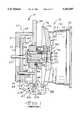
- FIG. 1is a sectional view of a mounting fixture for mounting a wheel upon a lathe and a vehicle wheel in accordance with the prior art.
- FIG. 2is a sectional view of a fixture for mounting a wheel upon a lathe and a vehicle wheel in accordance with the present invention.
- FIG. 3is a sectional view of the mounting fixture shown in FIG. 2 with opened clamp jaws.
- FIG. 1a sectional view of a fixture for mounting a vehicle wheel upon a lathe, generally indicated at 10, in accordance with the prior art.
- fastenerswhich secure components of the mounting fixture 10 to one another are not shown in FIG. 1.
- the mounting fixture 10includes an adapter plate 20 which can be secured to the rotatable spindle of a lathe (not shown) by conventional means.
- the adapter plate 20includes a circular base 21 which has a central circular opening 22 formed therethrough.
- the adapter plate 20also includes a cylindrical sleeve 23 extending axially from the base 21.
- the sleeve 23has a plurality of axial slots 24 (one shown) formed therethrough. The slots are spaced equally about the circumference of the sleeve 24. The purpose of the slots 24 will be explained below.
- the adapter plate 20further carries a plurality of guide pins 25 (one shown) which extend axially from the base 21.
- the mounting fixture 10includes a circular face plate 30 which is secured to the end of the adapter plate sleeve 23.
- the face plate 30has a central circular opening 31 formed therethrough.
- a plurality of radial slots 32(one shown) are formed in the outer edge of the face plate 30.
- the slots 32are spaced equally about the circumference of the face plate 30.
- Each slot 32has a cam pin 33 mounted transversely thereacross. The purpose for the slots 32 and the cam pins 33 will be explained below.
- a plurality of part rests 34are mounted upon the outer surface of the face plate 30.
- the part rests 34are spaced equally about the circumference of the face plate 30.
- the face plate opening 31receives a generally cylindrical center sleeve 35.
- the center sleeve 35has a central axial bore 36 formed therethrough.
- a pilot tube 40is disposed within the center sleeve bore 36.
- the pilot tube 40has a piston bore 41 formed therethrough.
- a counter bore 42is formed in the outer end of the piston bore 41.
- a flange 43is formed on the outer end of the pilot tube 40.
- a first plurality of compression springs 44(one shown) are disposed between the pilot tube flange 43 and the outer end of the center sleeve 35.
- the pilot tube flange 43also carries a plurality of locator pylons 45 (one shown) the purpose for which will be explained below.
- the mounting fixture 10also includes a piston 50 which is disposed within the pilot tube bore 41.
- the piston 50has an outer end 51 which is formed to contact the center portion of a wheel hub.
- the piston outer end 51has a greater diameter than the remainder of the piston 45 and defines a shoulder 52 therebetween.
- a second plurality of compression springs 53are disposed between the piston shoulder 52 and the pilot tube flange 53.
- the mounting fixture 10further includes an axially movable yoke plate 60 which is disposed within the adapter plate sleeve 23.
- the yoke plate 60is circular and has a plurality of guide pin holes 61 formed therethrough. Each of the guide pin holes 61 slidably receives one of the guide pins 25.
- the yoke plate 60also has a plurality of radially extending arms 62 (one shown) which correspond to the adapter plate slots 24. The arms 62 are spaced equally about the circumference of the yoke plate 60 and each arm 62 extends through one of the adapter plate slots 24.
- An actuator bar 63is secured to the center of the yoke plate 60 and extends axially through the adapter plate opening 22. The actuator bar 63 is connected to a conventional means for axially shifting the actuator bar and yoke plate assembly.
- a plurality of cam arms 65are pivotally mounted on the ends of the yoke plate arms 62.
- a first end of each cam armis secured to each yoke plate arm 62 with a pivot pin 66.
- the center portion of each cam arm 65has a generally L-shaped cam slot 67 formed therethrough.
- the cam slots 67have a generally axial first arm 67A and a second arm 67B which is directed in a radially inward direction.
- Each cam slot 67receives a corresponding cam pin 33.
- a removable cam arm jaw 68which is shaped to clamp over a portion of a vehicle wheel rim, is attached to a second end of each cam arm 65.
- the mounting fixture 10is operative for clamping a vehicle wheel 15 to a lathe for machining the wheel 15 to its final shape.
- the vehicle wheel 15includes an annular wheel rim 70 having a circular wheel disc 71 formed across one end thereof.
- the wheel rim 70includes a central drop well 72 and inboard and outboard tire bead seats 73 and 74.
- the outer ends of the wheel rim 70are formed into inboard and outboard tire retaining flanges 75 and 76.
- the wheel disc 71includes a central hub 77 supported within the wheel rim 70 by a plurality of wheel spokes 78 (one shown).
- the hubhas a central pilot hole 79 and a plurality of wheel mounting holes 80 (one shown) formed therethrough.
- the actuator bar 63is axially extended into the adapter plate sleeve 23, axially shifting the yoke plate 60 away from the adapter plate base 21.
- the cam slot 67 in each cam arm 65slides along the corresponding cam pin 33.
- the cam pins 33cooperate with the cam slots 67 to urge the cam arms 65 in an outward radial direction, thereby opening the mounting fixture 10.
- a wheel 15can be mounted upon the mounting fixture 10.
- the wheel hub 77is placed adjacent to the outer end 51 of the piston 50 with the outboard tire bead retaining flange engaging the part rests 34.
- the locator pylons 45are received by corresponding wheel mounting holes 80.
- the actuator bar 63is then retracted, moving the yoke plate 60 axially towards the adapter plate base 21.
- the cam slots 67 in each of the cam arms 65is drawn back over the cam pins 33.
- the cam pins 33cooperate with the cam slots 67 to urge the cam arms 65 in an inward radial direction, thereby causing the jaws 68 to move to a closed position and clamp onto the wheel flange 76.
- the wheel flange 76is drawn firmly against the part rests 34.
- the piston outer end 51is axially shifted by the wheel hub 77, compressing the first and second sets of compression springs 44 and 53.
- the locator pylons 45cooperate with the wheel mounting holes 80 to rotate the wheel.
- wheel 15is shown having a wheel disc 71 located at an end of the wheel rim 70, it will be appreciated that the wheel disc also can be recessed within the wheel rim 70. For such wheels, a different pilot tube and piston having a greater axial length would be substituted for the ones shown in FIG. 1.
- the cam arm jaws 68extend over a portion of the vehicle wheel outboard tire bead seat 74. This prevents machining both bead seats 73 and 74 during a single machining operation. Accordingly, it is necessary to machine one bead seat, remove the wheel 70 from the mounting fixture 10, reverse the wheel 70, remount the wheel 70 on the mounting fixture 10 and then machine the second bead seat. In order to remount the wheel 15 shown in FIG. 1 on the fixture 10, it is necessary to replace pilot tube and piston assembly with a longer assembly which will axially span the inside of the wheel rim 70 to contact the inboard face of the wheel disc 71. Alternately, a second lathe can be used to machine the second tire bead seat. Either procedure is time consuming and can result in non-concentric tire bead seats. Accordingly, it would be desirable to machine both tire bead seats 73 and 74 during a single machining operation.
- the present inventioncontemplates an improved fixture for mounting a vehicle wheel upon a lathe, which is illustrated generally at 90 in the sectional view shown in FIGS. 2 and 3.
- fastenerswhich secure components of the improved mounting fixture 90 to one another are not shown in FIGS. 2 and 3.
- the vehicle wheel 15 described aboveis shown mounted upon the improved mounting fixture 90. Accordingly, portions of the wheel 15 shown in FIGS. 2 and 3 are identified with the same numerical indicators used in FIG. 1.
- the mounting fixture 90includes an adapter plate 95 which can be secured to the rotatable spindle of a lathe (not shown) by conventional means.
- the adapter plate 95includes a circular base 96 which has a central circular opening 97 formed therethrough.
- the adapter plate 95also includes a cylindrical sleeve 98 extending in an axial direction from the base 96.
- a circular face plate 100is secured to an end of the adapter plate sleeve 98.
- the face plate 100has a portion 101 which extends radially beyond the adapter sleeve 98.
- the portion 101has a plurality of guide pin holes 102 (one shown) formed therethrough.
- the guide pin holes 102are equally spaced about the circumference of the face plate 100.
- the face plate 100also has a central circular opening 103 formed therethrough.
- a plurality of axial slots 104extend radially from the opening 103.
- the slots 104are spaced equally about the circumference of the face plate opening 103.
- Each slot 104has a cam pin 105 mounted transversely thereacross.
- a stop block 106is carried on the inner surface of the face plate 100.
- the face plate 100carries a plurality of spacer posts 107 (one shown).
- the spacer posts 107are spaced equally about a circle which is concentric with the face plate opening 103.
- a circular part rest 110is removably secured to the outer ends of the spacer posts 107.
- the part rest 110supports and centers the wheel 15 upon the mounting fixture 90. Accordingly, the part rest 110 is shaped to correspond to a corresponding wheel design.
- the present inventioncontemplates a plurality of interchangeable part rests 110 to allow machining a number of different vehicle wheels.
- the part rest 110includes a circular base 111.
- An annular sleeve 112extends axially from the outer surface of base 111. As shown in FIG. 2, the sleeve 112 contacts a portion of the wheel hub 77 to center the wheel 15 upon the mounting fixture 90.
- the part rest base 111has a plurality of radial slots 113 formed therethrough (one shown). The slots extend outwardly from the center of the part rest 110.
- the part rest base 111also has a threaded drive pin aperture 114 formed therethrough.
- the drive pin aperture 114receives a drive pin 115.
- the drive pin 115extends in an axial direction from the part rest base 111.
- the part rest 110further includes a mounting post 116 extending axially from the center thereof.
- the post 116has a plurality of axial slots 117 formed therein (one shown). Each of the mounting post slots 117 is aligned with a corresponding base slot 113 to form an extension thereof.
- the improved mounting fixture 90also includes an axially movable yoke plate 120 which is disposed within the adapter plate sleeve 98.
- the yoke platehas a plurality of radial slots 121 (one shown) formed therein. The slots are spaced equally about the circumference of the yoke plate 120. Each slot 121 caries a transversely mounted pivot pin 122.
- An actuator bar 123is secured to the center of the yoke plate 120 and extends through the adapter plate opening 97. The actuator bar 123 is connected to a conventional means for axially shifting the actuator bar and yoke plate assembly.
- a plurality of cam arms 125are pivotally mounted on the yoke plate 120.
- a first end of each cam arm 125is secured in one of the yoke plate slots 121 with one of the pivot pins 122.
- the cam arms 125extend axially through corresponding face plate slots 104.
- the center portion of each cam arm 125has a generally L-shaped cam slot 126 formed therethrough.
- the cam slots 126have a generally axial first arm 127 and a second arm 128 which is directed in a radially outward direction.
- Each cam slot 126receives a corresponding cam pin 105.
- a removable cam arm jaw 129is attached to a second end of each cam arm 125.
- the cam arm jaws 129are offset in a radial inward direction to extend through the part rest and mounting post slots 113 and 117. An end of each cam arm jaw 129 extends beyond the part rest post 116 and includes a finger 129A which clamps over a portion of the outboard surface of a vehicle wheel hub 77.
- the improved mounting fixture 90further includes an annular dampening ring having a circular base 130 disposed about the adapter plate sleeve 98.
- the dampening ring base 130carries a plurality of guide pins 131 (one shown) which extend axially therefrom.
- the guide pins 131are spaced equally about a circle which is concentric with the dampening ring 130.
- Each of guide pins 131extends axially through a corresponding face plate guide pin hole 102.
- a spacer sleeve 132 and resilient bushing 133is carried by each guide pin 131 between the dampening ring base 130 and the spring ring.
- the spacer sleeve 132 and bushing 133position the dampening ring axially on the adapter plate sleeve 98.
- One end of each guide pinis secured to the dampening ring base 130 and the other end is secured to an annular spring ring 135.
- the spring ring 135is disposed between the face plate 101 and the part rest 110.
- a plurality of compression springs 136are disposed between the spring ring 135 and the face plate 100. The compression springs 136 urge the spring plate 135 in an axial direction away from the face plate 101, causing the spacer sleeves 132 to compress the bushings 133.
- the actuator bar 123is axially extended into the adapter plate sleeve 98 until the yoke plate 120 contacts the stop block 106. This axially shifts the yoke plate 120 away from the adapter plate base 96 as shown in FIG. 3.
- the cam slot 126 in each cam arm 125slides along the corresponding cam pin 105. Because the second leg 128 of the cam slot 126 is directed radially outward, the cam pins 105 cooperate with the cam slots 126 to urge the cam arms 125 in an inward radial direction, thereby opening the mounting fixture 90 by moving the cam arm jaws 129 and fingers 129A to a released position.
- a wheel 15can be mounted upon the mounting fixture 90.
- the wheel hub 77is placed adjacent to the part rest base 111 with the part rest post 116 and the cam arm jaws 129 extending through the wheel pilot hole 79.
- the part rest annular sleeve 112extends around the circumference of the wheel hub 77, positioning the wheel 15 concentrically upon the fixture 90.
- the drive pin 115is received by one of the wheel mounting holes 80.
- Retraction of the actuator bar 123is begun, moving the yoke plate 120 axially towards the adapter plate base 96. As the yoke plate 120 moves towards the adapter plate base 96, the cam slots 126 in each of the cam arms 125 are drawn back over the cam pins 105.
- the cam pins 105cooperate with the cam slots 126 to urge the cam arms 125 in an outward radial direction, causing the cam arm jaws 129 to move to a closed position and the fingers 129A to clamp onto the outboard surface of the wheel hub 77.
- the wheel 15is moved axially towards the dampening ring sleeve 130A.
- the inboard wheel flange 75engages and presses against the resilient dampening ring sleeve 130A, shifting the dampening ring axially and further compressing the compression springs 136.
- the cam arm jaw fingers 129Afirmly clamp the inboard wheel hub mounting surface against the part rest 110. This supports the outboard end of the wheel 15 while the inboard end of the wheel 15 is supported by the dampening ring sleeve 130A.
- the drive pin 115cooperates with the wheel mounting hole 80 to rotate the wheel 15.
- wheel 15is shown having a wheel disc 71 located at an end of the wheel rim 70, it will be appreciated that the wheel disc also can be recessed within the wheel rim 70.
- alternate spacer posts and another dampening ring sleeve having shorter axial lengthswould be substituted for the ones shown in FIGS. 2 and 3.
- spacer posts and a dampening ring sleeve having a greater axial distancewould be installed on the fixture 90.
- Different wheel hub designscan be accommodated by installing different cam arm jaws 129 and a different part rest 110. This interchangability of parts allows the fixture 90 to be used for multiple wheel designs.
- the cam arm jaws 129 and fingers 129Aclamp onto an interior surface of the wheel 15.
- an interior surface of the inboard end of the wheel 15is supported by the resilient dampening ring sleeve 130A.
- both bead seats 73 and 74are exposed for machining during a single machining operation. This reduces machining time while improving the concentricity of the bead seats 73 and 74.
- FIGS. 2 and 3is illustrative of the invention. Accordingly, the invention can be practiced with a mounting fixture having more or less parts than are shown in FIGS. 2 and 3. Additionally, while the invention has been described as being used to machine the tire bead seats 73 and 74, it will be appreciated that the improved mounting fixture 90 can be used during machining of any or all of the outer surfaces of the wheel rim 70.
- cam arm jawscan be extended in a radial outward direction to pass through the openings in the wheel disc formed between the wheel spokes 78. With such cam arms, the jaw fingers would be directed radially inward and would engage the circumference of the wheel hub outboard surface.
Landscapes
- Engineering & Computer Science (AREA)
- Mechanical Engineering (AREA)
- Turning (AREA)
Abstract
Description
Claims (13)
Priority Applications (1)
| Application Number | Priority Date | Filing Date | Title |
|---|---|---|---|
| US08/357,685US5562007A (en) | 1994-12-16 | 1994-12-16 | Wheel mounting fixture for double bead seat machining |
Applications Claiming Priority (1)
| Application Number | Priority Date | Filing Date | Title |
|---|---|---|---|
| US08/357,685US5562007A (en) | 1994-12-16 | 1994-12-16 | Wheel mounting fixture for double bead seat machining |
Publications (1)
| Publication Number | Publication Date |
|---|---|
| US5562007Atrue US5562007A (en) | 1996-10-08 |
Family
ID=23406619
Family Applications (1)
| Application Number | Title | Priority Date | Filing Date |
|---|---|---|---|
| US08/357,685Expired - Fee RelatedUS5562007A (en) | 1994-12-16 | 1994-12-16 | Wheel mounting fixture for double bead seat machining |
Country Status (1)
| Country | Link |
|---|---|
| US (1) | US5562007A (en) |
Cited By (27)
| Publication number | Priority date | Publication date | Assignee | Title |
|---|---|---|---|---|
| US5797605A (en)* | 1995-12-22 | 1998-08-25 | The Gleason Works | Workholding apparatus |
| US6126174A (en)* | 1997-10-13 | 2000-10-03 | Hayes Lemmerz International, Inc. | Apparatus for machining vehicle wheel bead seats |
| US6186517B1 (en)* | 1996-12-24 | 2001-02-13 | Michel Beffrieu | Pilot tool for centering and clamping |
| US6199873B1 (en)* | 1998-07-27 | 2001-03-13 | Genus Technologies | Device for centering and gripping, particularly of automobile bodywork parts |
| WO2002098589A1 (en)* | 2001-06-06 | 2002-12-12 | Bbs - Riva S.P.A. | Coupling device particularly for vehicle wheels undergoing surface finishing |
| US6502834B1 (en)* | 2000-11-07 | 2003-01-07 | Howa Machinery, Ltd. | Holding chuck for a tire-wheel with a chatter-suppressing device |
| US20030160402A1 (en)* | 2002-02-22 | 2003-08-28 | Patterson Alan C. | Anti-deflection tooling |
| US20060042091A1 (en)* | 2004-09-02 | 2006-03-02 | Northtech Workholding | Method and apparatus for processing/machining a vehicle wheel/rim preform |
| US20060082075A1 (en)* | 2004-10-18 | 2006-04-20 | Gatton Geoffrey L | Wheel chuck with counterweighted jaws |
| US7185573B1 (en) | 2005-02-18 | 2007-03-06 | Hayes Lemmerz International, Inc. | Vacuum wheel chuck |
| US7204493B1 (en) | 2004-06-03 | 2007-04-17 | Hayes Lemmerz International, Inc. | Lathe chuck with stepped jaws |
| US7243584B1 (en) | 2005-03-31 | 2007-07-17 | Hayes Lemmerz International, Inc. | Mask for a wheel lathe chuck that prevents whip chip |
| US20080011130A1 (en)* | 2004-04-08 | 2008-01-17 | Smyth Larry C | Method For Clamping And Turning A Vehicle Wheel Shape |
| JP2009066679A (en)* | 2007-09-11 | 2009-04-02 | Howa Mach Ltd | Tire wheel vibration proof method and device for tire wheel holding chuck |
| US20100090419A1 (en)* | 2005-08-05 | 2010-04-15 | Kitagawa Iron Works Co., Ltd | Gripping Method for Turbocharger Housing and Work Gripping Device |
| US7703206B1 (en) | 2005-03-01 | 2010-04-27 | Hayes Lemmerz International, Inc. | Universal wheel pylon |
| US20110110103A1 (en)* | 2008-04-23 | 2011-05-12 | Clay Paky S.P.A. | Effects wheel assembly for a light fixture, in particular a stage light fixture |
| JP2012000747A (en)* | 2010-05-20 | 2012-01-05 | Teikoku Chuck Kk | Light alloy wheel chucking device |
| WO2012002948A1 (en)* | 2010-06-30 | 2012-01-05 | Volvo Group North America, Llc | Wheel cover and mounting device |
| US20150241294A1 (en)* | 2012-09-10 | 2015-08-27 | Haweka Ag | Clamping device having hub centring |
| CN105057699A (en)* | 2015-07-31 | 2015-11-18 | 梧州奥卡光学仪器有限公司 | Machining method of microscope arm |
| US20170209969A1 (en)* | 2016-01-22 | 2017-07-27 | Citic Dicastal Co., Ltd | Lathe Chuck for Aluminum Alloy Hubs |
| CN107697630A (en)* | 2017-09-28 | 2018-02-16 | 镇江威尔耐车轮制造有限公司 | A kind of kappa wheel cutting fixture |
| US10029314B1 (en)* | 2017-01-25 | 2018-07-24 | Yeong Chin Machinery Industries Co., Ltd. | Automatic wheel rim positioning and clamping tool |
| CN109719317A (en)* | 2018-12-31 | 2019-05-07 | 保定向阳航空精密机械有限公司 | A kind of self-centering disk mandrel of fluid pressure type |
| CN112828635A (en)* | 2020-12-31 | 2021-05-25 | 宁波德玛智能机械有限公司 | Clamp for hub machining |
| US11559868B2 (en)* | 2019-03-26 | 2023-01-24 | Citic Dicastal Co., Ltd. | Wheel machining equipment |
Citations (6)
| Publication number | Priority date | Publication date | Assignee | Title |
|---|---|---|---|---|
| US1959081A (en)* | 1932-03-21 | 1934-05-15 | Kelsey Hayes Wheel Corp | Chuck |
| US2194936A (en)* | 1936-03-25 | 1940-03-26 | Harley C Loney Company | Wheel balancing apparatus |
| US2557726A (en)* | 1948-09-07 | 1951-06-19 | Kelsey Hayes Wheel Co | Work holding chuck |
| US3131946A (en)* | 1962-01-02 | 1964-05-05 | Budd Co | Draw-bar actuated centering device |
| US3323808A (en)* | 1964-10-28 | 1967-06-06 | Budd Co | Workpiece clamping means |
| US5464233A (en)* | 1993-03-08 | 1995-11-07 | Howa Machinery Ltd. | Finger chuck for use with machine tool |
- 1994
- 1994-12-16USUS08/357,685patent/US5562007A/ennot_activeExpired - Fee Related
Patent Citations (6)
| Publication number | Priority date | Publication date | Assignee | Title |
|---|---|---|---|---|
| US1959081A (en)* | 1932-03-21 | 1934-05-15 | Kelsey Hayes Wheel Corp | Chuck |
| US2194936A (en)* | 1936-03-25 | 1940-03-26 | Harley C Loney Company | Wheel balancing apparatus |
| US2557726A (en)* | 1948-09-07 | 1951-06-19 | Kelsey Hayes Wheel Co | Work holding chuck |
| US3131946A (en)* | 1962-01-02 | 1964-05-05 | Budd Co | Draw-bar actuated centering device |
| US3323808A (en)* | 1964-10-28 | 1967-06-06 | Budd Co | Workpiece clamping means |
| US5464233A (en)* | 1993-03-08 | 1995-11-07 | Howa Machinery Ltd. | Finger chuck for use with machine tool |
Cited By (39)
| Publication number | Priority date | Publication date | Assignee | Title |
|---|---|---|---|---|
| US5797605A (en)* | 1995-12-22 | 1998-08-25 | The Gleason Works | Workholding apparatus |
| US6186517B1 (en)* | 1996-12-24 | 2001-02-13 | Michel Beffrieu | Pilot tool for centering and clamping |
| US6126174A (en)* | 1997-10-13 | 2000-10-03 | Hayes Lemmerz International, Inc. | Apparatus for machining vehicle wheel bead seats |
| US6199873B1 (en)* | 1998-07-27 | 2001-03-13 | Genus Technologies | Device for centering and gripping, particularly of automobile bodywork parts |
| US6502834B1 (en)* | 2000-11-07 | 2003-01-07 | Howa Machinery, Ltd. | Holding chuck for a tire-wheel with a chatter-suppressing device |
| US20030143046A1 (en)* | 2001-06-06 | 2003-07-31 | Baumgartner Heinrich Georg | Coupling device particularly for vehicle wheels undergoing surface finishing |
| US6862785B2 (en) | 2001-06-06 | 2005-03-08 | Bbs-Riva S.P.A. | Coupling device particularly for vehicle wheels undergoing surface finishing |
| WO2002098589A1 (en)* | 2001-06-06 | 2002-12-12 | Bbs - Riva S.P.A. | Coupling device particularly for vehicle wheels undergoing surface finishing |
| CN1319687C (en)* | 2001-06-06 | 2007-06-06 | Bbs-丽伐股份公司 | Coupling device particularly for vehicle wheels undergoing surface finishing |
| US20030160402A1 (en)* | 2002-02-22 | 2003-08-28 | Patterson Alan C. | Anti-deflection tooling |
| US6918599B2 (en)* | 2002-02-22 | 2005-07-19 | Alan C. Patterson | Anti-deflection tooling |
| US20080011130A1 (en)* | 2004-04-08 | 2008-01-17 | Smyth Larry C | Method For Clamping And Turning A Vehicle Wheel Shape |
| US7204493B1 (en) | 2004-06-03 | 2007-04-17 | Hayes Lemmerz International, Inc. | Lathe chuck with stepped jaws |
| US7415766B2 (en)* | 2004-09-02 | 2008-08-26 | Northtech Workholding | Method and apparatus for processing/machining a vehicle wheel/rim preform |
| US20060042091A1 (en)* | 2004-09-02 | 2006-03-02 | Northtech Workholding | Method and apparatus for processing/machining a vehicle wheel/rim preform |
| US20060082075A1 (en)* | 2004-10-18 | 2006-04-20 | Gatton Geoffrey L | Wheel chuck with counterweighted jaws |
| US7198277B2 (en) | 2004-10-18 | 2007-04-03 | Hayes Lemmerz International, Inc. | Wheel chuck with counterweighted jaws |
| US7185573B1 (en) | 2005-02-18 | 2007-03-06 | Hayes Lemmerz International, Inc. | Vacuum wheel chuck |
| US7703206B1 (en) | 2005-03-01 | 2010-04-27 | Hayes Lemmerz International, Inc. | Universal wheel pylon |
| US7243584B1 (en) | 2005-03-31 | 2007-07-17 | Hayes Lemmerz International, Inc. | Mask for a wheel lathe chuck that prevents whip chip |
| US8220805B2 (en)* | 2005-08-05 | 2012-07-17 | Kitagawa Iron Works Co., Ltd. | Gripping method for turbocharger housing and work gripping device |
| US20100090419A1 (en)* | 2005-08-05 | 2010-04-15 | Kitagawa Iron Works Co., Ltd | Gripping Method for Turbocharger Housing and Work Gripping Device |
| JP4913055B2 (en)* | 2005-08-05 | 2012-04-11 | 株式会社北川鉄工所 | Method of gripping turbocharger housing and workpiece gripping device |
| KR101346078B1 (en)* | 2005-08-05 | 2013-12-31 | 가부시키가이샤 기타가와 뎃꼬쇼 | Work holding device of holding turbocharger housing |
| JP2009066679A (en)* | 2007-09-11 | 2009-04-02 | Howa Mach Ltd | Tire wheel vibration proof method and device for tire wheel holding chuck |
| US20110110103A1 (en)* | 2008-04-23 | 2011-05-12 | Clay Paky S.P.A. | Effects wheel assembly for a light fixture, in particular a stage light fixture |
| US8944646B2 (en)* | 2008-04-23 | 2015-02-03 | Clay Paky S.P.A. | Effects wheel assembly for a light fixture, in particular a stage light fixture |
| JP2012000747A (en)* | 2010-05-20 | 2012-01-05 | Teikoku Chuck Kk | Light alloy wheel chucking device |
| WO2012002948A1 (en)* | 2010-06-30 | 2012-01-05 | Volvo Group North America, Llc | Wheel cover and mounting device |
| US20150241294A1 (en)* | 2012-09-10 | 2015-08-27 | Haweka Ag | Clamping device having hub centring |
| US10132708B2 (en)* | 2012-09-10 | 2018-11-20 | Haweka Ag | Clamping device having hub centering |
| CN105057699A (en)* | 2015-07-31 | 2015-11-18 | 梧州奥卡光学仪器有限公司 | Machining method of microscope arm |
| CN105057699B (en)* | 2015-07-31 | 2017-07-07 | 梧州奥卡光学仪器有限公司 | The processing method of handel |
| US20170209969A1 (en)* | 2016-01-22 | 2017-07-27 | Citic Dicastal Co., Ltd | Lathe Chuck for Aluminum Alloy Hubs |
| US10029314B1 (en)* | 2017-01-25 | 2018-07-24 | Yeong Chin Machinery Industries Co., Ltd. | Automatic wheel rim positioning and clamping tool |
| CN107697630A (en)* | 2017-09-28 | 2018-02-16 | 镇江威尔耐车轮制造有限公司 | A kind of kappa wheel cutting fixture |
| CN109719317A (en)* | 2018-12-31 | 2019-05-07 | 保定向阳航空精密机械有限公司 | A kind of self-centering disk mandrel of fluid pressure type |
| US11559868B2 (en)* | 2019-03-26 | 2023-01-24 | Citic Dicastal Co., Ltd. | Wheel machining equipment |
| CN112828635A (en)* | 2020-12-31 | 2021-05-25 | 宁波德玛智能机械有限公司 | Clamp for hub machining |
Similar Documents
| Publication | Publication Date | Title |
|---|---|---|
| US5562007A (en) | Wheel mounting fixture for double bead seat machining | |
| US6126174A (en) | Apparatus for machining vehicle wheel bead seats | |
| US7204493B1 (en) | Lathe chuck with stepped jaws | |
| US4083672A (en) | Automatic hub and apparatus for disassembly of the hub | |
| EP1439928B9 (en) | Coupling device particularly for vehicle wheels undergoing surface finishing | |
| US5848795A (en) | Front part replacement type finger chuck | |
| US6371468B1 (en) | Universal workpiece holder | |
| US5397135A (en) | Expanding collet assembly | |
| US20080011130A1 (en) | Method For Clamping And Turning A Vehicle Wheel Shape | |
| US3131946A (en) | Draw-bar actuated centering device | |
| US4067098A (en) | Method of manufacturing brake drums | |
| US7703206B1 (en) | Universal wheel pylon | |
| EP0391834B1 (en) | Tire bead setter apparatus and method | |
| WO1998003281A1 (en) | Process for spin forming a vehicle wheel | |
| US3580043A (en) | Wheel rounding machine | |
| EP0153118B1 (en) | Setting-up of workpieces for machining | |
| US6233992B1 (en) | Multi-station rotary endform machine | |
| US4293358A (en) | Method and apparatus for accurately positioning a bead bundle | |
| US5556114A (en) | Hydraulic expanding and contracting mandrel | |
| CN110733293B (en) | A kind of expandable wheel rim positioning assembly mold | |
| CN220837983U (en) | Hub machining clamp | |
| US4726214A (en) | Shrink forming apparatus | |
| SU1047608A2 (en) | Expansion mandrel | |
| CN220463063U (en) | Auxiliary device for machine tool machining | |
| SU1412844A1 (en) | Male die for machining edges of round holes |
Legal Events
| Date | Code | Title | Description |
|---|---|---|---|
| AS | Assignment | Owner name:HAYES WHEELS INTERNATIONAL, INC., MICHIGAN Free format text:ASSIGNMENT OF ASSIGNORS INTEREST;ASSIGNOR:SEYMOUR, JAMES B.;REEL/FRAME:007287/0288 Effective date:19941215 | |
| AS | Assignment | Owner name:CANADIAN IMPERIAL BANK OF COMMERCE (AS AGENT), NEW Free format text:SECURITY AGREEMENT;ASSIGNORS:HAYES WHEELS INTERNATIONAL, INC;MOTOR WHEEL CORPORATION;MWC ACQUISTION SUB, INC, (D/B/A TRU-RURN CORPORATION.;REEL/FRAME:008104/0067 Effective date:19960627 | |
| FPAY | Fee payment | Year of fee payment:4 | |
| AS | Assignment | Owner name:CANADIAN IMPERIAL BANK OF COMMERCE AS ADMINISTRATI Free format text:SECURITY AGREEMENT;ASSIGNOR:HAYES LEMMERZ INTERNATIONAL, INC.;REEL/FRAME:012211/0425 Effective date:20010702 | |
| AS | Assignment | Owner name:CITICORP NORTH AMERICA, INC., AS "AGENT", NEW YORK Free format text:SECURITY AGREEMENT;ASSIGNORS:HLI OPERATING COMPANY, INC.;HAYES LEMMERZ INTERNATIONAL, INC.;HAYES LEMMERZ INTERNATIONAL-OHIO, INC.;AND OTHERS;REEL/FRAME:014178/0834 Effective date:20030603 | |
| FEPP | Fee payment procedure | Free format text:PAYOR NUMBER ASSIGNED (ORIGINAL EVENT CODE: ASPN); ENTITY STATUS OF PATENT OWNER: LARGE ENTITY | |
| FPAY | Fee payment | Year of fee payment:8 | |
| AS | Assignment | Owner name:CITICORP NORTH AMERICA, INC.,NEW YORK Free format text:SECURITY AGREEMENT;ASSIGNORS:HAYES-LEMMERZ INTERNATIONAL, INC.;HLI OPERATING COMPANY, INC.;HAYES-LEMMERZ INTERNATIONAL-EQUIPMENT AND ENGINEERING, INC.;AND OTHERS;REEL/FRAME:015991/0242 Effective date:20050411 Owner name:CITICORP NORTH AMERICA, INC., NEW YORK Free format text:SECURITY AGREEMENT;ASSIGNORS:HAYES-LEMMERZ INTERNATIONAL, INC.;HLI OPERATING COMPANY, INC.;HAYES-LEMMERZ INTERNATIONAL-EQUIPMENT AND ENGINEERING, INC.;AND OTHERS;REEL/FRAME:015991/0242 Effective date:20050411 | |
| AS | Assignment | Owner name:HAYES LEMMERZ INTERNATIONAL, INC., MICHIGAN Free format text:TERMINATION AND RELEASE OF SECURITY INTEREST IN PATENT RIGHTS (PREVIOUSLY RECORDED AT REEL 12211 FRAME 0425);ASSIGNOR:CANADIAN IMPERIAL BANK OF COMMERCE, AS ADMINISTRATIVE AGENT;REEL/FRAME:016996/0161 Effective date:20051220 | |
| REMI | Maintenance fee reminder mailed | ||
| LAPS | Lapse for failure to pay maintenance fees | ||
| STCH | Information on status: patent discontinuation | Free format text:PATENT EXPIRED DUE TO NONPAYMENT OF MAINTENANCE FEES UNDER 37 CFR 1.362 | |
| FP | Lapsed due to failure to pay maintenance fee | Effective date:20081008 |