US5561952A - Combination skylight/static ventilator - Google Patents
Combination skylight/static ventilatorDownload PDFInfo
- Publication number
- US5561952A US5561952AUS08/225,554US22555494AUS5561952AUS 5561952 AUS5561952 AUS 5561952AUS 22555494 AUS22555494 AUS 22555494AUS 5561952 AUS5561952 AUS 5561952A
- Authority
- US
- United States
- Prior art keywords
- hood
- conduit
- flange
- roof
- skylight
- Prior art date
- Legal status (The legal status is an assumption and is not a legal conclusion. Google has not performed a legal analysis and makes no representation as to the accuracy of the status listed.)
- Expired - Fee Related
Links
- 230000003068static effectEffects0.000titleclaimsdescription11
- 238000009423ventilationMethods0.000claimsdescription3
- 230000008595infiltrationEffects0.000abstractdescription3
- 238000001764infiltrationMethods0.000abstractdescription3
- 238000013022ventingMethods0.000abstractdescription3
- 238000009434installationMethods0.000abstractdescription2
- XLYOFNOQVPJJNP-UHFFFAOYSA-NwaterSubstancesOXLYOFNOQVPJJNP-UHFFFAOYSA-N0.000abstract1
- 239000000463materialSubstances0.000description14
- 230000035515penetrationEffects0.000description5
- 241000607479Yersinia pestisSpecies0.000description4
- 238000004891communicationMethods0.000description4
- 230000008901benefitEffects0.000description3
- 238000001556precipitationMethods0.000description3
- 239000000758substrateSubstances0.000description3
- 230000004075alterationEffects0.000description2
- 239000002131composite materialSubstances0.000description2
- 238000013461designMethods0.000description2
- 229910003460diamondInorganic materials0.000description2
- 239000010432diamondSubstances0.000description2
- 230000005484gravityEffects0.000description2
- 238000000034methodMethods0.000description2
- 239000002023woodSubstances0.000description2
- 230000004888barrier functionEffects0.000description1
- 230000008859changeEffects0.000description1
- 230000008602contractionEffects0.000description1
- 230000000694effectsEffects0.000description1
- 239000002657fibrous materialSubstances0.000description1
- 239000012530fluidSubstances0.000description1
- 239000003517fumeSubstances0.000description1
- 239000011521glassSubstances0.000description1
- 238000005286illuminationMethods0.000description1
- 238000009413insulationMethods0.000description1
- 239000002184metalSubstances0.000description1
- 239000007769metal materialSubstances0.000description1
- 239000000203mixtureSubstances0.000description1
- 230000004048modificationEffects0.000description1
- 238000012986modificationMethods0.000description1
- 229920000642polymerPolymers0.000description1
- 230000008439repair processEffects0.000description1
- 230000002940repellentEffects0.000description1
- 239000005871repellentSubstances0.000description1
- 230000001846repelling effectEffects0.000description1
- 230000000630rising effectEffects0.000description1
- 239000007787solidSubstances0.000description1
- 230000007704transitionEffects0.000description1
Images


Classifications
- E—FIXED CONSTRUCTIONS
- E04—BUILDING
- E04D—ROOF COVERINGS; SKY-LIGHTS; GUTTERS; ROOF-WORKING TOOLS
- E04D13/00—Special arrangements or devices in connection with roof coverings; Protection against birds; Roof drainage ; Sky-lights
- E04D13/03—Sky-lights; Domes; Ventilating sky-lights
- E04D13/0325—Sky-lights; Domes; Ventilating sky-lights provided with ventilating means
- E—FIXED CONSTRUCTIONS
- E04—BUILDING
- E04D—ROOF COVERINGS; SKY-LIGHTS; GUTTERS; ROOF-WORKING TOOLS
- E04D13/00—Special arrangements or devices in connection with roof coverings; Protection against birds; Roof drainage ; Sky-lights
- E04D13/17—Ventilation of roof coverings not otherwise provided for
- F—MECHANICAL ENGINEERING; LIGHTING; HEATING; WEAPONS; BLASTING
- F24—HEATING; RANGES; VENTILATING
- F24F—AIR-CONDITIONING; AIR-HUMIDIFICATION; VENTILATION; USE OF AIR CURRENTS FOR SCREENING
- F24F7/00—Ventilation
- F24F7/02—Roof ventilation
- F—MECHANICAL ENGINEERING; LIGHTING; HEATING; WEAPONS; BLASTING
- F24—HEATING; RANGES; VENTILATING
- F24F—AIR-CONDITIONING; AIR-HUMIDIFICATION; VENTILATION; USE OF AIR CURRENTS FOR SCREENING
- F24F2221/00—Details or features not otherwise provided for
- F24F2221/52—Weather protecting means, e.g. against wind, rain or snow
Definitions
- This inventionrelates in general to building products used on a pitched roofing surface to facilitate static ventilation of an attic space.
- the inventionalso relates to the passive admittance of sunlight into said attic space.
- a static roof ventilator(more commonly referred to as a "pot vent”) is incorporated into the roof deck to dissipate moisture and vapor from the attic space to the outside of the dwelling.
- the moistureregardless of the numerous origins, left unchecked, will build up and cause extensive damage within the structure. Pot vents also work to lower heat buildup during the summer months.
- pot ventsconsist of three main components, a flange or base portion, a conduit portion, and a hood portion.
- the flangeis nailed to the roof deck over a similar sized hole as with the conduit portion.
- the leading edge of the flangeis positioned over a course of shingles, while additional courses are laid over the flange and cut to fit around the conduit.
- the hood portionwhich is rigidly attached to the flange, prevents moisture penetration in most cases.
- wind driven rain and snowtend to circumvent the infra-structure of the vent causing interior damage.
- Another common problem with pot ventsis moisture seeping in around the conduit and following the now hidden tops of the shingles capillary fashion, and drips into the attic space again causing interior damage.
- pot ventsAn additional problem with pot vents is bird nesting and pest infiltration.
- the hood of the pot ventcreates a warm nest area for birds due to the thermal exhaust.
- some manufacturersincorporate a mesh screen. In many cases, it was found that not only did the screen fail, the birds actually used it to make their nest.
- pot ventsWhile another problem with pot vents is the aesthetic value once they are installed to a roof surface, many dwelling owners complain about the boxy square appearance of the vent. It is on the authority of the inventor that pot vent design has not significantly changed in the last 50 years.
- Skylights in generalare installed on dwellings having a finished living area.
- the skylightlets in sunlight to the living area thereby reducing the need for electric light.
- Skylights in generalare very expensive, both to purchase, and expensive to have them installed.
- Some skylightsare inexpensive but constantly leak costing large sums of money to repair structural damage due to rotting wood.
- Skylightsalso have to be finished off from the inside of the home. This work requires a professional, and is normally too complicated for the average homeowner to install.
- this inventorhas a new and useful invention having a main object of providing an inexpensive ventilator having a greater moisture and heat dissipating means while allowing the free introduction of sunlight into the dwelling. While attics are not visited often, they are used to store objects. Since there is a need to supply a lighting means to an attic, the free passage of light through a fully functional ventilator gives the present invention a new and useful purpose. Those who work out in the garage area have a great need to vent the work area of fumes. By getting a return of sunlight at the same value, the garage user can more efficiently make use of utility resources. The same objects apply to farm and ranch structures.
- Another object of the present inventionis to provide an installer with a two-piece ventilator which has the flange/conduit portion being installed first to the roof, and because the hood portion is multi-positional, has said hood portion snapped into place either square to the eaves, or diamond fashion, which would be consistent with a hip-roof design.
- the continued object of said hoodis also to provide the skylighting function by incorporating a partially translucent upper surface which terminates into equally louvered walls.
- Yet another object of the present inventionis to provide an outer and inner flange of the skylight that can be simply installed without having to finish off the trim work typically done to the interior to facilitate the addition of such skylights to an interior ceiling.
- This objectis met by having both flange members telescopingly communicate with each other such that regardless of the thickness of the cathedral ceiling, rafter, and roof deck structure, one collar of each flange will inner-lap the other thereby concealing the inner-structure of the above mentioned roof-rafter-ceiling assembly, which is unsightly.
- This object of the present inventionwill save the user a large sum over installing the prior art.
- a combination static ventilator and a passive skylightfor use on pitched roof surfaces.
- Said roof surfacesare most commonly encountered in residential architecture, as well as non-residential dwellings having a pitched roof surface.
- the present inventionconsists of a two-piece ventilator/skylight.
- the componentsare formed from a UV stabilized composite material, and are installed to a pitched roof surface greater than a 3/12 ratio.
- the first componentcomprises a flange portion with a centrally extruding conduit.
- the conduitgenerally accounts for up to 60% of the surface area of the flange, and is a major factor in determining the net free area of the ventilator.
- an aperture of equal circumferenceis cut through the roof surface at the desired location for the vent.
- the roofing materialsare installed, and using common ventilator installation methods, the flange/conduit component is rigidly fastened in place over said cut hole in the roof surface.
- Located along the top perimeter of the conduitare a plurality of equally displaced indentures that terminate at a designated point down the outer wall portion of the conduit. These indentures are mated to receive a similar plurality of support studs located along the underside of the hood portion of the present invention.
- the hood portion of the embodimenthas a generally rectangular top surface with a circular translucent oriel centrally disposed thereat.
- the orielis in direct alignment with the conduit thereby allowing sunlight to illuminate the also now vented interior space.
- Located at the termination of the rectangular hoodare downwardly sloped wall members which allow the normal passage of air through a plurality of louver openings located thereon.
- the louversrestrict the passage of moisture, however, by deflecting it away from the conduit opening once the wind or gravity driven moisture enters the air exchange area.
- the aforementioned studshaving a snap-locking feature matable to the nubular perimeter of the conduit, rigidly place the hood component of the present invention at a predetermined elevation.
- Said studsterminate at the point of communication between the oriel and conduit so as not to affect the inflow of light.
- the studsoriginate from a cylinder extending downward from the underside of the rectangular top portion of the hood to a point below the elevation of the conduit.
- Said cylinderhaving a greater diameter than the conduit, allows air altered travel either in or out of the structure, but causes unwanted moisture to be dumped as it can't make the alteration due to the gravitational pull in the baffle area.
- a meshis incorporated between the cylinder and conduit opening referred to as the free area.
- Said meshcan be formed from a composite material or from a metallic substance.
- the components of the preferred embodimentcan be joined either square to the eave, or the hood can be rotated 45% and rigidly snapped into place thereby creating a diamond appearance. This allows the installer greater mobility in designing the roof system.
- One advantageis the ability to install the shingles in closer to the conduit. This will hinder the lateral penetration of moisture.
- the prior arthas a rigidly attached hood mounted to the flange away from the conduit, and the shingle, or roofing material, must be notched to fit around the hood.
- Another advantageis being able to install the highly visible hood portion at the end of the roof work at hand so as to prevent marring and damage.
- a solid flange having a centrally disposed orielis installed over a pre-cut aperture in a pitched roof surface.
- the embodimentacts as a skylight only.
- pot ventsare removed permanently to facilitate a new ventilation system, such as continuous eave and ridge vent. Instead of removing many shingles to replace the wood over the vent hole, one simply loosens the shingles around the hole and slides in the translucent flange.
- Another embodiment of the present inventioncomprises a set of the aforementioned skylight only features, only these flanges have collars extending, one inward from the designated roof flange, and one outward from the now designated ceiling flange.
- the collarstelescopingly communicate, with the ceiling flange collar residing inside the dominant roof flange collar.
- the roof flangeis fastened to the roof after a hole has been cut into the substrate to accommodate the collar. This automatically places the oriel in alignment with the ceiling flange oriel. Shingles are then installed using existing roofing methods, which are compatible with all the embodiments of the present invention. From the inside of the dwelling the ceiling flange is set allowing the subordinate collar penetration into the dominant roof flange collar.
- the flange of the ceiling memberis then fastened to the ceiling material. Due to the wide base area of the ceiling flange, the hole cut into the ceiling to allow the collar entry does not have to be precise. It is foreseen that the ceiling material could be installed over the ceiling flange to make the embodiment flush with the rest of the ceiling.
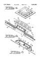
- FIG. 1is a perspective view of a preferred embodiment of the invention installed on a pitched roof surface.
- the present inventionis shown in conjunction with the most common roofing material, a standard three-tab composition shingle.
- FIG. 2is a side elevation, in partial cross-section, of the embodiment showing the flange/conduit portion in relation to the oriel/hood.
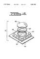
- FIG. 3is a perspective view of the embodiment showing the elevation of the oriel/hood to the flange base. Also viewed is an embodiment of the louver configuration.
- FIG. 4is a dimensional perspective view of the embodiment as it would appear once the components are assembled.
- FIG. 5is a side elevation, in partial cross-section, of the preferred embodiment, slightly exploded. As viewed, an aperture is made into the roof deck consistent with the aperture of the conduit. The oriel/hood is shown prior to being mated to the flange/base portion.
- FIG. 6is a side elevation, in partial cross-section, of the preferred embodiment showing the support fins as in communication with guides located around the perimeter of the conduit.
- FIG. 7is an enlarged cutaway view, in partial cross-section, of the support fin structure of the hood, as affixed to the conduit.
- FIG. 8is a cutaway perspective view of an additional embodiment of the present invention. As viewed, the embodiment of the oriel/hood portion is installed as a skylight. The view does not include the roofing material.
- FIG. 9is a top view, in cross-section, of the preferred embodiment as would be installed square to the eave.
- the phantom linesshow the embodiment installed diagonal to the eave by rotating the hood 45%.
- FIG. 10is a cutaway perspective of the pest repellent means as attached to the collar of the oriel/hood and to the top perimeter of the conduit.
- FIG. 11is a top perspective view of the preferred embodiment as installed diagonally.
- FIG. 12is an exploded view of a metallic embodiment of the present invention depicting a means for securing a skylight feature into the ventilator.
- FIG. 13is a fragmentary cutaway view, in partial cross-section, of the roof flange collar in communication with the ceiling flange collar. The view is slightly exploded to better illustrate the roofing material and the ceiling material.
- FIG. 14is a perspective view of the roof skylight having a finished ceiling flange member.
- FIG. 1shows the present invention 10 installed on a pitched roof 30.
- the base flange 22 of the invention 10is rigidly nailed communicatingly with a roofing material 31 so as to allow precipitation to positively wash around the invention 10.
- Friction fitted to the base flange 22is a hood component 24 which deflects precipitation out and downward from the invention 10.
- Centrally located through the top portion of the hood 24is an oriel 15 which allows photonic penetration into the interior of a structure.
- FIG. 2shows the base flange 22 in relation to the hood 24 elevation.
- a cylindrical conduit 23Centrally extending outward from the base flange 22 is a cylindrical conduit 23 which terminates at a predetermined elevation within the collar 26 section of the hood 22. Said elevation allows air to travel through the infrastructure of the present invention 10 and discharge from apertures located in the sloped walls 18 of the hood 24, and into the open.
- An oriel 15is displaced, generally having a similar diameter as the conduit 23, thereby allowing sunlight to illuminate the area also now vented.
- FIG. 3shows the invention 10, having a base flange 22 with a conduit 23 centrally disposed thereon, and connected internally to a hood member 24 for a purpose of venting a fluid through louvers 17 in the hood 24, and allowing sunlight penetration through an oriel 15 located within the top planer surface of said hood 24.
- FIG. 4shows the present invention 10 with the base/flange portion 22 mated to the hood/oriel member 24.
- FIG. 5shows a pitched roof substrate 46 having an aperture 37 cut there through to serve as a vent.
- roofing materials 54are installed and notched around said aperture 37.
- the base/flange 22, having a conduit 23 extend outward therefrom,is rigidly fastened through the roofing material 54 and into the substratum 46.
- the conduit 23is generally in line with the aperture 37 thereby fixing the "net free flow" of air through the base/flange 22.
- a nub 32At the termination of the conduit 23 is a nub 32.
- Peripherally displaced around the conduit 23, and extending to a midpoint of the conduit 23,are an equal and opposite number of guides 33 which receive support/lock studs 34 (as seen in FIG. 6).
- the hood/oriel member 24is pressed down over the conduit 23 until the locking is complete.
- hood 24When the hood 24 is rigidly in place, said hood 24 will always be fixed at a set elevation.
- inverted deflector skirts 19At the termination of the wall structure are inverted deflector skirts 19 which also displace wind and precipitation uplift.
- oriel 15Centrally located through the top of the hood 24 is an oriel 15 which is in communication first with conduit 23 and the roof aperture 37 thereby allowing for the solar illumination of the also now vented interior.
- the embodiment 10comprises a top hood 24 having a plurality of walls 18 which terminate with an equal number of skirts 19.
- an oriel 15is aligned to the conduit 23 thereby creating a skylight.
- the hood 24is rigidly elevated by a plurality of supporting/locking studs 34 which snap in place over a nub 33 located at the top perimeter of the conduit 23.
- Said support/lock studsoriginate from a collar 26 within the hood 24.
- Said support/lock studs 34are controlled from radial deviation by a plurality of guides 33 located around the outer wall of the conduit 23.
- FIG. 7is an enlarged detail of the support/locking studs 34.
- the present invention 10comprises a first portion, the base/flange 22 and a second portion of the hood 24.
- the studs 34are aligned to grooves 33.
- Said studs 34have a notch 35 located at the corner.
- the mouth of the notch 35is slightly narrower than the width of the nub 32 located atop the conduit 23.
- the mouth of the notch 35is forced to expand over the nub 32 and contracts once it is seated.
- the contraction of the notch 35is what locks the two components in place thereby automatically aligning the oriel 15 to the conduit 23 opening.
- Situated around the termination of the collar 26is a lip 36 which helps to deflect infiltrated moisture away from entry through the space between the support/lock studs 34.
- FIG. 8shows an additional embodiment of the present invention whereas a skylight 40 comprises a flange 42 having an oriel 44 centrally displaced thereon.
- the oriel 44is mated to a similar sized opening 37 in the roof deck 56.
- the hood 24is installed square to the ground by having a plurality of studs 34 lock onto a nub 32 located atop the conduit 23.
- the studs 34extend from a collar 26 located centrally within the walls 18 and are prevented from lateral movement by a plurality of guides 33 displaced around the outer wall of the conduit 23.
- FIG. 10shows a mesh 50 which is adhered to the collar 26 and the conduit 23 at a point below the nub 32. Said mesh 50 continues radially under the studs 34.
- FIG. 11depicts a roof 52 with the hood 24 installed diagonally to the base/flange 22 of the present invention.
- FIG. 12another embodiment of the present invention 60 is stamped from metal.
- the base 62is rigidly fixed to the hood 68.
- a gasket 68is positioned around an aperture 63 located in the hood 68.
- a glass or polymer oriel 65is then mechanically fastened over the gasket 64 and into the hood 68.
- FIG. 13shows another embodiment 70 of the invention whereas a first skylight member 71, having an oriel 72 disposed through the flange 74 and centrally atop a collar 76.
- Said collar 76extends inward through the roofing materials 80 and the roof deck 82, and is elevated there by roofing fasteners 75 installed through the flange 74 and into the deck 82.
- the roof deck 82is fastened to a plurality of rafters 84, said rafters 84 having a ceiling material 86 fastened oppositely to form a cathedral type ceiling.
- a second member 90 of the embodiment 70also has a flange 94 which is rigidly held to the ceiling using finish screws 88.
- FIG. 14shows the embodiment 70 having a first top member 71 and a second bottom member 90.
- the collar 76 of the top member 71is adapted to receive the collar 96 of the bottom member 90 thereby assuring the alignment of a first oriel 72 and a second oriel 92.
- the collars 76 and 96then slidingly conceal the unsightly rafter space by being adaptable to a plurality of roof/rafter thicknesses.
- the collarsare then held to that elevation by rigidly fastening each flange 74 and 94 to their respective substrates.
- louvers located in the hood structurecould be replaced with a series of apertures and achieve the same results.
- the mesh pest barriercould be changed to a loosely porous fiber material.
Landscapes
- Engineering & Computer Science (AREA)
- Architecture (AREA)
- Civil Engineering (AREA)
- Structural Engineering (AREA)
- Chemical & Material Sciences (AREA)
- Combustion & Propulsion (AREA)
- Mechanical Engineering (AREA)
- General Engineering & Computer Science (AREA)
- Building Environments (AREA)
Abstract
Description
Claims (5)
Priority Applications (1)
| Application Number | Priority Date | Filing Date | Title |
|---|---|---|---|
| US08/225,554US5561952A (en) | 1994-04-11 | 1994-04-11 | Combination skylight/static ventilator |
Applications Claiming Priority (1)
| Application Number | Priority Date | Filing Date | Title |
|---|---|---|---|
| US08/225,554US5561952A (en) | 1994-04-11 | 1994-04-11 | Combination skylight/static ventilator |
Publications (1)
| Publication Number | Publication Date |
|---|---|
| US5561952Atrue US5561952A (en) | 1996-10-08 |
Family
ID=22845327
Family Applications (1)
| Application Number | Title | Priority Date | Filing Date |
|---|---|---|---|
| US08/225,554Expired - Fee RelatedUS5561952A (en) | 1994-04-11 | 1994-04-11 | Combination skylight/static ventilator |
Country Status (1)
| Country | Link |
|---|---|
| US (1) | US5561952A (en) |
Cited By (61)
| Publication number | Priority date | Publication date | Assignee | Title |
|---|---|---|---|---|
| US5791985A (en)* | 1995-06-06 | 1998-08-11 | Tapco International | Modular soffit vent |
| WO1998057003A1 (en)* | 1997-06-09 | 1998-12-17 | Dennis Grubb | Method and apparatus for a tubular skylight system |
| US5896711A (en)* | 1997-08-29 | 1999-04-27 | Butler Manufacturing Company, Inc. | Roof curb |
| USD431291S (en)* | 1999-03-31 | 2000-09-26 | Canplas Industries, Ltd. | Translucent roof vent |
| US6155008A (en)* | 1999-03-31 | 2000-12-05 | Canplas Industries Ltd. | Passive venting device |
| US6202372B1 (en)* | 1999-06-14 | 2001-03-20 | Andy L. Powell | Off-ridge roof vent |
| US6256947B1 (en) | 1998-06-04 | 2001-07-10 | Solatube International, Inc. | Method and apparatus for a tubular skylight system |
| US6302787B1 (en)* | 2000-02-29 | 2001-10-16 | Michael J. Graft, Jr. | Roof vent |
| US20020137454A1 (en)* | 2000-11-27 | 2002-09-26 | Baker Clarke Richard | Chimney flue cap and wind diverter |
| US6520852B2 (en)* | 2000-05-29 | 2003-02-18 | Canplas Industries Ltd. | Vent for venting a building enclosure |
| US20030104779A1 (en)* | 2001-11-30 | 2003-06-05 | Marts Steven T. | Security cover for ventilation duct |
| US6612924B1 (en)* | 2002-02-11 | 2003-09-02 | Canplas Industries, Ltd | Passive venting device |
| EP1382769A3 (en)* | 2002-07-20 | 2004-03-17 | Tony Skuse | Apparatus for illuminating the interior of a building |
| WO2004027180A1 (en)* | 2002-09-17 | 2004-04-01 | Werner Uhlmann | Static venting system with skylight |
| US6767281B2 (en) | 2001-09-20 | 2004-07-27 | Canplas Industries Ltd. | Passive venting device |
| US20050011141A1 (en)* | 2003-07-17 | 2005-01-20 | Corwin Thomas N. | Vented insulated building |
| US20050090197A1 (en)* | 2003-10-10 | 2005-04-28 | Coulton Michael S. | Roof ridge vent |
| EP1584769A1 (en)* | 2004-04-08 | 2005-10-12 | Ubbink B.V. | Skylight |
| NL1025909C2 (en)* | 2004-04-08 | 2005-10-17 | Ubbink Bv | Skylight for pitched roof has interior section having tube adjustably and slidably accommodated in tube of exterior section, in which tube of interior section allows light to pass through to extend through roof |
| US6997801B1 (en) | 2003-08-29 | 2006-02-14 | Robert Dallas Green | Roofing vent with sliding collar |
| US20060272231A1 (en)* | 2005-05-05 | 2006-12-07 | Tapco International Corporation | Housing assembly |
| US20070000192A1 (en)* | 2005-03-07 | 2007-01-04 | Canplas Industries Ltd. | Ridge vent apparatus |
| US20070173191A1 (en)* | 2005-10-12 | 2007-07-26 | Daniels William B Ii | Roof vent |
| US20070204532A1 (en)* | 2006-02-13 | 2007-09-06 | Canplas Industries Ltd. | Roof vent |
| US20070220819A1 (en)* | 2006-01-25 | 2007-09-27 | Michael Neuschafer | Roof pass-through and method for the production of same |
| USD556314S1 (en) | 2005-10-12 | 2007-11-27 | Daniels Ii William B | Roof vent |
| US20090211182A1 (en)* | 2008-01-04 | 2009-08-27 | Photowatt International | Modular Element With Photovoltaic Module |
| US20100233953A1 (en)* | 2009-03-16 | 2010-09-16 | Tom Mavroudis | Cover for wall air conditioning vent |
| US20100233952A1 (en)* | 2009-03-16 | 2010-09-16 | Tom Mavroudis | Cover for environmental control system vent |
| US20100257798A1 (en)* | 2009-03-13 | 2010-10-14 | Ward John F | Roof vent and system |
| US20120073239A1 (en)* | 2010-09-23 | 2012-03-29 | Haines Jacob L | Flexible-Based Roof Vent for Metal Roofing |
| US8616842B2 (en) | 2009-03-30 | 2013-12-31 | Airius Ip Holdings, Llc | Columnar air moving devices, systems and method |
| USD729927S1 (en)* | 2013-01-21 | 2015-05-19 | Lomanco, Inc. | Intake vent |
| US9151295B2 (en) | 2008-05-30 | 2015-10-06 | Airius Ip Holdings, Llc | Columnar air moving devices, systems and methods |
| US9243813B2 (en) | 2011-09-22 | 2016-01-26 | Canplas Industries Ltd. | Roof vent |
| US20160102885A1 (en)* | 2014-10-10 | 2016-04-14 | Solarcity Corporation | Vent cover assembly for use with roof-mounted photovoltaic systems |
| US9335061B2 (en) | 2008-05-30 | 2016-05-10 | Airius Ip Holdings, Llc | Columnar air moving devices, systems and methods |
| US20160252273A1 (en)* | 2015-02-27 | 2016-09-01 | Greenonetec Solarindustrie Gmbh | Solar Collector |
| US9459020B2 (en) | 2008-05-30 | 2016-10-04 | Airius Ip Holdings, Llc | Columnar air moving devices, systems and methods |
| US9534392B2 (en) | 2014-02-24 | 2017-01-03 | Liberty Diversified International, Inc. | Telescoping pipe boot |
| USD777952S1 (en) | 2015-01-15 | 2017-01-31 | Lomanco, Inc. | Roof vent |
| USD783795S1 (en) | 2012-05-15 | 2017-04-11 | Airius Ip Holdings, Llc | Air moving device |
| US9631627B2 (en) | 2004-03-15 | 2017-04-25 | Airius Ip Holdings, Llc | Columnar air moving devices, systems and methods |
| US9695594B2 (en) | 2015-06-16 | 2017-07-04 | Liberty Diversified International, Inc. | Ridge vent |
| US9702576B2 (en) | 2013-12-19 | 2017-07-11 | Airius Ip Holdings, Llc | Columnar air moving devices, systems and methods |
| USD804628S1 (en)* | 2015-11-13 | 2017-12-05 | Lomanco, Inc. | Roof vent |
| USD805176S1 (en) | 2016-05-06 | 2017-12-12 | Airius Ip Holdings, Llc | Air moving device |
| US20170370363A1 (en)* | 2016-06-24 | 2017-12-28 | Airius Ip Holdings, Llc | Air moving device |
| USD820967S1 (en) | 2016-05-06 | 2018-06-19 | Airius Ip Holdings Llc | Air moving device |
| US10024531B2 (en) | 2013-12-19 | 2018-07-17 | Airius Ip Holdings, Llc | Columnar air moving devices, systems and methods |
| US10221861B2 (en) | 2014-06-06 | 2019-03-05 | Airius Ip Holdings Llc | Columnar air moving devices, systems and methods |
| USD873984S1 (en)* | 2017-09-13 | 2020-01-28 | Lomanco, Inc. | Vent |
| USD874638S1 (en)* | 2017-09-13 | 2020-02-04 | Lomanco, Inc. | Portion of a vent |
| USD885550S1 (en) | 2017-07-31 | 2020-05-26 | Airius Ip Holdings, Llc | Air moving device |
| USD886275S1 (en) | 2017-01-26 | 2020-06-02 | Airius Ip Holdings, Llc | Air moving device |
| USD887541S1 (en) | 2019-03-21 | 2020-06-16 | Airius Ip Holdings, Llc | Air moving device |
| US10746421B2 (en) | 2015-11-13 | 2020-08-18 | Lomanco, Inc. | Vent |
| US10767370B2 (en) | 2017-11-16 | 2020-09-08 | Suncast Technologies, Llc | Ventilated skylight |
| US11149972B2 (en)* | 2019-01-09 | 2021-10-19 | Philippe Bureau | Roof vent and anchoring apparatus |
| US11592197B2 (en) | 2018-09-28 | 2023-02-28 | Solatube International, Inc. | Bottom-mounted whole house fan assembly |
| US11598539B2 (en) | 2019-04-17 | 2023-03-07 | Airius Ip Holdings, Llc | Air moving device with bypass intake |
Citations (7)
| Publication number | Priority date | Publication date | Assignee | Title |
|---|---|---|---|---|
| US1547916A (en)* | 1924-09-20 | 1925-07-28 | Rachel E Hoffman | Skylight |
| US2806419A (en)* | 1955-06-24 | 1957-09-17 | Edward J Artis | Ventilator cap |
| US3085490A (en)* | 1960-01-22 | 1963-04-16 | Jenn Air Products Company Inc | Combined skylight and ventilator |
| GB1017229A (en)* | 1964-07-29 | 1966-01-19 | Detag | Light cupola construction |
| US3685426A (en)* | 1970-10-09 | 1972-08-22 | Medi Plas Sciences Inc | Roof ventilator |
| US4389453A (en)* | 1982-06-07 | 1983-06-21 | Toray Industries, Inc. | Reinforced polyphenylene sulfide molded board, printed circuit board including this molded board and process for preparation thereof |
| US4593504A (en)* | 1985-02-14 | 1986-06-10 | Jimco Products | Pressure equalizing roof vent |
- 1994
- 1994-04-11USUS08/225,554patent/US5561952A/ennot_activeExpired - Fee Related
Patent Citations (7)
| Publication number | Priority date | Publication date | Assignee | Title |
|---|---|---|---|---|
| US1547916A (en)* | 1924-09-20 | 1925-07-28 | Rachel E Hoffman | Skylight |
| US2806419A (en)* | 1955-06-24 | 1957-09-17 | Edward J Artis | Ventilator cap |
| US3085490A (en)* | 1960-01-22 | 1963-04-16 | Jenn Air Products Company Inc | Combined skylight and ventilator |
| GB1017229A (en)* | 1964-07-29 | 1966-01-19 | Detag | Light cupola construction |
| US3685426A (en)* | 1970-10-09 | 1972-08-22 | Medi Plas Sciences Inc | Roof ventilator |
| US4389453A (en)* | 1982-06-07 | 1983-06-21 | Toray Industries, Inc. | Reinforced polyphenylene sulfide molded board, printed circuit board including this molded board and process for preparation thereof |
| US4593504A (en)* | 1985-02-14 | 1986-06-10 | Jimco Products | Pressure equalizing roof vent |
Cited By (106)
| Publication number | Priority date | Publication date | Assignee | Title |
|---|---|---|---|---|
| US5947816A (en)* | 1995-06-06 | 1999-09-07 | Tapco International Corporation | Modular soffit vent |
| US5791985A (en)* | 1995-06-06 | 1998-08-11 | Tapco International | Modular soffit vent |
| US6386972B1 (en)* | 1995-06-06 | 2002-05-14 | Tapco International Corporation | Vent apparatus |
| US6196915B1 (en)* | 1995-06-06 | 2001-03-06 | Tapco International Corporation | Vent apparatus |
| US6383072B2 (en) | 1995-06-06 | 2002-05-07 | Tapco International Corporation | Vent apparatus |
| WO1998057003A1 (en)* | 1997-06-09 | 1998-12-17 | Dennis Grubb | Method and apparatus for a tubular skylight system |
| US5878539A (en)* | 1997-06-09 | 1999-03-09 | Grubb; Dennis | Method and apparatus for a tubular skylight system |
| US5896711A (en)* | 1997-08-29 | 1999-04-27 | Butler Manufacturing Company, Inc. | Roof curb |
| US6256947B1 (en) | 1998-06-04 | 2001-07-10 | Solatube International, Inc. | Method and apparatus for a tubular skylight system |
| US6155008A (en)* | 1999-03-31 | 2000-12-05 | Canplas Industries Ltd. | Passive venting device |
| USD431291S (en)* | 1999-03-31 | 2000-09-26 | Canplas Industries, Ltd. | Translucent roof vent |
| US6202372B1 (en)* | 1999-06-14 | 2001-03-20 | Andy L. Powell | Off-ridge roof vent |
| US6302787B1 (en)* | 2000-02-29 | 2001-10-16 | Michael J. Graft, Jr. | Roof vent |
| US6520852B2 (en)* | 2000-05-29 | 2003-02-18 | Canplas Industries Ltd. | Vent for venting a building enclosure |
| US20020137454A1 (en)* | 2000-11-27 | 2002-09-26 | Baker Clarke Richard | Chimney flue cap and wind diverter |
| US6767281B2 (en) | 2001-09-20 | 2004-07-27 | Canplas Industries Ltd. | Passive venting device |
| US20030104779A1 (en)* | 2001-11-30 | 2003-06-05 | Marts Steven T. | Security cover for ventilation duct |
| US6805627B2 (en)* | 2001-11-30 | 2004-10-19 | Arc3 Corporation | Security cover for ventilation duct |
| US6612924B1 (en)* | 2002-02-11 | 2003-09-02 | Canplas Industries, Ltd | Passive venting device |
| US20040057231A1 (en)* | 2002-07-20 | 2004-03-25 | Tony Skuse | Apparatus for illuminating and/or venting the interior of a building |
| EP1382769A3 (en)* | 2002-07-20 | 2004-03-17 | Tony Skuse | Apparatus for illuminating the interior of a building |
| US7104014B2 (en)* | 2002-07-20 | 2006-09-12 | Tony Skuse | Apparatus for illuminating and/or venting the interior of a building |
| WO2004027180A1 (en)* | 2002-09-17 | 2004-04-01 | Werner Uhlmann | Static venting system with skylight |
| US20050011141A1 (en)* | 2003-07-17 | 2005-01-20 | Corwin Thomas N. | Vented insulated building |
| US7143551B2 (en)* | 2003-07-17 | 2006-12-05 | Corwin Thomas N | Vented insulated building |
| US6997801B1 (en) | 2003-08-29 | 2006-02-14 | Robert Dallas Green | Roofing vent with sliding collar |
| US7384331B2 (en) | 2003-10-10 | 2008-06-10 | Benjamin Obdyke, Inc. | Roof ridge vent |
| US20060040608A1 (en)* | 2003-10-10 | 2006-02-23 | Benjamin Obdyke Incorporated | Roof ridge vent |
| US20050090197A1 (en)* | 2003-10-10 | 2005-04-28 | Coulton Michael S. | Roof ridge vent |
| US6981916B2 (en)* | 2003-10-10 | 2006-01-03 | Benjamin Obdyke, Inc. | Roof ridge vent |
| US9631627B2 (en) | 2004-03-15 | 2017-04-25 | Airius Ip Holdings, Llc | Columnar air moving devices, systems and methods |
| US12085084B2 (en) | 2004-03-15 | 2024-09-10 | Airius Ip Holdings, Llc | Temperature destratification systems |
| US11703062B2 (en) | 2004-03-15 | 2023-07-18 | Airius Ip Holdings, Llc | Temperature destratification systems |
| US9714663B1 (en) | 2004-03-15 | 2017-07-25 | Airius Ip Holdings, Llc | Temperature destratification systems |
| US11365743B2 (en) | 2004-03-15 | 2022-06-21 | Airius Ip Holdings, Llc | Temperature destratification systems |
| US10487840B2 (en) | 2004-03-15 | 2019-11-26 | Airius Ip Holdings, Llc | Temperature destratification systems |
| US11053948B2 (en) | 2004-03-15 | 2021-07-06 | Airius Ip Holdings, Llc | Temperature destratification systems |
| NL1025909C2 (en)* | 2004-04-08 | 2005-10-17 | Ubbink Bv | Skylight for pitched roof has interior section having tube adjustably and slidably accommodated in tube of exterior section, in which tube of interior section allows light to pass through to extend through roof |
| EP1584769A1 (en)* | 2004-04-08 | 2005-10-12 | Ubbink B.V. | Skylight |
| US20070000192A1 (en)* | 2005-03-07 | 2007-01-04 | Canplas Industries Ltd. | Ridge vent apparatus |
| US8069621B2 (en) | 2005-03-07 | 2011-12-06 | Canplas Industries Ltd. | Ridge vent apparatus |
| US8240093B2 (en) | 2005-05-05 | 2012-08-14 | Tapco International Corporation | Housing assembly |
| US7930858B2 (en) | 2005-05-05 | 2011-04-26 | Tapco International Corporation | Housing assembly |
| US20100000166A1 (en)* | 2005-05-05 | 2010-01-07 | Tapco International Corporation | Housing assembly |
| US20060272231A1 (en)* | 2005-05-05 | 2006-12-07 | Tapco International Corporation | Housing assembly |
| US7610726B2 (en)* | 2005-05-05 | 2009-11-03 | Tapco International Corporation | Housing assembly |
| USD556314S1 (en) | 2005-10-12 | 2007-11-27 | Daniels Ii William B | Roof vent |
| US20070173191A1 (en)* | 2005-10-12 | 2007-07-26 | Daniels William B Ii | Roof vent |
| US20070220819A1 (en)* | 2006-01-25 | 2007-09-27 | Michael Neuschafer | Roof pass-through and method for the production of same |
| US20100311319A1 (en)* | 2006-02-13 | 2010-12-09 | Canplas Industries Ltd. | Roof vent |
| US7774999B2 (en)* | 2006-02-13 | 2010-08-17 | Canplas Industries Ltd. | Roof vent |
| US20070204532A1 (en)* | 2006-02-13 | 2007-09-06 | Canplas Industries Ltd. | Roof vent |
| US20090211182A1 (en)* | 2008-01-04 | 2009-08-27 | Photowatt International | Modular Element With Photovoltaic Module |
| US9970457B2 (en) | 2008-05-30 | 2018-05-15 | Airius Ip Holdings, Llc | Columnar air moving devices, systems and methods |
| US9151295B2 (en) | 2008-05-30 | 2015-10-06 | Airius Ip Holdings, Llc | Columnar air moving devices, systems and methods |
| US9459020B2 (en) | 2008-05-30 | 2016-10-04 | Airius Ip Holdings, Llc | Columnar air moving devices, systems and methods |
| US9335061B2 (en) | 2008-05-30 | 2016-05-10 | Airius Ip Holdings, Llc | Columnar air moving devices, systems and methods |
| US8205401B2 (en) | 2009-03-13 | 2012-06-26 | Ward John F | Roof vent and system |
| US20100257798A1 (en)* | 2009-03-13 | 2010-10-14 | Ward John F | Roof vent and system |
| US8460075B2 (en) | 2009-03-16 | 2013-06-11 | Thomas Mavroudis | Cover for wall air conditioning vent |
| US20100233953A1 (en)* | 2009-03-16 | 2010-09-16 | Tom Mavroudis | Cover for wall air conditioning vent |
| US20100233952A1 (en)* | 2009-03-16 | 2010-09-16 | Tom Mavroudis | Cover for environmental control system vent |
| US8342923B2 (en) | 2009-03-16 | 2013-01-01 | Thomas Mavroudis | Cover for environmental control system vent |
| US8616842B2 (en) | 2009-03-30 | 2013-12-31 | Airius Ip Holdings, Llc | Columnar air moving devices, systems and method |
| US20120073239A1 (en)* | 2010-09-23 | 2012-03-29 | Haines Jacob L | Flexible-Based Roof Vent for Metal Roofing |
| US10184489B2 (en) | 2011-06-15 | 2019-01-22 | Airius Ip Holdings, Llc | Columnar air moving devices, systems and methods |
| US9243813B2 (en) | 2011-09-22 | 2016-01-26 | Canplas Industries Ltd. | Roof vent |
| USD783795S1 (en) | 2012-05-15 | 2017-04-11 | Airius Ip Holdings, Llc | Air moving device |
| USD926963S1 (en) | 2012-05-15 | 2021-08-03 | Airius Ip Holdings, Llc | Air moving device |
| USD729927S1 (en)* | 2013-01-21 | 2015-05-19 | Lomanco, Inc. | Intake vent |
| US10641506B2 (en) | 2013-12-19 | 2020-05-05 | Airius Ip Holdings, Llc | Columnar air moving devices, systems and methods |
| US10655841B2 (en) | 2013-12-19 | 2020-05-19 | Airius Ip Holdings, Llc | Columnar air moving devices, systems and methods |
| US10024531B2 (en) | 2013-12-19 | 2018-07-17 | Airius Ip Holdings, Llc | Columnar air moving devices, systems and methods |
| US11221153B2 (en) | 2013-12-19 | 2022-01-11 | Airius Ip Holdings, Llc | Columnar air moving devices, systems and methods |
| US11092330B2 (en) | 2013-12-19 | 2021-08-17 | Airius Ip Holdings, Llc | Columnar air moving devices, systems and methods |
| US9702576B2 (en) | 2013-12-19 | 2017-07-11 | Airius Ip Holdings, Llc | Columnar air moving devices, systems and methods |
| US9534392B2 (en) | 2014-02-24 | 2017-01-03 | Liberty Diversified International, Inc. | Telescoping pipe boot |
| US10724542B2 (en) | 2014-06-06 | 2020-07-28 | Airius Ip Holdings, Llc | Columnar air moving devices, systems and methods |
| US11236766B2 (en) | 2014-06-06 | 2022-02-01 | Airius Ip Holdings Llc | Columnar air moving devices, systems and methods |
| US10221861B2 (en) | 2014-06-06 | 2019-03-05 | Airius Ip Holdings Llc | Columnar air moving devices, systems and methods |
| US11713773B2 (en) | 2014-06-06 | 2023-08-01 | Airius Ip Holdings, Llc | Columnar air moving devices, systems and methods |
| US20160102885A1 (en)* | 2014-10-10 | 2016-04-14 | Solarcity Corporation | Vent cover assembly for use with roof-mounted photovoltaic systems |
| US10323418B2 (en)* | 2014-10-10 | 2019-06-18 | Solarcity Corporation | Vent cover assembly for use with roof-mounted photovoltaic systems |
| USD777952S1 (en) | 2015-01-15 | 2017-01-31 | Lomanco, Inc. | Roof vent |
| US10302332B2 (en)* | 2015-02-27 | 2019-05-28 | GREENone TEC SOLARINDUSTRIE GmbH | Solar collector |
| US20160252273A1 (en)* | 2015-02-27 | 2016-09-01 | Greenonetec Solarindustrie Gmbh | Solar Collector |
| US9695594B2 (en) | 2015-06-16 | 2017-07-04 | Liberty Diversified International, Inc. | Ridge vent |
| US10746421B2 (en) | 2015-11-13 | 2020-08-18 | Lomanco, Inc. | Vent |
| USD804628S1 (en)* | 2015-11-13 | 2017-12-05 | Lomanco, Inc. | Roof vent |
| USD805176S1 (en) | 2016-05-06 | 2017-12-12 | Airius Ip Holdings, Llc | Air moving device |
| USD820967S1 (en) | 2016-05-06 | 2018-06-19 | Airius Ip Holdings Llc | Air moving device |
| US10487852B2 (en)* | 2016-06-24 | 2019-11-26 | Airius Ip Holdings, Llc | Air moving device |
| US11421710B2 (en) | 2016-06-24 | 2022-08-23 | Airius Ip Holdings, Llc | Air moving device |
| US20170370363A1 (en)* | 2016-06-24 | 2017-12-28 | Airius Ip Holdings, Llc | Air moving device |
| US11105341B2 (en)* | 2016-06-24 | 2021-08-31 | Airius Ip Holdings, Llc | Air moving device |
| USD886275S1 (en) | 2017-01-26 | 2020-06-02 | Airius Ip Holdings, Llc | Air moving device |
| USD885550S1 (en) | 2017-07-31 | 2020-05-26 | Airius Ip Holdings, Llc | Air moving device |
| USD874638S1 (en)* | 2017-09-13 | 2020-02-04 | Lomanco, Inc. | Portion of a vent |
| USD873984S1 (en)* | 2017-09-13 | 2020-01-28 | Lomanco, Inc. | Vent |
| US10767370B2 (en) | 2017-11-16 | 2020-09-08 | Suncast Technologies, Llc | Ventilated skylight |
| US11592197B2 (en) | 2018-09-28 | 2023-02-28 | Solatube International, Inc. | Bottom-mounted whole house fan assembly |
| US11149972B2 (en)* | 2019-01-09 | 2021-10-19 | Philippe Bureau | Roof vent and anchoring apparatus |
| USD887541S1 (en) | 2019-03-21 | 2020-06-16 | Airius Ip Holdings, Llc | Air moving device |
| US11598539B2 (en) | 2019-04-17 | 2023-03-07 | Airius Ip Holdings, Llc | Air moving device with bypass intake |
| US11781761B1 (en) | 2019-04-17 | 2023-10-10 | Airius Ip Holdings, Llc | Air moving device with bypass intake |
| US12259156B2 (en) | 2019-04-17 | 2025-03-25 | Airius Ip Holdings, Llc | Air moving device with bypass intake |
Similar Documents
| Publication | Publication Date | Title |
|---|---|---|
| US5561952A (en) | Combination skylight/static ventilator | |
| US8316587B2 (en) | Eaves protector | |
| US6293862B1 (en) | Roof vent | |
| US5070771A (en) | Roof ventilator | |
| US7250000B2 (en) | Building with improved vent arrangement | |
| US4903445A (en) | Roof ridge ventilators | |
| US7901278B2 (en) | Hybrid metal-plastic roof vent | |
| US6662509B2 (en) | Ridge vent for tile roofs | |
| US7780510B2 (en) | Attic vent | |
| US5941028A (en) | Roof edge ventilation strip | |
| US9879430B2 (en) | Replacement flashing for exhaust gas vents beneath roof-mounted photovoltaic systems | |
| US6733381B1 (en) | Roof vent and method of installation | |
| US20080299892A1 (en) | S-shaped roof vent, ventilated roof employing the same and method of installing the same | |
| CA2350176A1 (en) | Two-piece vented cornice device | |
| US6997800B1 (en) | Roof vent system | |
| US9869095B2 (en) | Exhaust gas panel vent assembly for roof-mounted photovoltaic systems | |
| EP1431474A2 (en) | Multi-piece eaves beams | |
| US20010052207A1 (en) | Roofing ventilation systems and methods | |
| AU726665B2 (en) | Gable end roof ventilator | |
| US20150128516A1 (en) | Dual pitched, square, low profile, galvanized metal roof flashing for rigid tubular daylighting systems. | |
| CN215211809U (en) | Ventilating ridge | |
| US20110232204A1 (en) | Eaves Protector | |
| US20100015909A1 (en) | Truss vent cover with selective size adjustability | |
| CA2280320C (en) | Roof vent | |
| US11473310B2 (en) | Perforated eave trim and roof ventilation system |
Legal Events
| Date | Code | Title | Description |
|---|---|---|---|
| FEPP | Fee payment procedure | Free format text:PAT HLDR NO LONGER CLAIMS SMALL ENT STAT AS SMALL BUSINESS (ORIGINAL EVENT CODE: LSM2); ENTITY STATUS OF PATENT OWNER: LARGE ENTITY Free format text:PAYOR NUMBER ASSIGNED (ORIGINAL EVENT CODE: ASPN); ENTITY STATUS OF PATENT OWNER: LARGE ENTITY | |
| FPAY | Fee payment | Year of fee payment:4 | |
| REMI | Maintenance fee reminder mailed | ||
| LAPS | Lapse for failure to pay maintenance fees | ||
| AS | Assignment | Owner name:MORGAN STANLEY & CO. INCORPORATED, NEW YORK Free format text:SECURITY AGREEMENT;ASSIGNORS:HEADWATERS INCORPORATED;ACM BLOCK & BRICK GENERAL, INC.;ACM BLOCK & BRICK PARTNER, LLC,;AND OTHERS;REEL/FRAME:015896/0667 Effective date:20040908 | |
| AS | Assignment | Owner name:MORGAN STANLEY & CO. INCORPORATED, NEW YORK Free format text:SECOND LIEN IP SECURITY AGREEMENT;ASSIGNORS:HEADWATERS INCORPORATED;ACM BLOCK & BRICK GENERAL, INC.;ACM BLOCK & BRICK PARTNER, LLC;AND OTHERS;REEL/FRAME:015908/0816 Effective date:20040908 | |
| STCH | Information on status: patent discontinuation | Free format text:PATENT EXPIRED DUE TO NONPAYMENT OF MAINTENANCE FEES UNDER 37 CFR 1.362 | |
| FP | Lapsed due to failure to pay maintenance fee | Effective date:20041008 | |
| AS | Assignment | Owner name:BANK OF AMERICA, N.A., CALIFORNIA Free format text:SECURITY AGREEMENT;ASSIGNORS:HEADWATERS INCORPORATED;TAPCO INTERNATIONAL CORPORATION;HEADWATERS RESOURCES, INC.;REEL/FRAME:023449/0470 Effective date:20091027 Owner name:BANK OF AMERICA, N.A.,CALIFORNIA Free format text:SECURITY AGREEMENT;ASSIGNORS:HEADWATERS INCORPORATED;TAPCO INTERNATIONAL CORPORATION;HEADWATERS RESOURCES, INC.;REEL/FRAME:023449/0470 Effective date:20091027 | |
| AS | Assignment | Owner name:WILMINGTON TRUST FSB, AS COLLATERAL AGENT,MINNESOT Free format text:SECURITY AGREEMENT;ASSIGNORS:HEADWATERS INCORPORATED, A DELAWARE CORPORATION;HEADWATERS CTL, LLC, A UTAH LIMITED LIABILITY COMPANY, USA;HEADWATERS HEAVY OIL, LLC, A UTAH LIMITED LIABILITY COMPANY, USA;AND OTHERS;REEL/FRAME:023699/0452 Effective date:20091027 Owner name:WILMINGTON TRUST FSB, AS COLLATERAL AGENT, MINNESO Free format text:SECURITY AGREEMENT;ASSIGNORS:HEADWATERS INCORPORATED, A DELAWARE CORPORATION;HEADWATERS CTL, LLC, A UTAH LIMITED LIABILITY COMPANY, USA;HEADWATERS HEAVY OIL, LLC, A UTAH LIMITED LIABILITY COMPANY, USA;AND OTHERS;REEL/FRAME:023699/0452 Effective date:20091027 Owner name:WILMINGTON TRUST FSB, AS COLLATERAL AGENT, MINNESOTA Free format text:SECURITY AGREEMENT;ASSIGNORS:HEADWATERS INCORPORATED, A DELAWARE CORPORATION;HEADWATERS CTL, LLC, A UTAH LIMITED LIABILITY COMPANY, USA;HEADWATERS HEAVY OIL, LLC, A UTAH LIMITED LIABILITY COMPANY, USA;AND OTHERS;REEL/FRAME:023699/0452 Effective date:20091027 | |
| AS | Assignment | Owner name:HEADWATERS HEAVY OIL, LLC, A UTAH CORPORATION, UTAH Free format text:PATENT RELEASE (REEL:23699/FRAME:0452);ASSIGNOR:WILMINGTON TRUST, NATIONAL ASSOCIATION, AS COLLATERAL AGENT;REEL/FRAME:035306/0558 Effective date:20150324 Owner name:TAPCO INTERNATIONAL CORPORATION, A MICHIGAN CORPORATION, UTAH Free format text:PATENT RELEASE (REEL:23699/FRAME:0452);ASSIGNOR:WILMINGTON TRUST, NATIONAL ASSOCIATION, AS COLLATERAL AGENT;REEL/FRAME:035306/0558 Effective date:20150324 Owner name:HEADWATERS TECHNOLOGY INNOVATION GROUP, INC., A UTAH CORPORATION, UTAH Free format text:PATENT RELEASE (REEL:23699/FRAME:0452);ASSIGNOR:WILMINGTON TRUST, NATIONAL ASSOCIATION, AS COLLATERAL AGENT;REEL/FRAME:035306/0558 Effective date:20150324 Owner name:HEADWATERS RESOURCES, INC., A UTAH CORPORATION, UTAH Free format text:PATENT RELEASE (REEL:23699/FRAME:0452);ASSIGNOR:WILMINGTON TRUST, NATIONAL ASSOCIATION, AS COLLATERAL AGENT;REEL/FRAME:035306/0558 Effective date:20150324 Owner name:TAPCO INTERNATIONAL CORPORATION, A MICHIGAN CORPOR Free format text:PATENT RELEASE (REEL:23699/FRAME:0452);ASSIGNOR:WILMINGTON TRUST, NATIONAL ASSOCIATION, AS COLLATERAL AGENT;REEL/FRAME:035306/0558 Effective date:20150324 Owner name:HEADWATERS TECHNOLOGY INNOVATION GROUP, INC., A UT Free format text:PATENT RELEASE (REEL:23699/FRAME:0452);ASSIGNOR:WILMINGTON TRUST, NATIONAL ASSOCIATION, AS COLLATERAL AGENT;REEL/FRAME:035306/0558 Effective date:20150324 Owner name:HEADWATERS INCORPORATED, AS GRANTOR, UTAH Free format text:PATENT RELEASE (REEL:23699/FRAME:0452);ASSIGNOR:WILMINGTON TRUST, NATIONAL ASSOCIATION, AS COLLATERAL AGENT;REEL/FRAME:035306/0558 Effective date:20150324 Owner name:HEADWATERS HEAVY OIL, LLC, A UTAH CORPORATION, UTA Free format text:PATENT RELEASE (REEL:23699/FRAME:0452);ASSIGNOR:WILMINGTON TRUST, NATIONAL ASSOCIATION, AS COLLATERAL AGENT;REEL/FRAME:035306/0558 Effective date:20150324 Owner name:HEADWATERS RESOURCES, INC., A UTAH CORPORATION, UT Free format text:PATENT RELEASE (REEL:23699/FRAME:0452);ASSIGNOR:WILMINGTON TRUST, NATIONAL ASSOCIATION, AS COLLATERAL AGENT;REEL/FRAME:035306/0558 Effective date:20150324 | |
| AS | Assignment | Owner name:TAPCO INTERNATIONAL CORPORATION, UTAH Free format text:RELEASE BY SECURED PARTY;ASSIGNOR:BANK OF AMERICA, N.A.;REEL/FRAME:042446/0199 Effective date:20170508 Owner name:HEADWATERS INCORPORATED, UTAH Free format text:RELEASE BY SECURED PARTY;ASSIGNOR:BANK OF AMERICA, N.A.;REEL/FRAME:042446/0199 Effective date:20170508 Owner name:HEADWATERS RESOURCES, LLC (FKA HEADWATERS RESOURCE Free format text:RELEASE BY SECURED PARTY;ASSIGNOR:BANK OF AMERICA, N.A.;REEL/FRAME:042446/0199 Effective date:20170508 |