US5560697A - Optical projection system - Google Patents
Optical projection systemDownload PDFInfo
- Publication number
- US5560697A US5560697AUS08/400,727US40072795AUS5560697AUS 5560697 AUS5560697 AUS 5560697AUS 40072795 AUS40072795 AUS 40072795AUS 5560697 AUS5560697 AUS 5560697A
- Authority
- US
- United States
- Prior art keywords
- actuated mirrors
- array
- source
- stopper
- optical
- Prior art date
- Legal status (The legal status is an assumption and is not a legal conclusion. Google has not performed a legal analysis and makes no representation as to the accuracy of the status listed.)
- Expired - Lifetime
Links
Images


Classifications
- H—ELECTRICITY
- H04—ELECTRIC COMMUNICATION TECHNIQUE
- H04N—PICTORIAL COMMUNICATION, e.g. TELEVISION
- H04N9/00—Details of colour television systems
- H04N9/12—Picture reproducers
- H04N9/31—Projection devices for colour picture display, e.g. using electronic spatial light modulators [ESLM]
- H04N9/3102—Projection devices for colour picture display, e.g. using electronic spatial light modulators [ESLM] using two-dimensional electronic spatial light modulators
- H04N9/3105—Projection devices for colour picture display, e.g. using electronic spatial light modulators [ESLM] using two-dimensional electronic spatial light modulators for displaying all colours simultaneously, e.g. by using two or more electronic spatial light modulators
Definitions
- the present inventionrelates to an optical projection system; and, more particularly, to an optical projection system having a novel optical baffling means.
- an optical projection systemis known to be capable of providing high quality images in a large scale.
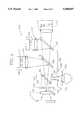
- FIG. 1there is illustrated a prior art optical projection system 100 comprising non-point white light source 1, a Schlieren bar 2 provided with a plurality of reflective surfaces and corresponding number of slits, a source lens 3, a projection lens 4, a field lens system 5, a projection screen 6, a beam splitting means 7 including a first and a second dichroic mirrors 8, 9, and a first, a second and a third arrays 10, 11, 12 of M ⁇ N actuated mirrors 13.
- the white light reflected from each of the reflective surfacesdiverges along a second optical path and collimated by the field lens system 5, thereby being uniformly illuminated onto the beam splitting means 7 including the first and second dichroic mirrors 8,9, wherein the first dichroic mirror 8 is disposed between the field lens system 5 and the second dichroic mirror 9 facing the first array 10 of M ⁇ N actuated mirrors 13, and the second dichroic mirror 9, between the first dichroic mirror 8 and the third array 10 of M ⁇ N actuated mirrors 13 facing the second array 11 of M ⁇ N actuated mirrors 13.
- the first dichroic mirror 8receives the white light from the field lens system 5, reflects the first primary light beam of the white light to the first array 10 of M ⁇ N actuated mirrors 13, and transmits the second and third primary light beams to the second dichroic mirror 9, which, in turn, receives the second and third primary light beams from the first dichroic mirror 8, reflects the second primary light beam to the second array 11 of M ⁇ N actuated mirrors 13, and transmits the third primary light beam to the third array 12 of M ⁇ N actuated mirrors 13.
- Each of the actuated mirrors 13 of the arrays 10, 11, 12corresponds to each of the pixels to be displayed.
- the optical path of the reflected primary light beams from each of the actuated mirrors 13 in each of the arrays 10, 11, 12is determined by the amount of deflection thereof.
- the reflected primary light beams from each of the undeflected actuated mirrors in each of the arrays 10, 11, 12are focused back to the Schlieren bar 2 by the field lens system 5 via the first and second dichroic mirrors 8, 9 along the second optical path and stopped by the reflective surfaces thereof, whereas the reflected primary light beams from each of the deflected actuated mirrors in each of the arrays 10, 11, 12 are focused back to the Schlieren bar 2 by the field lens system 5 via the first and second dichroic mirrors 8, 9 along a third optical path so that a portion of the focused light beams passes the slits thereof.
- the primary light beams from each of the actuated mirrors 13 in each of the arrays 10, 11, 12 which pass through the slitsare transmitted to the projection lens 4 which projects the transmitted primary light beams from each of the actuated mirrors 13 in each of the arrays 10, 11, 12 on the projection screen 6, thereby displaying each of the pixels corresponding thereto.
- the Schlieren bar 2Since the white light emanating from the non-point light source 1 is focused onto the reflective surfaces of the Schlieren bar 2 at a fixed angle, the reflected white light therefrom is extremely divergent and has a large beam diameter, and in order to uniformly illuminate such a white light onto the beam splitting means 7 and onto the arrays 10, 11, 12 of M ⁇ N actuated mirrors 13 and then refocus the reflected light from the arrays 10, 11, 12 of M ⁇ N actuated mirrors 13 to the Schlieren bar 2, the field lens system 5 employed therein must become extremely complicated.
- FIG. 1represents a schematic view of a prior art optical projection system
- FIG. 3shows a schematic view of the optical projection system incorporating therein a detailed view of the optical means shown in FIG. 2;
- FIG. 4depicts a schematic view of the optical projection system incorporating therein a detailed view of another optical means shown in FIG. 2.
- FIGS. 2 to 4there are provided schematic views of the inventive optical projection system in accordance with preferred embodiments of the present invention. It should be noted that like parts appearing in FIGS. 2 to 4 are represented by like reference numerals.
- FIG. 2there is illustrated a schematic view of the inventive optical projection system 200 comprising a non-point white light source 101, a source lens 102, a source stopper 103 provided with a light transmitting portion 51 having a specific configuration and a light stopping portion 61, an optical means 104 including a reflective surface 120, a beam splitting means 105 including a first and a second dichroic mirrors 106, 107, a trinity of arrays of M ⁇ N actuated mirrors 111 including a first, a second and a third arrays 108, 109, 110 of M ⁇ N actuated mirrors 111, a trinity of field lenses including a first, a second and a third field lenses 112, 113, 114, a projection stopper 115 provided with a light transmitting portion 52 having a specific configuration and a light stopping portion 62, a projection lens 116 and a projection screen 117.
- an optical means 104including a reflective surface 120
- a beam splitting means 105including
- a white light emanating from the non-point white light source 101is focused along a first optical path on a first optical plane onto the light transmitting portion 51 on the source stopper 103 by the source lens 102 located between the non-point white light source 101 and the source stopper 103, wherein the white light consists of a first, a second and a third primary light beams, each of the primary light beams being one of the primary colors.
- the source stopper 103is used for shaping the white light from the non-point white light source 101 via the source lens 102 into a predetermined configuration by allowing a certain portion of the white light to pass through the light transmitting portion 51 thereof.
- the white light from the source stopper 103 having the predetermined configurationtravels onto the reflective surface 120 of the optical means 104.
- the reflective surface 120 of the optical means 104inclined at an angle, e.g., 48°-50° with respect to the first optical plane, is in a facing relationship with the source stopper 103 and the beam splitting means 105.
- the white light reflected from the reflective surface 120 of the optical means 104travels along a second optical path, and is uniformly illuminated onto the beam splitting means 105 including the first and second dichroic mirrors 106,107.
- the second optical pathis inclined 80°-100° with respect to the first optical path.
- the first dichroic mirror 106inclined at an angle, e.g., 45°, and disposed between the optical means 104 and the second dichroic mirror 107 facing the first array 10 of M ⁇ N actuated mirrors 111, receives the white light from the reflective surface 120 of the optical means 104, isolates and reflects the first primary light beam of the white light to the first array 108 of M ⁇ N actuated mirrors 111, and transmits the second and third primary light beams to the second dichroic mirror 107.
- an anglee.g. 45°
- the second dichroic mirrorinclined at an angle, e.g., 45° and disposed between the third array 110 of M ⁇ N actuated mirrors 111 and the first dichroic mirror 106 facing the second array 109 of M ⁇ N actuated mirrors 111, upon receiving the second and third primary light beams from the first dichroic mirror 106, isolates and reflects the second primary light beam to the second array 109 of M ⁇ N actuated mirrors 111, and transmits the third primary light beam to the third array 110 of M ⁇ N actuated mirrors 111.
- Each of the actuated mirrors 111 in the arrays 108, 109, 110includes a mirror 53 and an actuator 54 made of a piezoelectric material or an electrostrictive material which deforms in response to an electric field applied thereto.
- Each of the actuated mirrors 111 in the arrays 108, 109, 110corresponds to each of the pixels to be displayed.
- Each of the first, second and third field lenses 112, 113, 114located between the first dichroic mirror 106 and the first array 108 of M ⁇ N actuated mirrors 111, the second dichroic mirror 107 and the second array 109 of M ⁇ N actuated mirrors 111, and the second dichroic mirror 107 and the third array 110 of M ⁇ N actuated mirrors 111, respectively, is used for collimating each of the primary light beams from each of the dichroic mirrors 106, 107 in the beam splitting means 105 to thereby uniformly illuminating each of the primary light beams onto the corresponding array of M ⁇ N actuated mirrors.
- the optical path of the reflected primary light beams from each of the actuated mirrors 111 in each of the arrays 108, 109, 110is determined by the amount of deflection thereof.
- the reflected primary light beams from each of the undeflected actuated mirrors in each of the arrays 108, 109, 110are focused back to projection stopper 115 by the corresponding field lens via the beam splitting means 105 and stopped by the light stopping portion 62 of the projection stopper 115 disposed between the projection lens 116 and the optical means 104, whereas the reflected primary light beams from each of the deflected actuated mirrors in each of the arrays 108, 109, 110 are focused back to projection stopper 115 by the corresponding field lens via the beam splitting means 105, along a third optical path so that a portion of the focused primary light beams passes through the light transmitting portion 52 of the projection stopper 115 to thereby modulating the intensity of the primary light beams.
- the optical path for each of the primary light beams between the optical means 104 and each of the arrays 108, 109, 110 of the actuated mirrors 111must be of a same length. Furthermore, the optical path each of the primary light beams travels from the source stopper 103 to each of the arrays 108, 109, 110 of M ⁇ N actuated mirrors 111 and from each of the arrays 108, 109, 110 of M ⁇ N actuated mirrors 111 to the projection stopper 115 must be of a same length.
- the source and projection stoppers 103, 115are placed at the focal point of the field lenses 112, 113, 114 employed therein.
- the light density of the optical projection system 200is at its highest when all of the white light that passed through the light transmitting portion 51 of the source stopper 103 passes through the light transmitting portion 61 of the projection stopper 115, and this can be accomplished by making the light transmitting portions 51, 61 of the source and projection stoppers 103, 115 identical in shape and size.
- the primary light beams from each of the actuated mirrors 111 in the arrays 108, 109, 110 which pass through the light transmitting portion 61 of the projection stopper 115 located at the focal point of the field lenses 112, 113, 114are transmitted to the projection lens 116 which, in turn, projects the transmitted primary light beams onto the projection screen 117, thereby displaying each of the pixels to be displayed.
- the inventive optical projection system 200employs the trinity of field lenses 112, 113, 114, each of the field lenses being located between the first dichroic mirror 106 and the first array 108 of actuated mirrors 111, the second dichroic mirror 107 and the second array 109 of actuated mirrors 111, and the second dichroic mirror 107 and the third array 110 of actuated mirrors 111, respectively.
- each of the primary light beamsbecomes less divergent and has a smaller beam diameter, and therefore, can be easily focused, thereby eliminating a need employ a complicated field lens system.
- FIG. 3a schematic diagram of the inventive optical projection system 200 incorporating therein an optical means 104 having a total mirror 54 capable of a total reflection of the white light from the source stopper 103 onto the beam splitting means 105.
- FIG. 4a schematic diagram of the inventive optical projection system 200 incorporating a polarization beam spitter (PBS) 55 and a ⁇ /4 plate 56, wherein the PBS 55 is used for separating the white light into a pair of polarization beams, a first and a second polarization beams, and reflecting one of the polarization beams to the ⁇ /4 plate 56, and the ⁇ /4 plate 56, upon receiving the reflected polarization beam from the PBS 55, is used for changing the phase of the reflected polarization beam from the PBS 55 and transmitting the phase changed polarization beam to the beam splitting means 105.
- PBSpolarization beam spitter
Landscapes
- Engineering & Computer Science (AREA)
- Multimedia (AREA)
- Signal Processing (AREA)
- Projection Apparatus (AREA)
- Mechanical Light Control Or Optical Switches (AREA)
- Microscoopes, Condenser (AREA)
- Non-Portable Lighting Devices Or Systems Thereof (AREA)
- Devices For Indicating Variable Information By Combining Individual Elements (AREA)
- Video Image Reproduction Devices For Color Tv Systems (AREA)
- Lenses (AREA)
Abstract
Description
Claims (11)
Applications Claiming Priority (4)
| Application Number | Priority Date | Filing Date | Title |
|---|---|---|---|
| KR94-4518 | 1994-03-09 | ||
| KR19940004517 | 1994-03-09 | ||
| KR94-4517 | 1994-03-09 | ||
| KR1019940004518AKR950027447A (en) | 1994-03-09 | 1994-03-09 | Projection Image Display Device Using Polarization Separator |
Publications (1)
| Publication Number | Publication Date |
|---|---|
| US5560697Atrue US5560697A (en) | 1996-10-01 |
Family
ID=26630238
Family Applications (1)
| Application Number | Title | Priority Date | Filing Date |
|---|---|---|---|
| US08/400,727Expired - LifetimeUS5560697A (en) | 1994-03-09 | 1995-03-08 | Optical projection system |
Country Status (20)
| Country | Link |
|---|---|
| US (1) | US5560697A (en) |
| EP (1) | EP0671854B1 (en) |
| JP (1) | JPH09510026A (en) |
| CN (1) | CN1070331C (en) |
| AU (1) | AU683542B2 (en) |
| BR (1) | BR9507021A (en) |
| CA (1) | CA2191131A1 (en) |
| CZ (1) | CZ263796A3 (en) |
| DE (1) | DE69517220T2 (en) |
| ES (1) | ES2146674T3 (en) |
| HU (1) | HU220537B1 (en) |
| MX (1) | MX9603948A (en) |
| MY (1) | MY111997A (en) |
| PE (1) | PE20196A1 (en) |
| PH (1) | PH31489A (en) |
| PL (1) | PL176882B1 (en) |
| RU (1) | RU2154352C2 (en) |
| TW (1) | TW260752B (en) |
| UY (1) | UY23932A1 (en) |
| WO (1) | WO1995024799A1 (en) |
Cited By (12)
| Publication number | Priority date | Publication date | Assignee | Title |
|---|---|---|---|---|
| US5669687A (en)* | 1994-10-31 | 1997-09-23 | Daewoo Electronics Co., Ltd. | Optical projection system |
| US5826553A (en)* | 1995-02-01 | 1998-10-27 | Nippondenso Co., Ltd. | Air intake device for an internal combustion engine |
| US5845981A (en)* | 1997-12-29 | 1998-12-08 | Philips Electronics North America Corporation | Multi-color-band scrolling across single-panel light valve |
| US5895109A (en)* | 1995-10-12 | 1999-04-20 | Sony Corporation | Projector |
| US6052229A (en)* | 1998-12-24 | 2000-04-18 | Daewoo Electronics Co., Ltd. | Image display system using a thin-film actuated mirror array |
| US6094294A (en)* | 1996-02-26 | 2000-07-25 | Seiko Epson Corporation | Optical modulator device, display and electronic apparatus |
| US6276801B1 (en)* | 1994-08-04 | 2001-08-21 | Digital Projection Limited | Display system |
| US6491398B2 (en)* | 1999-01-08 | 2002-12-10 | Nec Viewtechnology, Ltd. | Video projector |
| US20030048390A1 (en)* | 2001-08-17 | 2003-03-13 | Cae Inc. | Video projector and optical light valve therefor |
| US6666558B1 (en)* | 1999-07-02 | 2003-12-23 | Matsushita Electric Industrial Co., Ltd. | Projection image display |
| CN109141835A (en)* | 2018-09-28 | 2019-01-04 | 中国兵器工业标准化研究所 | Projection and the two-in-one optic testing system of schlieren |
| US20240027342A1 (en)* | 2021-10-20 | 2024-01-25 | United States Of America As Represented By The Administrator Of Nasa | Real-time, reference-free background oriented schlieren imaging system |
Families Citing this family (10)
| Publication number | Priority date | Publication date | Assignee | Title |
|---|---|---|---|---|
| US6394606B1 (en)* | 1998-09-29 | 2002-05-28 | Sony Corporation | Projection-type display device |
| US6234634B1 (en)* | 1999-07-28 | 2001-05-22 | Moxtek | Image projection system with a polarizing beam splitter |
| CA2593124A1 (en)* | 2005-01-04 | 2006-07-13 | Hentze-Lissotschenko Patentverwaltungs Gmbh & Co. Kg. | Beam splitter arrangement |
| TWI321661B (en) | 2006-07-27 | 2010-03-11 | Young Optics Inc | Projection apparatus |
| CN101725900B (en)* | 2008-10-20 | 2011-09-28 | 鸿富锦精密工业(深圳)有限公司 | Light source device and protector using the same |
| DE102011001785B4 (en)* | 2011-04-04 | 2015-03-05 | Jenoptik Optical Systems Gmbh | Exposure device for the structured exposure of a surface |
| CN104536245A (en)* | 2014-11-11 | 2015-04-22 | 深圳市亿思达科技集团有限公司 | A Fiber Bragg Grating(FGB) based laser projector light source system |
| CN113391506B (en) | 2020-03-12 | 2022-12-06 | 中强光电股份有限公司 | Illumination system and projection device |
| US12332559B2 (en) | 2020-03-12 | 2025-06-17 | Coretronic Corporation | Illumination system and projection apparatus |
| CN113391507B (en)* | 2020-03-13 | 2022-07-19 | 中强光电股份有限公司 | Light source module and projection device |
Citations (12)
| Publication number | Priority date | Publication date | Assignee | Title |
|---|---|---|---|---|
| EP0139991A2 (en)* | 1983-09-08 | 1985-05-08 | Texas Instruments Incorporated | Optical system for projection display using spatial light modulator (1111111) |
| WO1991009503A1 (en)* | 1989-12-11 | 1991-06-27 | Aura Systems, Inc. | Television display system for modulating projected beams' intensity |
| US5170250A (en)* | 1991-02-06 | 1992-12-08 | Hughes Aircraft Company | Full-color light valve projection apparatus having internal image registration system |
| JPH0553224A (en)* | 1991-08-27 | 1993-03-05 | Pioneer Electron Corp | Color liquid crystal display device |
| US5235444A (en)* | 1988-08-26 | 1993-08-10 | U.S. Philips Corporation | Image projection arrangement |
| US5245369A (en)* | 1989-11-01 | 1993-09-14 | Aura Systems, Inc. | Scene projector |
| WO1993019620A1 (en)* | 1992-04-03 | 1993-10-14 | North Carolina State University | Method and apparatus for pasteurizing liquid whole egg products |
| US5260798A (en)* | 1989-11-01 | 1993-11-09 | Aura Systems, Inc. | Pixel intensity modulator |
| US5369433A (en)* | 1991-04-05 | 1994-11-29 | Rank Cintel Limited | Recording video signals on cinematographic film using a deformable mirror device |
| US5402184A (en)* | 1993-03-02 | 1995-03-28 | North American Philips Corporation | Projection system having image oscillation |
| US5420655A (en)* | 1992-12-16 | 1995-05-30 | North American Philips Corporation | Color projection system employing reflective display devices and prism illuminators |
| US5486881A (en)* | 1994-03-09 | 1996-01-23 | Daewoo Electronics Co., Ltd. | Unique optical projection system |
Family Cites Families (8)
| Publication number | Priority date | Publication date | Assignee | Title |
|---|---|---|---|---|
| SU1223405A1 (en)* | 1983-12-27 | 1986-04-07 | Всесоюзный Научно-Исследовательский Кинофотоинститут | Television light-valve projector |
| NL8502226A (en)* | 1985-08-12 | 1987-03-02 | Philips Nv | PROJECTION TELEVISION EQUIPMENT. |
| US5150205A (en)* | 1989-11-01 | 1992-09-22 | Aura Systems, Inc. | Actuated mirror optical intensity modulation |
| JP2681304B2 (en)* | 1990-05-16 | 1997-11-26 | 日本ビクター株式会社 | Display device |
| RU2027316C1 (en)* | 1990-06-29 | 1995-01-20 | Святослав Иванович АРСЕНИЧ | Projector of images from diffusion-emitting or radiating master patterns to external screen |
| US5268775A (en)* | 1991-02-19 | 1993-12-07 | Hughes-Jvc Technology Corporation | Contrast enhancement and ghost elimination, for reflective light valve system |
| KR930005545B1 (en)* | 1991-04-16 | 1993-06-23 | 주식회사 금성사 | Projection optics for polymer dispersed liquid crystal image module |
| GB9204798D0 (en)* | 1992-03-05 | 1992-04-15 | Rank Brimar Ltd | Spatial light modulator system |
- 1995
- 1995-03-08PEPE1995263686Apatent/PE20196A1/ennot_activeApplication Discontinuation
- 1995-03-08DEDE69517220Tpatent/DE69517220T2/ennot_activeExpired - Fee Related
- 1995-03-08TWTW084102213Apatent/TW260752B/zhactive
- 1995-03-08ESES95103345Tpatent/ES2146674T3/ennot_activeExpired - Lifetime
- 1995-03-08USUS08/400,727patent/US5560697A/ennot_activeExpired - Lifetime
- 1995-03-08EPEP95103345Apatent/EP0671854B1/ennot_activeExpired - Lifetime
- 1995-03-09CNCN95192038Apatent/CN1070331C/ennot_activeExpired - Fee Related
- 1995-03-09HUHU9602461Apatent/HU220537B1/ennot_activeIP Right Cessation
- 1995-03-09PHPH50098Apatent/PH31489A/enunknown
- 1995-03-09CZCZ962637Apatent/CZ263796A3/enunknown
- 1995-03-09AUAU19614/95Apatent/AU683542B2/ennot_activeCeased
- 1995-03-09WOPCT/KR1995/000017patent/WO1995024799A1/ennot_activeApplication Discontinuation
- 1995-03-09UYUY23932Apatent/UY23932A1/ennot_activeIP Right Cessation
- 1995-03-09MYMYPI95000583Apatent/MY111997A/enunknown
- 1995-03-09MXMX9603948Apatent/MX9603948A/enunknown
- 1995-03-09JPJP7523369Apatent/JPH09510026A/ennot_activeCeased
- 1995-03-09BRBR9507021Apatent/BR9507021A/ennot_activeApplication Discontinuation
- 1995-03-09RURU96120149/09Apatent/RU2154352C2/ennot_activeIP Right Cessation
- 1995-03-09PLPL95316171Apatent/PL176882B1/ennot_activeIP Right Cessation
- 1995-03-09CACA002191131Apatent/CA2191131A1/ennot_activeAbandoned
Patent Citations (12)
| Publication number | Priority date | Publication date | Assignee | Title |
|---|---|---|---|---|
| EP0139991A2 (en)* | 1983-09-08 | 1985-05-08 | Texas Instruments Incorporated | Optical system for projection display using spatial light modulator (1111111) |
| US5235444A (en)* | 1988-08-26 | 1993-08-10 | U.S. Philips Corporation | Image projection arrangement |
| US5245369A (en)* | 1989-11-01 | 1993-09-14 | Aura Systems, Inc. | Scene projector |
| US5260798A (en)* | 1989-11-01 | 1993-11-09 | Aura Systems, Inc. | Pixel intensity modulator |
| WO1991009503A1 (en)* | 1989-12-11 | 1991-06-27 | Aura Systems, Inc. | Television display system for modulating projected beams' intensity |
| US5170250A (en)* | 1991-02-06 | 1992-12-08 | Hughes Aircraft Company | Full-color light valve projection apparatus having internal image registration system |
| US5369433A (en)* | 1991-04-05 | 1994-11-29 | Rank Cintel Limited | Recording video signals on cinematographic film using a deformable mirror device |
| JPH0553224A (en)* | 1991-08-27 | 1993-03-05 | Pioneer Electron Corp | Color liquid crystal display device |
| WO1993019620A1 (en)* | 1992-04-03 | 1993-10-14 | North Carolina State University | Method and apparatus for pasteurizing liquid whole egg products |
| US5420655A (en)* | 1992-12-16 | 1995-05-30 | North American Philips Corporation | Color projection system employing reflective display devices and prism illuminators |
| US5402184A (en)* | 1993-03-02 | 1995-03-28 | North American Philips Corporation | Projection system having image oscillation |
| US5486881A (en)* | 1994-03-09 | 1996-01-23 | Daewoo Electronics Co., Ltd. | Unique optical projection system |
Cited By (16)
| Publication number | Priority date | Publication date | Assignee | Title |
|---|---|---|---|---|
| US6276801B1 (en)* | 1994-08-04 | 2001-08-21 | Digital Projection Limited | Display system |
| US6631993B2 (en) | 1994-08-04 | 2003-10-14 | Texas Instruments Incorporated | Display system |
| US5669687A (en)* | 1994-10-31 | 1997-09-23 | Daewoo Electronics Co., Ltd. | Optical projection system |
| US5826553A (en)* | 1995-02-01 | 1998-10-27 | Nippondenso Co., Ltd. | Air intake device for an internal combustion engine |
| US5895109A (en)* | 1995-10-12 | 1999-04-20 | Sony Corporation | Projector |
| US6094294A (en)* | 1996-02-26 | 2000-07-25 | Seiko Epson Corporation | Optical modulator device, display and electronic apparatus |
| US5845981A (en)* | 1997-12-29 | 1998-12-08 | Philips Electronics North America Corporation | Multi-color-band scrolling across single-panel light valve |
| US6052229A (en)* | 1998-12-24 | 2000-04-18 | Daewoo Electronics Co., Ltd. | Image display system using a thin-film actuated mirror array |
| US6491398B2 (en)* | 1999-01-08 | 2002-12-10 | Nec Viewtechnology, Ltd. | Video projector |
| US6666558B1 (en)* | 1999-07-02 | 2003-12-23 | Matsushita Electric Industrial Co., Ltd. | Projection image display |
| US20030048390A1 (en)* | 2001-08-17 | 2003-03-13 | Cae Inc. | Video projector and optical light valve therefor |
| US7116380B2 (en)* | 2001-08-17 | 2006-10-03 | Cae Inc. | Video projector and optical light valve therefor |
| CN109141835A (en)* | 2018-09-28 | 2019-01-04 | 中国兵器工业标准化研究所 | Projection and the two-in-one optic testing system of schlieren |
| CN109141835B (en)* | 2018-09-28 | 2019-12-24 | 中国兵器工业标准化研究所 | Projection and schlieren two-in-one optical test system |
| US10962488B2 (en) | 2018-09-28 | 2021-03-30 | China North Standardization Center | Integrated projection-schlieren optical system |
| US20240027342A1 (en)* | 2021-10-20 | 2024-01-25 | United States Of America As Represented By The Administrator Of Nasa | Real-time, reference-free background oriented schlieren imaging system |
Also Published As
| Publication number | Publication date |
|---|---|
| AU683542B2 (en) | 1997-11-13 |
| HU9602461D0 (en) | 1996-11-28 |
| CA2191131A1 (en) | 1995-09-14 |
| AU1961495A (en) | 1995-09-25 |
| DE69517220T2 (en) | 2000-10-12 |
| PL176882B1 (en) | 1999-08-31 |
| RU2154352C2 (en) | 2000-08-10 |
| HU220537B1 (en) | 2002-03-28 |
| CN1070331C (en) | 2001-08-29 |
| MY111997A (en) | 2001-03-31 |
| JPH09510026A (en) | 1997-10-07 |
| TW260752B (en) | 1995-10-21 |
| BR9507021A (en) | 1997-09-09 |
| PL316171A1 (en) | 1996-12-23 |
| WO1995024799A1 (en) | 1995-09-14 |
| PE20196A1 (en) | 1996-08-11 |
| MX9603948A (en) | 1997-06-28 |
| ES2146674T3 (en) | 2000-08-16 |
| CN1144027A (en) | 1997-02-26 |
| DE69517220D1 (en) | 2000-07-06 |
| UY23932A1 (en) | 1995-05-14 |
| CZ263796A3 (en) | 1998-01-14 |
| EP0671854B1 (en) | 2000-05-31 |
| EP0671854A1 (en) | 1995-09-13 |
| HUT76500A (en) | 1997-09-29 |
| PH31489A (en) | 1998-11-03 |
Similar Documents
| Publication | Publication Date | Title |
|---|---|---|
| US5560697A (en) | Optical projection system | |
| US5486881A (en) | Unique optical projection system | |
| US5541679A (en) | Optical projection system | |
| CA2096120C (en) | Scene projector | |
| US5450219A (en) | Raster following telecentric illumination scanning system for enhancing light throughout in light valve projection systems | |
| US6796655B2 (en) | Projection-type display apparatus | |
| MXPA96003948A (en) | Opt projection system | |
| US20030234751A1 (en) | Image display apparatus having optical scanner | |
| US5640479A (en) | Fiberoptic face plate stop for digital micromirror device projection system | |
| US5504629A (en) | Optical projection system with a novel lens system | |
| US5564811A (en) | Optical projection system with a varifocal projection lens | |
| US5299036A (en) | Liquid crystal projector including a polaration rotating element | |
| US5612814A (en) | Compact sized optical projection system | |
| IL96200A (en) | Television display apparatus | |
| JP2001516472A (en) | Multi-color band scroll with single panel light valve | |
| KR960030675A (en) | Multiple color light projection device | |
| RU96120149A (en) | OPTICAL PROJECTION SYSTEM | |
| US5319490A (en) | Helmet mounted display including synchronously moving tilted mechanisms | |
| EP1052856A3 (en) | Reflection type color projector | |
| US6822773B2 (en) | Scanning type image display optical system, scanning type image display apparatus, and image display system | |
| KR100397427B1 (en) | Polarizing Light Converting Apparatus | |
| US5777781A (en) | Optical projection system | |
| KR0184364B1 (en) | 3d image projector using optical reflective modulator | |
| US5249006A (en) | High power magnifying projector | |
| JP2001100310A (en) | Lens unit for liquid crystal projector |
Legal Events
| Date | Code | Title | Description |
|---|---|---|---|
| AS | Assignment | Owner name:DAEWOO ELECTRONICS CO., LTD., KOREA, REPUBLIC OF Free format text:ASSIGNMENT OF ASSIGNORS INTEREST;ASSIGNORS:LIM, DAE-YOUNG;YANG, JIN-SE;REEL/FRAME:007393/0666 Effective date:19950303 | |
| STCF | Information on status: patent grant | Free format text:PATENTED CASE | |
| FEPP | Fee payment procedure | Free format text:PAYOR NUMBER ASSIGNED (ORIGINAL EVENT CODE: ASPN); ENTITY STATUS OF PATENT OWNER: LARGE ENTITY | |
| FPAY | Fee payment | Year of fee payment:4 | |
| AS | Assignment | Owner name:DAEWOO ELECTRONICS CORPORATION, KOREA, REPUBLIC OF Free format text:ASSIGNMENT OF ASSIGNORS INTEREST;ASSIGNOR:DAEWOO ELECTRONICS CO., LTD.;REEL/FRAME:014363/0688 Effective date:20030517 | |
| FPAY | Fee payment | Year of fee payment:8 | |
| FPAY | Fee payment | Year of fee payment:12 | |
| AS | Assignment | Owner name:MAPLE VISION TECHNOLOGIES INC., CANADA Free format text:ASSIGNMENT OF ASSIGNORS INTEREST;ASSIGNOR:DAEWOO ELECTRONICS CORPORATION;REEL/FRAME:027437/0446 Effective date:20111215 | |
| AS | Assignment | Owner name:QUARTERHILL INC., CANADA Free format text:MERGER AND CHANGE OF NAME;ASSIGNORS:MAPLE VISION TECHNOLOGIES INC.;QUARTERHILL INC.;REEL/FRAME:042936/0464 Effective date:20170601 | |
| AS | Assignment | Owner name:WI-LAN INC., CANADA Free format text:ASSIGNMENT OF ASSIGNORS INTEREST;ASSIGNOR:QUARTERHILL INC.;REEL/FRAME:043181/0001 Effective date:20170601 |