US5560376A - Method of and apparatus for adjusting the moisture content of a fuel component for a smoking article - Google Patents
Method of and apparatus for adjusting the moisture content of a fuel component for a smoking articleDownload PDFInfo
- Publication number
- US5560376A US5560376AUS08/369,018US36901895AUS5560376AUS 5560376 AUS5560376 AUS 5560376AUS 36901895 AUS36901895 AUS 36901895AUS 5560376 AUS5560376 AUS 5560376A
- Authority
- US
- United States
- Prior art keywords
- fuel
- air
- moisture content
- fuel components
- dryer
- Prior art date
- Legal status (The legal status is an assumption and is not a legal conclusion. Google has not performed a legal analysis and makes no representation as to the accuracy of the status listed.)
- Expired - Lifetime
Links
- 239000000446fuelSubstances0.000titleclaimsabstractdescription215
- 238000000034methodMethods0.000titleclaimsabstractdescription28
- 230000000391smoking effectEffects0.000titleclaimsabstractdescription17
- 238000005520cutting processMethods0.000claimsabstractdescription15
- 238000004519manufacturing processMethods0.000claimsabstractdescription9
- 239000003570airSubstances0.000claimsdescription115
- 239000012080ambient airSubstances0.000claimsdescription26
- 238000011144upstream manufacturingMethods0.000claimsdescription10
- 238000010438heat treatmentMethods0.000claimsdescription8
- 238000007599dischargingMethods0.000claims1
- 239000000758substrateSubstances0.000abstractdescription47
- 239000000443aerosolSubstances0.000abstractdescription5
- 238000005336crackingMethods0.000abstract1
- 239000000047productSubstances0.000description48
- 238000001035dryingMethods0.000description28
- 235000019504cigarettesNutrition0.000description12
- 238000010276constructionMethods0.000description5
- 239000000945fillerSubstances0.000description5
- 239000000463materialSubstances0.000description5
- 230000008569processEffects0.000description5
- 238000007602hot air dryingMethods0.000description4
- 230000008961swellingEffects0.000description4
- 101100129500Caenorhabditis elegans max-2 geneProteins0.000description3
- 239000003365glass fiberSubstances0.000description3
- 239000000853adhesiveSubstances0.000description2
- 230000001070adhesive effectEffects0.000description2
- 230000002411adverseEffects0.000description2
- 239000012467final productSubstances0.000description2
- 230000005012migrationEffects0.000description2
- 238000013508migrationMethods0.000description2
- 238000004806packaging method and processMethods0.000description2
- 238000009827uniform distributionMethods0.000description2
- XLYOFNOQVPJJNP-UHFFFAOYSA-NwaterChemical compoundOXLYOFNOQVPJJNP-UHFFFAOYSA-N0.000description2
- 238000009825accumulationMethods0.000description1
- 238000007664blowingMethods0.000description1
- 239000003795chemical substances by applicationSubstances0.000description1
- 238000002845discolorationMethods0.000description1
- 238000011143downstream manufacturingMethods0.000description1
- 238000001125extrusionMethods0.000description1
- 238000011065in-situ storageMethods0.000description1
- 239000000203mixtureSubstances0.000description1
- 238000012986modificationMethods0.000description1
- 230000004048modificationEffects0.000description1
Images


Classifications
- A—HUMAN NECESSITIES
- A24—TOBACCO; CIGARS; CIGARETTES; SIMULATED SMOKING DEVICES; SMOKERS' REQUISITES
- A24C—MACHINES FOR MAKING CIGARS OR CIGARETTES
- A24C5/00—Making cigarettes; Making tipping materials for, or attaching filters or mouthpieces to, cigars or cigarettes
- A24C5/60—Final treatment of cigarettes, e.g. marking, printing, branding, decorating
- A24C5/603—Final drying of cigarettes
- A—HUMAN NECESSITIES
- A24—TOBACCO; CIGARS; CIGARETTES; SIMULATED SMOKING DEVICES; SMOKERS' REQUISITES
- A24B—MANUFACTURE OR PREPARATION OF TOBACCO FOR SMOKING OR CHEWING; TOBACCO; SNUFF
- A24B3/00—Preparing tobacco in the factory
- A24B3/04—Humidifying or drying tobacco bunches or cut tobacco
- A—HUMAN NECESSITIES
- A24—TOBACCO; CIGARS; CIGARETTES; SIMULATED SMOKING DEVICES; SMOKERS' REQUISITES
- A24C—MACHINES FOR MAKING CIGARS OR CIGARETTES
- A24C5/00—Making cigarettes; Making tipping materials for, or attaching filters or mouthpieces to, cigars or cigarettes
- A—HUMAN NECESSITIES
- A24—TOBACCO; CIGARS; CIGARETTES; SIMULATED SMOKING DEVICES; SMOKERS' REQUISITES
- A24D—CIGARS; CIGARETTES; TOBACCO SMOKE FILTERS; MOUTHPIECES FOR CIGARS OR CIGARETTES; MANUFACTURE OF TOBACCO SMOKE FILTERS OR MOUTHPIECES
- A24D1/00—Cigars; Cigarettes
- A24D1/22—Cigarettes with integrated combustible heat sources, e.g. with carbonaceous heat sources
Definitions
- the present inventionrelates to drying apparatus and methods and more particularly to a method of and an apparatus for adjusting and controlling the moisture content of a carbonaceous fuel element used in the manufacture of smoking articles, such as cigarettes.
- Recent improvements in smoking articlesinclude cigarettes of a type having a fuel component, a physically separate aerosol generator or substrate and a separate mouthpiece component. See, e.g., U.S. Pat. No. 4,714,082 assigned to the assignee of this invention. Apparatus and processes for mass producing such improved cigarette smoking articles are disclosed, for example, in U.S. patent application Ser. No. 089,502 filed Jul. 16, 1993 and U.S. patent application Ser. No. 856,239 filed Mar. 25, 1992, both assigned to the assignee of the present invention and the disclosures of which are incorporated herein by reference.
- the fuel componentincludes an extruded carbonaceous fuel element which is circumscribed by a resilient insulating jacket, such as a mat or layer of glass fibers, and is then overwrapped with a cigarette paper or paper-like material and glued, e.g., with a cold adhesive seal, along a longitudinal seam, to form a continuous cylindrical fuel rod.
- the continuous overwrapped fuel rodmay then be cut into shorter lengths to form fuel components suitable for processing, e.g., a six-up fuel rod having a length of about 72 mm.
- drying of the fuel elementmay be accomplished after the extruded fuel rod is overwrapped and cut into predetermined lengths or at other stages of the cigarette manufacturing process.
- drying apparatusincluding passive dryers such as a timed accumulator system, e.g., a Resy accumulator available from Korber & Co., AG, of Hamburg, Germany (hereinafter "Korber") or an S-90 accumulator available from G. D. Societe per Anzioni of Bologna, Italy (hereinafter "GD”) or active dryers, such as a hot air blowing system.
- the drying stagesmay be eliminated and relocated since the moisture content of the extruded fuel rod depends on the initial moisture content of the rod and the time lapse between the different stages in the manufacturing process.
- drying of the extrudate fuel rod to a relatively low moisture content to prevent the aforesaid problems that occur with a high moisture contentcan also cause problems with processing of the fuel component. For instance, if the overwrapped six-up fuel component has too low a moisture content, i.e., is too dry, the extruded rod tends to fracture or chip when the six-up fuel component is cut into individual fuel elements for assembly into cigarette smoking articles.
- the present inventionis directed to a method of and an apparatus for controllably adjusting the moisture content of a fuel component for smoking articles comprising an extruded carbonaceous fuel rod circumscribed with a resilient jacket, overwrapped with paper or a paper-like material and sealed along a longitudinal seam to form a continuous fuel rod which is then cut into individual fuel components.
- the extruded carbonaceous fuel rodadvantageously has a relatively high moisture content for optimum extrusion characteristics.
- the moisture content of the extruded carbonaceous rodis in the range of 30% to 40% by weight.
- the overall moisture content of the extruded fuel rodmay be, for example, in the range of about 30% to 36%.
- the moisture content of the overwrap papermust be maintained relatively low, preferably in the range of about 6% to about 18%, and most preferably at the lower end of that range, e.g., about 8% to 12%. Should moisture content of the overwrap paper exceed about 18%, the overwrapped fuel component will swell circumferentially to a degree that may cause subsequent transporting and processing problems. Accordingly, the moisture content of the overwrap paper must be maintained relatively low during the entire time it is overwrapped about the high moisture content extruded fuel rod. On the other hand, the moisture content of the extruded fuel rod must be maintained above a certain minimum value for reasons that will be explained hereafter.
- the fuel componentsare accumulated in a mass flow accumulation system, such as a conventional Resy accumulator modified according to the present invention to maintain the moisture content of the overwrap paper in the approximate range of 6% to 18% to prevent the paper from swelling, splitting or discoloring.
- a mass flow accumulation systemsuch as a conventional Resy accumulator modified according to the present invention to maintain the moisture content of the overwrap paper in the approximate range of 6% to 18% to prevent the paper from swelling, splitting or discoloring.
- Thisis accomplished in the accumulator by drawing unheated ambient air over the six-up fuel components at a rate sufficient to remove enough moisture to maintain the moisture content of the paper below 18%, but not sufficient to reduce the moisture content of the extruded carbonaceous rod below about 20%.
- the moisture content of the extruded rodis maintained at a moisture content of about 22% to 30%. Under some conditions or with different fuel component configurations, it may be desirable or necessary to heat the ambient air to maintain the appropriate moisture content.
- the overwrapped six-up fuel componentcan usually be successfully cut without fracturing or chipping the extruded rod if the moisture content of the rod is above about 18%.
- the preferred range of moisture content of the extruded rod for cutting the six-up fuel componentsin the 22% to 30% range.
- the higher the moisture content in that rangethe more easily the fuel component can be cut without fracturing or chipping the extruded rod.
- the composition of the carbonaceous fuel rodmay vary substantially, so also will the range of moisture content of the extruded rod that is most advantageous or optimum for accumulating and processing the fuel components and for cutting the fuel components into individual fuel elements suitable for attachment to a separate aerosol generator or substrate.
- the accumulatorsupplies the six-up (72 mm long) fuel components to a tipping apparatus, such as a Max R-1 or Max 2 tipper available from Korber, where each component is cut into six lengths of about 12 mm each to form six jacketed fuel elements, which are then combined with substrates on a drum in the tipper to form two-up fuel element/substrate sections approximately 86 mm in length.
- a tipping apparatussuch as a Max R-1 or Max 2 tipper available from Korber
- each componentis cut into six lengths of about 12 mm each to form six jacketed fuel elements, which are then combined with substrates on a drum in the tipper to form two-up fuel element/substrate sections approximately 86 mm in length.
- Each fuel element/substrate sectioncomprises, e.g., two 12 mm fuel elements affixed to the opposite ends of a 62 mm two-up substrate.
- the moisture content of the extruded rod when it is cut in the tipperis preferably in the range of about 22% to 30% to prevent chipping and fracturing of the rod and is preferably toward the high end of that range, e.g., 25% to 30%, while the moisture content of the overwrap paper is maintained in the 6% to 18% range.
- the resultant fuel element/substrate sectionsare then transferred to a dryer apparatus where they are contacted with heated ambient air to remove additional moisture from the extruded fuel rod and reduce the difference in the moisture content between the overwrap paper and the extruded rod.
- the temperature of the heated ambient air supplied to the dryer apparatusis preferably in the range of 110° F. to 120° F., but may be as high as 150° F. to 160° F. without adversely affecting the handling and transporting characteristics of the fuel element/substrate sections.
- the dryer apparatusmay also be a conventional Resy accumulator modified according to the present invention to introduce heated ambient air across the flow path of the fuel element/substrate sections as they pass through the apparatus from inlet to outlet. Temperature and flow rate of the heated air may be adjusted to achieve the desired final moisture content of the fuel element/substrate sections and to reduce the moisture content difference between the fuel elements and the substrate sections.
- the two-up fuel element/substrate sectionsmay be transferred to an HCF tray filler, or to a mass flow conveyor for further assembly into smoking articles as described more fully in the aforementioned U.S. patent application Ser. No. 089,502.
- the method and apparatus of the present inventionare capable of advantageously maintaining and adjusting the moisture content of the two primary parts of the fuel component, namely, the extruded fuel rod and the overwrap paper, to appropriate levels to optimize the conditions for processing and transporting the fuel component and the combined fuel component/substrate sections.
- Two embodiments of the apparatus of the inventionare disclosed, namely, a first embodiment in which four blowers or fans and two air heaters are used to supply and exhaust heated air to and from the dryer apparatus, and a second embodiment of less complex construction in which only two blowers or fans and one air heater are used to supply and exhaust heated air to and from the dryer apparatus.
- the second embodimentalso utilizes a more simplified system for drawing unheated air over the overwrapped fuel component in the mass flow accumulator section of the apparatus.
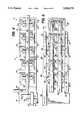
- FIG. 1is a perspective view of a first embodiment of the entire apparatus of the invention
- FIG. 2is a front elevation view, partly in cross-section, of the mass flow accumulator section of the first embodiment of the apparatus of the invention
- FIG. 3is a detail of the input conveyor of the mass flow accumulator section shown in FIG. 2;
- FIG. 4is a rear elevation view showing the exhaust ducts for the mass flow section
- FIG. 5is a front elevation view, partly in cross-section, of the dryer section of the apparatus of the invention.
- FIG. 6is a rear elevation view showing the heated air and exhaust ducts for the dryer section
- FIG. 7is a cross-sectional view of the mass flow section taken along line 7--7 of FIG. 2;
- FIGS. 8-10are cross-sectional views of the dryer section taken along lines 8--8, 9--9 and 10--10 of FIG. 3;
- FIG. 11is a cross-sectional view showing plenum details of the dryer section
- FIG. 12is a perspective view of a second embodiment of the apparatus of the invention.
- FIG. 13is a fragmentary cross-sectional elevation view of the inlet portion of the mass flow accumulator section of the FIG. 12 second embodiment of the invention.
- FIG. 14is a rear elevation view showing the air exhaust ducts for the mass flow accumulator section of the FIG. 12 second embodiment
- FIG. 15is a fragmentary cross-sectional elevation view of the inlet portion of the dryer section of the FIG. 12 second embodiment
- FIG. 16is a rear elevation view showing the heated air and exhaust ducts for the dryer section of the FIG. 12 second embodiment
- FIG. 17is a cross-sectional view of the mass flow accumulator section taken along line 17--17 of FIG. 13;
- FIG. 18is a cross-sectional view of the dryer section taken along line 18--18 of FIG. 15.
- FIG. 1illustrates the first embodiment of the moisture adjusting and drying apparatus 10 of the present invention associated with other components of the equipment used to manufacture smoking articles of the type disclosed in the aforesaid U.S. patent application Ser. No. 089,502.
- the apparatus 10is constructed in two sections designated generally by reference numerals 12 and 14.
- the first or upstream sectioncomprises a moisture adjusting accumulator 12, such as a Resy mass flow accumulator modified in accordance with the present invention.
- the second or downstream section of the apparatus 10comprises a hot air drying section 14, such as another Resy mass flow accumulator also modified in accordance with the invention.
- the first section 12includes an input conveyor section 16 which is connected to an upstream apparatus (not shown) for supplying fuel components to the apparatus 10 for processing.
- the fuel componentsmay be supplied, for example, from the output of the equipment disclosed in the aforementioned U.S. patent application Ser. No. 856,239 which output comprises an extruded carbonaceous fuel rod circumscribed with a resilient glass fiber layer, then overwrapped with a layer of paper or paper-like material and sealed along a longitudinal seam. This fuel rod is then cut into six-up fuel components which are deposited on the input conveyor 16, with the longitudinal axes of the fuel components arranged transversely to the direction of travel of the conveyor 16.
- the first section 12is connected via ambient air manifold piping 18 to a pair of blowers or fans 20, 22 which draw ambient air through the first section and over the fuel components therein as more fully explained hereinbelow. In most cases, the ambient air is unheated, however, it may be desirable or necessary to heat the air.
- a tipping apparatus 24such as a Max R-1 or Max-2 tipper where they are cut into individual fuel elements which are then combined two each with a two-up aerosol generator or substrate, as described in the aforementioned U.S. patent application Ser. No. 089,502, and conveyed as two-up fuel element/substrate units to the outlet conveyor 26 of the tipper 24.
- Outlet conveyor 26also comprises the inlet conveyor for the second section or hot air dryer section 14 of the apparatus 10.
- the second section 14may be a Resy accumulator modified to form a flow path of sufficient length to provide the required residence time for drying of the fuel components.
- the second section 14is connected via hot air manifold piping 28 to two blowers or fans 30, 32 and heaters 34, 36 which supply heated ambient air to the second section 14.
- Heaters 34, 36are supplied with steam for heating purposes via steam inlet lines 35, 37 from a source (not shown). Other heating sources, e.g., electrical heaters, may be used. Drying air is heated to a temperature in the range of about 110° F. to 160° F., and preferably to about 120° F.
- Two additional blowers or fans 38, 40exhaust heated air from the second section 14.
- Such heated aircarries along in the form of water vapor a substantial portion of the moisture content contained in the extruded fuel rods of the two-up fuel element/substrate units passing through the second section 14.
- the difference in moisture content between the fuel element and the substrateis further reduced.
- the unitsmay then be conveyed via a discharge chute 42 to, for example, an HCF tray filler 44 or to a conventional Resy accumulator or directly to cigarette making machinery as described in U.S. patent application Ser. No. 089,502.
- the difference in moisture content between the fuel element and substratewill become zero or substantially zero, i.e., the moisture content of the fuel element/substrate combination will be equilibrated at a level that is in the desired range for packaging the completed cigarettes.
- the inlet conveyor 16comprises lower and upper horizontal conveyor portions 46, 48 and a vertical conveyor portion 47.
- Conveyors 46, 47, 48are formed by a pair of opposed conveyor belts 50, 52 each trained about a plurality of guide pulleys 54, one or more of which are driven by motors (not shown) so as to advance the fuel component product disposed between the confronting runs of the conveyor belts 50, 52 in the direction of the horizontal and vertical arrows 56.
- the longitudinal axes of the fuel component rodsare arranged transversely to the direction of travel of the belts 50, 52, i.e., substantially parallel to the rotational axes of the pulleys 54.
- the fuel component productflows downwardly through a receiving chute 58 as shown by the directions of arrows 60, 62 and onto a lower horizontal conveyor belt 64 which is trained about pulleys 66, at least one of which is driven by a motor (not shown).
- the upper horizontal run 68 of the conveyor belt 64is guided over a stationary plate member 70 so as to support the mass of fuel component product carried downstream by the conveyor belt 64 in the direction shown by the arrows 72.
- the fuel component productpasses downwardly through a discharge chute 74 to the tipping apparatus 24 (FIG. 1).
- the upper portion of the mass flow section 17comprises an accumulator bank 76 with an upper horizontal conveyor belt 78 trained about pulleys 79 and a movable pusher member 80 which moves back and forth in the directions shown by the arrow 82. Movement of the pusher member 80 toward the downstream end of the mass flow section 17, i.e., to the dashed line position designated with reference numeral 80', will accumulate the fuel component product on the upper conveyor 78, for example, when product flow downstream of the first section 12 is stopped or interrupted for any reason. When flow resumes, the pusher member 80 moves from position 80' toward its position at the upstream end of the upper conveyor belt 78.
- the from surfaces of the input conveyor section 16 and the mass flow section 17are provided with perforated plates or screens 84, 86 to permit the inflow of ambient air into the sections 16, 17.
- Such air flowis generated by blowers 20, 22 creating a suction in air manifold piping 18 which is connected to the sections 16, 17 in the piping arrangement shown in FIGS. 1, 4 and 7.
- blower 20Attached to the rear wall 88 of the input conveyor section 16 is a plurality of suction openings 90 which are connected via ducts 92, 93 to blower 20 so as to draw ambient air through perforated plates 84 across the fuel component product in the input conveyor section 16.
- the capacity of blower 20is about 1500 to 1600 cfm but may be adjusted by blower motor speed control or by dampers (not shown) to a desired flow rate depending on the throughput of the apparatus, the moisture content of the extruded fuel rod in the incoming fuel component product and the desired moisture content of the fuel component at the discharge chute 74 of the first section 12.
- a plurality of funnel-shaped duct fittings 94are secured to the rear wall 96 of mass flow section 17 and one funnel-shaped duct fitting 98 is secured to the top of the mass flow section at the outlet or discharge of the upper horizontal conveyor 48 of the input conveyor section 16.
- Each of the fittings 94, 98is connected by individual piping 100 to a main suction duct 102 which is, in turn, connected to blower 22.
- Blower 22draws ambient air through the perforated plates 86 of the mass flow section 17 and across the fuel component product disposed therein in the direction shown by the arrows in FIG. 7.
- Blower 22has a capacity similar to that of blower 20 and may be adjusted in the same manner as blower 20.
- the moisture content of the extruded carbonaceous fuel rod contained in the fuel component productis relatively high, e.g., about 30% to 40%, and the moisture content of the circumscribing resilient layer and paper overwrap is relatively low, e.g., in the 6% to 18% range, and preferably about 8% to 12%.
- unheated ambient airis used in the first section 12.
- the flow rate of the unheated airis adjusted in relation to the throughput of fuel component product and the initial moisture content of the extruded rod so that (1) the moisture content of the overwrap paper is maintained below about 18% to avoid swelling problems and (2) the moisture content of the extruded rod does not fall below about 18% and preferably is maintained at about 22% to 30% for optimum cutting.
- the six-up fuel componentsare discharged from the first section 12 through discharge chute 74, they are received in the tipping apparatus 24 where they are each cut into six fuel elements of equal length.
- Each pair of fuel elementsis positioned with one element at opposite ends of a substrate unit and the combination is overwrapped with tipping paper to form a two-up fuel element/substrate unit which exits the tipper 24 and passes to the outlet conveyor 26. Assembly of the two-up fuel element/substrate units is described in greater detail in U.S. patent application Ser. No. 089,502.
- the two-up fuel element/substrate unitsare conveyed by an inlet conveyor 104 similar to input conveyor 16 to the dryer section 105 of the second section 14 where they are discharged from between the conveyor belts 106, 108 of the inlet conveyor onto an inclined support plate 110.
- the unitsflow down support plate 110 in the direction of arrow 111 onto the upper run of a conveyor belt 112 located in the upper part of the dryer section 105.
- Conveyor belt 112is trained between a pair of pulleys 114 at least one of which is driven by a motor (not shown).
- the upper conveyor runis guided over a stationary support plate 116 so as to support the mass of fuel element/substrate units thereon.
- the unitsflow downwardly as shown by arrow 117 into the lower part of the dryer section 105, over inclined plate 118 and onto the upper run of a lower conveyor belt 120 which is trained about pulleys 122 at least one of which is motor-driven.
- the upper run of conveyor 120is guided over a stationary support plate 124.
- no accumulator sectionis provided as in the mass flow section 17 of the first section 12. Accordingly, all the product, in this case, the two-up fuel element/substrate units, flows along both conveyors, first over conveyor 112 from right to left as viewed in FIG. 5 and then over conveyor 120 from left to right as viewed in FIG. 5.
- the unitsare guided down inclined discharge chute 42 from which they are discharged into an HCF tray filler 44 (FIG. 1 ). It will be appreciated by those skilled in the art that during operation of the apparatus 10, the fuel components and fuel element/substrate units substantially fill the internal spaces of the dryer section 105 over the conveyors 112, 120 and at least the lower portion of the mass flow section 17 over conveyor 64 and the inlet conveyors and discharge chutes.
- Heated airis flowed over the units passing through the second section 14 by means of the hot air manifold piping 28, blowers 30, 32, 38, 40 and heaters 34, 36 in the following manner.
- Blowers 30, 32intake ambient air and discharge it into main ducts 126, 128 from which it passes through heaters 34, 36 where it is heated to a temperature in the range of 110° F. to 160° F., and preferably about 120° F.
- heaters 34, 36the heated air flows through main hot air ducts 130, 132 and into smaller hot air supply ducts 134, 136 which are connected to the dryer section 105 in the manner described below.
- Exhaust blowers 38, 40are connected to the dryer section 105 by main hot air exhaust ducts 138, 140 and smaller hot air exhaust ducts 142, 144, 146.
- the blowers 30, 32, 38, 40have the same capacity as the blowers 20, 22 (1500 cfm to 1600 cfm) and, like the blowers 20, 22, may be adjusted by a motor control or by dampers.
- the dryer section 105has five drying zones 148, 150, 152, 154, 156 into which the heated air is introduced and exhausted. It has been found that more uniform distribution of the heated air and consequently a more uniform drying of the fuel element/substrate units can be achieved by alternately passing the heated air along the units first from one end and then from the other end. This is accomplished by appropriate connection of the hot air supply and exhaust ducts to the five drying zones 148-156.
- Each drying zoneis provided at the rear of the dryer section 105 with a pair of funnel-shaped duct fittings 158, 160 which confront the product supported on conveyor belts 112, 120 respectively.
- the front of the dryer section 105is provided with a plenum 162 that extends the entire length of the five drying zones.
- heated air from main hot air duct 132enters the plenum 162 via ducts 136 (FIG. 8), passes through the product on conveyor 112 from front to back and is exhausted through fittings 158, ducts 144 and main duct 140. Also in the first and third drying zones, heated air from main duct 130 flows through ducts 134, fittings 160, through the product from back to front, into plenum 162 from where it is exhausted through ducts 142 and main exhaust duct 138 (FIG. 8).
- heated air from main hot air duct 130flows through ducts 134 into plenum 162, passes through the product on conveyor 120 from front to back and is exhausted through fittings 160, ducts 142 and main exhaust duct 138 (FIG. 9). Also in the second and fourth drying zones, heated air from main hot air duct 132 flows through ducts 136, fittings 158, passes from back to front through the product on conveyor 112 and into plenum 162 from where it is exhausted through ducts 144 and main exhaust duct 140.
- fifth drying zone 156(FIG.
- heated air from main hot air duct 132passes through duct 136, fitting 158, through the product on conveyor 112 from back to front into plenum 162 from where it passes from front to back through the product on conveyor 120 and is exhausted through fitting 160 and duct 142 into main exhaust duct 138.
- An exhaust duct 146is connected by a funnel-shaped fitting 147 to the top of the inlet conveyor housing 170 for exhausting moist, humid air from the housing.
- the intermediate wall 164 of the dryer section 105is provided with openings 166 covered by screens or perforated plates 168.
- Flow rate through each openingmay be in the 500-600 cfm range but will vary depending on the initial moisture content of the fuel elements and the substrates and on the desired final moisture content of those components.
- Control of the temperature and flow rate of the heated air admitted to the dryer section 105may be accomplished by adjusting the flow rate and/or temperature of the steam admitted to heaters 34, 36 through pipes 35, 37 and by controlling blower motor speed or the dampers (not shown) associated with the ducts for admitting and exhausting heated air to the dryer section.
- the moisture content of the carbonaceous fuel rodis still relatively high, e.g. , in the 20% to 27% range, and the moisture content of the paper overwrap is lower, e.g., in the range of 6% to 18%.
- the moisture content of the fuel rod and paper overwrapare reduced proportionally so that the moisture content of the extruded rod is reduced to about 10% to 18% depending upon a specified equilibrated moisture content of the final product as packaged.
- the heated airpasses first in one direction through the fuel element/substrate product then in the opposite direction through the product, a more uniform moisture content can be achieved from end-to-end of the product than if the heated air passed through the product in only one direction.
- FIG. 12a simplified form of the moisture adjusting and drying apparatus of the invention designated generally by reference numeral 200.
- the apparatus 200is constructed in two sections designated generally by reference numerals 202 and 204.
- the first or upstream sectioncomprises a moisture adjusting accumulator 202, such as a Resy mass flow accumulator modified in accordance with the present invention.
- the second or downstream section of the apparatus 200comprises a hot air drying section 204, such as another Resy mass flow accumulator also modified in accordance with the invention.
- the first section 202includes an input conveyor section 206 which is connected to an upstream apparatus (not shown) for supplying fuel components to the apparatus 200 for processing.
- the fuel componentsmay be supplied from the output of the equipment disclosed in U.S. patent application Ser. No. 856,239 which output comprises the above-described extruded carbonaceous fuel rod.
- the fuel rodis cut into six-up fuel components which are deposited on the input conveyor 206.
- the first section 202is connected via ambient air manifold piping 208 to a pair of blowers or fans 210, 212 which draw unheated ambient air through the first section and over the fuel components therein.
- the ambient airmay be heated if necessary.
- the fuel componentsare transported to a tipping apparatus 214, such as a Max R-1 or Max-2 tipper where they are cut into individual fuel elements which are combined two each with a two-up aerosol generator or substrate and conveyed as two-up fuel element/substrate units to the outlet conveyor 216 of the tipper 214.
- Outlet conveyor 216also comprises the inlet conveyor for the second section or hot air dryer section 204 of the apparatus 200.
- the second section 204may be a modified Resy accumulator as described above.
- the second section 204is connected via hot air manifold piping 218 to two blowers or fans 220, 222 and one heater 224.
- Blower 220 and heater 224supply heated ambient air to the second section 204.
- Heater 224is supplied with steam for air heating purposes via steam inlet line 225 from a source (not shown). Drying air is heated to a temperature in the range of about 110° F. to 160° F., and preferably to about 120° F.
- Blower 222exhausts heated air from the second section 204. As in the first embodiment, such heated air carries along in the form of water vapor a substantial portion of the moisture content contained in the extruded fuel rods passing through the second section 204.
- the difference in moisture content between the fuel element and the substrateis further reduced.
- the unitsmay then be conveyed via a discharge chute 226 to, for example, an HCF tray filler 228 or to a conventional Resy accumulator or directly to cigarette making machinery.
- a discharge chute 226to, for example, an HCF tray filler 228 or to a conventional Resy accumulator or directly to cigarette making machinery.
- the difference in moisture content between the fuel element and substratewill become zero, i.e., the moisture content of the fuel element/substrate combination will be equilibrated at a level that is in the desired range for packaging the completed cigarettes.
- the inlet conveyor 206comprises lower and upper horizontal conveyor portions 230, 232 and a vertical conveyor portion 234.
- Conveyors 230, 232, 234are formed by a pair of opposed conveyor belts 236, 238 each trained about a plurality of guide pulleys 240, one or more of which are driven by motors (not shown) so as to advance the fuel component product disposed between the confronting runs of the conveyor belts 236, 238 in the direction of the horizontal and vertical arrows 242.
- the fuel component productflows downwardly through a receiving chute 244 and onto a lower horizontal conveyor belt 246 which is trained about pulleys 248 (only one shown) driven by a motor (not shown).
- the upper horizontal run 250 of the conveyor belt 246is guided over a stationary plate member 252 so as to support the mass of fuel component product carried downstream by the conveyor belt 246.
- the fuel component productpasses downwardly through a discharge chute 254 to the tipping apparatus 214 (FIG. 12).
- the upper portion of the mass flow section 202comprises an accumulator bank 256 with an upper horizontal conveyor belt 258 trained about pulleys 260 (only one shown) and a movable pusher member 262 which moves back and forth horizontally. Movement of the pusher member 262 toward the downstream end of the mass flow section will accumulate the fuel component product on the upper conveyor 258, for example, when product flow downstream of the first section 202 is stopped or interrupted for any reason. When flow resumes, the pusher member 262 moves from its downstream position toward its position at the upstream end of the upper conveyor belt 258.
- the front surfaces of the input conveyor section 206 and the mass flow section 202are provided with perforated plates or screens 264, 266 to permit the inflow of ambient air into those sections.
- air flowis generated by blowers 210, 212 creating a suction in air manifold piping 208 which is connected to the sections 206, 202 in the piping arrangement shown in FIGS. 12, 14 and 17.
- Attached to the rear wall 268 of the input conveyor section 206is one or more suction openings 270 which are connected via pipes 271 and main duct 272 to blower 210 so as to draw ambient air through perforated plates 264 across the fuel component product in the input conveyor section 206.
- the capacity of blower 210is about 1500 to 1600 cfm but may be adjusted by blower motor speed control or by dampers (not shown) to a desired flow rate depending on the throughput of the apparatus, the moisture content of the extruded fuel rod in the incoming fuel component product and the desired moisture content of the fuel component at the discharge chute 254 of the first section 202.
- a plurality of funnel-shaped duct fittings 274are secured to the rear wall 275 of mass flow section 202 and one funnel-shaped duct fitting 276 is secured to the top of the mass flow section at the outlet or discharge of the upper horizontal conveyor 232 of the input conveyor section 206.
- Each of the fittings 274, 276is connected by individual piping 278 to a main suction duct 280 which is, in turn, connected to blower 212.
- Blower 212draws ambient air through the perforated plates 266 of the mass flow section 202 and across the fuel component product disposed therein in the direction shown by the arrows in FIG. 17.
- Blower 212has a capacity similar to that of blower 210 and may be adjusted in the same manner as blower 210.
- the moisture content of the extruded carbonaceous fuel rod contained in the fuel component productis relatively high, e.g., about 30% to 40%, and the moisture content of the circumscribing resilient layer and paper overwrap is relatively low, e.g., in the 6% to 18% range, and preferably about 8% to 12%.
- unheated ambient airis used in the first section 202.
- the flow rate of the unheated airis adjusted in relation to the throughput of fuel component product and the initial moisture content of the extruded rod so that (1) the moisture content of the overwrap paper is maintained below about 18% to avoid swelling problems and (2) the moisture content of the extruded rod does not fall below about 18% and preferably is maintained at about 22% to 30% for optimum cutting.
- each pair of fuel elementsis positioned with one element at opposite ends of a substrate unit and the combination is overwrapped with tipping paper to form a two-up fuel element/substrate unit which exits the tipper 214 and passes to the outlet conveyor 216.
- the two-up fuel element/substrate unitsare conveyed by an inlet conveyor 282 similar to input conveyor 234 to the dryer section 204 where they are discharged from between the conveyor belts 284, 286 of the inlet conveyor onto an inclined support plate 288.
- the unitsflow down support plate 288 onto the upper run of a conveyor belt 290 located in the upper part of the dryer section 204.
- Conveyor belt 290is trained between a pair of pulleys 292 at least one of which is driven by a motor (not shown).
- the upper conveyor runis guided over a stationary support plate 294 so as to support the mass of fuel element/substrate units thereon.
- the unitsflow downwardly into the lower part of the dryer section 204 and onto the upper run of a lower conveyor belt 296 which is trained about pulleys 298 at least one of which is motor-driven.
- the upper run of conveyor 296is guided over a stationary support plate 300.
- no accumulator sectionis provided as in the mass flow section 202. Accordingly, all the product flows along both conveyors, first over conveyor 290 from right to left as viewed in FIG. 15 and then over conveyor 296 from left to right as viewed in FIG. 15.
- the unitsare guided down inclined discharge chute 226 from which they are discharged into an HCF tray filler 228 (FIG. 12).
- Heated airis flowed over the units passing through the second section 204 by means of the hot air manifold piping 218, blowers 220, 222 and heater 224 in the following manner.
- Blower 220intakes ambient air and discharges it into main duct 302 from which it passes through heater 224 where it is heated to a temperature in the range of 110° F. to 160° F., and preferably about 120° F. From heater 224, the heated air flows through main hot air duct 304 and into smaller hot air supply ducts 306 which are connected to the dryer section 204 in the manner described below.
- Exhaust blower 222is connected to the dryer section 204 by main hot air exhaust duct 308 and smaller hot air exhaust ducts 310.
- Main hot air exhaust duct 308is also connected to smaller air exhaust ducts 312 which draw unheated air through the top and rear of the housing 311 of the inlet conveyor 282 in the same manner as that described above in connection with the mass flow section 202.
- the blowers 220, 222have the same capacity as the blowers 210, 212 (1500 cfm to 1600 cfm) and, like the blowers 210, 212, may be adjusted by a motor control or by dampers.
- the dryer section 204has five drying zones 312, 314, 316, 318, 320 into which the heated air is introduced and exhausted. It has been found that more uniform distribution of the heated air and consequently a more uniform drying of the fuel element/substrate units can be achieved by alternately passing the heated air along the units first from one end and then from the other end. This is accomplished by appropriate connection of the hot air supply and exhaust ducts to the five drying zones 312-320.
- Each drying zoneis provided at the rear of the dryer section 204 with a pair of funnel-shaped duct fittings 322, 324 which confront the product supported on conveyor belts 290, 296 respectively.
- the front of the dryer section 204is provided with a plenum 326 that extends the entire length of the five drying zones.
- heated air from main hot air duct 304, ducts 306 and fittings 324passes from back to front through the product on conveyor 296, enters the plenum 326, passes upwardly, then horizontally through the product on conveyor 290 from front to back and is exhausted through fittings 322, ducts 310 and main duct 308 (FIG. 18).
- the exhausted hot airis combined with unheated air drawn from the inlet conveyor 282 via ducts 312 by blower 222.
- the intermediate wall 328 of the dryer section 204is provided with openings 330 covered by screens or perforated plates (not shown) as shown in FIG. 11 of the first embodiment.
- Flow rate through each openingmay be in the 500-600 cfm range but will vary depending on the initial moisture content of the fuel elements and the substrates and on the desired final moisture content of those components.
- Control of the temperature and flow rate of the heated air admitted to the dryer section 204may be accomplished by adjusting the flow rate and/or temperature of the steam admitted to heater 224 through pipe 225 and by controlling blower motor speed or the dampers (not shown) associated with the ducts for admitting and exhausting heated air to the dryer section.
- the moisture content of the carbonaceous fuel rodis still relatively high, e.g. , in the 20% to 27% range, and the moisture content of the paper overwrap is lower, e.g., in the range of 6% to 18%.
- the moisture content of the fuel rod and paper overwrapare reduced proportionally so that the moisture content of the extruded rod is reduced to about 10% to 18% depending upon a specified equilibrated moisture content of the final product as packaged.
- the heated airpasses first in one direction through the fuel element/substrate product then in the opposite direction through the product, a more uniform moisture content can be achieved from end-to-end of the product than if the heated air passed through the product in only one direction.
- the present inventionprovides a particularly effective and advantageous process and apparatus for solving several problems associated with the manufacture of smoking articles incorporating extruded carbonaceous fuel rods.
Landscapes
- Drying Of Solid Materials (AREA)
- Solid Fuels And Fuel-Associated Substances (AREA)
- Manufacture Of Tobacco Products (AREA)
- Air Humidification (AREA)
- Sampling And Sample Adjustment (AREA)
- Paper (AREA)
- Investigating Or Analyzing Materials By The Use Of Fluid Adsorption Or Reactions (AREA)
- Fuel Cell (AREA)
- Storage Of Fruits Or Vegetables (AREA)
- Feeding, Discharge, Calcimining, Fusing, And Gas-Generation Devices (AREA)
- Control Of Non-Electrical Variables (AREA)
Abstract
Description
Claims (25)
Priority Applications (24)
| Application Number | Priority Date | Filing Date | Title |
|---|---|---|---|
| US08/369,018US5560376A (en) | 1995-01-05 | 1995-01-05 | Method of and apparatus for adjusting the moisture content of a fuel component for a smoking article |
| PH51897APH31361A (en) | 1995-01-05 | 1995-12-13 | Method of and apparatus for adjusting the moisturecontent of a fuel component for a smoking article . |
| CA002165525ACA2165525C (en) | 1995-01-05 | 1995-12-18 | Method of and apparatus for adjusting the moisture content of a fuel component for a smoking article |
| DE69518621TDE69518621T2 (en) | 1995-01-05 | 1995-12-22 | Device and method for regulating the moisture content of a fuel assembly for a smoking article |
| ES95120458TES2149310T3 (en) | 1995-01-05 | 1995-12-22 | APPARATUS AND METHOD FOR REGULATING THE MOISTURE CONTENT OF A COMBUSTIBLE COMPONENT FOR A SMOKING ARTICLE. |
| TW084113734ATW286268B (en) | 1995-01-05 | 1995-12-22 | |
| AT95120458TATE195848T1 (en) | 1995-01-05 | 1995-12-22 | DEVICE AND METHOD FOR CONTROLLING THE MOISTURE CONTENT OF A FIRE ELEMENT FOR A SMOKING ARTICLE |
| PT95120458TPT720822E (en) | 1995-01-05 | 1995-12-22 | METHOD AND APPARATUS FOR ADJUSTING THE HUMIDITY CONTENT OF A COMBUSTIBLE COMPONENT OF A SMOKING ARTICLE |
| DK95120458TDK0720822T3 (en) | 1995-01-05 | 1995-12-22 | Apparatus and method for controlling the moisture content of a smoking article for a smoking article |
| EP95120458AEP0720822B1 (en) | 1995-01-05 | 1995-12-22 | Apparatus for and method of adjusting the moisture content of a fuel component for a smoking article |
| HU9503828AHU219387B (en) | 1995-01-05 | 1995-12-28 | Method of and apparatus for adjusting the moisture content of a carbon containing fuel component for a smoking article |
| CN95121811ACN1045055C (en) | 1995-01-05 | 1995-12-29 | Method and apparatus for adjusting moisture content of fuel component for smoking article |
| FI960021AFI116032B (en) | 1995-01-05 | 1996-01-03 | Method and apparatus for adjusting the moisture content of the fuel component of a smoking article |
| ZA9636AZA9636B (en) | 1995-01-05 | 1996-01-03 | Method of and apparatus for adjusting the moisture content of a fuel component for a smoking article |
| AU40820/96AAU689986B2 (en) | 1995-01-05 | 1996-01-04 | Method and apparatus for adjusting the moisture content of afuel component for a smoking article |
| RU96100245/13ARU2156098C2 (en) | 1995-01-05 | 1996-01-04 | Device (versions) and method for regulating moisture content in carbonic combustible component of smoking article |
| UA96010044AUA40624C2 (en) | 1995-01-05 | 1996-01-04 | Apparatus for adjusting the moisture content of a carbonaceous fuel element (variants) and method of adjusting and controlling the moisture content of a carbonaceous fuel element |
| NO960037ANO304344B1 (en) | 1995-01-05 | 1996-01-04 | Method and apparatus for adjusting the moisture content of a smoke component fuel component |
| JP00031596AJP3384923B2 (en) | 1995-01-05 | 1996-01-05 | Method and apparatus for adjusting the water content of a fuel member for smoking articles |
| PL96312155APL183183B1 (en) | 1995-01-05 | 1996-01-05 | Method of controlling moisture content in burning component of a smoking article and apparatus therefor |
| KR1019960000915AKR100381066B1 (en) | 1995-01-05 | 1996-01-05 | Apparatus and method for controlling humidity of fuel components of smoking articles |
| TR96/00010ATR199600010A2 (en) | 1995-01-05 | 1996-01-05 | Method and apparatus for adjusting the moisture content of the fuel component in cigarette products. |
| US08/667,195US5706834A (en) | 1995-01-05 | 1996-06-20 | Method of and apparatus for adjusting the moisture content of a fuel component for a smoking article |
| GR20000402607TGR3034984T3 (en) | 1995-01-05 | 2000-11-24 | Method of and apparatus for adjusting the moisture content of a fuel component for a smoking article |
Applications Claiming Priority (1)
| Application Number | Priority Date | Filing Date | Title |
|---|---|---|---|
| US08/369,018US5560376A (en) | 1995-01-05 | 1995-01-05 | Method of and apparatus for adjusting the moisture content of a fuel component for a smoking article |
Related Child Applications (1)
| Application Number | Title | Priority Date | Filing Date |
|---|---|---|---|
| US08/667,195ContinuationUS5706834A (en) | 1995-01-05 | 1996-06-20 | Method of and apparatus for adjusting the moisture content of a fuel component for a smoking article |
Publications (1)
| Publication Number | Publication Date |
|---|---|
| US5560376Atrue US5560376A (en) | 1996-10-01 |
Family
ID=23453717
Family Applications (2)
| Application Number | Title | Priority Date | Filing Date |
|---|---|---|---|
| US08/369,018Expired - LifetimeUS5560376A (en) | 1995-01-05 | 1995-01-05 | Method of and apparatus for adjusting the moisture content of a fuel component for a smoking article |
| US08/667,195Expired - Fee RelatedUS5706834A (en) | 1995-01-05 | 1996-06-20 | Method of and apparatus for adjusting the moisture content of a fuel component for a smoking article |
Family Applications After (1)
| Application Number | Title | Priority Date | Filing Date |
|---|---|---|---|
| US08/667,195Expired - Fee RelatedUS5706834A (en) | 1995-01-05 | 1996-06-20 | Method of and apparatus for adjusting the moisture content of a fuel component for a smoking article |
Country Status (23)
| Country | Link |
|---|---|
| US (2) | US5560376A (en) |
| EP (1) | EP0720822B1 (en) |
| JP (1) | JP3384923B2 (en) |
| KR (1) | KR100381066B1 (en) |
| CN (1) | CN1045055C (en) |
| AT (1) | ATE195848T1 (en) |
| AU (1) | AU689986B2 (en) |
| CA (1) | CA2165525C (en) |
| DE (1) | DE69518621T2 (en) |
| DK (1) | DK0720822T3 (en) |
| ES (1) | ES2149310T3 (en) |
| FI (1) | FI116032B (en) |
| GR (1) | GR3034984T3 (en) |
| HU (1) | HU219387B (en) |
| NO (1) | NO304344B1 (en) |
| PH (1) | PH31361A (en) |
| PL (1) | PL183183B1 (en) |
| PT (1) | PT720822E (en) |
| RU (1) | RU2156098C2 (en) |
| TR (1) | TR199600010A2 (en) |
| TW (1) | TW286268B (en) |
| UA (1) | UA40624C2 (en) |
| ZA (1) | ZA9636B (en) |
Cited By (27)
| Publication number | Priority date | Publication date | Assignee | Title |
|---|---|---|---|---|
| US5706834A (en)* | 1995-01-05 | 1998-01-13 | R. J. Reynolds Tobacco Company | Method of and apparatus for adjusting the moisture content of a fuel component for a smoking article |
| US6425401B1 (en) | 1996-12-02 | 2002-07-30 | Regent Court Technologies Llc | Method of treating tobacco to reduce nitrosamine content, and products produced thereby |
| US20060201057A1 (en)* | 2003-11-13 | 2006-09-14 | Japan Tobacco Inc. | Apparatus for manufacturing a carbonaceous heat source chip |
| US20100065075A1 (en)* | 2008-09-18 | 2010-03-18 | R.J. Reynoldds Tobacco Company | Method for Preparing Fuel Element For Smoking Article |
| EP2241203A2 (en) | 2006-03-16 | 2010-10-20 | R. J. Reynolds Tobacco Company | Smoking Article |
| US20110030707A1 (en)* | 2008-04-25 | 2011-02-10 | Tsuruizumi Ryutaro | Method for drying molded product for non-combustible smoking article and drying apparatus |
| US20110041861A1 (en)* | 2009-08-24 | 2011-02-24 | Andries Don Sebastian | Segmented smoking article with insulation mat |
| US20110180082A1 (en)* | 2008-09-18 | 2011-07-28 | R.J. Reynolds Tobacco Company | Method for preparing fuel element for smoking article |
| WO2011139730A1 (en) | 2010-05-06 | 2011-11-10 | R.J. Reynolds Tobacco Company | Segmented smoking article |
| US8151804B2 (en) | 2008-12-23 | 2012-04-10 | Williams Jonnie R | Tobacco curing method |
| EP2486812A1 (en) | 2006-03-16 | 2012-08-15 | R.J. Reynolds Tobacco Company | Smoking article |
| WO2013043299A2 (en) | 2011-09-20 | 2013-03-28 | R.J. Reynolds Tobacco Company | Segmented smoking article with substrate cavity |
| US8424538B2 (en) | 2010-05-06 | 2013-04-23 | R.J. Reynolds Tobacco Company | Segmented smoking article with shaped insulator |
| WO2013158323A1 (en) | 2012-04-17 | 2013-10-24 | R.J. Reynolds Tobacco Company | Method for preparing smoking articles |
| US8839799B2 (en) | 2010-05-06 | 2014-09-23 | R.J. Reynolds Tobacco Company | Segmented smoking article with stitch-bonded substrate |
| US9149072B2 (en) | 2010-05-06 | 2015-10-06 | R.J. Reynolds Tobacco Company | Segmented smoking article with substrate cavity |
| US9301546B2 (en) | 2010-08-19 | 2016-04-05 | R.J. Reynolds Tobacco Company | Segmented smoking article with shaped insulator |
| WO2017004185A2 (en) | 2015-06-30 | 2017-01-05 | R. J. Reynolds Tobacco Company | Heat generation segment for an aerosol-generation system of a smoking article |
| WO2017040608A2 (en) | 2015-08-31 | 2017-03-09 | R. J. Reynolds Tobacco Company | Smoking article |
| WO2017098464A1 (en) | 2015-12-10 | 2017-06-15 | R. J. Reynolds Tobacco Company | Smoking article |
| WO2017145095A1 (en) | 2016-02-24 | 2017-08-31 | R. J. Reynolds Tobacco Company | Smoking article comprising aerogel |
| US9788571B2 (en) | 2013-09-25 | 2017-10-17 | R.J. Reynolds Tobacco Company | Heat generation apparatus for an aerosol-generation system of a smoking article, and associated smoking article |
| US10188140B2 (en) | 2005-08-01 | 2019-01-29 | R.J. Reynolds Tobacco Company | Smoking article |
| US10274254B2 (en) | 2013-09-25 | 2019-04-30 | Japan Tobacco Inc. | Carbon heat source drying method |
| WO2020089799A1 (en) | 2018-10-30 | 2020-05-07 | R. J. Reynolds Tobacco Company | Smoking article cartridge |
| US11219244B2 (en) | 2014-12-22 | 2022-01-11 | R.J. Reynolds Tobacco Company | Tobacco-derived carbon material |
| US11744296B2 (en) | 2015-12-10 | 2023-09-05 | R. J. Reynolds Tobacco Company | Smoking article |
Families Citing this family (7)
| Publication number | Priority date | Publication date | Assignee | Title |
|---|---|---|---|---|
| GB0227715D0 (en)* | 2002-11-28 | 2003-01-08 | British American Tobacco Co | Smoking behaviour analyser |
| DE102004059388B4 (en)* | 2004-12-09 | 2006-11-30 | British American Tobacco (Germany) Gmbh | Defibration of tobacco material |
| DE102009019600A1 (en)* | 2009-04-30 | 2010-11-11 | Delfortgroup Ag | Plant and method for processing a paper web, in particular a cigarette paper web |
| CN103005701B (en)* | 2012-11-27 | 2015-03-18 | 川渝中烟工业有限责任公司 | Cigar moisture drying process |
| JP5984233B2 (en)* | 2013-07-17 | 2016-09-06 | 日本たばこ産業株式会社 | Rod member extrusion molding system and extrusion molding method thereof |
| CN104812191B (en) | 2014-01-29 | 2018-03-09 | 纬创资通股份有限公司 | Back cover with anti-theft function and display screen with anti-theft function |
| GB201419197D0 (en) | 2014-10-29 | 2014-12-10 | British American Tobacco Co | A rod article distribution apparatus |
Citations (10)
| Publication number | Priority date | Publication date | Assignee | Title |
|---|---|---|---|---|
| US1751472A (en)* | 1926-05-01 | 1930-03-25 | Buffalo Forge Co | Drying process and apparatus |
| US3355814A (en)* | 1966-02-15 | 1967-12-05 | Mead Corp | Multiple tray drier |
| US3407510A (en)* | 1967-04-10 | 1968-10-29 | Galion Jeffrey Mfg Co | Drting particulate material |
| US4676006A (en)* | 1986-10-07 | 1987-06-30 | Ossid Corporation | Poultry basket water removal apparatus and method |
| US4732168A (en)* | 1986-05-15 | 1988-03-22 | R. J. Reynolds Tobacco Company | Smoking article employing heat conductive fingers |
| US4898189A (en)* | 1987-07-11 | 1990-02-06 | Korber Ag | Method of and apparatus for treating uncured tobacco |
| US5062217A (en)* | 1990-11-13 | 1991-11-05 | Ossid Corporation | Selective sequential shrink apparatus and process |
| US5247947A (en)* | 1990-02-27 | 1993-09-28 | R. J. Reynolds Tobacco Company | Cigarette |
| EP0562474A2 (en)* | 1992-03-25 | 1993-09-29 | R.J. Reynolds Tobacco Company | Components for smoking articles and process for making same |
| US5469871A (en)* | 1992-09-17 | 1995-11-28 | R. J. Reynolds Tobacco Company | Cigarette and method of making same |
Family Cites Families (9)
| Publication number | Priority date | Publication date | Assignee | Title |
|---|---|---|---|---|
| DE1910458U (en)* | 1963-09-14 | 1965-02-18 | Hauni Werke Koerber & Co Kg | ARRANGEMENT ON A DRYER FOR SLOPED CIGARETTES. |
| US4167191A (en)* | 1977-09-27 | 1979-09-11 | Brown & Williamson Tobacco Corporation | Tobacco drying process |
| DE2747491A1 (en)* | 1977-10-22 | 1979-04-26 | Hauni Werke Koerber & Co Kg | Cigarette component transfer mechanism between machines - has intermediate conveyor in chamber supplied with conditioning medium |
| US4499911A (en)* | 1980-12-09 | 1985-02-19 | Johnson William H | Energy efficient curing and drying system |
| JPS58174698U (en)* | 1982-05-17 | 1983-11-22 | 辰本 韶弘 | grain dryer |
| US5129409A (en)* | 1989-06-29 | 1992-07-14 | R. J. Reynolds Tobacco Company | Extruded cigarette |
| CH683226A5 (en)* | 1991-12-09 | 1994-02-15 | Egri Laszlo | Expanding and drying tobacco. |
| BG98820A (en)* | 1993-06-14 | 1995-03-31 | Reynolds Tobacco Co R | Method and device for the expansion of tobacco |
| US5560376A (en)* | 1995-01-05 | 1996-10-01 | R. J. Reynolds Tobacco Company | Method of and apparatus for adjusting the moisture content of a fuel component for a smoking article |
- 1995
- 1995-01-05USUS08/369,018patent/US5560376A/ennot_activeExpired - Lifetime
- 1995-12-13PHPH51897Apatent/PH31361A/enunknown
- 1995-12-18CACA002165525Apatent/CA2165525C/ennot_activeExpired - Lifetime
- 1995-12-22PTPT95120458Tpatent/PT720822E/enunknown
- 1995-12-22DEDE69518621Tpatent/DE69518621T2/ennot_activeExpired - Lifetime
- 1995-12-22ESES95120458Tpatent/ES2149310T3/ennot_activeExpired - Lifetime
- 1995-12-22DKDK95120458Tpatent/DK0720822T3/enactive
- 1995-12-22TWTW084113734Apatent/TW286268B/zhnot_activeIP Right Cessation
- 1995-12-22ATAT95120458Tpatent/ATE195848T1/enactive
- 1995-12-22EPEP95120458Apatent/EP0720822B1/ennot_activeExpired - Lifetime
- 1995-12-28HUHU9503828Apatent/HU219387B/enunknown
- 1995-12-29CNCN95121811Apatent/CN1045055C/ennot_activeExpired - Lifetime
- 1996
- 1996-01-03ZAZA9636Apatent/ZA9636B/enunknown
- 1996-01-03FIFI960021Apatent/FI116032B/ennot_activeIP Right Cessation
- 1996-01-04UAUA96010044Apatent/UA40624C2/enunknown
- 1996-01-04NONO960037Apatent/NO304344B1/ennot_activeIP Right Cessation
- 1996-01-04RURU96100245/13Apatent/RU2156098C2/enactive
- 1996-01-04AUAU40820/96Apatent/AU689986B2/ennot_activeExpired
- 1996-01-05JPJP00031596Apatent/JP3384923B2/ennot_activeExpired - Fee Related
- 1996-01-05PLPL96312155Apatent/PL183183B1/enunknown
- 1996-01-05TRTR96/00010Apatent/TR199600010A2/enunknown
- 1996-01-05KRKR1019960000915Apatent/KR100381066B1/ennot_activeExpired - Lifetime
- 1996-06-20USUS08/667,195patent/US5706834A/ennot_activeExpired - Fee Related
- 2000
- 2000-11-24GRGR20000402607Tpatent/GR3034984T3/enunknown
Patent Citations (10)
| Publication number | Priority date | Publication date | Assignee | Title |
|---|---|---|---|---|
| US1751472A (en)* | 1926-05-01 | 1930-03-25 | Buffalo Forge Co | Drying process and apparatus |
| US3355814A (en)* | 1966-02-15 | 1967-12-05 | Mead Corp | Multiple tray drier |
| US3407510A (en)* | 1967-04-10 | 1968-10-29 | Galion Jeffrey Mfg Co | Drting particulate material |
| US4732168A (en)* | 1986-05-15 | 1988-03-22 | R. J. Reynolds Tobacco Company | Smoking article employing heat conductive fingers |
| US4676006A (en)* | 1986-10-07 | 1987-06-30 | Ossid Corporation | Poultry basket water removal apparatus and method |
| US4898189A (en)* | 1987-07-11 | 1990-02-06 | Korber Ag | Method of and apparatus for treating uncured tobacco |
| US5247947A (en)* | 1990-02-27 | 1993-09-28 | R. J. Reynolds Tobacco Company | Cigarette |
| US5062217A (en)* | 1990-11-13 | 1991-11-05 | Ossid Corporation | Selective sequential shrink apparatus and process |
| EP0562474A2 (en)* | 1992-03-25 | 1993-09-29 | R.J. Reynolds Tobacco Company | Components for smoking articles and process for making same |
| US5469871A (en)* | 1992-09-17 | 1995-11-28 | R. J. Reynolds Tobacco Company | Cigarette and method of making same |
Cited By (58)
| Publication number | Priority date | Publication date | Assignee | Title |
|---|---|---|---|---|
| US5706834A (en)* | 1995-01-05 | 1998-01-13 | R. J. Reynolds Tobacco Company | Method of and apparatus for adjusting the moisture content of a fuel component for a smoking article |
| US6425401B1 (en) | 1996-12-02 | 2002-07-30 | Regent Court Technologies Llc | Method of treating tobacco to reduce nitrosamine content, and products produced thereby |
| US20060201057A1 (en)* | 2003-11-13 | 2006-09-14 | Japan Tobacco Inc. | Apparatus for manufacturing a carbonaceous heat source chip |
| US7644716B2 (en)* | 2003-11-13 | 2010-01-12 | Japan Tobacco Inc. | Apparatus for manufacturing a carbonaceous heat source chip |
| US10188140B2 (en) | 2005-08-01 | 2019-01-29 | R.J. Reynolds Tobacco Company | Smoking article |
| US8678013B2 (en) | 2005-08-01 | 2014-03-25 | R.J. Reynolds Tobacco Company | Smoking article |
| EP2241203A2 (en) | 2006-03-16 | 2010-10-20 | R. J. Reynolds Tobacco Company | Smoking Article |
| US12048325B2 (en) | 2006-03-16 | 2024-07-30 | R.J. Reynolds Tobacco Company | Smoking article |
| EP2762020A2 (en) | 2006-03-16 | 2014-08-06 | R. J. Reynolds Tobacco Company | Smoking article |
| US9220301B2 (en) | 2006-03-16 | 2015-12-29 | R.J. Reynolds Tobacco Company | Smoking article |
| EP3569079A1 (en) | 2006-03-16 | 2019-11-20 | R. J. Reynolds Tobacco Company | Smoking article |
| US10258079B2 (en) | 2006-03-16 | 2019-04-16 | R.J. Reynolds Tobacco Company | Smoking article |
| EP2486812A1 (en) | 2006-03-16 | 2012-08-15 | R.J. Reynolds Tobacco Company | Smoking article |
| US20110030707A1 (en)* | 2008-04-25 | 2011-02-10 | Tsuruizumi Ryutaro | Method for drying molded product for non-combustible smoking article and drying apparatus |
| US8678014B2 (en) | 2008-04-25 | 2014-03-25 | Japan Tobacco Inc. | Method for drying molded product for non-combustible smoking article |
| US9332784B2 (en) | 2008-09-18 | 2016-05-10 | R.J. Reynolds Tobacco Company | Method for preparing fuel element for smoking article |
| US20100065075A1 (en)* | 2008-09-18 | 2010-03-18 | R.J. Reynoldds Tobacco Company | Method for Preparing Fuel Element For Smoking Article |
| US8469035B2 (en) | 2008-09-18 | 2013-06-25 | R. J. Reynolds Tobacco Company | Method for preparing fuel element for smoking article |
| US20110180082A1 (en)* | 2008-09-18 | 2011-07-28 | R.J. Reynolds Tobacco Company | Method for preparing fuel element for smoking article |
| US10624390B2 (en) | 2008-09-18 | 2020-04-21 | R.J. Reynolds Tobacco Company | Method for preparing fuel element for smoking article |
| US8617263B2 (en) | 2008-09-18 | 2013-12-31 | R. J. Reynolds Tobacco Company | Method for preparing fuel element for smoking article |
| US8151804B2 (en) | 2008-12-23 | 2012-04-10 | Williams Jonnie R | Tobacco curing method |
| WO2011028372A1 (en) | 2009-08-24 | 2011-03-10 | R.J. Reynolds Tobacco Company | Segmented smoking article with insulation mat |
| US8464726B2 (en) | 2009-08-24 | 2013-06-18 | R.J. Reynolds Tobacco Company | Segmented smoking article with insulation mat |
| US9486013B2 (en) | 2009-08-24 | 2016-11-08 | R.J. Reynolds Tobacco Company | Segmented smoking article with foamed insulation material |
| US20110041861A1 (en)* | 2009-08-24 | 2011-02-24 | Andries Don Sebastian | Segmented smoking article with insulation mat |
| EP2647301A2 (en) | 2010-05-06 | 2013-10-09 | R.J. Reynolds Tobacco Company | Segmented smoking article |
| US8839799B2 (en) | 2010-05-06 | 2014-09-23 | R.J. Reynolds Tobacco Company | Segmented smoking article with stitch-bonded substrate |
| US9149072B2 (en) | 2010-05-06 | 2015-10-06 | R.J. Reynolds Tobacco Company | Segmented smoking article with substrate cavity |
| EP2647300A2 (en) | 2010-05-06 | 2013-10-09 | R.J. Reynolds Tobacco Company | Segmented smoking article |
| US8424538B2 (en) | 2010-05-06 | 2013-04-23 | R.J. Reynolds Tobacco Company | Segmented smoking article with shaped insulator |
| WO2011139730A1 (en) | 2010-05-06 | 2011-11-10 | R.J. Reynolds Tobacco Company | Segmented smoking article |
| US9439453B2 (en) | 2010-05-06 | 2016-09-13 | R.J. Reynolds Tobacco Company | Segmented smoking article with substrate cavity |
| EP3520636A1 (en) | 2010-05-06 | 2019-08-07 | R. J. Reynolds Tobacco Company | Segmented smoking article |
| US9301546B2 (en) | 2010-08-19 | 2016-04-05 | R.J. Reynolds Tobacco Company | Segmented smoking article with shaped insulator |
| WO2013043299A2 (en) | 2011-09-20 | 2013-03-28 | R.J. Reynolds Tobacco Company | Segmented smoking article with substrate cavity |
| EP4115756A1 (en) | 2011-09-20 | 2023-01-11 | R. J. Reynolds Tobacco Company | Segmented smoking article with substrate cavity |
| US9345268B2 (en) | 2012-04-17 | 2016-05-24 | R.J. Reynolds Tobacco Company | Method for preparing smoking articles |
| WO2013158323A1 (en) | 2012-04-17 | 2013-10-24 | R.J. Reynolds Tobacco Company | Method for preparing smoking articles |
| US10274254B2 (en) | 2013-09-25 | 2019-04-30 | Japan Tobacco Inc. | Carbon heat source drying method |
| US10314330B2 (en) | 2013-09-25 | 2019-06-11 | R.J. Reynolds Tobacco Company | Heat generation apparatus for an aerosol-generation system of a smoking article, and associated smoking article |
| US12089628B2 (en) | 2013-09-25 | 2024-09-17 | R.J. Reynolds Tobacco Company | Heat generation apparatus for an aerosol-generation system of a smoking article, and associated smoking article |
| US9788571B2 (en) | 2013-09-25 | 2017-10-17 | R.J. Reynolds Tobacco Company | Heat generation apparatus for an aerosol-generation system of a smoking article, and associated smoking article |
| US11707083B2 (en) | 2013-09-25 | 2023-07-25 | R.J. Reynolds Tobacco Company | Heat generation apparatus for an aerosol-generation system of a smoking article, and associated smoking article |
| US11375745B2 (en) | 2013-09-25 | 2022-07-05 | R.J. Reynolds Tobacco Company | Heat generation apparatus for an aerosol-generation system of a smoking article, and associated smoking article |
| US11219244B2 (en) | 2014-12-22 | 2022-01-11 | R.J. Reynolds Tobacco Company | Tobacco-derived carbon material |
| EP3815551A2 (en) | 2015-06-30 | 2021-05-05 | R. J. Reynolds Tobacco Company | Heat generation segment for an aerosol-generation system of a smoking article |
| US10154689B2 (en) | 2015-06-30 | 2018-12-18 | R.J. Reynolds Tobacco Company | Heat generation segment for an aerosol-generation system of a smoking article |
| WO2017004185A2 (en) | 2015-06-30 | 2017-01-05 | R. J. Reynolds Tobacco Company | Heat generation segment for an aerosol-generation system of a smoking article |
| WO2017040608A2 (en) | 2015-08-31 | 2017-03-09 | R. J. Reynolds Tobacco Company | Smoking article |
| EP4338630A2 (en) | 2015-08-31 | 2024-03-20 | R. J. Reynolds Tobacco Company | Smoking article |
| US10874140B2 (en) | 2015-12-10 | 2020-12-29 | R.J. Reynolds Tobacco Company | Smoking article |
| WO2017098464A1 (en) | 2015-12-10 | 2017-06-15 | R. J. Reynolds Tobacco Company | Smoking article |
| US11744296B2 (en) | 2015-12-10 | 2023-09-05 | R. J. Reynolds Tobacco Company | Smoking article |
| US10314334B2 (en) | 2015-12-10 | 2019-06-11 | R.J. Reynolds Tobacco Company | Smoking article |
| WO2017145095A1 (en) | 2016-02-24 | 2017-08-31 | R. J. Reynolds Tobacco Company | Smoking article comprising aerogel |
| US11717018B2 (en) | 2016-02-24 | 2023-08-08 | R.J. Reynolds Tobacco Company | Smoking article comprising aerogel |
| WO2020089799A1 (en) | 2018-10-30 | 2020-05-07 | R. J. Reynolds Tobacco Company | Smoking article cartridge |
Also Published As
| Publication number | Publication date |
|---|---|
| AU689986B2 (en) | 1998-04-09 |
| AU4082096A (en) | 1996-07-11 |
| TR199600010A2 (en) | 1996-07-21 |
| UA40624C2 (en) | 2001-08-15 |
| PH31361A (en) | 1998-07-31 |
| DK0720822T3 (en) | 2000-11-20 |
| EP0720822B1 (en) | 2000-08-30 |
| NO960037L (en) | 1996-07-08 |
| FI116032B (en) | 2005-09-15 |
| JPH08332067A (en) | 1996-12-17 |
| CA2165525A1 (en) | 1996-07-06 |
| GR3034984T3 (en) | 2001-02-28 |
| US5706834A (en) | 1998-01-13 |
| EP0720822A2 (en) | 1996-07-10 |
| PL183183B1 (en) | 2002-06-28 |
| CA2165525C (en) | 1999-03-23 |
| NO960037D0 (en) | 1996-01-04 |
| CN1045055C (en) | 1999-09-15 |
| DE69518621T2 (en) | 2001-04-19 |
| HUT74997A (en) | 1997-03-28 |
| PL312155A1 (en) | 1996-07-08 |
| JP3384923B2 (en) | 2003-03-10 |
| FI960021A0 (en) | 1996-01-03 |
| RU2156098C2 (en) | 2000-09-20 |
| KR100381066B1 (en) | 2003-08-02 |
| DE69518621D1 (en) | 2000-10-05 |
| FI960021A7 (en) | 1996-07-06 |
| KR960028849A (en) | 1996-08-17 |
| NO304344B1 (en) | 1998-12-07 |
| ATE195848T1 (en) | 2000-09-15 |
| EP0720822A3 (en) | 1997-06-11 |
| HU219387B (en) | 2001-03-28 |
| CN1132050A (en) | 1996-10-02 |
| ZA9636B (en) | 1996-07-10 |
| PT720822E (en) | 2001-01-31 |
| HU9503828D0 (en) | 1996-02-28 |
| TW286268B (en) | 1996-09-21 |
| ES2149310T3 (en) | 2000-11-01 |
Similar Documents
| Publication | Publication Date | Title |
|---|---|---|
| US5560376A (en) | Method of and apparatus for adjusting the moisture content of a fuel component for a smoking article | |
| RU96100245A (en) | METHOD AND DEVICE FOR REGULATING THE MOISTURE CONTENT OF THE FUEL COMPONENT OF A SMOKING PRODUCT | |
| US4693264A (en) | Treatment of tobacco | |
| US4241515A (en) | Method and apparatus for conditioning tobacco | |
| RU2166712C2 (en) | Method and device for prevention of agglomeration of viscous particles at their drying | |
| US5038498A (en) | Bulk material dryer | |
| GB2281383B (en) | Method and apparatus for continuous drying in superheated steam | |
| CA1160935A (en) | Tobacco drying apparatus | |
| CA1041756A (en) | Method and apparatus for conditioning tobacco | |
| JPH06502083A (en) | Method and equipment for extruding and drying batter products | |
| JP3940178B2 (en) | Chopped cigarettes, especially swollen chopped cigar dryers for cigars | |
| JPH0659197B2 (en) | Blow processing method and device for cut and moist tobacco material | |
| US3363286A (en) | Method and apparatus for controlling the moisture content of natural fibers for cleaning and ginning | |
| US4732164A (en) | Method of and apparatus for making a continuous filler of tobacco or the like | |
| US5533528A (en) | Method and apparatus for elevating tobacco temperature | |
| US2933090A (en) | Method for bulking tobacco | |
| US1510615A (en) | Process of and apparatus for drying comminuted or sheet material | |
| US3335730A (en) | Feeding structure for tobacco cutting means | |
| AU676693B2 (en) | Method and apparatus for elevating tobacco temperature | |
| JPH07203933A (en) | Tobacco rod manufacturing method and device |
Legal Events
| Date | Code | Title | Description |
|---|---|---|---|
| AS | Assignment | Owner name:R. J. REYNOLDS TOBACCO COMPANY, NORTH CAROLINA Free format text:ASSIGNMENT OF ASSIGNORS INTEREST;ASSIGNORS:MEIRING, ROBERT LEONARD;BARNES, VERNON BRENT;REEL/FRAME:007306/0950;SIGNING DATES FROM 19941228 TO 19950103 | |
| STCF | Information on status: patent grant | Free format text:PATENTED CASE | |
| FEPP | Fee payment procedure | Free format text:PAYOR NUMBER ASSIGNED (ORIGINAL EVENT CODE: ASPN); ENTITY STATUS OF PATENT OWNER: LARGE ENTITY | |
| FPAY | Fee payment | Year of fee payment:4 | |
| AS | Assignment | Owner name:JP MORGAN CHASE BANK, NEW YORK Free format text:SECURITY AGREEMENT;ASSIGNOR:R.J. REYNOLDS TOBACCO;REEL/FRAME:014499/0517 Effective date:20030709 | |
| FPAY | Fee payment | Year of fee payment:8 | |
| AS | Assignment | Owner name:R. J. REYNOLDS TOBACCO COMPANY, NORTH CAROLINA Free format text:MERGER;ASSIGNORS:BROWN & WILLIAMSON U.S.A., INC.;R. J. REYNOLDS TOBACCO COMPANY;REEL/FRAME:015931/0857 Effective date:20040730 Owner name:R. J. REYNOLDS TOBACCO COMPANY, NORTH CAROLINA Free format text:CHANGE OF NAME;ASSIGNOR:BROWN & WILLIAMSON U.S.A., INC.;REEL/FRAME:015931/0908 Effective date:20040730 | |
| AS | Assignment | Owner name:JPMORGAN CHASE BANK, N.A., AS COLLATERAL AGENT,NEW Free format text:SECURITY INTEREST;ASSIGNOR:R.J. REYNOLDS TOBACCO COMPANY;REEL/FRAME:017906/0671 Effective date:20060526 Owner name:JPMORGAN CHASE BANK, N.A., AS COLLATERAL AGENT, NE Free format text:SECURITY INTEREST;ASSIGNOR:R.J. REYNOLDS TOBACCO COMPANY;REEL/FRAME:017906/0671 Effective date:20060526 | |
| FPAY | Fee payment | Year of fee payment:12 |