US5560362A - Active thermal control of ultrasound transducers - Google Patents
Active thermal control of ultrasound transducersDownload PDFInfo
- Publication number
- US5560362A US5560362AUS08/258,686US25868694AUS5560362AUS 5560362 AUS5560362 AUS 5560362AUS 25868694 AUS25868694 AUS 25868694AUS 5560362 AUS5560362 AUS 5560362A
- Authority
- US
- United States
- Prior art keywords
- transducer
- coolant
- housing
- heat
- transducer assembly
- Prior art date
- Legal status (The legal status is an assumption and is not a legal conclusion. Google has not performed a legal analysis and makes no representation as to the accuracy of the status listed.)
- Expired - Lifetime
Links
Images


Classifications
- A—HUMAN NECESSITIES
- A61—MEDICAL OR VETERINARY SCIENCE; HYGIENE
- A61B—DIAGNOSIS; SURGERY; IDENTIFICATION
- A61B8/00—Diagnosis using ultrasonic, sonic or infrasonic waves
- A61B8/54—Control of the diagnostic device
- A61B8/546—Control of the diagnostic device involving monitoring or regulation of device temperature
- F—MECHANICAL ENGINEERING; LIGHTING; HEATING; WEAPONS; BLASTING
- F28—HEAT EXCHANGE IN GENERAL
- F28D—HEAT-EXCHANGE APPARATUS, NOT PROVIDED FOR IN ANOTHER SUBCLASS, IN WHICH THE HEAT-EXCHANGE MEDIA DO NOT COME INTO DIRECT CONTACT
- F28D15/00—Heat-exchange apparatus with the intermediate heat-transfer medium in closed tubes passing into or through the conduit walls ; Heat-exchange apparatus employing intermediate heat-transfer medium or bodies
- F28D15/02—Heat-exchange apparatus with the intermediate heat-transfer medium in closed tubes passing into or through the conduit walls ; Heat-exchange apparatus employing intermediate heat-transfer medium or bodies in which the medium condenses and evaporates, e.g. heat pipes
- F28D15/0241—Heat-exchange apparatus with the intermediate heat-transfer medium in closed tubes passing into or through the conduit walls ; Heat-exchange apparatus employing intermediate heat-transfer medium or bodies in which the medium condenses and evaporates, e.g. heat pipes the tubes being flexible
- G—PHYSICS
- G10—MUSICAL INSTRUMENTS; ACOUSTICS
- G10K—SOUND-PRODUCING DEVICES; METHODS OR DEVICES FOR PROTECTING AGAINST, OR FOR DAMPING, NOISE OR OTHER ACOUSTIC WAVES IN GENERAL; ACOUSTICS NOT OTHERWISE PROVIDED FOR
- G10K11/00—Methods or devices for transmitting, conducting or directing sound in general; Methods or devices for protecting against, or for damping, noise or other acoustic waves in general
- G10K11/004—Mounting transducers, e.g. provided with mechanical moving or orienting device
Definitions
- the inventionrelates to imaging of materials in living tissue, and in particular to increasing the power output of transducing means used for acoustic imaging by compensating for thermal problems associated with such increased power output.
- Medical ultrasound imaginghas become a popular means for visualizing and medically diagnosing the condition and health of interior regions of the human body.
- an acoustic transducer probewhich is attached to an ultrasound system console via an interconnection cable, is held against the patient's tissue by the sonographer whereupon it emits and receives focused ultrasound waves in a scanning fashion.
- the scanned ultrasound waves, or ultrasound beamsallow the systematic creation of image slices of the patients internal tissues for display on the ultrasound console.
- the techniqueis quick, painless, fairly inexpensive and safe, even for such uses as fetal imaging.
- the transducers used to emit and receive ultrasonic pulsesbe capable of operating at the maximum acoustic intensity allowable by the U.S. Food and Drug Administration (FDA).
- FDAU.S. Food and Drug Administration
- Thiswill help maximize the signal to noise ratio for the given system and transducer, help achieve the best possible acoustic penetration, and ensure that imaging performance is not limited by the inability to emit the full allowable acoustic intensity.
- the Underwriters Laboratory (U.L.) Standard #UL544 "Standard for Safety: Medical and Dental Equipment”specifies an upper limit of 41° C. for the transducer portion contacting the patient's skin.
- sonographersprefer to grip a transducer case which is comfortably cool, thereby preventing excess perspiration in their hands and a potential to lose their grip on the device.
- thermal engineeringis a serious consideration during transducer design. There are essentially two possible paths to proceed on with regard to transducer thermal engineering.
- the first pathmakes use of passive cooling mechanisms and involves insuring that the heat that is generated both by the electroacoustic energy conversion process taking place in the transducer's piezoelements and by the acoustic energy passing through and/or into adjacent transducer materials is passively spread out to as large an external transducer surface area as possible.
- This heat spreading processis typically achieved internal to the transducer by thermal conduction through solid materials and subsequently from the transducer's external case employing natural free convection to the atmosphere.
- the external heat-convecting surface areawould consist of the entire transducer's external surface area from which free convection cooling to the atmosphere can potentially take place in an unobstructed manner.
- Transducer manufacturershave thus incorporated various passively conducting heat-spreading plates and members inside the transducer's interior spaces to ensure the spreading of the heat to the entire transducer case surface.
- Such memberswork well, however, it is frequently the ability to get the heat out of the electroacoustic elements themselves and into such adjacent internal thermal-sinking structures such as these commonly used spreading plates that provides a significant portion of the probes total thermal dissipation resistance. If this internal thermal path is not a good one it is difficult to spread the heat generated by the piezoelements around the case.
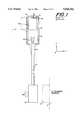
- FIG. 1shows a prior-art medical ultrasound transducer 1 in schematic sectional view.
- Transducer 1has a typically polymeric external case 2 which is gripped by the sonographer.
- the top of the transducer (+Y end)can be seen to have the typical acoustic lens 3 which serves to focus the ultrasound beam in the X-Y plane as it passes into the subject patient. Focusing in the Y-Z plane is done via electronic phase delays between the various piezoelements which are arranged on a Z-axis pitch and spacing passing into and out of the paper as is usual for phased array transducers.
- the bottom or back of the transducer 1has emanating from it a flexible coaxial cable bundle 4.
- the cable 4is shown in broken view at its midpoint to indicate its considerable length, usually on the order of 6 to 12 feet.
- a flexible strain relief 5Where cable 4 exits from the transducer 1, and specifically where it exits from the transducer case 2, can be seen a flexible strain relief 5. Strain reliefs are usually fabricated from a flexible rubber, such as silicone rubber, and they serve to prevent damage to the cable 4 or chemical leakage into the case 2 at the point of cable/case juncture particularly as cable 4 is flexed by the user.
- a transducer cable connector 6can be seen at the termination of the cable 4 (-Y end).
- the connector 6is usually of a mass-actuated design and has an appropriate rotatable actuation knob 8 for that function.
- To the right of the transducer's connector 6are shown in phantom a mating ultrasound system connector 7 mounted on an ultrasound system console 9.
- To use the transducer the sonographerwould plug connector 6 into mating connector 7 (connectors shown unmated) thereby electrically connecting the transducer 1 to the ultrasound system console 9.
- portions of numerous electrical interconnects 10run from the transducer device 1 into the cable 4 and, in turn, into the connector 6.
- interconnects 10comprising coaxial wires of controlled impedance are provided in cable 4 to carry the electrical impulses transmitted to and received from the individual piezoelements making up the phased array.
- the details of how the interconnects 10 are mated to the piezoelements or to the connectorare not shown as it is not critical to the understanding of this invention. It should be generally understood that numerous interconnects 10 pass from the transducer 1 and its piezoelements through the cable to the connector 6 and these serve an electrical function. Interconnects 10 must physically be routed through the interior of the back of the transducer case 2, and around whatever other means, thermal or otherwise, are located therein.
- the electroacoustic transducer device assembly 50is packaged and operated inside the confines of the polymeric case 2. Assembly 50 is shown schematically in FIG. 1 and in FIG. 7a. Assembly 50 comprises acoustic backer material 11, a piezoelements 12 and one or more (one shown) acoustic matching layers 13. Acoustic backer material 11 serves the functions of attenuating acoustic energy which is directed backwards to minimize reverberations and ringiness, and as a mechanical support for piezoelements 12. Materials used to fabricate backer 11 are generally poorly or only modestly thermally conductive as it is exceedingly difficult to design a highly thermally conductive yet acoustically highly lossy material.
- Piezoelements 12may, for example, be fabricated from lead zirconate titanate (PZT) or composite PZT in a manner well-known to one of average skill.
- PZTlead zirconate titanate
- the matching layer or layers 13which serve to act as an acoustic impedance transformer between the high acoustic impedance piezoelements 12 and the low acoustic impedance, human patient. (The human patient is not shown, but it should be understood that the patient is in contact with lens 3.)
- the piezoelement materialtypically PZT, is a ceramic having generally poor to modest thermal conductivity.
- the matching layer(s) 13 materialsalso frequently have poor to modest thermal conductivity because of their conflicting acoustic requirements.
- the backer 11, the piezoelements 12 and the matching layer(s) 13are all intimately bonded to each other and to the lens material 3 such that acoustic energy produced in piezoelements 12 may pass through the layer interfaces in the +Y-direction freely. Of course reflected acoustic echoes from the body may also likewise pass freely in the -Y direction, back into probe 1.
- Electrodesin any of the interfaces of the type between lens 3 and layer 13, layer 13 and piezoelements 12 or piezoelements 12 and backer 11. Adequate thin electrodes must be present to apply and sense electrical potentials across the top and bottom surfaces of the piezoelements 12. Electrical interconnects 10 are typically routed and connected to such dedicated interface electrodes on a piezoelement by piezoelement basis (connections and routing not shown). The interface or surface electrodes are required to make electrical contact to each piezoelements 12 without appreciably negatively impacting the acoustic performance spectrum of transducer 1. Thus, such electrodes are typically chosen to be very thin, metallic, and have very little mass. This, in turn, causes the electrodes to be poor thermal conductors in the lateral X-direction.
- thermal member 14is schematically shown physically and thermally connected to the edge region of element array 12 and layer 13, and possibly also to the ends of the interfacial or surface electrodes (not shown).
- Thermal member 15is schematically shown thermally and physically connected to member 14. The members 14 and 15 are arranged to be in close juxtaposition and in good thermal contact with the interior walls of case 2. It will be noted that thermal member 15 may typically be thicker (as shown) and therefor more thermally conductive than member 14 given the increased space toward the cable end of the transducer.
- items 14would consist of thin films of flexible copper, perhaps in the form of a flexible circuit, extending away from the edges of the piezoelement array 12 and possibly emanating from within an interface such as the interface between backer 11 and array 12, array 12 and layer 13 or layer 13 and lens 3 wherein it also serves an aforementioned electrode function.
- the primary purpose of member (or flex circuit) 14is electrical interconnection as necessary in the interfaces between at least certain of the laminated layers.
- Items 15would typically consist of aluminum or copper plates, perhaps between 0.010-0.080 inches thick, which are bonded or thermally coupled intimately to the inner surfaces of case 2. The joint between members 14 and 15 must be thermally conductive. If member 14 is an electrical flex circuit used for interconnection, then care would be taken to provide only a thermal joint and not an electrical joint so as not to short out the flex traces which need to be routed (not shown) backwards to interconnects 10.
- the system console 9transmits a series of electrical pulses through the connectors 7,6 and cable 4 to the acoustic array of piezoelements 12.
- the electroacoustic piezoelements 12convert the electrical pulses to acoustic output energy emanating from the rubber lens 3 into the patient.
- the piezoelementsenses in a passive mode the electrical disturbance produced by acoustic energy bounced off of internal patient tissue and reflected back into the transducer 1. It is primarily the transmit portion of imaging when heat is produced by the piezoelements. This is because the electroacoustic energy conversion process is less than 100% efficient.
- the piezoelements 12act as unintended heaters. Secondly, as ultrasound energy is produced by the piezoelements 12, it is somewhat absorbed by layers 13 and lens 3, such layers usually not being totally lossless. The unavoidable nonzero portion of acoustic energy which is directed away from the patient into the backer 11 also serves to generate heat in backer 11. Thus, we have heat being directly generated in the piezoelements 12 and indirectly generated in backing material 11, matching layer(s) 13 and lens 3.
- the purpose of member 15is to render isothermal the inner surface of the case 2 so that heat may be encouraged to flow across the case wall at all locations.
- the thermal purpose of member 14is to get the heat away from the piezoelements 12 and redirected so that it can be flowed into said isothermalization member 15. Using the combination of thermal elements 14 and 15 it has been possible to passively spread the heat out isothermally to most of the interior case 2 surfaces.
- case 2being fabricated of a polymer, will typically conduct heat poorly. It is therefore critical to get the heat spread out over most or all of the interior surface of case 2 so that although the thermal resistance across the thickness of the case wall 2 is high, there is considerable surface area to compensate for this fact and keep the overall thermal resistance between the elements and the environment as low as possible.
- Heat which is generated in matching layer(s) 13 and lens 3may also be conducted downward toward the piezoelements 12 or to their interfacial electrodes (not shown) which can, in turn, pass heat to the edges of the stack for redirection downward in the -Y direction via member 14 for example.
- transducer probe 1When transducer probe 1 is in contact with a patient's tissue, some heat may pass directly into the patient. In any event, the U.L. limitation on skin or tissue temperature severely limits the temperature of the lens, and heat dissipation toward the patient.
- Heat which is generated in backing material 11may be passed to thermal means such as member 15.
- Member 15may be arranged to actually envelope or wrap around backer material 11 in the form of a metallic thermal container or can (not shown) in order to facilitate the passage of heat from backing material 11 into thermal member 15 and out of transducer 1.
- probe 1the ability of probe 1 to shed heat to the environment is governed primarily by passive free convection of heat from the probe's external surfaces. There is a rather limited capacity to remove heat by natural convection of air past the external probe surface even in this optimal isothermalized example. In practice, given the limits on the temperature of lens 3 and sonographer gripping comfort, it is not possible to dissipate more than a few watts of thermal energy in this passive prior-art manner. Also, different sonographers typically cover different amounts of the probe surface with their hands as they grip it, and in some cases much of the heat is being transmitted by conduction directly into the sonographer's hand(s). This can produce sonographer discomfort and a poor grip.
- a copper braidcould be routed from the case 2 interior into at least some limited length of the cable 4 adjacent to device 1.
- This copper braided thermal meansmay be connected to a thermal means in the case such as depicted member 14, 15 or 14 and 15 or may also serve as item 15 for example. This tact essentially creates additional dissipative surface area on the cable.
- the second strategy for cooling transducerswhich, to the knowledge of the inventors, has not yet been pursued by any medical ultrasound vendor, is to utilize active cooling rather than passive cooling in order to dissipate heat well beyond that which can be passively convected or conducted from the external transducer surfaces.
- Active coolingmeans that one provides a means to actively remove heat from the transducer such as by employing a pumped coolant or other active refrigeration means.
- active coolingone may ensure that one is always able to operate the acoustic transducer up to the allowable acoustic intensity limit while also maintaining acceptable surface temperatures regardless of how small the transducer is or how much surface area it offers for cooling relative to its acoustic intensity.
- any active cooling schemeshould preferably continue to allow for the freedom to do this and should not substantially complicate the integrity or ease of this connection. Large numbers of connector plug/unplug cycles should also not degrade the performance of the active cooling means. Any active cooling scheme should involve minimal additional maintenance and should be as transparent to the user as possible.
- a further object of the inventionis to provide a plurality of active cooling embodiments, wherein each design represents a novel and reasonable balancing of the many constraints mentioned above.
- thermoelectric cooling devicewhich is electrically actively driven.
- an ultrasound transducer assemblyhaving a housing, a transducer array mounted in the housing, and active cooling means positioned adjacent to the transducer array for actively removing heat generated by the array by transport of heat energy from the affected site.
- the active cooling meansmay comprise a heat exchanger including a flowed coolant in a closed-loop, multipass circulating coolant system or single-pass flowed coolant, the coolant passing through the heat exchanger, a heat pipe, a thermoelectric cooler, an evaporator/condenser system, and/or a phase change material.
- one or more heat exchangersmay be used having gas or liquid coolants flowing therethrough. Open, single-pass and closed-loop, multi-pass coolant systems may be used.
- the heat exchangers and coolant pumpsmay be located in various components of the transducer assembly, including the array housing, the connector assemblies or the ultrasound console.
- the active and semiactive means disclosed hereinmay be driven or allowed to operate as part of a feedback loop wherein a probe temperature is maintained at a desired level or below a limit value.
- a probe temperatureis maintained at a desired level or below a limit value.
- temperaturewould be sensed and that data used to determine the extent of the application of the active or semiactive cooling or thermal control means to achieve the thermal goals of the product as it operates.
- the temperature control meansmay easily use to also heat the probe such that it is warm and comfortable to the patient's touch when first used. Alternatively one might ensure that the probe operates at all times at a desired temperature setpoint (including when the probe is first switched on) or below such a setpoint or above a lower setpoint and below a second higher setpoint. Any scheme wherein heating is involved would include adding a heater means to our described coolant loops. The thermal control means might also be used to cool the probe to prevent damaging it during hot disinfection or sterilization procedures used to clean the probe.
- a further embodimentincludes implementing improved passive thermal conduction materials for coupling to standard passive thermal conductors and/or active means.
- liquid-filled deformable bagsare provided within the transducer which efficiently couple heat between irregular surfaces, but allow for easy disassembly for servicing of heat-dissipating electronics in the transducer.
- FIG. 1is a partial cross-sectional view of a typical industry-standard, solid-state, phased array transducer with its accompanying cable, system connector, system-console, mating connector, and typical passive heat distribution plates.
- FIG. 2ais a partial cross-section of a first embodiment of a device incorporating the active cooling elements in accordance with this invention wherein a gaseous coolant, such as air, is forced by pumping or pressurization means located at or near the connector/console end of the transducer cable through the cable into the device.
- a gaseous coolantsuch as air
- FIG. 2bis a partial cross-sectional view of a second embodiment of a device in accordance with the present invention similar to the arrangement of FIG. 2a but where the gaseous coolant, such as air, is instead drawn into the probe and passed along the cable toward the console in the opposite direction to that of FIG. 2a.
- gaseous coolantsuch as air
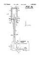
- FIG. 3ais a partial cross-section of a third embodiment of a probe device in accordance with the invention wherein the probe contains a heat exchanger for active cooling and a miniature fan or other coolant-moving pump means to forcibly pass coolant by a probe heat exchanger.
- FIG. 3bis a partial cross-sectional view of a fourth embodiment, similar to the arrangement of FIG. 3a, but wherein a gaseous coolant, such as air, is drawn into the probe across the heat exchanger and then expelled from the probe through nearby probe exhaust ports.
- a gaseous coolantsuch as air
- FIG. 3cis a partial cross-sectional view of a fifth embodiment, similar to the arrangements of FIGS. 3a and 3b, but wherein a coolant exhaust path is provided which ejects a gaseous coolant, such as air, from ports located comfortably away from the sonographer's hand.
- a coolant exhaust pathis provided which ejects a gaseous coolant, such as air, from ports located comfortably away from the sonographer's hand.
- FIG. 3dis a partial cross-sectional view of a sixth embodiment wherein a closed loop cooling system is provided, utilizing either liquid, gas or other flowable coolant, wherein a probe heat exchanger passes heat into said cooling loop for transport down the cable.
- FIG. 3eis a partial cross-sectional view of a seventh embodiment similar to that of FIG. 3d, wherein the closed coolant loop passes into the system console through the connector interface.
- FIG. 4is a partial cross-sectional view of an eighth embodiment wherein a thermoelectric cooling device is thermally coupled to the heat dissipating piezoelements and their local associated passive heat dissipating members.
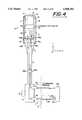
- FIG. 5is a partial cross-sectional view of a ninth embodiment of a device in accordance with the invention wherein a flexible and generally tubular heatpipe is utilized as the active cooling component.
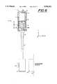
- FIG. 6is a partial cross-sectional view of a tenth embodiment of the device in accordance with the invention wherein a material having a large phase-change heat absorbing capacity is placed in the probe and thermally coupled to the dissipating device.
- FIG. 7ais a side view of a piezoelement transducer assembly of the type used in the device shown in FIG. 1.
- FIGS. 7b-7dare cross-sectional views of a piezoelement transducer assembly comprising further embodiments of the invention providing enhanced passive thermal means for spreading out the concentrated heat being generated in and near the piezoelements through application of thin-film diamond.
- FIG. 8is a cross-sectional view of a twelfth embodiment of the invention including cooling plates and a transducer assembly which contains supporting electronic circuitry which passively dissipates concentrated heat along with hermetically sealed liquid-filled bags which serve to transport heat across the highly irregular interfaces between the electronics and the plates.
- FIG. 2ashows a first embodiment of the invention which is generally externally similar in overall structure to the transducer probe 1 shown in FIG. 1. Elements in probe 1 and 1A having like construction are designated with the reference materials set forth in FIG. 1.
- Probe 1A of FIG. 2aincludes a heat exchanger 16 having internal heat exchange fins 17. It will be noted that there is a flow of coolant gas 21 into heat exchanger 16 from tube 20 in cable 4. Exhaust or coolant gas exit ports 18 vent the coolant gas 21 to the atmosphere after it has absorbed heat from heat exchanger 16 and fins 17. It will be noted that the heat exchanger 16 is arranged to be in intimate thermal contact with the passive thermally conductive members 15.
- a coupling fitting 19such as a snap-lock pneumatic fitting with an O-Ring, is shown providing a generally airtight connection between the portions of tube 20 and the connectors 6 and 7.
- Connector 19would most likely have a male and a female portion wherein the male portion is mounted to either connector 6 or 7 and the female portion to the remaining connector.
- the connectorsare mated electrically, they are thus also mated pneumatically in a manner to connect the gaseous coolant source in the system to the probe.
- a pressurized coolant source 100whose positive pressure forces gaseous coolant in the form of flow 21 through tube 20 toward and into case 2.
- Transducer 1Awould not be subject to liquid coolant spills, dripping connections, or coolant fluid level monitoring when a gaseous coolant is used.
- Airis an advantageous gaseous coolant because it does not necessarily have to be provided in the form of a tank or reservoir as with bottled gases.
- the indicated pressurized coolant source 100may consist of a compact and efficient air pump of any design desired, including positive displacement designs, turbine designs, rotor designs and fan designs. The air being pumped by the pressurization source would be drawn from the environment in these cases.
- pressurized coolant sourcewe broadly mean any possible source of pressurized gas, including pressurized air bottles (cylinders) or bottles of any other gases such as nitrogen or helium.
- FIG. 2ashows a pressurized gas source in the system console 9, one may alternatively place the gas source means in connector 6, in connector 7 or even external to the probe/cable/connector/console hardware.
- a tube or conduit of the type 20will be provided in a manner which causes the sonographer minimal inconvenience.
- the sonographerdoes not physically see any component of the coolant system.
- the least reliable portion of the cooling system which might need repairis the pressurization source 100 which is located in the system 9 (or alternatively in connectors 6 or 7) where it can be serviced without disassembling the transducer probe 1A.
- exhaust ports 18are shown on the sides of probe case 2. These exhaust ports may alternatively be placed anywhere, and may be connected to the heat exchanger via additional conduit or tubing (not shown). In order to minimize pressure drops, it is typically best to minimize the length of the tubing; the design shown achieves this by directly dumping the heated gas to the environment.
- Onemay utilize filters, mufflers, and/or gas diffusers (not shown) to keep the gas clean so as not to foul the internal coolant paths, so as to silence or muffle flow noise and so as to redirect or spread out the exiting gas stream such that it does not bother the sonographer in any way.
- the gas delivery conduit or tube 20may enter the probe at a location other than emanating from the interior of cable 4.
- Yet another alternative to this approachincludes providing heat exchanger 16 on the outside of case 2 along with conduit 20, where each may be electively detached. In all of these cases, a heat exchanger 16 is provided at the transducer 1A and connected to a gas source 100 outside of the transducer 1A.
- a high pressure flexible tube 20 having a diameter of approximately 0.050-0.125 inchesis suitable for use.
- Tube 20may be fabricated of polyimide, for example, in which case a fairly thin wall thickness of from 0.004-0.012 inches may be used.
- Easily coupled gas fittings 19are also readily available, including those from the product lines of Swagelock Company (31400 Aurora Road, Solon, Ohio 44139), Parker Hannifin Corporation (8145 Lewis Road, Minneapolis, Minn. 55427), and Colder Products Company (1001 Westgate Drive, St. Paul, Minn. 55114).
- FIG. 2bshows a second embodiment of the invention.
- this embodimentis similar to the embodiment shown in FIG. 2a, however the coolant gas 21A is flowing in the opposite direction from that disclosed in FIG. 2a--i.e., into the transducer probe 1B, through heat exchanger 16, into tube 20, through connector halves 6 and 7, and into ultrasound console 9 and a coolant suction source 101.
- Coolant suction source 101may be any convenient suction or negative gauge pressure source such as a compact vacuum pump, suction pump, vane pump, rotary pump or positive displacement pump.
- An advantage of this arrangement over that of FIG. 2ais that one does not have to deal with warmed exhausted coolant gas at the probe which may, on occasion, be a noise problem, a comfort problem or might disturb a surgical site.
- a disadvantage relative to FIG. 2ais that one may only apply one atmosphere of gage suction pressure or about 14.7 psi wherein the FIG. 2a device may utilize several tens of pounds of positive pressure.
- the pumping devicein this case the suction source 101, may be placed closer to the probe 1 such as in connector half 6 or 7 or elsewhere externally to the probe/cable/connector/console.
- Tube 20may also be routed directly to the probe case 2 from other than the cable 4 interior.
- heat exchanger 16having internal “fins” 17 has been described. It is to be stressed that included in the scope of this invention is the use of any heat exchanger capable of passing heat into a passing gas stream. For example, one might utilize a heat exchanger based on an array of metal tubes, an array of metal pins or even a porous metal. "Heat exchanger” is herein defined as any means, including any directly associated containments necessary to direct the coolant flow over the fins or their equivalents, which can pass heat from an adjacent coupled heat source to a forced or pumped coolant stream.
- piezoelements 12are many in number and are arranged on a pitch in the Z axis to achieve their basic acoustic array function. Their arrangement is actually much like an array of fins and one may thus force the coolant gas through them (through the spaces or kerfs between them) to form a heat exchanger 16 integrated directly and intimately with the acoustic means.
- a fin 17may itself be a heat producing piezoelements 12.
- a more common case of partial integration of exchanger 16would be where the portions of the case 2 serve to direct and contain the coolant flow over metal fins 17.
- Specific pressurization/suction means 100 and 101 suitable for use with the embodiments shown in FIGS. 2a-2binclude the following: EG&G Rotron (7 Hasbrouck Lane, Woodstock, N.Y. 12498), Gast Manufacturing Corporation (2300 Highway M-139, Benton Harbor, Mich. 49023-0097), and Ametek (627 Lake Street, Kent, Ohio 44240) offer regenerative continuous flow blowers which can generate 10-100 inches of water-pressure head or suction column; and Medo U.S.A., Inc. (808-A North Central Avenue, Wood Dale, Ill. 60191) offers positive displacement interrupted flow pumps which can generate very high pressures.
- FIG. 3ashows a third embodiment of the invention.
- the source of the gas pressure difference driving the flow(the pressurization or suction means) is relocated to the interior of the transducer probe case 2.
- FIG. 3ashows an air pump 22 (a pressurization source) inside of case 2 or probe 1C.
- Air 21Bis drawn into the probe from the environment through ports 18 at the back of the probe by the internal air pump 22.
- Air pump 22is shown forcing the air stream 21B into the heat exchanger 16 and through its internal fins 17.
- Air coolant stream 21Bthen exits from additional ports 18 carrying heat with it in the manner described with respect to some of the previous figures.
- heat exchanger 16is in intimate thermal contact with passively conducting member 14 and 15 which can transport heat to exchanger 16 from dissipating piezoelements 12.
- air-moving pumps 22 for use in probe 1Cinclude those available from Nidec Corporation (100-T Franklin Drive, Torrington, Conn. 06790) and U.S. Toyo Fan Corporation (4915 Walnut Grove Avenue, San Gabriel, Calif. 91776). These vendors offer low-profile, tube-axial continuous flow devices. These example devices are characterized by moderate pressure generation and utilization of brushless DC motors.
- Alternative air-moving devices suitable for use as pump 22are available from EG&G Rotron (7 Hasbrouck Lane, Woodstock, N.Y. 12498), Micronel U.S. (1280-D Liberty Way, Vista, Calif. 92083) and Labinal Components and Systems, Inc. (2275 Stanley Avenue, Dayton, Ohio 45404).
- vane-axial continuous flow devicesare characterized by moderate pressure generation in the range of 1-2 inches of water pressure, 24 volt DC power sources and operation at 15k-20k RPM.
- a tube or conduit 20 in the cable 4 nor a pressurized gas connector 19are required.
- Air-pump 22will typically require electrical power which may be delivered via electrical wires or traces passing through cable 4 from ultrasound system 9. Alternatively, the electrical power may be delivered through separate wires not contained in cable 4.
- An alternative within the scope of the embodiment shown in FIG. 3aincludes mounting air pump 22 and/or heat exchanger 16 on the external surface of case 2. In any event, heat exchanger 16 will always be arranged to be in intimate thermal contact with a means such as thermal member 15. In the case of external mounting of heat exchanger 16, thermal member 15 would be arranged to pass heat across the wall of case 2 with little loss. To do this, member 15 may be required to penetrate case wall 2 in a hermetic manner.
- FIG. 3bshows a fourth embodiment of the invention, similar to the embodiment of FIG. 3a, except that the coolant flow 21C is in the opposite direction.
- This approachmay offer advantages when exhausting the coolant gas from the back (-Y end) of transducer 1D is important, to keep it away from the sonographer's hand.
- the ports 18 serving as exhaust portsmay also be on the bottom surface (-Y end) of the transducer adjacent the strain relief 5.
- the intake ports 18may be anywhere which is convenient.
- the air pumping or suction means 22Amay be arranged to be operated in either flow direction 21C (or 21B per the previous FIG. 3a) per the user's selection. An electrical switch may be provided for this purpose.
- FIG. 3cshows a fifth embodiment of the invention, similar to that in FIGS. 3a and 3b. Coolant flow 21C is shown entering and being drawn into probe 1E at intake ports 18 toward the heat exchanger 16, through the air pumping or suction means 22A, and subsequently exiting the probe 1E as flow 21C through internal exhaust ducts 18A inside the strain relief 5. It will be noted that the warmed exhausted coolant gas 21C is directed along the cable 4 away from the sonographer's hand.
- the internal detail of strain relief 5is such that one or more gas exhaust ducts 18A are provided while maintaining some peripheral support to the cable.
- the exhaust ducts 18Amay be arranged to be closable or sealable, if desired, when the probe is temporarily immersed in disinfectant for cleaning. (This is true for all intake and exhaust ports for any of the embodiments.) Alternatively, one may arrange any of the disclosed designs such that ingress of disinfectant into intake and exhaust ports 18 or 18A may be tolerated, such as by ensuring the use of noncorrosive metals where disinfectant ingress takes place. It should be readily understood that one may alternatively utilize the embodiment shown in FIG. 3c with the coolant flow proceeding in the opposite direction. Miniature fans and motors which may be sterilized are commercially available, so the design challenge becomes more one of disinfecting or sterilizing, with less of a concern about damage caused by such processes.
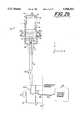
- FIG. 3dshows a sixth embodiment of the invention wherein a completely closed-loop cooling system is contained entirely within the probe/cable/connector assembly 1F. It will be noted that there are no coolant conduits or coolant connections made across the connector interface to the ultrasound console 9 or console connector 7.
- the coolant utilizedmay be a liquid, a liquid slurry or a gas. Most preferably, the coolant will have a liquid phase.
- the coolantmay be a liquid, such as water or ethylene glycol, or any liquid suitably utilized in closed loop coolant systems. Precautions should be taken with any liquid used to prevent corrosion and minimize bacterial growth.
- phase change ingredient within the slurrymay, for example, consist of 15 micron diameter phenolic-encapsulated n-eicosane particles which are carried in distilled water. This slurry or particle/water mix has a thermal capacity of about seven times that of water alone.
- Eicosaneis a paraffin wax with a 20 carbon chain that liquifies at 36.6 degrees centigrade.
- a heat exchanger 16Ais provided internal to case 2 to transport heat from the transducer components such as 14 and 15 into the heat exchanger 16A.
- Coolant input tube 20Apasses an inflow of coolant 103A into the heat exchanger 16A and across the fins 17A of heat exchanger 16A.
- the coolantafter picking up heat from the fins 17A, passes out of the heat exchanger 16A in the form of outflow 103B into a second tube 20B.
- tubes 20A and 20Bare shown running the length of the transducer cable 4 back to probe connector 6.
- cable 4might be of a somewhat larger diameter than in previous embodiments as it now contains two coolant tubes.
- Exchanger 16Acontains internal ducting (not shown) and/or manifolds which are necessary to distribute and route the coolant over fins of the type 17A in the most efficient manner.
- arrowsschematically indicate incoming (103A) and outgoing (103B) coolant flows.
- tubes 20A and 20B(within cable 4) are thermally decoupled from each other such that the coolant inflow 103A is not undesirably preheated by exiting coolant outflow 103B.
- Connector 6includes, in addition to the expected electrical interconnection means (not shown), a coolant pump 102 and a second heat exchanger 16B.
- a segment of tubing 20Cconnects pump 102 to the heat exchanger 16B such that the coolant may flow from pump 102 to the exchanger 16B in the form of coolant flow 103C as shown.
- the coolant flow rates in the indicated flows 103A, 103B and 103Care essentially all equal.
- Pump 102may be powered electrically, mechanically or pneumatically. In the case of electrical powering, it may receive its electrical energy from the system console 9 via one or more electrical contacts in connectors 6 and 7.
- Heat exchanger 16Bis preferably a liquid-to-air heat exchanger. That is, liquid to be cooled is flowed inside of exchanger 16B and air on the outside of exchanger 16B, which is either naturally convected or forced across exchanger 16B, carries the heat away.
- Exchanger 16Bmay consist of a radiator (shown) or a fan and a radiator combination (not shown), for example. In an alternative approach, both a fan (not shown) and pump 102 (shown) would receive electrical power from the console 9 through the connectors 6 and 7. Sources for fans and pumps suitable for use in accordance with the embodiment of FIG. 3d have been previously described.
- return tube 20Bin the cable 4 such that its contained returning coolant 103B may easily pass its heat to the atmosphere via natural free convection from the surface of cable 4.
- cable 4is quite long and substantial cable surface area is available to do this. If the return tube 20B is arranged in the cable 4 to be near its surface and a metallic shroud is provided near the outside surface of cable 4 which is in thermal communication with tube 20B (which shroud may double as an electromagnetic shield) the return tube 20B may pass its heat to the metallic shroud such that the surface (or subsurface) of the cable 4 is warmed and made to act as a radiator itself.
- a feedback loopmay further be included in this (or any other) embodiment of the invention, wherein a temperature sensing function triggers variations in the degree of the coolant system's operational capacity in order to control (by maintaining, rising above or dropping below) particular temperature set points.
- a temperature sensing functiontriggers variations in the degree of the coolant system's operational capacity in order to control (by maintaining, rising above or dropping below) particular temperature set points.
- FIG. 3dit should be readily understood that one may vary the speed of pump 102 or the speed of a fan associated with heat exchanger 16B (not shown), for example, to control temperature at a desired level.
- tubing 20A and 20Bmay be flexible, unreinforced or reinforced, polymer tubing such as polyimide tubing.
- Tubing 20C in connector 6may be rigid as it does not have to flex with the cable. Portions of the tubing in probe case 2 may also be chosen to be rigid. It should also be emphasized that the direction of the flow may be opposite that which is depicted in FIG. 3d and the order of appearance of components 102 and 16B as the coolant flows through them may be changed as desired. (For example, the pump 102 might be downstream of the exchanger 16B.)
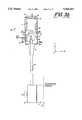
- FIG. 3eshows a seventh embodiment of the invention which is similar in construction to the embodiment shown in FIG. 3d.
- pump 102 and heat exchanger 16Bare located in ultrasound system console 9 (shown) or, alternatively, in console connector 7 (not shown).
- console connector 7In order to implement the closed loop cooling system in this manner one may provide coolant couplings or connectors 19 in mating probe and console connectors 6 and 7 as shown.
- connectors 6 and 7may incorporate both the electrical connections (such as for interconnects 10) and coolant connectors 19.
- Onemay alternatively choose to use non-integrated, independent connectors for the electrical connectors 6 and 7 and the coolant connections 19 (not shown).
- FIG. 3eshows pump 102 resident in console 9 along with the heat exchanger 16B.
- the tube connecting pump 102 and the heat exchanger 16Bis again indicated as tube 20C having an internal coolant flow into exchanger 16B indicated again as 103C. Again the coolant flow rates of depicted flows 103A, 103B and 103C would typically be equal.
- FIG. 3eAdvantages of the design of FIG. 3e are that one may use a larger and more powerful pump 102 and/or heat exchanger 16B.
- Heat exchanger 16Bmay again be accompanied by a fan (not shown) in the console 9.
- console 9would contain the other independent coolant loop (not shown).
- a liquid-to-liquid exchangergenerally has a much higher capacity than a liquid-to-air exchanger of the same size.
- FIG. 3eAn alternative contemplated within the scope of the invention is the design of FIG. 3e wherein, in order to avoid coolant spillage, one arranges the coolant such that, when the transducer 1G is not plugged in, there is no coolant at connectors 19. In this manner, plugging and unplugging connectors 6 and 7 (and therefore connectors 19) will not result in any spillage of coolant.
- console 9may cause the coolant system to eliminate all air in the coolant path as by venting.
- FIGS. 3d and 3ecould utilize a liquid or liquid phase-change coolant, or even a gas coolant.
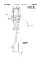
- FIG. 4shows an eighth embodiment of the invention.
- FIG. 4depicts a system similar to that of FIG. 3e but with a thermoelectric cooling device 30 in the thermal path between passive conducting members 15, 15A and heat exchanger 16A.
- the thermal member 15Aextends beneath acoustic backer 11 such that heat may be deposited in the top cooling surface (+Y surface) of thermoelectric cooler 30.
- Cooler 30would typically consist of an electrically powered junction device capable of establishing a thermal gradient and transporting heat through its thickness along the Y axis (sometimes referred to as a Peltier device). Such devices, although capable of moving appreciable quantities of heat, are typically rather inefficient.
- thermoelectric coolers 30are available to carry away not only the piezoelement heat pumped by cooler 30, but also the waste heat generated by the cooler 30 itself.
- thermoelectric coolers 30are available, for example, from Marlow Industries, Inc. (10451 Vista Park Road, Dallas, Tex. 75238) with heat removal capacities covering the range from 1 to 150 watts.
- the cold (cooling) side of cooler 30may, depending on the heat load and specific type of cooler, have the capacity to subcool between 10 and 100 degrees centigrade.
- Use of a thermoelectric cooler 30offers advantages of dynamic realtime temperature control of the transducer piezoelements and/or the thermal capacity to actually subcool the piezoelements 12 as described without requiring a conventional freon-style refrigeration system.
- the readerwill realize that the thermoelectric cooler 30 may be arranged to dump its heat to any of the other thermal means of the system embodiments described herein.
- thermoelectric cooler 30A specific advantage of a thermoelectric cooler 30 is appreciated when performing high frequency ultrasound imaging of near-surface tissues. In these growing applications, increasing amounts of heat energy are being generated in the probe and in the tissue as manufacturers attempt to achieve the highest possible resolution at the maximum allowable acoustic intensities. It would be rather difficult to maintain a reasonable lens temperature unless a cooling device 30 having very large cooling capacity (a device capable of subcooling may serve this purpose) is present in close proximity to the piezoelements, lens and tissue.
- FIG. 5depicts a ninth embodiment of the invention.
- a flexible tubular heat pipe 23is thermally connected via thermally conductive member 24 to the previously described thermal member 15.
- Heat pipe 23extends into cable 4 for a fair length, perhaps a foot or more, and is thermally coupled to the outer jacket of cable 4 within such length.
- conductive memberswhich pass into cable 4 from the interior of case 2, and internal thermal members such as 15 and 14.
- Heatpipe 23may also be very flexible.
- heatpipe 23may be external to the cable in some cases.
- Such an external heatpipe 23could be draped to the side of the probe during use.
- Such an external pipecould also have an attached radiator surface, for example.
- Meanscould be provided for such an optional heatpipe to alert the ultrasound system that the external heatpipe means is plugged in and that higher acoustic power levels are allowable without fear of thermal problems.
- Heatpipe 23may also extend all the way back to connector 6 in cable 4.
- Heatpipe 23may be a classic heatpipe in that it uses an internal wick structure to return the coolant fluid to the hot spot after the coolant vapor recondenses to said fluid phase in the cooler region of said heatpipe 23.
- systems suitable for use as heatpipe 23include evaporation/condensation systems not necessarily involving a wick structure dedicated to capillary pumping of recondensed coolant back to the heat source.
- a system called the OasisTM system produced by Aavid Engineeringconsists of an evaporator (which is thermally coupled to the user's device to be cooled) and a separate condenser panel. The evaporator is connected to the condenser by two tubes.
- the evaporatorIn a manner similar to the heat pipe, the evaporator generates a liquid vapor in response to the heat input.
- the heated vaporflows through one of the tubes to recondense back into the liquid phase in the condenser panel.
- the recondensed fluid in the condenser panelis returned to the evaporator through the second tube in liquid form.
- FluorinertTM fluidwhich has a boiling point of 57 degrees centigrade.
- the evaporatornever gets hotter than 57 degrees centigrade because a phase change from liquid to vapor takes place at that temperature.
- FIG. 6shows a tenth embodiment of the invention.
- a container 25is provided in case 2 in intimate thermal contact with thermal members 15.
- an optional movable preloaded diaphragm 25Ais shown which is slidable in the +-Y direction and capable of applying modest downward (-Y direction) pressure.
- Adjacent to and in contact with slidable diaphragm 25Ais a phase-change material which is depicted in both of its operational forms 26A and 26B.
- the phase-change materialis a material which absorbs a very large amount of heat when its phase changes from one phase to the other.
- H 2 Otakes the form of water and ice at 0 degrees centigrade and to totally convert from one form (phase) to the other for a given quantity of H 2 O requires a considerable flow of thermal energy.
- This flow of energydoes nothing to change the temperature of the water/ice mixture from 0 degrees centigrade while this phase-change is taking place.
- one's drinkcan be kept cold as long as ice is present.
- This property of absorbing a large quantity of thermal energy without changing temperaturecan be very useful if the temperature in question is of technical use.
- phase change materialmay absorb a substantial quantity of heat without changing temperature (getting any hotter) and without the need to pass the heat to the environment immediately.
- the phase change materialwill absorb the waste heat and keep the probe at the acceptable phase-change temperature.
- the phase change materialis therein acting essentially as a thermal capacitor which is either charging (absorbing heat) or discharging (dumping previously absorbed heat).
- phases 26A and 26Bmay, for example, be a molten phase and phase 26A a solid phase.
- Probe 1Jis depicted at a moment in time when the phase-change material is partially converted from one phase to another.
- waste heatis flowing down thermal member 15 and into the left and right sides of container 25 whereupon the heat causes the molten phase 26B to first form adjacent to each thermal plate 15. Since not enough heat has yet flowed into the container 25 there is still a region in the middle of the container 25 where the solid phase 26A of the phase-change material is still present.
- the remaining region of solid phase-change material 26A in that central portion of container 25would also become molten.
- the container 25 and its contentscan no longer absorb heat at the constant phase-change temperature and further heat input will only result in the container 25 and probe 15 getting hotter.
- the slidable pressurizing diaphragm 25Aapplies a constant pressure for the purpose of urging the phase-change material to remain in contact with the internal walls of container 25 as the phases change back and forth. This is necessary because many phase-change systems are accompanied by small but not insignificant volume changes.
- a phase change material useful for container 25would be a wax-like substance having a deformable waxy solid phase and a liquid phase. Slidable diaphragm 25A could keep the two phases of such a wax-based system from growing voids or air pockets during phase changes due to volume changes.
- Specific phase change materials for use in the FIG. 6 systeminclude the series of paraffin waxes of which eicosane is one.
- Paraffin waxes with hydrocarbon chains of between about 18 (octadecane) and 22 carbon atomshave melting points between 25 and 41 degrees centigrade. Specifically, octadecane has a melting point of 28.1 degrees centigrade and a heat of fusion of 58.2 calories per gram. Eicosane (20 carbons) melts at 36.6 degrees centigrade and has a heat of fusion of 59.1 calories per gram. These two materials experience only about a 7% density change during melting and freezing thus the concern about volume changes may be minimized.
- phase change material systemsmay be considered for use in probe 1J. Some of these undergo sublimation/evaporation.
- Other heat-of-fusion, phase-change material systemsinclude hydrated inorganic salts (e.g. zinc nitrate which melts at 36.2° C. and has a heat of fusion of 31 cal/gm), anhydrous inorganic salts (e.g. metaphosphoric acid HPO4 with specs of 42.5° C. and 25 cal/gm) and compounds such as Glauber's salt (Na 2 SO 4 .10H 2 O which changes phase at 32.2° C.).
- the wax systemsare preferred because there is minimum chance of phase separation. Indeed, tests have been reported wherein the above wax materials have been phase-cycled as many as 30,000 times without any change in thermal capacity.
- container 25phase-change heat-accumulation device. Once it is filled with heat (the beneficial phase change has run its course), its heat absorption characteristics are no longer beneficial in probe 1J. However, in typical operation of transducer devices, there are frequent occasions when short-duration excessive heatflow is generated. In such cases, container 25 may be beneficial as a thermal reservoir. During other portions of the probe's operation, when heat flow is more typically at a lower level, other cooling means of the probe (such as the prior art passive convection means) may be utilized to gradually allow the material in phase 26B to revert back to the solid phase 26A, as well as to cool the probe in the normal manner.
- other cooling means of the probesuch as the prior art passive convection means
- a very high power modea mode which cannot practically be cooled in real time even by aforementioned air pressurization or suction means, wherein most or all of the excessive heat is dumped into the phase change material.
- Hyperthermiathe use of directed heat to treat or kill cancerous cells in bodily tissue, could be an obvious application of any of the means of this invention and particularly of the high-capacity phase-change and thermoelectric means possibly coupled and integrated with means such as those depicted in earlier FIGS. 2a,2b,3a,3b,3c,3d,3e and 5.
- the imaging transducer probe 1to both image (locate and target) the cancerous regions and, when targeted, deliver intense heating ultrasound or sonic energy to the cancerous tissue within the body.
- the ultrasound console 9may be arranged so that it automatically, via software, has the intelligence to keep track of the cancerous sites and their integrated thermal dosages despite some amount of unavoidable movement of the transducer.
- thermoelectric and phase-change components of the inventionwould be suitable to prevent overheating to the patient or sonographer in such instances.
- a further aspect of the present inventionaddresses the problem of circumventing the two thermal chokepoints commonly found in transducers. These chokepoints are related to areas where heat is being generated in a concentrated manner in a small space. What is required is to spread this concentrated heat out so that it can be more easily coupled into the active thermal means of the previous figures (or into any other means including the prior art means).
- carbon-based matching layershave been used which have acceptable acoustic properties, somewhat better than mediocre thermal properties, but problematic handling (very brittle) and adhesion properties.
- the heat transmission problemis exacerbated in that the large piezoelement array is generating greater amounts of heat, and the distance from its center to its edges is even greater. This can lead to the emitting aperture having a hot spot in the middle despite the best effort to remove the heat at the edges.
- FIGS. 7b-7dshow variations on an eleventh embodiment of the invention.
- FIG. 7ashows the electroacoustic transducer device 50 of the previously depicted probes 1A-1J consisting of acoustic backer 11, piezoelements 12, matching layer(s) 13, and passive thermal members 14 and 15 (15 not shown).
- FIG. 7bis an enlarged view of transducer assembly 55A, similar to assembly 50, but with unique differences outlined below.
- a new material layer 27is shown situated on top of matching layer(s)13.
- layer 27is seen therein shown situated at the interface of the matching layer(s) 13 and piezoelements 12.
- material layer 27is shown situated between the acoustic backer material 11 and piezoelements 12.
- the added material 27is also shown situated on the surface of each thermal member 14.
- Material 27is a thermal enhancement layer consisting of a film of diamond or diamond-like carbon-based material which is either deposited on one or more of the acoustic components or laminated to the acoustic components.
- Preformed diamond filmsalready deposited and formed, may be procured from companies such as Diamonex, Inc. (7150-T Windsor Drive, Allentown, Pa. 18106-9328) and Norton Company, Materials Division (1-T New Bond Street, Worcester, Mass. 01615-0008). Whether purchased as a component or deposited by the transducer builder the growth of diamond films frequently utilizes methane-based or other hydrocarbon-based plasma or arc-jet processes.
- Some of these processesare high temperature processes suitable only for deposition on a ceramic such as PZT, vitreous carbon or graphite and others are suitable for low temperature deposition even on plastics such as on acoustic matching layers.
- Diamond films or "substrate” materialstypically have 4 to 7 times the thermal conductivity of copper. Thus, for a diamond film having 5 times the thermal conductivity of copper, the same net heat-carrying capacity as copper is achieved at only 1/5th the thickness of the thermally equivalent copper.
- diamond film 27is utilized on a surface to which electrical contact must be made, either the diamond film can be doped to be electrically conductive, or contact vias may be provided through the diamond film so that electrical interconnections may pass through the diamond layer(s) 27.
- diamond films 27 in the transducer to conduct heatare contemplated as being within the scope of the invention.
- any mechanical constraint the diamond film(s) present to the vibrating piezoelements 12, assuming the diamond film(s) 27 touches the elements 12,must be taken into account in the acoustic design. This is very critical for large aperture high power modes of operation wherein it is otherwise difficult to avoid creating a hot-spot in the middle of the acoustic aperture (at the element midpoints for example).
- FIG. 8depicts a novel solution to a second thermal chokepoint of modern transducers. This improvement spreads concentrated heat into any convenient thermal sinking means, including into those of the prior art, or into any of the active means of this invention.
- two printed circuit boards or substrates 28, each supporting electronic components 29,are mounted back-to-back in the case 2 of transducer 1.
- the boards 28 and components 29may, for example, consist of multiplexing electronics, amplifiers, matching electronics, computational and/or memory electronics or any other electronic or heat-producing subsystem used in the operation of transducer 1.
- Liquid-filled bags 31are deformably squeezed between each board 28 and component 29 subsystem, and thermal member 15.
- Such fluid-filled and hermetically sealed deformable bags 31may be obtained from 3M Industrial Chemical Products Division (Building 223-6S-04, 3M Center, St. Paul, Minn. 55144-1000). It will be noted that the surface of each board subsystem has an irregular surface shape due to components 29 mounted upon them and that bags 31 conform nicely to said irregular surfaces thus insuring maximal thermal contact. Bags 31 are typically metalized polymeric bags containing 3M FluorinertTM thermally-conductive liquids. Thus, heat may freely flow out of the components 29 directly into contacting and juxtaposed bag 31, and then from bags 31 into plates 15. The great advantage of bags 31 is that one may easily disassemble board 28 and components 29 from the transducer 1K at any point in time to service the transducer without having to deal with the removal of the alternative and messy thermally-conductive potting compounds.
Landscapes
- Engineering & Computer Science (AREA)
- Life Sciences & Earth Sciences (AREA)
- Health & Medical Sciences (AREA)
- Physics & Mathematics (AREA)
- Surgery (AREA)
- Animal Behavior & Ethology (AREA)
- Radiology & Medical Imaging (AREA)
- Nuclear Medicine, Radiotherapy & Molecular Imaging (AREA)
- Biomedical Technology (AREA)
- Heart & Thoracic Surgery (AREA)
- Medical Informatics (AREA)
- Molecular Biology (AREA)
- Biophysics (AREA)
- Pathology (AREA)
- General Health & Medical Sciences (AREA)
- Public Health (AREA)
- Veterinary Medicine (AREA)
- Acoustics & Sound (AREA)
- Multimedia (AREA)
- Sustainable Development (AREA)
- Thermal Sciences (AREA)
- Mechanical Engineering (AREA)
- General Engineering & Computer Science (AREA)
- Ultra Sonic Daignosis Equipment (AREA)
Abstract
Description
Claims (107)
Priority Applications (1)
| Application Number | Priority Date | Filing Date | Title |
|---|---|---|---|
| US08/258,686US5560362A (en) | 1994-06-13 | 1994-06-13 | Active thermal control of ultrasound transducers |
Applications Claiming Priority (1)
| Application Number | Priority Date | Filing Date | Title |
|---|---|---|---|
| US08/258,686US5560362A (en) | 1994-06-13 | 1994-06-13 | Active thermal control of ultrasound transducers |
Publications (1)
| Publication Number | Publication Date |
|---|---|
| US5560362Atrue US5560362A (en) | 1996-10-01 |
Family
ID=22981693
Family Applications (1)
| Application Number | Title | Priority Date | Filing Date |
|---|---|---|---|
| US08/258,686Expired - LifetimeUS5560362A (en) | 1994-06-13 | 1994-06-13 | Active thermal control of ultrasound transducers |
Country Status (1)
| Country | Link |
|---|---|
| US (1) | US5560362A (en) |
Cited By (348)
| Publication number | Priority date | Publication date | Assignee | Title |
|---|---|---|---|---|
| EP0782125A3 (en)* | 1995-12-29 | 1999-02-03 | General Electric Company | Method and apparatus for transferring heat from transducer array of ultrasonic probe |
| US5961465A (en)* | 1998-02-10 | 1999-10-05 | Hewlett-Packard Company | Ultrasound signal processing electronics with active cooling |
| US6142947A (en)* | 1998-12-04 | 2000-11-07 | General Electric Company | Ultrasound probe and related methods of assembly/disassembly |
| WO2000071266A1 (en)* | 1999-05-24 | 2000-11-30 | Edge Technologies, Inc. | High power ultrasonic transducer having a plurality of sub-motors connected to a single horn |
| US6237605B1 (en) | 1996-10-22 | 2001-05-29 | Epicor, Inc. | Methods of epicardial ablation |
| US6311692B1 (en) | 1996-10-22 | 2001-11-06 | Epicor, Inc. | Apparatus and method for diagnosis and therapy of electrophysiological disease |
| US6464636B1 (en) | 2000-10-18 | 2002-10-15 | Koninklijke Philips Electronics N.V. | Configuration tool for use in ultrasound imaging device |
| US6542761B1 (en)* | 1998-08-19 | 2003-04-01 | Fresenius Medical Care Deutschland Gmbh | Multifunction sensor |
| US20030073992A1 (en)* | 1996-10-22 | 2003-04-17 | Epicor, Inc. | Methods and devices for ablation |
| WO2003038350A1 (en)* | 2001-11-02 | 2003-05-08 | Sonico Limited | Apparatus for generating ultrasound |
| US6624539B1 (en) | 1997-05-13 | 2003-09-23 | Edge Technologies, Inc. | High power ultrasonic transducers |
| WO2003061756A3 (en)* | 2002-01-23 | 2003-10-16 | Univ California | Implantable thermal treatment method and apparatus |
| US6645145B1 (en) | 1998-11-19 | 2003-11-11 | Siemens Medical Solutions Usa, Inc. | Diagnostic medical ultrasound systems and transducers utilizing micro-mechanical components |
| US6645202B1 (en) | 1996-10-22 | 2003-11-11 | Epicor Medical, Inc. | Apparatus and method for ablating tissue |
| US6663578B1 (en) | 2002-10-11 | 2003-12-16 | Koninklijke Philips Electronics N.V. | Operator supervised temperature control system and method for an ultrasound transducer |
| US6669638B1 (en) | 2002-10-10 | 2003-12-30 | Koninklijke Philips Electronics N.V. | Imaging ultrasound transducer temperature control system and method |
| US20040002655A1 (en)* | 2002-06-27 | 2004-01-01 | Acuson, A Siemens Company | System and method for improved transducer thermal design using thermo-electric cooling |
| US6689128B2 (en) | 1996-10-22 | 2004-02-10 | Epicor Medical, Inc. | Methods and devices for ablation |
| US6709392B1 (en) | 2002-10-10 | 2004-03-23 | Koninklijke Philips Electronics N.V. | Imaging ultrasound transducer temperature control system and method using feedback |
| US20040059226A1 (en)* | 2002-09-25 | 2004-03-25 | Koninklijke Philips Electronics N.V. | Method and apparatus for cooling a contacting surface of an ultrasound probe |
| US20040087941A1 (en)* | 1998-05-20 | 2004-05-06 | Wang Paul J. | Cardiac system and method for treatment of cardiac arrhythmias and transmyocardial revascularization |
| US20040171970A1 (en)* | 2001-03-29 | 2004-09-02 | Kurt Schleuniger | Hand-held device for pain relief |
| US6805128B1 (en) | 1996-10-22 | 2004-10-19 | Epicor Medical, Inc. | Apparatus and method for ablating tissue |
| US20040236223A1 (en)* | 2003-05-22 | 2004-11-25 | Siemens Medical Solutions Usa, Inc.. | Transducer arrays with an integrated sensor and methods of use |
| US20040267137A1 (en)* | 2003-06-27 | 2004-12-30 | Michael Peszynski | Apparatus and method for IC-based ultrasound transducer temperature sensing |
| US20050075573A1 (en)* | 2002-06-27 | 2005-04-07 | Park William J. | System and method for actively cooling transducer assembly electronics |
| US20050080336A1 (en)* | 2002-07-22 | 2005-04-14 | Ep Medsystems, Inc. | Method and apparatus for time gating of medical images |
| US20050121734A1 (en)* | 2003-11-07 | 2005-06-09 | Georgia Tech Research Corporation | Combination catheter devices, methods, and systems |
| US20050124897A1 (en)* | 2003-12-03 | 2005-06-09 | Scimed Life Systems, Inc. | Apparatus and methods for delivering acoustic energy to body tissue |
| US20050154310A1 (en)* | 2004-01-13 | 2005-07-14 | Reinhold Bruestle | Apparatus and method for controlling an ultrasound probe |
| US20050177045A1 (en)* | 2004-02-06 | 2005-08-11 | Georgia Tech Research Corporation | cMUT devices and fabrication methods |
| US20050200241A1 (en)* | 2004-02-27 | 2005-09-15 | Georgia Tech Research Corporation | Multiple element electrode cMUT devices and fabrication methods |
| US20050200242A1 (en)* | 2004-02-27 | 2005-09-15 | Georgia Tech Research Corporation | Harmonic cMUT devices and fabrication methods |
| US20050203410A1 (en)* | 2004-02-27 | 2005-09-15 | Ep Medsystems, Inc. | Methods and systems for ultrasound imaging of the heart from the pericardium |
| US20050203397A1 (en)* | 2004-02-27 | 2005-09-15 | Georgia Tech Research Corporation | Asymetric membrane cMUT devices and fabrication methods |
| US20050206769A1 (en)* | 2004-03-22 | 2005-09-22 | General Electric Company | Digital radiography detector with thermal and power management |
| US20050215892A1 (en)* | 2004-03-22 | 2005-09-29 | Siemens Medical Solutions Usa, Inc. | System and method for transducer array cooling through forced convection |
| US20050228284A1 (en)* | 2004-03-31 | 2005-10-13 | Charles Edward Baumgartner | System and method for power management in an ultrasound system |
| US20050228290A1 (en)* | 2004-04-07 | 2005-10-13 | Ep Medsystems, Inc. | Steerable ultrasound catheter |
| US20050240103A1 (en)* | 2004-04-20 | 2005-10-27 | Ep Medsystems, Inc. | Method and apparatus for ultrasound imaging with autofrequency selection |
| US20050241803A1 (en)* | 2004-04-29 | 2005-11-03 | Hewlett-Packard Development Company, L.P. | Liquid cooling loop using tubing and bellows for stress isolation and tolerance variation |
| US20050243517A1 (en)* | 2004-04-29 | 2005-11-03 | Hewlett-Packard Development Company, L.P. | High serviceability liquid cooling loop using tubing hinge |
| US20050241799A1 (en)* | 2004-04-29 | 2005-11-03 | Hewlett-Packard Development Company, L.P. | High serviceability liquid cooling loop using flexible bellows |
| US20060010983A1 (en)* | 2004-07-16 | 2006-01-19 | Rosemount Inc. | Pressure transducer with external heater |
| US20060019605A1 (en)* | 2004-07-20 | 2006-01-26 | Jeng-Jye Shau | Wireless signal transfer by sound waves |
| JP2006506633A (en)* | 2002-11-20 | 2006-02-23 | ドクター ヒールシャー ゲーエムベーハー | Ultrasonic transducer cooling apparatus and method |
| US20060043839A1 (en)* | 2004-08-27 | 2006-03-02 | Wildes Douglas G | Ultrasound transducer with enhanced thermal conductivity |
| US20060100513A1 (en)* | 2004-10-27 | 2006-05-11 | Kabushiki Kaisha Toshiba | Ultrasonic probe and ultrasonic diagnostic apparatus |
| US20060116584A1 (en)* | 2002-12-11 | 2006-06-01 | Koninklijke Philips Electronic N.V. | Miniaturized ultrasonic transducer |
| US7083620B2 (en) | 2002-10-30 | 2006-08-01 | Medtronic, Inc. | Electrosurgical hemostat |
| US20060173344A1 (en)* | 2005-01-19 | 2006-08-03 | Siemens Medical Solutions Usa, Inc. | Method for using a refrigeration system to remove waste heat from an ultrasound transducer |
| US20060173321A1 (en)* | 2003-01-31 | 2006-08-03 | Jun Kubota | Ultrasonic probe and ultrasonic device |
| US20060175935A1 (en)* | 1996-09-30 | 2006-08-10 | Bran Mario E | Transducer assembly for megasonic processing of an article |
| US7094235B2 (en) | 2001-04-26 | 2006-08-22 | Medtronic, Inc. | Method and apparatus for tissue ablation |
| US20060191344A1 (en)* | 2004-09-24 | 2006-08-31 | Shinichi Hashimoto | Ultrasonic probe |
| US7118566B2 (en) | 2002-05-16 | 2006-10-10 | Medtronic, Inc. | Device and method for needle-less interstitial injection of fluid for ablation of cardiac tissue |
| US7128740B2 (en) | 1996-05-03 | 2006-10-31 | Jacobs Clemens J | Method for interrupting conduction paths within the heart |
| WO2006114736A2 (en) | 2005-04-25 | 2006-11-02 | Koninklijke Philips Electronics, N.V. | Ultrasound transducer assembly having improved thermal management |
| US20060268552A1 (en)* | 2005-05-31 | 2006-11-30 | Irion Klaus M | Light source for endoscopy or microscopy |
| US7156845B2 (en) | 1998-07-07 | 2007-01-02 | Medtronic, Inc. | Method and apparatus for creating a bi-polar virtual electrode used for the ablation of tissue |
| US7166105B2 (en) | 1995-02-22 | 2007-01-23 | Medtronic, Inc. | Pen-type electrosurgical instrument |
| US7169144B2 (en) | 1998-07-07 | 2007-01-30 | Medtronic, Inc. | Apparatus and method for creating, maintaining, and controlling a virtual electrode used for the ablation of tissue |
| US20070068922A1 (en)* | 2005-09-29 | 2007-03-29 | Westfield Brian L | Process fluid device temperature control |
| US20070135844A1 (en)* | 2003-01-16 | 2007-06-14 | Alfiero Balzano | Thermally conductive surgical probe |
| US7238085B2 (en) | 2003-06-06 | 2007-07-03 | P.C.T. Systems, Inc. | Method and apparatus to process substrates with megasonic energy |
| US20070167794A1 (en)* | 2005-12-14 | 2007-07-19 | Ep Medsystems, Inc. | Method and system for evaluating valvular function |
| US20070167809A1 (en)* | 2002-07-22 | 2007-07-19 | Ep Medsystems, Inc. | Method and System For Estimating Cardiac Ejection Volume And Placing Pacemaker Electrodes Using Speckle Tracking |
| US7250048B2 (en) | 2001-04-26 | 2007-07-31 | Medtronic, Inc. | Ablation system and method of use |
| US20070208253A1 (en)* | 1997-10-14 | 2007-09-06 | Guided Therapy Systems, Inc. | Imaging, therapy and temperature monitoring ultrasonic system |
| US20070232949A1 (en)* | 2006-03-31 | 2007-10-04 | Ep Medsystems, Inc. | Method For Simultaneous Bi-Atrial Mapping Of Atrial Fibrillation |
| US20070232923A1 (en)* | 2006-03-08 | 2007-10-04 | Asuri Bhushan S | Active thermal management for ultrasound catheter probe |
| US7294143B2 (en) | 2002-05-16 | 2007-11-13 | Medtronic, Inc. | Device and method for ablation of cardiac tissue |
| US7309325B2 (en) | 1998-07-07 | 2007-12-18 | Medtronic, Inc. | Helical needle apparatus for creating a virtual electrode used for the ablation of tissue |
| US20070299479A1 (en)* | 2006-06-27 | 2007-12-27 | Ep Medsystems, Inc. | Method for Reversing Ventricular Dyssynchrony |
| US7347858B2 (en) | 2001-12-11 | 2008-03-25 | Medtronic, Inc. | Method and system for treatment of atrial tachyarrhythmias |
| US20080077017A1 (en)* | 2006-09-26 | 2008-03-27 | Fujifilm Corporation | Ultrasonic probe, ultrasonic endoscope, and ultrasonic diagnostic apparatus |
| US7364578B2 (en) | 2002-01-25 | 2008-04-29 | Medtronic, Inc. | System and method of performing an electrosurgical procedure |
| US7367972B2 (en) | 2001-04-26 | 2008-05-06 | Medtronic, Inc. | Ablation system |
| US7387126B2 (en) | 1996-10-22 | 2008-06-17 | St. Jude Medical, Atrial Fibrillation Division, Inc. | Surgical system and procedure for treatment of medically refractory atrial fibrillation |
| US20080146928A1 (en)* | 2006-12-14 | 2008-06-19 | Ep Medsystems, Inc. | Method and System for Configuration of a Pacemaker and For Placement of Pacemaker Electrodes |
| US20080146924A1 (en)* | 2006-12-15 | 2008-06-19 | General Electric Company | System and method for actively cooling an ultrasound probe |
| US20080146942A1 (en)* | 2006-12-13 | 2008-06-19 | Ep Medsystems, Inc. | Catheter Position Tracking Methods Using Fluoroscopy and Rotational Sensors |
| US20080154133A1 (en)* | 2006-09-19 | 2008-06-26 | Kabushiki Kaisha Toshiba | Ultrasound diagnostic apparatus and method for acquiring ultrasound data |
| US20080214938A1 (en)* | 2005-06-29 | 2008-09-04 | Koninklijke Philips Electronics, N.V. | Optimized Temperature Measurement in an Ultrasound Transducer |
| US7435250B2 (en) | 2000-04-27 | 2008-10-14 | Medtronic, Inc. | Method and apparatus for tissue ablation |
| US20080287797A1 (en)* | 2007-05-15 | 2008-11-20 | General Electric Company | Fluid-fillable ultrasound imaging catheter tips |
| US20080300492A1 (en)* | 2007-05-31 | 2008-12-04 | Fujifilm Corporation | Ultrasonic endoscope and ultrasonic endoscopic apparatus |
| CN100441149C (en)* | 2004-10-27 | 2008-12-10 | 株式会社东芝 | Ultrasound probes and ultrasonic diagnostic devices |
| US7470272B2 (en) | 1997-07-18 | 2008-12-30 | Medtronic, Inc. | Device and method for ablating tissue |
| US7497857B2 (en) | 2003-04-29 | 2009-03-03 | Medtronic, Inc. | Endocardial dispersive electrode for use with a monopolar RF ablation pen |
| US7507235B2 (en) | 2001-01-13 | 2009-03-24 | Medtronic, Inc. | Method and system for organ positioning and stabilization |
| US7566334B2 (en) | 2004-06-02 | 2009-07-28 | Medtronic, Inc. | Ablation device with jaws |
| US20090209863A1 (en)* | 2008-02-18 | 2009-08-20 | Haveri Heikki Antti Mikael | Method and interface for cooling electronics that generate heat |
| US20090213897A1 (en)* | 2007-06-29 | 2009-08-27 | Shinichi Amemiya | Ultrasonic probe and ultrasonic diagnostic apparatus |
| US20090264759A1 (en)* | 2008-04-22 | 2009-10-22 | Ep Medsystems, Inc. | Ultrasound Imaging Catheter With Pivoting Head |
| US7615015B2 (en) | 2000-01-19 | 2009-11-10 | Medtronic, Inc. | Focused ultrasound ablation devices having selectively actuatable emitting elements and methods of using the same |
| US7628780B2 (en) | 2001-01-13 | 2009-12-08 | Medtronic, Inc. | Devices and methods for interstitial injection of biologic agents into tissue |
| US7648462B2 (en) | 2002-01-16 | 2010-01-19 | St. Jude Medical, Atrial Fibrillation Division, Inc. | Safety systems and methods for ensuring safe use of intra-cardiac ultrasound catheters |
| US7678108B2 (en) | 2004-06-02 | 2010-03-16 | Medtronic, Inc. | Loop ablation apparatus and method |
| US7706882B2 (en) | 2000-01-19 | 2010-04-27 | Medtronic, Inc. | Methods of using high intensity focused ultrasound to form an ablated tissue area |
| US7706894B2 (en) | 2000-10-10 | 2010-04-27 | Medtronic, Inc. | Heart wall ablation/mapping catheter and method |
| US7713210B2 (en) | 2004-11-23 | 2010-05-11 | St. Jude Medical, Atrial Fibrillation Division, Inc. | Method and apparatus for localizing an ultrasound catheter |
| US7727178B2 (en) | 2001-12-03 | 2010-06-01 | Ekos Corporation | Catheter with multiple ultrasound radiating members |
| US20100145361A1 (en)* | 2004-06-18 | 2010-06-10 | Francischelli David E | Methods and Devices for Occlusion of an Atrial Appendage |
| US7740623B2 (en) | 2001-01-13 | 2010-06-22 | Medtronic, Inc. | Devices and methods for interstitial injection of biologic agents into tissue |
| US7744562B2 (en) | 2003-01-14 | 2010-06-29 | Medtronics, Inc. | Devices and methods for interstitial injection of biologic agents into tissue |
| US20100168582A1 (en)* | 2008-12-29 | 2010-07-01 | Boston Scientific Scimed, Inc. | High frequency transducers and methods of making the transducers |
| US7758576B2 (en) | 2004-06-02 | 2010-07-20 | Medtronic, Inc. | Clamping ablation tool and method |
| US7758580B2 (en) | 2004-06-02 | 2010-07-20 | Medtronic, Inc. | Compound bipolar ablation device and method |
| US20100191113A1 (en)* | 2009-01-28 | 2010-07-29 | General Electric Company | Systems and methods for ultrasound imaging with reduced thermal dose |
| US7771372B2 (en) | 2003-01-03 | 2010-08-10 | Ekos Corporation | Ultrasonic catheter with axial energy field |
| US7818039B2 (en) | 2000-04-27 | 2010-10-19 | Medtronic, Inc. | Suction stabilized epicardial ablation devices |
| US7824399B2 (en) | 2001-04-26 | 2010-11-02 | Medtronic, Inc. | Ablation system and method of use |
| US7824403B2 (en) | 1996-10-22 | 2010-11-02 | St. Jude Medical, Atrial Fibrillation Division, Inc. | Methods and devices for ablation |
| CN101926655A (en)* | 2009-06-24 | 2010-12-29 | 株式会社东芝 | Ultrasonic probe and ultrasonic diagnostic device |
| JP2011004868A (en)* | 2009-06-24 | 2011-01-13 | Toshiba Corp | Ultrasonic diagnostic apparatus |
| US20110022133A1 (en)* | 2002-01-15 | 2011-01-27 | The Regents Of The University Of California | Method for providing directional therapy to skeletal joints |
| US20110077557A1 (en)* | 2009-09-29 | 2011-03-31 | Medicis Technologies Corporation | Medical ultrasound device with liquid dispensing device coupled to a therapy head |
| US20110073293A1 (en)* | 2009-09-25 | 2011-03-31 | Gauthier Benoit G | Thermal Wick Cooling For Vibroacoustic Transducers |
| US20110088379A1 (en)* | 2009-10-15 | 2011-04-21 | General Electric Company | Exhaust gas diffuser |
| US7959626B2 (en) | 2001-04-26 | 2011-06-14 | Medtronic, Inc. | Transmural ablation systems and methods |
| US7967816B2 (en) | 2002-01-25 | 2011-06-28 | Medtronic, Inc. | Fluid-assisted electrosurgical instrument with shapeable electrode |
| US7993308B2 (en) | 2003-04-22 | 2011-08-09 | Ekos Corporation | Ultrasound enhanced central venous catheter |
| US20110208277A1 (en)* | 1998-08-24 | 2011-08-25 | Zoll Circulation, Inc. | Method and apparatus for regional and whole body temperature modification |
| US8057394B2 (en) | 2007-06-30 | 2011-11-15 | St. Jude Medical, Atrial Fibrillation Division, Inc. | Ultrasound image processing to render three-dimensional images from two-dimensional images |
| US20110282211A1 (en)* | 2010-05-13 | 2011-11-17 | Toshiba Medical Systems Corporation | Ultrasound probe |
| US8082041B1 (en)* | 2007-06-15 | 2011-12-20 | Piezo Energy Technologies, LLC | Bio-implantable ultrasound energy capture and storage assembly including transmitter and receiver cooling |
| US20120029496A1 (en)* | 2010-07-30 | 2012-02-02 | Scott Smith | Renal nerve ablation using mild freezing and microwave energy |
| US20120029512A1 (en)* | 2010-07-30 | 2012-02-02 | Willard Martin R | Balloon with surface electrodes and integral cooling for renal nerve ablation |
| US20120053494A1 (en)* | 2002-03-20 | 2012-03-01 | Yoni Iger | Method And Apparatus For Altering Activity Of Tissue Layers |
| US8166332B2 (en) | 2005-04-25 | 2012-04-24 | Ardent Sound, Inc. | Treatment system for enhancing safety of computer peripheral for use with medical devices by isolating host AC power |
| US8162933B2 (en) | 2000-04-27 | 2012-04-24 | Medtronic, Inc. | Vibration sensitive ablation device and method |
| US8192363B2 (en) | 2006-10-27 | 2012-06-05 | Ekos Corporation | Catheter with multiple ultrasound radiating members |
| EP2463854A1 (en)* | 2010-12-08 | 2012-06-13 | Robert Bosch GmbH | Ultrasound sensor with a dampening device and use of same |
| US8221402B2 (en) | 2000-01-19 | 2012-07-17 | Medtronic, Inc. | Method for guiding a medical device |
| US8235909B2 (en) | 2004-05-12 | 2012-08-07 | Guided Therapy Systems, L.L.C. | Method and system for controlled scanning, imaging and/or therapy |
| US8282554B2 (en) | 2004-10-06 | 2012-10-09 | Guided Therapy Systems, Llc | Methods for treatment of sweat glands |
| US8308719B2 (en) | 1998-09-21 | 2012-11-13 | St. Jude Medical, Atrial Fibrillation Division, Inc. | Apparatus and method for ablating tissue |
| WO2012156886A1 (en) | 2011-05-17 | 2012-11-22 | Koninklijke Philips Electronics N.V. | Matrix ultrasound probe with passive heat dissipation |
| US8317711B2 (en) | 2007-06-16 | 2012-11-27 | St. Jude Medical, Atrial Fibrillation Division, Inc. | Oscillating phased-array ultrasound imaging catheter system |
| US8326426B2 (en) | 2009-04-03 | 2012-12-04 | Enteromedics, Inc. | Implantable device with heat storage |
| US8333764B2 (en) | 2004-05-12 | 2012-12-18 | Medtronic, Inc. | Device and method for determining tissue thickness and creating cardiac ablation lesions |
| US8366622B2 (en) | 2004-10-06 | 2013-02-05 | Guided Therapy Systems, Llc | Treatment of sub-dermal regions for cosmetic effects |
| WO2013044128A1 (en)* | 2011-09-23 | 2013-03-28 | Tyco Electronics Corporation | Hybrid cable and diagnostic system with a hybrid cable |
| US8409219B2 (en) | 2004-06-18 | 2013-04-02 | Medtronic, Inc. | Method and system for placement of electrical lead inside heart |
| US8409097B2 (en) | 2000-12-28 | 2013-04-02 | Ardent Sound, Inc | Visual imaging system for ultrasonic probe |
| US8444562B2 (en) | 2004-10-06 | 2013-05-21 | Guided Therapy Systems, Llc | System and method for treating muscle, tendon, ligament and cartilage tissue |
| US8460193B2 (en) | 2004-10-06 | 2013-06-11 | Guided Therapy Systems Llc | System and method for ultra-high frequency ultrasound treatment |
| US8512337B2 (en) | 2001-04-26 | 2013-08-20 | Medtronic, Inc. | Method and system for treatment of atrial tachyarrhythmias |
| US8535228B2 (en) | 2004-10-06 | 2013-09-17 | Guided Therapy Systems, Llc | Method and system for noninvasive face lifts and deep tissue tightening |
| US20130261455A1 (en)* | 2008-11-17 | 2013-10-03 | Vytronus, Inc. | Systems and methods for ablating body tissue |
| US20130267875A1 (en)* | 2009-10-26 | 2013-10-10 | Vytronus, Inc. | Methods and systems for ablating tissue |
| US8568409B2 (en) | 2000-03-06 | 2013-10-29 | Medtronic Advanced Energy Llc | Fluid-assisted medical devices, systems and methods |
| KR101330733B1 (en)* | 2012-04-30 | 2013-11-20 | 삼성전자주식회사 | Ultrasonic Probe |
| US8632533B2 (en) | 2009-02-23 | 2014-01-21 | Medtronic Advanced Energy Llc | Fluid-assisted electrosurgical device |
| WO2013140298A3 (en)* | 2012-03-20 | 2014-01-23 | Koninklijke Philips N.V. | Ultrasonic matrix array probe with thermally dissipating cable |
| US8636665B2 (en) | 2004-10-06 | 2014-01-28 | Guided Therapy Systems, Llc | Method and system for ultrasound treatment of fat |
| US8663112B2 (en) | 2004-10-06 | 2014-03-04 | Guided Therapy Systems, Llc | Methods and systems for fat reduction and/or cellulite treatment |
| US8663245B2 (en) | 2004-06-18 | 2014-03-04 | Medtronic, Inc. | Device for occlusion of a left atrial appendage |
| US8690779B2 (en) | 2004-10-06 | 2014-04-08 | Guided Therapy Systems, Llc | Noninvasive aesthetic treatment for tightening tissue |
| US8709007B2 (en) | 1997-10-15 | 2014-04-29 | St. Jude Medical, Atrial Fibrillation Division, Inc. | Devices and methods for ablating cardiac tissue |
| US8708935B2 (en) | 2004-09-16 | 2014-04-29 | Guided Therapy Systems, Llc | System and method for variable depth ultrasound treatment |
| US8715186B2 (en) | 2009-11-24 | 2014-05-06 | Guided Therapy Systems, Llc | Methods and systems for generating thermal bubbles for improved ultrasound imaging and therapy |
| WO2014080312A1 (en) | 2012-11-20 | 2014-05-30 | Koninklijke Philips N.V. | Frameless ultrasound probes with heat dissipation |
| US8764700B2 (en) | 1998-06-29 | 2014-07-01 | Ekos Corporation | Sheath for use with an ultrasound element |
| US8764687B2 (en) | 2007-05-07 | 2014-07-01 | Guided Therapy Systems, Llc | Methods and systems for coupling and focusing acoustic energy using a coupler member |
| US8801707B2 (en) | 2004-05-14 | 2014-08-12 | Medtronic, Inc. | Method and devices for treating atrial fibrillation by mass ablation |
| US8821488B2 (en) | 2008-05-13 | 2014-09-02 | Medtronic, Inc. | Tissue lesion evaluation |
| CN104013426A (en)* | 2014-06-12 | 2014-09-03 | 苏州森斯凌传感技术有限公司 | Ultrasonic probe circulation cooling device based on GSM wireless control |
| US8858471B2 (en) | 2011-07-10 | 2014-10-14 | Guided Therapy Systems, Llc | Methods and systems for ultrasound treatment |
| US8857438B2 (en) | 2010-11-08 | 2014-10-14 | Ulthera, Inc. | Devices and methods for acoustic shielding |
| US8870864B2 (en) | 2011-10-28 | 2014-10-28 | Medtronic Advanced Energy Llc | Single instrument electrosurgery apparatus and its method of use |
| US8882756B2 (en) | 2007-12-28 | 2014-11-11 | Medtronic Advanced Energy Llc | Fluid-assisted electrosurgical devices, methods and systems |
| US8906012B2 (en) | 2010-06-30 | 2014-12-09 | Medtronic Advanced Energy Llc | Electrosurgical devices with wire electrode |
| US20140364742A1 (en)* | 2013-06-11 | 2014-12-11 | Samsung Electronics Co., Ltd. | Ultrasonic probe and manufacturing method thereof |
| US8915870B2 (en) | 2004-10-06 | 2014-12-23 | Guided Therapy Systems, Llc | Method and system for treating stretch marks |
| US8920417B2 (en) | 2010-06-30 | 2014-12-30 | Medtronic Advanced Energy Llc | Electrosurgical devices and methods of use thereof |
| US8932208B2 (en) | 2005-05-26 | 2015-01-13 | Maquet Cardiovascular Llc | Apparatus and methods for performing minimally-invasive surgical procedures |
| CN104301848A (en)* | 2014-11-03 | 2015-01-21 | 四川量迅科技有限公司 | High-power loudspeaker |
| US8974366B1 (en) | 2012-01-10 | 2015-03-10 | Piezo Energy Technologies, LLC | High power ultrasound wireless transcutaneous energy transfer (US-TET) source |
| US9011337B2 (en) | 2011-07-11 | 2015-04-21 | Guided Therapy Systems, Llc | Systems and methods for monitoring and controlling ultrasound power output and stability |
| US9011336B2 (en) | 2004-09-16 | 2015-04-21 | Guided Therapy Systems, Llc | Method and system for combined energy therapy profile |
| US9023040B2 (en) | 2010-10-26 | 2015-05-05 | Medtronic Advanced Energy Llc | Electrosurgical cutting devices |
| US20150182200A1 (en)* | 2013-12-30 | 2015-07-02 | General Electric Company | Damper for medical ultrasonic probe |
| US9107590B2 (en) | 2004-01-29 | 2015-08-18 | Ekos Corporation | Method and apparatus for detecting vascular conditions with a catheter |
| US9114247B2 (en) | 2004-09-16 | 2015-08-25 | Guided Therapy Systems, Llc | Method and system for ultrasound treatment with a multi-directional transducer |
| US9138289B2 (en) | 2010-06-28 | 2015-09-22 | Medtronic Advanced Energy Llc | Electrode sheath for electrosurgical device |
| US9149658B2 (en) | 2010-08-02 | 2015-10-06 | Guided Therapy Systems, Llc | Systems and methods for ultrasound treatment |
| US20150282878A1 (en)* | 2012-10-22 | 2015-10-08 | Koninklijke Philips N.V. | Electromagnetic skin treatment device |
| US20150289852A1 (en)* | 2014-04-14 | 2015-10-15 | Samsung Electronics Co., Ltd. | Ultrasonic probe |
| US20150289854A1 (en)* | 2014-04-15 | 2015-10-15 | Samsung Electronics Co., Ltd. | Ultrasonic imaging apparatus |
| US20150320389A1 (en)* | 2014-05-09 | 2015-11-12 | Kabushiki Kaisha Toshiba | Apparatus capable of connecting connector of ultrasonic probe |
| US20150351727A1 (en)* | 2014-06-10 | 2015-12-10 | Fujifilm Sonosite, Inc. | Systems and methods for cooling ultrasound transducers |
| US9216276B2 (en) | 2007-05-07 | 2015-12-22 | Guided Therapy Systems, Llc | Methods and systems for modulating medicants using acoustic energy |
| US9227088B2 (en) | 2006-05-25 | 2016-01-05 | Medtronic, Inc. | Methods of using high intensity focused ultrasound to form an ablated tissue area containing a plurality of lesions |
| US9228183B2 (en) | 2012-03-15 | 2016-01-05 | Flodesign Sonics, Inc. | Acoustophoretic separation technology using multi-dimensional standing waves |
| US20160001097A1 (en)* | 2013-02-25 | 2016-01-07 | Korust Co., Ltd. | Line-focused ultrasound transducer and high-intensity line focused ultrasound generator including same |
| US9237880B2 (en) | 2011-03-17 | 2016-01-19 | Koninklijke Philips N.V. | Composite acoustic backing with high thermal conductivity for ultrasound transducer array |
| WO2016010618A2 (en) | 2014-07-15 | 2016-01-21 | Garmin Switzerland Gmbh | A sonar transducer array assembly and methods of manufacture thereof |
| US9249687B2 (en) | 2010-10-27 | 2016-02-02 | General Electric Company | Turbine exhaust diffusion system and method |
| US9254168B2 (en) | 2009-02-02 | 2016-02-09 | Medtronic Advanced Energy Llc | Electro-thermotherapy of tissue using penetrating microelectrode array |
| US20160041129A1 (en)* | 2014-08-08 | 2016-02-11 | Samsung Electronics Co., Ltd. | Ultrasonic probe |
| US9263663B2 (en) | 2012-04-13 | 2016-02-16 | Ardent Sound, Inc. | Method of making thick film transducer arrays |
| EP2992829A1 (en) | 2014-09-02 | 2016-03-09 | Esaote S.p.A. | Ultrasound probe with optimized thermal management |
| CN105433978A (en)* | 2014-09-30 | 2016-03-30 | 无锡市贝尔康电子研究所 | Cooling system with warning lamp of medical ultrasonic probe |
| US9333027B2 (en)* | 2010-05-28 | 2016-05-10 | Medtronic Advanced Energy Llc | Method of producing an electrosurgical device |
| US9340435B2 (en) | 2012-03-15 | 2016-05-17 | Flodesign Sonics, Inc. | Separation of multi-component fluid through ultrasonic acoustophoresis |
| US9345541B2 (en) | 2009-09-08 | 2016-05-24 | Medtronic Advanced Energy Llc | Cartridge assembly for electrosurgical devices, electrosurgical unit and methods of use thereof |
| US20160174939A1 (en)* | 2014-12-19 | 2016-06-23 | Samsung Electronics Co., Ltd. | Ultrasonic probe |
| US9381061B2 (en) | 2000-03-06 | 2016-07-05 | Medtronic Advanced Energy Llc | Fluid-assisted medical devices, systems and methods |
| US9410256B2 (en) | 2009-11-16 | 2016-08-09 | Flodesign Sonics, Inc. | Ultrasound and acoustophoresis for water purification |
| US9416344B2 (en) | 2012-03-15 | 2016-08-16 | Flodesign Sonics, Inc. | Bioreactor using acoustic standing waves |
| US9422328B2 (en) | 2012-03-15 | 2016-08-23 | Flodesign Sonics, Inc. | Acoustic bioreactor processes |
| US20160242747A1 (en)* | 2015-02-24 | 2016-08-25 | Fujifilm Sonosite, Inc. | Ultrasound transducer with sealed, active cooling |
| US9427281B2 (en) | 2011-03-11 | 2016-08-30 | Medtronic Advanced Energy Llc | Bronchoscope-compatible catheter provided with electrosurgical device |
| US9457302B2 (en) | 2014-05-08 | 2016-10-04 | Flodesign Sonics, Inc. | Acoustophoretic device with piezoelectric transducer array |
| WO2016162855A1 (en)* | 2015-04-10 | 2016-10-13 | Koninklijke Philips N.V. | Systems, methods, and apparatuses for active thermal management of ultrasound transducers |
| US9504446B2 (en) | 2010-08-02 | 2016-11-29 | Guided Therapy Systems, Llc | Systems and methods for coupling an ultrasound source to tissue |
| US9510802B2 (en) | 2012-09-21 | 2016-12-06 | Guided Therapy Systems, Llc | Reflective ultrasound technology for dermatological treatments |
| US9550134B2 (en) | 2015-05-20 | 2017-01-24 | Flodesign Sonics, Inc. | Acoustic manipulation of particles in standing wave fields |
| US20170020490A1 (en)* | 2014-04-17 | 2017-01-26 | Healcerion Co., Ltd. | Heat dissipation structure of portable ultrasonic diagnostic apparatus |
| US9566454B2 (en) | 2006-09-18 | 2017-02-14 | Guided Therapy Systems, Llc | Method and sysem for non-ablative acne treatment and prevention |
| US9592090B2 (en) | 2010-03-11 | 2017-03-14 | Medtronic Advanced Energy Llc | Bipolar electrosurgical cutter with position insensitive return electrode contact |
| US9623348B2 (en) | 2012-03-15 | 2017-04-18 | Flodesign Sonics, Inc. | Reflector for an acoustophoretic device |
| US20170131078A1 (en)* | 2015-11-10 | 2017-05-11 | Raytheon Company | Multifunctional aerodynamic, propulsion, and thermal control system |
| CN106679696A (en)* | 2015-11-10 | 2017-05-17 | 高准有限公司 | Transmitter assembly |
| US9663756B1 (en) | 2016-02-25 | 2017-05-30 | Flodesign Sonics, Inc. | Acoustic separation of cellular supporting materials from cultured cells |
| US9670477B2 (en) | 2015-04-29 | 2017-06-06 | Flodesign Sonics, Inc. | Acoustophoretic device for angled wave particle deflection |
| US9675906B2 (en) | 2014-09-30 | 2017-06-13 | Flodesign Sonics, Inc. | Acoustophoretic clarification of particle-laden non-flowing fluids |
| US9675902B2 (en) | 2012-03-15 | 2017-06-13 | Flodesign Sonics, Inc. | Separation of multi-component fluid through ultrasonic acoustophoresis |
| US9688958B2 (en) | 2012-03-15 | 2017-06-27 | Flodesign Sonics, Inc. | Acoustic bioreactor processes |
| US9694212B2 (en) | 2004-10-06 | 2017-07-04 | Guided Therapy Systems, Llc | Method and system for ultrasound treatment of skin |
| US9695063B2 (en) | 2010-08-23 | 2017-07-04 | Flodesign Sonics, Inc | Combined acoustic micro filtration and phononic crystal membrane particle separation |
| DE202017001894U1 (en) | 2016-04-18 | 2017-07-21 | MTS Medical UG (haftungsbeschränkt) | Device and system for emitting shock waves |
| US9725690B2 (en) | 2013-06-24 | 2017-08-08 | Flodesign Sonics, Inc. | Fluid dynamic sonic separator |
| US9725710B2 (en) | 2014-01-08 | 2017-08-08 | Flodesign Sonics, Inc. | Acoustophoresis device with dual acoustophoretic chamber |
| US9738867B2 (en) | 2012-03-15 | 2017-08-22 | Flodesign Sonics, Inc. | Bioreactor using acoustic standing waves |
| US9745569B2 (en) | 2013-09-13 | 2017-08-29 | Flodesign Sonics, Inc. | System for generating high concentration factors for low cell density suspensions |
| US9745548B2 (en) | 2012-03-15 | 2017-08-29 | Flodesign Sonics, Inc. | Acoustic perfusion devices |
| US9744483B2 (en) | 2014-07-02 | 2017-08-29 | Flodesign Sonics, Inc. | Large scale acoustic separation device |
| US9752114B2 (en) | 2012-03-15 | 2017-09-05 | Flodesign Sonics, Inc | Bioreactor using acoustic standing waves |
| US9750565B2 (en) | 2011-09-30 | 2017-09-05 | Medtronic Advanced Energy Llc | Electrosurgical balloons |
| US9757757B2 (en) | 2013-10-17 | 2017-09-12 | Peptron, Inc. | Ultrasonic atomizer for aseptic process |
| US9776201B2 (en) | 2013-10-17 | 2017-10-03 | Peptron, Inc. | Ultrasonic atomizer for aseptic process |
| US9783775B2 (en) | 2012-03-15 | 2017-10-10 | Flodesign Sonics, Inc. | Bioreactor using acoustic standing waves |
| US9796607B2 (en) | 2010-06-16 | 2017-10-24 | Flodesign Sonics, Inc. | Phononic crystal desalination system and methods of use |
| US9796956B2 (en) | 2013-11-06 | 2017-10-24 | Flodesign Sonics, Inc. | Multi-stage acoustophoresis device |
| US9822333B2 (en) | 2012-03-15 | 2017-11-21 | Flodesign Sonics, Inc. | Acoustic perfusion devices |
| US9827511B2 (en) | 2014-07-02 | 2017-11-28 | Flodesign Sonics, Inc. | Acoustophoretic device with uniform fluid flow |
| US9827449B2 (en) | 2004-10-06 | 2017-11-28 | Guided Therapy Systems, L.L.C. | Systems for treating skin laxity |
| US20180014813A1 (en)* | 2016-07-15 | 2018-01-18 | EchoNous, Inc. | Ultrasound transducer probe with heat transfer device |
| US9872669B2 (en) | 2012-03-20 | 2018-01-23 | Koninklijke Philips N.V. | Ultrasonic matrix array probe with thermally dissipating cable and backing block heat exchange |
| US9950282B2 (en) | 2012-03-15 | 2018-04-24 | Flodesign Sonics, Inc. | Electronic configuration and control for acoustic standing wave generation |
| US9956029B2 (en) | 2014-10-31 | 2018-05-01 | Medtronic Advanced Energy Llc | Telescoping device with saline irrigation line |
| US9974599B2 (en) | 2014-08-15 | 2018-05-22 | Medtronic Ps Medical, Inc. | Multipurpose electrosurgical device |
| CN108135569A (en)* | 2015-08-13 | 2018-06-08 | 捷通国际有限公司 | For the acoustic module and control system of ultrasonic hand-held device |
| EP3338639A1 (en)* | 2016-12-14 | 2018-06-27 | Samsung Medison Co., Ltd. | Ultrasonic probe |
| US10040011B2 (en) | 2012-03-15 | 2018-08-07 | Flodesign Sonics, Inc. | Acoustophoretic multi-component separation technology platform |
| US10058380B2 (en) | 2007-10-05 | 2018-08-28 | Maquet Cordiovascular Llc | Devices and methods for minimally-invasive surgical procedures |
| US10071383B2 (en) | 2010-08-23 | 2018-09-11 | Flodesign Sonics, Inc. | High-volume fast separation of multi-phase components in fluid suspensions |
| US10092742B2 (en) | 2014-09-22 | 2018-10-09 | Ekos Corporation | Catheter system |
| US10106770B2 (en) | 2015-03-24 | 2018-10-23 | Flodesign Sonics, Inc. | Methods and apparatus for particle aggregation using acoustic standing waves |
| US10111704B2 (en) | 2002-09-30 | 2018-10-30 | Relievant Medsystems, Inc. | Intraosseous nerve treatment |
| WO2018197795A1 (en) | 2017-04-24 | 2018-11-01 | Edap Tms France | Method for cooling an ultrasonic probe and probe including such cooling |
| US10161926B2 (en) | 2015-06-11 | 2018-12-25 | Flodesign Sonics, Inc. | Acoustic methods for separation of cells and pathogens |
| US20190009110A1 (en)* | 2017-07-06 | 2019-01-10 | Slender Medical Ltd. | Ultrasound energy applicator |
| US10206658B2 (en) | 2015-12-18 | 2019-02-19 | General Electric Company | Docking station for electrically charging and managing a thermal condition of an ultrasound probe |
| US10265099B2 (en) | 2008-09-26 | 2019-04-23 | Relievant Medsystems, Inc. | Systems for accessing nerves within bone |
| US10322949B2 (en) | 2012-03-15 | 2019-06-18 | Flodesign Sonics, Inc. | Transducer and reflector configurations for an acoustophoretic device |
| US10335280B2 (en) | 2000-01-19 | 2019-07-02 | Medtronic, Inc. | Method for ablating target tissue of a patient |
| US10342566B2 (en) | 2016-03-29 | 2019-07-09 | Covidien Lp | Devices, systems, and methods for cooling a surgical instrument |
| US10357258B2 (en) | 2012-11-05 | 2019-07-23 | Relievant Medsystems, Inc. | Systems and methods for creating curved paths through bone |
| US10363060B2 (en) | 2013-09-11 | 2019-07-30 | Covidien Lp | Ultrasonic surgical instrument with cooling system |
| US10370635B2 (en) | 2012-03-15 | 2019-08-06 | Flodesign Sonics, Inc. | Acoustic separation of T cells |
| US10390877B2 (en) | 2011-12-30 | 2019-08-27 | Relievant Medsystems, Inc. | Systems and methods for treating back pain |
| US10420960B2 (en) | 2013-03-08 | 2019-09-24 | Ulthera, Inc. | Devices and methods for multi-focus ultrasound therapy |
| US10456187B2 (en) | 2013-08-08 | 2019-10-29 | Relievant Medsystems, Inc. | Modulating nerves within bone using bone fasteners |
| US10456156B2 (en) | 2016-03-29 | 2019-10-29 | Covidien Lp | Devices, systems, and methods for cooling a surgical instrument |
| US10463423B2 (en) | 2003-03-28 | 2019-11-05 | Relievant Medsystems, Inc. | Thermal denervation devices and methods |
| CN110479687A (en)* | 2019-08-01 | 2019-11-22 | 合肥国轩高科动力能源有限公司 | A kind of ultrasonic cleaning equipment of power battery aluminum hull |
| CN110507354A (en)* | 2019-09-18 | 2019-11-29 | 无锡祥生医疗科技股份有限公司 | Energy saving ultrasonic probe, energy saving ultrasonic device and energy saving ultrasonic probe electricity-fetching method |
| US10537304B2 (en) | 2008-06-06 | 2020-01-21 | Ulthera, Inc. | Hand wand for ultrasonic cosmetic treatment and imaging |
| US10561862B2 (en) | 2013-03-15 | 2020-02-18 | Guided Therapy Systems, Llc | Ultrasound treatment device and methods of use |
| US10575098B2 (en) | 2018-02-13 | 2020-02-25 | Nokia Technologies Oy | Speaker apparatus having a heat dissipation structure |
| US10588691B2 (en) | 2012-09-12 | 2020-03-17 | Relievant Medsystems, Inc. | Radiofrequency ablation of tissue within a vertebral body |
| US10603521B2 (en) | 2014-04-18 | 2020-03-31 | Ulthera, Inc. | Band transducer ultrasound therapy |
| US10610804B2 (en) | 2014-10-24 | 2020-04-07 | Life Technologies Corporation | Acoustically settled liquid-liquid sample purification system |
| US10631914B2 (en) | 2013-09-30 | 2020-04-28 | Covidien Lp | Bipolar electrosurgical instrument with movable electrode and related systems and methods |
| US10640760B2 (en) | 2016-05-03 | 2020-05-05 | Flodesign Sonics, Inc. | Therapeutic cell washing, concentration, and separation utilizing acoustophoresis |
| US10656025B2 (en) | 2015-06-10 | 2020-05-19 | Ekos Corporation | Ultrasound catheter |
| FR3088765A1 (en)* | 2018-11-16 | 2020-05-22 | Supersonic Imagine | PROBE WITH COOLING CHAMBER AND METHOD FOR MANUFACTURING SUCH A PROBE |
| US10662402B2 (en) | 2012-03-15 | 2020-05-26 | Flodesign Sonics, Inc. | Acoustic perfusion devices |
| US20200178941A1 (en)* | 2018-12-07 | 2020-06-11 | General Electric Company | Ultrasound probe and method of making the same |
| US10689609B2 (en) | 2012-03-15 | 2020-06-23 | Flodesign Sonics, Inc. | Acoustic bioreactor processes |
| US10704021B2 (en) | 2012-03-15 | 2020-07-07 | Flodesign Sonics, Inc. | Acoustic perfusion devices |
| US10710006B2 (en) | 2016-04-25 | 2020-07-14 | Flodesign Sonics, Inc. | Piezoelectric transducer for generation of an acoustic standing wave |
| US10716612B2 (en) | 2015-12-18 | 2020-07-21 | Medtronic Advanced Energy Llc | Electrosurgical device with multiple monopolar electrode assembly |
| US10737953B2 (en) | 2012-04-20 | 2020-08-11 | Flodesign Sonics, Inc. | Acoustophoretic method for use in bioreactors |
| US10779801B2 (en) | 2016-09-21 | 2020-09-22 | Clarius Mobile Health Corp. | Ultrasound apparatus with improved heat dissipation and methods for providing same |
| US10785574B2 (en) | 2017-12-14 | 2020-09-22 | Flodesign Sonics, Inc. | Acoustic transducer driver and controller |
| US10841706B2 (en) | 2018-02-13 | 2020-11-17 | Nokia Technologies Oy | Speaker apparatus having a heat dissipation structure including an active element |
| US10864385B2 (en) | 2004-09-24 | 2020-12-15 | Guided Therapy Systems, Llc | Rejuvenating skin by heating tissue for cosmetic treatment of the face and body |
| US10881424B2 (en) | 2018-02-13 | 2021-01-05 | Covidien Lp | Removable fluid reservoir and ultrasonic surgical instrument including the same |
| US10905440B2 (en) | 2008-09-26 | 2021-02-02 | Relievant Medsystems, Inc. | Nerve modulation systems |
| USRE48460E1 (en) | 2002-09-30 | 2021-03-09 | Relievant Medsystems, Inc. | Method of treating an intraosseous nerve |
| US10953436B2 (en) | 2012-03-15 | 2021-03-23 | Flodesign Sonics, Inc. | Acoustophoretic device with piezoelectric transducer array |
| US10967298B2 (en) | 2012-03-15 | 2021-04-06 | Flodesign Sonics, Inc. | Driver and control for variable impedence load |
| EP3811872A1 (en) | 2019-10-23 | 2021-04-28 | Esaote S.p.A. | Ultrasound probe with improved thermal management |
| US11000308B2 (en)* | 2011-09-20 | 2021-05-11 | Covidien Lp | Ultrasonic surgical system having a fluid cooled blade and related cooling methods therefor |
| US11007010B2 (en) | 2019-09-12 | 2021-05-18 | Relevant Medsysterns, Inc. | Curved bone access systems |
| US11021699B2 (en) | 2015-04-29 | 2021-06-01 | FioDesign Sonics, Inc. | Separation using angled acoustic waves |
| US11051875B2 (en) | 2015-08-24 | 2021-07-06 | Medtronic Advanced Energy Llc | Multipurpose electrosurgical device |
| US11083439B2 (en)* | 2017-06-05 | 2021-08-10 | Clarius Mobile Health Corp. | Cooling unit for an ultrasound imaging apparatus, and related ultrasound systems |
| US11085035B2 (en) | 2016-05-03 | 2021-08-10 | Flodesign Sonics, Inc. | Therapeutic cell washing, concentration, and separation utilizing acoustophoresis |
| US11148303B2 (en)* | 2019-03-07 | 2021-10-19 | Rolls-Royce Plc | Sensor |
| US11179747B2 (en) | 2015-07-09 | 2021-11-23 | Flodesign Sonics, Inc. | Non-planar and non-symmetrical piezoelectric crystals and reflectors |
| US11207548B2 (en) | 2004-10-07 | 2021-12-28 | Guided Therapy Systems, L.L.C. | Ultrasound probe for treating skin laxity |
| US11214789B2 (en) | 2016-05-03 | 2022-01-04 | Flodesign Sonics, Inc. | Concentration and washing of particles with acoustics |
| US11224895B2 (en) | 2016-01-18 | 2022-01-18 | Ulthera, Inc. | Compact ultrasound device having annular ultrasound array peripherally electrically connected to flexible printed circuit board and method of assembly thereof |
| US11235179B2 (en) | 2004-10-06 | 2022-02-01 | Guided Therapy Systems, Llc | Energy based skin gland treatment |
| US11241218B2 (en) | 2016-08-16 | 2022-02-08 | Ulthera, Inc. | Systems and methods for cosmetic ultrasound treatment of skin |
| US11311272B2 (en)* | 2018-01-31 | 2022-04-26 | Samsung Medison Co., Ltd. | Ultrasonic probe |
| US11324873B2 (en) | 2012-04-20 | 2022-05-10 | Flodesign Sonics, Inc. | Acoustic blood separation processes and devices |
| US11377651B2 (en) | 2016-10-19 | 2022-07-05 | Flodesign Sonics, Inc. | Cell therapy processes utilizing acoustophoresis |
| US11389227B2 (en) | 2015-08-20 | 2022-07-19 | Medtronic Advanced Energy Llc | Electrosurgical device with multivariate control |
| US11420136B2 (en) | 2016-10-19 | 2022-08-23 | Flodesign Sonics, Inc. | Affinity cell extraction by acoustics |
| US11459540B2 (en) | 2015-07-28 | 2022-10-04 | Flodesign Sonics, Inc. | Expanded bed affinity selection |
| US11458290B2 (en) | 2011-05-11 | 2022-10-04 | Ekos Corporation | Ultrasound system |
| US11474085B2 (en) | 2015-07-28 | 2022-10-18 | Flodesign Sonics, Inc. | Expanded bed affinity selection |
| US11672553B2 (en) | 2007-06-22 | 2023-06-13 | Ekos Corporation | Method and apparatus for treatment of intracranial hemorrhages |
| US11708572B2 (en) | 2015-04-29 | 2023-07-25 | Flodesign Sonics, Inc. | Acoustic cell separation techniques and processes |
| US11717661B2 (en) | 2007-05-07 | 2023-08-08 | Guided Therapy Systems, Llc | Methods and systems for ultrasound assisted delivery of a medicant to tissue |
| US11724133B2 (en) | 2004-10-07 | 2023-08-15 | Guided Therapy Systems, Llc | Ultrasound probe for treatment of skin |
| US11844563B2 (en) | 2019-11-19 | 2023-12-19 | Covidien Lp | Energy-based surgical instruments incorporating cooling features |
| US11883688B2 (en) | 2004-10-06 | 2024-01-30 | Guided Therapy Systems, Llc | Energy based fat reduction |
| US11925367B2 (en) | 2007-01-08 | 2024-03-12 | Ekos Corporation | Power parameters for ultrasonic catheter |
| US11944849B2 (en) | 2018-02-20 | 2024-04-02 | Ulthera, Inc. | Systems and methods for combined cosmetic treatment of cellulite with ultrasound |
| US11959707B2 (en) | 2019-10-10 | 2024-04-16 | Sunnybrook Research Institute | Systems and methods for cooling ultrasound transducers and ultrasound transducer arrays |
| US11986347B2 (en) | 2022-01-16 | 2024-05-21 | Clarius Mobile Health Corp. | Dual function cooling and charging unit for an ultrasound imaging apparatus, and related ultrasound systems |
| US12023082B2 (en) | 2017-10-06 | 2024-07-02 | Medtronic Advanced Energy Llc | Hemostatic thermal sealer |
| US12039731B2 (en) | 2020-12-22 | 2024-07-16 | Relievant Medsystems, Inc. | Prediction of candidates for spinal neuromodulation |
| US12076591B2 (en) | 2018-01-26 | 2024-09-03 | Ulthera, Inc. | Systems and methods for simultaneous multi-focus ultrasound therapy in multiple dimensions |
| US12082876B1 (en) | 2020-09-28 | 2024-09-10 | Relievant Medsystems, Inc. | Introducer drill |
| US12102473B2 (en) | 2008-06-06 | 2024-10-01 | Ulthera, Inc. | Systems for ultrasound treatment |
| US12218518B2 (en) | 2023-04-14 | 2025-02-04 | Ultrapower, Inc. | System and method for powering an implantable device using acoustic energy |
| US12377293B2 (en) | 2019-07-15 | 2025-08-05 | Ulthera, Inc. | Systems and methods for measuring elasticity with imaging of ultrasound multi-focus shearwaves in multiple dimensions |
| US12414793B2 (en) | 2021-01-06 | 2025-09-16 | Covidien Lp | Devices, systems, and methods of manufacturing fluid-cooled ultrasonic surgical instruments |
| US12433668B1 (en) | 2021-11-08 | 2025-10-07 | Relievant Medsystems, Inc. | Impedance stoppage mitigation during radiofrequency tissue ablation procedures |
Citations (6)
| Publication number | Priority date | Publication date | Assignee | Title |
|---|---|---|---|---|
| US4428748A (en)* | 1980-04-09 | 1984-01-31 | Peyman Gholam A | Combined ultrasonic emulsifier and mechanical cutter for surgery |
| US4586512A (en)* | 1981-06-26 | 1986-05-06 | Thomson-Csf | Device for localized heating of biological tissues |
| US4748985A (en)* | 1985-05-10 | 1988-06-07 | Olympus Optical Co., Ltd. | Ultrasonic imaging apparatus having circulating cooling liquid for cooling ultrasonic transducers thereof |
| US4889112A (en)* | 1987-01-23 | 1989-12-26 | Waltap Ltd. | Apparatus for performing a tracheostomy operation |
| US5213103A (en)* | 1992-01-31 | 1993-05-25 | Acoustic Imaging Technologies Corp. | Apparatus for and method of cooling ultrasonic medical transducers by conductive heat transfer |
| US5240675A (en)* | 1992-09-24 | 1993-08-31 | Wilk Peter J | Method for cleaning endoscope |
- 1994
- 1994-06-13USUS08/258,686patent/US5560362A/ennot_activeExpired - Lifetime
Patent Citations (6)
| Publication number | Priority date | Publication date | Assignee | Title |
|---|---|---|---|---|
| US4428748A (en)* | 1980-04-09 | 1984-01-31 | Peyman Gholam A | Combined ultrasonic emulsifier and mechanical cutter for surgery |
| US4586512A (en)* | 1981-06-26 | 1986-05-06 | Thomson-Csf | Device for localized heating of biological tissues |
| US4748985A (en)* | 1985-05-10 | 1988-06-07 | Olympus Optical Co., Ltd. | Ultrasonic imaging apparatus having circulating cooling liquid for cooling ultrasonic transducers thereof |
| US4889112A (en)* | 1987-01-23 | 1989-12-26 | Waltap Ltd. | Apparatus for performing a tracheostomy operation |
| US5213103A (en)* | 1992-01-31 | 1993-05-25 | Acoustic Imaging Technologies Corp. | Apparatus for and method of cooling ultrasonic medical transducers by conductive heat transfer |
| US5240675A (en)* | 1992-09-24 | 1993-08-31 | Wilk Peter J | Method for cleaning endoscope |
Cited By (668)
| Publication number | Priority date | Publication date | Assignee | Title |
|---|---|---|---|---|
| US7247155B2 (en) | 1995-02-22 | 2007-07-24 | Medtronic, Inc. | Apparatus and method for creating, maintaining, and controlling a virtual electrode used for the ablation of tissue |
| US7794460B2 (en) | 1995-02-22 | 2010-09-14 | Medtronic, Inc. | Method of ablating tissue |
| US9770282B2 (en) | 1995-02-22 | 2017-09-26 | Medtronic, Inc. | Apparatus and method for creating, maintaining, and controlling a virtual electrode used for the ablation of tissue |
| US7166105B2 (en) | 1995-02-22 | 2007-01-23 | Medtronic, Inc. | Pen-type electrosurgical instrument |
| US7422588B2 (en) | 1995-02-22 | 2008-09-09 | Medtronic, Inc. | Pen-type electrosurgical instrument |
| EP0782125A3 (en)* | 1995-12-29 | 1999-02-03 | General Electric Company | Method and apparatus for transferring heat from transducer array of ultrasonic probe |
| US7128740B2 (en) | 1996-05-03 | 2006-10-31 | Jacobs Clemens J | Method for interrupting conduction paths within the heart |
| US7268469B2 (en) | 1996-09-30 | 2007-09-11 | Akrion Technologies, Inc. | Transducer assembly for megasonic processing of an article and apparatus utilizing the same |
| US8771427B2 (en) | 1996-09-30 | 2014-07-08 | Akrion Systems, Llc | Method of manufacturing integrated circuit devices |
| US20060180186A1 (en)* | 1996-09-30 | 2006-08-17 | Bran Mario E | Transducer assembly for megasonic processing of an article |
| US20060175935A1 (en)* | 1996-09-30 | 2006-08-10 | Bran Mario E | Transducer assembly for megasonic processing of an article |
| US7518288B2 (en) | 1996-09-30 | 2009-04-14 | Akrion Technologies, Inc. | System for megasonic processing of an article |
| US8257505B2 (en) | 1996-09-30 | 2012-09-04 | Akrion Systems, Llc | Method for megasonic processing of an article |
| US7211932B2 (en) | 1996-09-30 | 2007-05-01 | Akrion Technologies, Inc. | Apparatus for megasonic processing of an article |
| US6645202B1 (en) | 1996-10-22 | 2003-11-11 | Epicor Medical, Inc. | Apparatus and method for ablating tissue |
| US8721636B2 (en) | 1996-10-22 | 2014-05-13 | St. Jude Medical, Atrial Fibrillation Division, Inc. | Apparatus and method for diagnosis and therapy of electrophysiological disease |
| US8535301B2 (en) | 1996-10-22 | 2013-09-17 | St. Jude Medical, Atrial Fibrillation Division, Inc. | Surgical system and procedure for treatment of medically refractory atrial fibrillation |
| US6971394B2 (en) | 1996-10-22 | 2005-12-06 | Epicor Medical, Inc. | Methods and devices for ablation |
| US6237605B1 (en) | 1996-10-22 | 2001-05-29 | Epicor, Inc. | Methods of epicardial ablation |
| US20030073992A1 (en)* | 1996-10-22 | 2003-04-17 | Epicor, Inc. | Methods and devices for ablation |
| US6311692B1 (en) | 1996-10-22 | 2001-11-06 | Epicor, Inc. | Apparatus and method for diagnosis and therapy of electrophysiological disease |
| US6689128B2 (en) | 1996-10-22 | 2004-02-10 | Epicor Medical, Inc. | Methods and devices for ablation |
| US6701931B2 (en) | 1996-10-22 | 2004-03-09 | Epicor Medical, Inc. | Methods and devices for ablation |
| US8002771B2 (en) | 1996-10-22 | 2011-08-23 | St. Jude Medical, Atrial Fibrillation Division, Inc. | Surgical system and procedure for treatment of medically refractory atrial fibrillation |
| US6949095B2 (en) | 1996-10-22 | 2005-09-27 | Epicor Medical, Inc. | Apparatus and method for diagnosis and therapy of electrophysiological disease |
| US6719755B2 (en) | 1996-10-22 | 2004-04-13 | Epicor Medical, Inc. | Methods and devices for ablation |
| US6314963B1 (en) | 1996-10-22 | 2001-11-13 | Epicor, Inc. | Method of ablating tissue from an epicardial location |
| US6314962B1 (en) | 1996-10-22 | 2001-11-13 | Epicor, Inc. | Method of ablating tissue around the pulmonary veins |
| US6474340B1 (en) | 1996-10-22 | 2002-11-05 | Epicor, Inc. | Apparatus and method for diagnosis and therapy of electrophysiological disease |
| US6805128B1 (en) | 1996-10-22 | 2004-10-19 | Epicor Medical, Inc. | Apparatus and method for ablating tissue |
| US6805129B1 (en) | 1996-10-22 | 2004-10-19 | Epicor Medical, Inc. | Apparatus and method for ablating tissue |
| US6484727B1 (en) | 1996-10-22 | 2002-11-26 | Epicor, Inc. | Apparatus and method for diagnosis and therapy of electrophysiological disease |
| US7338486B2 (en) | 1996-10-22 | 2008-03-04 | St. Jude Medical, Atrial Fibrillation Division, Inc. | Methods and devices for ablation |
| US6840936B2 (en) | 1996-10-22 | 2005-01-11 | Epicor Medical, Inc. | Methods and devices for ablation |
| US6858026B2 (en) | 1996-10-22 | 2005-02-22 | Epicor Medical, Inc. | Methods and devices for ablation |
| US8057465B2 (en) | 1996-10-22 | 2011-11-15 | St. Jude Medical, Atrial Fibrillation Division, Inc. | Methods and devices for ablation |
| US7387126B2 (en) | 1996-10-22 | 2008-06-17 | St. Jude Medical, Atrial Fibrillation Division, Inc. | Surgical system and procedure for treatment of medically refractory atrial fibrillation |
| US8114069B2 (en) | 1996-10-22 | 2012-02-14 | St. Jude Medical, Atrial Fibrillation Division, Inc. | Methods and devices for ablation |
| US7674257B2 (en) | 1996-10-22 | 2010-03-09 | St. Jude Medical, Atrial Fibrillation Division, Inc. | Apparatus and method for ablating tissue |
| US7824403B2 (en) | 1996-10-22 | 2010-11-02 | St. Jude Medical, Atrial Fibrillation Division, Inc. | Methods and devices for ablation |
| US6624539B1 (en) | 1997-05-13 | 2003-09-23 | Edge Technologies, Inc. | High power ultrasonic transducers |
| US7470272B2 (en) | 1997-07-18 | 2008-12-30 | Medtronic, Inc. | Device and method for ablating tissue |
| US7678111B2 (en) | 1997-07-18 | 2010-03-16 | Medtronic, Inc. | Device and method for ablating tissue |
| US8480585B2 (en)* | 1997-10-14 | 2013-07-09 | Guided Therapy Systems, Llc | Imaging, therapy and temperature monitoring ultrasonic system and method |
| US20070208253A1 (en)* | 1997-10-14 | 2007-09-06 | Guided Therapy Systems, Inc. | Imaging, therapy and temperature monitoring ultrasonic system |
| US9272162B2 (en) | 1997-10-14 | 2016-03-01 | Guided Therapy Systems, Llc | Imaging, therapy, and temperature monitoring ultrasonic method |
| US8709007B2 (en) | 1997-10-15 | 2014-04-29 | St. Jude Medical, Atrial Fibrillation Division, Inc. | Devices and methods for ablating cardiac tissue |
| US5961465A (en)* | 1998-02-10 | 1999-10-05 | Hewlett-Packard Company | Ultrasound signal processing electronics with active cooling |
| US20040087941A1 (en)* | 1998-05-20 | 2004-05-06 | Wang Paul J. | Cardiac system and method for treatment of cardiac arrhythmias and transmyocardial revascularization |
| US20060217699A1 (en)* | 1998-05-20 | 2006-09-28 | Wang Paul J | Cardiac ablation system and method for treatment of cardiac arrhthmias and transmyocardial revascularization |
| US7041095B2 (en) | 1998-05-20 | 2006-05-09 | New England Medical Center | Cardiac ablation system and method for treatment of cardiac arrhythmias and transmyocardial revascularization |
| US8764700B2 (en) | 1998-06-29 | 2014-07-01 | Ekos Corporation | Sheath for use with an ultrasound element |
| US7699805B2 (en) | 1998-07-07 | 2010-04-20 | Medtronic, Inc. | Helical coil apparatus for ablation of tissue |
| US9113896B2 (en) | 1998-07-07 | 2015-08-25 | Medtronic, Inc. | Method and apparatus for creating a bi-polar virtual electrode used for the ablation of tissue |
| US7169144B2 (en) | 1998-07-07 | 2007-01-30 | Medtronic, Inc. | Apparatus and method for creating, maintaining, and controlling a virtual electrode used for the ablation of tissue |
| US7309325B2 (en) | 1998-07-07 | 2007-12-18 | Medtronic, Inc. | Helical needle apparatus for creating a virtual electrode used for the ablation of tissue |
| US7156845B2 (en) | 1998-07-07 | 2007-01-02 | Medtronic, Inc. | Method and apparatus for creating a bi-polar virtual electrode used for the ablation of tissue |
| US6542761B1 (en)* | 1998-08-19 | 2003-04-01 | Fresenius Medical Care Deutschland Gmbh | Multifunction sensor |
| US20110208277A1 (en)* | 1998-08-24 | 2011-08-25 | Zoll Circulation, Inc. | Method and apparatus for regional and whole body temperature modification |
| US8246669B2 (en)* | 1998-08-24 | 2012-08-21 | Zoll Circulation, Inc. | Method and apparatus for regional and whole body temperature modification |
| US8308719B2 (en) | 1998-09-21 | 2012-11-13 | St. Jude Medical, Atrial Fibrillation Division, Inc. | Apparatus and method for ablating tissue |
| US6645145B1 (en) | 1998-11-19 | 2003-11-11 | Siemens Medical Solutions Usa, Inc. | Diagnostic medical ultrasound systems and transducers utilizing micro-mechanical components |
| US6142947A (en)* | 1998-12-04 | 2000-11-07 | General Electric Company | Ultrasound probe and related methods of assembly/disassembly |
| WO2000071266A1 (en)* | 1999-05-24 | 2000-11-30 | Edge Technologies, Inc. | High power ultrasonic transducer having a plurality of sub-motors connected to a single horn |
| US9055959B2 (en) | 1999-07-19 | 2015-06-16 | St. Jude Medical, Atrial Fibrillation Division, Inc. | Methods and devices for ablation |
| US7615015B2 (en) | 2000-01-19 | 2009-11-10 | Medtronic, Inc. | Focused ultrasound ablation devices having selectively actuatable emitting elements and methods of using the same |
| US8221402B2 (en) | 2000-01-19 | 2012-07-17 | Medtronic, Inc. | Method for guiding a medical device |
| US10335280B2 (en) | 2000-01-19 | 2019-07-02 | Medtronic, Inc. | Method for ablating target tissue of a patient |
| US7706882B2 (en) | 2000-01-19 | 2010-04-27 | Medtronic, Inc. | Methods of using high intensity focused ultrasound to form an ablated tissue area |
| US8568409B2 (en) | 2000-03-06 | 2013-10-29 | Medtronic Advanced Energy Llc | Fluid-assisted medical devices, systems and methods |
| US9381061B2 (en) | 2000-03-06 | 2016-07-05 | Medtronic Advanced Energy Llc | Fluid-assisted medical devices, systems and methods |
| US8162933B2 (en) | 2000-04-27 | 2012-04-24 | Medtronic, Inc. | Vibration sensitive ablation device and method |
| US7435250B2 (en) | 2000-04-27 | 2008-10-14 | Medtronic, Inc. | Method and apparatus for tissue ablation |
| US9693819B2 (en) | 2000-04-27 | 2017-07-04 | Medtronic, Inc. | Vibration sensitive ablation device and method |
| US7818039B2 (en) | 2000-04-27 | 2010-10-19 | Medtronic, Inc. | Suction stabilized epicardial ablation devices |
| US7706894B2 (en) | 2000-10-10 | 2010-04-27 | Medtronic, Inc. | Heart wall ablation/mapping catheter and method |
| US8706260B2 (en) | 2000-10-10 | 2014-04-22 | Medtronic, Inc. | Heart wall ablation/mapping catheter and method |
| US6464636B1 (en) | 2000-10-18 | 2002-10-15 | Koninklijke Philips Electronics N.V. | Configuration tool for use in ultrasound imaging device |
| US9907535B2 (en) | 2000-12-28 | 2018-03-06 | Ardent Sound, Inc. | Visual imaging system for ultrasonic probe |
| US8409097B2 (en) | 2000-12-28 | 2013-04-02 | Ardent Sound, Inc | Visual imaging system for ultrasonic probe |
| US7628780B2 (en) | 2001-01-13 | 2009-12-08 | Medtronic, Inc. | Devices and methods for interstitial injection of biologic agents into tissue |
| US7740623B2 (en) | 2001-01-13 | 2010-06-22 | Medtronic, Inc. | Devices and methods for interstitial injection of biologic agents into tissue |
| US7507235B2 (en) | 2001-01-13 | 2009-03-24 | Medtronic, Inc. | Method and system for organ positioning and stabilization |
| US20040171970A1 (en)* | 2001-03-29 | 2004-09-02 | Kurt Schleuniger | Hand-held device for pain relief |
| US7367972B2 (en) | 2001-04-26 | 2008-05-06 | Medtronic, Inc. | Ablation system |
| US8512337B2 (en) | 2001-04-26 | 2013-08-20 | Medtronic, Inc. | Method and system for treatment of atrial tachyarrhythmias |
| US8221415B2 (en) | 2001-04-26 | 2012-07-17 | Medtronic, Inc. | Method and apparatus for tissue ablation |
| US7094235B2 (en) | 2001-04-26 | 2006-08-22 | Medtronic, Inc. | Method and apparatus for tissue ablation |
| US8262649B2 (en) | 2001-04-26 | 2012-09-11 | Medtronic, Inc. | Method and apparatus for tissue ablation |
| US7959626B2 (en) | 2001-04-26 | 2011-06-14 | Medtronic, Inc. | Transmural ablation systems and methods |
| US7250048B2 (en) | 2001-04-26 | 2007-07-31 | Medtronic, Inc. | Ablation system and method of use |
| US7250051B2 (en) | 2001-04-26 | 2007-07-31 | Medtronic, Inc. | Method and apparatus for tissue ablation |
| US7824399B2 (en) | 2001-04-26 | 2010-11-02 | Medtronic, Inc. | Ablation system and method of use |
| WO2003038350A1 (en)* | 2001-11-02 | 2003-05-08 | Sonico Limited | Apparatus for generating ultrasound |
| US7828762B2 (en) | 2001-12-03 | 2010-11-09 | Ekos Corporation | Catheter with multiple ultrasound radiating members |
| US9415242B2 (en) | 2001-12-03 | 2016-08-16 | Ekos Corporation | Catheter with multiple ultrasound radiating members |
| US10080878B2 (en) | 2001-12-03 | 2018-09-25 | Ekos Corporation | Catheter with multiple ultrasound radiating members |
| US7727178B2 (en) | 2001-12-03 | 2010-06-01 | Ekos Corporation | Catheter with multiple ultrasound radiating members |
| US20210178140A1 (en)* | 2001-12-03 | 2021-06-17 | Ekos Corporation | Catheter with multiple ultrasound radiating members |
| US10926074B2 (en) | 2001-12-03 | 2021-02-23 | Ekos Corporation | Catheter with multiple ultrasound radiating members |
| US8167831B2 (en) | 2001-12-03 | 2012-05-01 | Ekos Corporation | Catheter with multiple ultrasound radiating members |
| US8696612B2 (en) | 2001-12-03 | 2014-04-15 | Ekos Corporation | Catheter with multiple ultrasound radiating members |
| US7347858B2 (en) | 2001-12-11 | 2008-03-25 | Medtronic, Inc. | Method and system for treatment of atrial tachyarrhythmias |
| US20110022133A1 (en)* | 2002-01-15 | 2011-01-27 | The Regents Of The University Of California | Method for providing directional therapy to skeletal joints |
| US10603522B2 (en) | 2002-01-15 | 2020-03-31 | The Regents Of The University Of California | Method of treating back pain with microwave sources |
| US10589131B2 (en) | 2002-01-15 | 2020-03-17 | The Regents Of The University Of California | Methods of delivering chemical denervation to the vertebral body |
| US11052267B2 (en) | 2002-01-15 | 2021-07-06 | The Regents Of The University Of California | Back pain treatment using microwave sources |
| US8915949B2 (en) | 2002-01-15 | 2014-12-23 | The Regents Of The University Of California | Method for providing directional therapy to skeletal joints |
| US10272271B2 (en) | 2002-01-15 | 2019-04-30 | The Regents Of The University Of California | Method for providing directional therapy to skeletal joints |
| US7648462B2 (en) | 2002-01-16 | 2010-01-19 | St. Jude Medical, Atrial Fibrillation Division, Inc. | Safety systems and methods for ensuring safe use of intra-cardiac ultrasound catheters |
| WO2003061756A3 (en)* | 2002-01-23 | 2003-10-16 | Univ California | Implantable thermal treatment method and apparatus |
| US8414509B2 (en) | 2002-01-23 | 2013-04-09 | The Regents Of The University Of California | Implantable thermal treatment method and apparatus |
| US9770280B2 (en) | 2002-01-23 | 2017-09-26 | The Regents Of The University Of California | Implantable thermal treatment method and apparatus |
| US7819826B2 (en) | 2002-01-23 | 2010-10-26 | The Regents Of The University Of California | Implantable thermal treatment method and apparatus |
| US20110087314A1 (en)* | 2002-01-23 | 2011-04-14 | The Regents Of The University Of California | Implantable thermal treatment method and apparatus |
| US7967816B2 (en) | 2002-01-25 | 2011-06-28 | Medtronic, Inc. | Fluid-assisted electrosurgical instrument with shapeable electrode |
| US8623010B2 (en) | 2002-01-25 | 2014-01-07 | Medtronic, Inc. | Cardiac mapping instrument with shapeable electrode |
| US7364578B2 (en) | 2002-01-25 | 2008-04-29 | Medtronic, Inc. | System and method of performing an electrosurgical procedure |
| US20120053494A1 (en)* | 2002-03-20 | 2012-03-01 | Yoni Iger | Method And Apparatus For Altering Activity Of Tissue Layers |
| US7975703B2 (en) | 2002-05-16 | 2011-07-12 | Medtronic, Inc. | Device and method for needle-less interstitial injection of fluid for ablation of cardiac tissue |
| US7118566B2 (en) | 2002-05-16 | 2006-10-10 | Medtronic, Inc. | Device and method for needle-less interstitial injection of fluid for ablation of cardiac tissue |
| US7294143B2 (en) | 2002-05-16 | 2007-11-13 | Medtronic, Inc. | Device and method for ablation of cardiac tissue |
| US8414573B2 (en) | 2002-05-16 | 2013-04-09 | Medtronic, Inc. | Device and method for ablation of cardiac tissue |
| US20050075573A1 (en)* | 2002-06-27 | 2005-04-07 | Park William J. | System and method for actively cooling transducer assembly electronics |
| US7314447B2 (en) | 2002-06-27 | 2008-01-01 | Siemens Medical Solutions Usa, Inc. | System and method for actively cooling transducer assembly electronics |
| US20040002655A1 (en)* | 2002-06-27 | 2004-01-01 | Acuson, A Siemens Company | System and method for improved transducer thermal design using thermo-electric cooling |
| US7314446B2 (en) | 2002-07-22 | 2008-01-01 | Ep Medsystems, Inc. | Method and apparatus for time gating of medical images |
| US20070167809A1 (en)* | 2002-07-22 | 2007-07-19 | Ep Medsystems, Inc. | Method and System For Estimating Cardiac Ejection Volume And Placing Pacemaker Electrodes Using Speckle Tracking |
| US20050080336A1 (en)* | 2002-07-22 | 2005-04-14 | Ep Medsystems, Inc. | Method and apparatus for time gating of medical images |
| US20040059226A1 (en)* | 2002-09-25 | 2004-03-25 | Koninklijke Philips Electronics N.V. | Method and apparatus for cooling a contacting surface of an ultrasound probe |
| US7052463B2 (en)* | 2002-09-25 | 2006-05-30 | Koninklijke Philips Electronics, N.V. | Method and apparatus for cooling a contacting surface of an ultrasound probe |
| US11596468B2 (en) | 2002-09-30 | 2023-03-07 | Relievant Medsystems, Inc. | Intraosseous nerve treatment |
| US10478246B2 (en) | 2002-09-30 | 2019-11-19 | Relievant Medsystems, Inc. | Ablation of tissue within vertebral body involving internal cooling |
| US10111704B2 (en) | 2002-09-30 | 2018-10-30 | Relievant Medsystems, Inc. | Intraosseous nerve treatment |
| USRE48460E1 (en) | 2002-09-30 | 2021-03-09 | Relievant Medsystems, Inc. | Method of treating an intraosseous nerve |
| US20040073113A1 (en)* | 2002-10-10 | 2004-04-15 | Philips Electronics North America Corporation | Imaging ultrasound transducer temperature control system and method using feedback |
| US6905466B2 (en) | 2002-10-10 | 2005-06-14 | Koninklijke Philips Electronics, N.V. | Imaging ultrasound transducer temperature control system and method using feedback |
| US6669638B1 (en) | 2002-10-10 | 2003-12-30 | Koninklijke Philips Electronics N.V. | Imaging ultrasound transducer temperature control system and method |
| US6709392B1 (en) | 2002-10-10 | 2004-03-23 | Koninklijke Philips Electronics N.V. | Imaging ultrasound transducer temperature control system and method using feedback |
| US6663578B1 (en) | 2002-10-11 | 2003-12-16 | Koninklijke Philips Electronics N.V. | Operator supervised temperature control system and method for an ultrasound transducer |
| US7083620B2 (en) | 2002-10-30 | 2006-08-01 | Medtronic, Inc. | Electrosurgical hemostat |
| US7963963B2 (en) | 2002-10-30 | 2011-06-21 | Medtronic, Inc. | Electrosurgical hemostat |
| JP2006506633A (en)* | 2002-11-20 | 2006-02-23 | ドクター ヒールシャー ゲーエムベーハー | Ultrasonic transducer cooling apparatus and method |
| US8004158B2 (en) | 2002-11-20 | 2011-08-23 | Dr. Hielscher Gmbh | Method and device for cooling ultrasonic transducers |
| US20060126884A1 (en)* | 2002-11-20 | 2006-06-15 | Harald Hielscher | Method and device for cooling ultrasonic transducers |
| US20060116584A1 (en)* | 2002-12-11 | 2006-06-01 | Koninklijke Philips Electronic N.V. | Miniaturized ultrasonic transducer |
| US7771372B2 (en) | 2003-01-03 | 2010-08-10 | Ekos Corporation | Ultrasonic catheter with axial energy field |
| US8273072B2 (en) | 2003-01-14 | 2012-09-25 | Medtronic, Inc. | Devices and methods for interstitial injection of biologic agents into tissue |
| US7744562B2 (en) | 2003-01-14 | 2010-06-29 | Medtronics, Inc. | Devices and methods for interstitial injection of biologic agents into tissue |
| US7699839B2 (en)* | 2003-01-16 | 2010-04-20 | Alfiero Balzano | Thermally conductive surgical probe |
| US20070135844A1 (en)* | 2003-01-16 | 2007-06-14 | Alfiero Balzano | Thermally conductive surgical probe |
| US7662098B2 (en)* | 2003-01-31 | 2010-02-16 | Hitachi Medical Corporation | Ultrasonic probe and ultrasonic device |
| US20060173321A1 (en)* | 2003-01-31 | 2006-08-03 | Jun Kubota | Ultrasonic probe and ultrasonic device |
| US10463423B2 (en) | 2003-03-28 | 2019-11-05 | Relievant Medsystems, Inc. | Thermal denervation devices and methods |
| US7993308B2 (en) | 2003-04-22 | 2011-08-09 | Ekos Corporation | Ultrasound enhanced central venous catheter |
| US7871409B2 (en) | 2003-04-29 | 2011-01-18 | Medtronic, Inc. | Endocardial dispersive electrode for use with a monopolar RF ablation pen |
| US7497857B2 (en) | 2003-04-29 | 2009-03-03 | Medtronic, Inc. | Endocardial dispersive electrode for use with a monopolar RF ablation pen |
| US20040236223A1 (en)* | 2003-05-22 | 2004-11-25 | Siemens Medical Solutions Usa, Inc.. | Transducer arrays with an integrated sensor and methods of use |
| US7303530B2 (en)* | 2003-05-22 | 2007-12-04 | Siemens Medical Solutions Usa, Inc. | Transducer arrays with an integrated sensor and methods of use |
| US7238085B2 (en) | 2003-06-06 | 2007-07-03 | P.C.T. Systems, Inc. | Method and apparatus to process substrates with megasonic energy |
| US20040267137A1 (en)* | 2003-06-27 | 2004-12-30 | Michael Peszynski | Apparatus and method for IC-based ultrasound transducer temperature sensing |
| US20050121734A1 (en)* | 2003-11-07 | 2005-06-09 | Georgia Tech Research Corporation | Combination catheter devices, methods, and systems |
| US20100049101A1 (en)* | 2003-12-03 | 2010-02-25 | Boston Scientific Scimed Inc. | Apparatus and Methods for Delivering Acoustic Energy to Body Tissue |
| US20050124897A1 (en)* | 2003-12-03 | 2005-06-09 | Scimed Life Systems, Inc. | Apparatus and methods for delivering acoustic energy to body tissue |
| US20050154310A1 (en)* | 2004-01-13 | 2005-07-14 | Reinhold Bruestle | Apparatus and method for controlling an ultrasound probe |
| US20050154311A1 (en)* | 2004-01-13 | 2005-07-14 | Reinhold Bruestle | Connection apparatus and method for controlling an ultrasound probe |
| US7431698B2 (en) | 2004-01-13 | 2008-10-07 | Ge Medical Systems Global Technology Company, Llc | Apparatus and method for controlling an ultrasound probe |
| US7494469B2 (en)* | 2004-01-13 | 2009-02-24 | Ge Medical Systems Global Technology Company, Llc | Connection apparatus and method for controlling an ultrasound probe |
| US9107590B2 (en) | 2004-01-29 | 2015-08-18 | Ekos Corporation | Method and apparatus for detecting vascular conditions with a catheter |
| US20050177045A1 (en)* | 2004-02-06 | 2005-08-11 | Georgia Tech Research Corporation | cMUT devices and fabrication methods |
| US20050200241A1 (en)* | 2004-02-27 | 2005-09-15 | Georgia Tech Research Corporation | Multiple element electrode cMUT devices and fabrication methods |
| US8008835B2 (en) | 2004-02-27 | 2011-08-30 | Georgia Tech Research Corporation | Multiple element electrode cMUT devices and fabrication methods |
| US7646133B2 (en) | 2004-02-27 | 2010-01-12 | Georgia Tech Research Corporation | Asymmetric membrane cMUT devices and fabrication methods |
| US20100249605A1 (en)* | 2004-02-27 | 2010-09-30 | Georgia Tech Research Corporation | Harmonic cmut devices & fabrication methods |
| US20050203397A1 (en)* | 2004-02-27 | 2005-09-15 | Georgia Tech Research Corporation | Asymetric membrane cMUT devices and fabrication methods |
| US20100268089A1 (en)* | 2004-02-27 | 2010-10-21 | Georgia Tech Research Corporation | Multiple element electrode cmut devices and fabrication methods |
| US7612483B2 (en) | 2004-02-27 | 2009-11-03 | Georgia Tech Research Corporation | Harmonic cMUT devices and fabrication methods |
| US8398554B2 (en) | 2004-02-27 | 2013-03-19 | Georgia Tech Research Corporation | Harmonic cMUT devices and fabrication methods |
| US20050203410A1 (en)* | 2004-02-27 | 2005-09-15 | Ep Medsystems, Inc. | Methods and systems for ultrasound imaging of the heart from the pericardium |
| US8076821B2 (en) | 2004-02-27 | 2011-12-13 | Georgia Tech Research Corporation | Multiple element electrode cMUT devices and fabrication methods |
| US20050200242A1 (en)* | 2004-02-27 | 2005-09-15 | Georgia Tech Research Corporation | Harmonic cMUT devices and fabrication methods |
| DE102005001673B4 (en)* | 2004-03-15 | 2007-10-11 | Siemens Medical Solutions Usa, Inc. | System and method for actively cooling the electronics of a transducer assembly |
| DE102005001673B9 (en)* | 2004-03-15 | 2008-03-13 | Siemens Medical Solutions Usa, Inc. | System and method for actively cooling the electronics of a transducer assembly |
| US20050215892A1 (en)* | 2004-03-22 | 2005-09-29 | Siemens Medical Solutions Usa, Inc. | System and method for transducer array cooling through forced convection |
| US20050206769A1 (en)* | 2004-03-22 | 2005-09-22 | General Electric Company | Digital radiography detector with thermal and power management |
| US20050228284A1 (en)* | 2004-03-31 | 2005-10-13 | Charles Edward Baumgartner | System and method for power management in an ultrasound system |
| US20050228290A1 (en)* | 2004-04-07 | 2005-10-13 | Ep Medsystems, Inc. | Steerable ultrasound catheter |
| US7507205B2 (en) | 2004-04-07 | 2009-03-24 | St. Jude Medical, Atrial Fibrillation Division, Inc. | Steerable ultrasound catheter |
| US20050240103A1 (en)* | 2004-04-20 | 2005-10-27 | Ep Medsystems, Inc. | Method and apparatus for ultrasound imaging with autofrequency selection |
| US7654958B2 (en) | 2004-04-20 | 2010-02-02 | St. Jude Medical, Atrial Fibrillation Division, Inc. | Method and apparatus for ultrasound imaging with autofrequency selection |
| US7325588B2 (en) | 2004-04-29 | 2008-02-05 | Hewlett-Packard Development Company, L.P. | High serviceability liquid cooling loop using flexible bellows |
| US20050241803A1 (en)* | 2004-04-29 | 2005-11-03 | Hewlett-Packard Development Company, L.P. | Liquid cooling loop using tubing and bellows for stress isolation and tolerance variation |
| US20050243517A1 (en)* | 2004-04-29 | 2005-11-03 | Hewlett-Packard Development Company, L.P. | High serviceability liquid cooling loop using tubing hinge |
| US6989990B2 (en) | 2004-04-29 | 2006-01-24 | Hewlett-Packard Development Company, Lp. | High serviceability liquid cooling loop using tubing hinge |
| US20050241799A1 (en)* | 2004-04-29 | 2005-11-03 | Hewlett-Packard Development Company, L.P. | High serviceability liquid cooling loop using flexible bellows |
| US8333764B2 (en) | 2004-05-12 | 2012-12-18 | Medtronic, Inc. | Device and method for determining tissue thickness and creating cardiac ablation lesions |
| US8235909B2 (en) | 2004-05-12 | 2012-08-07 | Guided Therapy Systems, L.L.C. | Method and system for controlled scanning, imaging and/or therapy |
| US8801707B2 (en) | 2004-05-14 | 2014-08-12 | Medtronic, Inc. | Method and devices for treating atrial fibrillation by mass ablation |
| US7875028B2 (en) | 2004-06-02 | 2011-01-25 | Medtronic, Inc. | Ablation device with jaws |
| US8172837B2 (en) | 2004-06-02 | 2012-05-08 | Medtronic, Inc. | Clamping ablation tool and method |
| US7678108B2 (en) | 2004-06-02 | 2010-03-16 | Medtronic, Inc. | Loop ablation apparatus and method |
| US7566334B2 (en) | 2004-06-02 | 2009-07-28 | Medtronic, Inc. | Ablation device with jaws |
| US7758576B2 (en) | 2004-06-02 | 2010-07-20 | Medtronic, Inc. | Clamping ablation tool and method |
| US7758580B2 (en) | 2004-06-02 | 2010-07-20 | Medtronic, Inc. | Compound bipolar ablation device and method |
| US8162941B2 (en) | 2004-06-02 | 2012-04-24 | Medtronic, Inc. | Ablation device with jaws |
| US20100145361A1 (en)* | 2004-06-18 | 2010-06-10 | Francischelli David E | Methods and Devices for Occlusion of an Atrial Appendage |
| US8663245B2 (en) | 2004-06-18 | 2014-03-04 | Medtronic, Inc. | Device for occlusion of a left atrial appendage |
| US8926635B2 (en) | 2004-06-18 | 2015-01-06 | Medtronic, Inc. | Methods and devices for occlusion of an atrial appendage |
| US8409219B2 (en) | 2004-06-18 | 2013-04-02 | Medtronic, Inc. | Method and system for placement of electrical lead inside heart |
| US9656063B2 (en) | 2004-06-18 | 2017-05-23 | Medtronic, Inc. | Method and system for placement of electrical lead inside heart |
| US7347099B2 (en)* | 2004-07-16 | 2008-03-25 | Rosemount Inc. | Pressure transducer with external heater |
| US20060010983A1 (en)* | 2004-07-16 | 2006-01-19 | Rosemount Inc. | Pressure transducer with external heater |
| US20060019605A1 (en)* | 2004-07-20 | 2006-01-26 | Jeng-Jye Shau | Wireless signal transfer by sound waves |
| US7105986B2 (en) | 2004-08-27 | 2006-09-12 | General Electric Company | Ultrasound transducer with enhanced thermal conductivity |
| US7694406B2 (en) | 2004-08-27 | 2010-04-13 | General Electric Company | Method for forming a composite structure of backing material for use in a transducer assembly |
| US20060043839A1 (en)* | 2004-08-27 | 2006-03-02 | Wildes Douglas G | Ultrasound transducer with enhanced thermal conductivity |
| US20060261707A1 (en)* | 2004-08-27 | 2006-11-23 | Wildes Douglas G | Ultrasound transducer with enhanced thermal conductivity |
| US8708935B2 (en) | 2004-09-16 | 2014-04-29 | Guided Therapy Systems, Llc | System and method for variable depth ultrasound treatment |
| US9114247B2 (en) | 2004-09-16 | 2015-08-25 | Guided Therapy Systems, Llc | Method and system for ultrasound treatment with a multi-directional transducer |
| US9011336B2 (en) | 2004-09-16 | 2015-04-21 | Guided Therapy Systems, Llc | Method and system for combined energy therapy profile |
| US10039938B2 (en) | 2004-09-16 | 2018-08-07 | Guided Therapy Systems, Llc | System and method for variable depth ultrasound treatment |
| EP1707122A4 (en)* | 2004-09-24 | 2008-01-23 | Toshiba Kk | ULTRASOUND PROBE |
| US9095697B2 (en) | 2004-09-24 | 2015-08-04 | Guided Therapy Systems, Llc | Methods for preheating tissue for cosmetic treatment of the face and body |
| US20060191344A1 (en)* | 2004-09-24 | 2006-08-31 | Shinichi Hashimoto | Ultrasonic probe |
| US11590370B2 (en) | 2004-09-24 | 2023-02-28 | Guided Therapy Systems, Llc | Rejuvenating skin by heating tissue for cosmetic treatment of the face and body |
| US10328289B2 (en) | 2004-09-24 | 2019-06-25 | Guided Therapy Systems, Llc | Rejuvenating skin by heating tissue for cosmetic treatment of the face and body |
| US10864385B2 (en) | 2004-09-24 | 2020-12-15 | Guided Therapy Systems, Llc | Rejuvenating skin by heating tissue for cosmetic treatment of the face and body |
| CN100477966C (en)* | 2004-09-24 | 2009-04-15 | 株式会社东芝 | Ultrasonic probe |
| US7308828B2 (en)* | 2004-09-24 | 2007-12-18 | Kabushiki Kaisha Toshiba | Ultrasonic probe |
| US9895560B2 (en) | 2004-09-24 | 2018-02-20 | Guided Therapy Systems, Llc | Methods for rejuvenating skin by heating tissue for cosmetic treatment of the face and body |
| US8663112B2 (en) | 2004-10-06 | 2014-03-04 | Guided Therapy Systems, Llc | Methods and systems for fat reduction and/or cellulite treatment |
| US11179580B2 (en) | 2004-10-06 | 2021-11-23 | Guided Therapy Systems, Llc | Energy based fat reduction |
| US10603519B2 (en) | 2004-10-06 | 2020-03-31 | Guided Therapy Systems, Llc | Energy based fat reduction |
| US9827449B2 (en) | 2004-10-06 | 2017-11-28 | Guided Therapy Systems, L.L.C. | Systems for treating skin laxity |
| US9421029B2 (en) | 2004-10-06 | 2016-08-23 | Guided Therapy Systems, Llc | Energy based hyperhidrosis treatment |
| US9833639B2 (en) | 2004-10-06 | 2017-12-05 | Guided Therapy Systems, L.L.C. | Energy based fat reduction |
| US9833640B2 (en) | 2004-10-06 | 2017-12-05 | Guided Therapy Systems, L.L.C. | Method and system for ultrasound treatment of skin |
| US10610705B2 (en) | 2004-10-06 | 2020-04-07 | Guided Therapy Systems, L.L.C. | Ultrasound probe for treating skin laxity |
| US8282554B2 (en) | 2004-10-06 | 2012-10-09 | Guided Therapy Systems, Llc | Methods for treatment of sweat glands |
| US10610706B2 (en) | 2004-10-06 | 2020-04-07 | Guided Therapy Systems, Llc | Ultrasound probe for treatment of skin |
| US9427601B2 (en) | 2004-10-06 | 2016-08-30 | Guided Therapy Systems, Llc | Methods for face and neck lifts |
| US9427600B2 (en) | 2004-10-06 | 2016-08-30 | Guided Therapy Systems, L.L.C. | Systems for treating skin laxity |
| US9440096B2 (en) | 2004-10-06 | 2016-09-13 | Guided Therapy Systems, Llc | Method and system for treating stretch marks |
| US9320537B2 (en) | 2004-10-06 | 2016-04-26 | Guided Therapy Systems, Llc | Methods for noninvasive skin tightening |
| US9827450B2 (en) | 2004-10-06 | 2017-11-28 | Guided Therapy Systems, L.L.C. | System and method for fat and cellulite reduction |
| US9283410B2 (en) | 2004-10-06 | 2016-03-15 | Guided Therapy Systems, L.L.C. | System and method for fat and cellulite reduction |
| US8333700B1 (en) | 2004-10-06 | 2012-12-18 | Guided Therapy Systems, L.L.C. | Methods for treatment of hyperhidrosis |
| US8366622B2 (en) | 2004-10-06 | 2013-02-05 | Guided Therapy Systems, Llc | Treatment of sub-dermal regions for cosmetic effects |
| US9283409B2 (en) | 2004-10-06 | 2016-03-15 | Guided Therapy Systems, Llc | Energy based fat reduction |
| US10888718B2 (en) | 2004-10-06 | 2021-01-12 | Guided Therapy Systems, L.L.C. | Ultrasound probe for treating skin laxity |
| US10888716B2 (en) | 2004-10-06 | 2021-01-12 | Guided Therapy Systems, Llc | Energy based fat reduction |
| US10888717B2 (en) | 2004-10-06 | 2021-01-12 | Guided Therapy Systems, Llc | Probe for ultrasound tissue treatment |
| US9974982B2 (en) | 2004-10-06 | 2018-05-22 | Guided Therapy Systems, Llc | System and method for noninvasive skin tightening |
| US10532230B2 (en) | 2004-10-06 | 2020-01-14 | Guided Therapy Systems, Llc | Methods for face and neck lifts |
| US10960236B2 (en) | 2004-10-06 | 2021-03-30 | Guided Therapy Systems, Llc | System and method for noninvasive skin tightening |
| US10010726B2 (en) | 2004-10-06 | 2018-07-03 | Guided Therapy Systems, Llc | Ultrasound probe for treatment of skin |
| US10010721B2 (en) | 2004-10-06 | 2018-07-03 | Guided Therapy Systems, L.L.C. | Energy based fat reduction |
| US10525288B2 (en) | 2004-10-06 | 2020-01-07 | Guided Therapy Systems, Llc | System and method for noninvasive skin tightening |
| US8444562B2 (en) | 2004-10-06 | 2013-05-21 | Guided Therapy Systems, Llc | System and method for treating muscle, tendon, ligament and cartilage tissue |
| US8460193B2 (en) | 2004-10-06 | 2013-06-11 | Guided Therapy Systems Llc | System and method for ultra-high frequency ultrasound treatment |
| US11167155B2 (en) | 2004-10-06 | 2021-11-09 | Guided Therapy Systems, Llc | Ultrasound probe for treatment of skin |
| US10010725B2 (en) | 2004-10-06 | 2018-07-03 | Guided Therapy Systems, Llc | Ultrasound probe for fat and cellulite reduction |
| US8506486B2 (en) | 2004-10-06 | 2013-08-13 | Guided Therapy Systems, Llc | Ultrasound treatment of sub-dermal tissue for cosmetic effects |
| US9522290B2 (en) | 2004-10-06 | 2016-12-20 | Guided Therapy Systems, Llc | System and method for fat and cellulite reduction |
| US8523775B2 (en) | 2004-10-06 | 2013-09-03 | Guided Therapy Systems, Llc | Energy based hyperhidrosis treatment |
| US10603523B2 (en) | 2004-10-06 | 2020-03-31 | Guided Therapy Systems, Llc | Ultrasound probe for tissue treatment |
| US8535228B2 (en) | 2004-10-06 | 2013-09-17 | Guided Therapy Systems, Llc | Method and system for noninvasive face lifts and deep tissue tightening |
| US10010724B2 (en) | 2004-10-06 | 2018-07-03 | Guided Therapy Systems, L.L.C. | Ultrasound probe for treating skin laxity |
| US11207547B2 (en) | 2004-10-06 | 2021-12-28 | Guided Therapy Systems, Llc | Probe for ultrasound tissue treatment |
| US10046181B2 (en) | 2004-10-06 | 2018-08-14 | Guided Therapy Systems, Llc | Energy based hyperhidrosis treatment |
| US9533175B2 (en) | 2004-10-06 | 2017-01-03 | Guided Therapy Systems, Llc | Energy based fat reduction |
| US9039619B2 (en) | 2004-10-06 | 2015-05-26 | Guided Therapy Systems, L.L.C. | Methods for treating skin laxity |
| US11235179B2 (en) | 2004-10-06 | 2022-02-01 | Guided Therapy Systems, Llc | Energy based skin gland treatment |
| US11235180B2 (en) | 2004-10-06 | 2022-02-01 | Guided Therapy Systems, Llc | System and method for noninvasive skin tightening |
| US11883688B2 (en) | 2004-10-06 | 2024-01-30 | Guided Therapy Systems, Llc | Energy based fat reduction |
| US10046182B2 (en) | 2004-10-06 | 2018-08-14 | Guided Therapy Systems, Llc | Methods for face and neck lifts |
| US8636665B2 (en) | 2004-10-06 | 2014-01-28 | Guided Therapy Systems, Llc | Method and system for ultrasound treatment of fat |
| US8641622B2 (en) | 2004-10-06 | 2014-02-04 | Guided Therapy Systems, Llc | Method and system for treating photoaged tissue |
| US11338156B2 (en) | 2004-10-06 | 2022-05-24 | Guided Therapy Systems, Llc | Noninvasive tissue tightening system |
| US11400319B2 (en) | 2004-10-06 | 2022-08-02 | Guided Therapy Systems, Llc | Methods for lifting skin tissue |
| US8672848B2 (en) | 2004-10-06 | 2014-03-18 | Guided Therapy Systems, Llc | Method and system for treating cellulite |
| US8690779B2 (en) | 2004-10-06 | 2014-04-08 | Guided Therapy Systems, Llc | Noninvasive aesthetic treatment for tightening tissue |
| US8690780B2 (en) | 2004-10-06 | 2014-04-08 | Guided Therapy Systems, Llc | Noninvasive tissue tightening for cosmetic effects |
| US8690778B2 (en) | 2004-10-06 | 2014-04-08 | Guided Therapy Systems, Llc | Energy-based tissue tightening |
| US10265550B2 (en) | 2004-10-06 | 2019-04-23 | Guided Therapy Systems, L.L.C. | Ultrasound probe for treating skin laxity |
| US9713731B2 (en) | 2004-10-06 | 2017-07-25 | Guided Therapy Systems, Llc | Energy based fat reduction |
| US10252086B2 (en) | 2004-10-06 | 2019-04-09 | Guided Therapy Systems, Llc | Ultrasound probe for treatment of skin |
| US10245450B2 (en) | 2004-10-06 | 2019-04-02 | Guided Therapy Systems, Llc | Ultrasound probe for fat and cellulite reduction |
| US8932224B2 (en) | 2004-10-06 | 2015-01-13 | Guided Therapy Systems, Llc | Energy based hyperhidrosis treatment |
| US10238894B2 (en) | 2004-10-06 | 2019-03-26 | Guided Therapy Systems, L.L.C. | Energy based fat reduction |
| US9694212B2 (en) | 2004-10-06 | 2017-07-04 | Guided Therapy Systems, Llc | Method and system for ultrasound treatment of skin |
| US9707412B2 (en) | 2004-10-06 | 2017-07-18 | Guided Therapy Systems, Llc | System and method for fat and cellulite reduction |
| US9700340B2 (en) | 2004-10-06 | 2017-07-11 | Guided Therapy Systems, Llc | System and method for ultra-high frequency ultrasound treatment |
| US8920324B2 (en) | 2004-10-06 | 2014-12-30 | Guided Therapy Systems, Llc | Energy based fat reduction |
| US8915854B2 (en) | 2004-10-06 | 2014-12-23 | Guided Therapy Systems, Llc | Method for fat and cellulite reduction |
| US8915853B2 (en) | 2004-10-06 | 2014-12-23 | Guided Therapy Systems, Llc | Methods for face and neck lifts |
| US8915870B2 (en) | 2004-10-06 | 2014-12-23 | Guided Therapy Systems, Llc | Method and system for treating stretch marks |
| US9694211B2 (en) | 2004-10-06 | 2017-07-04 | Guided Therapy Systems, L.L.C. | Systems for treating skin laxity |
| US11697033B2 (en) | 2004-10-06 | 2023-07-11 | Guided Therapy Systems, Llc | Methods for lifting skin tissue |
| US11717707B2 (en) | 2004-10-06 | 2023-08-08 | Guided Therapy Systems, Llc | System and method for noninvasive skin tightening |
| US11207548B2 (en) | 2004-10-07 | 2021-12-28 | Guided Therapy Systems, L.L.C. | Ultrasound probe for treating skin laxity |
| US11724133B2 (en) | 2004-10-07 | 2023-08-15 | Guided Therapy Systems, Llc | Ultrasound probe for treatment of skin |
| US8333702B2 (en) | 2004-10-27 | 2012-12-18 | Kabushiki Kaisha Toshiba | Ultrasonic probe and ultrasonic diagnostic apparatus |
| CN101317772B (en)* | 2004-10-27 | 2012-07-18 | 株式会社东芝 | Ultrasonic diagnostic apparatus |
| EP1652476A3 (en)* | 2004-10-27 | 2006-06-07 | Kabushiki Kaisha Toshiba | Ultrasonic probe and ultrasonic diagnostic apparatus |
| CN101317770B (en)* | 2004-10-27 | 2012-06-27 | 株式会社东芝 | Ultrasonic probe and ultrasonic diagnostic apparatus |
| CN102068278B (en)* | 2004-10-27 | 2013-04-24 | 株式会社东芝 | Ultrasonic probe and ultrasonic diagnostic apparatus |
| EP1806097A1 (en)* | 2004-10-27 | 2007-07-11 | Kabushiki Kaisha Toshiba | Ultrasonic probe and ultrasonic apparatus |
| US20060100513A1 (en)* | 2004-10-27 | 2006-05-11 | Kabushiki Kaisha Toshiba | Ultrasonic probe and ultrasonic diagnostic apparatus |
| CN100441149C (en)* | 2004-10-27 | 2008-12-10 | 株式会社东芝 | Ultrasound probes and ultrasonic diagnostic devices |
| EP1792571A1 (en)* | 2004-10-27 | 2007-06-06 | Kabushiki Kaisha Toshiba | Ultrasonic probe and ultrasonic diagnostic apparatus |
| US7713210B2 (en) | 2004-11-23 | 2010-05-11 | St. Jude Medical, Atrial Fibrillation Division, Inc. | Method and apparatus for localizing an ultrasound catheter |
| US10639004B2 (en) | 2004-11-23 | 2020-05-05 | St. Jude Medical, Atrial Fibrillation Division, Inc. | Method and apparatus for localizing an ultrasound catheter |
| US20060173344A1 (en)* | 2005-01-19 | 2006-08-03 | Siemens Medical Solutions Usa, Inc. | Method for using a refrigeration system to remove waste heat from an ultrasound transducer |
| US8166332B2 (en) | 2005-04-25 | 2012-04-24 | Ardent Sound, Inc. | Treatment system for enhancing safety of computer peripheral for use with medical devices by isolating host AC power |
| WO2006114736A2 (en) | 2005-04-25 | 2006-11-02 | Koninklijke Philips Electronics, N.V. | Ultrasound transducer assembly having improved thermal management |
| WO2006114736A3 (en)* | 2005-04-25 | 2007-02-15 | Koninkl Philips Electronics Nv | Ultrasound transducer assembly having improved thermal management |
| US8868958B2 (en) | 2005-04-25 | 2014-10-21 | Ardent Sound, Inc | Method and system for enhancing computer peripheral safety |
| US20080188755A1 (en)* | 2005-04-25 | 2008-08-07 | Koninklijke Philips Electronics, N.V. | Ultrasound Transducer Assembly Having Improved Thermal Management |
| US8932208B2 (en) | 2005-05-26 | 2015-01-13 | Maquet Cardiovascular Llc | Apparatus and methods for performing minimally-invasive surgical procedures |
| US7896526B2 (en) | 2005-05-31 | 2011-03-01 | Karl Storz Gmbh & Co. Kg | Light source for endoscopy or microscopy |
| US20060268552A1 (en)* | 2005-05-31 | 2006-11-30 | Irion Klaus M | Light source for endoscopy or microscopy |
| US20080214938A1 (en)* | 2005-06-29 | 2008-09-04 | Koninklijke Philips Electronics, N.V. | Optimized Temperature Measurement in an Ultrasound Transducer |
| US20070068922A1 (en)* | 2005-09-29 | 2007-03-29 | Westfield Brian L | Process fluid device temperature control |
| US7679033B2 (en) | 2005-09-29 | 2010-03-16 | Rosemount Inc. | Process field device temperature control |
| US20070167794A1 (en)* | 2005-12-14 | 2007-07-19 | Ep Medsystems, Inc. | Method and system for evaluating valvular function |
| US8070684B2 (en) | 2005-12-14 | 2011-12-06 | St. Jude Medical, Atrial Fibrillation Division, Inc. | Method and system for evaluating valvular function |
| WO2007103530A3 (en)* | 2006-03-08 | 2008-03-20 | Iqonic Corp | Active thermal management for ultrasound catheter probe |
| US20070232923A1 (en)* | 2006-03-08 | 2007-10-04 | Asuri Bhushan S | Active thermal management for ultrasound catheter probe |
| US20070232949A1 (en)* | 2006-03-31 | 2007-10-04 | Ep Medsystems, Inc. | Method For Simultaneous Bi-Atrial Mapping Of Atrial Fibrillation |
| US10589130B2 (en) | 2006-05-25 | 2020-03-17 | Medtronic, Inc. | Methods of using high intensity focused ultrasound to form an ablated tissue area containing a plurality of lesions |
| US9724119B2 (en) | 2006-05-25 | 2017-08-08 | Medtronic, Inc. | Methods of using high intensity focused ultrasound to form an ablated tissue area containing a plurality of lesions |
| US9931134B2 (en) | 2006-05-25 | 2018-04-03 | Medtronic, Inc. | Methods of using high intensity focused ultrasound to form an ablated tissue area containing a plurality of lesions |
| US9227088B2 (en) | 2006-05-25 | 2016-01-05 | Medtronic, Inc. | Methods of using high intensity focused ultrasound to form an ablated tissue area containing a plurality of lesions |
| US20070299479A1 (en)* | 2006-06-27 | 2007-12-27 | Ep Medsystems, Inc. | Method for Reversing Ventricular Dyssynchrony |
| US9566454B2 (en) | 2006-09-18 | 2017-02-14 | Guided Therapy Systems, Llc | Method and sysem for non-ablative acne treatment and prevention |
| US20080154133A1 (en)* | 2006-09-19 | 2008-06-26 | Kabushiki Kaisha Toshiba | Ultrasound diagnostic apparatus and method for acquiring ultrasound data |
| US9316725B2 (en)* | 2006-09-19 | 2016-04-19 | Kabushiki Kaisha Toshiba | Ultrasound diagnostic apparatus and method for acquiring ultrasound data |
| US20080077017A1 (en)* | 2006-09-26 | 2008-03-27 | Fujifilm Corporation | Ultrasonic probe, ultrasonic endoscope, and ultrasonic diagnostic apparatus |
| US8192363B2 (en) | 2006-10-27 | 2012-06-05 | Ekos Corporation | Catheter with multiple ultrasound radiating members |
| US20080146942A1 (en)* | 2006-12-13 | 2008-06-19 | Ep Medsystems, Inc. | Catheter Position Tracking Methods Using Fluoroscopy and Rotational Sensors |
| US20080146928A1 (en)* | 2006-12-14 | 2008-06-19 | Ep Medsystems, Inc. | Method and System for Configuration of a Pacemaker and For Placement of Pacemaker Electrodes |
| US8187190B2 (en) | 2006-12-14 | 2012-05-29 | St. Jude Medical, Atrial Fibrillation Division, Inc. | Method and system for configuration of a pacemaker and for placement of pacemaker electrodes |
| US8475375B2 (en)* | 2006-12-15 | 2013-07-02 | General Electric Company | System and method for actively cooling an ultrasound probe |
| US20080146924A1 (en)* | 2006-12-15 | 2008-06-19 | General Electric Company | System and method for actively cooling an ultrasound probe |
| US11925367B2 (en) | 2007-01-08 | 2024-03-12 | Ekos Corporation | Power parameters for ultrasonic catheter |
| US9216276B2 (en) | 2007-05-07 | 2015-12-22 | Guided Therapy Systems, Llc | Methods and systems for modulating medicants using acoustic energy |
| US8764687B2 (en) | 2007-05-07 | 2014-07-01 | Guided Therapy Systems, Llc | Methods and systems for coupling and focusing acoustic energy using a coupler member |
| US11717661B2 (en) | 2007-05-07 | 2023-08-08 | Guided Therapy Systems, Llc | Methods and systems for ultrasound assisted delivery of a medicant to tissue |
| US20080287797A1 (en)* | 2007-05-15 | 2008-11-20 | General Electric Company | Fluid-fillable ultrasound imaging catheter tips |
| US8721553B2 (en)* | 2007-05-15 | 2014-05-13 | General Electric Company | Fluid-fillable ultrasound imaging catheter tips |
| US20080300492A1 (en)* | 2007-05-31 | 2008-12-04 | Fujifilm Corporation | Ultrasonic endoscope and ultrasonic endoscopic apparatus |
| US8376950B2 (en)* | 2007-05-31 | 2013-02-19 | Fujifilm Corporation | Ultrasonic endoscope and ultrasonic endoscopic apparatus |
| US8082041B1 (en)* | 2007-06-15 | 2011-12-20 | Piezo Energy Technologies, LLC | Bio-implantable ultrasound energy capture and storage assembly including transmitter and receiver cooling |
| US8317711B2 (en) | 2007-06-16 | 2012-11-27 | St. Jude Medical, Atrial Fibrillation Division, Inc. | Oscillating phased-array ultrasound imaging catheter system |
| US11672553B2 (en) | 2007-06-22 | 2023-06-13 | Ekos Corporation | Method and apparatus for treatment of intracranial hemorrhages |
| US20090213897A1 (en)* | 2007-06-29 | 2009-08-27 | Shinichi Amemiya | Ultrasonic probe and ultrasonic diagnostic apparatus |
| US7993056B2 (en) | 2007-06-29 | 2011-08-09 | Ge Medical Systems Global Technology Company, Llc | Ultrasonic probe and ultrasonic diagnostic apparatus |
| US8622915B2 (en) | 2007-06-30 | 2014-01-07 | St. Jude Medical, Atrial Fibrillation Division, Inc. | Ultrasound image processing to render three-dimensional images from two-dimensional images |
| US8057394B2 (en) | 2007-06-30 | 2011-11-15 | St. Jude Medical, Atrial Fibrillation Division, Inc. | Ultrasound image processing to render three-dimensional images from two-dimensional images |
| US9697634B2 (en) | 2007-06-30 | 2017-07-04 | St. Jude Medical, Atrial Fibrillation Division, Inc. | Ultrasound image processing to render three-dimensional images from two-dimensional images |
| US11217000B2 (en) | 2007-06-30 | 2022-01-04 | St. Jude Medical, Atrial Fibrillation Division, Inc. | Ultrasound image processing to render three-dimensional images from two-dimensional images |
| US10058380B2 (en) | 2007-10-05 | 2018-08-28 | Maquet Cordiovascular Llc | Devices and methods for minimally-invasive surgical procedures |
| US10993766B2 (en) | 2007-10-05 | 2021-05-04 | Maquet Cardiovascular Llc | Devices and methods for minimally-invasive surgical procedures |
| US8882756B2 (en) | 2007-12-28 | 2014-11-11 | Medtronic Advanced Energy Llc | Fluid-assisted electrosurgical devices, methods and systems |
| US7918799B2 (en) | 2008-02-18 | 2011-04-05 | General Electric Company | Method and interface for cooling electronics that generate heat |
| JP2009193585A (en)* | 2008-02-18 | 2009-08-27 | General Electric Co <Ge> | Method and interface for cooling electronic devices that generate heat |
| FR2927731A1 (en)* | 2008-02-18 | 2009-08-21 | Gen Electric | METHOD AND INTERFACE FOR COOLING ELECTRONIC SYSTEMS THAT DISCLOSE HEAT |
| US20090209863A1 (en)* | 2008-02-18 | 2009-08-20 | Haveri Heikki Antti Mikael | Method and interface for cooling electronics that generate heat |
| US20090264759A1 (en)* | 2008-04-22 | 2009-10-22 | Ep Medsystems, Inc. | Ultrasound Imaging Catheter With Pivoting Head |
| US8052607B2 (en) | 2008-04-22 | 2011-11-08 | St. Jude Medical, Atrial Fibrillation Division, Inc. | Ultrasound imaging catheter with pivoting head |
| US8821488B2 (en) | 2008-05-13 | 2014-09-02 | Medtronic, Inc. | Tissue lesion evaluation |
| US10537304B2 (en) | 2008-06-06 | 2020-01-21 | Ulthera, Inc. | Hand wand for ultrasonic cosmetic treatment and imaging |
| US11123039B2 (en) | 2008-06-06 | 2021-09-21 | Ulthera, Inc. | System and method for ultrasound treatment |
| US11723622B2 (en) | 2008-06-06 | 2023-08-15 | Ulthera, Inc. | Systems for ultrasound treatment |
| US12102473B2 (en) | 2008-06-06 | 2024-10-01 | Ulthera, Inc. | Systems for ultrasound treatment |
| US10265099B2 (en) | 2008-09-26 | 2019-04-23 | Relievant Medsystems, Inc. | Systems for accessing nerves within bone |
| US12329412B2 (en) | 2008-09-26 | 2025-06-17 | Relievant Medsystems, Inc. | Systems for accessing nerves within bone |
| US12161350B2 (en) | 2008-09-26 | 2024-12-10 | Relievant Medsystems, Inc. | Systems for treating nerves within bone using steam |
| US10905440B2 (en) | 2008-09-26 | 2021-02-02 | Relievant Medsystems, Inc. | Nerve modulation systems |
| US11471171B2 (en) | 2008-09-26 | 2022-10-18 | Relievant Medsystems, Inc. | Bipolar radiofrequency ablation systems for treatment within bone |
| US12303166B2 (en) | 2008-09-26 | 2025-05-20 | Relievant Medsystems, Inc. | Methods for accessing nerves within bone |
| US10154831B2 (en) | 2008-11-17 | 2018-12-18 | Vytronus, Inc. | Methods for imaging and ablating body tissue |
| US9737323B2 (en)* | 2008-11-17 | 2017-08-22 | Vytronus, Inc. | Systems and methods for imaging and ablating body tissue |
| US20130261455A1 (en)* | 2008-11-17 | 2013-10-03 | Vytronus, Inc. | Systems and methods for ablating body tissue |
| US20100168582A1 (en)* | 2008-12-29 | 2010-07-01 | Boston Scientific Scimed, Inc. | High frequency transducers and methods of making the transducers |
| US20100191113A1 (en)* | 2009-01-28 | 2010-07-29 | General Electric Company | Systems and methods for ultrasound imaging with reduced thermal dose |
| US9254168B2 (en) | 2009-02-02 | 2016-02-09 | Medtronic Advanced Energy Llc | Electro-thermotherapy of tissue using penetrating microelectrode array |
| US9486283B2 (en) | 2009-02-23 | 2016-11-08 | Medtronic Advanced Energy Llc | Fluid-assisted electrosurgical device |
| US8632533B2 (en) | 2009-02-23 | 2014-01-21 | Medtronic Advanced Energy Llc | Fluid-assisted electrosurgical device |
| US8326426B2 (en) | 2009-04-03 | 2012-12-04 | Enteromedics, Inc. | Implantable device with heat storage |
| US20100331702A1 (en)* | 2009-06-24 | 2010-12-30 | Kabushiki Kaisha Toshiba | Ultrasonic probe and ultrasonic diagnostic apparatus |
| JP2011004868A (en)* | 2009-06-24 | 2011-01-13 | Toshiba Corp | Ultrasonic diagnostic apparatus |
| US8409101B2 (en)* | 2009-06-24 | 2013-04-02 | Kabushiki Kaisha Toshiba | Ultrasonic probe and ultrasonic diagnostic apparatus |
| CN102223844B (en)* | 2009-06-24 | 2014-08-27 | 株式会社东芝 | Ultrasonic diagnostic device |
| CN102223844A (en)* | 2009-06-24 | 2011-10-19 | 株式会社东芝 | Ultrasonic diagnostic device |
| US20110230767A1 (en)* | 2009-06-24 | 2011-09-22 | Kabushiki Kaisha Toshiba | Ultrasonic diagnostic device |
| CN101926655A (en)* | 2009-06-24 | 2010-12-29 | 株式会社东芝 | Ultrasonic probe and ultrasonic diagnostic device |
| US9168019B2 (en)* | 2009-06-24 | 2015-10-27 | Kabushiki Kaisha Toshiba | Ultrasonic diagnostic device |
| US11751942B2 (en) | 2009-09-08 | 2023-09-12 | Medtronic Advanced Energy Llc | Surgical device |
| US9345541B2 (en) | 2009-09-08 | 2016-05-24 | Medtronic Advanced Energy Llc | Cartridge assembly for electrosurgical devices, electrosurgical unit and methods of use thereof |
| US20110073293A1 (en)* | 2009-09-25 | 2011-03-31 | Gauthier Benoit G | Thermal Wick Cooling For Vibroacoustic Transducers |
| US8425435B2 (en)* | 2009-09-29 | 2013-04-23 | Liposonix, Inc. | Transducer cartridge for an ultrasound therapy head |
| CN102740777B (en)* | 2009-09-29 | 2015-11-25 | 利普索尼克斯股份有限公司 | For the transducer cylindrical shell of ultrasonic therapeutic head |
| WO2011041237A1 (en)* | 2009-09-29 | 2011-04-07 | Medicis Technologies Corporation | Transducer cartridge for an ultrasound therapy head |
| KR20120101640A (en)* | 2009-09-29 | 2012-09-14 | 리포소닉스 인코포레이티드 | Transducer cartridge for an ultrasound therapy head |
| CN102740777A (en)* | 2009-09-29 | 2012-10-17 | 利普索尼克斯股份有限公司 | Transducer cartridge for an ultrasound therapy head |
| US10010722B2 (en) | 2009-09-29 | 2018-07-03 | Liposonix, Inc. | Transducer cartridge for an ultrasound therapy head |
| EP2482734A4 (en)* | 2009-09-29 | 2014-05-14 | Liposonix Inc | TRANSDUCER CARTRIDGE FOR ULTRASONIC THERAPEUTIC HEAD |
| US20110077557A1 (en)* | 2009-09-29 | 2011-03-31 | Medicis Technologies Corporation | Medical ultrasound device with liquid dispensing device coupled to a therapy head |
| US20110077514A1 (en)* | 2009-09-29 | 2011-03-31 | Medicis Technologies Corporation | Variable treatment site body contouring using an ultrasound therapy device |
| US8932238B2 (en) | 2009-09-29 | 2015-01-13 | Liposonix, Inc. | Medical ultrasound device with liquid dispensing device coupled to a therapy head |
| US20110077555A1 (en)* | 2009-09-29 | 2011-03-31 | Medicis Technologies Corporation | Transducer cartridge for an ultrasound therapy head |
| US20110088379A1 (en)* | 2009-10-15 | 2011-04-21 | General Electric Company | Exhaust gas diffuser |
| US20130267875A1 (en)* | 2009-10-26 | 2013-10-10 | Vytronus, Inc. | Methods and systems for ablating tissue |
| US9410256B2 (en) | 2009-11-16 | 2016-08-09 | Flodesign Sonics, Inc. | Ultrasound and acoustophoresis for water purification |
| US10427956B2 (en) | 2009-11-16 | 2019-10-01 | Flodesign Sonics, Inc. | Ultrasound and acoustophoresis for water purification |
| US8715186B2 (en) | 2009-11-24 | 2014-05-06 | Guided Therapy Systems, Llc | Methods and systems for generating thermal bubbles for improved ultrasound imaging and therapy |
| US9345910B2 (en) | 2009-11-24 | 2016-05-24 | Guided Therapy Systems Llc | Methods and systems for generating thermal bubbles for improved ultrasound imaging and therapy |
| US9039617B2 (en) | 2009-11-24 | 2015-05-26 | Guided Therapy Systems, Llc | Methods and systems for generating thermal bubbles for improved ultrasound imaging and therapy |
| US9592090B2 (en) | 2010-03-11 | 2017-03-14 | Medtronic Advanced Energy Llc | Bipolar electrosurgical cutter with position insensitive return electrode contact |
| US10085796B2 (en) | 2010-03-11 | 2018-10-02 | Medtronic Advanced Energy Llc | Bipolar electrosurgical cutter with position insensitive return electrode contact |
| US20110282211A1 (en)* | 2010-05-13 | 2011-11-17 | Toshiba Medical Systems Corporation | Ultrasound probe |
| US8273025B2 (en)* | 2010-05-13 | 2012-09-25 | Kabushiki Kaisha Toshiba | Ultrasound probe |
| US9333027B2 (en)* | 2010-05-28 | 2016-05-10 | Medtronic Advanced Energy Llc | Method of producing an electrosurgical device |
| US9796607B2 (en) | 2010-06-16 | 2017-10-24 | Flodesign Sonics, Inc. | Phononic crystal desalination system and methods of use |
| US9895191B2 (en) | 2010-06-28 | 2018-02-20 | Medtronic Advanced Energy Llc | Electrode sheath for electrosurgical device |
| US9138289B2 (en) | 2010-06-28 | 2015-09-22 | Medtronic Advanced Energy Llc | Electrode sheath for electrosurgical device |
| US9445858B2 (en) | 2010-06-30 | 2016-09-20 | Medtronic Advanced Energy Llc | Bipolar electrosurgical device |
| US8906012B2 (en) | 2010-06-30 | 2014-12-09 | Medtronic Advanced Energy Llc | Electrosurgical devices with wire electrode |
| US8920417B2 (en) | 2010-06-30 | 2014-12-30 | Medtronic Advanced Energy Llc | Electrosurgical devices and methods of use thereof |
| US20120029512A1 (en)* | 2010-07-30 | 2012-02-02 | Willard Martin R | Balloon with surface electrodes and integral cooling for renal nerve ablation |
| US20120029496A1 (en)* | 2010-07-30 | 2012-02-02 | Scott Smith | Renal nerve ablation using mild freezing and microwave energy |
| US9149658B2 (en) | 2010-08-02 | 2015-10-06 | Guided Therapy Systems, Llc | Systems and methods for ultrasound treatment |
| US9504446B2 (en) | 2010-08-02 | 2016-11-29 | Guided Therapy Systems, Llc | Systems and methods for coupling an ultrasound source to tissue |
| US10183182B2 (en) | 2010-08-02 | 2019-01-22 | Guided Therapy Systems, Llc | Methods and systems for treating plantar fascia |
| US10071383B2 (en) | 2010-08-23 | 2018-09-11 | Flodesign Sonics, Inc. | High-volume fast separation of multi-phase components in fluid suspensions |
| US9695063B2 (en) | 2010-08-23 | 2017-07-04 | Flodesign Sonics, Inc | Combined acoustic micro filtration and phononic crystal membrane particle separation |
| US9023040B2 (en) | 2010-10-26 | 2015-05-05 | Medtronic Advanced Energy Llc | Electrosurgical cutting devices |
| US9249687B2 (en) | 2010-10-27 | 2016-02-02 | General Electric Company | Turbine exhaust diffusion system and method |
| US8857438B2 (en) | 2010-11-08 | 2014-10-14 | Ulthera, Inc. | Devices and methods for acoustic shielding |
| CN102565801A (en)* | 2010-12-08 | 2012-07-11 | 罗伯特·博世有限公司 | Ultrasound sensor with a dampening device and use of same |
| KR101876572B1 (en)* | 2010-12-08 | 2018-07-09 | 로베르트 보쉬 게엠베하 | Ultrasonic sensor with a damping equipment |
| EP2463854A1 (en)* | 2010-12-08 | 2012-06-13 | Robert Bosch GmbH | Ultrasound sensor with a dampening device and use of same |
| US10517671B2 (en) | 2011-03-11 | 2019-12-31 | Medtronic Advanced Engery LLC | Broncoscope-compatible catheter provided with electrosurgical device |
| US9427281B2 (en) | 2011-03-11 | 2016-08-30 | Medtronic Advanced Energy Llc | Bronchoscope-compatible catheter provided with electrosurgical device |
| US9943287B2 (en) | 2011-03-17 | 2018-04-17 | Koninklijke Philips N.V. | High porosity acoustic backing with high thermal conductivity for ultrasound transducer array |
| US9237880B2 (en) | 2011-03-17 | 2016-01-19 | Koninklijke Philips N.V. | Composite acoustic backing with high thermal conductivity for ultrasound transducer array |
| US11458290B2 (en) | 2011-05-11 | 2022-10-04 | Ekos Corporation | Ultrasound system |
| WO2012156886A1 (en) | 2011-05-17 | 2012-11-22 | Koninklijke Philips Electronics N.V. | Matrix ultrasound probe with passive heat dissipation |
| CN103533896A (en)* | 2011-05-17 | 2014-01-22 | 皇家飞利浦有限公司 | Matrix ultrasound probe with passive heat dissipation |
| US9730677B2 (en) | 2011-05-17 | 2017-08-15 | Koninklijke Philips Electronics N.V. | Matrix ultrasound probe with passive heat dissipation |
| CN103533896B (en)* | 2011-05-17 | 2016-01-06 | 皇家飞利浦有限公司 | There is the matrix ultrasonic probe that passive heat dissipates |
| US8858471B2 (en) | 2011-07-10 | 2014-10-14 | Guided Therapy Systems, Llc | Methods and systems for ultrasound treatment |
| US9452302B2 (en) | 2011-07-10 | 2016-09-27 | Guided Therapy Systems, Llc | Systems and methods for accelerating healing of implanted material and/or native tissue |
| US9011337B2 (en) | 2011-07-11 | 2015-04-21 | Guided Therapy Systems, Llc | Systems and methods for monitoring and controlling ultrasound power output and stability |
| US11000308B2 (en)* | 2011-09-20 | 2021-05-11 | Covidien Lp | Ultrasonic surgical system having a fluid cooled blade and related cooling methods therefor |
| WO2013044128A1 (en)* | 2011-09-23 | 2013-03-28 | Tyco Electronics Corporation | Hybrid cable and diagnostic system with a hybrid cable |
| US10154878B2 (en) | 2011-09-30 | 2018-12-18 | Medtronic Advanced Energy Llc | Electrosurgical balloons |
| US9750565B2 (en) | 2011-09-30 | 2017-09-05 | Medtronic Advanced Energy Llc | Electrosurgical balloons |
| US8870864B2 (en) | 2011-10-28 | 2014-10-28 | Medtronic Advanced Energy Llc | Single instrument electrosurgery apparatus and its method of use |
| US11471210B2 (en) | 2011-12-30 | 2022-10-18 | Relievant Medsystems, Inc. | Methods of denervating vertebral body using external energy source |
| US12059193B2 (en) | 2011-12-30 | 2024-08-13 | Relievant Medsystems, Inc. | Methods of denervating vertebral body using external energy source |
| US10390877B2 (en) | 2011-12-30 | 2019-08-27 | Relievant Medsystems, Inc. | Systems and methods for treating back pain |
| US8974366B1 (en) | 2012-01-10 | 2015-03-10 | Piezo Energy Technologies, LLC | High power ultrasound wireless transcutaneous energy transfer (US-TET) source |
| US11007457B2 (en) | 2012-03-15 | 2021-05-18 | Flodesign Sonics, Inc. | Electronic configuration and control for acoustic standing wave generation |
| US9752114B2 (en) | 2012-03-15 | 2017-09-05 | Flodesign Sonics, Inc | Bioreactor using acoustic standing waves |
| US10662404B2 (en) | 2012-03-15 | 2020-05-26 | Flodesign Sonics, Inc. | Bioreactor using acoustic standing waves |
| US10040011B2 (en) | 2012-03-15 | 2018-08-07 | Flodesign Sonics, Inc. | Acoustophoretic multi-component separation technology platform |
| US10689609B2 (en) | 2012-03-15 | 2020-06-23 | Flodesign Sonics, Inc. | Acoustic bioreactor processes |
| US9701955B2 (en) | 2012-03-15 | 2017-07-11 | Flodesign Sonics, Inc. | Acoustophoretic separation technology using multi-dimensional standing waves |
| US9738867B2 (en) | 2012-03-15 | 2017-08-22 | Flodesign Sonics, Inc. | Bioreactor using acoustic standing waves |
| US10350514B2 (en) | 2012-03-15 | 2019-07-16 | Flodesign Sonics, Inc. | Separation of multi-component fluid through ultrasonic acoustophoresis |
| US9228183B2 (en) | 2012-03-15 | 2016-01-05 | Flodesign Sonics, Inc. | Acoustophoretic separation technology using multi-dimensional standing waves |
| US10704021B2 (en) | 2012-03-15 | 2020-07-07 | Flodesign Sonics, Inc. | Acoustic perfusion devices |
| US9745548B2 (en) | 2012-03-15 | 2017-08-29 | Flodesign Sonics, Inc. | Acoustic perfusion devices |
| US10662402B2 (en) | 2012-03-15 | 2020-05-26 | Flodesign Sonics, Inc. | Acoustic perfusion devices |
| US10953436B2 (en) | 2012-03-15 | 2021-03-23 | Flodesign Sonics, Inc. | Acoustophoretic device with piezoelectric transducer array |
| US9422328B2 (en) | 2012-03-15 | 2016-08-23 | Flodesign Sonics, Inc. | Acoustic bioreactor processes |
| US9688958B2 (en) | 2012-03-15 | 2017-06-27 | Flodesign Sonics, Inc. | Acoustic bioreactor processes |
| US10724029B2 (en) | 2012-03-15 | 2020-07-28 | Flodesign Sonics, Inc. | Acoustophoretic separation technology using multi-dimensional standing waves |
| US9623348B2 (en) | 2012-03-15 | 2017-04-18 | Flodesign Sonics, Inc. | Reflector for an acoustophoretic device |
| US9458450B2 (en) | 2012-03-15 | 2016-10-04 | Flodesign Sonics, Inc. | Acoustophoretic separation technology using multi-dimensional standing waves |
| US9783775B2 (en) | 2012-03-15 | 2017-10-10 | Flodesign Sonics, Inc. | Bioreactor using acoustic standing waves |
| US9340435B2 (en) | 2012-03-15 | 2016-05-17 | Flodesign Sonics, Inc. | Separation of multi-component fluid through ultrasonic acoustophoresis |
| US10947493B2 (en) | 2012-03-15 | 2021-03-16 | Flodesign Sonics, Inc. | Acoustic perfusion devices |
| US9675902B2 (en) | 2012-03-15 | 2017-06-13 | Flodesign Sonics, Inc. | Separation of multi-component fluid through ultrasonic acoustophoresis |
| US10967298B2 (en) | 2012-03-15 | 2021-04-06 | Flodesign Sonics, Inc. | Driver and control for variable impedence load |
| US10370635B2 (en) | 2012-03-15 | 2019-08-06 | Flodesign Sonics, Inc. | Acoustic separation of T cells |
| US9822333B2 (en) | 2012-03-15 | 2017-11-21 | Flodesign Sonics, Inc. | Acoustic perfusion devices |
| US10322949B2 (en) | 2012-03-15 | 2019-06-18 | Flodesign Sonics, Inc. | Transducer and reflector configurations for an acoustophoretic device |
| US9950282B2 (en) | 2012-03-15 | 2018-04-24 | Flodesign Sonics, Inc. | Electronic configuration and control for acoustic standing wave generation |
| US9416344B2 (en) | 2012-03-15 | 2016-08-16 | Flodesign Sonics, Inc. | Bioreactor using acoustic standing waves |
| US10178986B2 (en) | 2012-03-20 | 2019-01-15 | Koninklijke Philips N.V. | Ultrasonic matrix array probe with thermally dissipating cable and backing block heat exchange |
| JP2015510806A (en)* | 2012-03-20 | 2015-04-13 | コーニンクレッカ フィリップス エヌ ヴェ | Ultrasonic transducer probe assembly |
| US9867592B2 (en) | 2012-03-20 | 2018-01-16 | Koninklijke Philips N.V. | Ultrasonic matrix array probe with thermally dissipating cable |
| US9872669B2 (en) | 2012-03-20 | 2018-01-23 | Koninklijke Philips N.V. | Ultrasonic matrix array probe with thermally dissipating cable and backing block heat exchange |
| CN104205207A (en)* | 2012-03-20 | 2014-12-10 | 皇家飞利浦有限公司 | Ultrasonic matrix array probe with thermally dissipating cable |
| WO2013140298A3 (en)* | 2012-03-20 | 2014-01-23 | Koninklijke Philips N.V. | Ultrasonic matrix array probe with thermally dissipating cable |
| US9263663B2 (en) | 2012-04-13 | 2016-02-16 | Ardent Sound, Inc. | Method of making thick film transducer arrays |
| US11324873B2 (en) | 2012-04-20 | 2022-05-10 | Flodesign Sonics, Inc. | Acoustic blood separation processes and devices |
| US10737953B2 (en) | 2012-04-20 | 2020-08-11 | Flodesign Sonics, Inc. | Acoustophoretic method for use in bioreactors |
| US8974393B2 (en) | 2012-04-30 | 2015-03-10 | Samsung Electronics Co., Ltd. | Ultrasonic probe |
| KR101330733B1 (en)* | 2012-04-30 | 2013-11-20 | 삼성전자주식회사 | Ultrasonic Probe |
| US10588691B2 (en) | 2012-09-12 | 2020-03-17 | Relievant Medsystems, Inc. | Radiofrequency ablation of tissue within a vertebral body |
| US11737814B2 (en) | 2012-09-12 | 2023-08-29 | Relievant Medsystems, Inc. | Cryotherapy treatment for back pain |
| US11690667B2 (en) | 2012-09-12 | 2023-07-04 | Relievant Medsystems, Inc. | Radiofrequency ablation of tissue within a vertebral body |
| US11701168B2 (en) | 2012-09-12 | 2023-07-18 | Relievant Medsystems, Inc. | Radiofrequency ablation of tissue within a vertebral body |
| US9802063B2 (en) | 2012-09-21 | 2017-10-31 | Guided Therapy Systems, Llc | Reflective ultrasound technology for dermatological treatments |
| US9510802B2 (en) | 2012-09-21 | 2016-12-06 | Guided Therapy Systems, Llc | Reflective ultrasound technology for dermatological treatments |
| US10219862B2 (en) | 2012-10-22 | 2019-03-05 | Koninklijke Philips N.V. | Electromagnetic skin treatment device |
| US20150282878A1 (en)* | 2012-10-22 | 2015-10-08 | Koninklijke Philips N.V. | Electromagnetic skin treatment device |
| US9820812B2 (en)* | 2012-10-22 | 2017-11-21 | Koninklijke Philips N.V. | Electromagnetic skin treatment device |
| US10357258B2 (en) | 2012-11-05 | 2019-07-23 | Relievant Medsystems, Inc. | Systems and methods for creating curved paths through bone |
| US11160563B2 (en) | 2012-11-05 | 2021-11-02 | Relievant Medsystems, Inc. | Systems for navigation and treatment within a vertebral body |
| US10517611B2 (en) | 2012-11-05 | 2019-12-31 | Relievant Medsystems, Inc. | Systems for navigation and treatment within a vertebral body |
| US11974759B2 (en) | 2012-11-05 | 2024-05-07 | Relievant Medsystems, Inc. | Methods of navigation and treatment within a vertebral body |
| US11291502B2 (en) | 2012-11-05 | 2022-04-05 | Relievant Medsystems, Inc. | Methods of navigation and treatment within a vertebral body |
| US11234764B1 (en) | 2012-11-05 | 2022-02-01 | Relievant Medsystems, Inc. | Systems for navigation and treatment within a vertebral body |
| WO2014080312A1 (en) | 2012-11-20 | 2014-05-30 | Koninklijke Philips N.V. | Frameless ultrasound probes with heat dissipation |
| US20160001097A1 (en)* | 2013-02-25 | 2016-01-07 | Korust Co., Ltd. | Line-focused ultrasound transducer and high-intensity line focused ultrasound generator including same |
| US10363440B2 (en)* | 2013-02-25 | 2019-07-30 | Korust Co., Ltd. | Line-focused ultrasound transducer and high-intensity line focused ultrasound generator including same |
| US11969609B2 (en) | 2013-03-08 | 2024-04-30 | Ulthera, Inc. | Devices and methods for multi-focus ultrasound therapy |
| US11517772B2 (en) | 2013-03-08 | 2022-12-06 | Ulthera, Inc. | Devices and methods for multi-focus ultrasound therapy |
| US10420960B2 (en) | 2013-03-08 | 2019-09-24 | Ulthera, Inc. | Devices and methods for multi-focus ultrasound therapy |
| US10561862B2 (en) | 2013-03-15 | 2020-02-18 | Guided Therapy Systems, Llc | Ultrasound treatment device and methods of use |
| US20140364742A1 (en)* | 2013-06-11 | 2014-12-11 | Samsung Electronics Co., Ltd. | Ultrasonic probe and manufacturing method thereof |
| US9725690B2 (en) | 2013-06-24 | 2017-08-08 | Flodesign Sonics, Inc. | Fluid dynamic sonic separator |
| US12193719B2 (en) | 2013-08-08 | 2025-01-14 | Relievant Medsystems, Inc. | Modulating nerves within bone |
| US10456187B2 (en) | 2013-08-08 | 2019-10-29 | Relievant Medsystems, Inc. | Modulating nerves within bone using bone fasteners |
| US11065046B2 (en) | 2013-08-08 | 2021-07-20 | Relievant Medsystems, Inc. | Modulating nerves within bone |
| US10363060B2 (en) | 2013-09-11 | 2019-07-30 | Covidien Lp | Ultrasonic surgical instrument with cooling system |
| US10308928B2 (en) | 2013-09-13 | 2019-06-04 | Flodesign Sonics, Inc. | System for generating high concentration factors for low cell density suspensions |
| US9745569B2 (en) | 2013-09-13 | 2017-08-29 | Flodesign Sonics, Inc. | System for generating high concentration factors for low cell density suspensions |
| US12357369B2 (en) | 2013-09-30 | 2025-07-15 | Covidien Lp | Bipolar electrosurgical instrument with movable electrode and related systems and methods |
| US10631914B2 (en) | 2013-09-30 | 2020-04-28 | Covidien Lp | Bipolar electrosurgical instrument with movable electrode and related systems and methods |
| US11241272B2 (en) | 2013-09-30 | 2022-02-08 | Covidien Lp | Bipolar electrosurgical instrument with movable electrode and related systems and methods |
| US9757757B2 (en) | 2013-10-17 | 2017-09-12 | Peptron, Inc. | Ultrasonic atomizer for aseptic process |
| US9776201B2 (en) | 2013-10-17 | 2017-10-03 | Peptron, Inc. | Ultrasonic atomizer for aseptic process |
| US9796956B2 (en) | 2013-11-06 | 2017-10-24 | Flodesign Sonics, Inc. | Multi-stage acoustophoresis device |
| US10292686B2 (en)* | 2013-12-30 | 2019-05-21 | General Electric Company | Damper for medical ultrasonic probe |
| US20150182200A1 (en)* | 2013-12-30 | 2015-07-02 | General Electric Company | Damper for medical ultrasonic probe |
| US10975368B2 (en) | 2014-01-08 | 2021-04-13 | Flodesign Sonics, Inc. | Acoustophoresis device with dual acoustophoretic chamber |
| US9725710B2 (en) | 2014-01-08 | 2017-08-08 | Flodesign Sonics, Inc. | Acoustophoresis device with dual acoustophoretic chamber |
| US20150289852A1 (en)* | 2014-04-14 | 2015-10-15 | Samsung Electronics Co., Ltd. | Ultrasonic probe |
| US10368845B2 (en)* | 2014-04-14 | 2019-08-06 | Samsung Electronics Co., Ltd. | Ultrasonic probe |
| US20150289854A1 (en)* | 2014-04-15 | 2015-10-15 | Samsung Electronics Co., Ltd. | Ultrasonic imaging apparatus |
| US20170020490A1 (en)* | 2014-04-17 | 2017-01-26 | Healcerion Co., Ltd. | Heat dissipation structure of portable ultrasonic diagnostic apparatus |
| US11351401B2 (en) | 2014-04-18 | 2022-06-07 | Ulthera, Inc. | Band transducer ultrasound therapy |
| US10603521B2 (en) | 2014-04-18 | 2020-03-31 | Ulthera, Inc. | Band transducer ultrasound therapy |
| US9457302B2 (en) | 2014-05-08 | 2016-10-04 | Flodesign Sonics, Inc. | Acoustophoretic device with piezoelectric transducer array |
| JP2015226760A (en)* | 2014-05-09 | 2015-12-17 | 株式会社東芝 | Device to which connector of ultrasonic probe can be connected |
| US10085712B2 (en)* | 2014-05-09 | 2018-10-02 | Toshiba Medical Systems Corporation | Apparatus capable of connecting connector of ultrasonic probe |
| US20150320389A1 (en)* | 2014-05-09 | 2015-11-12 | Kabushiki Kaisha Toshiba | Apparatus capable of connecting connector of ultrasonic probe |
| US20150351727A1 (en)* | 2014-06-10 | 2015-12-10 | Fujifilm Sonosite, Inc. | Systems and methods for cooling ultrasound transducers |
| CN106659469A (en)* | 2014-06-10 | 2017-05-10 | 富士胶片索诺声公司 | Systems and methods for cooling ultrasonic transducers |
| CN113288203A (en)* | 2014-06-10 | 2021-08-24 | 富士胶片索诺声公司 | System and method for cooling an ultrasound transducer |
| EP3154437A4 (en)* | 2014-06-10 | 2018-03-28 | Fujifilm Sonosite, Inc. | Systems and methods for cooling ultrasound transducers |
| US11540813B2 (en)* | 2014-06-10 | 2023-01-03 | Fujifilm Sonosite, Inc. | Handheld ultrasound imaging systems and methods for cooling transducers and electronics in the probe housing via air circulation through the housing |
| EP3847971A1 (en)* | 2014-06-10 | 2021-07-14 | Fujifilm Sonosite, Inc. | Systems and methods for cooling ultrasound transducers |
| CN104013426A (en)* | 2014-06-12 | 2014-09-03 | 苏州森斯凌传感技术有限公司 | Ultrasonic probe circulation cooling device based on GSM wireless control |
| US10814253B2 (en) | 2014-07-02 | 2020-10-27 | Flodesign Sonics, Inc. | Large scale acoustic separation device |
| US9827511B2 (en) | 2014-07-02 | 2017-11-28 | Flodesign Sonics, Inc. | Acoustophoretic device with uniform fluid flow |
| US9744483B2 (en) | 2014-07-02 | 2017-08-29 | Flodesign Sonics, Inc. | Large scale acoustic separation device |
| WO2016010618A2 (en) | 2014-07-15 | 2016-01-21 | Garmin Switzerland Gmbh | A sonar transducer array assembly and methods of manufacture thereof |
| EP3170018A4 (en)* | 2014-07-15 | 2018-03-21 | Garmin Switzerland GmbH | A sonar transducer array assembly and methods of manufacture thereof |
| US10085717B2 (en)* | 2014-08-08 | 2018-10-02 | Samsung Electronics Co., Ltd. | Ultrasonic probe |
| US20160041129A1 (en)* | 2014-08-08 | 2016-02-11 | Samsung Electronics Co., Ltd. | Ultrasonic probe |
| US9974599B2 (en) | 2014-08-15 | 2018-05-22 | Medtronic Ps Medical, Inc. | Multipurpose electrosurgical device |
| EP2992829A1 (en) | 2014-09-02 | 2016-03-09 | Esaote S.p.A. | Ultrasound probe with optimized thermal management |
| US20200397406A1 (en)* | 2014-09-02 | 2020-12-24 | Esaote S.P.A. | Ultrasound probe with optimized thermal management |
| US10772603B2 (en) | 2014-09-02 | 2020-09-15 | Esaote S.P.A. | Ultrasound probe with optimized thermal management |
| US11944491B2 (en)* | 2014-09-02 | 2024-04-02 | Esaote S.P.A. | Ultrasound probe with optimized thermal management |
| US10092742B2 (en) | 2014-09-22 | 2018-10-09 | Ekos Corporation | Catheter system |
| US10507320B2 (en) | 2014-09-22 | 2019-12-17 | Ekos Corporation | Catheter system |
| US9675906B2 (en) | 2014-09-30 | 2017-06-13 | Flodesign Sonics, Inc. | Acoustophoretic clarification of particle-laden non-flowing fluids |
| CN105433978A (en)* | 2014-09-30 | 2016-03-30 | 无锡市贝尔康电子研究所 | Cooling system with warning lamp of medical ultrasonic probe |
| US11865475B2 (en) | 2014-10-24 | 2024-01-09 | Life Technologies Corporation | Acoustically settled liquid-liquid sample purification system and method of use |
| US11173417B2 (en) | 2014-10-24 | 2021-11-16 | Life Technologies Corporation | Acoustically settled liquid-liquid sample purification system |
| US10610804B2 (en) | 2014-10-24 | 2020-04-07 | Life Technologies Corporation | Acoustically settled liquid-liquid sample purification system |
| US9956029B2 (en) | 2014-10-31 | 2018-05-01 | Medtronic Advanced Energy Llc | Telescoping device with saline irrigation line |
| CN104301848A (en)* | 2014-11-03 | 2015-01-21 | 四川量迅科技有限公司 | High-power loudspeaker |
| US20160174939A1 (en)* | 2014-12-19 | 2016-06-23 | Samsung Electronics Co., Ltd. | Ultrasonic probe |
| US10117642B2 (en)* | 2015-02-24 | 2018-11-06 | Fujifilm Sonosite, Inc. | Ultrasound transducer with sealed, active cooling |
| US20160242747A1 (en)* | 2015-02-24 | 2016-08-25 | Fujifilm Sonosite, Inc. | Ultrasound transducer with sealed, active cooling |
| US10106770B2 (en) | 2015-03-24 | 2018-10-23 | Flodesign Sonics, Inc. | Methods and apparatus for particle aggregation using acoustic standing waves |
| US11540814B2 (en) | 2015-04-10 | 2023-01-03 | Koninklijke Philips N.V. | Systems, methods, and apparatuses for active thermal management of ultrasound transducers |
| CN107530735B (en)* | 2015-04-10 | 2020-12-29 | 皇家飞利浦有限公司 | Systems, methods and apparatus for active thermal management of ultrasonic transducers |
| WO2016162855A1 (en)* | 2015-04-10 | 2016-10-13 | Koninklijke Philips N.V. | Systems, methods, and apparatuses for active thermal management of ultrasound transducers |
| CN107530735A (en)* | 2015-04-10 | 2018-01-02 | 皇家飞利浦有限公司 | System, method and apparatus for the active heat management of ultrasonic transducer |
| US10550382B2 (en) | 2015-04-29 | 2020-02-04 | Flodesign Sonics, Inc. | Acoustophoretic device for angled wave particle deflection |
| US9670477B2 (en) | 2015-04-29 | 2017-06-06 | Flodesign Sonics, Inc. | Acoustophoretic device for angled wave particle deflection |
| US11708572B2 (en) | 2015-04-29 | 2023-07-25 | Flodesign Sonics, Inc. | Acoustic cell separation techniques and processes |
| US11021699B2 (en) | 2015-04-29 | 2021-06-01 | FioDesign Sonics, Inc. | Separation using angled acoustic waves |
| US9550134B2 (en) | 2015-05-20 | 2017-01-24 | Flodesign Sonics, Inc. | Acoustic manipulation of particles in standing wave fields |
| US11740138B2 (en) | 2015-06-10 | 2023-08-29 | Ekos Corporation | Ultrasound catheter |
| US10656025B2 (en) | 2015-06-10 | 2020-05-19 | Ekos Corporation | Ultrasound catheter |
| US10161926B2 (en) | 2015-06-11 | 2018-12-25 | Flodesign Sonics, Inc. | Acoustic methods for separation of cells and pathogens |
| US11179747B2 (en) | 2015-07-09 | 2021-11-23 | Flodesign Sonics, Inc. | Non-planar and non-symmetrical piezoelectric crystals and reflectors |
| US11474085B2 (en) | 2015-07-28 | 2022-10-18 | Flodesign Sonics, Inc. | Expanded bed affinity selection |
| US11459540B2 (en) | 2015-07-28 | 2022-10-04 | Flodesign Sonics, Inc. | Expanded bed affinity selection |
| US11241591B2 (en)* | 2015-08-13 | 2022-02-08 | Access Business Group International Llc | Acoustic module and control system for handheld ultrasound device |
| CN108135569A (en)* | 2015-08-13 | 2018-06-08 | 捷通国际有限公司 | For the acoustic module and control system of ultrasonic hand-held device |
| US11389227B2 (en) | 2015-08-20 | 2022-07-19 | Medtronic Advanced Energy Llc | Electrosurgical device with multivariate control |
| US11051875B2 (en) | 2015-08-24 | 2021-07-06 | Medtronic Advanced Energy Llc | Multipurpose electrosurgical device |
| US12082871B2 (en) | 2015-08-24 | 2024-09-10 | Medtronic Advanced Energy Llc | Multipurpose electrosurgical device |
| CN106679696A (en)* | 2015-11-10 | 2017-05-17 | 高准有限公司 | Transmitter assembly |
| US20170131078A1 (en)* | 2015-11-10 | 2017-05-11 | Raytheon Company | Multifunctional aerodynamic, propulsion, and thermal control system |
| US10018456B2 (en)* | 2015-11-10 | 2018-07-10 | Raytheon Company | Multifunctional aerodynamic, propulsion, and thermal control system |
| US10716612B2 (en) | 2015-12-18 | 2020-07-21 | Medtronic Advanced Energy Llc | Electrosurgical device with multiple monopolar electrode assembly |
| US10206658B2 (en) | 2015-12-18 | 2019-02-19 | General Electric Company | Docking station for electrically charging and managing a thermal condition of an ultrasound probe |
| US11224895B2 (en) | 2016-01-18 | 2022-01-18 | Ulthera, Inc. | Compact ultrasound device having annular ultrasound array peripherally electrically connected to flexible printed circuit board and method of assembly thereof |
| US9663756B1 (en) | 2016-02-25 | 2017-05-30 | Flodesign Sonics, Inc. | Acoustic separation of cellular supporting materials from cultured cells |
| US11147580B2 (en) | 2016-03-29 | 2021-10-19 | Covidien Lp | Devices, systems, and methods for cooling a surgical instrument |
| US10456156B2 (en) | 2016-03-29 | 2019-10-29 | Covidien Lp | Devices, systems, and methods for cooling a surgical instrument |
| US10342566B2 (en) | 2016-03-29 | 2019-07-09 | Covidien Lp | Devices, systems, and methods for cooling a surgical instrument |
| DE202017001894U1 (en) | 2016-04-18 | 2017-07-21 | MTS Medical UG (haftungsbeschränkt) | Device and system for emitting shock waves |
| EP3235454A1 (en)* | 2016-04-18 | 2017-10-25 | MTS Medical UG | Device and system for dispensing shock waves |
| US10710006B2 (en) | 2016-04-25 | 2020-07-14 | Flodesign Sonics, Inc. | Piezoelectric transducer for generation of an acoustic standing wave |
| US11085035B2 (en) | 2016-05-03 | 2021-08-10 | Flodesign Sonics, Inc. | Therapeutic cell washing, concentration, and separation utilizing acoustophoresis |
| US11214789B2 (en) | 2016-05-03 | 2022-01-04 | Flodesign Sonics, Inc. | Concentration and washing of particles with acoustics |
| US10640760B2 (en) | 2016-05-03 | 2020-05-05 | Flodesign Sonics, Inc. | Therapeutic cell washing, concentration, and separation utilizing acoustophoresis |
| EP3484370A4 (en)* | 2016-07-15 | 2020-02-26 | Echonous, Inc. | Ultrasound transducer probe with heat transfer device |
| US20180014813A1 (en)* | 2016-07-15 | 2018-01-18 | EchoNous, Inc. | Ultrasound transducer probe with heat transfer device |
| WO2018013992A1 (en)* | 2016-07-15 | 2018-01-18 | EchoNous, Inc. | Ultrasound transducer probe with heat transfer device |
| US11241218B2 (en) | 2016-08-16 | 2022-02-08 | Ulthera, Inc. | Systems and methods for cosmetic ultrasound treatment of skin |
| US12419616B2 (en) | 2016-09-21 | 2025-09-23 | Clarius Mobile Health Corp. | Ultrasound apparatus with improved heat dissipation and methods for providing same |
| US10779801B2 (en) | 2016-09-21 | 2020-09-22 | Clarius Mobile Health Corp. | Ultrasound apparatus with improved heat dissipation and methods for providing same |
| US11377651B2 (en) | 2016-10-19 | 2022-07-05 | Flodesign Sonics, Inc. | Cell therapy processes utilizing acoustophoresis |
| US11420136B2 (en) | 2016-10-19 | 2022-08-23 | Flodesign Sonics, Inc. | Affinity cell extraction by acoustics |
| EP3338639A1 (en)* | 2016-12-14 | 2018-06-27 | Samsung Medison Co., Ltd. | Ultrasonic probe |
| US11364017B2 (en) | 2017-04-24 | 2022-06-21 | Edap Tms France | Method for cooling an ultrasonic probe and probe including such cooling |
| WO2018197795A1 (en) | 2017-04-24 | 2018-11-01 | Edap Tms France | Method for cooling an ultrasonic probe and probe including such cooling |
| US12251270B2 (en) | 2017-06-05 | 2025-03-18 | Clarius Mobile Health Corp. | Cooling unit for an ultrasound imaging apparatus, and related ultrasound systems |
| US11083439B2 (en)* | 2017-06-05 | 2021-08-10 | Clarius Mobile Health Corp. | Cooling unit for an ultrasound imaging apparatus, and related ultrasound systems |
| US20190009110A1 (en)* | 2017-07-06 | 2019-01-10 | Slender Medical Ltd. | Ultrasound energy applicator |
| US12023082B2 (en) | 2017-10-06 | 2024-07-02 | Medtronic Advanced Energy Llc | Hemostatic thermal sealer |
| US10785574B2 (en) | 2017-12-14 | 2020-09-22 | Flodesign Sonics, Inc. | Acoustic transducer driver and controller |
| US12076591B2 (en) | 2018-01-26 | 2024-09-03 | Ulthera, Inc. | Systems and methods for simultaneous multi-focus ultrasound therapy in multiple dimensions |
| US11311272B2 (en)* | 2018-01-31 | 2022-04-26 | Samsung Medison Co., Ltd. | Ultrasonic probe |
| US10841706B2 (en) | 2018-02-13 | 2020-11-17 | Nokia Technologies Oy | Speaker apparatus having a heat dissipation structure including an active element |
| US10575098B2 (en) | 2018-02-13 | 2020-02-25 | Nokia Technologies Oy | Speaker apparatus having a heat dissipation structure |
| US10881424B2 (en) | 2018-02-13 | 2021-01-05 | Covidien Lp | Removable fluid reservoir and ultrasonic surgical instrument including the same |
| US11944849B2 (en) | 2018-02-20 | 2024-04-02 | Ulthera, Inc. | Systems and methods for combined cosmetic treatment of cellulite with ultrasound |
| WO2020099742A1 (en)* | 2018-11-16 | 2020-05-22 | Supersonic Imagine | Probe having a cooling chamber and method for manufacturing such a probe |
| US11864951B2 (en) | 2018-11-16 | 2024-01-09 | Supersonic Imagine | Probe having a cooling chamber and method for manufacturing such a probe |
| FR3088765A1 (en)* | 2018-11-16 | 2020-05-22 | Supersonic Imagine | PROBE WITH COOLING CHAMBER AND METHOD FOR MANUFACTURING SUCH A PROBE |
| CN113164157A (en)* | 2018-11-16 | 2021-07-23 | 声科影像有限公司 | Probe with cooling chamber and method for manufacturing such probe |
| US20200178941A1 (en)* | 2018-12-07 | 2020-06-11 | General Electric Company | Ultrasound probe and method of making the same |
| US12396709B2 (en)* | 2018-12-07 | 2025-08-26 | General Electric Company | Ultrasound probe and method of making the same |
| US11148303B2 (en)* | 2019-03-07 | 2021-10-19 | Rolls-Royce Plc | Sensor |
| US12377293B2 (en) | 2019-07-15 | 2025-08-05 | Ulthera, Inc. | Systems and methods for measuring elasticity with imaging of ultrasound multi-focus shearwaves in multiple dimensions |
| CN110479687A (en)* | 2019-08-01 | 2019-11-22 | 合肥国轩高科动力能源有限公司 | A kind of ultrasonic cleaning equipment of power battery aluminum hull |
| US11007010B2 (en) | 2019-09-12 | 2021-05-18 | Relevant Medsysterns, Inc. | Curved bone access systems |
| US11207100B2 (en) | 2019-09-12 | 2021-12-28 | Relievant Medsystems, Inc. | Methods of detecting and treating back pain |
| US11123103B2 (en) | 2019-09-12 | 2021-09-21 | Relievant Medsystems, Inc. | Introducer systems for bone access |
| US11426199B2 (en) | 2019-09-12 | 2022-08-30 | Relievant Medsystems, Inc. | Methods of treating a vertebral body |
| US11202655B2 (en) | 2019-09-12 | 2021-12-21 | Relievant Medsystems, Inc. | Accessing and treating tissue within a vertebral body |
| CN110507354A (en)* | 2019-09-18 | 2019-11-29 | 无锡祥生医疗科技股份有限公司 | Energy saving ultrasonic probe, energy saving ultrasonic device and energy saving ultrasonic probe electricity-fetching method |
| US11959707B2 (en) | 2019-10-10 | 2024-04-16 | Sunnybrook Research Institute | Systems and methods for cooling ultrasound transducers and ultrasound transducer arrays |
| EP3811872A1 (en) | 2019-10-23 | 2021-04-28 | Esaote S.p.A. | Ultrasound probe with improved thermal management |
| US11844563B2 (en) | 2019-11-19 | 2023-12-19 | Covidien Lp | Energy-based surgical instruments incorporating cooling features |
| US12082876B1 (en) | 2020-09-28 | 2024-09-10 | Relievant Medsystems, Inc. | Introducer drill |
| US12039731B2 (en) | 2020-12-22 | 2024-07-16 | Relievant Medsystems, Inc. | Prediction of candidates for spinal neuromodulation |
| US12414793B2 (en) | 2021-01-06 | 2025-09-16 | Covidien Lp | Devices, systems, and methods of manufacturing fluid-cooled ultrasonic surgical instruments |
| US12433668B1 (en) | 2021-11-08 | 2025-10-07 | Relievant Medsystems, Inc. | Impedance stoppage mitigation during radiofrequency tissue ablation procedures |
| US11986347B2 (en) | 2022-01-16 | 2024-05-21 | Clarius Mobile Health Corp. | Dual function cooling and charging unit for an ultrasound imaging apparatus, and related ultrasound systems |
| US12218518B2 (en) | 2023-04-14 | 2025-02-04 | Ultrapower, Inc. | System and method for powering an implantable device using acoustic energy |
Similar Documents
| Publication | Publication Date | Title |
|---|---|---|
| US5560362A (en) | Active thermal control of ultrasound transducers | |
| US7314447B2 (en) | System and method for actively cooling transducer assembly electronics | |
| US10178986B2 (en) | Ultrasonic matrix array probe with thermally dissipating cable and backing block heat exchange | |
| US20040002655A1 (en) | System and method for improved transducer thermal design using thermo-electric cooling | |
| US20250009340A1 (en) | Handheld ultrasound imager | |
| CN102068278B (en) | Ultrasonic probe and ultrasonic diagnostic apparatus | |
| US10085717B2 (en) | Ultrasonic probe | |
| US20080188755A1 (en) | Ultrasound Transducer Assembly Having Improved Thermal Management | |
| CN101317770B (en) | Ultrasonic probe and ultrasonic diagnostic apparatus | |
| JP2006198413A (en) | Method for using refrigerating system to remove waste heat from ultrasonic transducer | |
| EP2828846B1 (en) | Ultrasonic matrix array probe with thermally dissipating cable | |
| US20140364742A1 (en) | Ultrasonic probe and manufacturing method thereof | |
| KR20140144464A (en) | Portable Ultrasonic Probe | |
| JP2022552229A (en) | Systems and methods for cooling ultrasonic transducers and ultrasonic transducer arrays | |
| CN102397085B (en) | Ultrasound probe | |
| WO2013140311A2 (en) | Ultrasonic matrix array probe with thermally dissipating cable and heat exchanger | |
| CN117379082A (en) | Ultrasonic probe and sound head radiating structure thereof |
Legal Events
| Date | Code | Title | Description |
|---|---|---|---|
| AS | Assignment | Owner name:ACUSON CORPORATION, CALIFORNIA Free format text:ASSIGNMENT OF ASSIGNORS INTEREST;ASSIGNORS:SLIWA, JOHN W., JR.;CURLEY, MICHAEL G.;MULLEN, DONALD R.;AND OTHERS;REEL/FRAME:007044/0185 Effective date:19940609 | |
| STCF | Information on status: patent grant | Free format text:PATENTED CASE | |
| FPAY | Fee payment | Year of fee payment:4 | |
| FEPP | Fee payment procedure | Free format text:PAYOR NUMBER ASSIGNED (ORIGINAL EVENT CODE: ASPN); ENTITY STATUS OF PATENT OWNER: LARGE ENTITY | |
| FPAY | Fee payment | Year of fee payment:8 | |
| FPAY | Fee payment | Year of fee payment:12 | |
| AS | Assignment | Owner name:SIEMENS MEDICAL SOLUTIONS USA, INC.,PENNSYLVANIA Free format text:CHANGE OF NAME;ASSIGNOR:SIEMENS MEDICAL SYSTEMS, INC.;REEL/FRAME:024563/0051 Effective date:20010801 | |
| AS | Assignment | Owner name:SIEMENS MEDICAL SOLUTIONS USA, INC., PENNSYLVANIA Free format text:RE-RECORD TO CORRECT CONVEYING PARTY NAME PREVIOUSLY RECORDED AT REEL 024563 FRAME 0051;ASSIGNORS:ACUSON CORPORATION;ACUSON LLC;ACUSON CORPORATION;SIGNING DATES FROM 20021218 TO 20050926;REEL/FRAME:024651/0673 |