US5559809A - Transmit block up-converter for very small aperture terminal remote station - Google Patents
Transmit block up-converter for very small aperture terminal remote stationDownload PDFInfo
- Publication number
- US5559809A US5559809AUS08/382,395US38239595AUS5559809AUS 5559809 AUS5559809 AUS 5559809AUS 38239595 AUS38239595 AUS 38239595AUS 5559809 AUS5559809 AUS 5559809A
- Authority
- US
- United States
- Prior art keywords
- signal
- transmit
- amplifier
- demultiplexing
- converting
- Prior art date
- Legal status (The legal status is an assumption and is not a legal conclusion. Google has not performed a legal analysis and makes no representation as to the accuracy of the status listed.)
- Expired - Lifetime
Links
- 230000003321amplificationEffects0.000description11
- 238000003199nucleic acid amplification methodMethods0.000description11
- 230000005540biological transmissionEffects0.000description6
- 238000010586diagramMethods0.000description5
- 238000006243chemical reactionMethods0.000description1
- 238000010276constructionMethods0.000description1
- 230000006866deteriorationEffects0.000description1
- 238000012986modificationMethods0.000description1
- 230000004048modificationEffects0.000description1
- 230000008054signal transmissionEffects0.000description1
Images

Classifications
- H—ELECTRICITY
- H04—ELECTRIC COMMUNICATION TECHNIQUE
- H04B—TRANSMISSION
- H04B7/00—Radio transmission systems, i.e. using radiation field
- H04B7/14—Relay systems
- H04B7/15—Active relay systems
- H04B7/155—Ground-based stations
- H—ELECTRICITY
- H04—ELECTRIC COMMUNICATION TECHNIQUE
- H04B—TRANSMISSION
- H04B1/00—Details of transmission systems, not covered by a single one of groups H04B3/00 - H04B13/00; Details of transmission systems not characterised by the medium used for transmission
- H04B1/02—Transmitters
- H04B1/04—Circuits
- H—ELECTRICITY
- H04—ELECTRIC COMMUNICATION TECHNIQUE
- H04B—TRANSMISSION
- H04B7/00—Radio transmission systems, i.e. using radiation field
- H04B7/14—Relay systems
- H04B7/15—Active relay systems
- H04B7/185—Space-based or airborne stations; Stations for satellite systems
- H04B7/1851—Systems using a satellite or space-based relay
- H04B7/18517—Transmission equipment in earth stations
- H—ELECTRICITY
- H04—ELECTRIC COMMUNICATION TECHNIQUE
- H04W—WIRELESS COMMUNICATION NETWORKS
- H04W52/00—Power management, e.g. Transmission Power Control [TPC] or power classes
- H04W52/04—Transmission power control [TPC]
- H04W52/52—Transmission power control [TPC] using AGC [Automatic Gain Control] circuits or amplifiers
Definitions
- the present inventionrelates generally to a transmit block up-converter used in a very small aperture terminal remote station(VSAT VRS) for satellite communications and more particularly to a transmit block up-converter for processing a multiplexed signal of a variety of signals which is provided through one transmission line in the VSAT remote station for satellite communications.
- VSAT VRSvery small aperture terminal remote station
- a reference numeral 11denotes a Modem
- 12denotes a transmit block up-converter(TBU)
- 13denotes a low noise block down-converter
- 14denotes a antenna interface
- 15denotes an antenna.
- a voltage signal for amplification, a transmit IF signal and a reference frequency signal from the Modem 11are provided to the TBU 12 via a voltage signal line, a IF signal line and a reference frequency signal line respectively.
- the TBU 12frequency-converts the transmit IF signal to tile RF(Radio Frequency) signal, and then amplifies and transmits it via the antenna interface 14 and the antenna 15 to a satellite.
- the signal received by the antenna 15is provided to the Modem 11 via tile antenna interface 14 and the low noise block down-converter 13. Accordingly, the conventional VSAT remote station has a disadvantage that its constitution is complicated, because a number of signal lines should be used for transmitting and receiving the signals.
- a transmit block up-converting devicefor processing a multiplexed signal including a transmit IF signal, a reference frequency signal, a switching signal, a level signal and a constant-current signal, which is provided through one transmitting line from an indoor unit in the very small aperture terminal remote station for satellite communications, comprising: a means for demultiplexing said multiplexed signal; a means for frequency up-converting said transmit IF signal from said means for demultiplexing in response to said reference frequency signal, said switching signal and said level signal; a means for amplifying the output signal of said means for frequency up-converting in response to said constant-current signal from said means for demultiplexing; and a means for impedance matching and amplifying an IF signal received from an external unit, and for outputting the impedance matched and amplified signal through one receiving line.
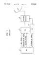
- FIG. 1is a schematic block diagram of a conventional VSAT remote station
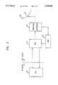
- FIG. 2is a schematic block diagram of a VSAT remote station implemented using a transmit block up-converter according to the invention.
- FIG. 3is a detailed block diagram of a transmit block up-converter according to the invention.
- a voltage signal for output amplification, a transmit intermediate frequency(IF) signal, a reference frequency signal, a switching signal and a level signalare multiplexed in a indoor unit(IDU) 21 and then a multiplexed signal is to be provided to a transmit block up-converter 22 via one transmitting line.
- the voltage signal for output amplificationis converted to a constant-current signal for long distance transmission.
- An received RF signal from an antenna 25is provided t a low noise block clown-converter 23 via an antenna interface 24. Then the RF signal is frequency-converted to the IF signal and amplified in the low noise block down-converter 23, and then the IF signal is provided to the IDU 21 via the transmit block up-converter 22 anti a receiving line.
- the TBUis largely divided into a demultiplexer 32, a frequency up-converting portion 100, a high output amplification portion 200 and an impedance matching and amplification portion 300.
- the multiplexed signal from the IDU 21is divided into a transmit IF signal, a reference frequency signal, a switching signal, a level signal and a constant-current signal in the demultiplexer(DEM) 32.
- the divided constant-current signalis converted into a constant-voltage signal in a current rectifier 60, and then the constant-voltage signal is provided to a high output amplifier 52.
- the reference frequency signalis provided to a reference frequency signal level adjusting circuit 33 which adjusts the level of the signal. Then the reference frequency signal is used for synchronization of a phase locked loop(PLL) 34.
- the output of the PLL 34is applied to a voltage controlled oscillator(VCO) 35.
- the VCO 35generates a frequency signal under control of the PLL 34.
- the frequency signal from the VCO 35is fed-back to the PLL 34 and also is provided to a frequency multiplier(X6) 36.
- the multiplier 36multiplies the frequency signal by 6 times.
- the multiplied frequency signalis provided to the mixer 46 via an amplifier 37 for gain compensation and a band pass filter 38 for suppressing a harmonic wave.
- the level signalis provided to a level detector d2 which detects the level required by the IDU 21.
- the output of the level detector 42is used to control a automatic gain control circuit (AGC) 41.
- the switching signalis applied to a switching signal detector 39 which controls a IF switch 40 depending on a detected request signal such as a signal transmission request or a switch off request.
- a temperature sensor 55detects an internal temperature of the outdoor TBU.
- the output signal of the sensor 55is amplified in a amplifier 54 and then is used to control the gain of an IF attenuator 43. By controlling the gain of an IF attenuator 43, the variation in the amplification factor of the amplification elements in the TBU can be compensated depending on the internal temperature variation.
- the transmit IF signalis provided via the IF AGC 41, the IF switch 40, the IF attenuator 43, the amplifier 44 and the low pass filter 45 to the mixer 46. Then, the IF signal is mixed with the frequency signal provided from the VCO 35 via the multiplier 36, amplifier 37 and the band pass filter 38, and thus is converted into the transmit RF signal. This RF signal is then applied to an isolator 47 which passes a forward signal and blocks a backward signal. The RF signal from the isolator 47 is provided to the high-output amplifier 52 through an amplifier 48, a band pass filter 49, an amplifier 50 and an isolator 51. The high-output amplifier 52 amplifies the RF signal by mean of the constant-voltage signal for high output amplification.
- the amplified RF signalis transmitted via the antenna interface 24 and the antenna 25 to a satellite.
- the received IF signal from the LNB 23is provided to an impedance matching circuit 56 in the impedance matching and amplification portion 300. Then the received IF signal is amplified in an amplifier 57, and then is provided through the receiving signal line to IDU 21. Also, the level signal from the multiplexer 32 is fed-back through an amplifier 59 to the IDU 21. This level signal is used to determine the state of the transmission line.
- the power required to operate internal elements of the TBUis provided through the receiving line and a voltage rectifier 58 to the TBU.
- the deterioration in the transmitting and receiving performance due to loss in the transmission linemay be prevented by providing the AGC circuit and the receiving path.
Landscapes
- Engineering & Computer Science (AREA)
- Computer Networks & Wireless Communication (AREA)
- Signal Processing (AREA)
- Physics & Mathematics (AREA)
- Astronomy & Astrophysics (AREA)
- Aviation & Aerospace Engineering (AREA)
- General Physics & Mathematics (AREA)
- Radio Relay Systems (AREA)
- Transceivers (AREA)
Abstract
Description
1. Field of the Invention
The present invention relates generally to a transmit block up-converter used in a very small aperture terminal remote station(VSAT VRS) for satellite communications and more particularly to a transmit block up-converter for processing a multiplexed signal of a variety of signals which is provided through one transmission line in the VSAT remote station for satellite communications.
2. Description of the Prior Art
Referring to FIG. 1 showing a schematic block diagram of a conventional VSAT remote station, areference numeral 11 denotes a Modem, 12 denotes a transmit block up-converter(TBU), 13 denotes a low noise block down-converter, 14 denotes a antenna interface and 15 denotes an antenna. In the conventional VSAT remote station as shown in FIG. 1, a voltage signal for amplification, a transmit IF signal and a reference frequency signal from theModem 11 are provided to theTBU 12 via a voltage signal line, a IF signal line and a reference frequency signal line respectively. TheTBU 12 frequency-converts the transmit IF signal to tile RF(Radio Frequency) signal, and then amplifies and transmits it via theantenna interface 14 and theantenna 15 to a satellite. The signal received by theantenna 15 is provided to theModem 11 viatile antenna interface 14 and the low noise block down-converter 13. Accordingly, the conventional VSAT remote station has a disadvantage that its constitution is complicated, because a number of signal lines should be used for transmitting and receiving the signals.
Therefore, it is one object of the invention to provide a transmit block up-converter capable of processing a multiplexed signal provided through only one transmitting line.
According to the present invention, it is provided a transmit block up-converting device for processing a multiplexed signal including a transmit IF signal, a reference frequency signal, a switching signal, a level signal and a constant-current signal, which is provided through one transmitting line from an indoor unit in the very small aperture terminal remote station for satellite communications, comprising: a means for demultiplexing said multiplexed signal; a means for frequency up-converting said transmit IF signal from said means for demultiplexing in response to said reference frequency signal, said switching signal and said level signal; a means for amplifying the output signal of said means for frequency up-converting in response to said constant-current signal from said means for demultiplexing; and a means for impedance matching and amplifying an IF signal received from an external unit, and for outputting the impedance matched and amplified signal through one receiving line.
The present invention will be described in more detail with reference to the drawings in which:
FIG. 1 is a schematic block diagram of a conventional VSAT remote station;
FIG. 2 is a schematic block diagram of a VSAT remote station implemented using a transmit block up-converter according to the invention; and
FIG. 3 is a detailed block diagram of a transmit block up-converter according to the invention.
In a VSAT remote station implemented using a transmit block up-converter according to the invention as shown in FIG. 2, a voltage signal for output amplification, a transmit intermediate frequency(IF) signal, a reference frequency signal, a switching signal and a level signal are multiplexed in a indoor unit(IDU) 21 and then a multiplexed signal is to be provided to a transmit block up-converter 22 via one transmitting line. The voltage signal for output amplification is converted to a constant-current signal for long distance transmission. An received RF signal from anantenna 25 is provided t a low noise block clown-converter 23 via anantenna interface 24. Then the RF signal is frequency-converted to the IF signal and amplified in the low noise block down-converter 23, and then the IF signal is provided to the IDU 21 via the transmit block up-converter 22 anti a receiving line.
Now referring to FIG. 3 showing a detailed block diagram of a transmit block up-converter(TBU) according to the invention, the TBU is largely divided into a demultiplexer 32, a frequency up-convertingportion 100, a highoutput amplification portion 200 and an impedance matching andamplification portion 300. The multiplexed signal from the IDU 21 is divided into a transmit IF signal, a reference frequency signal, a switching signal, a level signal and a constant-current signal in the demultiplexer(DEM) 32. The divided constant-current signal is converted into a constant-voltage signal in acurrent rectifier 60, and then the constant-voltage signal is provided to ahigh output amplifier 52. The reference frequency signal is provided to a reference frequency signal level adjusting circuit 33 which adjusts the level of the signal. Then the reference frequency signal is used for synchronization of a phase locked loop(PLL) 34. The output of the PLL 34 is applied to a voltage controlled oscillator(VCO) 35. The VCO 35 generates a frequency signal under control of the PLL 34. The frequency signal from the VCO 35 is fed-back to the PLL 34 and also is provided to a frequency multiplier(X6) 36. The multiplier 36 multiplies the frequency signal by 6 times. The multiplied frequency signal is provided to the mixer 46 via anamplifier 37 for gain compensation and a band pass filter 38 for suppressing a harmonic wave. The level signal is provided to a level detector d2 which detects the level required by the IDU 21. The output of the level detector 42 is used to control a automatic gain control circuit (AGC) 41. The switching signal is applied to aswitching signal detector 39 which controls aIF switch 40 depending on a detected request signal such as a signal transmission request or a switch off request. A temperature sensor 55 detects an internal temperature of the outdoor TBU. The output signal of the sensor 55 is amplified in aamplifier 54 and then is used to control the gain of anIF attenuator 43. By controlling the gain of anIF attenuator 43, the variation in the amplification factor of the amplification elements in the TBU can be compensated depending on the internal temperature variation. The transmit IF signal is provided via the IFAGC 41, the IF switch 40, theIF attenuator 43, the amplifier 44 and thelow pass filter 45 to the mixer 46. Then, the IF signal is mixed with the frequency signal provided from the VCO 35 via the multiplier 36,amplifier 37 and the band pass filter 38, and thus is converted into the transmit RF signal. This RF signal is then applied to anisolator 47 which passes a forward signal and blocks a backward signal. The RF signal from theisolator 47 is provided to the high-output amplifier 52 through an amplifier 48, aband pass filter 49, anamplifier 50 and anisolator 51. The high-output amplifier 52 amplifies the RF signal by mean of the constant-voltage signal for high output amplification. The amplified RF signal is transmitted via theantenna interface 24 and theantenna 25 to a satellite. The received IF signal from the LNB 23 is provided to an impedance matchingcircuit 56 in the impedance matching andamplification portion 300. Then the received IF signal is amplified in anamplifier 57, and then is provided through the receiving signal line to IDU 21. Also, the level signal from the multiplexer 32 is fed-back through an amplifier 59 to the IDU 21. This level signal is used to determine the state of the transmission line. The power required to operate internal elements of the TBU is provided through the receiving line and avoltage rectifier 58 to the TBU.
It may be seen that the present invention provides the following advantages:
(1) the frequency up-conversion and high output amplification functions are performed by one unit.
(2) the construction is simple and cost is reduced, because a variety of signals arc provided through only one transmission line.
(3) it is possible to determine the state of the transmission line by means of the transmit signal feed-back.
(4) the Dower is supplied stably, because the constant-current is used for high output amplification.
(5) the deterioration in the transmitting and receiving performance due to loss in the transmission line may be prevented by providing the AGC circuit and the receiving path.
While the invention has been described in its preferred embodiments, it is to be understood that the words which have been used are words of description rather than limitation and that changes and modifications may be made within the preview of the appended claims without departing from the true scope and spirit of the invention in its broader aspects.
Claims (10)
1. A transmit block up-converting device for processing a multiplexed signal including a transmit IF signal, a reference frequency signal, a switching signal, a level signal and a constant-current signal, which is provided through one transmitting line from an indoor unit in the very small aperture terminal remote station for satellite communications, comprising:
a means for demultiplexing said multiplexed signal;
a means for frequency up-converting said transmit IF signal from said means for demultiplexing in response to said reference frequency signal, said switching signal and said level signal;
a means for amplifying the output signal of said means for frequency up-converting in response to said constant-current signal from said means for demultiplexing; and
a means for impedance matching and amplifying an IF signal received from an external unit, and for outputting the impedance matched and amplified signal through one receiving line.
2. A transmit block up-converting device as claimed in claim 1, further comprising:
a means for amplifying and feeding back said level signal said means for demultiplexing through the receiving line to the indoor unit.
3. A transmit block up-converting device as claimed in claim 2, further comprising:
a means for rectifying a constant-voltage signal provided through the receiving line from the indoor unit.
4. A transmit block up-converting device as claimed in claim 1, further comprising:
a means for sensing the internal temperature of the device, for amplifying a temperature signal, and for providing the amplified temperature signal to said means for frequency up-converting as a control signal.
5. A transmit block up-converting device as claimed in claim 1, wherein said means for frequency up-converting including:
a means for adjusting the level of said reference frequency signal from said means for demultiplexing;
a phase locked loop means connected to the output of said means for adjusting;
a voltage controlled oscillator means, responsive to the output signal of said phase locked loop means, for generating a frequency signal;
a means for multiplying said frequency signal from said voltage controlled oscillator means;
a first amplifier means connected to said means for multiplying; a first band pass filter means connected to said first amplifier means;
a means for detecting the switching signal from said means for demultiplexing;
a means for detecting the level signal from said means for demultiplexing;
a automatic gain control means for controlling the gain of said transmit IF signal from said means for demultiplexing in response to said level signal;
a switch means for controlling the output of said automatic gain control means in response to said switching signal;
a means for attenuating said transmit IF signal in response to said temperature signal from said means for sensing;
a second amplifier means connected to said means for attenuating;
a second band pass filter means connected to said second amplifier means; and
a means for mixing said transmit IF signal from said second band pass filter means with said frequency signal from said first band pass filter means, thereby converting said transmit IF signal into the transmit RF signal.
6. A transmit block up-converting device as claimed in claim 1, wherein said means for amplifying the output signal including:
a means for rectifying said constant-current signal from said means for demultiplexing, thereby converting it into the constant-voltage signal in response to the output signal of said phase locked loop means;
an first isolator means for passing only transmit RF signal and which is connected to said means for mixing;
a first amplifier means connected to said first isolator means;
at first band pass filter means connected to said first amplifier means;
a second amplifier means connected to said first band pass filter means;
a second isolator means connected to said second amplifier means;
a third amplifier means for amplifying the transmit RF signal from said second isolator means in response to said constant-voltage signal from said means for rectifying; and
a third isolator means connected to said third amplifier means.
7. A transmit block up-converting device as claimed in claim 2, further comprising:
a means for rectifying a constant-voltage signal provided through the receiving line from the indoor unit.
8. A transmit block up-converting device as claimed in claim 3, further comprising:
a means for sensing the internal temperature of the device, for amplifying a temperature signal, and for providing the amplified temperature signal to said means for frequency up-converting as a control signal.
9. A transmit block up-converting device as claimed in claim 4, wherein said means for frequency up-converting including:
a means for adjusting the level of said reference frequency signal from said means for demultiplexing;
a phase locked loop means connected to the output of said means for adjusting;
a voltage controlled oscillator means, responsive to the output signal of said phase locked loop means, for generating a frequency signal;
a means for multiplying said frequency signal from said voltage controlled oscillator means;
a first amplifier means connected to said means for multiplying;
a first band pass filter means connected to said first amplifier means;
a means for detecting the switching signal from said means for demultiplexing;
a means for detecting the level signal from said means for demultiplexing;
a automatic gain control means for controlling the gain of said transmit IF signal from said means for demultiplexing in response to said level signal;
a switch means for controlling the output of said automatic gain control means in response to said switching signal;
a means for attenuating said transmit IF signal in response to said temperature signal from said means for sensing;
a second amplifier means connected to said means for attenuating;
a second band pass filter means connected to said second amplifier means; and
a means for mixing said transmit IF signal from said second band pass filter means with said frequency signal from said first band pass filter means, thereby converting said transmit IF signal into the transmit RF signal.
10. A transmit block up-converting device as claimed in claim 5, wherein said means for amplifying the output signal including:
a means for rectifying said constant-current signal from said means for demultiplexing, thereby converting it into the constant-voltage signal in response to the output signal of said phase locked loop means;
an first isolator means for passing only transmit RF signal and which is connected to said means for mixing;
a first amplifier means connected to said first isolator means;
a first band pass filter means connected to said first amplifier means;
a second amplifier means connected to said first band pass filter means;
a second isolator means connected to said second amplifier means;
a third amplifier means for amplifying the transmit RF signal from said second isolator means in response to said constant voltage signal from said means for rectifying; and
a third isolator means connected to said third amplifier means.
Applications Claiming Priority (2)
| Application Number | Priority Date | Filing Date | Title |
|---|---|---|---|
| KR1994-24374 | 1994-09-27 | ||
| KR1019940024374AKR970000660B1 (en) | 1994-09-27 | 1994-09-27 | Satellite communication terminal site |
Publications (1)
| Publication Number | Publication Date |
|---|---|
| US5559809Atrue US5559809A (en) | 1996-09-24 |
Family
ID=19393640
Family Applications (1)
| Application Number | Title | Priority Date | Filing Date |
|---|---|---|---|
| US08/382,395Expired - LifetimeUS5559809A (en) | 1994-09-27 | 1995-02-01 | Transmit block up-converter for very small aperture terminal remote station |
Country Status (3)
| Country | Link |
|---|---|
| US (1) | US5559809A (en) |
| JP (1) | JP2840565B2 (en) |
| KR (1) | KR970000660B1 (en) |
Cited By (42)
| Publication number | Priority date | Publication date | Assignee | Title |
|---|---|---|---|---|
| US5666330A (en)* | 1994-07-21 | 1997-09-09 | Telecom Solutions, Inc. | Disciplined time scale generator for primary reference clocks |
| US5995812A (en)* | 1995-09-01 | 1999-11-30 | Hughes Electronics Corporation | VSAT frequency source using direct digital synthesizer |
| WO2000003494A3 (en)* | 1998-07-09 | 2000-07-13 | Act Wireless | Satellite network terminal |
| US6097765A (en)* | 1995-09-05 | 2000-08-01 | Hughes Electronics Corporation | Method and apparatus for performing digital fractional minimum shift key modulation for a very small aperture terminal |
| WO2001080457A1 (en)* | 2000-04-14 | 2001-10-25 | Hughes Electronics Corporation | A transceiver in a two-way satellite system |
| WO2001080459A1 (en)* | 2000-04-14 | 2001-10-25 | Hughes Electronics Corporation | A transceiver in a two-way satellite system |
| US20010043573A1 (en)* | 2000-04-14 | 2001-11-22 | Frank Kelly | System and method for providing control of a two-way satellite system |
| US20010048669A1 (en)* | 2000-04-14 | 2001-12-06 | Frank Kelly | System interfaces in a two-way satellite system |
| US20020009058A1 (en)* | 2000-04-14 | 2002-01-24 | Frank Kelly | System and method for performing auto-commissioning in a two-way satellite system |
| US6441782B2 (en) | 2000-04-14 | 2002-08-27 | Hughes Electronics Corporation | Method and system of directing an antenna in a two-way satellite system |
| US6614837B1 (en)* | 1998-09-25 | 2003-09-02 | Skyworks Solutions, Inc. | Device system and method for low noise radio frequency transmission |
| US6650869B2 (en) | 2000-04-14 | 2003-11-18 | Hughes Electronics Corporation | System and method for managing return channel bandwidth in a two-way satellite system |
| US20040142668A1 (en)* | 2003-01-10 | 2004-07-22 | David Ge | Systems and methods for transmitting a radio signal |
| US6987741B2 (en) | 2000-04-14 | 2006-01-17 | Hughes Electronics Corporation | System and method for managing bandwidth in a two-way satellite system |
| US20060014501A1 (en)* | 1998-10-21 | 2006-01-19 | Parkervision, Inc. | Applications of universal frequency translation |
| US20060050796A1 (en)* | 2002-09-16 | 2006-03-09 | Philippe Chambelin | Emission device intended to be coupled with a reception device |
| US20060160500A1 (en)* | 2005-01-14 | 2006-07-20 | Xytrans, Inc. | VSAT block up converter (BUC) chip |
| US20060280231A1 (en)* | 1999-03-15 | 2006-12-14 | Parkervision, Inc. | Spread spectrum applications of universal frequency translation |
| US7164661B2 (en) | 2000-04-14 | 2007-01-16 | Hughes Networks Systems, Llc | System and method for providing a two-way satellite system |
| US20070105510A1 (en)* | 1998-10-21 | 2007-05-10 | Parkervision, Inc. | Apparatus and method for communicating an input signal in polar representation |
| US20080204130A1 (en)* | 2007-02-28 | 2008-08-28 | Wheat International Communications Corporation | Oscillator bias injector |
| US20080272441A1 (en)* | 1998-10-21 | 2008-11-06 | Parkervision, Inc. | Method and circuit for down-converting a signal |
| US7460584B2 (en) | 2002-07-18 | 2008-12-02 | Parkervision, Inc. | Networking methods and systems |
| US7463582B2 (en) | 2000-04-14 | 2008-12-09 | Hughes Network Systems, Llc | System and method for scaling a two-way satellite system |
| US7483686B2 (en) | 1999-03-03 | 2009-01-27 | Parkervision, Inc. | Universal platform module and methods and apparatuses relating thereto enabled by universal frequency translation technology |
| US7496342B2 (en) | 2000-04-14 | 2009-02-24 | Parkervision, Inc. | Down-converting electromagnetic signals, including controlled discharge of capacitors |
| US7515896B1 (en) | 1998-10-21 | 2009-04-07 | Parkervision, Inc. | Method and system for down-converting an electromagnetic signal, and transforms for same, and aperture relationships |
| US7539474B2 (en) | 1999-04-16 | 2009-05-26 | Parkervision, Inc. | DC offset, re-radiation, and I/Q solutions using universal frequency translation technology |
| US7546096B2 (en) | 1999-08-23 | 2009-06-09 | Parkervision, Inc. | Frequency up-conversion using a harmonic generation and extraction module |
| US7620378B2 (en)* | 1998-10-21 | 2009-11-17 | Parkervision, Inc. | Method and system for frequency up-conversion with modulation embodiments |
| US7653145B2 (en) | 1999-08-04 | 2010-01-26 | Parkervision, Inc. | Wireless local area network (WLAN) using universal frequency translation technology including multi-phase embodiments and circuit implementations |
| US7653158B2 (en) | 2001-11-09 | 2010-01-26 | Parkervision, Inc. | Gain control in a communication channel |
| US7693230B2 (en) | 1999-04-16 | 2010-04-06 | Parkervision, Inc. | Apparatus and method of differential IQ frequency up-conversion |
| US7724845B2 (en) | 1999-04-16 | 2010-05-25 | Parkervision, Inc. | Method and system for down-converting and electromagnetic signal, and transforms for same |
| US7773688B2 (en) | 1999-04-16 | 2010-08-10 | Parkervision, Inc. | Method, system, and apparatus for balanced frequency up-conversion, including circuitry to directly couple the outputs of multiple transistors |
| US7991815B2 (en) | 2000-11-14 | 2011-08-02 | Parkervision, Inc. | Methods, systems, and computer program products for parallel correlation and applications thereof |
| US8295406B1 (en) | 1999-08-04 | 2012-10-23 | Parkervision, Inc. | Universal platform module for a plurality of communication protocols |
| WO2013039974A1 (en)* | 2011-09-13 | 2013-03-21 | Tracstar Systems, Inc. | Automated satellite interference mitigation |
| US8407061B2 (en) | 2002-07-18 | 2013-03-26 | Parkervision, Inc. | Networking methods and systems |
| WO2017015168A3 (en)* | 2015-07-22 | 2017-03-02 | Hughes Network Systems, Llc | Switchable linear and saturated very small aperture terminal (vsat) modem |
| US9667312B2 (en)* | 2015-01-13 | 2017-05-30 | Hughes Network Systems, Llc | Radio based automatic level control for linear radio calibration |
| CN120493031A (en)* | 2025-07-18 | 2025-08-15 | 陕西华信创宇科技发展有限公司 | A remote management system for frequency converters based on the Internet of Things |
Families Citing this family (2)
| Publication number | Priority date | Publication date | Assignee | Title |
|---|---|---|---|---|
| KR980010094A (en)* | 1996-07-08 | 1998-04-30 | 김광호 | Gas pressure state information detection and display device |
| CN114710373A (en)* | 2022-03-31 | 2022-07-05 | 广州物道水务科技有限公司 | Signal amplification device for Internet of things equipment |
Citations (1)
| Publication number | Priority date | Publication date | Assignee | Title |
|---|---|---|---|---|
| US4748622A (en)* | 1985-08-28 | 1988-05-31 | Kokusai Denshin Denwa Co., Ltd. | Satellite communication system |
Family Cites Families (5)
| Publication number | Priority date | Publication date | Assignee | Title |
|---|---|---|---|---|
| JPH0434596Y2 (en)* | 1985-12-20 | 1992-08-18 | ||
| JPS6378444U (en)* | 1986-11-07 | 1988-05-24 | ||
| JPH0671182B2 (en)* | 1986-11-25 | 1994-09-07 | 三菱電機株式会社 | Frequency conversion amplifier |
| JP2712379B2 (en)* | 1988-09-30 | 1998-02-10 | 日本電気株式会社 | transceiver |
| JP3098540U (en)* | 2003-06-13 | 2004-03-04 | 合名会社大和屋 | Multifunctional chair for children |
- 1994
- 1994-09-27KRKR1019940024374Apatent/KR970000660B1/ennot_activeExpired - Fee Related
- 1995
- 1995-02-01USUS08/382,395patent/US5559809A/ennot_activeExpired - Lifetime
- 1995-02-24JPJP7036637Apatent/JP2840565B2/ennot_activeExpired - Fee Related
Patent Citations (1)
| Publication number | Priority date | Publication date | Assignee | Title |
|---|---|---|---|---|
| US4748622A (en)* | 1985-08-28 | 1988-05-31 | Kokusai Denshin Denwa Co., Ltd. | Satellite communication system |
Cited By (72)
| Publication number | Priority date | Publication date | Assignee | Title |
|---|---|---|---|---|
| US5666330A (en)* | 1994-07-21 | 1997-09-09 | Telecom Solutions, Inc. | Disciplined time scale generator for primary reference clocks |
| US5995812A (en)* | 1995-09-01 | 1999-11-30 | Hughes Electronics Corporation | VSAT frequency source using direct digital synthesizer |
| US6097765A (en)* | 1995-09-05 | 2000-08-01 | Hughes Electronics Corporation | Method and apparatus for performing digital fractional minimum shift key modulation for a very small aperture terminal |
| US6370204B1 (en) | 1995-09-05 | 2002-04-09 | Hughes Electronics Corporation | Method and apparatus for performing digital fractional minimum shift key modulation for a very small aperture terminal |
| WO2000003494A3 (en)* | 1998-07-09 | 2000-07-13 | Act Wireless | Satellite network terminal |
| US6614837B1 (en)* | 1998-09-25 | 2003-09-02 | Skyworks Solutions, Inc. | Device system and method for low noise radio frequency transmission |
| US8233855B2 (en) | 1998-10-21 | 2012-07-31 | Parkervision, Inc. | Up-conversion based on gated information signal |
| US7515896B1 (en) | 1998-10-21 | 2009-04-07 | Parkervision, Inc. | Method and system for down-converting an electromagnetic signal, and transforms for same, and aperture relationships |
| US7620378B2 (en)* | 1998-10-21 | 2009-11-17 | Parkervision, Inc. | Method and system for frequency up-conversion with modulation embodiments |
| US7529522B2 (en) | 1998-10-21 | 2009-05-05 | Parkervision, Inc. | Apparatus and method for communicating an input signal in polar representation |
| US8340618B2 (en) | 1998-10-21 | 2012-12-25 | Parkervision, Inc. | Method and system for down-converting an electromagnetic signal, and transforms for same, and aperture relationships |
| US8190116B2 (en) | 1998-10-21 | 2012-05-29 | Parker Vision, Inc. | Methods and systems for down-converting a signal using a complementary transistor structure |
| US7693502B2 (en) | 1998-10-21 | 2010-04-06 | Parkervision, Inc. | Method and system for down-converting an electromagnetic signal, transforms for same, and aperture relationships |
| US8190108B2 (en) | 1998-10-21 | 2012-05-29 | Parkervision, Inc. | Method and system for frequency up-conversion |
| US8160534B2 (en) | 1998-10-21 | 2012-04-17 | Parkervision, Inc. | Applications of universal frequency translation |
| US20080272441A1 (en)* | 1998-10-21 | 2008-11-06 | Parkervision, Inc. | Method and circuit for down-converting a signal |
| US7826817B2 (en) | 1998-10-21 | 2010-11-02 | Parker Vision, Inc. | Applications of universal frequency translation |
| US20060014501A1 (en)* | 1998-10-21 | 2006-01-19 | Parkervision, Inc. | Applications of universal frequency translation |
| US8019291B2 (en) | 1998-10-21 | 2011-09-13 | Parkervision, Inc. | Method and system for frequency down-conversion and frequency up-conversion |
| US7937059B2 (en) | 1998-10-21 | 2011-05-03 | Parkervision, Inc. | Converting an electromagnetic signal via sub-sampling |
| US7697916B2 (en) | 1998-10-21 | 2010-04-13 | Parkervision, Inc. | Applications of universal frequency translation |
| US7936022B2 (en) | 1998-10-21 | 2011-05-03 | Parkervision, Inc. | Method and circuit for down-converting a signal |
| US20070105510A1 (en)* | 1998-10-21 | 2007-05-10 | Parkervision, Inc. | Apparatus and method for communicating an input signal in polar representation |
| US7865177B2 (en) | 1998-10-21 | 2011-01-04 | Parkervision, Inc. | Method and system for down-converting an electromagnetic signal, and transforms for same, and aperture relationships |
| US7483686B2 (en) | 1999-03-03 | 2009-01-27 | Parkervision, Inc. | Universal platform module and methods and apparatuses relating thereto enabled by universal frequency translation technology |
| US20060280231A1 (en)* | 1999-03-15 | 2006-12-14 | Parkervision, Inc. | Spread spectrum applications of universal frequency translation |
| US7599421B2 (en) | 1999-03-15 | 2009-10-06 | Parkervision, Inc. | Spread spectrum applications of universal frequency translation |
| US7539474B2 (en) | 1999-04-16 | 2009-05-26 | Parkervision, Inc. | DC offset, re-radiation, and I/Q solutions using universal frequency translation technology |
| US8036304B2 (en) | 1999-04-16 | 2011-10-11 | Parkervision, Inc. | Apparatus and method of differential IQ frequency up-conversion |
| US8077797B2 (en) | 1999-04-16 | 2011-12-13 | Parkervision, Inc. | Method, system, and apparatus for balanced frequency up-conversion of a baseband signal |
| US8224281B2 (en) | 1999-04-16 | 2012-07-17 | Parkervision, Inc. | Down-conversion of an electromagnetic signal with feedback control |
| US7894789B2 (en) | 1999-04-16 | 2011-02-22 | Parkervision, Inc. | Down-conversion of an electromagnetic signal with feedback control |
| US7773688B2 (en) | 1999-04-16 | 2010-08-10 | Parkervision, Inc. | Method, system, and apparatus for balanced frequency up-conversion, including circuitry to directly couple the outputs of multiple transistors |
| US7929638B2 (en) | 1999-04-16 | 2011-04-19 | Parkervision, Inc. | Wireless local area network (WLAN) using universal frequency translation technology including multi-phase embodiments |
| US8223898B2 (en) | 1999-04-16 | 2012-07-17 | Parkervision, Inc. | Method and system for down-converting an electromagnetic signal, and transforms for same |
| US8229023B2 (en) | 1999-04-16 | 2012-07-24 | Parkervision, Inc. | Wireless local area network (WLAN) using universal frequency translation technology including multi-phase embodiments |
| US7724845B2 (en) | 1999-04-16 | 2010-05-25 | Parkervision, Inc. | Method and system for down-converting and electromagnetic signal, and transforms for same |
| US7693230B2 (en) | 1999-04-16 | 2010-04-06 | Parkervision, Inc. | Apparatus and method of differential IQ frequency up-conversion |
| US8594228B2 (en) | 1999-04-16 | 2013-11-26 | Parkervision, Inc. | Apparatus and method of differential IQ frequency up-conversion |
| US7653145B2 (en) | 1999-08-04 | 2010-01-26 | Parkervision, Inc. | Wireless local area network (WLAN) using universal frequency translation technology including multi-phase embodiments and circuit implementations |
| US8295406B1 (en) | 1999-08-04 | 2012-10-23 | Parkervision, Inc. | Universal platform module for a plurality of communication protocols |
| US7546096B2 (en) | 1999-08-23 | 2009-06-09 | Parkervision, Inc. | Frequency up-conversion using a harmonic generation and extraction module |
| US6965581B2 (en) | 2000-04-14 | 2005-11-15 | Hughes Electronics Corp. | Transceiver in a two-way satellite system |
| US8295800B2 (en) | 2000-04-14 | 2012-10-23 | Parkervision, Inc. | Apparatus and method for down-converting electromagnetic signals by controlled charging and discharging of a capacitor |
| US7463582B2 (en) | 2000-04-14 | 2008-12-09 | Hughes Network Systems, Llc | System and method for scaling a two-way satellite system |
| WO2001080459A1 (en)* | 2000-04-14 | 2001-10-25 | Hughes Electronics Corporation | A transceiver in a two-way satellite system |
| WO2001080457A1 (en)* | 2000-04-14 | 2001-10-25 | Hughes Electronics Corporation | A transceiver in a two-way satellite system |
| US7164661B2 (en) | 2000-04-14 | 2007-01-16 | Hughes Networks Systems, Llc | System and method for providing a two-way satellite system |
| US7822401B2 (en) | 2000-04-14 | 2010-10-26 | Parkervision, Inc. | Apparatus and method for down-converting electromagnetic signals by controlled charging and discharging of a capacitor |
| US20010048669A1 (en)* | 2000-04-14 | 2001-12-06 | Frank Kelly | System interfaces in a two-way satellite system |
| US20010043574A1 (en)* | 2000-04-14 | 2001-11-22 | Khai Nguyen | Transceiver in a two-way satellite system |
| US6987741B2 (en) | 2000-04-14 | 2006-01-17 | Hughes Electronics Corporation | System and method for managing bandwidth in a two-way satellite system |
| US7496342B2 (en) | 2000-04-14 | 2009-02-24 | Parkervision, Inc. | Down-converting electromagnetic signals, including controlled discharge of capacitors |
| US20010043573A1 (en)* | 2000-04-14 | 2001-11-22 | Frank Kelly | System and method for providing control of a two-way satellite system |
| US20020009058A1 (en)* | 2000-04-14 | 2002-01-24 | Frank Kelly | System and method for performing auto-commissioning in a two-way satellite system |
| US6650869B2 (en) | 2000-04-14 | 2003-11-18 | Hughes Electronics Corporation | System and method for managing return channel bandwidth in a two-way satellite system |
| US6441782B2 (en) | 2000-04-14 | 2002-08-27 | Hughes Electronics Corporation | Method and system of directing an antenna in a two-way satellite system |
| US7991815B2 (en) | 2000-11-14 | 2011-08-02 | Parkervision, Inc. | Methods, systems, and computer program products for parallel correlation and applications thereof |
| US7653158B2 (en) | 2001-11-09 | 2010-01-26 | Parkervision, Inc. | Gain control in a communication channel |
| US8446994B2 (en) | 2001-11-09 | 2013-05-21 | Parkervision, Inc. | Gain control in a communication channel |
| US8160196B2 (en) | 2002-07-18 | 2012-04-17 | Parkervision, Inc. | Networking methods and systems |
| US8407061B2 (en) | 2002-07-18 | 2013-03-26 | Parkervision, Inc. | Networking methods and systems |
| US7460584B2 (en) | 2002-07-18 | 2008-12-02 | Parkervision, Inc. | Networking methods and systems |
| US20060050796A1 (en)* | 2002-09-16 | 2006-03-09 | Philippe Chambelin | Emission device intended to be coupled with a reception device |
| US20040142668A1 (en)* | 2003-01-10 | 2004-07-22 | David Ge | Systems and methods for transmitting a radio signal |
| US20060160500A1 (en)* | 2005-01-14 | 2006-07-20 | Xytrans, Inc. | VSAT block up converter (BUC) chip |
| US20080204130A1 (en)* | 2007-02-28 | 2008-08-28 | Wheat International Communications Corporation | Oscillator bias injector |
| WO2013039974A1 (en)* | 2011-09-13 | 2013-03-21 | Tracstar Systems, Inc. | Automated satellite interference mitigation |
| US8885693B2 (en) | 2011-09-13 | 2014-11-11 | Tracstar Systems, Inc. | Automated satellite interference mitigation |
| US9667312B2 (en)* | 2015-01-13 | 2017-05-30 | Hughes Network Systems, Llc | Radio based automatic level control for linear radio calibration |
| WO2017015168A3 (en)* | 2015-07-22 | 2017-03-02 | Hughes Network Systems, Llc | Switchable linear and saturated very small aperture terminal (vsat) modem |
| CN120493031A (en)* | 2025-07-18 | 2025-08-15 | 陕西华信创宇科技发展有限公司 | A remote management system for frequency converters based on the Internet of Things |
Also Published As
| Publication number | Publication date |
|---|---|
| JPH08111658A (en) | 1996-04-30 |
| JP2840565B2 (en) | 1998-12-24 |
| KR960012773A (en) | 1996-04-20 |
| KR970000660B1 (en) | 1997-01-16 |
Similar Documents
| Publication | Publication Date | Title |
|---|---|---|
| US5559809A (en) | Transmit block up-converter for very small aperture terminal remote station | |
| EP0227393B1 (en) | Radio repeater with spillover measurement | |
| US7395037B2 (en) | Control system for controlling an output signal power level of a wireless transmitter | |
| EP1025656B1 (en) | A transmitter that selectively polarizes a radio wave | |
| US7257369B2 (en) | Repeater with diversity transmission | |
| EP0928072A2 (en) | Transmitter linearization feedback | |
| US7515886B2 (en) | Digital broadcast receiving tuner and receiving device incorporating it | |
| US20020039885A1 (en) | Split repeater | |
| SE507442C2 (en) | High frequency signal amplifier | |
| US5898906A (en) | System and method for implementing a cellular radio transmitter device | |
| US6819173B2 (en) | Method and apparatus for reduction of distortion in a transmitter | |
| US20050227638A1 (en) | Microwave band radio transmission device, microwave band radio reception device, and microwave band radio communication system | |
| CA1194128A (en) | Satellite ground station | |
| AU1857999A (en) | Radio transmitter/receiver | |
| US20040092237A1 (en) | Control system for controlling an output signal power level of a wireless transmitter | |
| JP2004235758A (en) | Millimeter wave transmitting / receiving system, millimeter wave transmitting device, millimeter wave receiving device, and satellite broadcast receiving antenna | |
| US8559896B2 (en) | System and method for radio power level control | |
| JP4074807B2 (en) | Millimeter-wave transmission / reception system, transmission device, and reception device | |
| KR0140677B1 (en) | Phase Control Circuit of Satellite Broadcasting Repeater | |
| KR200185279Y1 (en) | Frequency conversion apparatus in a communication system | |
| JP4695955B2 (en) | Transmission / reception system and reception apparatus | |
| KR100295828B1 (en) | Terminating apparatus for transmitting of transceiver in base station using tower-top form | |
| KR100600969B1 (en) | Mobile communication terminal for reverse power control | |
| KR100340684B1 (en) | Apparatus and method for generating RF multi-tone with service channel space | |
| JPS62188438A (en) | Transmission power control system |
Legal Events
| Date | Code | Title | Description |
|---|---|---|---|
| AS | Assignment | Owner name:ELECTRONICS AND TELECOMMUNICATIONS RESEARCH INSTIT Free format text:ASSIGNMENT OF ASSIGNORS INTEREST;ASSIGNORS:JEON, SOON IK;KIM, JEONG HO;REEL/FRAME:007351/0301 Effective date:19950117 | |
| STCF | Information on status: patent grant | Free format text:PATENTED CASE | |
| FEPP | Fee payment procedure | Free format text:PAYOR NUMBER ASSIGNED (ORIGINAL EVENT CODE: ASPN); ENTITY STATUS OF PATENT OWNER: LARGE ENTITY | |
| FPAY | Fee payment | Year of fee payment:4 | |
| FPAY | Fee payment | Year of fee payment:8 | |
| FPAY | Fee payment | Year of fee payment:12 |