US5559794A - Telecommunication system with selective remote interface assembly and method - Google Patents
Telecommunication system with selective remote interface assembly and methodDownload PDFInfo
- Publication number
- US5559794A US5559794AUS08/118,866US11886693AUS5559794AUS 5559794 AUS5559794 AUS 5559794AUS 11886693 AUS11886693 AUS 11886693AUS 5559794 AUS5559794 AUS 5559794A
- Authority
- US
- United States
- Prior art keywords
- telecommunication system
- central control
- control processor
- single connection
- interface
- Prior art date
- Legal status (The legal status is an assumption and is not a legal conclusion. Google has not performed a legal analysis and makes no representation as to the accuracy of the status listed.)
- Expired - Lifetime
Links
- 238000000034methodMethods0.000titleclaimsdescription22
- 230000002093peripheral effectEffects0.000claimsabstractdescription32
- 230000006854communicationEffects0.000claimsdescription23
- 238000004891communicationMethods0.000claimsdescription23
- 230000008878couplingEffects0.000claims4
- 238000010168coupling processMethods0.000claims4
- 238000005859coupling reactionMethods0.000claims4
- 238000012544monitoring processMethods0.000claims2
- 230000000737periodic effectEffects0.000claims1
- 230000006870functionEffects0.000description10
- 238000012423maintenanceMethods0.000description10
- 238000012546transferMethods0.000description10
- 230000004044responseEffects0.000description5
- 230000005540biological transmissionEffects0.000description4
- 238000004590computer programMethods0.000description4
- 238000011084recoveryMethods0.000description4
- 238000002405diagnostic procedureMethods0.000description2
- 238000010586diagramMethods0.000description2
- 230000009977dual effectEffects0.000description2
- 238000012545processingMethods0.000description2
- 230000011664signalingEffects0.000description2
- 230000003068static effectEffects0.000description2
- 230000001360synchronised effectEffects0.000description2
- 230000007704transitionEffects0.000description2
- 230000007175bidirectional communicationEffects0.000description1
- 239000002131composite materialSubstances0.000description1
- 238000012937correctionMethods0.000description1
- 239000013078crystalSubstances0.000description1
- 238000013500data storageMethods0.000description1
- 238000001514detection methodMethods0.000description1
- 230000003993interactionEffects0.000description1
- 230000007246mechanismEffects0.000description1
- 238000012913prioritisationMethods0.000description1
- 230000008569processEffects0.000description1
Images


Classifications
- H—ELECTRICITY
- H04—ELECTRIC COMMUNICATION TECHNIQUE
- H04Q—SELECTING
- H04Q3/00—Selecting arrangements
- H04Q3/42—Circuit arrangements for indirect selecting controlled by common circuits, e.g. register controller, marker
- H04Q3/54—Circuit arrangements for indirect selecting controlled by common circuits, e.g. register controller, marker in which the logic circuitry controlling the exchange is centralised
- H04Q3/545—Circuit arrangements for indirect selecting controlled by common circuits, e.g. register controller, marker in which the logic circuitry controlling the exchange is centralised using a stored programme
- H04Q3/54541—Circuit arrangements for indirect selecting controlled by common circuits, e.g. register controller, marker in which the logic circuitry controlling the exchange is centralised using a stored programme using multi-processor systems
- H04Q3/5455—Multi-processor, parallelism, distributed systems
Definitions
- the inventionrelates generally to the field of telecommunication systems, and more particularly, to such systems which communicate with a device at a remote location regardless of the operating state of the system.
- Telecommunications systemsemploying a multiplexing multiport switch controlled by a central controlling unit for selectively interconnecting telephonic calls from external telephonic units with internal telephonic units of the telecommunication system are well known. Examples of such telecommunications systems are shown in patent application U.S. Ser. No. 07/770,197 of Jones et al. entitled “Multichannel Telephonic Switching Network With Different Signaling Formats and Connect/PBX Treatment Selectable For Each Channel", filed Oct. 2, 1991; U.S. Pat. No. 5,140,611 of Jones et al. entitled “Pulse Modulated Self-Clocking and Self-Synchronizing Data Transmission and Method for a Telephonic Communication Switching System", issued Aug. 18, 1992; U.S. Pat.
- the object of the inventionis achieved by providing, in a telecommunication system with a distributed processor architecture having a central control processor and a plurality of subprocessor controlled peripheral circuits through which the central control processor receives information and affects a central control of the system, a selective remote interface assembly comprising means for connecting with a single connection modem, means for determining the operating state of the telecommunication system and means responsive to the operating state determining means for selectively obtaining a relatively full featured user interface through the single connection modem connecting means when it is determined that the telecommunication system is in an on-line state and for obtaining a relatively limited user interface through the single connection connecting means when it is determined that the telecommunication system is in an off-line state.
- the object of the inventionis also achieved by provision, in a telecommunication system with a distributed processor architecture having a central control processor and a plurality of subprocessor controlled peripheral circuits through which the central control processor receives information and affects a central control of the system, a method of selectively interfacing with the telecommunication system comprising the steps of (a) determining the operating state of the telecommunication system and (b) selectively obtaining a relatively full featured user interface through the connected single connection modem when it is determined that the system is in an on-line state and selectively obtaining a relatively limited user interface through the single connection modem when it is determined that the system is in an off-line state.
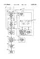
- FIG. 1is a functional block diagram of the preferred embodiment of the telecommunication system of the present invention
- FIG. 2is a functional block diagram of the status and control circuit card of FIG. 1;
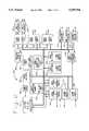
- FIGS. 3A and 3Bform a composite flow chart of the preferred remote communications control software computer program stored in the status and control circuit card of FIGS. 1 and 2 and as reproduced in the printed computer program listing of Appendix A attached to the back of this application.
- the telecommunication system 10is shown having a multiport switch 12 controlled by a central control processor unit 14 for interconnecting internal telephonic units 16 with telephonic calls received from external telephonic units 18 through the external telephonic switching network 20.
- the telecommunications system 10has a distributed processor architecture with many subprocessor controlled peripheral circuits 13 performing specialized functions and transmitting information to the central control processor 14 of the multiport switch 12.
- the selective remote interface assembly 11 of the present inventionincludes the subprocessor controlled peripheral circuits: the status and control circuit card 24 and the peripheral data interface circuit card 22.
- the status and control (STC) card 24is one subprocessor controlled peripheral control circuit coupled to the central control processor 14 which contains the interfaces between the multiport switch and a remote maintenance device 26.
- the peripheral data interface (PDI) circuit card 22is another subprocessor controlled peripheral circuit coupled with the central control processor 14 and the status and control circuit 24 which provides an interface between line printers, data links and cathode ray tube terminals (not shown) of the system 10 and the central control circuit unit 14.
- the remote maintenance device 26is a window based workstation with a terminal which provides an intelligent interface between the user of the device and the multiport switch 12.
- the user at the remote deviceenters various commands to perform diagnostic and maintenance functions on the switch 12 when the telecommunication system is in the off-line operating state.
- the remote device 26is connected to an external modem 28 which converts digital signals received from the remote device to analog signals transmitted through the external telephonic switching network 20 and vice-versa.
- the signals from the remote device 26 via the external modem 28 and the external telephonic switching network 20are transmitted to a single connection modem 30 of the telecommunication system 10.
- the demodulator of the single connection modem 30converts the analog signal received through the external telephonic network 20 into a digital signal which is transmitted using a standard RS-232 interface to a remote port 32 at the status and control circuit card 24.
- the single connection modem 30further converts a digital signal received from the STC card 24 to an analog signal for transmission through the external telephonic switching network 20 and eventually to the remote device 26.
- the single connection modem 30interfaces with a remote port 32 of the STC card 24 through a serial 31 and serially communicates using a standard RS-232 protocol.
- the remote device 26accesses information from the multiport switch 12 regardless of the operating state (i.e on-line state or off-line state) of the system 10. If the telecommunication system 10 is in an off-line state the remote device 26 communicates to the central control processor or central control unit 14 only through the status and control card 24.
- the STC circuit 24provides only relatively limited user interface capability for performing diagnostic tests and maintenance functions on the multiport switch 12 of the system 10.
- the user interface obtained while the system 10 is off-lineis limited to the status and control card 24 restarting of the switch 12 via the central control unit 14 to return the system to the on-line operating status.
- a relatively full featured user interfaceis available to the user at the remote device 26 via the peripheral data interface (PDI) circuit card 22.
- An existing PDI port 34is coupled via a serial cable 36 to an existing STC port 38 on the STC card 24. Data transmissions between the existing PDI port 34 of the PDI card 22 and the existing STC port 38 coupled across the serial cable 36 preferably follow a standard RS-232 communications protocol.
- the status and control card 24adapts to the proper user interface (i.e. limited user capabilities, or full featured over capabilities) based upon the operating state of the multiport switch.
- the remote communications control task software running on the STC card 24receives data at the remote port 32 of the STC and responds by providing a minimal user interface and capabilities at the remote device 26.
- the STC card 24bypasses the PDI card and directly communicates with the central control processor 14.
- a serial connectionis established between the serial cable 31 connected to the STC 24 and the central control processor 14 when the system 10 is in an off-line state.
- the remote communications control taskis removed from the data flow by executing a PDI port interrupt handler and allowing the remote port 32 interrupt handler to transfer the incoming data from the remote device 26 directly to the STC port 38 connected to the PDI port 34 of the PDI 22.
- the remote port handleris an interrupt routine which runs on the STC card 24 and functions to transfer data from the remote port 32 of the STC.
- the PDI port interrupt handleris an interrupt routine which runs on the STC card 24 and services the STC port 38 connected to the PDI port 34 of the PDI card 22 by the serial cable 36.
- the PDI port interrupt handlertransfers outgoing data to the remote device 26 directly to the remote port 32.
- This pass-through mode occurring when the telecommunication system 10 is on-line,allows bidirectional communication between the remote device 26 and the full featured interface to the multiport switch of the existing STC port 38 coupled to the PDI circuit 22.
- the STCselectively obtains a relatively full featured user interface through the serial cable 31 connected to the single connection modem 30 when it determines that the system 10 is on-line.
- the STC 24obtains a relatively limited user interface through the serial cable 31 connected to the single connection modem when the STC determines that the telecommunication system 10 is off-line.
- a keep-alive message or on-line signalis periodically sent from the central control processor 14 of the multiport switch 12 to the STC circuit 24 every fifteen seconds to inform the STC circuit of the operating state of the telecommunication system 10.
- the STC circuit 24monitors the operating state of the system 10 through the receipt of the on-line signal sent from the central control processor 14. Failure to receive a keep-alive message at the STC circuit 24 after fifteen seconds indicates that the telecommunication system 10 is in the off-line operating state.
- the status and control card 24determines the operating state of the system 10 based on the receipt of the keep alive messages from the central control unit 14 of the switch 12.
- the pass through mode of the STC card 24is discontinued by disabling the PDI port interrupt handler and allowing the STC card to intercept and to respond to the incoming data received from the remote device 26. If the telecommunication system 10 transitions from the off-line state to the on-line state, the user at the remote device 26 enters an appropriate command to re-establish the pass through mode at the STC card 26, thereby enabling the user at the remote device to have full featured capabilities.
- the remote communications control task software running on the STC circuit 24allows the remote device 26 to access information through a serial cable 31 connected with the standard single connection modem 30.
- the pass through feature of the STC card 24eliminates the costly disadvantages as seen in the known systems of needing a sophisticated software controlled multiplexing modem in order for a remote device to gain access to a plurality of peripheral subprocessor controlled circuit cards in a telecommunication system having a distributed architecture.
- the standard single connection modem 30 utilized in the telecommunication system 10 of the present inventionis a Universal Data System V.3224/V.3225 type model.
- the central control processor unit 14is the primary processing element of the multiplexing multiport switch 12.
- the central control processor 14receives information from the peripheral subprocessor controlled circuits 22 and 24 and affects the central control of the system 10.
- the central control processor unit 14contains a 68030 microprocessor and 6881 arithmetic co-processor operating at a thirty-three MHz clock rate. Additionally, the central control processor is equipped with five hundred twelve kbytes of SRAM and two hundred fifty-six kbytes of EPROM.
- the central control unit 14controls maintenance as an essential element in the telecommunication system 10 switching function during fault conditions.
- the selective remote interface assembly 11 of the present inventioncan be implemented in numerous types and sizes of telecommunication systems employing a computer controlled multiport switch, it is preferably employed in a telecommunication system of the type shown in patent application U.S. Ser. No. 07/770,197 of Jones et al. entitled “Multichannel Telephonic Switching Network With Different Signaling Formats and Connect/PBX Treatment Selectable For Each Channel", filed Oct. 2, 1991; U.S. Pat. No. 5,140,611 of Jones et al. entitled “Pulse Modulated Self-Clocking and Self-Synchronizing Data Transmission and Method for a Telephonic Communication Switching System", issued Aug. 18, 1992 and U.S. Pat. No 5,127,004 of Lenihan et al. entitled “Tone and Announcement Message Code Generator for a Telephonic Switching System and Method", issued Jun. 30, 1992.
- the Peripheral Data Interface (PDI) Card 22has a 68000 microprocessor operating at a ten MHz clock rate.
- the clock of the PDI 22is equipped with two Mbytes of on-board DRAM and sixty-four Kbytes of EPROM.
- the PDI 22supports eight serial data ports, each of which may be configured for RS232C, RS423, RS422 or RS485 operation. X.25 synchronous ports up to one MHz (external clocks) as well as asynchronous ports up to 19.2 Kbaud (internal clocks) are supported.
- RS232CRS232C
- RS423, RS422 or RS485 operationX.25 synchronous ports up to one MHz (external clocks) as well as asynchronous ports up to 19.2 Kbaud (internal clocks) are supported.
- X.25 synchronous ports up to one MHz (external clocks)as well as asynchronous ports up to 19.2 Kbaud (
- the Status and Control (STC) card 24provides functions for remote interfacing, a local interfacing, alarm signal gathering/interpretation/control, and interfacing with central control unit 14 as part of the system control and fault recovery structure.
- the STC 24contains a 68000 microprocessor operating at a ten MHz clock rate.
- the STC 24is equipped with two Mbytes on-board DRAM 48, one hundred twenty-eight Kbytes of EPROM 52 and eight Kbytes of battery-backed SRAM 54.
- the STC card 24is shown with a 68000 microprocessor 44 operating from a ten MHz clock 46 providing the intelligence for the STC.
- a two Megabyte Dynamic Random Access Memory (DRAM) 48 device array(one M ⁇ sixteen bits+two parity bits) provides memory space for down-loaded code, data storage and scratch space.
- the DRAM 48 read/write cycle timeis four hundred nanoseconds.
- DRAM 48 integrityis checked by parity bits over byte boundaries with a DRAM controller 49 with parity check logic.
- Memory access protection of the DRAM 48is provided by a two hundred fifty-six ⁇ four bit static random access memory (SRAM) 50 and allows write, fetch and supervisor protection capability over eight Kbyte blocks of the DRAM for software diagnostic purposes.
- SRAMstatic random access memory
- EPROM 52erasable programmable read only memory
- the read cycle time of the EPROM 52is five hundred nanoseconds.
- the software protocols for the remote communications control software operationare resident in the EPROM 52.
- An eight K ⁇ sixteen bit static RAM 54 having one hours of power back-upis provided as nonvolatile storage space for system parameters and diagnostic information. Timing of the various devices of the status and control circuit card 24 is provided by the baud rate and internal clocks 55 in the system.
- the 68681 DUART 56provides asynchronous serial ports with TTL signal-level line drivers/receivers for interface links to the central control processor also called the bus maintenance unit (BMU) 14, FIG. 1 and to an alternate copy STC interface 62.
- BMUbus maintenance unit
- An STC to STC interface link and two STC to BMU linksare part of the redundancy and fault recovery mechanism of the architecture in fully redundant systems.
- the DUARTs 56provide two central control unit links or BMU links 60 allowing access into the central control processors 14, FIG. 1, for the remote external maintenance device 26, FIG. 1.
- the 68562 DUART device 58supports two RS232C ports with one to a local terminal and the other to a standard single connection modem 30. These devices support a variety of protocols, both asynchronous and synchronous, including X.25, BX.25 and other SDLC/HDLC type formats. A port is provided for linking over the standard single connection modem 30, FIG. 1, to the remote device 26.
- Central control processor interfaces 60are provided to the central control processor unit or BMU 14 as part of the fault recovery philosophy of the telecommunication system 10 distributed processor architecture.
- the central control processor interface 60consists of a standard serial interface with several control leads.
- the STC card 24is the telecommunication system 10 alarm gatherer/interpreter/controller.
- the alarm input circuits 68 and alarm output circuits 70 of the STC 24gather alarms from the remote device 26 and reports them through software interaction through relay contact outputs.
- the STC 24has provision for up to seventy-six separate loop closure inputs for alarm detection.
- Two 68901 multifunction peripherals 72 and 74each contain four eight bit timers, an interrupt prioritization/control function and a serial port.
- One 68901 multifunction peripheral 72is fed by a 3.6864 MHz clock, from the internal clock circuit 55 and is programmed with one its timers acting as baud rate generator for its serial port.
- the other 68901 multifunction peripheral 74is fed by a 2.5 MHz clock from the internal clock circuit 55.
- one of the timers of the multifunction peripheral 74is programmed by software to provide a ten millisecond clock source for use as a relative real-time reference and for use as a ten millisecond interrupt source for the microprocessor 44.
- a real-time clock device 64implemented on the STC 24 is used for time-tracking system outages and other short term timing functions.
- the clock 64is driven by a signal derived from an onboard crystal oscillator.
- the real time clock device 64has up to four hours of power backup protection. Sixty-four bytes of memory are also provided within the clock 64 for storage of various system parameters.
- a power-on reset circuit controller 66is provided to ensure a clean start-up condition.
- the reset logic of the power-on reset circuit 66responds to a signal from the central control circuit 14, FIG. 1, over a reset maintenance interface 78 to the STC 24.
- the on-board microprocessor 44also initiates a software directed board level reset to attempt correction of a nonresponsive condition.
- the method of the inventioncan be practiced with any other telecommunication systems with a distributed processor architecture having a central control processor and a plurality of subprocessor controlled peripheral circuits through which the central control processor receives information and affects a central control of the system.
- the preferred method of practicing the inventioncomprises the steps of (1) determining the operating state of the telecommunication system and (2) selectively obtaining a relatively full featured user interface through a single connection modem connecting means, when it is determined that the system is in an on-line state and selectively obtain a relatively limited user interface through the single connection modem connecting means, when it is determined that the telecommunication system is in an off-line state.
- status and control circuit card 24contains the remote communications control task computer program to achieve the various functions of the invention described above.
- the listing of the programis attached in Appendix A.
- FIGS. 3A and 3Billustrate a flow chart for the preferred computer program in the Status and Control circuit card, FIG. 2, and as reproduced in the printed computer program listing of Appendix A attached to the back of this application.
- steps 100-106illustrate the initial power-up of the STC circuit card 24.
- the STC card 24, FIG. 1is initialized by applying external power to the circuit card.
- the communication stateis set to the remote state or the disable pass through mode.
- charactersare sent one at a time from the remote device 26, FIG. 1, to the STC circuit 24.
- the remote statethere is no protocol for the sending of the data entered at the remote device 26 appearing on the terminal screen of the remote device.
- the interrupt handler for the remote port 32, FIG. 1is installed.
- the remote port interrupt handlerpreforms the functional processing of the information received from an interrupt on the remote port 32 of the STC card 24.
- the PDI port interrupt handleris installed to process the information received at the STC port 38 connected to the PDI card 22, FIG. 1. Once the PDI port interrupt handler is installed, the remote connection control proceeds to step 132, FIG. 3B.
- Steps 108-116, FIG. 3Aillustrate the software processing for the reading of a remote port 32, FIG. 1, interrupt.
- step 108, FIG. 3Aan interrupt is received from the remote device 26, FIG. 1, at the remote port 32 of the STC circuit 24.
- step 110, FIG. 3Athe microprocessor 44, FIG. 2, of the STC circuit 24 determines if it, FIG. 1, is in the pass-through mode thereby indicating that the system 10 is on-line. If the STC circuit 24 is not in the pass-through mode, then in step 112, FIG. 3A, the data sent from the remote device 26 is copied into a generic buffer at the DPRAM 48, FIG. 2 of the STC card 24.
- the remote port interrupt routineproceeds to step 132. If the switch 12, FIG. 1, is in the pass-through mode, then in step 114, FIG. 3A, the data received at the remote port 32, FIG. 1, is copied into a memory buffer at the DUART 56, FIG. 2, of the STC circuit 24. In step 116, FIG. 3A, the data is sent to the existing STC port 38, FIG. 1, connected to the PDI circuit 22 across the serial cable 36.
- Steps 118-126illustrate the PDI port interrupt routine of the remote communications control task software.
- the STC circuit 24, FIG. 1receives an interrupt from the PDI 22 at the existing STC port 38.
- the microprocessor 40, FIG. 2, of the STC card 24, FIG. 1determines if it is in the pass-through mode by reading the communication state of the card. If the STC card 24 is not in the pass-through mode, then the data received at the existing STC port 38 is copied into the generic buffer of the DRAM 48, FIG. 2, of the STC circuit 24. If the STC 24, FIG. 1, is in the pass-through mode, then in step 124, FIG. 3A, the data received at the existing STC port 38, FIG. 1, is copied into the DUSCC buffer 58 of the STC card circuit 24. In step 126, FIG. 3A, the data is sent to the remote port 32 of the status and control circuit 24.
- the remote communications control taskis initiated in response to the telecommunication system 10, FIG. 1, going off-line. Furthermore, the remote communications control task is also initiated in response to the central control circuit 14, FIG. 1, of the switch 12 requesting a file transfer in step 130.
- a file transfer requestoccurs only when the STC 24 is in the pass-through mode.
- the central control circuit 16transfers information to the user at the remote device 26 upon the occurrence of predetermined conditions. Preferably, the information in a transferred file informs the user at the remote device 26 of technical problems within the telecommunication system 10 in order for the user to perform maintenance operations on the system from a remote location.
- the conditions discussed in steps 128 and 130, FIG. 3Boperate independently of the operating state of the telecommunication system 10, FIG. 1.
- step 132, FIG. 3Bthe microprocessor 44, FIG. 2, of the STC circuit card 24 determines if there is a modem 30, FIG. 1, connection to the remote device 26. If there is no modem connection, then the STC 24 continues to dial out until a connection is established at the modem 30. If there is a connection between the modem and the remote device 26, then in step 136, FIG. 3B, the microprocessor 44, FIG. 2, of the STC circuit 24 determines the mode of communication for the STC. If the STC 24 is in the pass-through mode, then in step 138, FIG. 3B, the STC circuit card 24, FIG. 1, repeatedly sends a disable pass through mode message to the remote device 26 until the remote device returns the message back to the STC circuit card 24. The return of the disable pass through mode message indicates that the remote device 26 10 is in the pass-through mode. In step 140, FIG. 3B, the STC circuit card 24, FIG. 1, changes to the disable pass through mode.
- step 142the STC circuit 24 determines if a received request is for a file transfer. If the request is a file transfer request, then in step 144, FIG. 3B, the STC circuit 24, FIG. 1, repeatedly sends a pass through mode message until the remote device 26 returns the pass-through message to the STC. In step 146, FIG. 3B, the STC circuit 24, FIG.
- step 148FIG. 3B
- the pass-through modecontinues at the STC circuit 24, FIG. 1, until the central control unit 14 of the multiport switch 12 completes the file transfer.
- step 149FIG. 3B
- the STC cardswitches back to its original mode prior to step 132.
- step 142the STC circuit, FIG. 1, determines that the received request is not a file transfer request
- step 143FIG. 3B
- the STC circuitdetermines if the received request is a request by the user at the remote device 26 to go to the pass-through mode. If the received request is a request to go to the pass-through mode, then the STC 24 goes to step 144, FIG. 3B, to repeatedly send a pass-through mode message to the remote device 26.
- the STC circuit, FIG. 1then proceeds to execute steps 144-149. If the received request is not a request to go to the pass through mode, then in step 150, FIG. 3B, the STC circuit 24, FIG. 1, displays a user menu at the remote device 26 and waits for a user input at the remote device. In step 152 the modem 30 connection is dropped after fifteen minutes of inactivity at the remote device.
Landscapes
- Engineering & Computer Science (AREA)
- Computer Networks & Wireless Communication (AREA)
- Telephonic Communication Services (AREA)
Abstract
Description
Claims (23)
Priority Applications (1)
| Application Number | Priority Date | Filing Date | Title |
|---|---|---|---|
| US08/118,866US5559794A (en) | 1993-09-09 | 1993-09-09 | Telecommunication system with selective remote interface assembly and method |
Applications Claiming Priority (1)
| Application Number | Priority Date | Filing Date | Title |
|---|---|---|---|
| US08/118,866US5559794A (en) | 1993-09-09 | 1993-09-09 | Telecommunication system with selective remote interface assembly and method |
Publications (1)
| Publication Number | Publication Date |
|---|---|
| US5559794Atrue US5559794A (en) | 1996-09-24 |
Family
ID=22381225
Family Applications (1)
| Application Number | Title | Priority Date | Filing Date |
|---|---|---|---|
| US08/118,866Expired - LifetimeUS5559794A (en) | 1993-09-09 | 1993-09-09 | Telecommunication system with selective remote interface assembly and method |
Country Status (1)
| Country | Link |
|---|---|
| US (1) | US5559794A (en) |
Cited By (41)
| Publication number | Priority date | Publication date | Assignee | Title |
|---|---|---|---|---|
| US6443839B2 (en) | 1999-10-06 | 2002-09-03 | Igt | Standard peripheral communications |
| US6480587B1 (en) | 1996-12-16 | 2002-11-12 | Sanjay K. Rao | Intelligent keyboard system |
| US6532494B1 (en)* | 1999-05-28 | 2003-03-11 | Oracle International Corporation | Closed-loop node membership monitor for network clusters |
| US20030054880A1 (en)* | 1999-10-06 | 2003-03-20 | Igt | USB device protocol for a gaming machine |
| US6614802B1 (en)* | 1999-01-18 | 2003-09-02 | Lucent Technologies Inc. | Telecommunication network with remotely controllable, line multi-interface and telecommunication method |
| US20030178774A1 (en)* | 2002-03-19 | 2003-09-25 | Marcilio Fernando Mauro | Card game |
| US6678728B1 (en)* | 1999-12-03 | 2004-01-13 | 3Com Corporation | Method and apparatus for automatically loading device status information into a network device |
| US6682423B2 (en) | 2001-04-19 | 2004-01-27 | Igt | Open architecture communications in a gaming network |
| US6722985B2 (en) | 2001-04-19 | 2004-04-20 | Igt | Universal player tracking system |
| US20040192439A1 (en)* | 2003-03-26 | 2004-09-30 | Miroslaw Kula | Electronic delivery of gaming tickets |
| US20040254006A1 (en)* | 1999-10-06 | 2004-12-16 | Igt | USB software architecture in a gaming machine |
| US20040254013A1 (en)* | 1999-10-06 | 2004-12-16 | Igt | Download procedures for peripheral devices |
| US20040254014A1 (en)* | 1999-10-06 | 2004-12-16 | Igt | Protocols and standards for USB peripheral communications |
| US20050021277A1 (en)* | 2003-05-13 | 2005-01-27 | Fan-Tien Cheng | Generic embedded device and mechanism thereof for various intelligent-maintenance applications |
| US6871222B1 (en) | 1999-05-28 | 2005-03-22 | Oracle International Corporation | Quorumless cluster using disk-based messaging |
| US6914888B1 (en)* | 1998-02-25 | 2005-07-05 | Rohde & Schwarz Gmbh & Co. Kg | Radio device with remote control |
| US7020695B1 (en) | 1999-05-28 | 2006-03-28 | Oracle International Corporation | Using a cluster-wide shared repository to provide the latest consistent definition of the cluster (avoiding the partition-in time problem) |
| US7076783B1 (en) | 1999-05-28 | 2006-07-11 | Oracle International Corporation | Providing figure of merit vote from application executing on a partitioned cluster |
| US20060205514A1 (en)* | 2005-03-09 | 2006-09-14 | Igt | MRAM as critical event storage for powered down gaming machines |
| US20060205513A1 (en)* | 2005-03-09 | 2006-09-14 | Igt | MRAM as nonvolatile safe storage for power hit and ESD tolerance in gaming machines |
| US20060205515A1 (en)* | 2005-03-09 | 2006-09-14 | Igt | Magnetoresistive memory units as read only memory devices in gaming machines |
| US20060262907A1 (en)* | 2005-05-19 | 2006-11-23 | Sbc Knowledge Ventures Lp | Switching public safety answering points between central offices |
| US20070026894A1 (en)* | 2005-07-29 | 2007-02-01 | Peter Zatloukal | Multiple processor communication circuit cards and communication devices that employ such cards |
| US20080129465A1 (en)* | 1996-12-16 | 2008-06-05 | Rao Raman K | System for seamless and secure networking of implantable medical devices, electronic patch devices and wearable devices |
| US20080139907A1 (en)* | 1996-12-16 | 2008-06-12 | Rao Raman K | Intelligent personal health management appliances for the measurement and monitoring of health factors and controlled delivery of drugs |
| US20080217645A1 (en)* | 2007-03-09 | 2008-09-11 | Adam William Saxler | Thick nitride semiconductor structures with interlayer structures and methods of fabricating thick nitride semiconductor structures |
| US7837556B2 (en) | 2001-09-28 | 2010-11-23 | Igt | Decoupling of the graphical presentation of a game from the presentation logic |
| US20110059777A1 (en)* | 1999-06-04 | 2011-03-10 | Ip Holdings, Inc. | Reconfigurable mobile device interfaces supporting authenticated high quality video, audio, tv and multimedia services |
| US7929950B1 (en) | 1996-12-16 | 2011-04-19 | Ip Holdings, Inc. | Dynamically configurable IP based wireless device and wireless networks |
| US7931533B2 (en) | 2001-09-28 | 2011-04-26 | Igt | Game development architecture that decouples the game logic from the graphics logics |
| US20110161279A1 (en)* | 1996-12-16 | 2011-06-30 | Ip Holdings, Inc. | Matching network system for mobile devices |
| US8357034B2 (en) | 2007-11-08 | 2013-01-22 | Igt | Gaming system and method providing third party promotions |
| US8506378B2 (en) | 2011-09-21 | 2013-08-13 | Igt | Gaming system, gaming device, and method providing advertising messages to players based on a determination of a positive winning gaming session |
| US8708828B2 (en) | 2001-09-28 | 2014-04-29 | Igt | Pluggable modular gaming modifiers and configuration templates for gaming environments |
| US8715177B2 (en) | 2000-10-06 | 2014-05-06 | Ip Holdings, Inc. | Intelligent drug delivery appliance |
| US8965460B1 (en) | 2004-01-30 | 2015-02-24 | Ip Holdings, Inc. | Image and augmented reality based networks using mobile devices and intelligent electronic glasses |
| US9300645B1 (en) | 2013-03-14 | 2016-03-29 | Ip Holdings, Inc. | Mobile IO input and output for smartphones, tablet, and wireless devices including touch screen, voice, pen, and gestures |
| US9449091B1 (en) | 2003-08-20 | 2016-09-20 | Ip Holdings, Inc. | Professional and employee social networks and social media systems |
| US10142496B1 (en) | 2013-01-26 | 2018-11-27 | Ip Holdings, Inc. | Mobile device image capture and image modification including filters, superimposing and geofenced comments in augmented reality |
| US10140514B1 (en) | 2004-01-30 | 2018-11-27 | Ip Holdings, Inc. | Capturing and sharing images with mobile device users including for a limited duration of time |
| US11455799B2 (en) | 2004-01-30 | 2022-09-27 | Airspace Reality | Image networks for mobile communication |
Citations (8)
| Publication number | Priority date | Publication date | Assignee | Title |
|---|---|---|---|---|
| US5347512A (en)* | 1993-09-17 | 1994-09-13 | Rockwell International Corporation | Telecommunication system with delay data buffer and method |
| US5353343A (en)* | 1992-04-30 | 1994-10-04 | Rockwell International Corporation | Telephonic switching system with a user controlled data memory access system and method |
| US5365581A (en)* | 1992-06-25 | 1994-11-15 | Rockwell International Corporation | Telephonic switching system with automatic port assignment capability and method |
| US5384841A (en)* | 1993-10-27 | 1995-01-24 | Rockwell International Corporation | Automatic call distribution network with call overload system and method |
| US5386412A (en)* | 1993-05-11 | 1995-01-31 | Park; Jung S. | Telecommunication system protocol for asynchronous data communication between multiport switch control processor and information support personal computer terminal |
| US5392329A (en)* | 1992-10-27 | 1995-02-21 | Rockwell International Corporation | Automatic call distribution system with emergency recording system and method |
| US5400327A (en)* | 1993-09-30 | 1995-03-21 | Rockwell International Corporation | Automatic call distributor with wireless connection with remote unit and method |
| US5452348A (en)* | 1993-02-12 | 1995-09-19 | Adams; David J. | Automatic call distribution system with emergency conferencing and method |
- 1993
- 1993-09-09USUS08/118,866patent/US5559794A/ennot_activeExpired - Lifetime
Patent Citations (8)
| Publication number | Priority date | Publication date | Assignee | Title |
|---|---|---|---|---|
| US5353343A (en)* | 1992-04-30 | 1994-10-04 | Rockwell International Corporation | Telephonic switching system with a user controlled data memory access system and method |
| US5365581A (en)* | 1992-06-25 | 1994-11-15 | Rockwell International Corporation | Telephonic switching system with automatic port assignment capability and method |
| US5392329A (en)* | 1992-10-27 | 1995-02-21 | Rockwell International Corporation | Automatic call distribution system with emergency recording system and method |
| US5452348A (en)* | 1993-02-12 | 1995-09-19 | Adams; David J. | Automatic call distribution system with emergency conferencing and method |
| US5386412A (en)* | 1993-05-11 | 1995-01-31 | Park; Jung S. | Telecommunication system protocol for asynchronous data communication between multiport switch control processor and information support personal computer terminal |
| US5347512A (en)* | 1993-09-17 | 1994-09-13 | Rockwell International Corporation | Telecommunication system with delay data buffer and method |
| US5400327A (en)* | 1993-09-30 | 1995-03-21 | Rockwell International Corporation | Automatic call distributor with wireless connection with remote unit and method |
| US5384841A (en)* | 1993-10-27 | 1995-01-24 | Rockwell International Corporation | Automatic call distribution network with call overload system and method |
Cited By (103)
| Publication number | Priority date | Publication date | Assignee | Title |
|---|---|---|---|---|
| US8818451B2 (en) | 1996-12-16 | 2014-08-26 | Ip Holdings, Inc. | Image networks for mobile communication |
| US8447289B2 (en) | 1996-12-16 | 2013-05-21 | Ip Holdings, Inc. | Dynamically configurable wireless device and server communication system |
| US7929950B1 (en) | 1996-12-16 | 2011-04-19 | Ip Holdings, Inc. | Dynamically configurable IP based wireless device and wireless networks |
| US10530907B1 (en) | 1996-12-16 | 2020-01-07 | Rekha K Rao | Wireless device communication system |
| US6480587B1 (en) | 1996-12-16 | 2002-11-12 | Sanjay K. Rao | Intelligent keyboard system |
| US10469644B1 (en) | 1996-12-16 | 2019-11-05 | Raman Kaliputnam Rao | Configurable mobile device for authenticated communication, voice recognition, and touch sensitive input |
| US9094390B1 (en) | 1996-12-16 | 2015-07-28 | Ip Holdings, Inc. | Social media system with public and private networks and profiles |
| US9614943B1 (en) | 1996-12-16 | 2017-04-04 | Rekha K. Rao | System to interface internet protocol (IP) based wireless devices with subtasks and channels |
| US9319075B1 (en) | 1996-12-16 | 2016-04-19 | Ip Holdings, Inc. | Wireless devices with transmission control and multiple internet protocol (IP) based paths of communication |
| US9301237B1 (en) | 1996-12-16 | 2016-03-29 | Ip Holdings, Inc. | Server control and defined software networking |
| US20110161279A1 (en)* | 1996-12-16 | 2011-06-30 | Ip Holdings, Inc. | Matching network system for mobile devices |
| US9084291B1 (en) | 1996-12-16 | 2015-07-14 | Ip Holdings, Inc. | Interfacing internet protocol-based wireless devices with networks |
| US9083763B2 (en) | 1996-12-16 | 2015-07-14 | Ip Holdings, Inc. | Social networking system |
| US9049119B2 (en) | 1996-12-16 | 2015-06-02 | Ip Holdings, Inc. | Dynamically configurable mobile device and cellular phones with functions |
| US9019946B1 (en) | 1996-12-16 | 2015-04-28 | Ip Holdings, Inc. | Wireless and cellular voice and data transmission with multiple paths of communication |
| US8982863B1 (en) | 1996-12-16 | 2015-03-17 | Ip Holdings, Inc. | Controller and server system for networking |
| US8964712B1 (en) | 1996-12-16 | 2015-02-24 | Ip Holdings, Inc. | Wireless connectivity system for adapter, mobile device and non-wireless device |
| US6865261B1 (en) | 1996-12-16 | 2005-03-08 | Raman K. Rao | Method for providing gastronomic information and instruction with an internet server using mobile communications or computing devices and intelligent appliances |
| US9191083B1 (en) | 1996-12-16 | 2015-11-17 | Ip Holdings, Inc. | Wireless device with multichannel data transfer |
| US6882859B1 (en) | 1996-12-16 | 2005-04-19 | Sunil K. Rao | Secure and custom configurable key, pen or voice based input/output scheme for mobile devices using a local or central server |
| US8842653B1 (en) | 1996-12-16 | 2014-09-23 | Ip Holdings, Inc. | Wireless devices with transmission control and multiple paths of communication |
| US8078506B1 (en) | 1996-12-16 | 2011-12-13 | Ip Holdings, Inc. | Method for mobile electronic commerce |
| US8183998B2 (en) | 1996-12-16 | 2012-05-22 | Ip Holdings, Inc. | System for seamless and secure networking of implantable medical devices, electronic patch devices and wearable devices |
| US20080146272A1 (en)* | 1996-12-16 | 2008-06-19 | Rao Sunil K | Image networks for mobile communication |
| US8734339B2 (en) | 1996-12-16 | 2014-05-27 | Ip Holdings, Inc. | Electronic skin patch for real time monitoring of cardiac activity and personal health management |
| US8549061B2 (en) | 1996-12-16 | 2013-10-01 | Ip Holdings, Inc. | Social media system with multiple profiles |
| US8483754B2 (en) | 1996-12-16 | 2013-07-09 | Ip Holdings, Inc. | Image networks for mobile communication |
| US8472936B1 (en) | 1996-12-16 | 2013-06-25 | Ip Holdings, Inc. | Dynamically configurable IP based wireless devices and wireless networks |
| US8472927B1 (en) | 1996-12-16 | 2013-06-25 | Ip Holdings, Inc. | Dynamically configurable mobile device, cellular phones, and wireless networks |
| US8472937B1 (en) | 1996-12-16 | 2013-06-25 | Ip Holdings, Inc. | Dynamically configurable IP based mobile devices and networks |
| US7286502B1 (en) | 1996-12-16 | 2007-10-23 | Rao Raman K | Method and system to interface internet protocol (IP) based wireless devices and wireless networks with optical and other networks for improved flexibility, performance and data transfer rates |
| US20080139907A1 (en)* | 1996-12-16 | 2008-06-12 | Rao Raman K | Intelligent personal health management appliances for the measurement and monitoring of health factors and controlled delivery of drugs |
| US8442501B1 (en) | 1996-12-16 | 2013-05-14 | Ip Holdings, Inc. | Dynamically configurable IP based wireless devices and networks |
| US8234346B2 (en) | 1996-12-16 | 2012-07-31 | Ip Holdings, Inc. | Social network and matching network search engine |
| US20080129465A1 (en)* | 1996-12-16 | 2008-06-05 | Rao Raman K | System for seamless and secure networking of implantable medical devices, electronic patch devices and wearable devices |
| US6914888B1 (en)* | 1998-02-25 | 2005-07-05 | Rohde & Schwarz Gmbh & Co. Kg | Radio device with remote control |
| US6614802B1 (en)* | 1999-01-18 | 2003-09-02 | Lucent Technologies Inc. | Telecommunication network with remotely controllable, line multi-interface and telecommunication method |
| US7076783B1 (en) | 1999-05-28 | 2006-07-11 | Oracle International Corporation | Providing figure of merit vote from application executing on a partitioned cluster |
| US7020695B1 (en) | 1999-05-28 | 2006-03-28 | Oracle International Corporation | Using a cluster-wide shared repository to provide the latest consistent definition of the cluster (avoiding the partition-in time problem) |
| US6871222B1 (en) | 1999-05-28 | 2005-03-22 | Oracle International Corporation | Quorumless cluster using disk-based messaging |
| US6532494B1 (en)* | 1999-05-28 | 2003-03-11 | Oracle International Corporation | Closed-loop node membership monitor for network clusters |
| US20110059777A1 (en)* | 1999-06-04 | 2011-03-10 | Ip Holdings, Inc. | Reconfigurable mobile device interfaces supporting authenticated high quality video, audio, tv and multimedia services |
| US10728381B2 (en) | 1999-06-04 | 2020-07-28 | Raman K. Rao | Reconfigurable mobile device interfaces supporting authenticated high quality video, audio, TV and multimedia services |
| US6443839B2 (en) | 1999-10-06 | 2002-09-03 | Igt | Standard peripheral communications |
| US6899627B2 (en) | 1999-10-06 | 2005-05-31 | Igt | USB device protocol for a gaming machine |
| US20020187830A1 (en)* | 1999-10-06 | 2002-12-12 | International Gaming Technology | Standard peripheral communication |
| US6503147B1 (en)* | 1999-10-06 | 2003-01-07 | Igt | Standard peripheral communication |
| US20030054880A1 (en)* | 1999-10-06 | 2003-03-20 | Igt | USB device protocol for a gaming machine |
| US7819750B2 (en) | 1999-10-06 | 2010-10-26 | Igt | USB software architecture in a gaming machine |
| US7351147B2 (en) | 1999-10-06 | 2008-04-01 | Igt | Standard peripheral communication |
| US20040254006A1 (en)* | 1999-10-06 | 2004-12-16 | Igt | USB software architecture in a gaming machine |
| US7704147B2 (en) | 1999-10-06 | 2010-04-27 | Igt | Download procedures for peripheral devices |
| US20040254014A1 (en)* | 1999-10-06 | 2004-12-16 | Igt | Protocols and standards for USB peripheral communications |
| US7290072B2 (en) | 1999-10-06 | 2007-10-30 | Igt | Protocols and standards for USB peripheral communications |
| US20040254013A1 (en)* | 1999-10-06 | 2004-12-16 | Igt | Download procedures for peripheral devices |
| AU2010201577B2 (en)* | 1999-10-06 | 2012-12-06 | Igt | Standard peripheral communication |
| US6678728B1 (en)* | 1999-12-03 | 2004-01-13 | 3Com Corporation | Method and apparatus for automatically loading device status information into a network device |
| US8715177B2 (en) | 2000-10-06 | 2014-05-06 | Ip Holdings, Inc. | Intelligent drug delivery appliance |
| US6682423B2 (en) | 2001-04-19 | 2004-01-27 | Igt | Open architecture communications in a gaming network |
| US20040166931A1 (en)* | 2001-04-19 | 2004-08-26 | Igt | Universal player tracking system |
| US8162755B2 (en) | 2001-04-19 | 2012-04-24 | Igt | Open architecture communications in a gaming network |
| US20080076577A1 (en)* | 2001-04-19 | 2008-03-27 | Igt | Open architecture communications in a gaming network |
| US7438643B2 (en) | 2001-04-19 | 2008-10-21 | Igt | Open architecture communications in a gaming network |
| US8454440B2 (en) | 2001-04-19 | 2013-06-04 | Igt | Open architecture communications in a gaming network |
| US20090069094A1 (en)* | 2001-04-19 | 2009-03-12 | Igt | Open architecture communications in a gaming network |
| US6722985B2 (en) | 2001-04-19 | 2004-04-20 | Igt | Universal player tracking system |
| US8545333B2 (en) | 2001-04-19 | 2013-10-01 | Igt | Open architecture communications in a gaming network |
| US8251807B2 (en) | 2001-09-28 | 2012-08-28 | Igt | Game development architecture that decouples the game logic from the graphics logic |
| US8708828B2 (en) | 2001-09-28 | 2014-04-29 | Igt | Pluggable modular gaming modifiers and configuration templates for gaming environments |
| US7837556B2 (en) | 2001-09-28 | 2010-11-23 | Igt | Decoupling of the graphical presentation of a game from the presentation logic |
| US7988554B2 (en) | 2001-09-28 | 2011-08-02 | Igt | Game development architecture that decouples the game logic from the graphics logic |
| US7931533B2 (en) | 2001-09-28 | 2011-04-26 | Igt | Game development architecture that decouples the game logic from the graphics logics |
| US20030178774A1 (en)* | 2002-03-19 | 2003-09-25 | Marcilio Fernando Mauro | Card game |
| US20110021258A1 (en)* | 2003-03-26 | 2011-01-27 | Gtech Rhode Island Corporation | Electronic delivery of gaming tickets |
| US7828650B2 (en)* | 2003-03-26 | 2010-11-09 | Gtech Rhode Island Corporation | Electronic delivery of gaming tickets |
| US20040192439A1 (en)* | 2003-03-26 | 2004-09-30 | Miroslaw Kula | Electronic delivery of gaming tickets |
| US8512122B2 (en) | 2003-03-26 | 2013-08-20 | Spielo International Canada, Ulc | Electronic delivery of gaming tickets |
| US7162394B2 (en)* | 2003-05-13 | 2007-01-09 | National Cheng Kung University | Generic embedded device and mechanism thereof for various intelligent-maintenance applications |
| US20050021277A1 (en)* | 2003-05-13 | 2005-01-27 | Fan-Tien Cheng | Generic embedded device and mechanism thereof for various intelligent-maintenance applications |
| US9747384B1 (en) | 2003-08-20 | 2017-08-29 | Ip Holdings, Inc. | Website personalization and predictive analytics using social networks, location, mobile and behavioral data |
| US10776449B1 (en) | 2003-08-20 | 2020-09-15 | Rekha K. Rao | Social graphs and user predictions in social networks |
| US9449091B1 (en) | 2003-08-20 | 2016-09-20 | Ip Holdings, Inc. | Professional and employee social networks and social media systems |
| US10755101B1 (en) | 2004-01-30 | 2020-08-25 | Sunil K Rao | Image networks for mobile communication |
| US10140514B1 (en) | 2004-01-30 | 2018-11-27 | Ip Holdings, Inc. | Capturing and sharing images with mobile device users including for a limited duration of time |
| US8965460B1 (en) | 2004-01-30 | 2015-02-24 | Ip Holdings, Inc. | Image and augmented reality based networks using mobile devices and intelligent electronic glasses |
| US11455799B2 (en) | 2004-01-30 | 2022-09-27 | Airspace Reality | Image networks for mobile communication |
| US20060205515A1 (en)* | 2005-03-09 | 2006-09-14 | Igt | Magnetoresistive memory units as read only memory devices in gaming machines |
| US7722468B2 (en) | 2005-03-09 | 2010-05-25 | Igt | Magnetoresistive memory units as read only memory devices in gaming machines |
| US7736234B2 (en)* | 2005-03-09 | 2010-06-15 | Igt | MRAM as critical event storage for powered down gaming machines |
| US20060205514A1 (en)* | 2005-03-09 | 2006-09-14 | Igt | MRAM as critical event storage for powered down gaming machines |
| US20060205513A1 (en)* | 2005-03-09 | 2006-09-14 | Igt | MRAM as nonvolatile safe storage for power hit and ESD tolerance in gaming machines |
| US20060262907A1 (en)* | 2005-05-19 | 2006-11-23 | Sbc Knowledge Ventures Lp | Switching public safety answering points between central offices |
| US20070026894A1 (en)* | 2005-07-29 | 2007-02-01 | Peter Zatloukal | Multiple processor communication circuit cards and communication devices that employ such cards |
| US7711391B2 (en)* | 2005-07-29 | 2010-05-04 | Varia Holdings Llc | Multiple processor communication circuit cards and communication devices that employ such cards |
| US20080217645A1 (en)* | 2007-03-09 | 2008-09-11 | Adam William Saxler | Thick nitride semiconductor structures with interlayer structures and methods of fabricating thick nitride semiconductor structures |
| US8325031B1 (en) | 2007-05-23 | 2012-12-04 | Ip Holdings, Inc. | System for seamless and secure networking of implantable medical devices, electronic patch devices and wearable devices |
| US8653966B2 (en) | 2007-05-23 | 2014-02-18 | Ip Holdings, Inc. | System for seamless and secure networking of implantable medical devices, electronic patch devices and wearable devices |
| US10675475B2 (en) | 2007-05-23 | 2020-06-09 | Ip Holdings, Inc. | Networking of implantable medical devices and wearable devices |
| US8357034B2 (en) | 2007-11-08 | 2013-01-22 | Igt | Gaming system and method providing third party promotions |
| US8821262B2 (en) | 2007-11-08 | 2014-09-02 | Igt | Gaming system and method providing third party promotions |
| US8506378B2 (en) | 2011-09-21 | 2013-08-13 | Igt | Gaming system, gaming device, and method providing advertising messages to players based on a determination of a positive winning gaming session |
| US10142496B1 (en) | 2013-01-26 | 2018-11-27 | Ip Holdings, Inc. | Mobile device image capture and image modification including filters, superimposing and geofenced comments in augmented reality |
| US9300645B1 (en) | 2013-03-14 | 2016-03-29 | Ip Holdings, Inc. | Mobile IO input and output for smartphones, tablet, and wireless devices including touch screen, voice, pen, and gestures |
Similar Documents
| Publication | Publication Date | Title |
|---|---|---|
| US5559794A (en) | Telecommunication system with selective remote interface assembly and method | |
| US4197427A (en) | Dual-processor line concentrator switching system | |
| US4551581A (en) | Method and apparatus for sending a data message to a selected station during a silent interval between ringing | |
| US4520233A (en) | Telephone line security apparatus | |
| US4864557A (en) | Automatic refresh of operating parameters in equipment with volatile storage | |
| US4282400A (en) | Signaling unit for interchange of data with multipoint line selection units and data terminals | |
| CA1232968A (en) | Apparatus for interfacing with x21 equipment | |
| CA2105353C (en) | Method for initializing a set of isdn adapter cards being plugged in a workstation operating as an isdn primary gateway, and apparatus | |
| KR100214134B1 (en) | Method for self-test of standby processor in full electronic switching system | |
| KR19990042272A (en) | How to handle protection protocol using V5.2 | |
| KR0155335B1 (en) | Redundant connection structure and control method in data communication board | |
| KR100258255B1 (en) | Method for disposing common control protocol of v5.2 interface | |
| KR960010864B1 (en) | Telecommunication line matching apparatus and method | |
| JP2924135B2 (en) | Switching system circuit test method | |
| JP2555656B2 (en) | Satellite communication earth station monitoring system | |
| JP2545890B2 (en) | Satellite communication earth station monitoring system | |
| US4551835A (en) | X.21 Switching system | |
| JP2623521B2 (en) | Distributed processing electronic exchange | |
| KR920001884B1 (en) | Data Control Protocol Circuits and Data Communication Interface Circuits | |
| JPS61244155A (en) | Automatic dialing device | |
| KR0145479B1 (en) | How to Implement Operation Program Checking Mode in Key Phone System | |
| JP2792093B2 (en) | Remote line method | |
| JP2573265B2 (en) | Terminal interface circuit | |
| JP3128922B2 (en) | Switching device time-division switch controller | |
| KR19990018838A (en) | Remote display device with additional switching function and control method |
Legal Events
| Date | Code | Title | Description |
|---|---|---|---|
| AS | Assignment | Owner name:ROCKWELL INTERNATIONAL CORP., CALIFORNIA Free format text:ASSIGNMENT OF ASSIGNORS INTEREST;ASSIGNORS:DUBINSKY, BORIS;WILLIS, LAWRENCE A.;REEL/FRAME:008041/0562;SIGNING DATES FROM 19960525 TO 19960612 | |
| REMI | Maintenance fee reminder mailed | ||
| FP | Lapsed due to failure to pay maintenance fee | Effective date:20000924 | |
| FEPP | Fee payment procedure | Free format text:PETITION RELATED TO MAINTENANCE FEES GRANTED (ORIGINAL EVENT CODE: PMFG); ENTITY STATUS OF PATENT OWNER: LARGE ENTITY | |
| FPAY | Fee payment | Year of fee payment:4 | |
| SULP | Surcharge for late payment | ||
| STCF | Information on status: patent grant | Free format text:PATENTED CASE | |
| PRDP | Patent reinstated due to the acceptance of a late maintenance fee | Effective date:20010622 | |
| FPAY | Fee payment | Year of fee payment:8 | |
| AS | Assignment | Owner name:ROCKWELL ELECTRONIC COMMERCE TECHNOLOGIES, LLC, IL Free format text:ASSIGNMENT OF ASSIGNORS INTEREST;ASSIGNOR:ROCKWELL INTERNATIONAL CORPORATION;REEL/FRAME:015017/0430 Effective date:20040630 | |
| AS | Assignment | Owner name:JPMORGAN CHASE BANK, N.A., AS ADMINISTRATIVE AGENT Free format text:SECURITY INTEREST;ASSIGNOR:FIRSTPOINT CONTACT TECHNOLOGIES, LLC;REEL/FRAME:016769/0605 Effective date:20050922 | |
| AS | Assignment | Owner name:D.B. ZWIRN FINANCE, LLC, AS ADMINISTRATIVE AGENT,N Free format text:SECURITY AGREEMENT;ASSIGNOR:FIRSTPOINT CONTACT TECHNOLOGIES, LLC;REEL/FRAME:016784/0838 Effective date:20050922 Owner name:D.B. ZWIRN FINANCE, LLC, AS ADMINISTRATIVE AGENT, Free format text:SECURITY AGREEMENT;ASSIGNOR:FIRSTPOINT CONTACT TECHNOLOGIES, LLC;REEL/FRAME:016784/0838 Effective date:20050922 | |
| AS | Assignment | Owner name:FIRSTPOINT CONTACT TECHNOLOGIES, LLC,ILLINOIS Free format text:CHANGE OF NAME;ASSIGNOR:ROCKWELL ELECTRONIC COMMERCE TECHNOLOGIES, LLC;REEL/FRAME:017823/0539 Effective date:20040907 Owner name:FIRSTPOINT CONTACT TECHNOLOGIES, LLC, ILLINOIS Free format text:CHANGE OF NAME;ASSIGNOR:ROCKWELL ELECTRONIC COMMERCE TECHNOLOGIES, LLC;REEL/FRAME:017823/0539 Effective date:20040907 | |
| AS | Assignment | Owner name:CONCERTO SOFTWARE INTERMEDIATE HOLDINGS, INC., ASP Free format text:RELEASE BY SECURED PARTY;ASSIGNOR:D.B. ZWIRN FINANCE, LLC;REEL/FRAME:017996/0895 Effective date:20060711 | |
| AS | Assignment | Owner name:DEUTSCHE BANK TRUST COMPANY AMERICAS, AS SECOND LI Free format text:SECURITY AGREEMENT;ASSIGNORS:ASPECT SOFTWARE, INC.;FIRSTPOINT CONTACT TECHNOLOGIES, LLC;ASPECT COMMUNICATIONS CORPORATION;REEL/FRAME:018087/0313 Effective date:20060711 | |
| REMI | Maintenance fee reminder mailed | ||
| FPAY | Fee payment | Year of fee payment:12 | |
| AS | Assignment | Owner name:ASPECT COMMUNICATIONS CORPORATION,MASSACHUSETTS Free format text:RELEASE OF SECURITY INTEREST;ASSIGNOR:JPMORGAN CHASE BANK, N.A., AS ADMINISTRATIVE AGENT;REEL/FRAME:024515/0765 Effective date:20100507 Owner name:ASPECT SOFTWARE, INC.,MASSACHUSETTS Free format text:RELEASE OF SECURITY INTEREST;ASSIGNOR:JPMORGAN CHASE BANK, N.A., AS ADMINISTRATIVE AGENT;REEL/FRAME:024515/0765 Effective date:20100507 Owner name:FIRSTPOINT CONTACT TECHNOLOGIES, LLC,MASSACHUSETTS Free format text:RELEASE OF SECURITY INTEREST;ASSIGNOR:JPMORGAN CHASE BANK, N.A., AS ADMINISTRATIVE AGENT;REEL/FRAME:024515/0765 Effective date:20100507 Owner name:ASPECT SOFTWARE INTERMEDIATE HOLDINGS, INC.,MASSAC Free format text:RELEASE OF SECURITY INTEREST;ASSIGNOR:JPMORGAN CHASE BANK, N.A., AS ADMINISTRATIVE AGENT;REEL/FRAME:024515/0765 Effective date:20100507 Owner name:ASPECT COMMUNICATIONS CORPORATION, MASSACHUSETTS Free format text:RELEASE OF SECURITY INTEREST;ASSIGNOR:JPMORGAN CHASE BANK, N.A., AS ADMINISTRATIVE AGENT;REEL/FRAME:024515/0765 Effective date:20100507 Owner name:ASPECT SOFTWARE, INC., MASSACHUSETTS Free format text:RELEASE OF SECURITY INTEREST;ASSIGNOR:JPMORGAN CHASE BANK, N.A., AS ADMINISTRATIVE AGENT;REEL/FRAME:024515/0765 Effective date:20100507 Owner name:FIRSTPOINT CONTACT TECHNOLOGIES, LLC, MASSACHUSETT Free format text:RELEASE OF SECURITY INTEREST;ASSIGNOR:JPMORGAN CHASE BANK, N.A., AS ADMINISTRATIVE AGENT;REEL/FRAME:024515/0765 Effective date:20100507 Owner name:ASPECT SOFTWARE INTERMEDIATE HOLDINGS, INC., MASSA Free format text:RELEASE OF SECURITY INTEREST;ASSIGNOR:JPMORGAN CHASE BANK, N.A., AS ADMINISTRATIVE AGENT;REEL/FRAME:024515/0765 Effective date:20100507 | |
| AS | Assignment | Owner name:ASPECT COMMUNICATIONS CORPORATION,MASSACHUSETTS Free format text:RELEASE OF SECURITY INTEREST;ASSIGNOR:DEUTSCHE BANK TRUST COMPANY AMERICAS, AS SECOND LIEN ADMINSTRATIVE AGENT;REEL/FRAME:024492/0496 Effective date:20100507 Owner name:ASPECT SOFTWARE, INC.,MASSACHUSETTS Free format text:RELEASE OF SECURITY INTEREST;ASSIGNOR:DEUTSCHE BANK TRUST COMPANY AMERICAS, AS SECOND LIEN ADMINSTRATIVE AGENT;REEL/FRAME:024492/0496 Effective date:20100507 Owner name:FIRSTPOINT CONTACT TECHNOLOGIES, LLC,MASSACHUSETTS Free format text:RELEASE OF SECURITY INTEREST;ASSIGNOR:DEUTSCHE BANK TRUST COMPANY AMERICAS, AS SECOND LIEN ADMINSTRATIVE AGENT;REEL/FRAME:024492/0496 Effective date:20100507 Owner name:ASPECT SOFTWARE INTERMEDIATE HOLDINGS, INC.,MASSAC Free format text:RELEASE OF SECURITY INTEREST;ASSIGNOR:DEUTSCHE BANK TRUST COMPANY AMERICAS, AS SECOND LIEN ADMINSTRATIVE AGENT;REEL/FRAME:024492/0496 Effective date:20100507 Owner name:ASPECT COMMUNICATIONS CORPORATION, MASSACHUSETTS Free format text:RELEASE OF SECURITY INTEREST;ASSIGNOR:DEUTSCHE BANK TRUST COMPANY AMERICAS, AS SECOND LIEN ADMINSTRATIVE AGENT;REEL/FRAME:024492/0496 Effective date:20100507 Owner name:ASPECT SOFTWARE, INC., MASSACHUSETTS Free format text:RELEASE OF SECURITY INTEREST;ASSIGNOR:DEUTSCHE BANK TRUST COMPANY AMERICAS, AS SECOND LIEN ADMINSTRATIVE AGENT;REEL/FRAME:024492/0496 Effective date:20100507 Owner name:FIRSTPOINT CONTACT TECHNOLOGIES, LLC, MASSACHUSETT Free format text:RELEASE OF SECURITY INTEREST;ASSIGNOR:DEUTSCHE BANK TRUST COMPANY AMERICAS, AS SECOND LIEN ADMINSTRATIVE AGENT;REEL/FRAME:024492/0496 Effective date:20100507 Owner name:ASPECT SOFTWARE INTERMEDIATE HOLDINGS, INC., MASSA Free format text:RELEASE OF SECURITY INTEREST;ASSIGNOR:DEUTSCHE BANK TRUST COMPANY AMERICAS, AS SECOND LIEN ADMINSTRATIVE AGENT;REEL/FRAME:024492/0496 Effective date:20100507 | |
| AS | Assignment | Owner name:JPMORGAN CHASE BANK, N.A., AS ADMINISTRATIVE AGENT Free format text:SECURITY AGREEMENT;ASSIGNORS:ASPECT SOFTWARE, INC.;FIRSTPOINT CONTACT TECHNOLOGIES, LLC (F/K/A ROCKWELL ELECTRONIC COMMERCE TECHNOLOGIES, LLC);ASPECT SOFTWARE, INC. (AS SUCCESSOR TO ASPECT COMMUNICATIONS CORPORATION);REEL/FRAME:024505/0225 Effective date:20100507 | |
| AS | Assignment | Owner name:U.S. BANK NATIONAL ASSOCIATION, AS COLLATERAL AGEN Free format text:SECURITY INTEREST;ASSIGNORS:ASPECT SOFTWARE, INC.;FIRSTPOINT CONTACT TECHNOLOGIES, LLC;REEL/FRAME:024651/0637 Effective date:20100507 | |
| AS | Assignment | Owner name:WILMINGTON TRUST, NATIONAL ASSOCIATION, AS ADMINIS Free format text:ASSIGNMENT OF ASSIGNORS INTEREST;ASSIGNOR:JPMORGAN CHASE BANK, N.A.;REEL/FRAME:034281/0548 Effective date:20141107 | |
| AS | Assignment | Owner name:ASPECT SOFTWARE, INC., ARIZONA Free format text:RELEASE BY SECURED PARTY;ASSIGNOR:WILMINGTON TRUST, NATIONAL ASSOCIATION;REEL/FRAME:039013/0015 Effective date:20160525 Owner name:ASPECT SOFTWARE, INC., ARIZONA Free format text:RELEASE BY SECURED PARTY;ASSIGNOR:U.S. BANK NATIONAL ASSOCIATION;REEL/FRAME:039012/0311 Effective date:20160525 |