US5559559A - Transmitting a secondary signal with dynamic injection level control - Google Patents
Transmitting a secondary signal with dynamic injection level controlDownload PDFInfo
- Publication number
- US5559559A US5559559AUS08/076,199US7619993AUS5559559AUS 5559559 AUS5559559 AUS 5559559AUS 7619993 AUS7619993 AUS 7619993AUS 5559559 AUS5559559 AUS 5559559A
- Authority
- US
- United States
- Prior art keywords
- signal
- secondary signal
- level
- video signal
- injection
- Prior art date
- Legal status (The legal status is an assumption and is not a legal conclusion. Google has not performed a legal analysis and makes no representation as to the accuracy of the status listed.)
- Expired - Fee Related
Links
Images


Classifications
- H—ELECTRICITY
- H04—ELECTRIC COMMUNICATION TECHNIQUE
- H04N—PICTORIAL COMMUNICATION, e.g. TELEVISION
- H04N1/00—Scanning, transmission or reproduction of documents or the like, e.g. facsimile transmission; Details thereof
- H04N1/00095—Systems or arrangements for the transmission of the picture signal
- H04N1/00098—Systems or arrangements for the transmission of the picture signal via a television channel, e.g. for a series of still pictures with or without sound
- H—ELECTRICITY
- H04—ELECTRIC COMMUNICATION TECHNIQUE
- H04N—PICTORIAL COMMUNICATION, e.g. TELEVISION
- H04N7/00—Television systems
- H04N7/08—Systems for the simultaneous or sequential transmission of more than one television signal, e.g. additional information signals, the signals occupying wholly or partially the same frequency band, e.g. by time division
- H04N7/0803—Systems for the simultaneous or sequential transmission of more than one television signal, e.g. additional information signals, the signals occupying wholly or partially the same frequency band, e.g. by time division using frequency interleaving, e.g. with precision offset
- H—ELECTRICITY
- H04—ELECTRIC COMMUNICATION TECHNIQUE
- H04N—PICTORIAL COMMUNICATION, e.g. TELEVISION
- H04N7/00—Television systems
- H04N7/08—Systems for the simultaneous or sequential transmission of more than one television signal, e.g. additional information signals, the signals occupying wholly or partially the same frequency band, e.g. by time division
- H04N7/081—Systems for the simultaneous or sequential transmission of more than one television signal, e.g. additional information signals, the signals occupying wholly or partially the same frequency band, e.g. by time division the additional information signals being transmitted by means of a subcarrier
- H—ELECTRICITY
- H04—ELECTRIC COMMUNICATION TECHNIQUE
- H04N—PICTORIAL COMMUNICATION, e.g. TELEVISION
- H04N7/00—Television systems
- H04N7/10—Adaptations for transmission by electrical cable
- H—ELECTRICITY
- H04—ELECTRIC COMMUNICATION TECHNIQUE
- H04N—PICTORIAL COMMUNICATION, e.g. TELEVISION
- H04N5/00—Details of television systems
- H04N5/44—Receiver circuitry for the reception of television signals according to analogue transmission standards
- H04N5/445—Receiver circuitry for the reception of television signals according to analogue transmission standards for displaying additional information
Definitions
- This inventionrelates to transmitting a secondary signal with a video signal, and more particularly to dynamically controlling the injection level of the secondary signal.
- Another approach to efficiently using the spectrum of a video signalis to time multiplex the video signal with a secondary signal.
- This approachis used for transmitting close captioned information with the video signal.
- the close captioned informationis transmitted during the vertical blanking intervals.
- a specially designed receivermay receive and display close captioned information, while commonly available commercial receivers may display the transmitted signal without any perceptible visual defects in the image.
- the data transmission rateis low, thus, limiting the amount of information that may be transmitted.
- Another methodis to place a secondary signal in the 2-3 Mhz range, which lies between the peak portions of the chrominance and luminance spectrum envelopes and coinciding with the chrominance spectrum.
- An example of thisis shown in "A Novel Television Add-On Data Communication System", by Patrick T. King in Vol. 33 of Journal of the SMPTE (January 1974).
- the methoduses odd multiples of one half the scanning rate, which results in the spectral energy of the secondary signal overlapping with the chrominance information.
- the resultant transmitted data rate of the secondary signalmust remain low (i.,e., under 21 kilobits per second) and the secondary signal must be transmitted at low power to avoid interference with the chrominance information.
- the low power injection level of the secondary signalincreases the likelihood of transmission errors, especially if there is a long or noisy transmission link between the transmitter and receiver.
- a processoris used to combine a secondary signal with a primary video signal for subsequent transmission.
- the processorincludes a dynamically controlled level injector, such as a gain controlled amplifier for injecting the secondary signal, at different injection levels, into the primary video signal to reduce transmission errors.
- the processoralso includes a primary signal section, which provides the primary video signal, and a secondary signal section which provides a rasterized version of the secondary signal for injection into the primary video signal.
- the processormay include one or more video power analyzers which analyze the average power level of one or more portions of the primary video signal. From this analysis or these analyses, the video power analyzer provides a control signal to the dynamically controlled level injector, proportional to the power level of the analyzed primary video signal portions. The dynamically controlled level injector alters the injection level of the secondary signal in response to the control signal. The injection level of the secondary signal is adjusted to increase the injection level when the analysis shows that the power level of the relevant portions of the primary video signal has increased.
- the power analysiswill determine the average power in the primary video signal and alter the injection level so that the total power of the combined signals remains a constant.
- the remaining portion of the primary video signalmay be amplified as much as if no secondary signal were present, reducing "head room” power limitations of a transmitter.
- the processormay be responsive to error information correlated to transmission errors detected at the receiver of the secondary signal.
- the dynamically controlled level injectorresponds to error information and alters the injection level of the secondary signal to reduce errors, When certain predetermined error conditions are detected, the injection level is increased.
- the dynamically controlled level injectordecreases the injection level of the secondary signal when the error information indicates the error rate is below a predetermined level.
- the processormay be responsive to both a control signal from a video power analyzer and to error information representative of transmission errors detected at the receiver of the secondary signal.
- the dynamically controlled level injectorresponds to both the error information and the control signal, in altering the injection level of the secondary signal, to reduce errors in the secondary signal transmission and to reduce "headroom" problems.
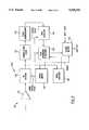
- FIG. 1is a block diagram for a signal processor incorporating an embodiment of the present invention for use in a transmitter.
- FIG. 2is a block diagram for a signal processor incorporating another embodiment of the present invention for use in a transmitter.
- FIG. 3is a block diagram for a signal processor incorporating an embodiment of the present invention for use in a receiver.
- FIG. 4is a block diagram for a two way computer network using a cable television transmission medium incorporating an embodiment of the instant invention.
- FIG. 5is a block diagram for a network node used in the network embodiment of FIG. 4.
- an embodiment of the present inventioncomprises a processor for dynamically controlling the injection level of a secondary signal that is at least partially frequency interleaved into a primary video signal.
- An embodiment of a processor 10is shown in FIG. 1.
- the processor 10is for use in a transmitter and may be part of a TV network hub 210 coupled to a network 208 of FIG. 4.
- This processor 10transmits a primary NTSC video signal 12 with a secondary signal 49.
- the magnitude of the secondary signalis controlled by a dynamic injection level controller 44, which controls the level of injection of the secondary signal 49 into the primary video signal 12.
- Other embodiments of the present inventionmay be used for controlling the injection level of the secondary digital data signal and transmitting digital data at high data rates or analog information with either just an NTSC video signal or another video format such as SECAM or PAL.
- FIG. 1is virtually identical to the embodiment in FIG. 3 of U.S. Pat. No. 5,387,941 to Montgomery et al. filed Sep. 18, 1992, and the description of that embodiment on pages 17 through 23 is incorporated herein by reference.
- the secondary data signalis output by a data section 50 and combined with the output of a video section 20 at an adder 70.
- the secondary signal 49is preferably frequency interleaved with the video signal around non-integral odd quarter multiple of the scanning frequency located by being amplitude modulated with a carrier near the upper end of the video spectrum. This places most of the spectrum of the modulated secondary signal above the chrominance carrier in the chrominance sideband above 3.6 Mhz. To avoid interference with the secondary signal, the portion of the video signal above 3.6 Mhz., and particularly above 3.7 Mhz., is substantially attenuated by a low pass filter 27.
- the instant processordiffers from the embodiment of FIG. 3 of U.S. Pat. No. 5,387,941 to Montgomery et al. filed Sep. 18, 1992, in that a dynamic injection level controller 44 and a video power analyzer 41 are included.
- a dynamic injection level controller 44is coupled between the amplitude modulator 56 and the data equalizer delay amplifier 58.
- the dynamic injection level controller 44may be coupled between the modulator 56 and the adder 70. Alternatively, the injection level could be controlled by altering the power level of the carrier 37.
- the dynamic injection level controller 44takes the rasterized secondary signal from the data equalizer delay amplifier 58 and increases or decreases the amplitude of the secondary signal, and hence the power, before injecting the signal into the modulator 56 for amplitude modulation.
- the dynamic injection level controller 44can be a gain controlled amplifier or the like, where it amplifies or attenuates the power level of the secondary signal in response to either an analog or digital control signal.
- a video power analyzer 41is coupled between the output of the DC restore circuit 24 and the dynamic injection level controller 44.
- the video power analyzertakes the primary video signal 12 to determine the power level of these portions of the chrominance upper sideband of the primary video signal 12 that are attenuated by the low pass filter 27.
- the video power analyzermay for example delay the output of the DC restore circuit 24 by the time delay of the filter 27.
- the output of the filter 27is subtracted from the delayed output to provide a difference signal representative of the attenuation of the filter 27.
- Conventional circuitry or a digital signal processormay then produce a signal proportional to the power attenuated by the filter to control the injection level controller 44 for a time period such as one frame.
- the video power analyzer 41uses the known attenuation characteristics of the filter 27, to generate a control signal to the dynamic injection level controller 44 to dynamically set the level of injection for the secondary signal 49.
- the control signal from the analyzeris such that the secondary signal 49 is injected at a power level that substantially corresponds to the amount of power attenuated from the primary video signal 12. In this way, problems associated with power "head room" limits may be reduced.
- the signal to noise ratio of the transmitted primary signalis not substantially decreased.
- Substantially the same amount of poweris available for amplifying the primary video signal as the injected power of the secondary signal is equal to the attenuated power of the upper chrominance sideband.
- the attenuated portion of the primary signal comprised of the upper chrominance side bandis not needed for most conventional television receivers so the relative, useful signal strength as transmitted remains substantially the same.
- a plurality of video analyzers 41may be used with each video analyzer analyzing the average power in a field, a frame or a line for a different portion of the spectrum.
- the datais more noticeable to the viewer at lower power levels of chroma or luma. Therefore, it is desirable when these conditions exist to lower the injection level of the data, thereby reducing the perceptibility of the data as noise on an ordinary video receiver.
- the injection levelhas been lowered, the ability to separate the data from the video at the receiver remains substantially unchanged as the power level of the video signal has dropped.
- a video analyzer 41may analyze the average power in a line, field, or frame in the luminance portion of the spectrum of the video signal between 600 kilohertz and 1.0 megahertz and a separate video analyzer may analyze the average power in the same line, field, or frame in the chrominance portion and particularly in the spectra above 2.1 Megahertz and preferably below the chrominance carrier at 3.59 MHZ and the lower end of the I and Q sidebands.
- the injection level of the data signalis lowered to limit perceptibility of the data.
- the injection level for the datais increased so that the data may be separated from the video at the receiver.
- the specific function that may be used for controlling the injection level of the data with respect to the detected average powervaries with the particular type of detectors used.
- the control functionmay be determined by empirically altering the data level based upon different combinations of the chrominance and luminance power levels and lowering the injection level until the interference, which appears as "snow" on the receiver is no longer noticeable to an ordinary television receiving the combined signal.
- the resultant control functionmay be stored in a memory as a look-up table (not shown). When the video analyzers 41 detect specific, average power levels for the luminance and chrominance portions of the video signal, these two data are used to look up in the table the appropriate injection level for the data.
- control functionmay be embodied in an analog control circuit contained within the dynamic level injection level controller 44 for providing continuously alterable injection levels.
- the averaging period of the analyzers 41should be selected so that the data injection level is altered quickly enough to avoid perception of the data as "snow" on the screen at an ordinary receiver and to avoid high power luminance or chrominance from interfering with the reception of significance amount of data when the power levels change.
- the processor 10receives error information.
- the error information 94may be generated by a receiver 100 (shown in FIG. 3) which receives the transmitted signal from the processor 10 and is described in more detail below.
- the error information 94contains information correlated to transmission errors detected by the receiver 100 upon reception of the transmitted secondary signal.
- the error information 94provides the dynamic injection level controller 44 with information, in the form of a control word or the like sent over a network, causing the controller 44 to adjust the level of injection of the secondary signal 49 to reduce the transmission errors. For example, if the error information indicates a high error rate, the controller 44 may increase the injection level of the secondary signal 49. Conversely, if the error information indicates a low error rate or no errors, the controller 44 may decrease the injection level of the secondary signal 49. In this way, the secondary signal 49 may be transmitted over long transmission links without unacceptable error rates.
- the dynamic injection level controller 44may inject the secondary signal 49 at selectable levels.
- the injection levelsmay be for example in 3dB increments or may be continuous between -10dB and -30dB with respect to the primary video signal.
- the dynamic injection level controller 44may also decrease the injection level of the secondary signal 49, if no error information 94 is received after a period of time. Further, if the error information is below a predetermined threshold, the dynamic injection level controller 44 may also reduce the injection level of the secondary signal 49.
- the processor 10may have a manual override (not shown) which allows the system operators to override the automatic control provided by the error information 94.
- both the video power analyzer 41 and the error information receiver 42may be used together (not shown). This may allow the processor 10 to further minimize "head room” limitations and reduce transmission errors. Error information may be used to keep the transmission errors at a minimum, and both error information and video analysis may be used to balance the errors versus the amount of power used for amplifying the secondary signal instead of the primary signal. The combined information from the analyzer is used to alter the injected power of the secondary signal 49 to below the attenuated power of the primary video signal 12.
- FIG. 3is virtually identical to the receiver embodiment in FIG. 4 of U.S. Pat. No. 5,387,941 to Montgomery et al. filed Sep. 18, 1992, and the description of that embodiment on pages 23 through 28 is incorporated herein by reference.
- the receiver of FIG. 3is particularly applicable for receiving the transmitted signal.
- the received secondary data signalis output by data section 140 from the RF signal received by the tuner section 110.
- the instant receiverdiffers from the embodiment of FIG. 3 from the processor of FIG. 4 of U.S. Pat. No. 5,387,941 to Montgomery et al. filed Sep. 18, 1992, in that an error detector 167 is included.
- the error detector 167is coupled between the depacketizer 164 and a network 90 or the like.
- the error detector 167determines the transmission errors for the received secondary signal by obtaining error data from the depacketizer 164, where the secondary signal may be received in packets, frames blocks or the like. If the packet, for instance, contains an error detection or correction code, the error detector 167 may determine an error rate by interpreting the results of the correcting or detecting of errors over a period of time.
- the error informationmay comprise the fact that a predetermined number of errors were detected in one or more blocks, packets or frames, that the number of errors detected exceeds the error correcting capacity of the given error correction code or the like. Still further, the error information may comprise a direction or request to increase or decrease the injection level based upon the detected errors. Once the desired parameter relating to errors is determined, the error detector 167 generates error information, containing information such as a control word or the like.
- the error informationis sent out from the receiver 100 to the error information receiver 42 in the separate processor 10 of FIG. 2, through for example, a network (not shown) or the like.
- This received error information 94may then be used by the dynamic injection level controller 44 of FIG. 2 as described above.
- the error detector 167may also feed back the error information only when the error information is above or below predetermined threshold. For example, if an error rate is above a first threshold, the injection level is increased while if the error rate is below a threshold, which may be the same as and different than the first threshold, the injection level is lowered.
- FIGS. 4 and 5show an embodiment where a processor 10 of FIG. 2 and a receiver of FIG. 3 may be used.
- FIGS. 4 and 5are virtually identical to the network embodiment in FIGS. 7-10 of U.S. Pat. No. 5,387,941 to Montgomery et al. filed Sep. 18, 1992, and the description of that embodiment on pages 30 through 34 is incorporated herein by reference.
- the secondary data signal 49is combined with a primary video signal 12 and is transmitted to the network nodes 230 attached to the network hub 210.
- the processor 10 and receiver 100may be part of a satellite communications link.
- the instant networkdiffers from the embodiment of FIGS. 7-10 of U.S. Pat. No. 5,387,941 to Montgomery et al. filed Sep. 18, 1992, in that the network hub 210 has a processor 10 with a dynamic injection level controller 44 as described in FIG. 2 above. Further, the network nodes 230 have receivers 100 which include an error detector 167 and transmitter as described in FIG. 3 above.
- the processor 10in the network hub 210, processes the modulated rasterized secondary signal and combines that modulated signal by injection into the primary signal 12 to provide a combined signal.
- the combined signalis transmitted to the network nodes 230 via network lines 208.
- the injection level of the modulated rasterized version of secondary signal 49is controlled by the injection level controller 44, which amplifies or attenuates the rasterized secondary signal as required.
- the dynamic controller 44may use video analysis from a video power analyzer 41 of FIG. 1 and/or error information 94 generated by the receivers 100 in the network nodes 230 to dynamically control the injection level of the secondary signal 49.
- the network nodes 230shown in FIG. 5, have receivers (data/video decoders) 100 which include an error detector 167. That determines the error rate for the transmitted secondary signal 49 received from the network hub 210.
- the error detector 167 in the data/video decoder 100generates error information 94.
- the error information 94is sent from the data/video decoder 100 to the control unit 236, which then passes the error information 94 to the back channel modulator 234.
- the back channel modulator 234 of network nodes 230may then transmit the error information 94 back to the network hub 210 via lines 208, whenever there is an error or only if it exceeds a predetermined threshold.
- the error information 94is then received by the processor 10 in the network hub 210 and used to dynamically control the injection level of the secondary signal 49.
Landscapes
- Engineering & Computer Science (AREA)
- Multimedia (AREA)
- Signal Processing (AREA)
- Picture Signal Circuits (AREA)
Abstract
Description
Claims (27)
Priority Applications (1)
| Application Number | Priority Date | Filing Date | Title |
|---|---|---|---|
| US08/076,199US5559559A (en) | 1991-06-14 | 1993-06-14 | Transmitting a secondary signal with dynamic injection level control |
Applications Claiming Priority (3)
| Application Number | Priority Date | Filing Date | Title |
|---|---|---|---|
| US07/715,920US5327237A (en) | 1991-06-14 | 1991-06-14 | Transmitting data with video |
| US07/947,134US5387941A (en) | 1991-06-14 | 1992-09-18 | Data with video transmitter |
| US08/076,199US5559559A (en) | 1991-06-14 | 1993-06-14 | Transmitting a secondary signal with dynamic injection level control |
Related Parent Applications (1)
| Application Number | Title | Priority Date | Filing Date |
|---|---|---|---|
| US07/947,134Continuation-In-PartUS5387941A (en) | 1991-06-14 | 1992-09-18 | Data with video transmitter |
Publications (1)
| Publication Number | Publication Date |
|---|---|
| US5559559Atrue US5559559A (en) | 1996-09-24 |
Family
ID=46248795
Family Applications (1)
| Application Number | Title | Priority Date | Filing Date |
|---|---|---|---|
| US08/076,199Expired - Fee RelatedUS5559559A (en) | 1991-06-14 | 1993-06-14 | Transmitting a secondary signal with dynamic injection level control |
Country Status (1)
| Country | Link |
|---|---|
| US (1) | US5559559A (en) |
Cited By (56)
| Publication number | Priority date | Publication date | Assignee | Title |
|---|---|---|---|---|
| US5745604A (en) | 1993-11-18 | 1998-04-28 | Digimarc Corporation | Identification/authentication system using robust, distributed coding |
| US5748763A (en) | 1993-11-18 | 1998-05-05 | Digimarc Corporation | Image steganography system featuring perceptually adaptive and globally scalable signal embedding |
| US5748783A (en) | 1995-05-08 | 1998-05-05 | Digimarc Corporation | Method and apparatus for robust information coding |
| US5809160A (en) | 1992-07-31 | 1998-09-15 | Digimarc Corporation | Method for encoding auxiliary data within a source signal |
| US5822436A (en) | 1996-04-25 | 1998-10-13 | Digimarc Corporation | Photographic products and methods employing embedded information |
| US5832119A (en) | 1993-11-18 | 1998-11-03 | Digimarc Corporation | Methods for controlling systems using control signals embedded in empirical data |
| US5841886A (en) | 1993-11-18 | 1998-11-24 | Digimarc Corporation | Security system for photographic identification |
| US5850481A (en) | 1993-11-18 | 1998-12-15 | Digimarc Corporation | Steganographic system |
| US5862260A (en) | 1993-11-18 | 1999-01-19 | Digimarc Corporation | Methods for surveying dissemination of proprietary empirical data |
| US6094228A (en)* | 1997-10-28 | 2000-07-25 | Ciardullo; Daniel Andrew | Method for transmitting data on viewable portion of a video signal |
| US6122403A (en) | 1995-07-27 | 2000-09-19 | Digimarc Corporation | Computer system linked by using information in data objects |
| US6181713B1 (en)* | 1997-10-27 | 2001-01-30 | Sun Microsystems, Inc. | Selectable depacketizer architecture |
| US6211919B1 (en)* | 1997-03-28 | 2001-04-03 | Tektronix, Inc. | Transparent embedment of data in a video signal |
| US6266430B1 (en) | 1993-11-18 | 2001-07-24 | Digimarc Corporation | Audio or video steganography |
| US6381341B1 (en) | 1996-05-16 | 2002-04-30 | Digimarc Corporation | Watermark encoding method exploiting biases inherent in original signal |
| US6408082B1 (en) | 1996-04-25 | 2002-06-18 | Digimarc Corporation | Watermark detection using a fourier mellin transform |
| US6411623B1 (en) | 1998-12-29 | 2002-06-25 | International Business Machines Corp. | System and method of automated testing of a compressed digital broadcast video network |
| US6414960B1 (en) | 1998-12-29 | 2002-07-02 | International Business Machines Corp. | Apparatus and method of in-service audio/video synchronization testing |
| US20020090114A1 (en)* | 1995-07-27 | 2002-07-11 | Rhoads Geoffrey B. | Watermark enabled video objects |
| US6424725B1 (en) | 1996-05-16 | 2002-07-23 | Digimarc Corporation | Determining transformations of media signals with embedded code signals |
| US6473858B1 (en) | 1999-04-16 | 2002-10-29 | Digeo, Inc. | Method and apparatus for broadcasting data with access control |
| US6519352B2 (en)* | 1994-10-21 | 2003-02-11 | Digimarc Corporation | Encoding and decoding in accordance with steganographically-conveyed data |
| US6567533B1 (en) | 1993-11-18 | 2003-05-20 | Digimarc Corporation | Method and apparatus for discerning image distortion by reference to encoded marker signals |
| US6580819B1 (en) | 1993-11-18 | 2003-06-17 | Digimarc Corporation | Methods of producing security documents having digitally encoded data and documents employing same |
| US6611607B1 (en) | 1993-11-18 | 2003-08-26 | Digimarc Corporation | Integrating digital watermarks in multimedia content |
| US6614914B1 (en) | 1995-05-08 | 2003-09-02 | Digimarc Corporation | Watermark embedder and reader |
| US6625297B1 (en) | 2000-02-10 | 2003-09-23 | Digimarc Corporation | Self-orienting watermarks |
| US6694042B2 (en) | 1999-06-29 | 2004-02-17 | Digimarc Corporation | Methods for determining contents of media |
| US6721440B2 (en) | 1995-05-08 | 2004-04-13 | Digimarc Corporation | Low visibility watermarks using an out-of-phase color |
| US6728390B2 (en) | 1995-05-08 | 2004-04-27 | Digimarc Corporation | Methods and systems using multiple watermarks |
| US20040100588A1 (en)* | 1998-04-17 | 2004-05-27 | Hartson Ted E. | Expanded information capacity for existing communication transmission systems |
| US6757406B2 (en) | 1993-11-18 | 2004-06-29 | Digimarc Corporation | Steganographic image processing |
| US6760463B2 (en) | 1995-05-08 | 2004-07-06 | Digimarc Corporation | Watermarking methods and media |
| US6768809B2 (en) | 2000-02-14 | 2004-07-27 | Digimarc Corporation | Digital watermark screening and detection strategies |
| US6788800B1 (en) | 2000-07-25 | 2004-09-07 | Digimarc Corporation | Authenticating objects using embedded data |
| US6804377B2 (en) | 2000-04-19 | 2004-10-12 | Digimarc Corporation | Detecting information hidden out-of-phase in color channels |
| US6804376B2 (en) | 1998-01-20 | 2004-10-12 | Digimarc Corporation | Equipment employing watermark-based authentication function |
| US6829368B2 (en) | 2000-01-26 | 2004-12-07 | Digimarc Corporation | Establishing and interacting with on-line media collections using identifiers in media signals |
| US6889351B1 (en) | 2000-03-30 | 2005-05-03 | Koninklijke Philips Electronics, N.V. | Backward compatible multiple data stream transmission method and system for compressed domain signals |
| US6917691B2 (en) | 1999-12-28 | 2005-07-12 | Digimarc Corporation | Substituting information based on watermark-enable linking |
| US6922480B2 (en) | 1995-05-08 | 2005-07-26 | Digimarc Corporation | Methods for encoding security documents |
| US20050169255A1 (en)* | 1999-04-16 | 2005-08-04 | Tsutomu Shimomura | Methods and apparatus for broadcasting data |
| US6944298B1 (en) | 1993-11-18 | 2005-09-13 | Digimare Corporation | Steganographic encoding and decoding of auxiliary codes in media signals |
| US6965682B1 (en) | 1999-05-19 | 2005-11-15 | Digimarc Corp | Data transmission by watermark proxy |
| US6968057B2 (en) | 1994-03-17 | 2005-11-22 | Digimarc Corporation | Emulsion products and imagery employing steganography |
| US7027614B2 (en) | 2000-04-19 | 2006-04-11 | Digimarc Corporation | Hiding information to reduce or offset perceptible artifacts |
| US7051111B1 (en) | 2000-04-25 | 2006-05-23 | Digeo, Inc. | Multiple source proxy management system |
| US7180942B2 (en) | 2001-12-18 | 2007-02-20 | Dotcast, Inc. | Joint adaptive optimization of soft decision device and feedback equalizer |
| US20070189533A1 (en)* | 1996-04-25 | 2007-08-16 | Rhoads Geoffrey B | Wireless Methods And Devices Employing Steganography |
| US7486799B2 (en) | 1995-05-08 | 2009-02-03 | Digimarc Corporation | Methods for monitoring audio and images on the internet |
| US7580482B2 (en) | 2003-02-19 | 2009-08-25 | Endres Thomas J | Joint, adaptive control of equalization, synchronization, and gain in a digital communications receiver |
| USRE40919E1 (en)* | 1993-11-18 | 2009-09-22 | Digimarc Corporation | Methods for surveying dissemination of proprietary empirical data |
| US10462413B1 (en)* | 2018-10-26 | 2019-10-29 | Analog Devices Global Unlimited Company | Using metadata for DC offset correction for an AC-coupled video link |
| US20200021776A1 (en)* | 2018-07-13 | 2020-01-16 | Analog Devices Global Unlimited Company | Methods and devices for compensating sag effect |
| US10623692B2 (en) | 2018-07-13 | 2020-04-14 | Analog Devices Global Unlimited Company | High definition analog video and control link for automotive applications |
| US10652127B2 (en) | 2014-10-03 | 2020-05-12 | The Nielsen Company (Us), Llc | Fusing online media monitoring data with secondary online data feeds to generate ratings data for online media exposure |
Citations (92)
| Publication number | Priority date | Publication date | Assignee | Title |
|---|---|---|---|---|
| US2635140A (en)* | 1950-07-28 | 1953-04-14 | Gen Electric | Frequency-interlace television system |
| US2838597A (en)* | 1952-05-01 | 1958-06-10 | Philips Corp | Multiplex television system |
| US3529081A (en)* | 1967-01-11 | 1970-09-15 | Western Union Telegraph Co | Means for applying additional communications signals to existing channels |
| US3530232A (en)* | 1966-06-17 | 1970-09-22 | Intern Telemeter Corp | Subscription television system |
| US3543169A (en)* | 1967-10-30 | 1970-11-24 | Bell Telephone Labor Inc | High speed clamping apparatus employing feedback from sample and hold circuit |
| US3632863A (en)* | 1969-02-16 | 1972-01-04 | Matsushita Electric Industrial Co Ltd | Information transmitting and receiving system employing an audio subcarrier modulated by binary signals |
| US3679816A (en)* | 1971-03-29 | 1972-07-25 | Rca Corp | Control apparatus for a color television receiver |
| US3700793A (en)* | 1970-06-09 | 1972-10-24 | Bell Telephone Labor Inc | Frequency interleaved video multiplex system |
| US3726992A (en)* | 1970-12-07 | 1973-04-10 | Mainichi Broadcasting Syst | Multiplex communication system for transmitting television and facsimile signals |
| US3845326A (en)* | 1972-09-01 | 1974-10-29 | W Godden | Logarithmic amplification circuit |
| US3925639A (en)* | 1974-03-25 | 1975-12-09 | Msi Data Corp | Method and apparatus for reading bar coded data wherein a light source is periodically energized |
| US3927250A (en)* | 1973-02-15 | 1975-12-16 | British Broadcasting Corp | Television system with transmission of auxiliary information |
| US4051532A (en)* | 1975-06-19 | 1977-09-27 | Matsushita Electric Company Of America | Auxiliary signal processing circuit for television receivers |
| US4065784A (en)* | 1976-09-29 | 1977-12-27 | Cbs Inc. | Method and apparatus for PCM-encoding NTSC color television at sub-Nyquist rate |
| US4074199A (en)* | 1974-09-16 | 1978-02-14 | U.S. Philips Corporation | Vestigial-sideband transmission system for synchronous data signals |
| US4141041A (en)* | 1976-09-22 | 1979-02-20 | The Singer Company | Precision gain balance of two video sources for a single display |
| US4155039A (en)* | 1976-08-26 | 1979-05-15 | Thomson-Csf | Two-way transmission system between a main station and secondary stations |
| US4177405A (en)* | 1978-05-05 | 1979-12-04 | Martial Chapdelaine | Photocell-controlled lighting system |
| US4183054A (en)* | 1977-09-30 | 1980-01-08 | Harris Corporation | Digital, frequency-translated, plural-channel, vestigial sideband television communication system |
| US4208630A (en)* | 1978-10-19 | 1980-06-17 | Altran Electronics, Inc. | Narrow band paging or control radio system |
| US4209748A (en)* | 1977-03-03 | 1980-06-24 | Licentia Patent-Verwaltungs-G.M.B.H. | Directional radio system for single sideband operation |
| US4231114A (en)* | 1978-02-27 | 1980-10-28 | Motorola, Inc. | Synchronizing means for a two-way communication system |
| US4354200A (en)* | 1979-12-20 | 1982-10-12 | U.S. Philips Corporation | Amplitude modulator circuit for modulating a video signal on a carrier signal |
| US4379947A (en)* | 1979-02-02 | 1983-04-12 | Teleprompter Corporation | System for transmitting data simultaneously with audio |
| US4424593A (en)* | 1977-09-20 | 1984-01-03 | Kahn Leonard R | Suppressed carrier communications system |
| US4450477A (en)* | 1982-03-31 | 1984-05-22 | Lovett Bruce E | Television information system |
| US4479226A (en)* | 1982-03-29 | 1984-10-23 | At&T Bell Laboratories | Frequency-hopped single sideband mobile radio system |
| US4513415A (en)* | 1979-10-23 | 1985-04-23 | Mcgraw-Edison Company | Broadcast synchronization and supervision system |
| US4538174A (en)* | 1982-03-11 | 1985-08-27 | Communications Patents Limited | Two-way subscriber TV system with multiple subscriber's sets |
| US4539707A (en)* | 1982-06-01 | 1985-09-03 | Aerotron, Inc. | Compressed single side band communications system and method |
| EP0156709A1 (en)* | 1984-03-09 | 1985-10-02 | Societe Internationale De Micro-Informatique Et De Video - Simiv | Method for inserting digital signals in a television signal and decoder for these signals |
| US4551754A (en)* | 1982-02-18 | 1985-11-05 | Rca Corporation | Compatible wide-screen color television system |
| US4556973A (en)* | 1982-11-09 | 1985-12-03 | Pioneer Electronic Corp. | Frequency-division multiplex communication method and system |
| US4578815A (en)* | 1983-12-07 | 1986-03-25 | Motorola, Inc. | Wide area coverage radio communication system and method |
| US4586078A (en)* | 1983-09-12 | 1986-04-29 | Zenith Electronics Corporation | CATV upstream signal transmission at nonharmonic video frequencies |
| JPS6192084A (en)* | 1984-10-11 | 1986-05-10 | Nippon Telegr & Teleph Corp <Ntt> | Data transmission system |
| US4591906A (en)* | 1986-02-12 | 1986-05-27 | Morales Garza Fernando | Wireless transmission from the television set to the television station |
| US4602279A (en)* | 1984-03-21 | 1986-07-22 | Actv, Inc. | Method for providing targeted profile interactive CATV displays |
| US4622694A (en)* | 1983-08-20 | 1986-11-11 | Ant Nachrichtentechnik Gmbh | Transmission system for TV signals on radio links |
| US4626913A (en)* | 1984-06-26 | 1986-12-02 | Rca Corporation | Chroma burst derived clock regenerator for teletext decoder |
| US4639786A (en)* | 1985-10-23 | 1987-01-27 | Rca Corporation | Television sound signal processor |
| US4647983A (en)* | 1983-09-30 | 1987-03-03 | Victor Company Of Japan Ltd. | Method and apparatus for recording and/or reproducing color video signal |
| US4660072A (en)* | 1983-03-18 | 1987-04-21 | Hitachi, Ltd. | Television signal transmission system |
| US4665431A (en)* | 1982-06-24 | 1987-05-12 | Cooper J Carl | Apparatus and method for receiving audio signals transmitted as part of a television video signal |
| US4670773A (en)* | 1984-09-26 | 1987-06-02 | Ant Nachrichtentechnik Gmbh | Method for compatible increase in resolution for color television transmission systems with reduction of cross-talk noise in motion adaptive picture processing |
| US4688097A (en)* | 1986-10-30 | 1987-08-18 | Jerrold Electronics Corp. | D.C.-coupled video clamping circuit |
| JPS62206990A (en)* | 1986-03-07 | 1987-09-11 | Nippon Hoso Kyokai <Nhk> | Band compressing system for component video signal |
| US4695900A (en)* | 1984-04-12 | 1987-09-22 | Matsushita Electric Industrial Co., Ltd. | Magnetic recording and playback apparatus for teletext signals |
| JPS62236288A (en)* | 1986-04-08 | 1987-10-16 | Nippon Hoso Kyokai <Nhk> | Multiplex signal transmission system |
| EP0246698A2 (en)* | 1986-05-22 | 1987-11-25 | Philips Patentverwaltung GmbH | Circuit arrangement for a television receiver provided with a teletext decoder |
| JPS6346084A (en)* | 1986-08-13 | 1988-02-26 | Hitachi Ltd | Television signal transmission method |
| EP0263449A2 (en)* | 1986-10-04 | 1988-04-13 | Bayerische Rundfunkwerbung GmbH | Method for broadcasting digital sound signals |
| JPS6386987A (en)* | 1986-09-30 | 1988-04-18 | Matsushita Electric Ind Co Ltd | Television signal transmitter/receiver |
| US4745476A (en)* | 1984-02-15 | 1988-05-17 | Matsushita Electric Industrial Co., Ltd. | Television sound signal processing apparatus |
| US4750206A (en)* | 1986-10-28 | 1988-06-07 | Recoton Corporation | Adapter for TV stereo, SAP and auxiliary signals |
| US4750036A (en)* | 1986-05-14 | 1988-06-07 | Radio Telcom & Technology, Inc. | Interactive television and data transmission system |
| EP0278192A1 (en)* | 1986-12-24 | 1988-08-17 | France Telecom | Method for digitally broadcasting in television channels |
| US4805020A (en)* | 1983-03-21 | 1989-02-14 | Greenberg Burton L | Television program transmission verification method and apparatus |
| US4807031A (en)* | 1987-10-20 | 1989-02-21 | Interactive Systems, Incorporated | Interactive video method and apparatus |
| EP0308241A2 (en)* | 1987-09-18 | 1989-03-22 | Matsushita Electric Industrial Co., Ltd. | Multiplex signal processing apparatus |
| JPS6489886A (en)* | 1987-09-30 | 1989-04-05 | Sony Corp | Composite video signal forming circuit |
| US4831443A (en)* | 1987-09-08 | 1989-05-16 | Zenith Electronics Corporation | Wide band VCR with comb filter inhibition |
| US4855811A (en)* | 1987-09-14 | 1989-08-08 | General Electric Company | Apparatus for processing auxiliary information in an extended definition widescreen television system |
| US4879606A (en)* | 1988-06-06 | 1989-11-07 | General Electric Company | EDTV recording apparatus |
| EP0356903A2 (en)* | 1988-09-01 | 1990-03-07 | Yves Charles Faroudja | Television transmission system having improved separation of audio and video spectra |
| EP0360615A2 (en)* | 1988-09-23 | 1990-03-28 | The Grass Valley Group, Inc. | Embedment of data in a video signal |
| EP0365431A1 (en)* | 1988-10-21 | 1990-04-25 | Thomson-Csf | Transmitter, transmission method and receiver |
| US4958230A (en)* | 1989-08-11 | 1990-09-18 | General Electric Company | Method of transmitting auxiliary information in a television signal |
| US4985769A (en)* | 1988-03-23 | 1991-01-15 | Matsushita Electric Industrial Co., Ltd. | Multiplex TV signal processing apparatus |
| US5014125A (en)* | 1989-05-05 | 1991-05-07 | Cableshare, Inc. | Television system for the interactive distribution of selectable video presentations |
| JPH03148979A (en)* | 1989-11-02 | 1991-06-25 | Matsushita Electric Ind Co Ltd | pre-processing filter |
| US5029003A (en)* | 1989-12-18 | 1991-07-02 | General Electric Company | Apparatus for incorporating digital signals with a standard TV signal |
| US5057920A (en)* | 1989-02-28 | 1991-10-15 | Sony Corporation | Video signal clamping circuit operating in the digital domain for removing excess noise on the black level and for providing d c restoration |
| US5063446A (en)* | 1989-08-11 | 1991-11-05 | General Electric Company | Apparatus for transmitting auxiliary signal in a TV channel |
| US5075773A (en)* | 1987-12-07 | 1991-12-24 | British Broadcasting Corporation | Data transmission in active picture period |
| US5103297A (en)* | 1990-02-16 | 1992-04-07 | Matsushita Electric Industrial Co., Ltd. | Apparatus for carrying out y/c separation |
| US5103310A (en)* | 1990-07-20 | 1992-04-07 | General Electric Company | Interference reduction for extra-spectrum, compatible television system |
| US5136411A (en)* | 1987-12-11 | 1992-08-04 | General Instrument Corporation | Dynamically responsive CATV system with shared fiber optic link |
| US5142354A (en)* | 1989-12-27 | 1992-08-25 | Fuji Photo Optical Co., Ltd. | Signal level correction circuit for a video signal |
| US5157491A (en)* | 1988-10-17 | 1992-10-20 | Kassatly L Samuel A | Method and apparatus for video broadcasting and teleconferencing |
| US5157359A (en)* | 1990-03-13 | 1992-10-20 | Sharp Kabushiki Kaisha | Carrier reset fm modulator and method of frequency modulating video signals |
| US5172413A (en)* | 1990-12-20 | 1992-12-15 | Sasktel | Secure hierarchial video delivery system and method |
| WO1992022984A1 (en)* | 1991-06-14 | 1992-12-23 | Wavephore, Inc. | Transmitting data with a video signal |
| US5177604A (en)* | 1986-05-14 | 1993-01-05 | Radio Telcom & Technology, Inc. | Interactive television and data transmission system |
| EP0530669A2 (en)* | 1991-09-06 | 1993-03-10 | Nippon Television Network Corporation | Encoder/decoder for information signal |
| US5200822A (en)* | 1991-04-23 | 1993-04-06 | National Broadcasting Company, Inc. | Arrangement for and method of processing data, especially for identifying and verifying airing of television broadcast programs |
| US5243423A (en)* | 1991-12-20 | 1993-09-07 | A. C. Nielsen Company | Spread spectrum digital data transmission over TV video |
| WO1994006627A1 (en)* | 1992-09-21 | 1994-03-31 | Ferro Corporation | Composites and polymer compositions for making the same |
| US5315617A (en)* | 1992-05-29 | 1994-05-24 | General Electric Company | QAM encoding for high-definition television system |
| US5319455A (en)* | 1990-09-28 | 1994-06-07 | Ictv Inc. | System for distributing customized commercials to television viewers |
| US5387941A (en)* | 1991-06-14 | 1995-02-07 | Wavephore, Inc. | Data with video transmitter |
| US5410360A (en)* | 1991-06-14 | 1995-04-25 | Wavephore, Inc. | Timing control for injecting a burst and data into a video signal |
- 1993
- 1993-06-14USUS08/076,199patent/US5559559A/ennot_activeExpired - Fee Related
Patent Citations (96)
| Publication number | Priority date | Publication date | Assignee | Title |
|---|---|---|---|---|
| US2635140A (en)* | 1950-07-28 | 1953-04-14 | Gen Electric | Frequency-interlace television system |
| US2838597A (en)* | 1952-05-01 | 1958-06-10 | Philips Corp | Multiplex television system |
| US3530232A (en)* | 1966-06-17 | 1970-09-22 | Intern Telemeter Corp | Subscription television system |
| US3529081A (en)* | 1967-01-11 | 1970-09-15 | Western Union Telegraph Co | Means for applying additional communications signals to existing channels |
| US3543169A (en)* | 1967-10-30 | 1970-11-24 | Bell Telephone Labor Inc | High speed clamping apparatus employing feedback from sample and hold circuit |
| US3632863A (en)* | 1969-02-16 | 1972-01-04 | Matsushita Electric Industrial Co Ltd | Information transmitting and receiving system employing an audio subcarrier modulated by binary signals |
| US3700793A (en)* | 1970-06-09 | 1972-10-24 | Bell Telephone Labor Inc | Frequency interleaved video multiplex system |
| US3726992A (en)* | 1970-12-07 | 1973-04-10 | Mainichi Broadcasting Syst | Multiplex communication system for transmitting television and facsimile signals |
| US3679816A (en)* | 1971-03-29 | 1972-07-25 | Rca Corp | Control apparatus for a color television receiver |
| US3845326A (en)* | 1972-09-01 | 1974-10-29 | W Godden | Logarithmic amplification circuit |
| US3927250A (en)* | 1973-02-15 | 1975-12-16 | British Broadcasting Corp | Television system with transmission of auxiliary information |
| US3925639A (en)* | 1974-03-25 | 1975-12-09 | Msi Data Corp | Method and apparatus for reading bar coded data wherein a light source is periodically energized |
| US4074199A (en)* | 1974-09-16 | 1978-02-14 | U.S. Philips Corporation | Vestigial-sideband transmission system for synchronous data signals |
| US4051532A (en)* | 1975-06-19 | 1977-09-27 | Matsushita Electric Company Of America | Auxiliary signal processing circuit for television receivers |
| US4155039A (en)* | 1976-08-26 | 1979-05-15 | Thomson-Csf | Two-way transmission system between a main station and secondary stations |
| US4141041A (en)* | 1976-09-22 | 1979-02-20 | The Singer Company | Precision gain balance of two video sources for a single display |
| US4065784A (en)* | 1976-09-29 | 1977-12-27 | Cbs Inc. | Method and apparatus for PCM-encoding NTSC color television at sub-Nyquist rate |
| US4209748A (en)* | 1977-03-03 | 1980-06-24 | Licentia Patent-Verwaltungs-G.M.B.H. | Directional radio system for single sideband operation |
| US4424593A (en)* | 1977-09-20 | 1984-01-03 | Kahn Leonard R | Suppressed carrier communications system |
| US4183054A (en)* | 1977-09-30 | 1980-01-08 | Harris Corporation | Digital, frequency-translated, plural-channel, vestigial sideband television communication system |
| US4231114A (en)* | 1978-02-27 | 1980-10-28 | Motorola, Inc. | Synchronizing means for a two-way communication system |
| US4177405A (en)* | 1978-05-05 | 1979-12-04 | Martial Chapdelaine | Photocell-controlled lighting system |
| US4208630A (en)* | 1978-10-19 | 1980-06-17 | Altran Electronics, Inc. | Narrow band paging or control radio system |
| US4379947A (en)* | 1979-02-02 | 1983-04-12 | Teleprompter Corporation | System for transmitting data simultaneously with audio |
| US4513415A (en)* | 1979-10-23 | 1985-04-23 | Mcgraw-Edison Company | Broadcast synchronization and supervision system |
| US4354200A (en)* | 1979-12-20 | 1982-10-12 | U.S. Philips Corporation | Amplitude modulator circuit for modulating a video signal on a carrier signal |
| US4551754A (en)* | 1982-02-18 | 1985-11-05 | Rca Corporation | Compatible wide-screen color television system |
| US4538174A (en)* | 1982-03-11 | 1985-08-27 | Communications Patents Limited | Two-way subscriber TV system with multiple subscriber's sets |
| US4479226A (en)* | 1982-03-29 | 1984-10-23 | At&T Bell Laboratories | Frequency-hopped single sideband mobile radio system |
| US4450477A (en)* | 1982-03-31 | 1984-05-22 | Lovett Bruce E | Television information system |
| US4539707A (en)* | 1982-06-01 | 1985-09-03 | Aerotron, Inc. | Compressed single side band communications system and method |
| US4665431A (en)* | 1982-06-24 | 1987-05-12 | Cooper J Carl | Apparatus and method for receiving audio signals transmitted as part of a television video signal |
| US4556973A (en)* | 1982-11-09 | 1985-12-03 | Pioneer Electronic Corp. | Frequency-division multiplex communication method and system |
| US4660072A (en)* | 1983-03-18 | 1987-04-21 | Hitachi, Ltd. | Television signal transmission system |
| US4805020A (en)* | 1983-03-21 | 1989-02-14 | Greenberg Burton L | Television program transmission verification method and apparatus |
| US4622694A (en)* | 1983-08-20 | 1986-11-11 | Ant Nachrichtentechnik Gmbh | Transmission system for TV signals on radio links |
| US4586078A (en)* | 1983-09-12 | 1986-04-29 | Zenith Electronics Corporation | CATV upstream signal transmission at nonharmonic video frequencies |
| US4647983A (en)* | 1983-09-30 | 1987-03-03 | Victor Company Of Japan Ltd. | Method and apparatus for recording and/or reproducing color video signal |
| US4578815A (en)* | 1983-12-07 | 1986-03-25 | Motorola, Inc. | Wide area coverage radio communication system and method |
| US4745476A (en)* | 1984-02-15 | 1988-05-17 | Matsushita Electric Industrial Co., Ltd. | Television sound signal processing apparatus |
| EP0156709A1 (en)* | 1984-03-09 | 1985-10-02 | Societe Internationale De Micro-Informatique Et De Video - Simiv | Method for inserting digital signals in a television signal and decoder for these signals |
| US4602279A (en)* | 1984-03-21 | 1986-07-22 | Actv, Inc. | Method for providing targeted profile interactive CATV displays |
| US4695900A (en)* | 1984-04-12 | 1987-09-22 | Matsushita Electric Industrial Co., Ltd. | Magnetic recording and playback apparatus for teletext signals |
| US4626913A (en)* | 1984-06-26 | 1986-12-02 | Rca Corporation | Chroma burst derived clock regenerator for teletext decoder |
| US4670773A (en)* | 1984-09-26 | 1987-06-02 | Ant Nachrichtentechnik Gmbh | Method for compatible increase in resolution for color television transmission systems with reduction of cross-talk noise in motion adaptive picture processing |
| JPS6192084A (en)* | 1984-10-11 | 1986-05-10 | Nippon Telegr & Teleph Corp <Ntt> | Data transmission system |
| US4639786A (en)* | 1985-10-23 | 1987-01-27 | Rca Corporation | Television sound signal processor |
| US4591906A (en)* | 1986-02-12 | 1986-05-27 | Morales Garza Fernando | Wireless transmission from the television set to the television station |
| JPS62206990A (en)* | 1986-03-07 | 1987-09-11 | Nippon Hoso Kyokai <Nhk> | Band compressing system for component video signal |
| JPS62236288A (en)* | 1986-04-08 | 1987-10-16 | Nippon Hoso Kyokai <Nhk> | Multiplex signal transmission system |
| US4750036A (en)* | 1986-05-14 | 1988-06-07 | Radio Telcom & Technology, Inc. | Interactive television and data transmission system |
| US5177604A (en)* | 1986-05-14 | 1993-01-05 | Radio Telcom & Technology, Inc. | Interactive television and data transmission system |
| EP0246698A2 (en)* | 1986-05-22 | 1987-11-25 | Philips Patentverwaltung GmbH | Circuit arrangement for a television receiver provided with a teletext decoder |
| US4800428A (en)* | 1986-05-22 | 1989-01-24 | U.S. Philips Corporation | Circuit arrangement for a television receiver comprising a video text decoder |
| JPS6346084A (en)* | 1986-08-13 | 1988-02-26 | Hitachi Ltd | Television signal transmission method |
| JPS6386987A (en)* | 1986-09-30 | 1988-04-18 | Matsushita Electric Ind Co Ltd | Television signal transmitter/receiver |
| EP0263449A2 (en)* | 1986-10-04 | 1988-04-13 | Bayerische Rundfunkwerbung GmbH | Method for broadcasting digital sound signals |
| US4750206A (en)* | 1986-10-28 | 1988-06-07 | Recoton Corporation | Adapter for TV stereo, SAP and auxiliary signals |
| US4688097A (en)* | 1986-10-30 | 1987-08-18 | Jerrold Electronics Corp. | D.C.-coupled video clamping circuit |
| US4884139A (en)* | 1986-12-24 | 1989-11-28 | Etat Francais, Represente Par Le Secretariat D'etat Aux Post Es Et Telecommunications (Centre National D'etudes Des Telecommunications) | Method of digital sound broadcasting in television channels with spectrum interlacing |
| EP0278192A1 (en)* | 1986-12-24 | 1988-08-17 | France Telecom | Method for digitally broadcasting in television channels |
| US4831443A (en)* | 1987-09-08 | 1989-05-16 | Zenith Electronics Corporation | Wide band VCR with comb filter inhibition |
| US4855811A (en)* | 1987-09-14 | 1989-08-08 | General Electric Company | Apparatus for processing auxiliary information in an extended definition widescreen television system |
| EP0308241A2 (en)* | 1987-09-18 | 1989-03-22 | Matsushita Electric Industrial Co., Ltd. | Multiplex signal processing apparatus |
| JPS6489886A (en)* | 1987-09-30 | 1989-04-05 | Sony Corp | Composite video signal forming circuit |
| US4807031A (en)* | 1987-10-20 | 1989-02-21 | Interactive Systems, Incorporated | Interactive video method and apparatus |
| US5075773A (en)* | 1987-12-07 | 1991-12-24 | British Broadcasting Corporation | Data transmission in active picture period |
| US5136411A (en)* | 1987-12-11 | 1992-08-04 | General Instrument Corporation | Dynamically responsive CATV system with shared fiber optic link |
| US4985769A (en)* | 1988-03-23 | 1991-01-15 | Matsushita Electric Industrial Co., Ltd. | Multiplex TV signal processing apparatus |
| US4879606A (en)* | 1988-06-06 | 1989-11-07 | General Electric Company | EDTV recording apparatus |
| EP0356903A2 (en)* | 1988-09-01 | 1990-03-07 | Yves Charles Faroudja | Television transmission system having improved separation of audio and video spectra |
| US4969041A (en)* | 1988-09-23 | 1990-11-06 | Dubner Computer Systems, Inc. | Embedment of data in a video signal |
| EP0360615A2 (en)* | 1988-09-23 | 1990-03-28 | The Grass Valley Group, Inc. | Embedment of data in a video signal |
| US5157491A (en)* | 1988-10-17 | 1992-10-20 | Kassatly L Samuel A | Method and apparatus for video broadcasting and teleconferencing |
| EP0365431A1 (en)* | 1988-10-21 | 1990-04-25 | Thomson-Csf | Transmitter, transmission method and receiver |
| US5057920A (en)* | 1989-02-28 | 1991-10-15 | Sony Corporation | Video signal clamping circuit operating in the digital domain for removing excess noise on the black level and for providing d c restoration |
| US5014125A (en)* | 1989-05-05 | 1991-05-07 | Cableshare, Inc. | Television system for the interactive distribution of selectable video presentations |
| US5063446A (en)* | 1989-08-11 | 1991-11-05 | General Electric Company | Apparatus for transmitting auxiliary signal in a TV channel |
| US4958230A (en)* | 1989-08-11 | 1990-09-18 | General Electric Company | Method of transmitting auxiliary information in a television signal |
| JPH03148979A (en)* | 1989-11-02 | 1991-06-25 | Matsushita Electric Ind Co Ltd | pre-processing filter |
| US5029003A (en)* | 1989-12-18 | 1991-07-02 | General Electric Company | Apparatus for incorporating digital signals with a standard TV signal |
| US5142354A (en)* | 1989-12-27 | 1992-08-25 | Fuji Photo Optical Co., Ltd. | Signal level correction circuit for a video signal |
| US5103297A (en)* | 1990-02-16 | 1992-04-07 | Matsushita Electric Industrial Co., Ltd. | Apparatus for carrying out y/c separation |
| US5157359A (en)* | 1990-03-13 | 1992-10-20 | Sharp Kabushiki Kaisha | Carrier reset fm modulator and method of frequency modulating video signals |
| US5103310A (en)* | 1990-07-20 | 1992-04-07 | General Electric Company | Interference reduction for extra-spectrum, compatible television system |
| US5319455A (en)* | 1990-09-28 | 1994-06-07 | Ictv Inc. | System for distributing customized commercials to television viewers |
| US5172413A (en)* | 1990-12-20 | 1992-12-15 | Sasktel | Secure hierarchial video delivery system and method |
| US5200822A (en)* | 1991-04-23 | 1993-04-06 | National Broadcasting Company, Inc. | Arrangement for and method of processing data, especially for identifying and verifying airing of television broadcast programs |
| WO1992022984A1 (en)* | 1991-06-14 | 1992-12-23 | Wavephore, Inc. | Transmitting data with a video signal |
| US5327237A (en)* | 1991-06-14 | 1994-07-05 | Wavephore, Inc. | Transmitting data with video |
| US5387941A (en)* | 1991-06-14 | 1995-02-07 | Wavephore, Inc. | Data with video transmitter |
| US5410360A (en)* | 1991-06-14 | 1995-04-25 | Wavephore, Inc. | Timing control for injecting a burst and data into a video signal |
| EP0530669A2 (en)* | 1991-09-06 | 1993-03-10 | Nippon Television Network Corporation | Encoder/decoder for information signal |
| US5243423A (en)* | 1991-12-20 | 1993-09-07 | A. C. Nielsen Company | Spread spectrum digital data transmission over TV video |
| US5315617A (en)* | 1992-05-29 | 1994-05-24 | General Electric Company | QAM encoding for high-definition television system |
| WO1994006627A1 (en)* | 1992-09-21 | 1994-03-31 | Ferro Corporation | Composites and polymer compositions for making the same |
Non-Patent Citations (23)
| Title |
|---|
| Christiansen, M.; T. R ste; and J. N. Skalvik, A Video Scrambler/Descrambler Concept for the PAL Format, Journal of the Institution of Electronic and Radio Engineers, vol. 57, No. 1, Jan./Feb. 1987 pp. 27 35.* |
| Christiansen, M.; T. R.o slashed.ste; and J. N. Skalvik, A Video Scrambler/Descrambler Concept for the PAL Format, Journal of the Institution of Electronic and Radio Engineers, vol. 57, No. 1, Jan./Feb. 1987 pp. 27-35. |
| Genesys: Transmission System for HDTV.* |
| Gerdes, Richard, "Arizona Based HDTV:; The Genesys™ Technologies." Presented at Phoenix Chapter of the Society of Broadcast Engineers, Arizona Broadcasters Association Fall Meeting, November 10, 1989. Phoenix, AZ. |
| Gerdes, Richard, "Genesys™ HDTV Technologies Expand Existing NTSC Service", Presented at the 24th Annual SMPTE Television Conference, Society of Motion Picture and Television Engineers, Jan. 1990, Lake Buena Vista, FL. |
| Gerdes, Richard, "HDTV Management Timetable." Presented at Challenges in Teleproduction, The Internat'l Teleproduction Society Annual Forum, Sep. 17, 1989. Los Angeles, CA. |
| Gerdes, Richard, "The Use of Genesys™ Technology for HDTV". Presented at the 130th SMPTE Technical Conference, Society of Motion Picture and Television Engineers, Inc., Oct. 15-19, 1988. |
| Gerdes, Richard, "Using Genesys™ HDTV Technologies for Today's Expanded NTSC Service". Presented at 1990 Spring Engineering Conference, National Association of Broadcasters, Apr. 1, 1990. Atlanta, GA. |
| Gerdes, Richard, "Waveform Modulation as Used in Television Applications". Presented at RF Technology Expo 90, Mar. 28, 1990. Anaheim, CA. |
| Gerdes, Richard, Arizona Based HDTV:; The Genesys Technologies. Presented at Phoenix Chapter of the Society of Broadcast Engineers, Arizona Broadcasters Association Fall Meeting, November 10, 1989. Phoenix, AZ.* |
| Gerdes, Richard, Genesys HDTV Technologies Expand Existing NTSC Service , Presented at the 24th Annual SMPTE Television Conference, Society of Motion Picture and Television Engineers, Jan. 1990, Lake Buena Vista, FL.* |
| Gerdes, Richard, HDTV Management Timetable. Presented at Challenges in Teleproduction, The Internat l Teleproduction Society Annual Forum, Sep. 17, 1989. Los Angeles, CA.* |
| Gerdes, Richard, The Use of Genesys Technology for HDTV . Presented at the 130th SMPTE Technical Conference, Society of Motion Picture and Television Engineers, Inc., Oct. 15 19, 1988.* |
| Gerdes, Richard, Using Genesys HDTV Technologies for Today s Expanded NTSC Service . Presented at 1990 Spring Engineering Conference, National Association of Broadcasters, Apr. 1, 1990. Atlanta, GA.* |
| Gerdes, Richard, Waveform Modulation as Used in Television Applications . Presented at RF Technology Expo 90, Mar. 28, 1990. Anaheim, CA.* |
| International Search Report for International Application No. PCT/US92/03711 filed Apr. 5, 1992.* |
| Intnl. Search Report nfor Intnl. Application No. PCT/US92/10406 filed Oct. 7, 1993.* |
| King, Patrick T., "A Novel TV Add-On Data Communication System," I.E.E.E. Transactions on Broadcast and Television, vol. BTR-19, No. 4, pp. 225-230; Nov. 1973. |
| King, Patrick T., A Novel TV Add On Data Communication System, I.E.E.E. Transactions on Broadcast and Television, vol. BTR 19, No. 4, pp. 225 230; Nov. 1973.* |
| King, Patrick T., A. Novel Television Add On Data Communication System, Journal of the SMPTE, vol. 83, Jan. 1974, pp. 10 13.* |
| King, Patrick T., A. Novel Television Add-On Data Communication System, Journal of the SMPTE, vol. 83, Jan. 1974, pp. 10-13. |
| Maebara, Akiyoski and Seizo Tamai, A Television Facsimile System Employing an Additional Carrier, New Broadcasting System Research Group, Serial No. 151, Feb. 1972.* |
| Tomasi, Wayne, Electronic Communications Systems: Fundamentals Through Advanced Prentice Hall, New Jersey, 1988, p. 481.* |
Cited By (141)
| Publication number | Priority date | Publication date | Assignee | Title |
|---|---|---|---|---|
| US7978876B2 (en) | 1992-07-31 | 2011-07-12 | Digimarc Corporation | Hiding codes in input data |
| US20050147276A1 (en)* | 1992-07-31 | 2005-07-07 | Powell Robert D. | Decoding hidden data from imagery |
| US7062070B2 (en) | 1992-07-31 | 2006-06-13 | Digimarc Corporation | Image marking adapted to the image |
| US20050117776A1 (en)* | 1992-07-31 | 2005-06-02 | Digimarc Corporation | Image marking adapted to the image |
| US5809160A (en) | 1992-07-31 | 1998-09-15 | Digimarc Corporation | Method for encoding auxiliary data within a source signal |
| US6628801B2 (en) | 1992-07-31 | 2003-09-30 | Digimarc Corporation | Image marking with pixel modification |
| US7068812B2 (en) | 1992-07-31 | 2006-06-27 | Digimarc Corporation | Decoding hidden data from imagery |
| US6614915B2 (en) | 1992-07-31 | 2003-09-02 | Digimarc Corporation | Image capture and marking |
| US7068811B2 (en) | 1992-07-31 | 2006-06-27 | Digimarc Corporation | Protecting images with image markings |
| US6459803B1 (en) | 1992-07-31 | 2002-10-01 | Digimarc Corporation | Method for encoding auxiliary data within a source signal |
| US5930377A (en) | 1992-07-31 | 1999-07-27 | Digimarc Corporation | Method for image encoding |
| US7136503B2 (en) | 1992-07-31 | 2006-11-14 | Digimarc Corporation | Encoding hidden data |
| US7412074B2 (en) | 1992-07-31 | 2008-08-12 | Digimarc Corporation | Hiding codes in input data |
| US7593545B2 (en) | 1992-07-31 | 2009-09-22 | Digimarc Corporation | Determining whether two or more creative works correspond |
| US20030228031A1 (en)* | 1993-11-18 | 2003-12-11 | Rhoads Geoffrey B. | Methods for marking images |
| US6580819B1 (en) | 1993-11-18 | 2003-06-17 | Digimarc Corporation | Methods of producing security documents having digitally encoded data and documents employing same |
| US7711143B2 (en) | 1993-11-18 | 2010-05-04 | Digimarc Corporation | Methods for marking images |
| US5748763A (en) | 1993-11-18 | 1998-05-05 | Digimarc Corporation | Image steganography system featuring perceptually adaptive and globally scalable signal embedding |
| USRE40919E1 (en)* | 1993-11-18 | 2009-09-22 | Digimarc Corporation | Methods for surveying dissemination of proprietary empirical data |
| US7522728B1 (en) | 1993-11-18 | 2009-04-21 | Digimarc Corporation | Wireless methods and devices employing steganography |
| US6266430B1 (en) | 1993-11-18 | 2001-07-24 | Digimarc Corporation | Audio or video steganography |
| US6330335B1 (en) | 1993-11-18 | 2001-12-11 | Digimarc Corporation | Audio steganography |
| US6343138B1 (en) | 1993-11-18 | 2002-01-29 | Digimarc Corporation | Security documents with hidden digital data |
| US6353672B1 (en)* | 1993-11-18 | 2002-03-05 | Digimarc Corporation | Steganography using dynamic codes |
| US6944298B1 (en) | 1993-11-18 | 2005-09-13 | Digimare Corporation | Steganographic encoding and decoding of auxiliary codes in media signals |
| US6363159B1 (en) | 1993-11-18 | 2002-03-26 | Digimarc Corporation | Consumer audio appliance responsive to watermark data |
| US8204222B2 (en) | 1993-11-18 | 2012-06-19 | Digimarc Corporation | Steganographic encoding and decoding of auxiliary codes in media signals |
| US6400827B1 (en) | 1993-11-18 | 2002-06-04 | Digimarc Corporation | Methods for hiding in-band digital data in images and video |
| US6404898B1 (en) | 1993-11-18 | 2002-06-11 | Digimarc Corporation | Method and system for encoding image and audio content |
| US6959386B2 (en) | 1993-11-18 | 2005-10-25 | Digimarc Corporation | Hiding encrypted messages in information carriers |
| US7308110B2 (en) | 1993-11-18 | 2007-12-11 | Digimarc Corporation | Methods for marking images |
| US7181022B2 (en) | 1993-11-18 | 2007-02-20 | Digimarc Corporation | Audio watermarking to convey auxiliary information, and media embodying same |
| US7171016B1 (en) | 1993-11-18 | 2007-01-30 | Digimarc Corporation | Method for monitoring internet dissemination of image, video and/or audio files |
| US6026193A (en) | 1993-11-18 | 2000-02-15 | Digimarc Corporation | Video steganography |
| US6430302B2 (en) | 1993-11-18 | 2002-08-06 | Digimarc Corporation | Steganographically encoding a first image in accordance with a second image |
| US6975746B2 (en) | 1993-11-18 | 2005-12-13 | Digimarc Corporation | Integrating digital watermarks in multimedia content |
| US5862260A (en) | 1993-11-18 | 1999-01-19 | Digimarc Corporation | Methods for surveying dissemination of proprietary empirical data |
| US6983051B1 (en) | 1993-11-18 | 2006-01-03 | Digimarc Corporation | Methods for audio watermarking and decoding |
| US6496591B1 (en) | 1993-11-18 | 2002-12-17 | Digimarc Corporation | Video copy-control with plural embedded signals |
| US5745604A (en) | 1993-11-18 | 1998-04-28 | Digimarc Corporation | Identification/authentication system using robust, distributed coding |
| US6539095B1 (en) | 1993-11-18 | 2003-03-25 | Geoffrey B. Rhoads | Audio watermarking to convey auxiliary control information, and media embodying same |
| US6542620B1 (en) | 1993-11-18 | 2003-04-01 | Digimarc Corporation | Signal processing to hide plural-bit information in image, video, and audio data |
| US5850481A (en) | 1993-11-18 | 1998-12-15 | Digimarc Corporation | Steganographic system |
| US6987862B2 (en) | 1993-11-18 | 2006-01-17 | Digimarc Corporation | Video steganography |
| US6567780B2 (en) | 1993-11-18 | 2003-05-20 | Digimarc Corporation | Audio with hidden in-band digital data |
| US6567533B1 (en) | 1993-11-18 | 2003-05-20 | Digimarc Corporation | Method and apparatus for discerning image distortion by reference to encoded marker signals |
| US6567535B2 (en) | 1993-11-18 | 2003-05-20 | Digimarc Corporation | Steganographic system with changing operations |
| US6122392A (en) | 1993-11-18 | 2000-09-19 | Digimarc Corporation | Signal processing to hide plural-bit information in image, video, and audio data |
| US6587821B1 (en) | 1993-11-18 | 2003-07-01 | Digimarc Corp | Methods for decoding watermark data from audio, and controlling audio devices in accordance therewith |
| US6611607B1 (en) | 1993-11-18 | 2003-08-26 | Digimarc Corporation | Integrating digital watermarks in multimedia content |
| US5841886A (en) | 1993-11-18 | 1998-11-24 | Digimarc Corporation | Security system for photographic identification |
| US6757406B2 (en) | 1993-11-18 | 2004-06-29 | Digimarc Corporation | Steganographic image processing |
| US7003132B2 (en) | 1993-11-18 | 2006-02-21 | Digimarc Corporation | Embedding hidden auxiliary code signals in media |
| US5832119A (en) | 1993-11-18 | 1998-11-03 | Digimarc Corporation | Methods for controlling systems using control signals embedded in empirical data |
| US8391541B2 (en) | 1993-11-18 | 2013-03-05 | Digimarc Corporation | Steganographic encoding and detecting for video signals |
| US6654480B2 (en) | 1993-11-18 | 2003-11-25 | Digimarc Corporation | Audio appliance and monitoring device responsive to watermark data |
| US5768426A (en) | 1993-11-18 | 1998-06-16 | Digimarc Corporation | Graphics processing system employing embedded code signals |
| US6675146B2 (en) | 1993-11-18 | 2004-01-06 | Digimarc Corporation | Audio steganography |
| US6700990B1 (en) | 1993-11-18 | 2004-03-02 | Digimarc Corporation | Digital watermark decoding method |
| US6111954A (en) | 1994-03-17 | 2000-08-29 | Digimarc Corporation | Steganographic methods and media for photography |
| US6968057B2 (en) | 1994-03-17 | 2005-11-22 | Digimarc Corporation | Emulsion products and imagery employing steganography |
| US6438231B1 (en) | 1994-03-17 | 2002-08-20 | Digimarc Corporation | Emulsion film media employing steganography |
| US6560349B1 (en) | 1994-10-21 | 2003-05-06 | Digimarc Corporation | Audio monitoring using steganographic information |
| US6519352B2 (en)* | 1994-10-21 | 2003-02-11 | Digimarc Corporation | Encoding and decoding in accordance with steganographically-conveyed data |
| US6768808B2 (en)* | 1994-10-21 | 2004-07-27 | Digimarc Corporation | Encoding and decoding methods in which decryption data is conveyed steganographically within audio or visual content |
| US20030174860A1 (en)* | 1994-10-21 | 2003-09-18 | Rhoads Geoffrey B. | Encoding and decoding methods in which decryption data is conveyed steganographically within audio or visual content |
| US6744906B2 (en) | 1995-05-08 | 2004-06-01 | Digimarc Corporation | Methods and systems using multiple watermarks |
| US6760463B2 (en) | 1995-05-08 | 2004-07-06 | Digimarc Corporation | Watermarking methods and media |
| US6614914B1 (en) | 1995-05-08 | 2003-09-02 | Digimarc Corporation | Watermark embedder and reader |
| US5748783A (en) | 1995-05-08 | 1998-05-05 | Digimarc Corporation | Method and apparatus for robust information coding |
| US7062069B2 (en) | 1995-05-08 | 2006-06-13 | Digimarc Corporation | Digital watermark embedding and decoding using encryption keys |
| US20060233420A1 (en)* | 1995-05-08 | 2006-10-19 | Rhoads Geoffrey B | Digital watermark and steganographic decoding |
| US6728390B2 (en) | 1995-05-08 | 2004-04-27 | Digimarc Corporation | Methods and systems using multiple watermarks |
| US6721440B2 (en) | 1995-05-08 | 2004-04-13 | Digimarc Corporation | Low visibility watermarks using an out-of-phase color |
| US7369678B2 (en) | 1995-05-08 | 2008-05-06 | Digimarc Corporation | Digital watermark and steganographic decoding |
| US7486799B2 (en) | 1995-05-08 | 2009-02-03 | Digimarc Corporation | Methods for monitoring audio and images on the internet |
| US20040264735A1 (en)* | 1995-05-08 | 2004-12-30 | Rhoads Geoffrey B. | Digital watermark embedding and decoding using encryption keys |
| US6922480B2 (en) | 1995-05-08 | 2005-07-26 | Digimarc Corporation | Methods for encoding security documents |
| US6718047B2 (en) | 1995-05-08 | 2004-04-06 | Digimarc Corporation | Watermark embedder and reader |
| US6775392B1 (en)* | 1995-07-27 | 2004-08-10 | Digimarc Corporation | Computer system linked by using information in data objects |
| US20020090114A1 (en)* | 1995-07-27 | 2002-07-11 | Rhoads Geoffrey B. | Watermark enabled video objects |
| US6553129B1 (en) | 1995-07-27 | 2003-04-22 | Digimarc Corporation | Computer system linked by using information in data objects |
| US6122403A (en) | 1995-07-27 | 2000-09-19 | Digimarc Corporation | Computer system linked by using information in data objects |
| US20070189533A1 (en)* | 1996-04-25 | 2007-08-16 | Rhoads Geoffrey B | Wireless Methods And Devices Employing Steganography |
| US8027663B2 (en)* | 1996-04-25 | 2011-09-27 | Digimarc Corporation | Wireless methods and devices employing steganography |
| US8369363B2 (en) | 1996-04-25 | 2013-02-05 | Digimarc Corporation | Wireless methods and devices employing plural-bit data derived from audio information |
| US20100296526A1 (en)* | 1996-04-25 | 2010-11-25 | Rhoads Geoffrey B | Wireless Methods and Devices Employing Plural-Bit Data Derived from Audio Information |
| US6408082B1 (en) | 1996-04-25 | 2002-06-18 | Digimarc Corporation | Watermark detection using a fourier mellin transform |
| US7715446B2 (en) | 1996-04-25 | 2010-05-11 | Digimarc Corporation | Wireless methods and devices employing plural-bit data derived from audio information |
| US5822436A (en) | 1996-04-25 | 1998-10-13 | Digimarc Corporation | Photographic products and methods employing embedded information |
| US20080125083A1 (en)* | 1996-04-25 | 2008-05-29 | Rhoads Geoffrey B | Wireless Methods and Devices Employing Steganography |
| US6751320B2 (en) | 1996-04-25 | 2004-06-15 | Digimarc Corporation | Method and system for preventing reproduction of professional photographs |
| US6424725B1 (en) | 1996-05-16 | 2002-07-23 | Digimarc Corporation | Determining transformations of media signals with embedded code signals |
| US6381341B1 (en) | 1996-05-16 | 2002-04-30 | Digimarc Corporation | Watermark encoding method exploiting biases inherent in original signal |
| US6211919B1 (en)* | 1997-03-28 | 2001-04-03 | Tektronix, Inc. | Transparent embedment of data in a video signal |
| US6944185B2 (en)* | 1997-10-27 | 2005-09-13 | Sun Microsystems, Inc. | Selectable depacketizer architecture |
| US20020034193A1 (en)* | 1997-10-27 | 2002-03-21 | Sun Microsystems, Inc. | Selectable depacketizer architecture |
| US6252889B1 (en)* | 1997-10-27 | 2001-06-26 | Sun Microsystems, Inc. | Selectable depacketizer architecture |
| US6181713B1 (en)* | 1997-10-27 | 2001-01-30 | Sun Microsystems, Inc. | Selectable depacketizer architecture |
| US6229572B1 (en)* | 1997-10-28 | 2001-05-08 | Koplar Interactive International, Llc | Method for transmitting data on viewable portion of a video signal |
| US6094228A (en)* | 1997-10-28 | 2000-07-25 | Ciardullo; Daniel Andrew | Method for transmitting data on viewable portion of a video signal |
| US7054463B2 (en) | 1998-01-20 | 2006-05-30 | Digimarc Corporation | Data encoding using frail watermarks |
| US6804376B2 (en) | 1998-01-20 | 2004-10-12 | Digimarc Corporation | Equipment employing watermark-based authentication function |
| US6850626B2 (en) | 1998-01-20 | 2005-02-01 | Digimarc Corporation | Methods employing multiple watermarks |
| US20040100588A1 (en)* | 1998-04-17 | 2004-05-27 | Hartson Ted E. | Expanded information capacity for existing communication transmission systems |
| US7333153B2 (en)* | 1998-04-17 | 2008-02-19 | Dotcast, Inc. | Expanded information capacity for existing communication transmission systems |
| US6411623B1 (en) | 1998-12-29 | 2002-06-25 | International Business Machines Corp. | System and method of automated testing of a compressed digital broadcast video network |
| US6414960B1 (en) | 1998-12-29 | 2002-07-02 | International Business Machines Corp. | Apparatus and method of in-service audio/video synchronization testing |
| US8701140B2 (en) | 1999-04-16 | 2014-04-15 | Arris Enterprises, Inc. | Methods and apparatus for broadcasting data |
| US7155734B1 (en) | 1999-04-16 | 2006-12-26 | Digeo, Inc. | Methods of operating a data broadcast service |
| US6473858B1 (en) | 1999-04-16 | 2002-10-29 | Digeo, Inc. | Method and apparatus for broadcasting data with access control |
| US20050169255A1 (en)* | 1999-04-16 | 2005-08-04 | Tsutomu Shimomura | Methods and apparatus for broadcasting data |
| US6965682B1 (en) | 1999-05-19 | 2005-11-15 | Digimarc Corp | Data transmission by watermark proxy |
| US6917724B2 (en) | 1999-06-29 | 2005-07-12 | Digimarc Corporation | Methods for opening file on computer via optical sensing |
| US6694042B2 (en) | 1999-06-29 | 2004-02-17 | Digimarc Corporation | Methods for determining contents of media |
| US6917691B2 (en) | 1999-12-28 | 2005-07-12 | Digimarc Corporation | Substituting information based on watermark-enable linking |
| US7362879B2 (en) | 1999-12-28 | 2008-04-22 | Digimarc Corporation | Substituting objects based on steganographic encoding |
| US7773770B2 (en) | 1999-12-28 | 2010-08-10 | Digimarc Corporation | Substituting or replacing components in media objects based on steganographic encoding |
| US7756290B2 (en) | 2000-01-13 | 2010-07-13 | Digimarc Corporation | Detecting embedded signals in media content using coincidence metrics |
| US8027510B2 (en) | 2000-01-13 | 2011-09-27 | Digimarc Corporation | Encoding and decoding media signals |
| US6829368B2 (en) | 2000-01-26 | 2004-12-07 | Digimarc Corporation | Establishing and interacting with on-line media collections using identifiers in media signals |
| US6993153B2 (en) | 2000-02-10 | 2006-01-31 | Digimarc Corporation | Self-orienting watermarks |
| US6625297B1 (en) | 2000-02-10 | 2003-09-23 | Digimarc Corporation | Self-orienting watermarks |
| US6768809B2 (en) | 2000-02-14 | 2004-07-27 | Digimarc Corporation | Digital watermark screening and detection strategies |
| US6889351B1 (en) | 2000-03-30 | 2005-05-03 | Koninklijke Philips Electronics, N.V. | Backward compatible multiple data stream transmission method and system for compressed domain signals |
| US7027614B2 (en) | 2000-04-19 | 2006-04-11 | Digimarc Corporation | Hiding information to reduce or offset perceptible artifacts |
| US6804377B2 (en) | 2000-04-19 | 2004-10-12 | Digimarc Corporation | Detecting information hidden out-of-phase in color channels |
| US7051111B1 (en) | 2000-04-25 | 2006-05-23 | Digeo, Inc. | Multiple source proxy management system |
| US6788800B1 (en) | 2000-07-25 | 2004-09-07 | Digimarc Corporation | Authenticating objects using embedded data |
| US6823075B2 (en) | 2000-07-25 | 2004-11-23 | Digimarc Corporation | Authentication watermarks for printed objects and related applications |
| USRE42558E1 (en) | 2001-12-18 | 2011-07-19 | Omereen Wireless, Llc | Joint adaptive optimization of soft decision device and feedback equalizer |
| US7180942B2 (en) | 2001-12-18 | 2007-02-20 | Dotcast, Inc. | Joint adaptive optimization of soft decision device and feedback equalizer |
| US7580482B2 (en) | 2003-02-19 | 2009-08-25 | Endres Thomas J | Joint, adaptive control of equalization, synchronization, and gain in a digital communications receiver |
| US8194791B2 (en) | 2003-02-19 | 2012-06-05 | Omereen Wireless, Llc | Joint, adaptive control of equalization, synchronization, and gain in a digital communications receiver |
| US10652127B2 (en) | 2014-10-03 | 2020-05-12 | The Nielsen Company (Us), Llc | Fusing online media monitoring data with secondary online data feeds to generate ratings data for online media exposure |
| US11757749B2 (en) | 2014-10-03 | 2023-09-12 | The Nielsen Company (Us), Llc | Fusing online media monitoring data with secondary online data feeds to generate ratings data for online media exposure |
| US20200021776A1 (en)* | 2018-07-13 | 2020-01-16 | Analog Devices Global Unlimited Company | Methods and devices for compensating sag effect |
| KR20200007669A (en)* | 2018-07-13 | 2020-01-22 | 아날로그 디바이시즈 글로벌 언리미티드 컴퍼니 | Methods and devices for compensating sag effect |
| US10623692B2 (en) | 2018-07-13 | 2020-04-14 | Analog Devices Global Unlimited Company | High definition analog video and control link for automotive applications |
| US10855951B2 (en)* | 2018-07-13 | 2020-12-01 | Analog Devices Global Unlimited Company | Methods and devices for compensating sag effect |
| US10462413B1 (en)* | 2018-10-26 | 2019-10-29 | Analog Devices Global Unlimited Company | Using metadata for DC offset correction for an AC-coupled video link |
Similar Documents
| Publication | Publication Date | Title |
|---|---|---|
| US5559559A (en) | Transmitting a secondary signal with dynamic injection level control | |
| US4718086A (en) | AGC in sound channel of system for processing a scrambled video signal | |
| CA1278371C (en) | Automatic gain control of a scrambled video signal | |
| US6219108B1 (en) | Radio receiver detecting digital and analog television radio-frequency signals with single first detector | |
| AU625496B2 (en) | Video noise reduction circuit | |
| US4531148A (en) | High sensitivity FM signal demodulation system | |
| US5191420A (en) | Video system with feedback controlled "white stretch" processing and brightness compensation | |
| CA1087300A (en) | Luminance signal processor | |
| US3009989A (en) | Television brightness and control circuit | |
| US4630117A (en) | Automatic gain control system | |
| US4403255A (en) | FM/TV Automatic gain control system | |
| US4434440A (en) | FM/TV Transmission system | |
| EP0560056B1 (en) | Gain control circuit and gradation correcting apparatus | |
| US4059838A (en) | Chroma-preference control for VIR automatic operation | |
| US4075661A (en) | Automatic peaking circuit | |
| US5455635A (en) | Kinescope driver with gamma correction and brightness dependent capacitor coupling | |
| US5260792A (en) | AGC circuit with 60 hertz hum compensation | |
| KR100195107B1 (en) | Video signal dubbing recording device | |
| US5432557A (en) | Extended television signal receiver | |
| KR101018383B1 (en) | Frequency characteristic correction device of carrier color signal and its method | |
| US3485942A (en) | Means for raising the signal-to-noise ratio of a frequency modulated subcarrier in a composite color tv signal | |
| EP0587224B1 (en) | Extended television signal receiver | |
| KR19980014334A (en) | A video recording medium copying apparatus improved in delay time and monochrome inversion of a filter | |
| CN100544449C (en) | Video device with receiver and processing device | |
| KR100268378B1 (en) | Equalization Device Considering Received Electric Field Strength |
Legal Events
| Date | Code | Title | Description |
|---|---|---|---|
| AS | Assignment | Owner name:WAVEPHORE, INC., ARIZONA Free format text:ASSIGNMENT OF ASSIGNORS INTEREST;ASSIGNORS:JUNGO, CHARLES;MONTGOMERY, GERALD D.;SCHUR, CHRISTOPHER J.;REEL/FRAME:006597/0763;SIGNING DATES FROM 19930608 TO 19930610 | |
| AS | Assignment | Owner name:WAVEPHORE, INC., ARIZONA Free format text:ASSIGNMENT OF ASSIGNORS INTEREST;ASSIGNORS:JUNGO, CHARLES GILBERT;MONTGOMERY, GERALD D.;SCHUR, CHRISTOPHER JOSEPH;REEL/FRAME:007457/0034;SIGNING DATES FROM 19930608 TO 19930610 | |
| AS | Assignment | Owner name:WAVO CORPORATION, ARIZONA Free format text:CHANGE OF NAME;ASSIGNOR:WAVEPHORE, INC.;REEL/FRAME:010514/0211 Effective date:19990527 | |
| REMI | Maintenance fee reminder mailed | ||
| LAPS | Lapse for failure to pay maintenance fees | ||
| AS | Assignment | Owner name:SILICON VALLEY BANK, CALIFORNIA Free format text:SECURITY INTEREST;ASSIGNOR:WAVEPHORE, INC., NOW KNOWN AS WAVO, INC.;REEL/FRAME:011137/0547 Effective date:19971014 | |
| FP | Lapsed due to failure to pay maintenance fee | Effective date:20000924 | |
| AS | Assignment | Owner name:PLYMOUTH DEWITT, INC., ARIZONA Free format text:ASSIGNMENT OF SECURITY INTEREST;ASSIGNOR:SILICON VALLEY BANK;REEL/FRAME:011806/0001 Effective date:20010430 | |
| STCH | Information on status: patent discontinuation | Free format text:PATENT EXPIRED DUE TO NONPAYMENT OF MAINTENANCE FEES UNDER 37 CFR 1.362 |