US5558566A - Oscillating spindle sander - Google Patents
Oscillating spindle sanderDownload PDFInfo
- Publication number
- US5558566A US5558566AUS08/366,977US36697794AUS5558566AUS 5558566 AUS5558566 AUS 5558566AUS 36697794 AUS36697794 AUS 36697794AUS 5558566 AUS5558566 AUS 5558566A
- Authority
- US
- United States
- Prior art keywords
- spindle
- work table
- cam
- oscillating
- pulley
- Prior art date
- Legal status (The legal status is an assumption and is not a legal conclusion. Google has not performed a legal analysis and makes no representation as to the accuracy of the status listed.)
- Expired - Lifetime
Links
Images


Classifications
- B—PERFORMING OPERATIONS; TRANSPORTING
- B24—GRINDING; POLISHING
- B24B—MACHINES, DEVICES, OR PROCESSES FOR GRINDING OR POLISHING; DRESSING OR CONDITIONING OF ABRADING SURFACES; FEEDING OF GRINDING, POLISHING, OR LAPPING AGENTS
- B24B47/00—Drives or gearings; Equipment therefor
- B24B47/10—Drives or gearings; Equipment therefor for rotating or reciprocating working-spindles carrying grinding wheels or workpieces
- B24B47/12—Drives or gearings; Equipment therefor for rotating or reciprocating working-spindles carrying grinding wheels or workpieces by mechanical gearing or electric power
- B—PERFORMING OPERATIONS; TRANSPORTING
- B24—GRINDING; POLISHING
- B24B—MACHINES, DEVICES, OR PROCESSES FOR GRINDING OR POLISHING; DRESSING OR CONDITIONING OF ABRADING SURFACES; FEEDING OF GRINDING, POLISHING, OR LAPPING AGENTS
- B24B27/00—Other grinding machines or devices
- B24B27/02—Bench grinders
- B—PERFORMING OPERATIONS; TRANSPORTING
- B24—GRINDING; POLISHING
- B24B—MACHINES, DEVICES, OR PROCESSES FOR GRINDING OR POLISHING; DRESSING OR CONDITIONING OF ABRADING SURFACES; FEEDING OF GRINDING, POLISHING, OR LAPPING AGENTS
- B24B41/00—Component parts such as frames, beds, carriages, headstocks
- B24B41/04—Headstocks; Working-spindles; Features relating thereto
- Y—GENERAL TAGGING OF NEW TECHNOLOGICAL DEVELOPMENTS; GENERAL TAGGING OF CROSS-SECTIONAL TECHNOLOGIES SPANNING OVER SEVERAL SECTIONS OF THE IPC; TECHNICAL SUBJECTS COVERED BY FORMER USPC CROSS-REFERENCE ART COLLECTIONS [XRACs] AND DIGESTS
- Y10—TECHNICAL SUBJECTS COVERED BY FORMER USPC
- Y10T—TECHNICAL SUBJECTS COVERED BY FORMER US CLASSIFICATION
- Y10T74/00—Machine element or mechanism
- Y10T74/18—Mechanical movements
- Y10T74/18024—Rotary to reciprocating and rotary
Definitions
- the inventionis related to spindle sanders and, in particular, to an oscillating spindle sander having a differential rotating speed cam and follower pulley for oscillating the spindle in a vertical direction.
- the inventionis an oscillating spindle sander having a cabinet with a work table on its upper surface.
- a vertically oriented spindleis rotatably mounted within the cabinet.
- the spindlehas an external portion which extends above the work table and has means for attaching a sanding drum thereto.
- An upper cam pulleyis fixedly attached to the spindle and is rotatable therewith.
- the upper cam pulleyhas a toothed rim having a first number of teeth and an annular cam surface.
- a lower cam pulleyis rotatably attached to the spindle and also has a toothed rim having a second number of teeth and an annular cam surface face-to-face with the annular cam surface of the upper cam pulley.
- the oscillating spindle sanderhas an electric motor having a rotary output.
- a first pulley beltconnects the rotary output of the electric motor to the toothed rim of the upper cam pulley and a second pulley belt connects the rotary output of the electric motor to the toothed rim of the lower cam pulley.
- One advantage of the oscillating spindle sanderis that the cam and cam follower surfaces for producing the axial oscillation of the spindle are structurally rugged, increasing the life of the sander.
- Another advantage of the oscillating spindle sanderis that the pulley belt moves on both the toothed rim and the drive pulley with the oscillation of the upper cam pulley reducing the wear of the pulley belt.
- Yet another advantageis achieved by providing fins on the lower drum washer causing it to act as a centrifugal fan producing an air flow away from the spindle.
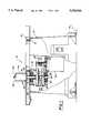
- FIG. 1is a partial cross-section side view of a first embodiment of the oscillating spindle sander
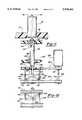
- FIG. 2is a partial cross-sectional end view
- FIG. 4is a top view of the upper cam pulley
- FIG. 6is a cross-sectional front view of the upper cam pulley
- FIG. 7is a top view of the lower drum washer
- FIG. 8is a side view of the lower drum washer
- FIG. 9is a partial side view showing the position of the drive belt when the upper cam pulley is displaced to its uppermost position
- FIG. 10is a partial side view showing the position of the drive belt when the upper cam pulley is displaced to its lowermost position
- FIG. 11is a partial cross-sectional side view of an alternate embodiment of the oscillating spindle sander
- FIG. 12is a partial cross-section showing an alternate embodiment of the oscillating mechanism.
- FIG. 13is a partial side view showing an alternate embodiment having one cam surface engaged by a cam followers.
- the oscillating spindle sander 10has an enclosed cabinet 12 mountable to a top surface 14 of a table or bench as is known in the art.
- a work support platform or work table 16is attached to the top of the enclosed cabinet 12 using a plurality of fasteners such as screws 18.
- An internal frame 20is attached to the underside of the work table 16, as shown in FIG. 2, and supports an electric motor 22 and the lower end of a spindle 24.
- This internal frame 20is preferably made from a structural plastic but may be a metal casting or any other type of support structure known in the art.
- the vertically oriented spindle 24is rotatably supported by the internal frame 20 at its lower end by a lower bearing 26 and at an intermediate location by an upper bearing 28.
- the upper bearing 28is mounted in an upper bearing plate 30 mounted to the inner housing 20 as shown in FIG. 2.
- the inner housinghas a plurality of mounting posts, such as post 32, to which the upper bearing plate 30 is attached.
- a sanding drum 34is attached to the top end of the spindle 24 between a pair of drum washers 36 and 38 by a nut 40.
- the upper end 42 of the spindle 24is threaded to receive nut 40 and has an annular shoulder 44 which forms a seat for drum washer 38.
- a pair of annular grooves 46 and 48are provided in the spindle 24 intermediate the annular shoulder 44 and a lower end 50. These annular grooves receive C-rings 52 and 54, respectively, axially retaining the location of an upper cam pulley 56 to the spindle 24 so that the spindle 24 will be axially displaced with an axial displacement of the upper cam pulley 56 by a lower cam pulley 58 as shall be explained hereinafter.
- the spindle 24also has a key slot 60 provided intermediate the annular grooves 46 and 48 which receives a key 62 as shown in FIG. 2.
- the key 62is also received in a key slot 64 provided in the upper cam pulley 56 as shown in FIG. 4 and rotatably connects the spindle 24 to the upper cam pulley 56.
- a lower cam pulley spacer 66is disposed between the lower cam pulley 58 and the inner race of bearing 26 fixedly locating the lower cam pulley 58 relative to the internal frame 20.
- a coil spring 68circumscribes the spindle 24 between a spring guide 70 and spring seat 72.
- the coil spring 68resiliently biases the spring guide 72 against the inner race of the upper bearing 28 and the spring seat 72 against an upper surface of the upper cam pulley 56.
- the force produced by the spring 68resiliently biases a cam surface of the upper cam pulley 56 against a facing cam surface of the lower cam pulley 58, the lower cam pulley against lower cam pulley spacer 66, and the lower cam pulley spacer 66 against the race of lower bearing 26.
- the coil spring 68also produces a downward force preventing the sanding drum 34 from being stuck in the "up" position during use.
- the details of the upper cam pulley 56are shown in FIGS. 4, 5 and 6.
- the upper cam pulley 56is preferably a structural plastic molding having a mounting bore 74 sized to be slidably received on the spindle 24, a toothed rim 76 and an annular cam surface 78 intermediate the mounting bore 74 and the toothed rim 76.
- the cam surface 78has a sinusoidal contour with two diametrically opposed lobes 80 and 84 as shown in FIG. 5 and two diametrically disposed valleys 82 and 86 spaced 90° from the lobes 80 and 84 as shown in FIG. 6.
- the upper cam pulley 56has a key slot 64 in which is received the key 62 which fixedly connects the upper cam pulley to the spindle 24.
- the toothed rim 76has a predetermined -number of teeth 88 which are engaged by a toothed pulley belt 90 connecting the upper cam pulley 56 to a drive pulley 92 rotatably driven by the electric motor 22.
- the drive pulley 92has a set of elongated teeth 94 which extend its axial length.
- the structure of the lower cam pulley 58is substantially the same as the upper cam pulley 56 with the following differences.
- the lower cam pulley 58does not have or require a key slot such as key slot 64, the amplitude of the sinusoidal contour of its annular cam surface is different from the amplitude of the sinusoidal contour of the annular cam surface 78 of the upper cam pulley 56 and the number of teeth 88 in its toothed rim 76 are different from the number of teeth 88 in the toothed rim 76 of the upper cam pulley 56.
- the lower cam pulley 58is connected to drive pulley 92 by a toothed pulley belt 96.
- the lower cam pulley 58is mounted on the spindle 24 with its cam surface 78 face-to-face with the cam surface of the upper cam pulley 56.
- both the upper and lower cam pulleysare rotated by the common drive pulley 92 and the number of teeth 88 in the toothed rim 76 of the upper cam pulley 56 is different from the number of teeth in the toothed rim of lower cam pulley 58, the upper and lower cam pulleys will rotate at a different speed of rotation as they are simultaneously rotated by the rotation of the drive pulley 92.
- This difference in the rotational speeds of the upper and lower cam pulleyscauses the two cam surfaces to be rotated relative to each other.
- the relative rotation between the face-to-face sinusoidal cam surfacescauses the upper cam pulley 56 to be axially displaced relative to the lower cam pulley 58.
- the amplitude of the axial displacementwill reach a maximum value when the lobes on the cam surface 78 of the upper cam pulley 56 are aligned on the lobes of the cam surface 78 of the lower cam pulley 58 and will reach a minimum value when the lobes on the cam surfaces 78 of the upper and lower cam pulleys are aligned with the valleys.
- the upper cam pulleyhas 70 teeth while the lower cam pulley has only 69 teeth. Because of the difference in the number of teeth in the upper and lower pulleys, there may be a slight difference in their respective diameters. Therefore, to maintain a proper tension on pulley belts 90 or 96, an idler, not shown, may be used.
- the amplitudes of the annular sinusoidal cam surfaces 78 on the upper and lower cam pulleys 56 and 58, respectively,are different.
- the amplitude of the sinusoidal cam surface 78 on the lower cam pulleyis greater than the amplitude of the sinusoidal cam surface of the upper cam pulley to prevent compacting of the sanding dust in the valleys of the cam surface 78 of the lower cam pulley 58. As shown in FIG.
- the amplitude of the sinusoidal cam surface of the lower cam pulley 58is between 16 and 20 millimeters (0.7 inches) while the amplitude of the cam surface of the upper cam pulley 56 is between 10 and 18 millimeters (0.625 inches).
- the upper and lower cam pulleysare preferably made from plastic materials, such as nylon®, teflon® or KelF® which are structurally rigid and have natural slippery surfaces.
- the upper and lower cam pulleysmay be made from a metal and the cam surfaces coated with teflon® or KelF®.
- the spring 68maintains the cam followers 160 in contact with the sinusoidal cam surface 78 of the lower cam pulley.
- the cam followers 160may be provided on the lower cam pulley 58 and engage the sinusoidal cam surface 78 provided on the upper cam pulley 56.
- the drum washer 38 supporting the lower end of sanding drum 34has a plurality of radially extending fins 98, as shown in FIGS. 7 and 8, which cause the washer 38 to function as a centrifugal fan 100 expelling the sanding dust from the region adjacent to spindle 24.
- This centrifugal fan 100produces an air flow from inside the enclosed cabinet 12 into a dust exhaust manifold 102 formed in the lower surface of the work table 10 as shown in FIG. 1.
- a vacuummay also be connected to the dust exhaust manifold for maximum dust extraction efficiency.
- the radial fins 98may be formed by staking, by stamping or any other method known in the art.
- the formation of the radial fins 98 by staking or stampingpreferably produces a non-smooth surface on the drum washer 38 on the side opposite the radial fins which aids in preventing the sanding drum 34 from slipping or rotating relative to the drum washer.
- the axial length of the teeth 88 on the upper cam pulleyis longer than the width of the pulley belt 90 so that the vertical displacement of the pulley belt 90 is less than the vertical displacement of the upper cam pulley 56 as illustrated in FIGS. 9 and 10.
- the pulley belt 90will engage the lower portion of the teeth 88 of the toothed rim 76.
- the pulley belt 90will be displaced to the upper portion of the toothed rim 76.
- the axial displacement of the pulley belt 90 on the drive pulley 92will be less than the axial displacement or amplitude of the upper cam pulley. This reduction in the axial displacement of the pulley belt along the drive pulley 92 significantly reduces the wear of the pulley belt and extends its life.
- FIG. 11An alternate mechanism for oscillating the spindle of an oscillating spindle sander is shown in FIG. 11.
- a hollow spindle guide 98is rotatably mounted to the internal frame members 100 and 102 of the cabinet 10 by bearings 104 and 106, and a spindle 108 rotatably mounted inside the hollow spindle guide 98 by bearings 110 and 112.
- the bearings 110 and 112permit the spindle 108 to be displaced axially with respect to the spindle guide 98 as well as to rotate relative thereto.
- the bearingsmay be ball bearings, needle bearings, bronze bushings or plastic bushings as is known in the art.
- a guide pulley 114is fixedly attached to the spindle guide 98 and rotates therewith and a spindle pulley 116 is fixedly attached to the lower end of the spindle 108.
- the guide pulley 114is connected to a first drive pulley 118 by a pulley belt 120 and the spindle pulley 116 is connected to a second drive pulley 122 by a pulley belt 124.
- the first and second drive pulleys 118 and 122, respectively,are connected to a rotary output shaft 126 of an electric motor 128.
- the diameters of the guide pulley 114 and the spindle pulley 116are different and the diameters of the first and second drive pulleys 120 and 124 are substantially the same so that the guide and spindle pulley 114 and 116 rotate at different rates of speed when rotated by the first and second drive pulleys.
- the guide and spindle pulleys 114 and 116, respectivelymay have substantially the same diameter and the first and second drive pulley 120 and 124, respectively, may have different diameters which also would produce a rotation of the guide pulley 14 relative to the spindle pulley 116 when rotated by the first and second drive pulley 116 and 120, respectively.
- the spindle pulley 116has a cylindrical hub 130 on the side facing the guide pulley 114 which has an annular cam groove having a predetermined contour provided therein.
- the annular cam groovehas a sinusoidal contour having two diametrically opposed peaks 134 and two diametrically opposed valleys 136, but may have more than two diametrically opposed peaks 134 and grooves 136.
- At least one cam follower 138is connected to the guide pulley 114.
- the cam follower 138has a finger 140 which is slidably received in the cam groove 132.
- a second cam follower 142is connected to the guide pulley 114 diametrically opposite cam flowers 138 which also has a finger 144 slidably received in the cam groove 132 at a location diametrically opposite cam follower 138.
- the second cam follower 140counterbalances the torque produced on the spindle pulley 116 produced by cam follower 138 and reduces the wear on bearing 112.
- a pair of retainer rings 146 and 148received in grooves provided in the spindle guide 98 on opposite sides of internal frame member 102, inhibit its axial movement.
- the guide pulley 114 and the spindle pulley 116will rotate relative to each other.
- the fingers 140 and 144 of cam followers 138 and 142respectively, following the sinusoidal contour of cam groove 132 producing an oscillatory displacement spindle pulley 116.
- the oscillatory displacement of the spindle pulley 116oscillates the spindle 108 and the sanding drum 34 relative to the cabinet's work table 16.
- the bottom washer 38 supporting the sanding drum 34may have fins 98 producing an air flow away from the spindle 108.
- the guide pulley 114'may alternatively have a cylindrical hub 150 which has an annular sinusoidal cam groove 152 corresponding to cam groove 132.
- the spindle pulley 116has a cylindrical extension 154 which circumscribes the hub 150.
- a pair of cam follower fingers 156 and 158are attached to the cylindrical extension 154 at diametrically opposed locations and are slidably received in the sinusoidal cam groove 152.
- the cam follower fingers 156 and 158will follow the contour of the sinusoidal cam groove 152 and will axially oscillate the spindle pulley 116 and the attached spindle 108.
Landscapes
- Engineering & Computer Science (AREA)
- Mechanical Engineering (AREA)
- Finish Polishing, Edge Sharpening, And Grinding By Specific Grinding Devices (AREA)
- Grinding And Polishing Of Tertiary Curved Surfaces And Surfaces With Complex Shapes (AREA)
- Constituent Portions Of Griding Lathes, Driving, Sensing And Control (AREA)
- Grinding-Machine Dressing And Accessory Apparatuses (AREA)
Abstract
Description
Claims (13)
Priority Applications (2)
| Application Number | Priority Date | Filing Date | Title |
|---|---|---|---|
| US08/366,977US5558566A (en) | 1993-03-17 | 1994-12-30 | Oscillating spindle sander |
| US08/717,925US5860852A (en) | 1993-03-17 | 1996-09-23 | Oscillating spindle sander |
Applications Claiming Priority (2)
| Application Number | Priority Date | Filing Date | Title |
|---|---|---|---|
| US08/048,326US5402604A (en) | 1993-03-17 | 1993-03-17 | Oscillating spindle sander |
| US08/366,977US5558566A (en) | 1993-03-17 | 1994-12-30 | Oscillating spindle sander |
Related Parent Applications (1)
| Application Number | Title | Priority Date | Filing Date |
|---|---|---|---|
| US08/048,326DivisionUS5402604A (en) | 1993-03-17 | 1993-03-17 | Oscillating spindle sander |
Related Child Applications (1)
| Application Number | Title | Priority Date | Filing Date |
|---|---|---|---|
| US08/717,925ContinuationUS5860852A (en) | 1993-03-17 | 1996-09-23 | Oscillating spindle sander |
Publications (1)
| Publication Number | Publication Date |
|---|---|
| US5558566Atrue US5558566A (en) | 1996-09-24 |
Family
ID=21953968
Family Applications (4)
| Application Number | Title | Priority Date | Filing Date |
|---|---|---|---|
| US08/048,326Expired - Fee RelatedUS5402604A (en) | 1993-03-17 | 1993-03-17 | Oscillating spindle sander |
| US08/368,031Expired - Fee RelatedUS5624302A (en) | 1993-03-17 | 1994-12-30 | Oscillating spindle sander |
| US08/366,977Expired - LifetimeUS5558566A (en) | 1993-03-17 | 1994-12-30 | Oscillating spindle sander |
| US08/717,925Expired - Fee RelatedUS5860852A (en) | 1993-03-17 | 1996-09-23 | Oscillating spindle sander |
Family Applications Before (2)
| Application Number | Title | Priority Date | Filing Date |
|---|---|---|---|
| US08/048,326Expired - Fee RelatedUS5402604A (en) | 1993-03-17 | 1993-03-17 | Oscillating spindle sander |
| US08/368,031Expired - Fee RelatedUS5624302A (en) | 1993-03-17 | 1994-12-30 | Oscillating spindle sander |
Family Applications After (1)
| Application Number | Title | Priority Date | Filing Date |
|---|---|---|---|
| US08/717,925Expired - Fee RelatedUS5860852A (en) | 1993-03-17 | 1996-09-23 | Oscillating spindle sander |
Country Status (3)
| Country | Link |
|---|---|
| US (4) | US5402604A (en) |
| JP (1) | JP2747418B2 (en) |
| DE (1) | DE4408198A1 (en) |
Cited By (4)
| Publication number | Priority date | Publication date | Assignee | Title |
|---|---|---|---|---|
| US6569002B2 (en) | 1999-12-10 | 2003-05-27 | Porter-Cable/Delta | Hand-held oscillating spindle sander |
| US20040103490A1 (en)* | 2002-12-03 | 2004-06-03 | Long David C. | Powered cleaner/polisher |
| US6758731B2 (en) | 2001-08-10 | 2004-07-06 | One World Technologies Limited | Orbital sander |
| US20080029134A1 (en)* | 2003-11-26 | 2008-02-07 | Long David C | Powered cleaner/polisher |
Families Citing this family (32)
| Publication number | Priority date | Publication date | Assignee | Title |
|---|---|---|---|---|
| US5549507A (en)* | 1994-04-26 | 1996-08-27 | Emerson Electric Co. | Combined motor and mechanical drive for use in oscillating spindle sander |
| US5916014A (en)* | 1994-04-26 | 1999-06-29 | Emerson Special Products Division | Oscillating belt/spindle sander |
| US6102787A (en)* | 1994-04-26 | 2000-08-15 | Emerson Electric Co. | Oscillating combination belt, spindle and edge sander |
| USD363291S (en) | 1994-11-03 | 1995-10-17 | Emerson Electric Co. | Oscillating spindle sander |
| US5649852A (en)* | 1995-11-06 | 1997-07-22 | Zepp; Philip H. | Sanding apparatus |
| USD377180S (en)* | 1996-03-07 | 1997-01-07 | Delta International Machinery Corp. | Spindle sanding machine |
| US6419643B1 (en) | 1998-04-21 | 2002-07-16 | Alsius Corporation | Central venous catheter with heat exchange properties |
| USD411549S (en) | 1998-07-09 | 1999-06-29 | Delta International Machinery Corp. | Sanding machine |
| USD423021S (en)* | 1998-12-02 | 2000-04-18 | Emerson Electric, Co. | Edge belt/spindle sander |
| US6948412B2 (en)* | 2003-06-05 | 2005-09-27 | One World Technologies Ltd. | Motor driven wood working tool with vacuum feature |
| US7044843B1 (en)* | 2005-05-09 | 2006-05-16 | Kun Yi Lin | Sander device having vacuuming structure |
| US20080268755A1 (en)* | 2005-06-30 | 2008-10-30 | Dreyer Mark G | Motorized Tool and Support Table Therefore |
| JP4611900B2 (en)* | 2006-01-12 | 2011-01-12 | 株式会社ニックス | Dust removal equipment |
| US20090280733A1 (en)* | 2008-05-08 | 2009-11-12 | Mao Shan Machinery Industrial Co., Ltd | Assembly/disassembly structure of upstanding grinding axle |
| IT1400151B1 (en)* | 2010-05-20 | 2013-05-17 | Mattia Di | WHEEL HANDLING DEVICE. |
| ITRM20100265A1 (en)* | 2010-05-20 | 2011-11-21 | Mattia Mauro Di | WHEEL HANDLING DEVICE. |
| US20120115404A1 (en)* | 2010-11-09 | 2012-05-10 | Frank Alison Houghton | Handheld, Portable Drum Sander |
| USD712852S1 (en) | 2012-03-20 | 2014-09-09 | Veeco Instruments Inc. | Spindle key |
| USD726133S1 (en) | 2012-03-20 | 2015-04-07 | Veeco Instruments Inc. | Keyed spindle |
| US9816184B2 (en) | 2012-03-20 | 2017-11-14 | Veeco Instruments Inc. | Keyed wafer carrier |
| JP2014027006A (en)* | 2012-07-24 | 2014-02-06 | Disco Abrasive Syst Ltd | Processing method of wafer |
| CN102785140A (en)* | 2012-09-10 | 2012-11-21 | 湖南宇环同心数控机床有限公司 | Flexible profile-following constant-pressure polishing device |
| PL3085491T3 (en)* | 2015-04-24 | 2017-09-29 | Arku Maschinenbau Gmbh | Device for grinding and deburring of a planar workpiece |
| CN104942663B (en)* | 2015-07-01 | 2017-07-11 | 嘉兴学院 | Hyperbolic disk grinding crowned roller processing unit (plant) and processing method under ultrasonication |
| CN107116431B (en)* | 2017-04-24 | 2019-01-25 | 温州职业技术学院 | Ultra-precision four-axis smoothing system for intelligent communication terminals |
| CN107775470A (en)* | 2017-06-19 | 2018-03-09 | 义乌市摩亚光电科技有限公司 | A kind of processing sanding apparatus of equidistant rectangle steel bar |
| CN110587388A (en)* | 2019-09-25 | 2019-12-20 | 江苏东巨机械科技有限公司 | Numerical control knife sharpener capable of adjusting height of knife stone |
| CN111390744B (en)* | 2020-03-27 | 2021-07-13 | 浙江恒立金属科技有限公司 | Dustless burnishing device of metal product |
| CN111890111A (en)* | 2020-06-24 | 2020-11-06 | 湖州吴兴双德输送机械有限公司 | Part taking and deslagging device for mechanical part machining equipment |
| CN112548821A (en)* | 2020-12-04 | 2021-03-26 | 湖南宇晶机器股份有限公司 | Lifting mechanism of peripheral polishing machine |
| CN113977441B (en)* | 2021-11-15 | 2022-08-23 | 九江市杰尼新材料有限公司 | Double-sided polishing machine capable of automatically compressing and used for processing electronic element |
| CN117655823B (en)* | 2024-01-31 | 2024-04-09 | 扬州群发光芯科技有限公司 | OPA chip terminal surface ultrasonic polishing system |
Citations (20)
| Publication number | Priority date | Publication date | Assignee | Title |
|---|---|---|---|---|
| SU220086A1 (en)* | В. А. Гно ник , М. П. Кузнецова | THE DEVICE FOR VIBRATION TREATMENT OF DETAILS OF THE TYPE OF HOSE OF TRACTOR ENGINES | ||
| US130420A (en)* | 1872-08-13 | Improvement in sand-papering machines | ||
| US137465A (en)* | 1873-04-01 | Improvement in buffing-machines | ||
| US1477158A (en)* | 1921-04-02 | 1923-12-11 | Charles H Lea | Grinding machine |
| US1662137A (en)* | 1924-03-04 | 1928-03-13 | Bethelplayer Co | Lapping machine |
| US1701815A (en)* | 1926-09-10 | 1929-02-12 | William J Maddox | Spindle sanding machine |
| US1849868A (en)* | 1923-11-08 | 1932-03-15 | Cincinnati Milling Machine Co | Grinder wheel oscillator |
| US2105762A (en)* | 1935-12-05 | 1938-01-18 | Bower Roller Bearing Co | Machine for honing conical surfaces |
| US2236232A (en)* | 1938-09-03 | 1941-03-25 | Western Electric Co | Exhausting apparatus |
| US2252176A (en)* | 1936-12-19 | 1941-08-12 | Micromatic Hone Corp | Machine for grinding cylindrical surfaces |
| US2323433A (en)* | 1937-08-13 | 1943-07-06 | Micromatic Hone Corp | Fluid actuated head for abrading elements |
| US2426028A (en)* | 1945-04-16 | 1947-08-19 | Adolph F Krueger | Sanding machine |
| US2484471A (en)* | 1947-12-26 | 1949-10-11 | Charles A Shinn | Hammer drill |
| US2521900A (en)* | 1945-09-01 | 1950-09-12 | Western Electric Co | Chip breaking device |
| US2836937A (en)* | 1956-04-09 | 1958-06-03 | Richard T Cornelius | Motor driven grinders |
| US2979962A (en)* | 1958-08-15 | 1961-04-18 | John E Nindel | Percussion attachments for rotary drills |
| US3037328A (en)* | 1959-11-19 | 1962-06-05 | Dykrex Corp | Lapping tool |
| US3886789A (en)* | 1971-12-27 | 1975-06-03 | Donald W Brookfield | Viscometer |
| US4397055A (en)* | 1980-10-20 | 1983-08-09 | Cuchiara Samuel M | Reversable shaft with rotary and selective oscillating motion |
| US4529044A (en)* | 1983-03-28 | 1985-07-16 | Hilti Aktiengesellschaft | Electropneumatic hammer drill or chipping hammer |
Family Cites Families (4)
| Publication number | Priority date | Publication date | Assignee | Title |
|---|---|---|---|---|
| US2114343A (en)* | 1937-05-28 | 1938-04-19 | Boyer Schultz Corp | Grinding machine |
| US2242781A (en)* | 1940-01-24 | 1941-05-20 | Boyar Schultz Corp | Grinding machine |
| JPS63158762U (en)* | 1987-04-01 | 1988-10-18 | ||
| US5042202A (en)* | 1989-12-13 | 1991-08-27 | Kadia-Maschinenbau Kopp Gmbh & Co. | Brush-honing machine |
- 1993
- 1993-03-17USUS08/048,326patent/US5402604A/ennot_activeExpired - Fee Related
- 1994
- 1994-03-08JPJP6037168Apatent/JP2747418B2/ennot_activeExpired - Fee Related
- 1994-03-11DEDE4408198Apatent/DE4408198A1/ennot_activeWithdrawn
- 1994-12-30USUS08/368,031patent/US5624302A/ennot_activeExpired - Fee Related
- 1994-12-30USUS08/366,977patent/US5558566A/ennot_activeExpired - Lifetime
- 1996
- 1996-09-23USUS08/717,925patent/US5860852A/ennot_activeExpired - Fee Related
Patent Citations (20)
| Publication number | Priority date | Publication date | Assignee | Title |
|---|---|---|---|---|
| US130420A (en)* | 1872-08-13 | Improvement in sand-papering machines | ||
| US137465A (en)* | 1873-04-01 | Improvement in buffing-machines | ||
| SU220086A1 (en)* | В. А. Гно ник , М. П. Кузнецова | THE DEVICE FOR VIBRATION TREATMENT OF DETAILS OF THE TYPE OF HOSE OF TRACTOR ENGINES | ||
| US1477158A (en)* | 1921-04-02 | 1923-12-11 | Charles H Lea | Grinding machine |
| US1849868A (en)* | 1923-11-08 | 1932-03-15 | Cincinnati Milling Machine Co | Grinder wheel oscillator |
| US1662137A (en)* | 1924-03-04 | 1928-03-13 | Bethelplayer Co | Lapping machine |
| US1701815A (en)* | 1926-09-10 | 1929-02-12 | William J Maddox | Spindle sanding machine |
| US2105762A (en)* | 1935-12-05 | 1938-01-18 | Bower Roller Bearing Co | Machine for honing conical surfaces |
| US2252176A (en)* | 1936-12-19 | 1941-08-12 | Micromatic Hone Corp | Machine for grinding cylindrical surfaces |
| US2323433A (en)* | 1937-08-13 | 1943-07-06 | Micromatic Hone Corp | Fluid actuated head for abrading elements |
| US2236232A (en)* | 1938-09-03 | 1941-03-25 | Western Electric Co | Exhausting apparatus |
| US2426028A (en)* | 1945-04-16 | 1947-08-19 | Adolph F Krueger | Sanding machine |
| US2521900A (en)* | 1945-09-01 | 1950-09-12 | Western Electric Co | Chip breaking device |
| US2484471A (en)* | 1947-12-26 | 1949-10-11 | Charles A Shinn | Hammer drill |
| US2836937A (en)* | 1956-04-09 | 1958-06-03 | Richard T Cornelius | Motor driven grinders |
| US2979962A (en)* | 1958-08-15 | 1961-04-18 | John E Nindel | Percussion attachments for rotary drills |
| US3037328A (en)* | 1959-11-19 | 1962-06-05 | Dykrex Corp | Lapping tool |
| US3886789A (en)* | 1971-12-27 | 1975-06-03 | Donald W Brookfield | Viscometer |
| US4397055A (en)* | 1980-10-20 | 1983-08-09 | Cuchiara Samuel M | Reversable shaft with rotary and selective oscillating motion |
| US4529044A (en)* | 1983-03-28 | 1985-07-16 | Hilti Aktiengesellschaft | Electropneumatic hammer drill or chipping hammer |
Non-Patent Citations (3)
| Title |
|---|
| Owners Manual For Clayton Model No. 140, Oscillating Spindle Sander, 1991.* |
| Wood Magazine, Sep. 1994, Oscillating Spindle Sanders under $700 We put them to test, pp. 78 82.* |
| Wood Magazine, Sep. 1994, Oscillating Spindle Sanders under $700 We put them to test, pp. 78-82. |
Cited By (8)
| Publication number | Priority date | Publication date | Assignee | Title |
|---|---|---|---|---|
| US6569002B2 (en) | 1999-12-10 | 2003-05-27 | Porter-Cable/Delta | Hand-held oscillating spindle sander |
| US6758731B2 (en) | 2001-08-10 | 2004-07-06 | One World Technologies Limited | Orbital sander |
| US20050003748A1 (en)* | 2001-08-10 | 2005-01-06 | One World Technologies, Limited | Orbital sander |
| US7270598B2 (en) | 2001-08-10 | 2007-09-18 | Eastway Fair Company Ltd. | Orbital sander |
| US20040103490A1 (en)* | 2002-12-03 | 2004-06-03 | Long David C. | Powered cleaner/polisher |
| US7313838B2 (en) | 2002-12-03 | 2008-01-01 | S.C. Johnson & Son, Inc. | Powered cleaner/polisher |
| US20080029134A1 (en)* | 2003-11-26 | 2008-02-07 | Long David C | Powered cleaner/polisher |
| US7565712B2 (en) | 2003-11-26 | 2009-07-28 | S.C. Johnson & Son, Inc. | Powered cleaner/polisher |
Also Published As
| Publication number | Publication date |
|---|---|
| US5402604A (en) | 1995-04-04 |
| US5860852A (en) | 1999-01-19 |
| JPH0752035A (en) | 1995-02-28 |
| JP2747418B2 (en) | 1998-05-06 |
| DE4408198A1 (en) | 1994-09-22 |
| US5624302A (en) | 1997-04-29 |
Similar Documents
| Publication | Publication Date | Title |
|---|---|---|
| US5558566A (en) | Oscillating spindle sander | |
| US5458533A (en) | Eccentric disk sander | |
| US3857206A (en) | Compound motion rubbing machine | |
| US20040248507A1 (en) | Motor driven wood working tool with vacuum feature | |
| US4242839A (en) | High-speed power tool | |
| US6830501B2 (en) | End face polishing device | |
| CN208231559U (en) | A kind of offset assembly of sander | |
| WO1996005939A1 (en) | Sander vibration isolator | |
| US20070044609A1 (en) | Motor driven wood working tool with vacuum feature | |
| US4332542A (en) | Electrically driven potter's wheel | |
| CN210255702U (en) | High-efficient polishing power bistrique | |
| US4028247A (en) | Vibratory coolant strainer for machine tool coolant systems | |
| US5335560A (en) | Table-top grinder power transmission mechanism | |
| KR930703118A (en) | Machines used to make power steering gears for vehicles | |
| US5916014A (en) | Oscillating belt/spindle sander | |
| US3971167A (en) | Tumbling apparatus | |
| CA2016730A1 (en) | Grinding Wheel for Producing Internal Profilings | |
| CN211193493U (en) | Reciprocating lifting mechanism for sanding machine | |
| US5022157A (en) | Transmission mechanism for scroll sawing machine | |
| CN208100033U (en) | The Burnishing wheel horizontal drive apparatus of water-drill grinding and polishing machine | |
| US5497687A (en) | Table-top cutting machine | |
| CN223000362U (en) | Eccentric fan structure of polishing machine | |
| CN111468990A (en) | Internal combustion engine crankshaft finish machining process | |
| KR960010170A (en) | Bowling ball grinding / cleaning and true ball correction cutting processing device | |
| CN222359978U (en) | A screw polishing machine |
Legal Events
| Date | Code | Title | Description |
|---|---|---|---|
| STCF | Information on status: patent grant | Free format text:PATENTED CASE | |
| AS | Assignment | Owner name:RYOBI NORTH AMERICA, INC., SOUTH CAROLINA Free format text:ASSIGNMENT OF ASSIGNORS INTEREST;ASSIGNOR:RYOBI MOTOR PRODUCTS CORP.;REEL/FRAME:009038/0534 Effective date:19980209 | |
| REMI | Maintenance fee reminder mailed | ||
| AS | Assignment | Owner name:HSBC BANK USA, NEW YORK Free format text:SECURITY INTEREST;ASSIGNORS:ONE WORLD TECHNOLOGIES INC.;RYOBI TECHNOLOGIES, INC.;OWT INDUSTRIES, INC.;REEL/FRAME:011103/0770 Effective date:20000801 | |
| AS | Assignment | Owner name:ONE WORLD TECHNOLOGIES, INC., SOUTH CAROLINA Free format text:ASSIGNMENT OF ASSIGNORS INTEREST;ASSIGNOR:RYOBI NORTH AMERICA, INC.;REEL/FRAME:011149/0407 Effective date:20000731 | |
| FPAY | Fee payment | Year of fee payment:4 | |
| SULP | Surcharge for late payment | ||
| AS | Assignment | Owner name:ONE WORLD TECHNOLOGIES LIMITED, BERMUDA Free format text:ASSIGNMENT OF ASSIGNORS INTEREST;ASSIGNOR:ONE WORLD TECHNOLOGIES, INC.;REEL/FRAME:014066/0731 Effective date:20030512 | |
| FEPP | Fee payment procedure | Free format text:PAYOR NUMBER ASSIGNED (ORIGINAL EVENT CODE: ASPN); ENTITY STATUS OF PATENT OWNER: LARGE ENTITY | |
| FPAY | Fee payment | Year of fee payment:8 | |
| FPAY | Fee payment | Year of fee payment:12 | |
| FEPP | Fee payment procedure | Free format text:PAYOR NUMBER ASSIGNED (ORIGINAL EVENT CODE: ASPN); ENTITY STATUS OF PATENT OWNER: LARGE ENTITY Free format text:PAYER NUMBER DE-ASSIGNED (ORIGINAL EVENT CODE: RMPN); ENTITY STATUS OF PATENT OWNER: LARGE ENTITY |