US5556687A - Composite structure suitable for use as a bone plate and method for making said structure - Google Patents
Composite structure suitable for use as a bone plate and method for making said structureDownload PDFInfo
- Publication number
- US5556687A US5556687AUS08/323,251US32325194AUS5556687AUS 5556687 AUS5556687 AUS 5556687AUS 32325194 AUS32325194 AUS 32325194AUS 5556687 AUS5556687 AUS 5556687A
- Authority
- US
- United States
- Prior art keywords
- reinforcing fibers
- set forth
- composite structure
- bone plate
- braided
- Prior art date
- Legal status (The legal status is an assumption and is not a legal conclusion. Google has not performed a legal analysis and makes no representation as to the accuracy of the status listed.)
- Expired - Fee Related
Links
- 239000002131composite materialSubstances0.000titleclaimsabstractdescription121
- 210000000988bone and boneAnatomy0.000titleclaimsabstractdescription98
- 238000000034methodMethods0.000titleclaimsabstractdescription28
- 239000012783reinforcing fiberSubstances0.000claimsabstractdescription104
- 238000005452bendingMethods0.000claimsabstractdescription11
- 239000011159matrix materialSubstances0.000claimsdescription39
- 238000009954braidingMethods0.000claimsdescription16
- RTAQQCXQSZGOHL-UHFFFAOYSA-NTitaniumChemical compound[Ti]RTAQQCXQSZGOHL-UHFFFAOYSA-N0.000claimsdescription11
- 239000000835fiberSubstances0.000claimsdescription9
- 238000010438heat treatmentMethods0.000claimsdescription6
- 238000004519manufacturing processMethods0.000abstractdescription2
- 229920000049Carbon (fiber)Polymers0.000description7
- 229920004878Ultrapek®Polymers0.000description7
- 239000004917carbon fiberSubstances0.000description7
- 229920000642polymerPolymers0.000description7
- 239000000463materialSubstances0.000description4
- 208000010392Bone FracturesDiseases0.000description3
- 239000003550markerSubstances0.000description3
- CSCPPACGZOOCGX-UHFFFAOYSA-NAcetoneChemical compoundCC(C)=OCSCPPACGZOOCGX-UHFFFAOYSA-N0.000description2
- OKTJSMMVPCPJKN-UHFFFAOYSA-NCarbonChemical compound[C]OKTJSMMVPCPJKN-UHFFFAOYSA-N0.000description2
- 101100084040Neurospora crassa (strain ATCC 24698 / 74-OR23-1A / CBS 708.71 / DSM 1257 / FGSC 987) ppi-1 geneProteins0.000description2
- 239000000560biocompatible materialSubstances0.000description2
- 229910052799carbonInorganic materials0.000description2
- 238000007596consolidation processMethods0.000description2
- 239000007943implantSubstances0.000description2
- 238000012986modificationMethods0.000description2
- 230000004048modificationEffects0.000description2
- 229920005594polymer fiberPolymers0.000description2
- 239000010936titaniumSubstances0.000description2
- CAWGQUPKYLTTNX-UHFFFAOYSA-N3,4,5,6-tetrahydro-2,7-benzodioxecine-1,8-dioneChemical compoundO=C1OCCCCOC(=O)C2=CC=CC=C12CAWGQUPKYLTTNX-UHFFFAOYSA-N0.000description1
- SENMPMXZMGNQAG-UHFFFAOYSA-N3,4-dihydro-2,5-benzodioxocine-1,6-dioneChemical compoundO=C1OCCOC(=O)C2=CC=CC=C12SENMPMXZMGNQAG-UHFFFAOYSA-N0.000description1
- 229910001200FerrotitaniumInorganic materials0.000description1
- 229920000106Liquid crystal polymerPolymers0.000description1
- 239000004977Liquid-crystal polymers (LCPs)Substances0.000description1
- 239000004677NylonSubstances0.000description1
- 239000004696Poly ether ether ketoneSubstances0.000description1
- NRTOMJZYCJJWKI-UHFFFAOYSA-NTitanium nitrideChemical compound[Ti]#NNRTOMJZYCJJWKI-UHFFFAOYSA-N0.000description1
- 125000005362aryl sulfone groupChemical group0.000description1
- JUPQTSLXMOCDHR-UHFFFAOYSA-Nbenzene-1,4-diol;bis(4-fluorophenyl)methanoneChemical compoundOC1=CC=C(O)C=C1.C1=CC(F)=CC=C1C(=O)C1=CC=C(F)C=C1JUPQTSLXMOCDHR-UHFFFAOYSA-N0.000description1
- 229920000249biocompatible polymerPolymers0.000description1
- 230000010072bone remodelingEffects0.000description1
- 239000011248coating agentSubstances0.000description1
- 238000000576coating methodMethods0.000description1
- 238000010276constructionMethods0.000description1
- 238000001816coolingMethods0.000description1
- 230000007423decreaseEffects0.000description1
- 230000007850degenerationEffects0.000description1
- 238000006073displacement reactionMethods0.000description1
- 239000003733fiber-reinforced compositeSubstances0.000description1
- 239000003365glass fiberSubstances0.000description1
- 229910002804graphiteInorganic materials0.000description1
- 239000010439graphiteSubstances0.000description1
- 230000035876healingEffects0.000description1
- 238000009434installationMethods0.000description1
- 229910052751metalInorganic materials0.000description1
- 239000002184metalSubstances0.000description1
- 229920001778nylonPolymers0.000description1
- -1poly (amide imideChemical class0.000description1
- 229920001643poly(ether ketone)Polymers0.000description1
- 229920001660poly(etherketone-etherketoneketone)Polymers0.000description1
- 229920001652poly(etherketoneketone)Polymers0.000description1
- 229920002239polyacrylonitrilePolymers0.000description1
- 229920006260polyaryletherketonePolymers0.000description1
- 229920002530polyetherether ketonePolymers0.000description1
- 239000002861polymer materialSubstances0.000description1
- 239000000843powderSubstances0.000description1
- 230000002787reinforcementEffects0.000description1
- HBMJWWWQQXIZIP-UHFFFAOYSA-Nsilicon carbideChemical compound[Si+]#[C-]HBMJWWWQQXIZIP-UHFFFAOYSA-N0.000description1
- 229910010271silicon carbideInorganic materials0.000description1
- 229910001220stainless steelInorganic materials0.000description1
- 239000010935stainless steelSubstances0.000description1
- 210000001519tissueAnatomy0.000description1
- 229910052719titaniumInorganic materials0.000description1
- 238000003325tomographyMethods0.000description1
Images


Classifications
- B—PERFORMING OPERATIONS; TRANSPORTING
- B29—WORKING OF PLASTICS; WORKING OF SUBSTANCES IN A PLASTIC STATE IN GENERAL
- B29C—SHAPING OR JOINING OF PLASTICS; SHAPING OF MATERIAL IN A PLASTIC STATE, NOT OTHERWISE PROVIDED FOR; AFTER-TREATMENT OF THE SHAPED PRODUCTS, e.g. REPAIRING
- B29C70/00—Shaping composites, i.e. plastics material comprising reinforcements, fillers or preformed parts, e.g. inserts
- B29C70/04—Shaping composites, i.e. plastics material comprising reinforcements, fillers or preformed parts, e.g. inserts comprising reinforcements only, e.g. self-reinforcing plastics
- B29C70/06—Fibrous reinforcements only
- B29C70/10—Fibrous reinforcements only characterised by the structure of fibrous reinforcements, e.g. hollow fibres
- B29C70/16—Fibrous reinforcements only characterised by the structure of fibrous reinforcements, e.g. hollow fibres using fibres of substantial or continuous length
- B29C70/22—Fibrous reinforcements only characterised by the structure of fibrous reinforcements, e.g. hollow fibres using fibres of substantial or continuous length oriented in at least two directions forming a two dimensional structure
- B29C70/222—Fibrous reinforcements only characterised by the structure of fibrous reinforcements, e.g. hollow fibres using fibres of substantial or continuous length oriented in at least two directions forming a two dimensional structure the structure being shaped to form a three dimensional configuration
- A—HUMAN NECESSITIES
- A61—MEDICAL OR VETERINARY SCIENCE; HYGIENE
- A61B—DIAGNOSIS; SURGERY; IDENTIFICATION
- A61B17/00—Surgical instruments, devices or methods
- A61B17/56—Surgical instruments or methods for treatment of bones or joints; Devices specially adapted therefor
- A61B17/58—Surgical instruments or methods for treatment of bones or joints; Devices specially adapted therefor for osteosynthesis, e.g. bone plates, screws or setting implements
- A61B17/68—Internal fixation devices, including fasteners and spinal fixators, even if a part thereof projects from the skin
- A61B17/70—Spinal positioners or stabilisers, e.g. stabilisers comprising fluid filler in an implant
- A61B17/7001—Screws or hooks combined with longitudinal elements which do not contact vertebrae
- A61B17/7002—Longitudinal elements, e.g. rods
- A61B17/7004—Longitudinal elements, e.g. rods with a cross-section which varies along its length
- A61B17/7007—Parts of the longitudinal elements, e.g. their ends, being specially adapted to fit around the screw or hook heads
- A—HUMAN NECESSITIES
- A61—MEDICAL OR VETERINARY SCIENCE; HYGIENE
- A61B—DIAGNOSIS; SURGERY; IDENTIFICATION
- A61B17/00—Surgical instruments, devices or methods
- A61B17/56—Surgical instruments or methods for treatment of bones or joints; Devices specially adapted therefor
- A61B17/58—Surgical instruments or methods for treatment of bones or joints; Devices specially adapted therefor for osteosynthesis, e.g. bone plates, screws or setting implements
- A61B17/68—Internal fixation devices, including fasteners and spinal fixators, even if a part thereof projects from the skin
- A61B17/70—Spinal positioners or stabilisers, e.g. stabilisers comprising fluid filler in an implant
- A61B17/7001—Screws or hooks combined with longitudinal elements which do not contact vertebrae
- A61B17/7002—Longitudinal elements, e.g. rods
- A61B17/701—Longitudinal elements with a non-circular, e.g. rectangular, cross-section
- B—PERFORMING OPERATIONS; TRANSPORTING
- B29—WORKING OF PLASTICS; WORKING OF SUBSTANCES IN A PLASTIC STATE IN GENERAL
- B29C—SHAPING OR JOINING OF PLASTICS; SHAPING OF MATERIAL IN A PLASTIC STATE, NOT OTHERWISE PROVIDED FOR; AFTER-TREATMENT OF THE SHAPED PRODUCTS, e.g. REPAIRING
- B29C70/00—Shaping composites, i.e. plastics material comprising reinforcements, fillers or preformed parts, e.g. inserts
- B29C70/04—Shaping composites, i.e. plastics material comprising reinforcements, fillers or preformed parts, e.g. inserts comprising reinforcements only, e.g. self-reinforcing plastics
- B29C70/28—Shaping operations therefor
- B29C70/30—Shaping by lay-up, i.e. applying fibres, tape or broadsheet on a mould, former or core; Shaping by spray-up, i.e. spraying of fibres on a mould, former or core
- B29C70/34—Shaping by lay-up, i.e. applying fibres, tape or broadsheet on a mould, former or core; Shaping by spray-up, i.e. spraying of fibres on a mould, former or core and shaping or impregnating by compression, i.e. combined with compressing after the lay-up operation
- B—PERFORMING OPERATIONS; TRANSPORTING
- B29—WORKING OF PLASTICS; WORKING OF SUBSTANCES IN A PLASTIC STATE IN GENERAL
- B29C—SHAPING OR JOINING OF PLASTICS; SHAPING OF MATERIAL IN A PLASTIC STATE, NOT OTHERWISE PROVIDED FOR; AFTER-TREATMENT OF THE SHAPED PRODUCTS, e.g. REPAIRING
- B29C70/00—Shaping composites, i.e. plastics material comprising reinforcements, fillers or preformed parts, e.g. inserts
- B29C70/88—Shaping composites, i.e. plastics material comprising reinforcements, fillers or preformed parts, e.g. inserts characterised primarily by possessing specific properties, e.g. electrically conductive or locally reinforced
- B29C70/882—Shaping composites, i.e. plastics material comprising reinforcements, fillers or preformed parts, e.g. inserts characterised primarily by possessing specific properties, e.g. electrically conductive or locally reinforced partly or totally electrically conductive, e.g. for EMI shielding
- B29C70/885—Shaping composites, i.e. plastics material comprising reinforcements, fillers or preformed parts, e.g. inserts characterised primarily by possessing specific properties, e.g. electrically conductive or locally reinforced partly or totally electrically conductive, e.g. for EMI shielding with incorporated metallic wires, nets, films or plates
- A—HUMAN NECESSITIES
- A61—MEDICAL OR VETERINARY SCIENCE; HYGIENE
- A61B—DIAGNOSIS; SURGERY; IDENTIFICATION
- A61B17/00—Surgical instruments, devices or methods
- A61B17/56—Surgical instruments or methods for treatment of bones or joints; Devices specially adapted therefor
- A61B17/58—Surgical instruments or methods for treatment of bones or joints; Devices specially adapted therefor for osteosynthesis, e.g. bone plates, screws or setting implements
- A61B17/68—Internal fixation devices, including fasteners and spinal fixators, even if a part thereof projects from the skin
- A61B17/70—Spinal positioners or stabilisers, e.g. stabilisers comprising fluid filler in an implant
- A61B17/7001—Screws or hooks combined with longitudinal elements which do not contact vertebrae
- A61B17/7002—Longitudinal elements, e.g. rods
- A61B17/7011—Longitudinal element being non-straight, e.g. curved, angled or branched
- A—HUMAN NECESSITIES
- A61—MEDICAL OR VETERINARY SCIENCE; HYGIENE
- A61B—DIAGNOSIS; SURGERY; IDENTIFICATION
- A61B17/00—Surgical instruments, devices or methods
- A61B2017/00526—Methods of manufacturing
- A—HUMAN NECESSITIES
- A61—MEDICAL OR VETERINARY SCIENCE; HYGIENE
- A61B—DIAGNOSIS; SURGERY; IDENTIFICATION
- A61B17/00—Surgical instruments, devices or methods
- A61B2017/00831—Material properties
- A—HUMAN NECESSITIES
- A61—MEDICAL OR VETERINARY SCIENCE; HYGIENE
- A61B—DIAGNOSIS; SURGERY; IDENTIFICATION
- A61B90/00—Instruments, implements or accessories specially adapted for surgery or diagnosis and not covered by any of the groups A61B1/00 - A61B50/00, e.g. for luxation treatment or for protecting wound edges
- A61B90/39—Markers, e.g. radio-opaque or breast lesions markers
- B—PERFORMING OPERATIONS; TRANSPORTING
- B29—WORKING OF PLASTICS; WORKING OF SUBSTANCES IN A PLASTIC STATE IN GENERAL
- B29L—INDEXING SCHEME ASSOCIATED WITH SUBCLASS B29C, RELATING TO PARTICULAR ARTICLES
- B29L2031/00—Other particular articles
- B29L2031/753—Medical equipment; Accessories therefor
- B29L2031/7532—Artificial members, protheses
- Y—GENERAL TAGGING OF NEW TECHNOLOGICAL DEVELOPMENTS; GENERAL TAGGING OF CROSS-SECTIONAL TECHNOLOGIES SPANNING OVER SEVERAL SECTIONS OF THE IPC; TECHNICAL SUBJECTS COVERED BY FORMER USPC CROSS-REFERENCE ART COLLECTIONS [XRACs] AND DIGESTS
- Y10—TECHNICAL SUBJECTS COVERED BY FORMER USPC
- Y10S—TECHNICAL SUBJECTS COVERED BY FORMER USPC CROSS-REFERENCE ART COLLECTIONS [XRACs] AND DIGESTS
- Y10S428/00—Stock material or miscellaneous articles
- Y10S428/902—High modulus filament or fiber
- Y—GENERAL TAGGING OF NEW TECHNOLOGICAL DEVELOPMENTS; GENERAL TAGGING OF CROSS-SECTIONAL TECHNOLOGIES SPANNING OVER SEVERAL SECTIONS OF THE IPC; TECHNICAL SUBJECTS COVERED BY FORMER USPC CROSS-REFERENCE ART COLLECTIONS [XRACs] AND DIGESTS
- Y10—TECHNICAL SUBJECTS COVERED BY FORMER USPC
- Y10S—TECHNICAL SUBJECTS COVERED BY FORMER USPC CROSS-REFERENCE ART COLLECTIONS [XRACs] AND DIGESTS
- Y10S623/00—Prosthesis, i.e. artificial body members, parts thereof, or aids and accessories therefor
- Y10S623/901—Method of manufacturing prosthetic device
- Y—GENERAL TAGGING OF NEW TECHNOLOGICAL DEVELOPMENTS; GENERAL TAGGING OF CROSS-SECTIONAL TECHNOLOGIES SPANNING OVER SEVERAL SECTIONS OF THE IPC; TECHNICAL SUBJECTS COVERED BY FORMER USPC CROSS-REFERENCE ART COLLECTIONS [XRACs] AND DIGESTS
- Y10—TECHNICAL SUBJECTS COVERED BY FORMER USPC
- Y10T—TECHNICAL SUBJECTS COVERED BY FORMER US CLASSIFICATION
- Y10T428/00—Stock material or miscellaneous articles
- Y10T428/24—Structurally defined web or sheet [e.g., overall dimension, etc.]
- Y10T428/24058—Structurally defined web or sheet [e.g., overall dimension, etc.] including grain, strips, or filamentary elements in respective layers or components in angular relation
- Y10T428/24124—Fibers
- Y—GENERAL TAGGING OF NEW TECHNOLOGICAL DEVELOPMENTS; GENERAL TAGGING OF CROSS-SECTIONAL TECHNOLOGIES SPANNING OVER SEVERAL SECTIONS OF THE IPC; TECHNICAL SUBJECTS COVERED BY FORMER USPC CROSS-REFERENCE ART COLLECTIONS [XRACs] AND DIGESTS
- Y10—TECHNICAL SUBJECTS COVERED BY FORMER USPC
- Y10T—TECHNICAL SUBJECTS COVERED BY FORMER US CLASSIFICATION
- Y10T428/00—Stock material or miscellaneous articles
- Y10T428/24—Structurally defined web or sheet [e.g., overall dimension, etc.]
- Y10T428/24273—Structurally defined web or sheet [e.g., overall dimension, etc.] including aperture
- Y10T428/24298—Noncircular aperture [e.g., slit, diamond, rectangular, etc.]
- Y10T428/24314—Slit or elongated
Definitions
- the present inventionrelates to a composite structure, and in particular relates to a composite structure comprising matrix material with braided reinforcing fibers and a method of making the structure.
- a known composite structurecomprises a laminated stack of layers of matrix material containing linearly oriented reinforcing fibers. The direction of orientation of the reinforcing fibers in one layer may be at a different angle relative to the direction of orientation of the reinforcing fibers in an adjacent layer.
- a disadvantage of a laminated stack of layers of a matrix material containing linearly oriented reinforcing fibersis that there is no fiber reinforcement in a direction perpendicular to the layers.
- a known way to strengthen the structure in the direction perpendicular to the layersis to stitch the layers together. A disadvantage in stitching the layers together is that the stitching process is labor and equipment intensive.
- known fiber reinforced composite structuresare made from knitted fibers and woven fibers which form a three-dimensional structure. However, the making of these composite structures is also labor and equipment intensive.
- a composite structureis made by a method which comprises the steps of braiding reinforcing fibers of a radially inner portion of a preform to extend substantially transverse to an axis of the preform along which the composite structure is subject to splitting. Reinforcing fibers of a radially outer portion circumscribing the radially inner portion are braided to extend substantially parallel to the axis of the preform.
- the preformis placed in a mold and heated to a temperature at which fibers which are to become the matrix material melt but the reinforcing fibers do not melt.
- the preformis consolidated in the mold. After heating and consolidating the preform, the composite structure is cooled so that a device such as a bone plate can be machined from the composite structure.
- the composite structurecomprises a radially inner portion of matrix material with braided reinforcing fibers extending throughout the inner portion substantially transverse to an axis of the composite structure along which the composite structure is subject to splitting to resist splitting of the composite structure.
- a radially outer portion of matrix materialcircumscribes the inner portion and has braided reinforcing fibers extending throughout the outer portion substantially parallel to the axis to resist bending of the composite structure.
- the composite structureis similar to an I-beam in bending.
- the radially outer portionslike the outer webs of an I-beam, need the strength to resist bending of the composite structure because the stresses due to the bending are concentrated in the radially outer portions.
- the radially inner portionlike the connecting web of the I-beam, does not need to resist bending.
- the radially inner portioncan be used to resist splitting of the composite structure.
- the composite structureis machined into a bone plate for maintaining adjacent bone members, such as vertebrae or pieces of a broken bone, in a desired spatial relationship.
- adjacent bone memberssuch as vertebrae or pieces of a broken bone
- the bone plateis subjected to clamping forces which could cause the bone plate to split along an axis.
- the braided reinforcing fibers in the radially inner portion of matrix materialresist splitting of the bone plate due to the clamping forces applied to the bone plate by the fasteners.
- the braided reinforcing fibers extending through the radially outer portionresist bending of the bone plate and prevent movement between adjacent bone members which the bone plate is connected to.
- a composite bone plateas compared to a metal bone plate, is advantageous because it does not block the image of tissue on X-ray films and computerized tomography scans. A doctor can easily see if the pieces of a broken bone to which the composite bone plate is connected are healing properly or if adjacent vertebrae to which the composite bone plate is connected are fusing together properly.
- An X-ray markersuch as a titanium wire, may be braided into the composite bone plate so that a doctor may determine the position of the bone plate.
- the stress-strain curve for bonehas an initial region where some strain is achieved with very little stress. This initial region of the stress-strain curve is often called the "toe" of the stress-strain curve. At higher stresses, the curve becomes linear or proportional. The "toe" region allows for some deformation of the bone at low stress levels, while becoming more rigid at higher stresses, protecting against higher loads. The low stress deformation of bone is important in bone remodeling since the bone remodels to support applied loads.
- the composite structure of the present inventionis well suited for use as a bone plate since it can be made to have a stress-strain curve similar to that of bone, that is, with a low-stress "toe" region.
- Contorted reinforcing fibersmay be used in the composite structure to increase the size of the "toe" region. Twisted commingled yarn may be used in braiding the preform or the reinforcing fibers may be coiled, wavy, or kinked. With these structures, the matrix material of the bone plate deforms at low stress levels while the reinforcing fibers begin to straighten out. At higher stress levels, the reinforcing fibers straighten out to pick up the load and the composite plate becomes stiffer.
- FIG. 1is a fragmentary view of a portion of a spinal column on which a composite bone plate constructed in accordance with the present invention has been installed to maintain vertebrae in a desired spatial relationship;
- FIG. 2is a sectional view, taken generally along the line 2--2 of FIG. 1, illustrating the manner in which fasteners are used to connect the composite bone plate with the vertebrae;
- FIG. 3is a plan view of the composite bone plate of FIG. 1;
- FIG. 4is a sectional view of the composite bone plate of FIG. 3 taken along the line 4--4 of FIG. 3;
- FIG. 5is a schematic view of a preform, partially cut away to show various layers of the preform, used in forming the composite bone plate of FIG. 1;
- FIG. 6is an enlarged plan view of a portion of a layer of the preform of FIG. 5;
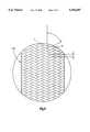
- FIG. 7is a schematic perspective view of a composite structure, partially cut away to show various portions of the structure, from which the bone plate of FIG. 1 is machined;
- FIG. 8is a graph showing the relationship between stress and strain for the composite structure of FIG. 7.
- a pair of surgically implantable composite bone plates 10for correcting deformation and/or degeneration of a spinal column C are connected with several vertebrae V of the spinal column by fasteners 20.
- Each composite bone plate 10is elongate and has a rectangular cross-section taken in a plane extending perpendicular to a longitudinal central axis 12 of the plate (FIG. 2).
- Each composite plate 10is preferably curved to conform to a desired curvature of the spinal column C, as illustrated in FIG. 4.
- the composite bone plates 10have sufficient strength and rigidity to maintain the vertebrae V in the desired relationship.
- the composite bone platesare shown maintaining vertebrae in a desired spatial relationship, they may be used for maintaining pieces of a broken bone in a desired relationship.
- the composite bone plates 10are connected to respective vertebrae V by fasteners 20 (FIG. 2) made of a suitable biocompatible material, such as titanium or stainless steel.
- Each of the fasteners 20has a threaded inner end portion 22 having a coarse helical thread convolution 24 which engages the vertebra V.
- An outer end portion 26 of the fastener 20is provided with a relatively fine thread which engages an internal thread convolution on a clamp nut 28 preferably made of a suitable biocompatible material, such as titanium coated with titanium nitride.
- Wrenching flatsare provided on the outermost end of the outer end portion 26 of the fastener 20. Torque is applied to these wrenching flats to turn the relatively coarse helical thread convolution 24 into the vertebra V.
- An intermediate portion 32is provided with wrenching flats which can be engaged to hold the fastener 20 against rotation when the clamp nut 28 is tightened.
- the intermediate portion 32 of the fastenerhas a flat outer side surface which abuttingly engages the composite bone plate 10. When the clamp nut 28 is tightened, the composite bone plate 10 is securely gripped between the clamp nut 28 and the intermediate portion 32 of the fastener 20.
- fastener 20could have many different constructions, it is preferred to construct the fastener 20 in accordance with U.S. Pat. No. 4,854,311 which is assigned to the assignee of the present invention.
- Another possible fastenerwould include a piece with a plurality of ridges that mates with a plurality of ridges on the plate to prevent movement of the plate relative to the fastener.
- each of the composite bone plates 10has a length which is at least sufficient to enable the bone plate to span at least two of the vertebrae V. In the embodiment of the invention illustrated in FIG. 1, the bone plates 10 span two vertebrae V.
- the length of the composite bone plates in any particular installationwill depend upon the condition to be corrected and the number of vertebrae V to be held in a desired spatial relationship relative to each other by the composite bone plates.
- each of the composite bone platesincludes a titanium wire 80 (FIG. 2) extending along the longitudinal extent of the bone plate as an X-ray marker.
- Each of the composite bone plates 10is identical and includes at least one slot 40 (FIGS. 3 and 4) and may include a circular opening 42 located adjacent an end portion of the bone plate.
- the bone plate 10may have any number of slots for receiving fasteners depending on the length of the bone plate.
- the bone plate 10has an upper surface 44 provided with spherical recesses 46 along the slot 40 defining a plurality of locations for receiving the fastener 20. If the bone plate 10 includes a circular opening 42, then upper surface 44 also includes a spherical recess 48 surrounding the opening 42 for receiving a fastener 20.
- the spherical recesses 46 and 48have a radius that is the same as a radius of a spherical surface of the clamp nut 28 and is approximately 16 mm.
- the spherical recessesextend approximately 145° to help prevent splitting of the plate along the longitudinal axis 12 by directing most of the clamping forces applied to the plate in a direction normal to the surface 44 instead of transverse to the axis 12.
- a composite structure 60 from which the bone plate 10 is machinedis formed by heating and consolidating a cylindrical braided preform 100 (FIG. 5) having a longitudinal axis 101.
- the preform 100has a cross-section that forms a cross-section of a single composite structure 60 upon heating and consolidating the preform.
- the preform 100may have any desired length to form one or a plurality of composite structures 60.
- the preform 100comprises a plurality of concentric layers of braided commingled yarn.
- the layershave varying braid angles with the inner layers having a large braid angle and the outer layers having a relatively small braid angle.
- the braid angle Xis defined as half of the interlacing angle between yarns such as A and B, as shown in FIG. 6.
- the yarnis a commingled yarn known as Ultrapek/AS-4 Commingled Yarn manufactured by Cytec Inc., Anaheim, Calif.
- Ultrapek/AS-4 Commingled Yarncomprises Ultrapek polymer fibers made from poly(ether ketone ether ketone ketone) by BASF Inc., Charlotte, N.C. commingled with AS-4 carbon fibers made from a polyacrylonitrile percurser by Hercules Advanced Materials and Systems Company, Magna, Utah.
- the carbon fibersare the reinforcing fibers and the polymer fibers become matrix material when melted.
- the reinforcing fibersare between 55% and 75% of the weight of the preform 100.
- the material of which the yarn is mademay be carbon fibers that have firmly adhering polymer powder bonded to the carbon fibers.
- the material of which the yarn is mademay be carbon fibers having a thin coating of polymer material.
- the carbon fibersmay be replaced with other carbon or graphite fibers or with glass fibers, silicon carbide fibers, or any other structural fibers.
- the Ultrapek polymermay be replaced with other high performance and biocompatible polymers.
- poly (aryl ether ketone)ssuch as PEEK, PEKK, and PEK
- poly (amide imide)ssuch as poly (aryl sulfone)s, nylon, poly (butylene phthalate), poly (ethylene phthalate) and liquid crystal polymers or other similar polymers.
- the preform 100includes a radially inner plurality of concentric layers 102, one of which is shown in FIGS. 5 and 6, of biaxially braided commingled yarn.
- the braid angle X of each of the layers 102is between approximately 60° and 90°. It is desirable to have the braid angle as close to 90° as possible.
- the inner plurality of concentric layers 102comprises approximately one third of the thickness of the preform 100. The number of layers and the actual braid angle may vary depending on the braiding process.
- An intermediate plurality of concentric layers 104 and 106 of braided yarncircumscribes the radially inner plurality of concentric layers 102.
- the braid angle of each of the layers of the intermediate plurality of concentric layers 104 and 106is between approximately 40° and approximately 55°.
- the intermediate plurality of layersincludes a first plurality of concentric layers 104, one of which is shown in FIG. 5, of biaxially braided yarn and a second plurality of concentric layers 106, one of which is shown in FIG. 5, of triaxially braided yarn circumscribing the first plurality of layers.
- Triaxially braided yarnhas a pattern similar to the pattern of biaxially braided yarn shown in FIG. 6 with another system of yarn extending parallel to the longitudinal axis 101 of the preform 100 braided between the yarn extending transverse to the longitudinal axis.
- the titanium wire 80is braided into one of the second plurality of layers 106.
- the intermediate plurality of layers 104 and 106comprises approximately one third of the thickness of the preform 100.
- the actual number of intermediate layers 104 and 106 and the braid angle of the intermediate layers 104 and 106may vary depending on the braiding process.
- a radially outer plurality of concentric layers 110one of which is shown in FIG. 5, of triaxially braided yarn circumscribes the intermediate plurality of layers 104 and 106.
- the braid angle of each of the layers of the outer plurality of concentric layers 110is between approximately 0° and approximately 45°. It is desirable to have the braid angle as close to 0° as possible.
- the outer plurality of concentric layers 110comprises approximately one third of the thickness of the preform 100.
- the number of outer layers 110 and the actual braid angle of outer layers 110may vary depending on the braiding process.
- a radially outermost concentric layer 112 of triaxially braided yarncircumscribes the radially outer plurality of concentric layers 110.
- the outermost layer 112has a braid angle of between approximately 40° and approximately 65°.
- the outermost layer 112is tightly braided together so it does not come apart easily to provide for easy handling of the preform 100.
- approximately half of the bias ends of the outermost layer 112comprises a polymer yarn, the other half of the bias ends comprises Ultrapek/AS-4 commingled yarn and the axial ends comprise Ultrapek/AS-4 commingled yarn to provide a polymer rich surface of the composite structure 60.
- the reinforcing fibersare contorted prior to braiding the preform.
- the commingled yarnmay be twisted, or coils, waves, or kinks may be formed in the reinforcing fibers. Therefore, the stress-strain curve (FIG. 7) of the composite structure has a "toe" region 200 and a linear region 202. At low stress levels the stress-strain curve is non-linear and at higher stress levels the stress and strain are approximately proportional. At low stresses the matrix material of the composite structure 60 deforms while the reinforcing fibers straighten out and at higher stresses the reinforcing fibers straighten and pick up the load.
- Tables 1 and 2Two examples of braided preforms from which composite bone plates have been formed are set forth below in Tables 1 and 2.
- the tablesset out each concentric layer of the preform numbered from the radially innermost layer to the radially outermost layer.
- the braid angle and the picks per inch (ppi) for each layerare given in the tables.
- the picks per inchis defined as the distance between interlacing points and is labeled Y in FIG. 6.
- Layers 1-17are biaxially braided with 4 bias ends.
- Layers 18-21are biaxially braided with 16 bias ends.
- Layers 22 and 23are triaxially braided with 16 bias ends and 16 axial ends.
- Layer 22includes a bias end of titanium wire.
- Layers 24-27are triaxially braided with 16 bias ends and 32 axial ends.
- Layer 28is triaxially braided with 8 bias ends of commingled yarn, 24 bias ends of polymer yarn, and 48 axial ends of commingled yarn.
- Layers 1-13are biaxially braided with 4 bias ends.
- Layers 14 and 15are triaxially braided with 16 bias ends and 16 axial ends.
- Layer 14includes an axial end of titanium wire.
- Layers 16-21are triaxially braided with 16 bias ends and 32 axial ends.
- Layer 22is triaxially braided with 8 bias ends of commingled yarn, 8 bias ends of polymer yarn, and 48 axial ends of commingled yarn.
- the first few radially innermost layershave braid angles from 14° to 54°. These braid angles are a result of the braiding process and machinery. It is preferred that these innermost layers have a braid angle as close to 90° as possible.
- the preform 100is heated and consolidated into an elongate composite structure 60 from which the bone plate 10 is machined.
- the preform 100may be cut into a plurality of lengths to form a plurality of composite structures 60.
- the preform 100is placed into a mold and the mold is placed into a high temperature consolidation press with vacuum capability.
- the vacuum chamber of the pressis evacuated, the temperature is set to 800° F., and the pressure is set to 500 lbs. closing force. It requires approximately one hour for the press to reach 800° F.
- the pressureis increased to 7,000 lbs.
- the temperature and pressureare maintained for 45 minutes and then the heat is turned off and the press cooling is turned on.
- the pressis opened, the mold is removed, and the consolidated composite structure 60 is removed from the mold.
- the composite structure 60is then machined to form a desired bone plate 10. After the bone plate 10 is machined it is placed in an ultrasonic bath with acetone to remove, any residual particulate debris.
- the composite bone plate 10is machined from the composite structure 60 (FIG. 7) comprising matrix material and reinforcing fibers.
- the composite structure 60is curved if the bone plate 10 is to be curved.
- the matrix materialis the polymeric material, Ultrapek, and the reinforcing fibers are the AS-4 carbon fibers.
- the reinforcing fibersmake up between 55% and 75% of the weight of the composite structure 60.
- the composite structure 60includes a radially inner portion of matrix material 62 with a plurality of concentric layers 64, one of which is shown in FIG. 7, of biaxially braided reinforcing fibers extending throughout the inner portion.
- the reinforcing fibers in the radially inner portion of matrix material 62extend substantially transverse to a longitudinal axis 65 of the composite structure 60 to resist splitting of the structure along the longitudinal axis 65 when connected to bone as a bone plate.
- the axis 65 of the composite structure 60becomes the axis 12 of the bone plate 10.
- the reinforcing fibers in the radially inner portion 62have a braid angle between approximately 60° and 90°. It is desirable to have the braid angle as close to 90° as possible.
- the composite structure 60has a radially outer portion of matrix material 66 which circumscribes the radially inner portion of matrix material 62.
- a plurality of concentric layers 68, one of which is shown in FIG. 7, of triaxially braided reinforcing fibersextend throughout the radially outer portion of matrix material 66 substantially parallel to the longitudinal axis 65 to resist bending of the composite structure.
- the reinforcing fibers in the outer portion 66have a braid angle between 0° and approximately 45°. It is desirable to have the braid angle as close to 0° as possible.
- the composite structure 60also includes an intermediate portion of matrix material 70 circumscribing the inner portion of matrix material 62 and circumscribed by the outer portion of matrix material 66.
- a plurality of concentric layers 72 and 74 of braided reinforcing fibersextend throughout the intermediate portion 70 and have a braid angle between approximately 40° and approximately 55°.
- a first plurality of concentric layers 72, one of which is shown in FIG. 7, of braided reinforcing fibers of the intermediate portion 70are biaxially braided.
- a second plurality of concentric layers 74, one of which is shown in FIG. 7, of braided reinforcing fibers of the intermediate portion 70circumscribes the first plurality of concentric layers 72 of the intermediate portion and are triaxially braided.
- the titanium wire 80extends through the intermediate portion 70 and substantially parallel to the longitudinal axis 65 of the composite structure 60 to act as an X-ray marker.
- the composite structure 60has a radially outermost layer 82 of braided reinforcing fibers.
- the radially outermost layer 82circumscribes the radially outer portion of matrix material 66.
- the radially outermost layer 82is triaxially braided and has a braid angle between approximately 40° and approximately 60°.
Landscapes
- Health & Medical Sciences (AREA)
- Orthopedic Medicine & Surgery (AREA)
- Engineering & Computer Science (AREA)
- Surgery (AREA)
- Neurology (AREA)
- Life Sciences & Earth Sciences (AREA)
- Chemical & Material Sciences (AREA)
- Composite Materials (AREA)
- Mechanical Engineering (AREA)
- Heart & Thoracic Surgery (AREA)
- General Health & Medical Sciences (AREA)
- Biomedical Technology (AREA)
- Textile Engineering (AREA)
- Medical Informatics (AREA)
- Molecular Biology (AREA)
- Animal Behavior & Ethology (AREA)
- Nuclear Medicine, Radiotherapy & Molecular Imaging (AREA)
- Public Health (AREA)
- Veterinary Medicine (AREA)
- Prostheses (AREA)
- Moulding By Coating Moulds (AREA)
- Superconductors And Manufacturing Methods Therefor (AREA)
- Materials For Medical Uses (AREA)
- Surgical Instruments (AREA)
Abstract
Description
TABLE 1______________________________________Layer Braid Angle (deg.) ppi______________________________________1 14 142 47 133 54 124 64 145 60 96 62 97 65 98 65 89 66 810 70 911 71 912 70 813 71 814 72 815 73 816 65 517 66 518 47 1019 45 820 48 8.521 43 722 45 723 45 6.2524 46 6.2525 45 5.7526 45 5.2527 45 528 60 5______________________________________
TABLE 2______________________________________Layer Braid Angle (deg.) ppi______________________________________1 33.4 142 50.8 133 65.5 144 71.4 145 72.2 126 74 127 75.8 128 77.8 129 59.1 410 60.1 411 54.7 412 44.1 213 44.8 214 45.1 815 26.6 3.516 25 317 26.6 318 30.1 319 22.2 220 28.8 2.521 30.2 2.522 64.2 7______________________________________
Claims (50)
Priority Applications (6)
| Application Number | Priority Date | Filing Date | Title |
|---|---|---|---|
| US08/323,251US5556687A (en) | 1994-10-14 | 1994-10-14 | Composite structure suitable for use as a bone plate and method for making said structure |
| EP95114530AEP0706876B1 (en) | 1994-10-14 | 1995-09-15 | Composite structure and method of forming same |
| DE69517907TDE69517907T2 (en) | 1994-10-14 | 1995-09-15 | Composite structure and process for making it |
| AT95114530TATE194545T1 (en) | 1994-10-14 | 1995-09-15 | COMPOSITE STRUCTURE AND METHOD FOR PRODUCING THE SAME |
| ES95114530TES2149301T3 (en) | 1994-10-14 | 1995-09-15 | COMPOSITE STRUCTURE AND MANUFACTURING PROCEDURE. |
| JP7267259AJP3040335B2 (en) | 1994-10-14 | 1995-10-16 | Composite structure and method of manufacturing the same |
Applications Claiming Priority (1)
| Application Number | Priority Date | Filing Date | Title |
|---|---|---|---|
| US08/323,251US5556687A (en) | 1994-10-14 | 1994-10-14 | Composite structure suitable for use as a bone plate and method for making said structure |
Publications (1)
| Publication Number | Publication Date |
|---|---|
| US5556687Atrue US5556687A (en) | 1996-09-17 |
Family
ID=23258360
Family Applications (1)
| Application Number | Title | Priority Date | Filing Date |
|---|---|---|---|
| US08/323,251Expired - Fee RelatedUS5556687A (en) | 1994-10-14 | 1994-10-14 | Composite structure suitable for use as a bone plate and method for making said structure |
Country Status (6)
| Country | Link |
|---|---|
| US (1) | US5556687A (en) |
| EP (1) | EP0706876B1 (en) |
| JP (1) | JP3040335B2 (en) |
| AT (1) | ATE194545T1 (en) |
| DE (1) | DE69517907T2 (en) |
| ES (1) | ES2149301T3 (en) |
Cited By (32)
| Publication number | Priority date | Publication date | Assignee | Title |
|---|---|---|---|---|
| US5718159A (en)* | 1996-04-30 | 1998-02-17 | Schneider (Usa) Inc. | Process for manufacturing three-dimensional braided covered stent |
| US5758562A (en)* | 1995-10-11 | 1998-06-02 | Schneider (Usa) Inc. | Process for manufacturing braided composite prosthesis |
| US6112634A (en)* | 1998-01-08 | 2000-09-05 | A&P Technology, Inc. | High coverage area braiding material for braided structures |
| US6228118B1 (en)* | 1997-08-04 | 2001-05-08 | Gordon, Maya, Roberts And Thomas, Number 1, Llc | Multiple axis intervertebral prosthesis |
| US20010056299A1 (en)* | 1996-04-30 | 2001-12-27 | Thompson Paul J. | Three-dimensional braided covered stent |
| US6793725B2 (en) | 2001-01-24 | 2004-09-21 | Ada Foundation | Premixed calcium phosphate cement pastes |
| US20050010221A1 (en)* | 2003-07-07 | 2005-01-13 | Dalton Brian E. | Spinal stabilization implant and method of application |
| US20050074415A1 (en)* | 2001-01-24 | 2005-04-07 | Ada Foundation | Rapid-hardening calcium phosphate cement compositions |
| US6955716B2 (en) | 2002-03-01 | 2005-10-18 | American Dental Association Foundation | Self-hardening calcium phosphate materials with high resistance to fracture, controlled strength histories and tailored macropore formation rates |
| US20050267474A1 (en)* | 2003-07-07 | 2005-12-01 | Dalton Brian E | Bone fixation assembly and method of securement |
| US7041136B2 (en) | 2000-11-29 | 2006-05-09 | Facet Solutions, Inc. | Facet joint replacement |
| US7074237B2 (en) | 2000-12-13 | 2006-07-11 | Facet Solutions, Inc. | Multiple facet joint replacement |
| US7090698B2 (en) | 2001-03-02 | 2006-08-15 | Facet Solutions | Method and apparatus for spine joint replacement |
| US20060189982A1 (en)* | 2001-03-09 | 2006-08-24 | Robert Lange | Longitudinal implant |
| US20070293865A1 (en)* | 2006-06-09 | 2007-12-20 | Gyrus Productions | Method of performing a decompressive craniectomy |
| US7507242B2 (en) | 2004-06-02 | 2009-03-24 | Facet Solutions | Surgical measurement and resection framework |
| US7566345B1 (en) | 2001-03-01 | 2009-07-28 | Facet Solutions, Inc | Prosthesis for the replacement of a posterior element of a vertebra |
| US7588590B2 (en) | 2003-12-10 | 2009-09-15 | Facet Solutions, Inc | Spinal facet implant with spherical implant apposition surface and bone bed and methods of use |
| US7722647B1 (en) | 2005-03-14 | 2010-05-25 | Facet Solutions, Inc. | Apparatus and method for posterior vertebral stabilization |
| US20100212545A1 (en)* | 2001-01-24 | 2010-08-26 | Ada Foundation | Calcium-containing restoration materials |
| US20100222818A1 (en)* | 2009-02-27 | 2010-09-02 | Warsaw Orthopedic, Inc. | Vertebral rod and related method of manufacture |
| US20110118794A1 (en)* | 2006-06-26 | 2011-05-19 | Mi4Spine, Llc | Self distracting pedicle screw distraction device |
| US7993373B2 (en) | 2005-02-22 | 2011-08-09 | Hoy Robert W | Polyaxial orthopedic fastening apparatus |
| US8206418B2 (en) | 2007-01-10 | 2012-06-26 | Gmedelaware 2 Llc | System and method for facet joint replacement with detachable coupler |
| US8556936B2 (en) | 2000-11-29 | 2013-10-15 | Gmedelaware 2 Llc | Facet joint replacement |
| US8562649B2 (en) | 2004-02-17 | 2013-10-22 | Gmedelaware 2 Llc | System and method for multiple level facet joint arthroplasty and fusion |
| US8764801B2 (en) | 2005-03-28 | 2014-07-01 | Gmedelaware 2 Llc | Facet joint implant crosslinking apparatus and method |
| US8900273B2 (en) | 2005-02-22 | 2014-12-02 | Gmedelaware 2 Llc | Taper-locking fixation system |
| US9702069B2 (en) | 2013-03-15 | 2017-07-11 | A&P Technology, Inc. | Three dimensional braid |
| US20230329756A1 (en)* | 2020-09-29 | 2023-10-19 | Globeride, Inc. | Rod for spinal brace |
| EP4028229A4 (en)* | 2019-11-06 | 2024-02-07 | Galactic Co., LLC | Thermoplastic composite braided preforms for elongated structural profiles and methods for manufacture of same |
| EP4382143A4 (en)* | 2021-08-05 | 2024-12-18 | Globeride, Inc. | SPINE SUPPORT BAR |
Families Citing this family (42)
| Publication number | Priority date | Publication date | Assignee | Title |
|---|---|---|---|---|
| US5829979A (en)* | 1996-02-20 | 1998-11-03 | The Kerr Corporation | Reinforcing material for dental appliances and prostheses |
| US6251140B1 (en) | 1998-05-27 | 2001-06-26 | Nuvasive, Inc. | Interlocking spinal inserts |
| US6290724B1 (en) | 1998-05-27 | 2001-09-18 | Nuvasive, Inc. | Methods for separating and stabilizing adjacent vertebrae |
| US6368325B1 (en) | 1998-05-27 | 2002-04-09 | Nuvasive, Inc. | Bone blocks and methods for inserting bone blocks into intervertebral spaces |
| US6852126B2 (en) | 2000-07-17 | 2005-02-08 | Nuvasive, Inc. | Stackable interlocking intervertebral support system |
| US6923814B1 (en) | 2001-10-30 | 2005-08-02 | Nuvasive, Inc. | System and methods for cervical spinal fusion |
| US6599319B2 (en)* | 2001-12-14 | 2003-07-29 | Celanese Advanced Materials, Inc. | Prosthetic ligament |
| US7618423B1 (en) | 2002-06-15 | 2009-11-17 | Nuvasive, Inc. | System and method for performing spinal fusion |
| WO2004084742A1 (en) | 2003-03-24 | 2004-10-07 | Theken Surgical Llc | Spinal implant adjustment device |
| US7918891B1 (en) | 2004-03-29 | 2011-04-05 | Nuvasive Inc. | Systems and methods for spinal fusion |
| US7544208B1 (en) | 2004-05-03 | 2009-06-09 | Theken Spine, Llc | Adjustable corpectomy apparatus |
| USD530423S1 (en) | 2005-03-29 | 2006-10-17 | Nuvasive, Inc. | Intervertebral implant |
| US8328851B2 (en) | 2005-07-28 | 2012-12-11 | Nuvasive, Inc. | Total disc replacement system and related methods |
| USD741488S1 (en) | 2006-07-17 | 2015-10-20 | Nuvasive, Inc. | Spinal fusion implant |
| US8673005B1 (en) | 2007-03-07 | 2014-03-18 | Nuvasive, Inc. | System and methods for spinal fusion |
| EP1972289B1 (en) | 2007-03-23 | 2018-10-17 | coLigne AG | Elongated stabilization member and bone anchor useful in bone and especially spinal repair processes |
| US20110022149A1 (en) | 2007-06-04 | 2011-01-27 | Cox Brian J | Methods and devices for treatment of vascular defects |
| WO2008155504A2 (en) | 2007-06-12 | 2008-12-24 | Hexcel Reinforcements | Method for making a composite material having at least one twisted thread deposited therein |
| FR2918920B1 (en)* | 2007-07-16 | 2012-10-05 | Hexcel Reinforcements | PROCESS FOR PRODUCING COMPOSITE PARTS HAVING AT LEAST ONE CURVED AREA |
| US8083796B1 (en) | 2008-02-29 | 2011-12-27 | Nuvasive, Inc. | Implants and methods for spinal fusion |
| AU2009242528B2 (en) | 2008-05-02 | 2015-12-10 | Microvention, Inc. | Filamentary devices for treatment of vascular defects |
| USD754346S1 (en) | 2009-03-02 | 2016-04-19 | Nuvasive, Inc. | Spinal fusion implant |
| US9687357B2 (en) | 2009-03-12 | 2017-06-27 | Nuvasive, Inc. | Vertebral body replacement |
| US9387090B2 (en) | 2009-03-12 | 2016-07-12 | Nuvasive, Inc. | Vertebral body replacement |
| US8287597B1 (en) | 2009-04-16 | 2012-10-16 | Nuvasive, Inc. | Method and apparatus for performing spine surgery |
| US9351845B1 (en) | 2009-04-16 | 2016-05-31 | Nuvasive, Inc. | Method and apparatus for performing spine surgery |
| USD731063S1 (en) | 2009-10-13 | 2015-06-02 | Nuvasive, Inc. | Spinal fusion implant |
| BR112012010758A2 (en) | 2009-11-05 | 2019-09-24 | Sequent Medical Inc | multilayer filament devices for treatment of vascular defects |
| US9198765B1 (en) | 2011-10-31 | 2015-12-01 | Nuvasive, Inc. | Expandable spinal fusion implants and related methods |
| USD721808S1 (en) | 2011-11-03 | 2015-01-27 | Nuvasive, Inc. | Intervertebral implant |
| US9955976B2 (en) | 2013-08-16 | 2018-05-01 | Sequent Medical, Inc. | Filamentary devices for treatment of vascular defects |
| US9078658B2 (en) | 2013-08-16 | 2015-07-14 | Sequent Medical, Inc. | Filamentary devices for treatment of vascular defects |
| US9629635B2 (en) | 2014-04-14 | 2017-04-25 | Sequent Medical, Inc. | Devices for therapeutic vascular procedures |
| BR112020017887A8 (en) | 2018-03-01 | 2023-04-11 | Llc Elastic Titanium Implants | TENSION-FREE TITANIUM METAL WARP KNITTING FABRIC FOR SURGICALLY SHAPEING SOFT TISSUES |
| EP3760239B1 (en) | 2018-03-01 | 2022-11-02 | Titanium Textiles AG | Titanium matrix based on a tension-free metal warp knit fabric for guided tissue regeneration |
| CN113573765B (en) | 2019-03-15 | 2024-08-13 | 美科微先股份有限公司 | Silk device for treating vascular defects |
| CN113573650B (en) | 2019-03-15 | 2024-05-28 | 后续医疗股份有限公司 | Silk device with flexible connector for treating vascular defects |
| US11559309B2 (en) | 2019-03-15 | 2023-01-24 | Sequent Medical, Inc. | Filamentary devices for treatment of vascular defects |
| US12023034B2 (en) | 2020-03-11 | 2024-07-02 | Microvention, Inc. | Devices for treatment of vascular defects |
| US12070220B2 (en) | 2020-03-11 | 2024-08-27 | Microvention, Inc. | Devices having multiple permeable shells for treatment of vascular defects |
| US20210282789A1 (en) | 2020-03-11 | 2021-09-16 | Microvention, Inc. | Multiple layer devices for treatment of vascular defects |
| US12195895B2 (en) | 2022-10-21 | 2025-01-14 | The Boeing Company | Braided composite products comprising thermoplastic material |
Citations (7)
| Publication number | Priority date | Publication date | Assignee | Title |
|---|---|---|---|---|
| US4657795A (en)* | 1983-05-24 | 1987-04-14 | Technique Du Verre Tisse S.A. | Tubular material based on a fabric-reinforced resin, and a bicycle or similar vehicle frame constructed with such a material |
| US4696290A (en)* | 1983-12-16 | 1987-09-29 | Acromed Corporation | Apparatus for straightening spinal columns |
| US4743260A (en)* | 1985-06-10 | 1988-05-10 | Burton Charles V | Method for a flexible stabilization system for a vertebral column |
| US4828285A (en)* | 1985-10-29 | 1989-05-09 | Regis Foret | Bicycle fork or similar article based on a resin reinforced by a textile structure and process for manufacturing same |
| US5092893A (en)* | 1990-09-04 | 1992-03-03 | Smith Thomas E | Human orthopedic vertebra implant |
| US5143669A (en)* | 1985-03-12 | 1992-09-01 | Diversified Products Corporation | Fiber-reinforced molded racquet frame |
| US5294391A (en)* | 1991-06-03 | 1994-03-15 | Acromed Corporation | Method of making a fiber reinforced composite structure including randomizing the reinforcing fibers |
Family Cites Families (5)
| Publication number | Priority date | Publication date | Assignee | Title |
|---|---|---|---|---|
| US4854311A (en) | 1986-01-09 | 1989-08-08 | Acro Med Corporation | Bone screw |
| US4846908A (en)* | 1987-04-03 | 1989-07-11 | E. I. Du Pont De Nemours And Company | Process for preparing a fiber reinforced resin matrix preform |
| US5101556A (en)* | 1990-12-17 | 1992-04-07 | Allied-Signal Inc. | Method of manufacturing a piston |
| WO1993013733A1 (en)* | 1992-01-14 | 1993-07-22 | E.I. Du Pont De Nemours And Company | Composite orthopedic implant with modulus variations |
| EP0633754B1 (en)* | 1992-03-23 | 1998-03-11 | Howmedica Inc. | Composite orthopedic implant |
- 1994
- 1994-10-14USUS08/323,251patent/US5556687A/ennot_activeExpired - Fee Related
- 1995
- 1995-09-15ESES95114530Tpatent/ES2149301T3/ennot_activeExpired - Lifetime
- 1995-09-15DEDE69517907Tpatent/DE69517907T2/ennot_activeExpired - Lifetime
- 1995-09-15EPEP95114530Apatent/EP0706876B1/ennot_activeExpired - Lifetime
- 1995-09-15ATAT95114530Tpatent/ATE194545T1/enactive
- 1995-10-16JPJP7267259Apatent/JP3040335B2/ennot_activeExpired - Fee Related
Patent Citations (7)
| Publication number | Priority date | Publication date | Assignee | Title |
|---|---|---|---|---|
| US4657795A (en)* | 1983-05-24 | 1987-04-14 | Technique Du Verre Tisse S.A. | Tubular material based on a fabric-reinforced resin, and a bicycle or similar vehicle frame constructed with such a material |
| US4696290A (en)* | 1983-12-16 | 1987-09-29 | Acromed Corporation | Apparatus for straightening spinal columns |
| US5143669A (en)* | 1985-03-12 | 1992-09-01 | Diversified Products Corporation | Fiber-reinforced molded racquet frame |
| US4743260A (en)* | 1985-06-10 | 1988-05-10 | Burton Charles V | Method for a flexible stabilization system for a vertebral column |
| US4828285A (en)* | 1985-10-29 | 1989-05-09 | Regis Foret | Bicycle fork or similar article based on a resin reinforced by a textile structure and process for manufacturing same |
| US5092893A (en)* | 1990-09-04 | 1992-03-03 | Smith Thomas E | Human orthopedic vertebra implant |
| US5294391A (en)* | 1991-06-03 | 1994-03-15 | Acromed Corporation | Method of making a fiber reinforced composite structure including randomizing the reinforcing fibers |
Non-Patent Citations (2)
| Title |
|---|
| Composites, vol. 20., No. 6., Nov., 1989, Accelerated Testing Of A Composite Spine Plate, pp. 569 574.* |
| Composites, vol. 20., No. 6., Nov., 1989, Accelerated Testing Of A Composite Spine Plate, pp. 569-574. |
Cited By (68)
| Publication number | Priority date | Publication date | Assignee | Title |
|---|---|---|---|---|
| US5758562A (en)* | 1995-10-11 | 1998-06-02 | Schneider (Usa) Inc. | Process for manufacturing braided composite prosthesis |
| US5718159A (en)* | 1996-04-30 | 1998-02-17 | Schneider (Usa) Inc. | Process for manufacturing three-dimensional braided covered stent |
| US20010056299A1 (en)* | 1996-04-30 | 2001-12-27 | Thompson Paul J. | Three-dimensional braided covered stent |
| US6592617B2 (en) | 1996-04-30 | 2003-07-15 | Boston Scientific Scimed, Inc. | Three-dimensional braided covered stent |
| US6228118B1 (en)* | 1997-08-04 | 2001-05-08 | Gordon, Maya, Roberts And Thomas, Number 1, Llc | Multiple axis intervertebral prosthesis |
| US6112634A (en)* | 1998-01-08 | 2000-09-05 | A&P Technology, Inc. | High coverage area braiding material for braided structures |
| US8313511B2 (en) | 2000-11-29 | 2012-11-20 | Gmedelaware 2 Llc | Facet joint replacement |
| US7621955B2 (en) | 2000-11-29 | 2009-11-24 | Facet Solutions, Inc. | Facet joint replacement |
| US8556936B2 (en) | 2000-11-29 | 2013-10-15 | Gmedelaware 2 Llc | Facet joint replacement |
| US7618453B2 (en) | 2000-11-29 | 2009-11-17 | Facet Solutions, Inc | Facet joint replacement |
| US7041136B2 (en) | 2000-11-29 | 2006-05-09 | Facet Solutions, Inc. | Facet joint replacement |
| US7618455B2 (en) | 2000-12-13 | 2009-11-17 | Facet Solutions, Inc | Multiple facet joint replacement |
| US7074237B2 (en) | 2000-12-13 | 2006-07-11 | Facet Solutions, Inc. | Multiple facet joint replacement |
| US20050074415A1 (en)* | 2001-01-24 | 2005-04-07 | Ada Foundation | Rapid-hardening calcium phosphate cement compositions |
| US20100212545A1 (en)* | 2001-01-24 | 2010-08-26 | Ada Foundation | Calcium-containing restoration materials |
| US7294187B2 (en) | 2001-01-24 | 2007-11-13 | Ada Foundation | Rapid-hardening calcium phosphate cement compositions |
| US8282396B2 (en) | 2001-01-24 | 2012-10-09 | Ada Foundation | Calcium-containing restoration materials |
| US6793725B2 (en) | 2001-01-24 | 2004-09-21 | Ada Foundation | Premixed calcium phosphate cement pastes |
| US7566345B1 (en) | 2001-03-01 | 2009-07-28 | Facet Solutions, Inc | Prosthesis for the replacement of a posterior element of a vertebra |
| US7955390B2 (en) | 2001-03-02 | 2011-06-07 | GME Delaware 2 LLC | Method and apparatus for spine joint replacement |
| US7445635B2 (en) | 2001-03-02 | 2008-11-04 | Facet Solutions | Method and apparatus for spine joint replacement |
| US7090698B2 (en) | 2001-03-02 | 2006-08-15 | Facet Solutions | Method and apparatus for spine joint replacement |
| US20130030473A1 (en)* | 2001-03-09 | 2013-01-31 | Co-Ligne Ag | Longitudinal implant |
| US20100042163A1 (en)* | 2001-03-09 | 2010-02-18 | Co-Ligne Ag | Longitudinal implant |
| US20060189982A1 (en)* | 2001-03-09 | 2006-08-24 | Robert Lange | Longitudinal implant |
| US8308778B2 (en) | 2001-03-09 | 2012-11-13 | Co-Ligne Ag | Longitudinal implant |
| US8784454B2 (en)* | 2001-03-09 | 2014-07-22 | Co-Ligne Ag | Longitudinal implant |
| US6955716B2 (en) | 2002-03-01 | 2005-10-18 | American Dental Association Foundation | Self-hardening calcium phosphate materials with high resistance to fracture, controlled strength histories and tailored macropore formation rates |
| US20050010221A1 (en)* | 2003-07-07 | 2005-01-13 | Dalton Brian E. | Spinal stabilization implant and method of application |
| US20050267474A1 (en)* | 2003-07-07 | 2005-12-01 | Dalton Brian E | Bone fixation assembly and method of securement |
| US8211145B2 (en) | 2003-07-07 | 2012-07-03 | Aesculap, Inc. | Spinal stabilization implant and method of application |
| US8419770B2 (en) | 2003-12-10 | 2013-04-16 | Gmedelaware 2 Llc | Spinal facet implants with mating articulating bearing surface and methods of use |
| US7753937B2 (en) | 2003-12-10 | 2010-07-13 | Facet Solutions Inc. | Linked bilateral spinal facet implants and methods of use |
| US7588590B2 (en) | 2003-12-10 | 2009-09-15 | Facet Solutions, Inc | Spinal facet implant with spherical implant apposition surface and bone bed and methods of use |
| US8926700B2 (en) | 2003-12-10 | 2015-01-06 | Gmedelware 2 LLC | Spinal facet joint implant |
| US7998178B2 (en) | 2004-02-17 | 2011-08-16 | Gmedelaware 2 Llc | Linked bilateral spinal facet implants and methods of use |
| US7914560B2 (en) | 2004-02-17 | 2011-03-29 | Gmedelaware 2 Llc | Spinal facet implant with spherical implant apposition surface and bone bed and methods of use |
| US8906063B2 (en) | 2004-02-17 | 2014-12-09 | Gmedelaware 2 Llc | Spinal facet joint implant |
| US8579941B2 (en) | 2004-02-17 | 2013-11-12 | Alan Chervitz | Linked bilateral spinal facet implants and methods of use |
| US8562649B2 (en) | 2004-02-17 | 2013-10-22 | Gmedelaware 2 Llc | System and method for multiple level facet joint arthroplasty and fusion |
| US7998177B2 (en) | 2004-02-17 | 2011-08-16 | Gmedelaware 2 Llc | Linked bilateral spinal facet implants and methods of use |
| US7588578B2 (en) | 2004-06-02 | 2009-09-15 | Facet Solutions, Inc | Surgical measurement systems and methods |
| US7507242B2 (en) | 2004-06-02 | 2009-03-24 | Facet Solutions | Surgical measurement and resection framework |
| US8777994B2 (en) | 2004-06-02 | 2014-07-15 | Gmedelaware 2 Llc | System and method for multiple level facet joint arthroplasty and fusion |
| US7815648B2 (en) | 2004-06-02 | 2010-10-19 | Facet Solutions, Inc | Surgical measurement systems and methods |
| US8900273B2 (en) | 2005-02-22 | 2014-12-02 | Gmedelaware 2 Llc | Taper-locking fixation system |
| US8062336B2 (en) | 2005-02-22 | 2011-11-22 | Gmedelaware 2 Llc | Polyaxial orthopedic fastening apparatus with independent locking modes |
| US7993373B2 (en) | 2005-02-22 | 2011-08-09 | Hoy Robert W | Polyaxial orthopedic fastening apparatus |
| US7722647B1 (en) | 2005-03-14 | 2010-05-25 | Facet Solutions, Inc. | Apparatus and method for posterior vertebral stabilization |
| US8764801B2 (en) | 2005-03-28 | 2014-07-01 | Gmedelaware 2 Llc | Facet joint implant crosslinking apparatus and method |
| US8439956B2 (en)* | 2006-06-09 | 2013-05-14 | Gyrus Productions, Inc. | Method of performing a decompressive craniectomy |
| US20070293865A1 (en)* | 2006-06-09 | 2007-12-20 | Gyrus Productions | Method of performing a decompressive craniectomy |
| US9730732B2 (en)* | 2006-06-26 | 2017-08-15 | Mi4Spine, Llc | Self distracting pedicle screw distraction device |
| US20110118794A1 (en)* | 2006-06-26 | 2011-05-19 | Mi4Spine, Llc | Self distracting pedicle screw distraction device |
| US8252027B2 (en) | 2007-01-10 | 2012-08-28 | Gmedelaware 2 Llc | System and method for facet joint replacement |
| US8333789B2 (en) | 2007-01-10 | 2012-12-18 | Gmedelaware 2 Llc | Facet joint replacement |
| US8206418B2 (en) | 2007-01-10 | 2012-06-26 | Gmedelaware 2 Llc | System and method for facet joint replacement with detachable coupler |
| US8211147B2 (en) | 2007-01-10 | 2012-07-03 | Gmedelaware 2 Llc | System and method for facet joint replacement |
| US8308768B2 (en) | 2007-01-10 | 2012-11-13 | Gmedelaware 2 Llc | System and method for facet joint replacement |
| US8353933B2 (en) | 2007-04-17 | 2013-01-15 | Gmedelaware 2 Llc | Facet joint replacement |
| US8702759B2 (en) | 2007-04-17 | 2014-04-22 | Gmedelaware 2 Llc | System and method for bone anchorage |
| US9050144B2 (en) | 2007-04-17 | 2015-06-09 | Gmedelaware 2 Llc | System and method for implant anchorage with anti-rotation features |
| US8118840B2 (en) | 2009-02-27 | 2012-02-21 | Warsaw Orthopedic, Inc. | Vertebral rod and related method of manufacture |
| US20100222818A1 (en)* | 2009-02-27 | 2010-09-02 | Warsaw Orthopedic, Inc. | Vertebral rod and related method of manufacture |
| US9702069B2 (en) | 2013-03-15 | 2017-07-11 | A&P Technology, Inc. | Three dimensional braid |
| EP4028229A4 (en)* | 2019-11-06 | 2024-02-07 | Galactic Co., LLC | Thermoplastic composite braided preforms for elongated structural profiles and methods for manufacture of same |
| US20230329756A1 (en)* | 2020-09-29 | 2023-10-19 | Globeride, Inc. | Rod for spinal brace |
| EP4382143A4 (en)* | 2021-08-05 | 2024-12-18 | Globeride, Inc. | SPINE SUPPORT BAR |
Also Published As
| Publication number | Publication date |
|---|---|
| EP0706876B1 (en) | 2000-07-12 |
| DE69517907T2 (en) | 2000-11-09 |
| JP3040335B2 (en) | 2000-05-15 |
| DE69517907D1 (en) | 2000-08-17 |
| JPH08207151A (en) | 1996-08-13 |
| ATE194545T1 (en) | 2000-07-15 |
| EP0706876A1 (en) | 1996-04-17 |
| ES2149301T3 (en) | 2000-11-01 |
Similar Documents
| Publication | Publication Date | Title |
|---|---|---|
| US5556687A (en) | Composite structure suitable for use as a bone plate and method for making said structure | |
| EP0277727B1 (en) | Orthopedic device of biocompatible polymer with oriented fiber reinforcement | |
| US4892552A (en) | Orthopedic device | |
| US7648504B2 (en) | Bioabsorbable band system | |
| KR101007648B1 (en) | Intervertebral Implant | |
| EP2390087B1 (en) | Method for producing frp cylinder and frp cylinder | |
| CN101910493B (en) | Reinforcing fiber base of curved shape, layered product employing the same, preform, fiber-reinforced resin composite material, and processes for producing these | |
| EP0717968B1 (en) | External fixation apparatus and system | |
| JPH04226654A (en) | Method and apparatus for fixation of bone, stretching of limbs and correction of deformity | |
| US20200155208A1 (en) | Metal alloy mono and poly-filament wire reinforced carbon fiber plating system | |
| US5702993A (en) | Triaxial fabric composed of carbon fiber strands and method for production thereof | |
| JPH1014943A (en) | Dental corrector and reinforcing material for prosthesis | |
| US20240252211A1 (en) | Rod for spinal brace | |
| US20070117486A1 (en) | Fibreglass yarn-based woven cloth for reinforcing moulded parts | |
| KR102202177B1 (en) | Hollow article made of uhmwpe tapes | |
| KR20140133740A (en) | Carbon fiber reinforced polymer stirrup | |
| RU2838491C1 (en) | Method of making structural element in form of semi-ring of ilizarov apparatus based on composite material with polymer thermosetting matrix reinforced with 3d solid-woven preform in form of spiral tape | |
| EP0743386A1 (en) | Flat textile structure consisting of reinforcing fibres | |
| WO2005096759A2 (en) | Braided composite structures | |
| JP3241417B2 (en) | Manufacturing method of cylindrical metal-based composite material | |
| WO1994000064A1 (en) | Metal cable | |
| GB2284830A (en) | Sructural member | |
| Mayer et al. | Thermoforming processes for knitted-fabric-reinforced thermoplastics: New manufacturing techniques for load-bearing, anisotropic implants | |
| JP4517130B2 (en) | External fixator, external fixator ring and manufacturing method thereof | |
| US20040244859A1 (en) | Process for the production of a multidirectional textile preform and piece of composite material incorporating said preform |
Legal Events
| Date | Code | Title | Description |
|---|---|---|---|
| AS | Assignment | Owner name:ACROMED CORPORATION, OHIO Free format text:ASSIGNMENT OF ASSIGNORS INTEREST;ASSIGNOR:MCMILLIN, CARL R.;REEL/FRAME:007204/0068 Effective date:19941010 | |
| AS | Assignment | Owner name:DEPUY MOTECH ACROMED, INC., OHIO Free format text:CHANGE OF NAME;ASSIGNOR:ACROMED CORPORATION;REEL/FRAME:009711/0475 Effective date:19980603 | |
| AS | Assignment | Owner name:DEPUY ACROMED, INC., OHIO Free format text:CHANGE OF NAME;ASSIGNOR:DEPUY MOTECH ACROMED, INC.;REEL/FRAME:009790/0203 Effective date:19980923 | |
| FEPP | Fee payment procedure | Free format text:PAT HLDR NO LONGER CLAIMS SMALL ENT STAT AS SMALL BUSINESS (ORIGINAL EVENT CODE: LSM2); ENTITY STATUS OF PATENT OWNER: LARGE ENTITY | |
| FPAY | Fee payment | Year of fee payment:4 | |
| FPAY | Fee payment | Year of fee payment:8 | |
| REMI | Maintenance fee reminder mailed | ||
| LAPS | Lapse for failure to pay maintenance fees | ||
| LAPS | Lapse for failure to pay maintenance fees | Free format text:PATENT EXPIRED FOR FAILURE TO PAY MAINTENANCE FEES (ORIGINAL EVENT CODE: EXP.); ENTITY STATUS OF PATENT OWNER: LARGE ENTITY | |
| STCH | Information on status: patent discontinuation | Free format text:PATENT EXPIRED DUE TO NONPAYMENT OF MAINTENANCE FEES UNDER 37 CFR 1.362 | |
| FP | Lapsed due to failure to pay maintenance fee | Effective date:20080917 |