US5556433A - Modular knee prosthesis - Google Patents
Modular knee prosthesisDownload PDFInfo
- Publication number
- US5556433A US5556433AUS08/347,828US34782894AUS5556433AUS 5556433 AUS5556433 AUS 5556433AUS 34782894 AUS34782894 AUS 34782894AUS 5556433 AUS5556433 AUS 5556433A
- Authority
- US
- United States
- Prior art keywords
- collar
- bolt
- knee prosthesis
- boss structure
- boss
- Prior art date
- Legal status (The legal status is an assumption and is not a legal conclusion. Google has not performed a legal analysis and makes no representation as to the accuracy of the status listed.)
- Expired - Lifetime
Links
Images


Classifications
- A—HUMAN NECESSITIES
- A61—MEDICAL OR VETERINARY SCIENCE; HYGIENE
- A61F—FILTERS IMPLANTABLE INTO BLOOD VESSELS; PROSTHESES; DEVICES PROVIDING PATENCY TO, OR PREVENTING COLLAPSING OF, TUBULAR STRUCTURES OF THE BODY, e.g. STENTS; ORTHOPAEDIC, NURSING OR CONTRACEPTIVE DEVICES; FOMENTATION; TREATMENT OR PROTECTION OF EYES OR EARS; BANDAGES, DRESSINGS OR ABSORBENT PADS; FIRST-AID KITS
- A61F2/00—Filters implantable into blood vessels; Prostheses, i.e. artificial substitutes or replacements for parts of the body; Appliances for connecting them with the body; Devices providing patency to, or preventing collapsing of, tubular structures of the body, e.g. stents
- A61F2/02—Prostheses implantable into the body
- A61F2/30—Joints
- A61F2/38—Joints for elbows or knees
- A61F2/3859—Femoral components
- A—HUMAN NECESSITIES
- A61—MEDICAL OR VETERINARY SCIENCE; HYGIENE
- A61F—FILTERS IMPLANTABLE INTO BLOOD VESSELS; PROSTHESES; DEVICES PROVIDING PATENCY TO, OR PREVENTING COLLAPSING OF, TUBULAR STRUCTURES OF THE BODY, e.g. STENTS; ORTHOPAEDIC, NURSING OR CONTRACEPTIVE DEVICES; FOMENTATION; TREATMENT OR PROTECTION OF EYES OR EARS; BANDAGES, DRESSINGS OR ABSORBENT PADS; FIRST-AID KITS
- A61F2/00—Filters implantable into blood vessels; Prostheses, i.e. artificial substitutes or replacements for parts of the body; Appliances for connecting them with the body; Devices providing patency to, or preventing collapsing of, tubular structures of the body, e.g. stents
- A61F2/02—Prostheses implantable into the body
- A61F2/30—Joints
- A61F2002/30001—Additional features of subject-matter classified in A61F2/28, A61F2/30 and subgroups thereof
- A61F2002/30316—The prosthesis having different structural features at different locations within the same prosthesis; Connections between prosthetic parts; Special structural features of bone or joint prostheses not otherwise provided for
- A61F2002/30329—Connections or couplings between prosthetic parts, e.g. between modular parts; Connecting elements
- A61F2002/30476—Connections or couplings between prosthetic parts, e.g. between modular parts; Connecting elements locked by an additional locking mechanism
- A61F2002/30495—Connections or couplings between prosthetic parts, e.g. between modular parts; Connecting elements locked by an additional locking mechanism using a locking ring
- A—HUMAN NECESSITIES
- A61—MEDICAL OR VETERINARY SCIENCE; HYGIENE
- A61F—FILTERS IMPLANTABLE INTO BLOOD VESSELS; PROSTHESES; DEVICES PROVIDING PATENCY TO, OR PREVENTING COLLAPSING OF, TUBULAR STRUCTURES OF THE BODY, e.g. STENTS; ORTHOPAEDIC, NURSING OR CONTRACEPTIVE DEVICES; FOMENTATION; TREATMENT OR PROTECTION OF EYES OR EARS; BANDAGES, DRESSINGS OR ABSORBENT PADS; FIRST-AID KITS
- A61F2220/00—Fixations or connections for prostheses classified in groups A61F2/00 - A61F2/26 or A61F2/82 or A61F9/00 or A61F11/00 or subgroups thereof
- A61F2220/0025—Connections or couplings between prosthetic parts, e.g. between modular parts; Connecting elements
Definitions
- This inventionrelates to joint prosthesis, and more particularly to modular knee joint prostheses employed during knee arthroplasty procedures.
- Knee arthroplastyis a well known surgical procedure by which a diseased and/or damaged natural knee joint is replaced by a prosthetic knee joint.
- Typical knee prosthesesinclude a tibial component, a femoral component, and a patellar component.
- the femoral componentgenerally includes a pair of spaced apart condylar portions, the superior surfaces of which articulate with a portion of the tibial component.
- a femoral stem assemblycan also be used to provide lateral stability to the replaced knee joint.
- Femoral stem assembliesoften include a stem member which seats within the medullary canal of a distal portion of a femur. The stem is typically coupled to the femoral component by a specialized collar and bolt.
- Knee joint prosthesesare available as modular assemblies to reduce the number of individual components that must be purchased and stocked, and to reduce the associated component handling time by the surgeon during arthroplasty procedures.
- An example of a prior art modular knee prosthesisis described in U.S. Pat. No. 5,152,796 (Slamin).
- the Slamin patentdescribes a modular knee prosthesis that includes a femoral component and a series of bolts that attach to and extend from the femoral component at different angles corresponding to different valgus angles.
- the valgus angleis defined as the angle between the center line of the femur and the vertical axis connecting the distal femur and the center of the femoral head, and is typically between 5° and 9°.
- the prosthesisalso includes a plurality of femoral stems having different lengths and diameters.
- the present inventionrelates to a modular knee joint prosthesis having improved versatility while reducing the overall component count.
- Components of the modular prosthesis of the inventionare able to be used with both right and left side prostheses.
- the modular knee prosthesis of the inventionincludes a femoral component having a pair of spaced apart condylar portions each having a superior, articulation surface and an inferior surface.
- a boss structureis present on the femoral component and is disposed between and connects the condylar portions.
- the boss structurehas an inferior surface that extends, in a first orientation, generally horizontally, in a transverse plane, and an opposed superior surface which has an aperture of a selected configuration.
- the modular knee prosthesis of the inventionfurther includes an elongate stem member that mounts within the medullary canal of a distal portion of a femur.
- the stem memberpreferably has an open, distal end that is adjacent to the femoral component.
- the modular knee prosthesisalso includes a collar and at least one securing bolt.
- the collarmounts on the external end of the stem member, and has a distal surface that is substantially transverse to a longitudinal axis of the stem member when mounted thereon.
- the collar distal surface and the inferior surface of the boss structuredefine a selected mounting angle therebetween that is preferably between about 0 and 9 degrees.
- the securing boltwhich is adapted to mount within the aperture of the boss structure, has a head portion with a spherical boss-engaging surface from which an elongate shaft portion extends.
- the shaft of the securing boltis disposed at and extends from a generally centrally located position of the bolt head portion.
- the shaft portion of the boltis disposed at and extends from a non-centrally located position of the head portion, such that the shaft is offset from center.
- providing a modular knee prosthesis with a single stem and with at least two collars having different mounting angles and offset and non-offset securing boltsreduces the number of necessary prosthetic components, while providing a modular knee prosthesis that has improved versatility and which is suitable for use, without modification, in both left and right prostheses.
- the securing boltseats within and engages the aperture of the boss structure.
- the superior articulating surface of the boss structurepreferably includes a cavity that ends in a spherical endwall that houses the boss aperture. The mating engagement of the spherical surface of the bolt head and the spherical endwall of the cavity allows the bolt to be positioned within the aperture at a selected angle relative to the transverse plane. The exact angle at which the bolt shaft portion extends from the inferior surface of the boss structure is determined by the collar mounting angle.
- the aperture formed within the boss structurehas a selected shape and can be elongated in either the anterior-posterior direction or medial-lateral direction.
- the head portion of the boltincludes a first anti-rotation element for preventing unwanted rotation of the bolt when the bolt is mounted within the boss aperture.
- the boss structureincludes a second anti-rotation element, which engages the first anti-rotation element of the bolt, for preventing rotation of the bolt when mounted within the boss aperture.
- the second anti-rotation elementis formed on the superior surface of the boss structure.
- a third anti-rotation elementmay be associated with the collar for preventing rotation of the collar when mounted on the inferior surface of the boss structure.
- the inferior surface of the boss structurepreferably includes a fourth anti-rotation element, which engages the third anti-rotation element of the collar, for preventing rotation of the collar when mounted on the boss structure.
- the fourth anti-rotation elementis preferably formed on the inferior surface of the boss structure.
- the modular knee prosthesis of the inventioncan include a locking element, e.g., a snap-ring, that secures the collar to the elongated stem member.
- the locking elementis preferably disposed in an interference fit with the collar and stem.
- the elongate stem memberis rotatable about its longitudinal axis independently of the collar.
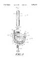
- FIG. 1is an unassembled perspective view of a modular knee prosthesis according to the present invention that includes a right knee femoral component, but that is generally designed for use in both right and left knees.
- FIG. 2Ais a perspective view of one embodiment of a femoral component for use with the right knee and for use with the modular knee prosthesis of FIG. 1.
- FIG. 2Bis a perspective view of another embodiment of a femoral component useful with the modular prosthesis of FIG. 1, and that is designed for use in both right and left knees.
- FIG. 3is a bottom view of the femoral component of FIG. 1.
- FIG. 4Ais a side view of one embodiment of a securing bolt useful with the modular knee prosthesis of FIG. 1.
- FIG. 4Bis a top view of the securing bolt of FIG. 4A.
- FIG. 5Ais a side view of an alternate embodiment of a securing bolt useful with the modular knee prosthesis of FIG. 1.
- FIG. 5Bis a top view, from the shaft, of the securing bolt of FIG. 5A.
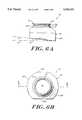
- FIG. 6Ais a side view of a collar useful with the modular knee prosthesis of FIG. 1.
- FIG. 6Bis a top view of the collar of FIG. 6A.
- FIG. 6Cis a cross-sectional view of the collar of FIG. 6A taken along line B--B of FIG. 6B.
- FIG. 7is a cross-sectional view of the femoral stem of FIG. 1 along line
- the modular knee prosthesis 10 of the inventionincludes a femoral stem 14, a collar 26, a femoral component 40, and a securing bolt 56.
- the knee prosthesis 10can further include a snap-ring 12, similar in type and operation to that described in U.S. Pat. No. 5,152,796, which is herein incorporated by reference.
- the illustrated modular knee prosthesis 10, except the illustrated femoral component,is suitable for use, without modification, as either a left or a right knee prosthesis.
- the femoral component 40has a pair of condylar portions 42A, 42B that are connected by an intercondylar region or boss 44.
- the femoral component 40has a superior articulation surface 45 and an opposed inferior surface 46.
- the femoral component 40has a posterior side 36 and an anterior side 38.
- the anterior side 38 of the femoral component 40includes a patellar groove 54, shown in FIG. 3, within which seats a patellar prosthetic component (not shown).
- the superior surfaces 45 of the curved condylar portions 42A, 42Barticulate with a prosthetic tibial component (not shown) mounted on the head of the tibia, in a manner well known to those of ordinary skill in the art.
- the boss structure 44has a pair of substantially vertical side walls 44A that are generally orthogonal to a top, inferior surface 44B.
- the top surface 44Bpreferably has formed thereon a pair of raised ridges 44C that constitute a collar anti-rotation element, as described in further detail below.
- the boss 44further has a cavity 70 formed within a bottom superior surface 44D.
- An aperture 78 disposed within the cavity 70extends between the superior and inferior surfaces 45, 46, respectively, of the boss structure 44 and has a selected shape such that it can be elongated either in the anterior-posterior direction or the medial-lateral direction.
- aperture 78is elongated in the anterior-posterior direction.
- the shape of the aperturecan be elliptical, oval, spherical, or of any other suitable shape that allows a sufficient amount of translation of the securing bolt shaft when the bolt is mounted within the aperture.
- the transverse planeis defined as the horizontal plane that extends through the knee of an upright subject and that is orthogonal to both the coronal plane and the sagittal plane, as will be appreciated by those having ordinary skill in the art.
- the cavity 70preferably has a pair of arcuate medial and lateral side walls 72, and a pair of substantially flat anterior and posterior side walls 74 that form a bolt anti-rotation mechanism, as described in further detail below.
- the cavityfurther includes an endwall 76 that has a substantially spherical or rounded shape for seating a correspondingly shaped head of the securing bolt 56.
- the inferior surface 46 of the condylar portions 42A, 42Bforms a series of integral surfaces that extend between the anterior and posterior sides of the femoral component.
- the inferior surface of each condylar portion 42comprises an anterior vertical surface 80, an axially spaced and downwardly extending canted surface 82, a substantially horizontal surface 84, an axially spaced and upwardly extending canted surface 86, and a posterior vertical surface 88.
- the horizontal surface 84 of each condylar portionhas an indentation 90 that extends partly into the inferior surface of each condylar portion. The indentation allows the surgeon to grasp and handle the femoral component via a suitable handling instrument.
- the femoral component 40 and boss 44can have a variety of shapes, as shown in FIGS. 2A and 2B. Elements of the femoral component 40' which are common to the elements of the femoral component of FIGS. 1 and 3 are designated with like reference numerals with a superscript prime for FIG. 2A components, and with a superscript double prime for FIG. 2B components.
- the femoral component 40' of FIG. 2Ahas a boss structure 44' that has a second selected shape. Additionally, the illustrated raised ridges 44C' forming the collar anti-rotation mechanism are axially offset relative to each other. With reference to FIG. 2B, the boss structure 44" of the illustrated femoral component 40" has a third preferred shape. The raised ridges 44C" of the boss structure are also axially offset, similar to those of FIG. 2A. Those of ordinary skill will readily recognize that other shapes of the femoral component 40, boss structure 44 and condylar portions 42 exist.
- FIGS. 4A-5Billustrate preferred embodiments of the securing bolt of FIG. 1.
- the bolt 56 of the first embodimenthas a shaft portion 58 that extends upwardly and outwardly from a bolt head 60.
- the shafthas a lower unthreaded portion 58A that has an outer diameter (D1) less than the outer diameter of bolt head 60, and an upper, threaded portion 58C that is integral with the lower unthreaded portion 58A.
- an indented neck portion 58Bseparates the upper and lower portions 58C, 58A of bolt 56.
- the outer diameter (D2) of the upper portion 58Cis preferably slightly less than the outer diameter (D1) of the lower shaft portion 58A.
- the bolt head portion 60has a boss aperture-engaging surface 62, and an opposed, top surface 64 that includes a pair of canted surfaces 64A that join at an apex 64B.
- the aperture-engaging surface 62preferably has a rounded or spherical shape complementary to that of the endwall 76 of the boss cavity 70.
- the mating engagement of the aperture-engaging surface 62 of the bolt head 60 and the shaped endwall 76 of the boss cavity 70preferably positions the bolt shaft within the aperture.
- the bolt shaft 58extends from the boss top surface 44B at a selected angle determined by the shape of the aperture 78 and by the mounting angle of the collar 26.
- the shape of the aperture 78helps determine the allowable angle range of the bolt shaft by allowing the bolt shaft to translate within the confines of the aperture, and to eventually seat at a selected position therein, as described in further detail below.
- endwall 76 and aperture-engaging surface 62are shown with spherically-shaped contours, those of ordinary skill will recognize that other compatible configurations are possible.
- the top surface 64 of the bolt head 60has a peripheral surface 66 that is defined by a pair of opposed, arcuate sides 66A and a pair of opposed, substantially flat sides 66B.
- the flat sides 66Bmatingly engage the flat side walls 74 of the boss cavity 70 and cooperate therewith to secure the bolt within the cavity and to prevent unwanted rotation of the bolt when secured therein.
- the boltis constructed such that the shaft portion 58 of the bolt extends from a generally centrally located position on the bolt head 60. This arrangement allows the bolt shaft to extend from the inferior surface of the femoral component when the bolt is mounted within the boss aperture at a selected location and desired angle relative to the inferior surface 46.
- FIGS. 5A and 5Billustrate another embodiment of a securing bolt 56 constructed according to the invention.
- bolt 56is similar to that described above and shown in FIGS. 4A and 4B, except that the shaft 58 is positioned on the bolt head 60 in an offset, non-centered position.
- the shaft portion 58 of the boltextends upwardly from a position axially offset a selected distance from a generally centrally located position of the bolt head 60.
- the distance by which the shaft is offset from this generally centrally located positionis in the range of about 0 mm to about 5 mm.
- the offset distanceis about 2 mm.
- This offset construction of the bolt 56allows the bolt shaft 58 to extend from the boss inferior surface 46, when the bolt is mounted within the boss aperture, at a selected angle and axial orientation relative to the inferior surface 46 of the femoral component 40.
- an offset bolt(FIGS. 5A and 5B) oriented in either an anterior or posterior direction may be necessary for differing anatomies, or where bony deficiencies exist in certain areas of the femur.
- the illustrated bolt of FIGS. 4A and 4Bcan be used in both left or right side prostheses where no bolt offset is desired, for example, for differing anatomies or where bony deficiencies exist in certain areas of the femur.
- the offset bolt illustrated in FIGS. 5A and 5Bcan be used in both right and left side prostheses where an anterior or posterior, or medial or lateral offset is needed.
- the collar 26has a central body portion 28 that has an outer peripheral surface 29 and a boss engaging surface 30.
- the collarfurther includes a neck portion 32 that extends upwardly from a stem-seating surface 31.
- the neck 32preferably includes a first annular portion 32A and a stepped annular portion 32B.
- a lip 32C formed along the top of the second stepped annular surface 32Boverhangs the first stepped surface 32A.
- the distal end of the stem 14, when assembled with the collar,preferably engages the stem-seating surface 31, which is sized to receive femoral stems having various diameters, including diameters of about 13 mm and about 15 mm.
- the boss engaging surface 30is preferably canted and forms an angle with the transverse plane 22.
- the angle ( ⁇ )is preferably between about 0° and about 15°.
- the boss engaging surface 30can be canted in the anterior-posterior direction to either the anterior or posterior side as measured in the sagittal plane.
- the surface 30can be canted in the medial-lateral direction to either the medial side or the posterior side as measured in the coronal plane.
- the angle ( ⁇ )can range between about 0° and about 15° in any direction.
- This varied collar angulationprovides a plurality of stem mounting angles which is compatible with the various possible orientations of the femoral stem when mounted within the distal portion of the femur.
- the boss mounting surface 30can be configured to provide any combination of coronal and sagittal plane angulations that are constrained by the foregoing angle ranges.
- the collar 26can be used with either right or left side knee prostheses. Generally, the collar is positioned such that the angle ( ⁇ ) is to the lateral side of the prosthesis, as measured in the coronal plane. The same collar can be used in either a left or right side prosthesis by simply reversing the orientation of the collar on the prosthesis to ensure a lateral angle for the femoral stem 14.
- the collar peripheral surface 29has a pair of opposed arcuate sides 29B and a pair of opposed, flat sides 29A.
- Flat sides 29Aare adapted to engage the raised ridges 44C of the boss top surface 44B. The mating contact between the raised ridges 44C and the flat sides 29A of the collar peripheral surface prevents unwanted rotation of the collar when mounted on the boss top surface 44B.
- the collar 26further has a central aperture 34 which seats the bolt shaft 58.
- the aperture 34has a funnel-like portion 34A adjacent the boss mounting surface 30, and a cylindrical portion 34B that extends upwardly from the funnel-like portion 34A to the neck 32 of the collar.
- the funnel-like portion 34Aprovides an additional clearance space for bolt insertion.
- the femoral stem 14has an elongate body 15 that extends along a longitudinal axis (x).
- a series of spaced flutes 16are formed along a proximal portion 15A of the body 15, FIG. 1.
- the flutes 16inhibit rotation of the stem within the medullary canal of the femur.
- the bottom portion 15B, e.g., distal end, of the stem body 15further has a collar and bolt-receiving aperture 16 formed therein.
- the aperture 16 formed in the stem bottom surface 15Chas a first aperture portion 16A having an outer diameter (D3) that is slightly larger that the outer diameter of the first annular surface 32A of the collar, FIG. 5A, thereby allowing the collar neck to mount within the stem aperture 16.
- the aperture 16has a second axially spaced portion 16B that has a diameter (D4) that is smaller than diameter (D3) but slightly larger than the diameter (D1) of the bolt shaft 58, FIG. 6A.
- the aperturefurther includes an axially spaced, threaded third portion 16C having an outer diameter (D5) that is less than the diameter (D1), but larger than the diameter (D2) of the bolt shaft.
- This axial successive configuration of the aperture 16receives the axially spaced portions of the bolt shaft 58A-58C, and allows the bolt threaded portion 58C to threadingly engage with the threaded aperture portion 16C.
- the outer diameter of the stem bottom portionpreferably ranges between about 10 mm and about 20 mm, and most preferably between about 10.5 mm and about 15 mm.
- the illustrated stem 14is suitable for use, without modification, in both left and right side prostheses.
- the collar 26When assembled, the collar 26 is mounted on the top surface 46, e.g., inferior surface, of the boss 44, and the flat sides 66B of the collar are aligned with the raised ridges 44C. The raised ridges prevent unwanted rotation of the collar when mounted thereon.
- the distal end of the femoral stemis then placed over the neck 32 of the collar 26.
- the neck portion 32seats within the first portion 16A of the stem aperture 16, but is not rigidly captured therein.
- the stemis rotatable about the stem axis (x) independent of the collar, since the raised ridges of the boss prevent the collar from rotating.
- the securing bolt 56is then inserted into the boss cavity 70 from the underside of the boss and through the boss aperture 78, such that the bolt shaft extends upwardly from the boss top surface.
- the spherical engaging surface 62 of the bolt head 60mates with and engages the similarly configured endwall 76 of the cavity.
- the selected shape of the cavity endwallallows the bolt shaft to seat within the cavity at an angle that is determined by the collar 26.
- the boss mounting surface 30 of the collar 26determines the stem angulation and the position at which the bolt shaft protrudes into and extends from the collar 26.
- the threaded portion 58C of the bolt shaft 58threadedly engages the threaded portion 16C of the stem aperture and fixedly secures the stem and collar to the femoral component.
- the collaris pressure fitted between the stem and boss by the threaded engagement of the bolt and stem.
- a significant feature of the present inventionis the complementary shape of the cavity endwall and the mounting surface of the bolt head, which cooperate to position the bolt at a selected angle determined by the collar mounting angle.
- the varied positions in which the bolt shaft can be positionedis further facilitated by the selected shape of the aperture, which is preferably elongated in the anterior-posterior direction.
- the aperturecan be elongated in any selected direction in the transverse plane, for example, the medial-lateral direction.
- the bolt shaft of the securing boltcan be centrally located or offset, depending upon the surgeon's needs.
- the stem and collarcan be separately provided in a packaged modular knee prosthesis.
- the packaged modular knee prosthesiscan include a femoral component, an offset and/or a non offset type bolt, a collar or collars having a 5 degree and/or a 7 degree canted mounting surface, and a femoral stem.
- the modular knee prosthesis 10 of the inventioncan further include a snap-ring 12, FIG. 1, to provide a redundant mechanism for securing the collar to the femoral stem.
- the illustrated snap-ring 12preferably mounts in a circumferential slot formed by the second annular surface 32B of the collar, FIG. 6A, and a corresponding groove formed along the bottom portion of the stem aperture (not shown). The snap-ring seats partially within the circumferential slot within the collar and within the groove formed in the stem, thereby locking the stem onto the collar.
Landscapes
- Health & Medical Sciences (AREA)
- Orthopedic Medicine & Surgery (AREA)
- Physical Education & Sports Medicine (AREA)
- Cardiology (AREA)
- Oral & Maxillofacial Surgery (AREA)
- Transplantation (AREA)
- Engineering & Computer Science (AREA)
- Biomedical Technology (AREA)
- Heart & Thoracic Surgery (AREA)
- Vascular Medicine (AREA)
- Life Sciences & Earth Sciences (AREA)
- Animal Behavior & Ethology (AREA)
- General Health & Medical Sciences (AREA)
- Public Health (AREA)
- Veterinary Medicine (AREA)
- Prostheses (AREA)
Abstract
Description
Claims (22)
Priority Applications (12)
| Application Number | Priority Date | Filing Date | Title |
|---|---|---|---|
| US08/347,828US5556433A (en) | 1994-12-01 | 1994-12-01 | Modular knee prosthesis |
| AU39029/95AAU699390B2 (en) | 1994-12-01 | 1995-11-23 | Modular knee prosthesis |
| JP32943095AJP3739122B2 (en) | 1994-12-01 | 1995-11-27 | Modular knee prosthesis |
| CA002164042ACA2164042C (en) | 1994-12-01 | 1995-11-29 | Modular knee prosthesis |
| DE69516639TDE69516639T2 (en) | 1994-12-01 | 1995-11-30 | Modular knee prosthesis |
| AT95308642TATE192316T1 (en) | 1994-12-01 | 1995-11-30 | MODULAR KNEE PROSTHESIS |
| SI9530396TSI0714645T1 (en) | 1994-12-01 | 1995-11-30 | Modular knee prosthesis |
| DK95308642TDK0714645T3 (en) | 1994-12-01 | 1995-11-30 | Modular knee prosthesis |
| PT95308642TPT714645E (en) | 1994-12-01 | 1995-11-30 | MODULAR KNEES PROTESE |
| EP95308642AEP0714645B1 (en) | 1994-12-01 | 1995-11-30 | Modular knee prosthesis |
| ES95308642TES2145225T3 (en) | 1994-12-01 | 1995-11-30 | MODULAR KNEE PROSTHESIS. |
| GR20000401751TGR3034059T3 (en) | 1994-12-01 | 2000-07-28 | Modular knee prosthesis |
Applications Claiming Priority (1)
| Application Number | Priority Date | Filing Date | Title |
|---|---|---|---|
| US08/347,828US5556433A (en) | 1994-12-01 | 1994-12-01 | Modular knee prosthesis |
Publications (1)
| Publication Number | Publication Date |
|---|---|
| US5556433Atrue US5556433A (en) | 1996-09-17 |
Family
ID=23365452
Family Applications (1)
| Application Number | Title | Priority Date | Filing Date |
|---|---|---|---|
| US08/347,828Expired - LifetimeUS5556433A (en) | 1994-12-01 | 1994-12-01 | Modular knee prosthesis |
Country Status (12)
| Country | Link |
|---|---|
| US (1) | US5556433A (en) |
| EP (1) | EP0714645B1 (en) |
| JP (1) | JP3739122B2 (en) |
| AT (1) | ATE192316T1 (en) |
| AU (1) | AU699390B2 (en) |
| CA (1) | CA2164042C (en) |
| DE (1) | DE69516639T2 (en) |
| DK (1) | DK0714645T3 (en) |
| ES (1) | ES2145225T3 (en) |
| GR (1) | GR3034059T3 (en) |
| PT (1) | PT714645E (en) |
| SI (1) | SI0714645T1 (en) |
Cited By (93)
| Publication number | Priority date | Publication date | Assignee | Title |
|---|---|---|---|---|
| US5683472A (en)* | 1995-12-29 | 1997-11-04 | Johnson & Johnson Professional, Inc. | Femoral stem attachment for a modular knee prosthesis |
| US5755800A (en)* | 1996-12-23 | 1998-05-26 | Johnson & Johnson Professional, Inc. | Modular joint prosthesis augmentation system |
| US5766255A (en)* | 1996-12-23 | 1998-06-16 | Johnson & Johnson Professional, Inc. | Modular joint prosthesis stabilization and augmentation system |
| US5879391A (en)* | 1996-09-30 | 1999-03-09 | Johnson & Johnson Professional, Inc. | Modular prosthesis |
| US6063122A (en)* | 1998-06-22 | 2000-05-16 | Johnson & Johnson Professional, Inc. | Jack screw adapter for joint prosthesis |
| US6071311A (en)* | 1998-08-14 | 2000-06-06 | Johnson & Johnson Professional, Inc. | Cylindrical box femoral stem |
| WO2000038598A1 (en)* | 1998-12-30 | 2000-07-06 | Biomet, Inc. | Method and apparatus for enabling access to an intramedullary canal of a femur through a femoral knee joint prosthesis |
| WO2000051528A1 (en)* | 1999-03-01 | 2000-09-08 | Biomet, Inc. | Method and apparatus for enabling access to an intramedullary canal of a femur through a femoral knee joint prosthesis |
| US6126693A (en)* | 1998-09-18 | 2000-10-03 | Depuy Orthopaedics, Inc. | Tapped box femoral stem attachment for a modular knee prosthesis |
| US6162255A (en)* | 1998-10-15 | 2000-12-19 | Depuy Orthopaedics, Inc. | Stem offset mechanism for joint prosthesis |
| US6171342B1 (en)* | 1996-07-23 | 2001-01-09 | Depuy Orthopaedics, Inc. | Medical fastening system |
| US6416552B1 (en) | 1998-12-30 | 2002-07-09 | Biomet, Inc. | Method and apparatus for enabling access to an intramedullary canal of a femur through a femoral knee joint prosthesis |
| US6527807B1 (en)* | 1998-09-09 | 2003-03-04 | Johnson & Johnson Professional, Inc. | Femoral stem attachment for a modular knee prosthesis |
| US20030158606A1 (en)* | 2002-02-20 | 2003-08-21 | Coon Thomas M. | Knee arthroplasty prosthesis and method |
| WO2003068119A2 (en) | 2002-02-14 | 2003-08-21 | Abendschein Walter F | Method and instrumentation for patello-femoral joint replacement |
| US6616696B1 (en) | 1998-09-04 | 2003-09-09 | Alan C. Merchant | Modular knee replacement system |
| US20030220697A1 (en)* | 2002-05-24 | 2003-11-27 | Justin Daniel F. | Modular femoral components for knee arthroplasty |
| US20030225457A1 (en)* | 2002-05-24 | 2003-12-04 | Justin Daniel F. | Femoral components for knee arthroplasty |
| US6673114B2 (en) | 2000-05-03 | 2004-01-06 | Smith & Nephew, Inc. | Multi modular trialing system and instrumentation |
| US20040083003A1 (en)* | 2002-10-23 | 2004-04-29 | Wasielewski Ray C. | Biologic modular tibial and femoral component augments for use with total knee arthroplasty |
| US20040122521A1 (en)* | 2002-12-20 | 2004-06-24 | Lee Chelynne Nicole | Prosthetic knee implant with modular augment |
| US6783551B1 (en) | 1998-12-30 | 2004-08-31 | Biomet, Inc. | Method and apparatus for enabling access to an intramedullary canal of a femur through a femoral knee joint prosthesis |
| US20050033437A1 (en)* | 2002-05-23 | 2005-02-10 | Pioneer Laboratories, Inc. | Artificial disc device |
| US20050076602A1 (en)* | 2003-09-17 | 2005-04-14 | Raymond Routhier | Asymmetric drive pin |
| US20050154471A1 (en)* | 2004-01-12 | 2005-07-14 | Luke Aram | Systems and methods for compartmental replacement in a knee |
| US20050177242A1 (en)* | 2004-01-12 | 2005-08-11 | Lotke Paul A. | Patello-femoral prosthesis |
| US20050203629A1 (en)* | 2004-02-26 | 2005-09-15 | George Cipolletti | Modular knee prosthesis |
| US6953479B2 (en) | 2001-07-16 | 2005-10-11 | Smith & Nephew, Inc. | Orthopedic implant extension |
| US20050256581A1 (en)* | 2002-05-23 | 2005-11-17 | Pioneer Laboratories, Inc. | Artificial disc device |
| US20050278034A1 (en)* | 2002-11-22 | 2005-12-15 | Johnson Erin M | Modular knee prosthesis |
| EP1623686A2 (en) | 2004-08-05 | 2006-02-08 | DePuy Products, Inc. | Modular orthopaedic implant system |
| US20060058884A1 (en)* | 2004-01-12 | 2006-03-16 | Luke Aram | Systems and methods for compartmental replacement in a knee |
| US20060173547A1 (en)* | 2003-12-08 | 2006-08-03 | Ensign Michael D | Modular femoral knee stem extender |
| US20060195195A1 (en)* | 2003-07-17 | 2006-08-31 | Albert Burstein | Mobile bearing knee prosthesis |
| US20060265079A1 (en)* | 2005-05-19 | 2006-11-23 | Howmedica Osteonics Corp. | Modular keel tibial component |
| US20070203582A1 (en)* | 2006-02-28 | 2007-08-30 | Howmedica Osteonics Corp. | Modular tibial implant |
| US20080109081A1 (en)* | 2003-10-22 | 2008-05-08 | Qi-Bin Bao | Joint Arthroplasty Devices Having Articulating Members |
| US7422605B2 (en) | 2003-07-17 | 2008-09-09 | Exactech, Inc. | Mobile bearing knee prosthesis |
| US7445639B2 (en) | 2001-02-23 | 2008-11-04 | Biomet Manufacturing Corp. | Knee joint prosthesis |
| US7497874B1 (en) | 2001-02-23 | 2009-03-03 | Biomet Manufacturing Corp. | Knee joint prosthesis |
| US20090088862A1 (en)* | 2007-09-27 | 2009-04-02 | Kyle Thomas | Stem extension and adaptor for use with a knee orthopaedic implant |
| US7544211B2 (en) | 2006-02-01 | 2009-06-09 | Tornier | Offset stem tibial implant |
| US20090306787A1 (en)* | 2006-04-04 | 2009-12-10 | Paul Charles Crabtree | Trial coupler systems and methods |
| US7695519B2 (en) | 2005-07-08 | 2010-04-13 | Howmedica Osteonics Corp. | Modular tibial baseplate |
| US7799084B2 (en) | 2002-10-23 | 2010-09-21 | Mako Surgical Corp. | Modular femoral component for a total knee joint replacement for minimally invasive implantation |
| US7842093B2 (en) | 2006-07-18 | 2010-11-30 | Biomet Manufacturing Corp. | Method and apparatus for a knee implant |
| US7846162B2 (en) | 2005-05-18 | 2010-12-07 | Sonoma Orthopedic Products, Inc. | Minimally invasive actuable bone fixation devices |
| US7909825B2 (en) | 2006-11-22 | 2011-03-22 | Sonoma Orthepedic Products, Inc. | Fracture fixation device, tools and methods |
| US20110071642A1 (en)* | 2008-03-07 | 2011-03-24 | Aesculap Ag | Medical implant and knee joint endoprosthesis |
| US7998217B1 (en) | 2005-02-02 | 2011-08-16 | Biomet Manufacturing Corp. | Modular offset stem implants |
| US8002840B2 (en) | 2004-01-12 | 2011-08-23 | Depuy Products, Inc. | Systems and methods for compartmental replacement in a knee |
| US8110005B2 (en) | 2000-04-10 | 2012-02-07 | Biomet Manufacturing Corp. | Modular prosthesis and use thereof for replacing a radial head |
| US8157869B2 (en) | 2007-01-10 | 2012-04-17 | Biomet Manufacturing Corp. | Knee joint prosthesis system and method for implantation |
| US8163028B2 (en) | 2007-01-10 | 2012-04-24 | Biomet Manufacturing Corp. | Knee joint prosthesis system and method for implantation |
| US8187280B2 (en) | 2007-10-10 | 2012-05-29 | Biomet Manufacturing Corp. | Knee joint prosthesis system and method for implantation |
| US8287539B2 (en) | 2005-05-18 | 2012-10-16 | Sonoma Orthopedic Products, Inc. | Fracture fixation device, tools and methods |
| US8328873B2 (en) | 2007-01-10 | 2012-12-11 | Biomet Manufacturing Corp. | Knee joint prosthesis system and method for implantation |
| US8535382B2 (en) | 2000-04-10 | 2013-09-17 | Biomet Manufacturing, Llc | Modular radial head prostheses |
| US8540775B2 (en) | 2007-06-11 | 2013-09-24 | Aesculap Ag | Modular implant part and knee joint prosthesis |
| US8562616B2 (en) | 2007-10-10 | 2013-10-22 | Biomet Manufacturing, Llc | Knee joint prosthesis system and method for implantation |
| US8568486B2 (en) | 2010-07-24 | 2013-10-29 | Zimmer, Inc. | Asymmetric tibial components for a knee prosthesis |
| US8591594B2 (en) | 2010-09-10 | 2013-11-26 | Zimmer, Inc. | Motion facilitating tibial components for a knee prosthesis |
| US8628580B2 (en) | 2010-07-24 | 2014-01-14 | Zimmer, Inc. | Tibial prosthesis |
| US8758444B2 (en) | 2011-11-21 | 2014-06-24 | Zimmer, Inc. | Tibial baseplate with asymmetric placement of fixation structures |
| US8852195B2 (en) | 2004-07-09 | 2014-10-07 | Zimmer, Inc. | Guide templates for surgical implants and related methods |
| US8920509B2 (en) | 2000-04-10 | 2014-12-30 | Biomet Manufacturing, Llc | Modular radial head prosthesis |
| US8961516B2 (en) | 2005-05-18 | 2015-02-24 | Sonoma Orthopedic Products, Inc. | Straight intramedullary fracture fixation devices and methods |
| US8961612B2 (en) | 2012-08-30 | 2015-02-24 | Biomet Manufacturing, Llc | Knee component having orbital interface boss |
| US8998996B2 (en) | 2012-09-20 | 2015-04-07 | Depuy (Ireland) | Knee prosthesis system with standard and distal offset joint line |
| US9060820B2 (en) | 2005-05-18 | 2015-06-23 | Sonoma Orthopedic Products, Inc. | Segmented intramedullary fracture fixation devices and methods |
| US9155574B2 (en) | 2006-05-17 | 2015-10-13 | Sonoma Orthopedic Products, Inc. | Bone fixation device, tools and methods |
| US9233011B2 (en) | 2006-09-15 | 2016-01-12 | Pioneer Surgical Technology, Inc. | Systems and apparatuses for inserting an implant in intervertebral space |
| US9241807B2 (en) | 2011-12-23 | 2016-01-26 | Pioneer Surgical Technology, Inc. | Systems and methods for inserting a spinal device |
| US9320603B2 (en) | 2012-09-20 | 2016-04-26 | Depuy (Ireland) | Surgical instrument system with multiple lengths of broaches sharing a common geometry |
| US9381090B2 (en) | 2010-07-24 | 2016-07-05 | Zimmer, Inc. | Asymmetric tibial components for a knee prosthesis |
| US9532879B2 (en) | 2012-09-20 | 2017-01-03 | Depuy Ireland Unlimited Company | Femoral knee prosthesis system with augments and multiple lengths of sleeves sharing a common geometry |
| US20170027707A1 (en)* | 2013-12-20 | 2017-02-02 | Adler Ortho S.R.L. | Femoral component for knee prostheses |
| US9770278B2 (en) | 2014-01-17 | 2017-09-26 | Arthrex, Inc. | Dual tip guide wire |
| US9814499B2 (en) | 2014-09-30 | 2017-11-14 | Arthrex, Inc. | Intramedullary fracture fixation devices and methods |
| US9907655B2 (en) | 2016-06-17 | 2018-03-06 | Arthrex, Inc. | Components for artificial joints |
| CN109227594A (en)* | 2018-09-19 | 2019-01-18 | 广东工业大学 | A kind of snap ring-type robot connection component |
| US10182917B2 (en) | 2016-04-11 | 2019-01-22 | Arthrex, Inc. | Components for artificial joints |
| US10188530B2 (en) | 2010-12-17 | 2019-01-29 | Zimmer, Inc. | Provisional tibial prosthesis system |
| US10278827B2 (en) | 2015-09-21 | 2019-05-07 | Zimmer, Inc. | Prosthesis system including tibial bearing component |
| US10307198B2 (en) | 2013-03-15 | 2019-06-04 | Depuy Ireland Unlimited Company | Instruments and method for use in disassembling implants |
| US10675153B2 (en) | 2017-03-10 | 2020-06-09 | Zimmer, Inc. | Tibial prosthesis with tibial bearing component securing feature |
| US10835380B2 (en) | 2018-04-30 | 2020-11-17 | Zimmer, Inc. | Posterior stabilized prosthesis system |
| USD907771S1 (en) | 2017-10-09 | 2021-01-12 | Pioneer Surgical Technology, Inc. | Intervertebral implant |
| US10898337B2 (en) | 2011-11-18 | 2021-01-26 | Zimmer, Inc. | Tibial bearing component for a knee prosthesis with improved articular characteristics |
| US11147682B2 (en) | 2017-09-08 | 2021-10-19 | Pioneer Surgical Technology, Inc. | Intervertebral implants, instruments, and methods |
| US11324598B2 (en) | 2013-08-30 | 2022-05-10 | Zimmer, Inc. | Method for optimizing implant designs |
| US11324599B2 (en) | 2017-05-12 | 2022-05-10 | Zimmer, Inc. | Femoral prostheses with upsizing and downsizing capabilities |
| US11426282B2 (en) | 2017-11-16 | 2022-08-30 | Zimmer, Inc. | Implants for adding joint inclination to a knee arthroplasty |
Families Citing this family (21)
| Publication number | Priority date | Publication date | Assignee | Title |
|---|---|---|---|---|
| US5782921A (en)* | 1996-07-23 | 1998-07-21 | Johnson & Johnson Professional, Inc. | Modular knee prosthesis |
| US5782920A (en)* | 1996-11-14 | 1998-07-21 | Johnson & Johnson Professional, Inc. | Offset coupling for joint prosthesis |
| US6146424A (en)* | 1998-07-30 | 2000-11-14 | Sulzer Orthopedics Inc. | Offset press-fit tibial stem |
| US6120509A (en)* | 1998-09-01 | 2000-09-19 | Sulzer Orthopedics Inc. | Intramedullary reference datum instrument |
| US6478799B1 (en)* | 2000-06-29 | 2002-11-12 | Richard V. Williamson | Instruments and methods for use in performing knee surgery |
| US6482209B1 (en) | 2001-06-14 | 2002-11-19 | Gerard A. Engh | Apparatus and method for sculpting the surface of a joint |
| US7182786B2 (en) | 2002-04-25 | 2007-02-27 | Zimmer Technology, Inc. | Modular bone implant, tool, and method |
| US6875239B2 (en) | 2002-04-25 | 2005-04-05 | Medicinelodge, Inc. | Modular prosthesis for replacing bone and method |
| US6902583B2 (en) | 2002-04-25 | 2005-06-07 | Medicinelodge, Inc. | Tripartite attachment mechanism and method for a modular prosthesis |
| US7771483B2 (en) | 2003-12-30 | 2010-08-10 | Zimmer, Inc. | Tibial condylar hemiplasty implants, anchor assemblies, and related methods |
| US7922772B2 (en) | 2002-05-24 | 2011-04-12 | Zimmer, Inc. | Implants and related methods and apparatus for securing an implant on an articulating surface of an orthopedic joint |
| US6866683B2 (en) | 2002-12-13 | 2005-03-15 | Medicine Lodge, Inc. | Modular implant for joint reconstruction and method of use |
| US6887276B2 (en) | 2002-12-13 | 2005-05-03 | Medicine Lodge, Inc | Modular implant for joint reconstruction and method of use |
| US7867236B2 (en) | 2003-12-30 | 2011-01-11 | Zimmer, Inc. | Instruments and methods for preparing a joint articulation surface for an implant |
| US8579985B2 (en) | 2006-12-07 | 2013-11-12 | Ihip Surgical, Llc | Method and apparatus for hip replacement |
| US8974540B2 (en) | 2006-12-07 | 2015-03-10 | Ihip Surgical, Llc | Method and apparatus for attachment in a modular hip replacement or fracture fixation device |
| EP2094197B8 (en) | 2006-12-07 | 2016-03-09 | IHip Surgical, LLC | Apparatus for total hip replacement |
| US9004871B2 (en) | 2012-08-17 | 2015-04-14 | General Electric Company | Stacked wheel assembly for a turbine system and method of assembling |
| US9279325B2 (en) | 2012-11-08 | 2016-03-08 | General Electric Company | Turbomachine wheel assembly having slotted flanges |
| US9138321B2 (en)* | 2013-03-15 | 2015-09-22 | Depuy (Ireland) | Prosthetic components with secondary retention |
| EP3222234B1 (en)* | 2015-10-28 | 2020-10-21 | Zhao, Dewei | Porous tantalum metal hollow screw |
Citations (12)
| Publication number | Priority date | Publication date | Assignee | Title |
|---|---|---|---|---|
| DE473375C (en)* | 1929-03-14 | Albert Schnellpressen | Screw for tightening and adjusting two machine parts with an eccentric head | |
| US4822366A (en)* | 1986-10-16 | 1989-04-18 | Boehringer Mannheim Corporation | Modular knee prosthesis |
| US4904110A (en)* | 1988-06-17 | 1990-02-27 | Unarco Industries, Inc. | Fastening arrangement for shelving system or the like |
| US4985037A (en)* | 1989-05-22 | 1991-01-15 | Petersen Thomas D | Universal modular prosthesis stem extension |
| US5127914A (en)* | 1989-02-10 | 1992-07-07 | Calderale Pasquale M | Osteosynthesis means for the connection of bone fracture segments |
| US5133760A (en)* | 1990-02-12 | 1992-07-28 | Alvarado Orthopedic Research, Inc. | Universal modular prosthesis stem extension |
| US5152796A (en)* | 1988-12-27 | 1992-10-06 | Johnson & Johnson Orthopaedics, Inc. | Modular knee prosthesis |
| EP0531263A1 (en)* | 1991-08-08 | 1993-03-10 | Gemed Ltd | Knee prosthesis provided with articulations between femoral and tibial components and their respective stems |
| US5290313A (en)* | 1992-11-23 | 1994-03-01 | Zimmer, Inc. | Offset prosthetic stem extension |
| US5326359A (en)* | 1991-11-29 | 1994-07-05 | Etablissements Tornier | Knee prosthesis with adjustable centro-medullary stem |
| US5336225A (en)* | 1991-05-24 | 1994-08-09 | Orthopaedic Biosystems, Ltd. | Bone fastening device |
| EP0529408B1 (en)* | 1991-08-24 | 1995-12-20 | Aesculap Ag | Knee endoprosthesis |
- 1994
- 1994-12-01USUS08/347,828patent/US5556433A/ennot_activeExpired - Lifetime
- 1995
- 1995-11-23AUAU39029/95Apatent/AU699390B2/ennot_activeExpired
- 1995-11-27JPJP32943095Apatent/JP3739122B2/ennot_activeExpired - Lifetime
- 1995-11-29CACA002164042Apatent/CA2164042C/ennot_activeExpired - Fee Related
- 1995-11-30DEDE69516639Tpatent/DE69516639T2/ennot_activeExpired - Lifetime
- 1995-11-30PTPT95308642Tpatent/PT714645E/enunknown
- 1995-11-30DKDK95308642Tpatent/DK0714645T3/enactive
- 1995-11-30EPEP95308642Apatent/EP0714645B1/ennot_activeExpired - Lifetime
- 1995-11-30SISI9530396Tpatent/SI0714645T1/enunknown
- 1995-11-30ESES95308642Tpatent/ES2145225T3/ennot_activeExpired - Lifetime
- 1995-11-30ATAT95308642Tpatent/ATE192316T1/enactive
- 2000
- 2000-07-28GRGR20000401751Tpatent/GR3034059T3/enunknown
Patent Citations (12)
| Publication number | Priority date | Publication date | Assignee | Title |
|---|---|---|---|---|
| DE473375C (en)* | 1929-03-14 | Albert Schnellpressen | Screw for tightening and adjusting two machine parts with an eccentric head | |
| US4822366A (en)* | 1986-10-16 | 1989-04-18 | Boehringer Mannheim Corporation | Modular knee prosthesis |
| US4904110A (en)* | 1988-06-17 | 1990-02-27 | Unarco Industries, Inc. | Fastening arrangement for shelving system or the like |
| US5152796A (en)* | 1988-12-27 | 1992-10-06 | Johnson & Johnson Orthopaedics, Inc. | Modular knee prosthesis |
| US5127914A (en)* | 1989-02-10 | 1992-07-07 | Calderale Pasquale M | Osteosynthesis means for the connection of bone fracture segments |
| US4985037A (en)* | 1989-05-22 | 1991-01-15 | Petersen Thomas D | Universal modular prosthesis stem extension |
| US5133760A (en)* | 1990-02-12 | 1992-07-28 | Alvarado Orthopedic Research, Inc. | Universal modular prosthesis stem extension |
| US5336225A (en)* | 1991-05-24 | 1994-08-09 | Orthopaedic Biosystems, Ltd. | Bone fastening device |
| EP0531263A1 (en)* | 1991-08-08 | 1993-03-10 | Gemed Ltd | Knee prosthesis provided with articulations between femoral and tibial components and their respective stems |
| EP0529408B1 (en)* | 1991-08-24 | 1995-12-20 | Aesculap Ag | Knee endoprosthesis |
| US5326359A (en)* | 1991-11-29 | 1994-07-05 | Etablissements Tornier | Knee prosthesis with adjustable centro-medullary stem |
| US5290313A (en)* | 1992-11-23 | 1994-03-01 | Zimmer, Inc. | Offset prosthetic stem extension |
Non-Patent Citations (2)
| Title |
|---|
| Johnson & Johnson Orthopaedics Research & Development "P.F.C.®Modular Knee System Research Data and Laboratory Testing", cover and pp. 8, 36 and 37 (1989). |
| Johnson & Johnson Orthopaedics Research & Development P.F.C. Modular Knee System Research Data and Laboratory Testing , cover and pp. 8, 36 and 37 (1989).* |
Cited By (203)
| Publication number | Priority date | Publication date | Assignee | Title |
|---|---|---|---|---|
| US5683472A (en)* | 1995-12-29 | 1997-11-04 | Johnson & Johnson Professional, Inc. | Femoral stem attachment for a modular knee prosthesis |
| US6171342B1 (en)* | 1996-07-23 | 2001-01-09 | Depuy Orthopaedics, Inc. | Medical fastening system |
| US5879391A (en)* | 1996-09-30 | 1999-03-09 | Johnson & Johnson Professional, Inc. | Modular prosthesis |
| US5755800A (en)* | 1996-12-23 | 1998-05-26 | Johnson & Johnson Professional, Inc. | Modular joint prosthesis augmentation system |
| US5766255A (en)* | 1996-12-23 | 1998-06-16 | Johnson & Johnson Professional, Inc. | Modular joint prosthesis stabilization and augmentation system |
| US6063122A (en)* | 1998-06-22 | 2000-05-16 | Johnson & Johnson Professional, Inc. | Jack screw adapter for joint prosthesis |
| US6071311A (en)* | 1998-08-14 | 2000-06-06 | Johnson & Johnson Professional, Inc. | Cylindrical box femoral stem |
| US6616696B1 (en) | 1998-09-04 | 2003-09-09 | Alan C. Merchant | Modular knee replacement system |
| US6527807B1 (en)* | 1998-09-09 | 2003-03-04 | Johnson & Johnson Professional, Inc. | Femoral stem attachment for a modular knee prosthesis |
| US6126693A (en)* | 1998-09-18 | 2000-10-03 | Depuy Orthopaedics, Inc. | Tapped box femoral stem attachment for a modular knee prosthesis |
| US6162255A (en)* | 1998-10-15 | 2000-12-19 | Depuy Orthopaedics, Inc. | Stem offset mechanism for joint prosthesis |
| US6165222A (en)* | 1998-12-30 | 2000-12-26 | Biomet, Inc. | Method and apparatus for enabling access to an intramedullary canal of a femur through a femoral knee joint prosthesis |
| US6416552B1 (en) | 1998-12-30 | 2002-07-09 | Biomet, Inc. | Method and apparatus for enabling access to an intramedullary canal of a femur through a femoral knee joint prosthesis |
| WO2000038598A1 (en)* | 1998-12-30 | 2000-07-06 | Biomet, Inc. | Method and apparatus for enabling access to an intramedullary canal of a femur through a femoral knee joint prosthesis |
| US6783551B1 (en) | 1998-12-30 | 2004-08-31 | Biomet, Inc. | Method and apparatus for enabling access to an intramedullary canal of a femur through a femoral knee joint prosthesis |
| WO2000051528A1 (en)* | 1999-03-01 | 2000-09-08 | Biomet, Inc. | Method and apparatus for enabling access to an intramedullary canal of a femur through a femoral knee joint prosthesis |
| US8920509B2 (en) | 2000-04-10 | 2014-12-30 | Biomet Manufacturing, Llc | Modular radial head prosthesis |
| US9579208B2 (en) | 2000-04-10 | 2017-02-28 | Biomet Manufacturing, Llc | Modular radial head prosthesis |
| US8366781B2 (en) | 2000-04-10 | 2013-02-05 | Biomet Manufacturing Corp. | Modular prosthesis and use thereof for replacing a radial head |
| US9439784B2 (en) | 2000-04-10 | 2016-09-13 | Biomet Manufacturing, Llc | Modular radial head prosthesis |
| US8425615B2 (en) | 2000-04-10 | 2013-04-23 | Biomet Manufacturing Corp. | Method and apparatus for adjusting height and angle for a radial head |
| US8535382B2 (en) | 2000-04-10 | 2013-09-17 | Biomet Manufacturing, Llc | Modular radial head prostheses |
| US9333084B2 (en) | 2000-04-10 | 2016-05-10 | Biomet Manufacturing, Llc | Modular prosthesis and use thereof for replacing a radial head |
| US8110005B2 (en) | 2000-04-10 | 2012-02-07 | Biomet Manufacturing Corp. | Modular prosthesis and use thereof for replacing a radial head |
| US8114163B2 (en) | 2000-04-10 | 2012-02-14 | Biomet Manufacturing Corp. | Method and apparatus for adjusting height and angle for a radial head |
| US6673114B2 (en) | 2000-05-03 | 2004-01-06 | Smith & Nephew, Inc. | Multi modular trialing system and instrumentation |
| US7445639B2 (en) | 2001-02-23 | 2008-11-04 | Biomet Manufacturing Corp. | Knee joint prosthesis |
| US7497874B1 (en) | 2001-02-23 | 2009-03-03 | Biomet Manufacturing Corp. | Knee joint prosthesis |
| US6953479B2 (en) | 2001-07-16 | 2005-10-11 | Smith & Nephew, Inc. | Orthopedic implant extension |
| US20090326660A1 (en)* | 2002-02-14 | 2009-12-31 | Biomet Manufacturing Corp. | Method and Instrumentation for Patello-Femoral Joint Replacement |
| WO2003068119A2 (en) | 2002-02-14 | 2003-08-21 | Abendschein Walter F | Method and instrumentation for patello-femoral joint replacement |
| US8226726B2 (en) | 2002-02-14 | 2012-07-24 | Biomet Manufacturing Corp. | Method and instrumentation for patello-femoral joint replacement |
| AU2003219773B2 (en)* | 2002-02-14 | 2007-02-01 | Biomet Spain Orthopaedics S.L. | Method and instrumentation for patello-femoral joint replacement |
| US20030181984A1 (en)* | 2002-02-14 | 2003-09-25 | Abendschein Walter F. | Method and instrumentation for patello-femoral joint replacement |
| WO2003068119A3 (en)* | 2002-02-14 | 2003-12-04 | Walter F Abendschein | Method and instrumentation for patello-femoral joint replacement |
| US20050283250A1 (en)* | 2002-02-20 | 2005-12-22 | Coon Thomas M | Knee arthroplasty prosthesis and method |
| US9072605B2 (en) | 2002-02-20 | 2015-07-07 | Zimmer, Inc. | Knee arthroplasty prosthesis |
| US20050283253A1 (en)* | 2002-02-20 | 2005-12-22 | Coon Thomas M | Knee arthroplasty prosthesis and method |
| US20050283251A1 (en)* | 2002-02-20 | 2005-12-22 | Coon Thomas M | Knee arthroplasty prosthesis and method |
| US20050283252A1 (en)* | 2002-02-20 | 2005-12-22 | Coon Thomas M | Knee arthroplasty prosthesis and method |
| US8048163B2 (en)* | 2002-02-20 | 2011-11-01 | Zimmer, Inc. | Knee arthroplasty prosthesis |
| US20030158606A1 (en)* | 2002-02-20 | 2003-08-21 | Coon Thomas M. | Knee arthroplasty prosthesis and method |
| US8092546B2 (en) | 2002-02-20 | 2012-01-10 | Zimmer, Inc. | Knee arthroplasty prosthesis |
| US8092545B2 (en) | 2002-02-20 | 2012-01-10 | Zimmer, Inc. | Knee arthroplasty prosthesis method |
| US8241360B2 (en) | 2002-05-23 | 2012-08-14 | Pioneer Surgical Technology, Inc. | Artificial disc device |
| US20050256581A1 (en)* | 2002-05-23 | 2005-11-17 | Pioneer Laboratories, Inc. | Artificial disc device |
| US8262731B2 (en) | 2002-05-23 | 2012-09-11 | Pioneer Surgical Technology, Inc. | Artificial disc device |
| US20050033437A1 (en)* | 2002-05-23 | 2005-02-10 | Pioneer Laboratories, Inc. | Artificial disc device |
| US8388684B2 (en) | 2002-05-23 | 2013-03-05 | Pioneer Signal Technology, Inc. | Artificial disc device |
| US9351852B2 (en) | 2002-05-23 | 2016-05-31 | Pioneer Surgical Technology, Inc. | Artificial disc device |
| US7150761B2 (en) | 2002-05-24 | 2006-12-19 | Medicinelodge, Inc. | Modular femoral components for knee arthroplasty |
| US20100076567A1 (en)* | 2002-05-24 | 2010-03-25 | Zimmer, Inc. | Modular femoral components for knee arthroplasty |
| US8460391B2 (en) | 2002-05-24 | 2013-06-11 | Zimmer, Inc. | Modular femoral components for knee arthroplasty |
| US7615081B2 (en) | 2002-05-24 | 2009-11-10 | Zimmer, Inc. | Femoral components for knee arthroplasty |
| US20030225457A1 (en)* | 2002-05-24 | 2003-12-04 | Justin Daniel F. | Femoral components for knee arthroplasty |
| US20030220697A1 (en)* | 2002-05-24 | 2003-11-27 | Justin Daniel F. | Modular femoral components for knee arthroplasty |
| US20070162144A1 (en)* | 2002-10-23 | 2007-07-12 | Wasielewski Ray C | Biologic modular tibial and femoral component augments for use with total knee arthroplasty |
| US7309361B2 (en) | 2002-10-23 | 2007-12-18 | Wasielewski Ray C | Biologic modular tibial and femoral component augments for use with total knee arthroplasty |
| US20040083003A1 (en)* | 2002-10-23 | 2004-04-29 | Wasielewski Ray C. | Biologic modular tibial and femoral component augments for use with total knee arthroplasty |
| US7799084B2 (en) | 2002-10-23 | 2010-09-21 | Mako Surgical Corp. | Modular femoral component for a total knee joint replacement for minimally invasive implantation |
| US7780736B2 (en) | 2002-10-23 | 2010-08-24 | Wasielewski Ray C | Biologic modular tibial and femoral component augments for use with total knee arthroplasty |
| US20070162143A1 (en)* | 2002-10-23 | 2007-07-12 | Wasielewski Ray C | Biologic modular tibial and femoral component augments for use with total knee arthroplasty |
| US20050278034A1 (en)* | 2002-11-22 | 2005-12-15 | Johnson Erin M | Modular knee prosthesis |
| US20080027563A1 (en)* | 2002-11-22 | 2008-01-31 | Zimmer Technology, Inc. | Modular knee prosthesis |
| US7297164B2 (en) | 2002-11-22 | 2007-11-20 | Zimmer Technology, Inc. | Modular knee prosthesis |
| US7527650B2 (en) | 2002-11-22 | 2009-05-05 | Zimmer Technology, Inc. | Modular knee prosthesis |
| US7105026B2 (en) | 2002-11-22 | 2006-09-12 | Zimmer Technology, Inc. | Modular knee prosthesis |
| US20040122521A1 (en)* | 2002-12-20 | 2004-06-24 | Lee Chelynne Nicole | Prosthetic knee implant with modular augment |
| US6869447B2 (en)* | 2002-12-20 | 2005-03-22 | Depuy Products, Inc. | Prosthetic knee implant with modular augment |
| US20080300690A1 (en)* | 2003-07-17 | 2008-12-04 | Albert Burstein | Mobile bearing knee prosthesis |
| US7422605B2 (en) | 2003-07-17 | 2008-09-09 | Exactech, Inc. | Mobile bearing knee prosthesis |
| US7708782B2 (en) | 2003-07-17 | 2010-05-04 | Exactech, Inc. | Mobile bearing knee prosthesis |
| US20060195195A1 (en)* | 2003-07-17 | 2006-08-31 | Albert Burstein | Mobile bearing knee prosthesis |
| US20050076602A1 (en)* | 2003-09-17 | 2005-04-14 | Raymond Routhier | Asymmetric drive pin |
| US7360746B2 (en)* | 2003-09-17 | 2008-04-22 | Raymond Routhier | Asymmetric drive pin |
| US20080109081A1 (en)* | 2003-10-22 | 2008-05-08 | Qi-Bin Bao | Joint Arthroplasty Devices Having Articulating Members |
| US9445916B2 (en) | 2003-10-22 | 2016-09-20 | Pioneer Surgical Technology, Inc. | Joint arthroplasty devices having articulating members |
| US20060173547A1 (en)* | 2003-12-08 | 2006-08-03 | Ensign Michael D | Modular femoral knee stem extender |
| US7727281B2 (en) | 2003-12-08 | 2010-06-01 | Ortho Development Corporation | Modular femoral knee stem extender |
| US20050154471A1 (en)* | 2004-01-12 | 2005-07-14 | Luke Aram | Systems and methods for compartmental replacement in a knee |
| US9675463B2 (en) | 2004-01-12 | 2017-06-13 | Paul A. Lotke | Patello-femoral prosthesis |
| US7544209B2 (en) | 2004-01-12 | 2009-06-09 | Lotke Paul A | Patello-femoral prosthesis |
| US20060058884A1 (en)* | 2004-01-12 | 2006-03-16 | Luke Aram | Systems and methods for compartmental replacement in a knee |
| US20070299528A9 (en)* | 2004-01-12 | 2007-12-27 | Lotke Paul A | Patello-femoral prosthesis |
| US20050177242A1 (en)* | 2004-01-12 | 2005-08-11 | Lotke Paul A. | Patello-femoral prosthesis |
| US8002840B2 (en) | 2004-01-12 | 2011-08-23 | Depuy Products, Inc. | Systems and methods for compartmental replacement in a knee |
| US7258701B2 (en) | 2004-01-12 | 2007-08-21 | Depuy Products, Inc. | Systems and methods for compartmental replacement in a knee |
| US8535383B2 (en) | 2004-01-12 | 2013-09-17 | DePuy Synthes Products, LLC | Systems and methods for compartmental replacement in a knee |
| US20050203629A1 (en)* | 2004-02-26 | 2005-09-15 | George Cipolletti | Modular knee prosthesis |
| US7753960B2 (en)* | 2004-02-26 | 2010-07-13 | Omni Life Science, Inc. | Modular knee prosthesis |
| US20100262253A1 (en)* | 2004-02-26 | 2010-10-14 | Omni Life Science, Inc. | Modular Knee Prosthesis |
| US8277513B2 (en) | 2004-02-26 | 2012-10-02 | Omni Life Science, Inc. | Modular knee prosthesis |
| US8852195B2 (en) | 2004-07-09 | 2014-10-07 | Zimmer, Inc. | Guide templates for surgical implants and related methods |
| EP1623686A2 (en) | 2004-08-05 | 2006-02-08 | DePuy Products, Inc. | Modular orthopaedic implant system |
| US8366782B2 (en) | 2004-08-05 | 2013-02-05 | Depuy Products, Inc. | Modular orthopaedic implant system with multi-use stems |
| US20060030945A1 (en)* | 2004-08-05 | 2006-02-09 | Wright Abraham P | Modular orthopaedic implant system with multi-use stems |
| US7998217B1 (en) | 2005-02-02 | 2011-08-16 | Biomet Manufacturing Corp. | Modular offset stem implants |
| US8287541B2 (en) | 2005-05-18 | 2012-10-16 | Sonoma Orthopedic Products, Inc. | Fracture fixation device, tools and methods |
| US7846162B2 (en) | 2005-05-18 | 2010-12-07 | Sonoma Orthopedic Products, Inc. | Minimally invasive actuable bone fixation devices |
| US8287539B2 (en) | 2005-05-18 | 2012-10-16 | Sonoma Orthopedic Products, Inc. | Fracture fixation device, tools and methods |
| US8961516B2 (en) | 2005-05-18 | 2015-02-24 | Sonoma Orthopedic Products, Inc. | Straight intramedullary fracture fixation devices and methods |
| US9060820B2 (en) | 2005-05-18 | 2015-06-23 | Sonoma Orthopedic Products, Inc. | Segmented intramedullary fracture fixation devices and methods |
| US7914533B2 (en) | 2005-05-18 | 2011-03-29 | Sonoma Orthopedic Products, Inc. | Minimally invasive actuable bone fixation devices |
| US7942875B2 (en) | 2005-05-18 | 2011-05-17 | Sonoma Orthopedic Products, Inc. | Methods of using minimally invasive actuable bone fixation devices |
| US7357817B2 (en) | 2005-05-19 | 2008-04-15 | Howmedica Osteonics Corp. | Modular keel tibial component |
| US20060265079A1 (en)* | 2005-05-19 | 2006-11-23 | Howmedica Osteonics Corp. | Modular keel tibial component |
| US7695519B2 (en) | 2005-07-08 | 2010-04-13 | Howmedica Osteonics Corp. | Modular tibial baseplate |
| US7544211B2 (en) | 2006-02-01 | 2009-06-09 | Tornier | Offset stem tibial implant |
| US7771484B2 (en) | 2006-02-28 | 2010-08-10 | Howmedica Osteonics Corp. | Modular tibial implant |
| US20070203582A1 (en)* | 2006-02-28 | 2007-08-30 | Howmedica Osteonics Corp. | Modular tibial implant |
| US9168156B2 (en) | 2006-04-04 | 2015-10-27 | Smith & Nephew, Inc. | Trial coupler systems and methods |
| US20090306787A1 (en)* | 2006-04-04 | 2009-12-10 | Paul Charles Crabtree | Trial coupler systems and methods |
| US9155574B2 (en) | 2006-05-17 | 2015-10-13 | Sonoma Orthopedic Products, Inc. | Bone fixation device, tools and methods |
| US7842093B2 (en) | 2006-07-18 | 2010-11-30 | Biomet Manufacturing Corp. | Method and apparatus for a knee implant |
| US9693872B2 (en) | 2006-09-15 | 2017-07-04 | Pioneer Surgical Technology, Inc. | Intervertebral disc implant |
| US10080667B2 (en) | 2006-09-15 | 2018-09-25 | Pioneer Surgical Technology, Inc. | Intervertebral disc implant |
| US9233011B2 (en) | 2006-09-15 | 2016-01-12 | Pioneer Surgical Technology, Inc. | Systems and apparatuses for inserting an implant in intervertebral space |
| US7909825B2 (en) | 2006-11-22 | 2011-03-22 | Sonoma Orthepedic Products, Inc. | Fracture fixation device, tools and methods |
| US9259250B2 (en) | 2006-11-22 | 2016-02-16 | Sonoma Orthopedic Products, Inc. | Fracture fixation device, tools and methods |
| US8439917B2 (en) | 2006-11-22 | 2013-05-14 | Sonoma Orthopedic Products, Inc. | Fracture fixation device, tools and methods |
| US8328873B2 (en) | 2007-01-10 | 2012-12-11 | Biomet Manufacturing Corp. | Knee joint prosthesis system and method for implantation |
| US8157869B2 (en) | 2007-01-10 | 2012-04-17 | Biomet Manufacturing Corp. | Knee joint prosthesis system and method for implantation |
| US8936648B2 (en) | 2007-01-10 | 2015-01-20 | Biomet Manufacturing, Llc | Knee joint prosthesis system and method for implantation |
| US8480751B2 (en) | 2007-01-10 | 2013-07-09 | Biomet Manufacturing, Llc | Knee joint prosthesis system and method for implantation |
| US8163028B2 (en) | 2007-01-10 | 2012-04-24 | Biomet Manufacturing Corp. | Knee joint prosthesis system and method for implantation |
| US8540775B2 (en) | 2007-06-11 | 2013-09-24 | Aesculap Ag | Modular implant part and knee joint prosthesis |
| US20090088862A1 (en)* | 2007-09-27 | 2009-04-02 | Kyle Thomas | Stem extension and adaptor for use with a knee orthopaedic implant |
| US20110054626A1 (en)* | 2007-09-27 | 2011-03-03 | Kyle Thomas | Stem extension and adaptor for use with a knee orthopaedic implant |
| US8562616B2 (en) | 2007-10-10 | 2013-10-22 | Biomet Manufacturing, Llc | Knee joint prosthesis system and method for implantation |
| US9763793B2 (en) | 2007-10-10 | 2017-09-19 | Biomet Manufacturing, Llc | Knee joint prosthesis system and method for implantation |
| US8187280B2 (en) | 2007-10-10 | 2012-05-29 | Biomet Manufacturing Corp. | Knee joint prosthesis system and method for implantation |
| US10736747B2 (en) | 2007-10-10 | 2020-08-11 | Biomet Manufacturing, Llc | Knee joint prosthesis system and method for implantation |
| US20110071642A1 (en)* | 2008-03-07 | 2011-03-24 | Aesculap Ag | Medical implant and knee joint endoprosthesis |
| US9044328B2 (en) | 2008-03-07 | 2015-06-02 | Aesculap Ag | Medical implant and knee joint endoprosthesis |
| US9649204B2 (en) | 2008-03-07 | 2017-05-16 | Aesculap Ag | Medical implant and knee joint endoprosthesis |
| US8613775B2 (en) | 2010-07-24 | 2013-12-24 | Zimmer, Inc. | Asymmetric tibial components for a knee prosthesis |
| US8568486B2 (en) | 2010-07-24 | 2013-10-29 | Zimmer, Inc. | Asymmetric tibial components for a knee prosthesis |
| US10470889B2 (en) | 2010-07-24 | 2019-11-12 | Zimmer, Inc. | Asymmetric tibial components for a knee prosthesis |
| US10195041B2 (en) | 2010-07-24 | 2019-02-05 | Zimmer, Inc. | Asymmetric tibial components for a knee prosthesis |
| US12239540B2 (en) | 2010-07-24 | 2025-03-04 | Zimmer, Inc. | Asymmetric tibial components for a knee prosthesis |
| US9283082B2 (en) | 2010-07-24 | 2016-03-15 | Zimmer, Inc. | Methods related to seating of bearing component on tibial tray |
| US10543099B2 (en) | 2010-07-24 | 2020-01-28 | Zimmer, Inc. | Tibial prosthesis |
| US9381090B2 (en) | 2010-07-24 | 2016-07-05 | Zimmer, Inc. | Asymmetric tibial components for a knee prosthesis |
| US9192480B2 (en) | 2010-07-24 | 2015-11-24 | Zimmer, Inc. | Asymmetric tibial components for a knee prosthesis |
| US9763794B2 (en) | 2010-07-24 | 2017-09-19 | Zimmer, Inc. | Tibial prosthesis |
| US8574304B2 (en) | 2010-07-24 | 2013-11-05 | Zimmer, Inc. | Asymmetric tibial components for a knee prosthesis |
| US9918844B2 (en) | 2010-07-24 | 2018-03-20 | Zimmer, Inc. | Tibial prosthesis with a fixed bearing component |
| US8764840B2 (en) | 2010-07-24 | 2014-07-01 | Zimmer, Inc. | Tibial prosthesis |
| US9861490B2 (en) | 2010-07-24 | 2018-01-09 | Zimmer, Inc. | Asymmetric tibial components for a knee prosthesis |
| US8628580B2 (en) | 2010-07-24 | 2014-01-14 | Zimmer, Inc. | Tibial prosthesis |
| US11224519B2 (en) | 2010-07-24 | 2022-01-18 | Zimmer, Inc. | Asymmetric tibial components for a knee prosthesis |
| US9763796B2 (en) | 2010-07-24 | 2017-09-19 | Zimmer, Inc. | Asymmetric tibial components for a knee prosthesis |
| US9295557B2 (en) | 2010-07-24 | 2016-03-29 | Zimmer, Inc. | Asymmetric tibial components for a knee prosthesis |
| US9763795B2 (en) | 2010-09-10 | 2017-09-19 | Zimmer, Inc. | Motion facilitating tibial components for a knee prosthesis |
| US11471288B2 (en) | 2010-09-10 | 2022-10-18 | Zimmer, Inc. | Motion facilitating tibial components for a knee prosthesis |
| US9314343B2 (en) | 2010-09-10 | 2016-04-19 | Zimmer, Inc. | Motion facilitating tibial components for a knee prosthesis |
| US10413415B2 (en) | 2010-09-10 | 2019-09-17 | Zimmer, Inc. | Motion facilitating tibial components for a knee prosthesis |
| US8591594B2 (en) | 2010-09-10 | 2013-11-26 | Zimmer, Inc. | Motion facilitating tibial components for a knee prosthesis |
| US10188530B2 (en) | 2010-12-17 | 2019-01-29 | Zimmer, Inc. | Provisional tibial prosthesis system |
| US12383407B2 (en) | 2011-11-18 | 2025-08-12 | Zimmer, Inc. | Tibial bearing component for a knee prosthesis with improved articular characteristics |
| US10898337B2 (en) | 2011-11-18 | 2021-01-26 | Zimmer, Inc. | Tibial bearing component for a knee prosthesis with improved articular characteristics |
| US8758444B2 (en) | 2011-11-21 | 2014-06-24 | Zimmer, Inc. | Tibial baseplate with asymmetric placement of fixation structures |
| US9707089B2 (en) | 2011-11-21 | 2017-07-18 | Zimmer, Inc. | Tibial baseplate with asymmetric placement of fixation structures |
| US10265181B2 (en) | 2011-11-21 | 2019-04-23 | Zimmer, Inc. | Tibial baseplate with asymmetric placement of fixation structures |
| US9308096B2 (en) | 2011-11-21 | 2016-04-12 | Zimmer, Inc. | Tibial baseplate with asymmetric placement of fixation structures |
| US11696786B2 (en) | 2011-12-23 | 2023-07-11 | Pioneer Surgical Technology, Inc. | Instrument for inserting a spinal device |
| US10159514B2 (en) | 2011-12-23 | 2018-12-25 | Pioneer Surgical Technology, Inc. | Method of implanting a bone plate |
| US9241807B2 (en) | 2011-12-23 | 2016-01-26 | Pioneer Surgical Technology, Inc. | Systems and methods for inserting a spinal device |
| US10980575B2 (en) | 2011-12-23 | 2021-04-20 | Pioneer Surgical Technology, Inc. | Instrument for inserting a spinal device |
| US8961612B2 (en) | 2012-08-30 | 2015-02-24 | Biomet Manufacturing, Llc | Knee component having orbital interface boss |
| US10278825B2 (en) | 2012-08-30 | 2019-05-07 | Biomet Manufacturing, Llc | Knee component having orbital interface boss |
| US9320603B2 (en) | 2012-09-20 | 2016-04-26 | Depuy (Ireland) | Surgical instrument system with multiple lengths of broaches sharing a common geometry |
| US11648127B2 (en) | 2012-09-20 | 2023-05-16 | Depuy Ireland Unlimited Company | Method and system including sleeves and broaches for surgically preparing the patient's bone |
| US10543097B2 (en) | 2012-09-20 | 2020-01-28 | Depuy Ireland Unlimited Company | Method and surgical instrument system with multiple lengths of broaches sharing a common geometry |
| US10583011B2 (en) | 2012-09-20 | 2020-03-10 | Depuy Ireland Unlimited Company | Method and system including sleeves and broaches for surgically preparing the patient's bone |
| US8998996B2 (en) | 2012-09-20 | 2015-04-07 | Depuy (Ireland) | Knee prosthesis system with standard and distal offset joint line |
| US9532879B2 (en) | 2012-09-20 | 2017-01-03 | Depuy Ireland Unlimited Company | Femoral knee prosthesis system with augments and multiple lengths of sleeves sharing a common geometry |
| US11357562B2 (en) | 2013-03-15 | 2022-06-14 | Depuy Ireland Unlimited Company | Instruments and method for use in disassembling implants |
| US10307198B2 (en) | 2013-03-15 | 2019-06-04 | Depuy Ireland Unlimited Company | Instruments and method for use in disassembling implants |
| US11324598B2 (en) | 2013-08-30 | 2022-05-10 | Zimmer, Inc. | Method for optimizing implant designs |
| US20170027707A1 (en)* | 2013-12-20 | 2017-02-02 | Adler Ortho S.R.L. | Femoral component for knee prostheses |
| US9770278B2 (en) | 2014-01-17 | 2017-09-26 | Arthrex, Inc. | Dual tip guide wire |
| US10548648B2 (en) | 2014-09-30 | 2020-02-04 | Arthrex, Inc. | Intramedullary fracture fixation devices and methods |
| US9814499B2 (en) | 2014-09-30 | 2017-11-14 | Arthrex, Inc. | Intramedullary fracture fixation devices and methods |
| US10278827B2 (en) | 2015-09-21 | 2019-05-07 | Zimmer, Inc. | Prosthesis system including tibial bearing component |
| US11160659B2 (en) | 2015-09-21 | 2021-11-02 | Zimmer, Inc. | Prosthesis system including tibial bearing component |
| US11076961B2 (en) | 2016-04-11 | 2021-08-03 | Arthrex, Inc. | Components for artificial joints |
| US10182917B2 (en) | 2016-04-11 | 2019-01-22 | Arthrex, Inc. | Components for artificial joints |
| US9907655B2 (en) | 2016-06-17 | 2018-03-06 | Arthrex, Inc. | Components for artificial joints |
| US11633283B2 (en) | 2016-06-17 | 2023-04-25 | Arthrex, Inc. | Components for artificial joints |
| US10512543B2 (en) | 2016-06-17 | 2019-12-24 | Arthrex, Inc. | Components for artificial joints |
| US10675153B2 (en) | 2017-03-10 | 2020-06-09 | Zimmer, Inc. | Tibial prosthesis with tibial bearing component securing feature |
| US11547571B2 (en) | 2017-03-10 | 2023-01-10 | Zimmer, Inc. | Tibial prosthesis with tibial bearing component securing feature |
| US11324599B2 (en) | 2017-05-12 | 2022-05-10 | Zimmer, Inc. | Femoral prostheses with upsizing and downsizing capabilities |
| US11147682B2 (en) | 2017-09-08 | 2021-10-19 | Pioneer Surgical Technology, Inc. | Intervertebral implants, instruments, and methods |
| US12279965B2 (en) | 2017-09-08 | 2025-04-22 | Xtant Medical Holdings, Inc. | Intervertebral implants, instruments, and methods |
| USD968613S1 (en) | 2017-10-09 | 2022-11-01 | Pioneer Surgical Technology, Inc. | Intervertebral implant |
| USD907771S1 (en) | 2017-10-09 | 2021-01-12 | Pioneer Surgical Technology, Inc. | Intervertebral implant |
| US11426282B2 (en) | 2017-11-16 | 2022-08-30 | Zimmer, Inc. | Implants for adding joint inclination to a knee arthroplasty |
| US11911279B2 (en) | 2018-04-30 | 2024-02-27 | Zimmer, Inc. | Posterior stabilized prosthesis system |
| US10835380B2 (en) | 2018-04-30 | 2020-11-17 | Zimmer, Inc. | Posterior stabilized prosthesis system |
| CN109227594B (en)* | 2018-09-19 | 2023-10-03 | 广东工业大学 | Clasp formula robot coupling assembling |
| CN109227594A (en)* | 2018-09-19 | 2019-01-18 | 广东工业大学 | A kind of snap ring-type robot connection component |
Also Published As
| Publication number | Publication date |
|---|---|
| AU699390B2 (en) | 1998-12-03 |
| SI0714645T1 (en) | 2000-08-31 |
| DE69516639T2 (en) | 2000-11-16 |
| PT714645E (en) | 2000-08-31 |
| EP0714645A1 (en) | 1996-06-05 |
| ES2145225T3 (en) | 2000-07-01 |
| DK0714645T3 (en) | 2000-07-31 |
| ATE192316T1 (en) | 2000-05-15 |
| EP0714645B1 (en) | 2000-05-03 |
| GR3034059T3 (en) | 2000-11-30 |
| DE69516639D1 (en) | 2000-06-08 |
| CA2164042A1 (en) | 1996-06-02 |
| AU3902995A (en) | 1996-06-06 |
| JPH08238265A (en) | 1996-09-17 |
| CA2164042C (en) | 2007-04-03 |
| JP3739122B2 (en) | 2006-01-25 |
Similar Documents
| Publication | Publication Date | Title |
|---|---|---|
| US5556433A (en) | Modular knee prosthesis | |
| US5683472A (en) | Femoral stem attachment for a modular knee prosthesis | |
| US6527807B1 (en) | Femoral stem attachment for a modular knee prosthesis | |
| US5782921A (en) | Modular knee prosthesis | |
| US6171342B1 (en) | Medical fastening system | |
| EP0986994B1 (en) | Tapped box femoral stem attachment for a modular knee prosthesis | |
| AU750643B2 (en) | Stem offset mechanism for joint prosthesis | |
| JP4279132B2 (en) | Artificial femoral component with a modular sleeve | |
| US6071311A (en) | Cylindrical box femoral stem | |
| US8366782B2 (en) | Modular orthopaedic implant system with multi-use stems | |
| US5824097A (en) | Medical fastening system | |
| US5593449A (en) | Dual taper stem extension for knee prosthesis | |
| EP1004283B1 (en) | Modular stem and sleeve prosthesis | |
| US5019103A (en) | Tibial wedge system | |
| CA2263086C (en) | Four compartment knee | |
| EP0420460B1 (en) | Knee prosthesis |
Legal Events
| Date | Code | Title | Description |
|---|---|---|---|
| AS | Assignment | Owner name:JOHNSON & JOHNSON PROFESSIONAL, INC., MASSACHUSETT Free format text:ASSIGNMENT OF ASSIGNORS INTEREST;ASSIGNOR:GABRIEL, STEFAN M.;REEL/FRAME:007258/0602 Effective date:19941130 Owner name:JOHNSON & JOHNSON PROFESSIONAL, INC., MASSACHUSETT Free format text:ASSIGNMENT OF ASSIGNORS INTEREST;ASSIGNOR:SHEEHAN, DAVID G.;REEL/FRAME:007258/0600 Effective date:19941130 | |
| STCF | Information on status: patent grant | Free format text:PATENTED CASE | |
| CC | Certificate of correction | ||
| FPAY | Fee payment | Year of fee payment:4 | |
| AS | Assignment | Owner name:DEPUY ORTHOPAEDICS, INC., NEW JERSEY Free format text:MERGER;ASSIGNOR:CASES TO BE RECORDED IN THE NAME OF DEPUY ORTHOPAEDICS, INC.;REEL/FRAME:010725/0402 Effective date:19990703 | |
| FEPP | Fee payment procedure | Free format text:PAYOR NUMBER ASSIGNED (ORIGINAL EVENT CODE: ASPN); ENTITY STATUS OF PATENT OWNER: LARGE ENTITY | |
| FPAY | Fee payment | Year of fee payment:8 | |
| FPAY | Fee payment | Year of fee payment:12 |