US5556399A - Bone-harvesting drill apparatus and method for its use - Google Patents
Bone-harvesting drill apparatus and method for its useDownload PDFInfo
- Publication number
- US5556399A US5556399AUS08/389,115US38911595AUS5556399AUS 5556399 AUS5556399 AUS 5556399AUS 38911595 AUS38911595 AUS 38911595AUS 5556399 AUS5556399 AUS 5556399A
- Authority
- US
- United States
- Prior art keywords
- bit
- bone
- fitting
- drill bit
- apex
- Prior art date
- Legal status (The legal status is an assumption and is not a legal conclusion. Google has not performed a legal analysis and makes no representation as to the accuracy of the status listed.)
- Expired - Lifetime
Links
Images

Classifications
- A—HUMAN NECESSITIES
- A61—MEDICAL OR VETERINARY SCIENCE; HYGIENE
- A61B—DIAGNOSIS; SURGERY; IDENTIFICATION
- A61B10/00—Instruments for taking body samples for diagnostic purposes; Other methods or instruments for diagnosis, e.g. for vaccination diagnosis, sex determination or ovulation-period determination; Throat striking implements
- A61B10/02—Instruments for taking cell samples or for biopsy
- A61B10/0233—Pointed or sharp biopsy instruments
- A61B10/025—Pointed or sharp biopsy instruments for taking bone, bone marrow or cartilage samples
- A—HUMAN NECESSITIES
- A61—MEDICAL OR VETERINARY SCIENCE; HYGIENE
- A61B—DIAGNOSIS; SURGERY; IDENTIFICATION
- A61B17/00—Surgical instruments, devices or methods
- A61B17/16—Instruments for performing osteoclasis; Drills or chisels for bones; Trepans
- A61B17/1635—Instruments for performing osteoclasis; Drills or chisels for bones; Trepans for grafts, harvesting or transplants
- A—HUMAN NECESSITIES
- A61—MEDICAL OR VETERINARY SCIENCE; HYGIENE
- A61B—DIAGNOSIS; SURGERY; IDENTIFICATION
- A61B17/00—Surgical instruments, devices or methods
- A61B17/16—Instruments for performing osteoclasis; Drills or chisels for bones; Trepans
- A61B17/1637—Hollow drills or saws producing a curved cut, e.g. cylindrical
- A—HUMAN NECESSITIES
- A61—MEDICAL OR VETERINARY SCIENCE; HYGIENE
- A61B—DIAGNOSIS; SURGERY; IDENTIFICATION
- A61B17/00—Surgical instruments, devices or methods
- A61B2017/00477—Coupling
- A—HUMAN NECESSITIES
- A61—MEDICAL OR VETERINARY SCIENCE; HYGIENE
- A61B—DIAGNOSIS; SURGERY; IDENTIFICATION
- A61B17/00—Surgical instruments, devices or methods
- A61B2017/00969—Surgical instruments, devices or methods used for transplantation
- Y—GENERAL TAGGING OF NEW TECHNOLOGICAL DEVELOPMENTS; GENERAL TAGGING OF CROSS-SECTIONAL TECHNOLOGIES SPANNING OVER SEVERAL SECTIONS OF THE IPC; TECHNICAL SUBJECTS COVERED BY FORMER USPC CROSS-REFERENCE ART COLLECTIONS [XRACs] AND DIGESTS
- Y10—TECHNICAL SUBJECTS COVERED BY FORMER USPC
- Y10T—TECHNICAL SUBJECTS COVERED BY FORMER US CLASSIFICATION
- Y10T408/00—Cutting by use of rotating axially moving tool
- Y10T408/89—Tool or Tool with support
- Y10T408/896—Having product-receiving chamber
Definitions
- the present inventionrelates generally to harvesting bone. More specifically, it concerns a bone-harvesting method and a to-be-used-therewith hollow, generally cylindrical coring drill bit and cooperative fitting assembly wherein the drill bit includes a locking end and cutting end having a cutting edge and an adjacent opening, the drill bit providing for the morselized removal of bone from a donor site and its collection within the drill bit's hollow shank region for transplantation at a donee site.
- Boneis harvested for transplantation or grafting generally by one of two methods: it is removed in the form of a plug or it is removed in particulate form.
- bone harvestingis performed by using a drill which bores and chips its way into the bone for the purpose of removing part of it in a granulated or morselized form, which is then transplanted or grafted onto another bony area.
- the granulated or morselized formis best for transplanting because it can be packed into another area where bone has been eroded, for example in an arthritic joint or other area in which bone has been diminished.
- Typical ways that bone may be removed or harvestedis by using an osteotome which is a fine-bladed chisel used to remove a wedge of bone for transfer to another area.
- the second wayis by use of a chipping-type drill, as in the present invention.
- U.S. Pat. No. 3,112,743, entitled METHOD FOR TREATMENT OF BONE FRACTURESdiscloses an axially and radially ported chipping-type bit used to drill holes in bones in preparation for injection of polyurethane foam into the medullary canal for treatment of broken or fractured bones.
- the disclosed bithas a tapered tip of a half-conical shape exposing symmetric clockwise- and counterclockwise-rotational cutting edges.
- the tapered tipalso has an end opening defined on the tapered surface to guide pulverized bone fragments away from a connected hollow tube through which the polyurethane is to be injected.
- the end opening within the bitalso allows the injected polyurethane to spread radially as well as axially through the medullary canal.
- the drill bitis meant for drilling holes in bone and not for collection of bone fragments for harvesting, it is structured to allow polyurethane to be injected out of the bit rather than letting harvested fragments in.
- its cutting headis sharply pointed at an acute angle, thereby permitting relatively shallow-angle drilling and injecting, i.e. drilling and injecting with the long axis of the drill bit at an acute angle to the plane of the bone's surface.
- the inventionconcerns a novel type of coring drill which is used to harvest bone from a donor area of the human body, typically the iliac crest of the hip bone, for transplantation to another area.
- the invented drill bitin its preferred embodiment is formed with a cylindrical, hollow shaft and a semi-circumferentially extending conical tip or cutting head.
- the cutting headis provided with a sharpened or beveled cutting edge which meets at an apex with a non-cutting edge, forming a preferably obtuse angle therebetween of preferably approximately 120° .
- the sharpened edgeis configured to cut into bone when the drill bit is rotated in a clockwise direction, with the pointed apex directed against a section of bone, the cutting edge sheers off fragments of bone which are deflected by the spinning semicircumferentially extending conical inner surface of the tip of the drill bit and then are drawn upwardly into the hollow shaft region of the drill bit. As the drill bit is forced downwardly, continuous cutting action occurs and the morselized bone can then be removed from the tube and used to build-up bone in other areas to which it is removed.
- the drill bit in its preferred embodimentincludes on its proximal end a pair of diametrically opposed and oppositely spirally extending or inclined recesses each having a structure which renders the drill bit easily and securely inserted within an invented fitting that renders the drill bit compatible with a TrinkleTM, ZimmerTM or other desired industry-standard chuck.
- the cylindrical bore in the fitting that receives the drill bitis equipped with a crossbar member for mating engagement with the pair of recesses of the drill bit.
- the drill bit shankalso is provided with a spring washer that extends around a circumferentially extending channel formed in the bit's shank near its proximal end.
- the fittingis equipped with a corresponding circumferential detent within the bore.
- the drill bitWhen the drill bit is pressed into the fitting's bore with the recesses aligned with opposite ends of the crossbar member, a slight pressure is all that is required securely to lock the bit within the fitting, as the crossbar member itself cams along the inclined recesses causing the bit to rotate relative to the fitting.
- the bitmay be removed by prying the bit from the fitting with a removal tool that is extended through a hole bored transversely through the bit's shank near its proximal end.
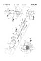
- FIG. 1is an isometric, exploded view of the invented drill bit showing its conical sectional tip end, hollow shaft region and locking end region, as well as a fragmentary view of the fitting which receives it.
- FIG. 2is a fragmentary view of the bit of FIG. 1 harvesting a donor bone region shown in cross section.
- FIG. 3is a fragmentary front elevation of the invented bit, and schematically illustrates certain of the important angular relationships of the tip's conical configuration and of the locking end region's and fitting's novel structures.
- FIG. 4is an end view of the invented bit that illustrates another of the important angular relationships of the tip's conical configuration.
- FIG. 5illustrates removal of the bit from the fitting by use of an invented hand tool.
- FIG. 6illustrates removal of harvested bone material from the bit by use of an invented hand tool.
- Distal and proximalare from the perspective of the drill or drilling machine to which the invented drill bit and fitting are fitted in use.
- proximalmeans relatively inwardly or nearer the drill's chuck and distal means relatively outwardly or farther therefrom.
- the invented drill bit's distal endperforms the harvesting work on the bone and its proximal end is affixed to the distal end of the fitting, the proximal end of which is affixed to the distal end of the drill's chuck.
- Drill bit 10preferably is formed with an elongate, cylindrical, hollow shank 12 having a proximal end with one or more, and preferably two, elongate slotted recesses formed therein for receiving therein a securing post of a drill head or chuck-and-fitting combination; and having on its distal end a semicircumferentially extending conical expanse defining a cutter, or cutting head or tip generally indicated at 14. As shown in FIG.
- cutting tip 14is provided with a first, sharpened or beveled, lip or edge 16 which joins in a sharp point 18 at the conical expanse's apex with another, non-sharpened lip or edge 20.
- Sharpened edge 16is configured to cut into bone, as shown in FIG. 2. More specifically, as shown in FIG. 2, when drill bit 10 is rotated in a clockwise direction (indicated by the arcuate arrow in FIG. 2), with point 18 directed against a section of bone 22, cutting edge 16 shears off fragments of bone 22 and deflects the fragments 22' through hollow shaft 12 toward its proximal end. As drill bit 10 is forced deeper inwardly of the donor bone, continuous cutting action occurs and a desired accumulation of morselized bone can then be removed from the shaft and used to build up bone in other areas to which it is transplanted.
- bit 10preferably it is machined out of stainless steel bar stock. After turning the piece and boring a distally extending central, axial bore therein, the cutting tip opening is formed, also by machining or by hand. When the drill bit has its basic shape, it is glass bead blasted to provide a bur-free, smooth finish. Drill bit 10 then is rendered corrosion-resistant by hardening it to approximately 38-42 Rockwell. Preferably such hardening is performed by heating the bit to approximately 875° F. for approximately one hour. Finally, the bit is resharpened to ensure that its cutting tip is capable. Persons of skill in the art will appreciate that alternative materials and processes may be used, within the spirit and scope of the invention.
- beveled (sharpened) cutting edge 16preferably extends from apex 18 through a substantially straight region that extends all the way to the periphery of shank 12 and terminates adjacent a region of joinder between conical expanse 24 and cylindrical shank 12 in a rectilinear notch or opening visibly depicted in FIG. 1 at 14a.
- This notchwhich may be seen to extend, or step, the cutting edge slightly proximally of the distal end of cylindrical shank 12, is believed to provide some chipping action as well as some directing action in terms of removing bone chips from the donor bone and collecting them in the hollow region of the shank.
- Notch 14ais an artifact of the manufacturing process by which the machined, smoothed and hardened stainless steel bit is re-machined either automatically or by hand, as by the use of a dovetail file, to ensure the sharpness of cutting edge 16.
- trailing edge 20has a smoothed arcuate feature (see FIG. 4) that also is an artifact of such final filing or machining step in the manufacture of invented drill bit. 10 but that has been rounded for aesthetic reasons.
- conical expanse 14 in cross sectionmay be seen to extend distally and inwardly (or toward the central long axis of the drill bit) at a predefined angle relative the long axis of shank 12.
- the angle between the distally, inwardly extending conical expanse 24 (and, most importantly, the inner surface thereof) relative to the long axis of shank 12preferably is between approximately 40° and 80° , more preferably is between approximately 45° and 75°, even more preferably is between approximately 50° and 70° and most preferably is approximately 60°.
- angles ⁇represent the angles between any straight line such as lines C 1 , C 2 extending along the conical expanse and intersecting at its apex, and the long axis A of shank 12.
- the sum of angles ⁇represents an obtuse, and preferably approximately 120° angle between opposite edges of conical expanse 24 represented by lines C 1 , C 2 .
- conical expanse 24extends partly circumferentially, or semicircumferentially.
- this semicircumferential expanseextends through an arc that is between approximately 120° and 240°, more preferably it extends through an arc that is between approximately 150° and 210° and most preferably it extends through an approximately 180° arc.
- This arcuate extent of the semicircumferential expanseis designated ⁇ in FIG. 4, which angle ⁇ represents the angle between a line D 1 marking leading or cutting edge 16 of conical expanse 24 of drill bit 10 and a line D 2 marking trailing or non-cutting edge 20 thereof.
- conical expanse 24extends represents an important tradeoff between the effective cutting capability and the effective collecting capability of the drill bit.
- the conical expansemight lack durability and might provide too little surface area for deflection of bone chips into shank 12.
- the conical expansemight produce too much frictional resistance to rotation and might complicate removal of harvested bone material from shank 12, a preferred means for which will be described by reference to FIG. 6.
- scores 26a, 26b, 26care calibrated preferably to indicate a linear depth measure from the outer extreme of cylindrical shank 12 (not counting the extent of the conical section cutting tip therebeyond), but it will be appreciated that they alternatively or additionally may indicate any useful measure such as material volume.
- each of recesses 28a, 28bpreferably includes a region extending distally spirally from the proximal end region 12a of shank 12, as best seen in FIGS. 1 and 3. Referring to FIG.
- recess 28a(and likewise diametrically opposed recess 28b) preferably extends at an angle ⁇ of between approximately 30° and 60° and more preferably at an angle of approximately 45° relative to the long axis of shank 12, which angle y is represented in FIG. 3 between axis B that parallels elongate recess 28a and long axis A of shank 12. It is believed that this angle ⁇ represents an optimal tradeoff between a slot extending in a plane normal to long axis A, which perhaps would best capture drill bit 10 within fitting 32, and a slot extending parallel to long axis A, which would provide adequate engagement for rotation but which would provide no security against inadvertent separation.
- FIGS. 1, 3 and 4show that shank 12 of drill bit 10 is in its proximal end region 12a preferably has a larger diameter than a distal end region 12b thereof.
- This step-wise diametric dimensional change along the length of shank 12provides for fitting of drill bit 10 to an adaptive fitting 32, yet permits its cutting head 14 to be suitably, and perhaps variably, sized for a specific bone-harvesting application.
- drill bit 10is approximately 85 mm long overall and fitting 32 is approximately 45 mm long overall, although of course other dimensions are within the spirit and scope of the invention.
- an array of bitsis provided having nominal outside right-cylindrical diameters (ODs) of 8 millimeters (8 mm), 10 mm and 12 mm, thereby providing for a variety of bone penetration diameters corresponding thereto, and thereby simplifying calculations of desired penetration depth for a given bone material volume requirement.
- ODsoutside right-cylindrical diameters
- proximal end region 12a at its greatest diameterpreferably is approximately 16 mm and the overall outer diameter of fitting 32 preferably is approximately 22 mm, although of course other suitable dimensions may be used depending upon the application.
- Fitting 32may be manufactured of any suitable material and by any suitable process, such as that described above for drill bit 10, and may have any suitable proximal end configuration that renders it matable with existing drill chucks. It will also be appreciated that the securing post by which bit 10 is securably gripped may be rendered in the drill chuck itself, thereby obviating fitting 32. Nevertheless, it is an advantage of the invention that fitting 32 is adaptable to mate novel drill bit 10 with any one of several industry-available drill chucks.
- a novel removal key 34may be provided to facilitate removal of drill bit 10 from fitting 32. It may seen from FIG. 5 that proximal end region 12a of shank 12 of bit 10 is tightly captured within fitting 32.
- This tight capture or securementmay be seen to be accomplished in accordance with invention in two ways: A split spring washer 36 is provided that is compressed around shank 12 and in interference fit within a circular detent 32aa formed within bore 32a of fitting 32; and a proximal region of the sidewall of each of two recesses 28a, 28b is in interference fit with crossbar member 30 within fitting 32.
- bit 10often is so securely fitted within fitting 32 that it cannot be easily removed by hand.
- FIG. 5may be seen to best illustrate use of the key to remove the bit from the fitting immediately prior to such manual leveraging action by the user.
- FIG. 5may be seen to best illustrate use of the key to remove the bit from the fitting immediately prior to such manual leveraging action by the user.
- fitting 32which may assume any desired configuration for mating with a custom drill chuck or any of a variety of industry-standard drill chucks. It is appreciated that fitting 32 serves the purpose in accordance with invention of coupling the novel bone-harvesting drill bit with the industry standard, installed base of medical drilling machines.
- Removal tool 38may be formed of a stiff cylindrical wire material, as shown. It may be formed at one end 38a into a loop that permits it to be digitally manipulated easily and perhaps hung on a peg. It may fixedly attach at another end a circular disk 38b of sufficiently small diameter and thickness to permit it to be introduced into an opening 14a of cutting end 14 of drill bit 10 and of sufficiently large diameter and thickness effectively to impinge upon, plunger- or piston-like, morselized bone material 22' to drive such bone material in a proximal direction out the proximal end region opening in drill bit 10. In this way, harvested bone material is readied for use in transplantation to a donee site.
- the iliac crest of the hip boneis used as a bone donor region for harvested bone, which in its granulated or morselized form is best for transplanting because it can be packed into another area where bone has been eroded, for example in an arthritic joint or other area in which bone has been diminished.
- the inventionmay be understood also to take the form of a method of harvesting bone from a donor site.
- the methodincludes 1) providing a bit 10 including a proximal hollow shank 12 and a distal cutter 14 including an opening to hollow shank 12, such opening being defined by a semicircumferentially extending conical expanse 24 having a point 18 at an apex thereof; 2) positioning bit 10 with such point 18 at a donor site of a bone 22; 3) rotating bit 10 at a defined speed, e.g. preferably approximately 200 revolutions per minute (RPM), with such cutter producing bone chips 22' and with such conical expanse 24 directing such produced bone chips 22' proximally through such opening into hollow shank 12; and 4) collecting such directed bone chips 22' in hollow shank 12 to produce a harvest of bone chips 22' therein for subsequent use.
- a defined speede.g. preferably approximately 200 revolutions per minute (RPM)
- the methodfurther includes providing fitting 32 for securely capturing a proximal terminal end of bit 10 therein and for fitting captured bit 10 to a drill for performing the rotating step.
- the methodfurther includes providing a hand tool such as removal key 34 for what will be referred to herein as snap-removing bit 10 from its secure capture within fitting 32, as is described and illustrated herein with reference to FIG. 5.
- the methodfurther includes providing a hand tool 38 for urging harvested bone chips 22' proximally within hollow shank 12 and out of an opening formed in an extreme proximal end of bit 10 for such use, as is described and illustrated herein with reference to FIG. 6.
- the invented methodfurther includes, preferably prior to such positioning step, inserting bit 10 into fitting 32 by urging the bit axially therealong.
- This inserting stepdue to the novel structure and cooperation of recesses 28a, 28b and crossbar member 30, results in relative rotation between bit 10 and fitting 32, with the rotation being effected by providing on either bit 10 or fitting 32 a cam such as crossbar member 30 of fitting 32 and by providing on the other of bit 10 and fitting 32 a follower such as diametrically opposed, oppositely inclined elongate recesses 28a, 28b in proximal end 12a of shank 12.
- the cam and followerwill be understood by those of skill in the art to cooperate to provide such rotation incident to the inserting step.
- alternative camming configurationsare possible, and are within the spirit and scope of the invention.
- the invented apparatusmay be seen to represent a significant improvement in a drill bit used in connection with bone grafting, the drill bit having a distal cutting tip and a proximal shank for rotation by a drill chuck.
- the improvementmight be characterized as including a hollow collector region 40 (see FIG. 2) formed within the drill bit's shank 12 for receiving and collecting bone chips 22' therein, and an opening 42 (see FIG. 2) to collector region 40, opening 42 being formed adjacent cutting tip 14.
- cutting tip 14is configured to produce bone chips such as bone chips 22' during rotation of drill bit 10 by the drill chuck and to deflect such produced bone chips 22' proximally into collector region 40. Such an improvement is perhaps best illustrated in FIG. 2.
- cutting tip 14preferably includes a semicircumferential conical expanse 24 terminating in a point 18 at the apex thereof, wherein the angle ⁇ between a line C 1 or C 2 that extends along the expanse and that intersects at the apex and long axis A of shank 12 preferably is between approximately 40° and 80°, more preferably is between approximately 50° and 70° and most preferably is approximately 60°.
- hollow collecting region 40extends through to the proximal terminal end of shank 12, thereby providing a convenient means for removal of collected bone chips 22', as, for example, by the use of plunger-like hand tool 38.
- improved drill bit 10is for use with a fitting 32 having a securing post such as crossbar member 30 within a bore 32a therein for receiving drill bit 10, wherein shank 12 has formed in the proximal terminal end thereof one or more, and preferably two, elongate slotted recesses 28a, 28b formed therein for receiving the securing post therein, wherein each of recesses 28a, 28b includes a region extending distally spirally from the shank's proximal terminal end, as perhaps best illustrated in FIGS. 1 and 3, and as described in detail above.
- a securing postsuch as crossbar member 30 within a bore 32a therein for receiving drill bit 10
- shank 12has formed in the proximal terminal end thereof one or more, and preferably two, elongate slotted recesses 28a, 28b formed therein for receiving the securing post therein, wherein each of recesses 28a, 28b includes a region extending distally spirally from the shank's prox
- the invented drill bit and the method for its use in harvesting boneprovides not only for producing bone chip material for grafting purposes, but conveniently also provides for collecting such bone chip material within the drill bit's hollow shaft.
- the invented drill bit and fittingconveniently and securely snap-fit together and may be easily snap-removed from one another and the harvested bone material removed from the bit's collecting region by the use, for example, of the invented hand tools.
Landscapes
- Health & Medical Sciences (AREA)
- Life Sciences & Earth Sciences (AREA)
- Surgery (AREA)
- Public Health (AREA)
- Molecular Biology (AREA)
- Veterinary Medicine (AREA)
- General Health & Medical Sciences (AREA)
- Animal Behavior & Ethology (AREA)
- Engineering & Computer Science (AREA)
- Biomedical Technology (AREA)
- Heart & Thoracic Surgery (AREA)
- Medical Informatics (AREA)
- Orthopedic Medicine & Surgery (AREA)
- Dentistry (AREA)
- Oral & Maxillofacial Surgery (AREA)
- Transplantation (AREA)
- Nuclear Medicine, Radiotherapy & Molecular Imaging (AREA)
- Hematology (AREA)
- Immunology (AREA)
- Rheumatology (AREA)
- Pathology (AREA)
- Surgical Instruments (AREA)
Abstract
Description
Claims (19)
Priority Applications (1)
| Application Number | Priority Date | Filing Date | Title |
|---|---|---|---|
| US08/389,115US5556399A (en) | 1995-02-14 | 1995-02-14 | Bone-harvesting drill apparatus and method for its use |
Applications Claiming Priority (1)
| Application Number | Priority Date | Filing Date | Title |
|---|---|---|---|
| US08/389,115US5556399A (en) | 1995-02-14 | 1995-02-14 | Bone-harvesting drill apparatus and method for its use |
Publications (1)
| Publication Number | Publication Date |
|---|---|
| US5556399Atrue US5556399A (en) | 1996-09-17 |
Family
ID=23536874
Family Applications (1)
| Application Number | Title | Priority Date | Filing Date |
|---|---|---|---|
| US08/389,115Expired - LifetimeUS5556399A (en) | 1995-02-14 | 1995-02-14 | Bone-harvesting drill apparatus and method for its use |
Country Status (1)
| Country | Link |
|---|---|
| US (1) | US5556399A (en) |
Cited By (94)
| Publication number | Priority date | Publication date | Assignee | Title |
|---|---|---|---|---|
| US5772664A (en)* | 1997-02-12 | 1998-06-30 | Wright Medical Technology, Inc. | Instrument for harvesting bone grafts having substantially cylindrical bone plugs |
| US5833628A (en)* | 1996-04-24 | 1998-11-10 | Yuan; Hansen | Graduated bone graft harvester |
| US5921987A (en)* | 1996-09-13 | 1999-07-13 | Depuy Orthopaedic Technology, Inc. | Articular cartilage transplant instrument set |
| US5954671A (en)* | 1998-04-20 | 1999-09-21 | O'neill; Michael J. | Bone harvesting method and apparatus |
| US6007496A (en)* | 1996-12-30 | 1999-12-28 | Brannon; James K. | Syringe assembly for harvesting bone |
| WO2000045712A1 (en)* | 1999-02-02 | 2000-08-10 | Synthes Ag Chur | Device for removing bone grafts |
| WO2000045713A1 (en) | 1999-02-02 | 2000-08-10 | Synthes Ag Chur | Device with a flexible shaft for removing bone grafts |
| US6110209A (en)* | 1997-08-07 | 2000-08-29 | Stone; Kevin R. | Method and paste for articular cartilage transplantation |
| WO2000056220A1 (en)* | 1999-03-19 | 2000-09-28 | Paul Cervi | Biopsy needle |
| US6193722B1 (en)* | 1998-09-29 | 2001-02-27 | Sulzer Orthopaedic Ag | Hollow milling tool |
| US6332886B1 (en) | 1999-02-03 | 2001-12-25 | Synthes (Usa) | Surgical reamer and method of using same |
| WO2002036022A1 (en)* | 2000-09-30 | 2002-05-10 | Coripharm Medizinprodukte Gmbh & Co. Kg | Surgical tool |
| US6575981B1 (en) | 1999-02-04 | 2003-06-10 | Sdgi Holdings, Inc. | Methods and instrumentation for vertebral interbody fusion |
| US6582437B2 (en) | 1999-08-26 | 2003-06-24 | Sdgi Holdings, Inc. | Devices and methods for implanting fusion cages |
| US20030176868A1 (en)* | 2002-02-22 | 2003-09-18 | Pepper John R. | Long bone reaming apparatus and method |
| US20030179975A1 (en)* | 2002-03-22 | 2003-09-25 | Bures Kenneth J. | Acousto-optic tunable filter with segmented acousto-optic interaction region |
| US6648895B2 (en) | 2000-02-04 | 2003-11-18 | Sdgi Holdings, Inc. | Methods and instrumentation for vertebral interbody fusion |
| US20040086347A1 (en)* | 2001-01-03 | 2004-05-06 | Peter Steer | Interchangeable holder for hollow drills |
| US6743234B2 (en) | 1999-02-04 | 2004-06-01 | Sdgi Holdings, Inc. | Methods and instrumentation for vertebral interbody fusion |
| WO2004093634A3 (en)* | 2003-04-21 | 2005-06-23 | Moshe Meller | Rotary apparatus for grafting and collecting bone |
| WO2005072625A3 (en)* | 2004-01-26 | 2005-09-09 | Vidacare Corp | Manual interosseous device |
| US20060015110A1 (en)* | 2004-07-15 | 2006-01-19 | Pepper John R | Cutting device |
| US20060177264A1 (en)* | 2005-02-09 | 2006-08-10 | Stryker Trauma S.A. | External mounting device, particularly for extension of a distance between clamping elements |
| US20070060935A1 (en)* | 2005-07-11 | 2007-03-15 | Schwardt Jeffrey D | Apparatus and methods of tissue removal within a spine |
| US20070100362A1 (en)* | 2005-11-02 | 2007-05-03 | Wenjie Deng | Powered surgical handpiece with improved latch mechanism and rotary to oscillating output drive |
| WO2007057928A1 (en)* | 2005-11-16 | 2007-05-24 | Physioline S.R.L. | Osseous scraper for drawing osseous flakes and/or shreds froma donor bone |
| US20080045861A1 (en)* | 2002-05-31 | 2008-02-21 | Miller Larry J | Medical Procedures Trays And Related Methods |
| US20080058674A1 (en)* | 2006-08-29 | 2008-03-06 | Lex Jansen | Tissue extraction device and method of using the same |
| US20080058673A1 (en)* | 2006-08-29 | 2008-03-06 | Lex Jansen | Tissue extraction device and method of using the same |
| WO2008033874A3 (en)* | 2006-09-12 | 2008-06-26 | Vidacare Corp | Bone marrow aspiration devices and related methods |
| WO2008033871A3 (en)* | 2006-09-12 | 2008-07-17 | Vidacare Corp | Apparatus and methods for biopsy and aspiration of bone marrow |
| US20080195106A1 (en)* | 2007-02-09 | 2008-08-14 | Sidebotham Christopher G | Modular spherical hollow reamer assembly for medical applications |
| US20080195105A1 (en)* | 2007-02-09 | 2008-08-14 | Sidebotham Christopher G | Low cost modular tapered hollow reamer for medical applications |
| US20080195104A1 (en)* | 2007-02-09 | 2008-08-14 | Sidebotham Christopher G | Modular tapered hollow reamer for medical applications |
| US20080195103A1 (en)* | 2007-02-09 | 2008-08-14 | Lawis Randall J | Hollow reamer for medical applications |
| US20080241206A1 (en)* | 2007-03-30 | 2008-10-02 | Constantz Brent R | Calcium phosphate cements comprising autologous bone |
| US7481814B1 (en)* | 2003-07-28 | 2009-01-27 | Biomet Manufacturing Corporation | Method and apparatus for use of a mill or reamer |
| US20090031871A1 (en)* | 2006-06-08 | 2009-02-05 | Malandain Hugues F | Dual cutting element tool for debulking bone |
| WO2008033872A3 (en)* | 2006-09-12 | 2009-04-30 | Vidacare Corp | Biopsy devices and related methods |
| US20090179368A1 (en)* | 2006-04-10 | 2009-07-16 | Franz Haimer | Means for preventing tools from being pulled out from tool holders with a tool holding fixture |
| US20090208903A1 (en)* | 2004-06-21 | 2009-08-20 | Straumann Holding Ag | Method for manufacturing disposable rotary cutting tools and disposable rotary tool for dental or medical applications |
| US20090264888A1 (en)* | 2008-04-22 | 2009-10-22 | Gebr. Brasseler Gmbh & Co. Kg | Bone graft drill |
| US7608079B1 (en) | 2004-03-05 | 2009-10-27 | Biomet Manufacturing Corp. | Unicondylar knee apparatus and system |
| US20090270893A1 (en)* | 2008-04-25 | 2009-10-29 | Greg Arcenio | Medical device for tissue disruption with serrated expandable portion |
| US20090270892A1 (en)* | 2008-04-25 | 2009-10-29 | Greg Arcenio | Steerable medical device for tissue disruption |
| US20090270862A1 (en)* | 2008-04-25 | 2009-10-29 | Greg Arcenio | Medical device with one-way rotary drive mechanism |
| US7670328B2 (en) | 2002-05-31 | 2010-03-02 | Vidacare Corporation | Apparatus and method to provide emergency access to bone marrow |
| US20100063507A1 (en)* | 2007-02-09 | 2010-03-11 | Sidebotham Christopher G | Low cost modular tapered and spherical hollow reamers for medical applications |
| US20100069907A1 (en)* | 2007-02-09 | 2010-03-18 | Sidebotham Christopher G | Modular tapered hollow reamer for medical applications |
| US7811260B2 (en) | 2002-05-31 | 2010-10-12 | Vidacare Corporation | Apparatus and method to inject fluids into bone marrow and other target sites |
| US7815642B2 (en) | 2004-01-26 | 2010-10-19 | Vidacare Corporation | Impact-driven intraosseous needle |
| US7951089B2 (en) | 2002-05-31 | 2011-05-31 | Vidacare Corporation | Apparatus and methods to harvest bone and bone marrow |
| US8142365B2 (en) | 2002-05-31 | 2012-03-27 | Vidacare Corporation | Apparatus and method for accessing the bone marrow of the sternum |
| US20120316566A1 (en)* | 2008-01-23 | 2012-12-13 | Osman Said G | Biologic Vertebral Reconstruction |
| USD679811S1 (en)* | 2010-04-28 | 2013-04-09 | Blue Belt Technologies, Llc | Tool shield |
| US8419683B2 (en) | 2004-11-12 | 2013-04-16 | Vidacare Corporation | Intraosseous device and methods for accessing bone marrow in the sternum and other target areas |
| US20130115023A1 (en)* | 2007-04-05 | 2013-05-09 | Franz Haimer Maschinenbau Kg | Tool Holder |
| US8641715B2 (en) | 2002-05-31 | 2014-02-04 | Vidacare Corporation | Manual intraosseous device |
| US8668698B2 (en) | 2002-05-31 | 2014-03-11 | Vidacare Corporation | Assembly for coupling powered driver with intraosseous device |
| US8690791B2 (en) | 2002-05-31 | 2014-04-08 | Vidacare Corporation | Apparatus and method to access the bone marrow |
| US8944069B2 (en) | 2006-09-12 | 2015-02-03 | Vidacare Corporation | Assemblies for coupling intraosseous (IO) devices to powered drivers |
| US8974410B2 (en) | 2006-10-30 | 2015-03-10 | Vidacare LLC | Apparatus and methods to communicate fluids and/or support intraosseous devices |
| US20150080896A1 (en) | 2013-07-19 | 2015-03-19 | Ouroboros Medical, Inc. | Anti-clogging device for a vacuum-assisted, tissue removal system |
| US9072543B2 (en) | 2002-05-31 | 2015-07-07 | Vidacare LLC | Vascular access kits and methods |
| US9216048B2 (en) | 2009-03-18 | 2015-12-22 | Integrated Spinal Concepts, Inc. | Image-guided minimal-step placement of screw into bone |
| CN105286944A (en)* | 2015-11-23 | 2016-02-03 | 浙江星月生物科技股份有限公司 | Novel hollow drill medical micro-fracture appliance |
| US9314228B2 (en) | 2002-05-31 | 2016-04-19 | Vidacare LLC | Apparatus and method for accessing the bone marrow |
| US9439667B2 (en) | 2002-05-31 | 2016-09-13 | Vidacare LLC | Apparatus and methods to install, support and/or monitor performance of intraosseous devices |
| US9451968B2 (en) | 2002-05-31 | 2016-09-27 | Vidacare LLC | Powered drivers, intraosseous devices and methods to access bone marrow |
| US9504477B2 (en) | 2003-05-30 | 2016-11-29 | Vidacare LLC | Powered driver |
| US9549743B2 (en) | 2013-05-14 | 2017-01-24 | Innospan Enterprises, Inc. | Bone graft harvesting device and method of use |
| US9579732B2 (en) | 2012-07-18 | 2017-02-28 | Milwaukee Electric Tool Corporation | Hole saw |
| US9833248B2 (en) | 2012-04-30 | 2017-12-05 | The John Hopkins University | Bone harvesting |
| US10368880B1 (en) | 2018-10-17 | 2019-08-06 | King Saud University | Universal base attachment bit and cutting bit assembly |
| US10448967B2 (en) | 2011-12-03 | 2019-10-22 | DePuy Synthes Products, Inc. | Discectomy kits with an obturator, guard cannula |
| WO2019245611A1 (en)* | 2018-06-22 | 2019-12-26 | In2Bones Usa, Llc | Bone graft harvester |
| CN111163713A (en)* | 2017-06-12 | 2020-05-15 | 康曼德公司 | Orthopedic drill bit with rotary head |
| US20200156163A1 (en)* | 2017-06-27 | 2020-05-21 | Hilti Aktiengesellschaft | Drill for Chiseling Stone |
| EP3578121A4 (en)* | 2017-01-31 | 2020-12-02 | Transell Co., Ltd. | PUNCTURING TOOL AND PUNCTURING DEVICE |
| US10973545B2 (en) | 2002-05-31 | 2021-04-13 | Teleflex Life Sciences Limited | Powered drivers, intraosseous devices and methods to access bone marrow |
| US10973532B2 (en) | 2002-05-31 | 2021-04-13 | Teleflex Life Sciences Limited | Powered drivers, intraosseous devices and methods to access bone marrow |
| US11000295B2 (en) | 2018-09-27 | 2021-05-11 | Acumed Llc | Bone harvesting system |
| US11148212B2 (en) | 2018-07-10 | 2021-10-19 | Milwaukee Electric Tool Corporation | Hole saw with hex sidewall holes |
| US11298202B2 (en) | 2002-05-31 | 2022-04-12 | Teleflex Life Sciences Limited | Biopsy devices and related methods |
| US11337728B2 (en) | 2002-05-31 | 2022-05-24 | Teleflex Life Sciences Limited | Powered drivers, intraosseous devices and methods to access bone marrow |
| USD956222S1 (en)* | 2020-08-21 | 2022-06-28 | Stryker European Operations Limited | Surgical bur assembly |
| USD958855S1 (en) | 2019-12-09 | 2022-07-26 | Milwaukee Electric Tool Corporation | Hole saw |
| US20220287693A1 (en)* | 2019-09-10 | 2022-09-15 | Lenkbar, Llc | Cutting head for tissue collection device |
| WO2022208036A1 (en)* | 2021-04-02 | 2022-10-06 | L'etat Français Représenté Par Le Ministère De L'intérieur | Device for taking samples of bone matter |
| US20220354469A1 (en)* | 2019-07-02 | 2022-11-10 | University Of Kentucky Research Foundation | Bone biopsy system and method |
| US11523834B1 (en) | 2022-06-20 | 2022-12-13 | University Of Utah Research Foundation | Cartilage and bone harvest and delivery system and methods |
| US11660194B1 (en) | 2022-06-20 | 2023-05-30 | University Of Utah Research Foundation | Cartilage and bone harvest and delivery system and methods |
| US12023047B1 (en) | 2023-07-14 | 2024-07-02 | University Of Utah Research Foundation | Cannulated trephine |
| US12059734B2 (en) | 2019-06-20 | 2024-08-13 | Milwaukee Electric Tool Corporation | Hole saw with circular sidewall openings |
Citations (8)
| Publication number | Priority date | Publication date | Assignee | Title |
|---|---|---|---|---|
| US14454A (en)* | 1856-03-18 | Moktisihg-tool | ||
| US77819A (en)* | 1868-05-12 | Charles krbbs | ||
| US469057A (en)* | 1892-02-16 | Reamer | ||
| US550190A (en)* | 1895-11-19 | Reamer-bit | ||
| US1493240A (en)* | 1923-02-15 | 1924-05-06 | Frank J Bohn | Surgical bone cutter and extractor |
| US1807126A (en)* | 1930-03-25 | 1931-05-26 | Byron F Morrill | Bit |
| US2710000A (en)* | 1952-02-19 | 1955-06-07 | Cromer Jeremiah Keith | Cutting instrument |
| US3112743A (en)* | 1960-09-01 | 1963-12-03 | Orthopaedic Specialties Corp | Method for treatment of bone fractures |
- 1995
- 1995-02-14USUS08/389,115patent/US5556399A/ennot_activeExpired - Lifetime
Patent Citations (8)
| Publication number | Priority date | Publication date | Assignee | Title |
|---|---|---|---|---|
| US14454A (en)* | 1856-03-18 | Moktisihg-tool | ||
| US77819A (en)* | 1868-05-12 | Charles krbbs | ||
| US469057A (en)* | 1892-02-16 | Reamer | ||
| US550190A (en)* | 1895-11-19 | Reamer-bit | ||
| US1493240A (en)* | 1923-02-15 | 1924-05-06 | Frank J Bohn | Surgical bone cutter and extractor |
| US1807126A (en)* | 1930-03-25 | 1931-05-26 | Byron F Morrill | Bit |
| US2710000A (en)* | 1952-02-19 | 1955-06-07 | Cromer Jeremiah Keith | Cutting instrument |
| US3112743A (en)* | 1960-09-01 | 1963-12-03 | Orthopaedic Specialties Corp | Method for treatment of bone fractures |
Cited By (219)
| Publication number | Priority date | Publication date | Assignee | Title |
|---|---|---|---|---|
| US5833628A (en)* | 1996-04-24 | 1998-11-10 | Yuan; Hansen | Graduated bone graft harvester |
| US5921987A (en)* | 1996-09-13 | 1999-07-13 | Depuy Orthopaedic Technology, Inc. | Articular cartilage transplant instrument set |
| US6007496A (en)* | 1996-12-30 | 1999-12-28 | Brannon; James K. | Syringe assembly for harvesting bone |
| US5772664A (en)* | 1997-02-12 | 1998-06-30 | Wright Medical Technology, Inc. | Instrument for harvesting bone grafts having substantially cylindrical bone plugs |
| US6110209A (en)* | 1997-08-07 | 2000-08-29 | Stone; Kevin R. | Method and paste for articular cartilage transplantation |
| US5954671A (en)* | 1998-04-20 | 1999-09-21 | O'neill; Michael J. | Bone harvesting method and apparatus |
| USRE40796E1 (en) | 1998-04-20 | 2009-06-23 | Paradigm Biodevices, Inc. | Bone harvesting method and apparatus |
| US6193722B1 (en)* | 1998-09-29 | 2001-02-27 | Sulzer Orthopaedic Ag | Hollow milling tool |
| WO2000045712A1 (en)* | 1999-02-02 | 2000-08-10 | Synthes Ag Chur | Device for removing bone grafts |
| WO2000045713A1 (en) | 1999-02-02 | 2000-08-10 | Synthes Ag Chur | Device with a flexible shaft for removing bone grafts |
| US6783532B2 (en) | 1999-02-02 | 2004-08-31 | Synthes (Usa) | Device for removing bone tissue |
| US6332886B1 (en) | 1999-02-03 | 2001-12-25 | Synthes (Usa) | Surgical reamer and method of using same |
| US7244258B2 (en) | 1999-02-04 | 2007-07-17 | Warsaw Orthopedic, Inc. | Methods and instrumentation for vertebral interbody fusion |
| US20070288007A1 (en)* | 1999-02-04 | 2007-12-13 | Burkus J K | Methods and instrument for vertebral interbody fusion |
| US6575981B1 (en) | 1999-02-04 | 2003-06-10 | Sdgi Holdings, Inc. | Methods and instrumentation for vertebral interbody fusion |
| US8579909B2 (en) | 1999-02-04 | 2013-11-12 | Warsaw Orthopedic, Inc | Methods and instrument for vertebral interbody fusion |
| US6743234B2 (en) | 1999-02-04 | 2004-06-01 | Sdgi Holdings, Inc. | Methods and instrumentation for vertebral interbody fusion |
| US20030195520A1 (en)* | 1999-02-04 | 2003-10-16 | Boyd Lawrence M. | Methods and instrumentation for vertebral interbody fusion |
| US20040176775A1 (en)* | 1999-02-04 | 2004-09-09 | Burkus J. Kenneth | Methods and instrumentation for vertebral interbody fusion |
| US20040024408A1 (en)* | 1999-02-04 | 2004-02-05 | Burkus J. Kenneth | Methods and instrumentation for vertebral interbody fusion |
| WO2000056220A1 (en)* | 1999-03-19 | 2000-09-28 | Paul Cervi | Biopsy needle |
| US6875183B2 (en) | 1999-03-19 | 2005-04-05 | Paul Laurence Cervi | Biopsy needle |
| US8083744B2 (en) | 1999-08-26 | 2011-12-27 | Warsaw Orthopedic, Inc. | Devices and methods for implanting fusion cages |
| US6719760B2 (en) | 1999-08-26 | 2004-04-13 | Sdgi Holdings, Inc. | Devices and methods for implanting fusion cages |
| US20040172037A1 (en)* | 1999-08-26 | 2004-09-02 | Dorchak John D. | Devices and methods for implanting fusion cages |
| US6723096B1 (en) | 1999-08-26 | 2004-04-20 | Sdgi Holdings, Inc. | Devices and methods for implanting fusion cages |
| US6582437B2 (en) | 1999-08-26 | 2003-06-24 | Sdgi Holdings, Inc. | Devices and methods for implanting fusion cages |
| US7316686B2 (en) | 1999-08-26 | 2008-01-08 | Warsaw Orthopedic, Inc. | Devices and methods for implanting fusion cages |
| US6648895B2 (en) | 2000-02-04 | 2003-11-18 | Sdgi Holdings, Inc. | Methods and instrumentation for vertebral interbody fusion |
| WO2002036022A1 (en)* | 2000-09-30 | 2002-05-10 | Coripharm Medizinprodukte Gmbh & Co. Kg | Surgical tool |
| US20040086347A1 (en)* | 2001-01-03 | 2004-05-06 | Peter Steer | Interchangeable holder for hollow drills |
| US7134815B2 (en)* | 2001-01-03 | 2006-11-14 | Bernd Schweiger | Interchangeable holder for hollow drills |
| US20030176868A1 (en)* | 2002-02-22 | 2003-09-18 | Pepper John R. | Long bone reaming apparatus and method |
| US20030179975A1 (en)* | 2002-03-22 | 2003-09-25 | Bures Kenneth J. | Acousto-optic tunable filter with segmented acousto-optic interaction region |
| US10512474B2 (en) | 2002-05-31 | 2019-12-24 | Teleflex Medical Devices S.À R.L. | Powered drivers, intraosseous devices and methods to access bone marrow |
| US9451968B2 (en) | 2002-05-31 | 2016-09-27 | Vidacare LLC | Powered drivers, intraosseous devices and methods to access bone marrow |
| US11291472B2 (en) | 2002-05-31 | 2022-04-05 | Teleflex Life Sciences Limited | Powered drivers, intraosseous devices and methods to access bone marrow |
| US11298202B2 (en) | 2002-05-31 | 2022-04-12 | Teleflex Life Sciences Limited | Biopsy devices and related methods |
| US20080045861A1 (en)* | 2002-05-31 | 2008-02-21 | Miller Larry J | Medical Procedures Trays And Related Methods |
| US11234683B2 (en) | 2002-05-31 | 2022-02-01 | Teleflex Life Sciences Limited | Assembly for coupling powered driver with intraosseous device |
| US11103282B1 (en) | 2002-05-31 | 2021-08-31 | Teleflex Life Sciences Limited | Powered drivers, intraosseous devices and methods to access bone marrow |
| US11103281B2 (en) | 2002-05-31 | 2021-08-31 | Teleflex Life Sciences Limited | Apparatus and methods to install, support and/or monitor performance of intraosseous devices |
| US11065382B2 (en) | 2002-05-31 | 2021-07-20 | Teleflex Life Sciences Limited | Apparatus to inject fluids into bone marrow and other target sites |
| US10973532B2 (en) | 2002-05-31 | 2021-04-13 | Teleflex Life Sciences Limited | Powered drivers, intraosseous devices and methods to access bone marrow |
| US10973545B2 (en) | 2002-05-31 | 2021-04-13 | Teleflex Life Sciences Limited | Powered drivers, intraosseous devices and methods to access bone marrow |
| US10893875B2 (en) | 2002-05-31 | 2021-01-19 | Teleflex Life Sciences Limited | Apparatus to access bone marrow |
| US10806491B2 (en) | 2002-05-31 | 2020-10-20 | Teleflex Life Sciences Limited | Vascular access kits and methods |
| US10595896B2 (en) | 2002-05-31 | 2020-03-24 | Teleflex Life Sciences Limited | Apparatus for accessing bone marrow including depth control mechanism |
| US11324521B2 (en) | 2002-05-31 | 2022-05-10 | Teleflex Life Sciences Limited | Apparatus and method to access bone marrow |
| US8641715B2 (en) | 2002-05-31 | 2014-02-04 | Vidacare Corporation | Manual intraosseous device |
| US10492830B2 (en) | 2002-05-31 | 2019-12-03 | Teleflex Medical Devices S.À R.L. | Penetrator assembly for accessing bone marrow |
| US10456149B2 (en) | 2002-05-31 | 2019-10-29 | Teleflex Medical Devices S.À R.L. | Apparatus and method to access bone marrow |
| US11337728B2 (en) | 2002-05-31 | 2022-05-24 | Teleflex Life Sciences Limited | Powered drivers, intraosseous devices and methods to access bone marrow |
| US10413282B2 (en) | 2002-05-31 | 2019-09-17 | Teleflex Medical Devices S.Àr.L. | Apparatus and methods to harvest bone and bone marrow |
| US10245010B2 (en) | 2002-05-31 | 2019-04-02 | Teleflex Medical Devices S.A.R.L | Assembly for coupling powered driver with intraosseous device |
| US8656929B2 (en) | 2002-05-31 | 2014-02-25 | Vidacare Corporation | Medical procedures trays and related methods |
| US10166332B2 (en) | 2002-05-31 | 2019-01-01 | Teleflex Medical Devices S.À R.L. | Apparatus to inject fluids into bone marrow and other target sites |
| US8506568B2 (en) | 2002-05-31 | 2013-08-13 | Vidacare Corporation | Apparatus and method to access bone marrow |
| US8668698B2 (en) | 2002-05-31 | 2014-03-11 | Vidacare Corporation | Assembly for coupling powered driver with intraosseous device |
| US10016217B2 (en) | 2002-05-31 | 2018-07-10 | Teleflex Medical Devices S.À.R.L. | Apparatus and methods to install, support and/or monitor performance of intraosseous devices |
| US9872703B2 (en) | 2002-05-31 | 2018-01-23 | Teleflex Medical Devices S.Àr.L. | Vascular access kits and methods |
| US9717847B2 (en) | 2002-05-31 | 2017-08-01 | Teleflex Medical Devices S.Àr.L. | Apparatus and method to inject fluids into bone marrow and other target sites |
| US9717564B2 (en)* | 2002-05-31 | 2017-08-01 | Teleflex Medical Devices S.À R.L. | Biopsy devices and related methods |
| US9545243B2 (en) | 2002-05-31 | 2017-01-17 | Vidacare LLC | Bone marrow aspiration devices and related methods |
| US7670328B2 (en) | 2002-05-31 | 2010-03-02 | Vidacare Corporation | Apparatus and method to provide emergency access to bone marrow |
| US8480632B2 (en) | 2002-05-31 | 2013-07-09 | Vidacare Corporation | Cartridge apparatus for injecting fluids into bone |
| US11266441B2 (en) | 2002-05-31 | 2022-03-08 | Teleflex Life Sciences Limited | Penetrator assembly for accessing bone marrow |
| US7699850B2 (en) | 2002-05-31 | 2010-04-20 | Vidacare Corporation | Apparatus and method to access bone marrow |
| US8684978B2 (en) | 2002-05-31 | 2014-04-01 | Vidacare Corporation | Apparatus and method to inject fluids into bone marrow and other target sites |
| US7811260B2 (en) | 2002-05-31 | 2010-10-12 | Vidacare Corporation | Apparatus and method to inject fluids into bone marrow and other target sites |
| US8690791B2 (en) | 2002-05-31 | 2014-04-08 | Vidacare Corporation | Apparatus and method to access the bone marrow |
| US7850620B2 (en)* | 2002-05-31 | 2010-12-14 | Vidacare Corporation | Biopsy devices and related methods |
| US9439667B2 (en) | 2002-05-31 | 2016-09-13 | Vidacare LLC | Apparatus and methods to install, support and/or monitor performance of intraosseous devices |
| US20110082387A1 (en)* | 2002-05-31 | 2011-04-07 | Miller Larry J | Biopsy Devices and Related Methods |
| US8715287B2 (en) | 2002-05-31 | 2014-05-06 | Vidacare Corporation | Apparatus and method to provide emergency access to bone marrow |
| US7951089B2 (en) | 2002-05-31 | 2011-05-31 | Vidacare Corporation | Apparatus and methods to harvest bone and bone marrow |
| US9393031B2 (en) | 2002-05-31 | 2016-07-19 | Vidacare LLC | Apparatus and method to provide emergency access to bone marrow |
| US9314270B2 (en) | 2002-05-31 | 2016-04-19 | Vidacare LLC | Apparatus and method to access bone marrow |
| US8038664B2 (en) | 2002-05-31 | 2011-10-18 | Vidacare Corporation | Apparatus and method to inject fluids into bone marrow and other target sites |
| US8876826B2 (en) | 2002-05-31 | 2014-11-04 | Vidacare Corporation | Apparatus and method to access bone marrow |
| US9314228B2 (en) | 2002-05-31 | 2016-04-19 | Vidacare LLC | Apparatus and method for accessing the bone marrow |
| US9295487B2 (en) | 2002-05-31 | 2016-03-29 | Vidacare LLC | Apparatus and method to inject fluids into bone marrow and other target sites |
| US8142365B2 (en) | 2002-05-31 | 2012-03-27 | Vidacare Corporation | Apparatus and method for accessing the bone marrow of the sternum |
| US8992535B2 (en) | 2002-05-31 | 2015-03-31 | Vidacare LLC | Apparatus and method to provide emergency access to bone marrow |
| US8308693B2 (en) | 2002-05-31 | 2012-11-13 | Vidacare Corporation | Bone penetrating needle with angled ports |
| US9078637B2 (en) | 2002-05-31 | 2015-07-14 | Vidacare LLC | Apparatus and methods to harvest bone and bone marrow |
| US9072543B2 (en) | 2002-05-31 | 2015-07-07 | Vidacare LLC | Vascular access kits and methods |
| WO2004093634A3 (en)* | 2003-04-21 | 2005-06-23 | Moshe Meller | Rotary apparatus for grafting and collecting bone |
| US9504477B2 (en) | 2003-05-30 | 2016-11-29 | Vidacare LLC | Powered driver |
| US10052111B2 (en) | 2003-05-30 | 2018-08-21 | Teleflex Medical Devices S.À R.L. | Powered driver |
| US7481814B1 (en)* | 2003-07-28 | 2009-01-27 | Biomet Manufacturing Corporation | Method and apparatus for use of a mill or reamer |
| CN101536926B (en)* | 2004-01-26 | 2012-07-18 | 维达保健公司 | Manual interosseous device |
| US8870872B2 (en) | 2004-01-26 | 2014-10-28 | Vidacare Corporation | Impact-driven intraosseous needle |
| US9433400B2 (en) | 2004-01-26 | 2016-09-06 | Vidacare LLC | Manual intraosseous device |
| US7815642B2 (en) | 2004-01-26 | 2010-10-19 | Vidacare Corporation | Impact-driven intraosseous needle |
| CN1913833B (en)* | 2004-01-26 | 2010-06-09 | 维达保健公司 | Manual intraosseous instrument |
| WO2005072625A3 (en)* | 2004-01-26 | 2005-09-09 | Vidacare Corp | Manual interosseous device |
| US7608079B1 (en) | 2004-03-05 | 2009-10-27 | Biomet Manufacturing Corp. | Unicondylar knee apparatus and system |
| US20090208299A1 (en)* | 2004-06-21 | 2009-08-20 | Straumann Holding Ag | Method for manufacturing disposable rotary cutting tools and disposable rotary tool for dental or medical applications |
| US20090208903A1 (en)* | 2004-06-21 | 2009-08-20 | Straumann Holding Ag | Method for manufacturing disposable rotary cutting tools and disposable rotary tool for dental or medical applications |
| US20110232073A1 (en)* | 2004-06-21 | 2011-09-29 | Straumann Holding Ag | Method for manufacturing disposable rotary cutting tools and disposable rotary tool for dental or medical applications |
| US8113833B2 (en)* | 2004-06-21 | 2012-02-14 | Straumann Holding, AG | Disposable rotary tool for dental or medical applications |
| US9770247B2 (en)* | 2004-06-21 | 2017-09-26 | Straumann Holding Ag | Method for manufacturing disposable rotary cutting tools and disposable rotary tool for dental or medical applications |
| US8438950B2 (en) | 2004-06-21 | 2013-05-14 | Straumann Holding Ag | Method for manufacturing disposable rotary cutting tools for dental or medical applications |
| US9962167B2 (en) | 2004-06-21 | 2018-05-08 | Straumann Holding Ag | Method for manufacturing disposable rotary cutting tools and disposable rotary tool for dental or medical applications |
| US20060015110A1 (en)* | 2004-07-15 | 2006-01-19 | Pepper John R | Cutting device |
| US8998848B2 (en) | 2004-11-12 | 2015-04-07 | Vidacare LLC | Intraosseous device and methods for accessing bone marrow in the sternum and other target areas |
| US8419683B2 (en) | 2004-11-12 | 2013-04-16 | Vidacare Corporation | Intraosseous device and methods for accessing bone marrow in the sternum and other target areas |
| US20060177264A1 (en)* | 2005-02-09 | 2006-08-10 | Stryker Trauma S.A. | External mounting device, particularly for extension of a distance between clamping elements |
| US7632271B2 (en)* | 2005-02-09 | 2009-12-15 | Stryker Trauma S.A. | External mounting device, particularly for extension of a distance between clamping elements |
| US20070060935A1 (en)* | 2005-07-11 | 2007-03-15 | Schwardt Jeffrey D | Apparatus and methods of tissue removal within a spine |
| US20070100362A1 (en)* | 2005-11-02 | 2007-05-03 | Wenjie Deng | Powered surgical handpiece with improved latch mechanism and rotary to oscillating output drive |
| US8137370B2 (en)* | 2005-11-02 | 2012-03-20 | Stryker Corporation | Powered surgical handpiece with improved latch mechanism and rotary to oscillating output drive |
| WO2007057928A1 (en)* | 2005-11-16 | 2007-05-24 | Physioline S.R.L. | Osseous scraper for drawing osseous flakes and/or shreds froma donor bone |
| US20090179368A1 (en)* | 2006-04-10 | 2009-07-16 | Franz Haimer | Means for preventing tools from being pulled out from tool holders with a tool holding fixture |
| EP2343144B1 (en) | 2006-04-10 | 2019-01-09 | Franz Haimer Maschinenbau KG | Means for preventing tools from being pulled out from tool holders with a tool holding fixture |
| US8505893B2 (en)* | 2006-04-10 | 2013-08-13 | Franz Haimer Maschinenbau Kg | Means for preventing tools from being pulled out from tool holders with a tool holding fixture |
| DE102006062973C5 (en)* | 2006-04-10 | 2020-03-05 | Franz Haimer Maschinenbau Kg | System of tool holder with a cylindrical tool holder in the form of a collet chuck and tool |
| US10933473B2 (en)* | 2006-04-10 | 2021-03-02 | Franz Haimer Maschinenbau Kg | Means for preventing tools from being pulled out from tool holders with a tool holding fixture |
| US20130328275A1 (en)* | 2006-04-10 | 2013-12-12 | Franz Haimei Maschinenbau KG | Means for Preventing Tools from Being Pulled Out from Tool Holders with a Tool Holding Fixture |
| US10898959B2 (en)* | 2006-04-10 | 2021-01-26 | Franz Haimer Maschinenbau Kg | Means for preventing tools from being pulled out from tool holders with a tool holding fixture |
| EP2343144A1 (en) | 2006-04-10 | 2011-07-13 | Franz Haimer Maschinenbau KG | Means for preventing tools from being pulled out from tool holders with a tool holding fixture |
| US20130307230A1 (en)* | 2006-04-10 | 2013-11-21 | Franz Haimer Maschinenbau Kg | Means for Preventing Tools from Being Pulled Out from Tool Holders with a Tool Holding Fixture |
| US20090031871A1 (en)* | 2006-06-08 | 2009-02-05 | Malandain Hugues F | Dual cutting element tool for debulking bone |
| US20080058673A1 (en)* | 2006-08-29 | 2008-03-06 | Lex Jansen | Tissue extraction device and method of using the same |
| US20080058674A1 (en)* | 2006-08-29 | 2008-03-06 | Lex Jansen | Tissue extraction device and method of using the same |
| US9510910B2 (en) | 2006-09-12 | 2016-12-06 | Vidacare LLC | Medical procedures trays and related methods |
| WO2008033871A3 (en)* | 2006-09-12 | 2008-07-17 | Vidacare Corp | Apparatus and methods for biopsy and aspiration of bone marrow |
| WO2008033873A3 (en)* | 2006-09-12 | 2008-07-17 | Vidacare Corp | Medical procedures trays and related methods |
| WO2008033872A3 (en)* | 2006-09-12 | 2009-04-30 | Vidacare Corp | Biopsy devices and related methods |
| WO2008033874A3 (en)* | 2006-09-12 | 2008-06-26 | Vidacare Corp | Bone marrow aspiration devices and related methods |
| US12089972B2 (en) | 2006-09-12 | 2024-09-17 | Teleflex Life Sciences Limited | Apparatus and methods for biopsy and aspiration of bone marrow |
| EP2066389A4 (en)* | 2006-09-12 | 2011-04-13 | Vidacare Corp | Bone marrow aspiration devices and related methods |
| US11426249B2 (en) | 2006-09-12 | 2022-08-30 | Teleflex Life Sciences Limited | Vertebral access system and methods |
| US8944069B2 (en) | 2006-09-12 | 2015-02-03 | Vidacare Corporation | Assemblies for coupling intraosseous (IO) devices to powered drivers |
| US10258783B2 (en) | 2006-10-30 | 2019-04-16 | Teleflex Medical Devices S.À R.L. | Apparatus and methods to communicate fluids and/or support intraosseous devices |
| US11583668B2 (en) | 2006-10-30 | 2023-02-21 | Teleflex Life Sciences Limited | Apparatus and methods to communicate fluids and/or support intraosseous devices |
| US12337132B2 (en) | 2006-10-30 | 2025-06-24 | Teleflex Life Sciences Ii Llc | Apparatus and methods to communicate fluids and/or support intraosseous devices |
| US8974410B2 (en) | 2006-10-30 | 2015-03-10 | Vidacare LLC | Apparatus and methods to communicate fluids and/or support intraosseous devices |
| US20080195106A1 (en)* | 2007-02-09 | 2008-08-14 | Sidebotham Christopher G | Modular spherical hollow reamer assembly for medical applications |
| US20080195105A1 (en)* | 2007-02-09 | 2008-08-14 | Sidebotham Christopher G | Low cost modular tapered hollow reamer for medical applications |
| US8403931B2 (en) | 2007-02-09 | 2013-03-26 | Christopher G. Sidebotham | Modular tapered hollow reamer for medical applications |
| US8535316B2 (en) | 2007-02-09 | 2013-09-17 | Randall J. Lewis | Hollow reamer for medical applications |
| US20080195104A1 (en)* | 2007-02-09 | 2008-08-14 | Sidebotham Christopher G | Modular tapered hollow reamer for medical applications |
| US8556897B2 (en) | 2007-02-09 | 2013-10-15 | Christopher G. Sidebotham | Modular spherical hollow reamer assembly for medical applications |
| US20080195103A1 (en)* | 2007-02-09 | 2008-08-14 | Lawis Randall J | Hollow reamer for medical applications |
| US8357163B2 (en) | 2007-02-09 | 2013-01-22 | Sidebotham Christopher G | Low cost modular tapered and spherical hollow reamers for medical applications |
| US8523866B2 (en) | 2007-02-09 | 2013-09-03 | Christopher G. Sidebotham | Modular tapered hollow reamer for medical applications |
| US20100069907A1 (en)* | 2007-02-09 | 2010-03-18 | Sidebotham Christopher G | Modular tapered hollow reamer for medical applications |
| US8449545B2 (en) | 2007-02-09 | 2013-05-28 | Christopher G. Sidebotham | Low cost modular tapered hollow reamer for medical applications |
| US20100063507A1 (en)* | 2007-02-09 | 2010-03-11 | Sidebotham Christopher G | Low cost modular tapered and spherical hollow reamers for medical applications |
| US7658940B2 (en) | 2007-03-30 | 2010-02-09 | Skeletal Kinetics, Llc | Calcium phosphate cements comprising autologous bone |
| US20080241206A1 (en)* | 2007-03-30 | 2008-10-02 | Constantz Brent R | Calcium phosphate cements comprising autologous bone |
| US20110004219A1 (en)* | 2007-03-30 | 2011-01-06 | Constantz Brent R | Calcium Phosphate Cements Comprising Autologous Bone |
| US11771439B2 (en) | 2007-04-04 | 2023-10-03 | Teleflex Life Sciences Limited | Powered driver |
| US20130115023A1 (en)* | 2007-04-05 | 2013-05-09 | Franz Haimer Maschinenbau Kg | Tool Holder |
| US11192194B2 (en)* | 2007-04-05 | 2021-12-07 | Franz Haimer Maschinenbau Kg | Tool holder |
| US9023048B2 (en)* | 2008-01-23 | 2015-05-05 | Amendia, Inc. | Biologic vertebral reconstruction |
| US9414929B2 (en) | 2008-01-23 | 2016-08-16 | Amendia, Inc. | Biologic vertebral reconstruction |
| US20120316566A1 (en)* | 2008-01-23 | 2012-12-13 | Osman Said G | Biologic Vertebral Reconstruction |
| US20090264888A1 (en)* | 2008-04-22 | 2009-10-22 | Gebr. Brasseler Gmbh & Co. Kg | Bone graft drill |
| EP2111805A1 (en)* | 2008-04-22 | 2009-10-28 | Gebr. Brasseler GmbH & Co. KG | Bone graft harvesting drill |
| US20090270893A1 (en)* | 2008-04-25 | 2009-10-29 | Greg Arcenio | Medical device for tissue disruption with serrated expandable portion |
| US20090270892A1 (en)* | 2008-04-25 | 2009-10-29 | Greg Arcenio | Steerable medical device for tissue disruption |
| US20090270862A1 (en)* | 2008-04-25 | 2009-10-29 | Greg Arcenio | Medical device with one-way rotary drive mechanism |
| US10603116B2 (en) | 2009-03-18 | 2020-03-31 | Integrated Spinal Concepts, Inc. | Image-guided minimal-step placement of screw into bone |
| US9216048B2 (en) | 2009-03-18 | 2015-12-22 | Integrated Spinal Concepts, Inc. | Image-guided minimal-step placement of screw into bone |
| US11471220B2 (en) | 2009-03-18 | 2022-10-18 | Integrated Spinal Concepts, Inc. | Image-guided minimal-step placement of screw into bone |
| US9687306B2 (en) | 2009-03-18 | 2017-06-27 | Integrated Spinal Concepts, Inc. | Image-guided minimal-step placement of screw into bone |
| USD679811S1 (en)* | 2010-04-28 | 2013-04-09 | Blue Belt Technologies, Llc | Tool shield |
| USD694406S1 (en) | 2010-04-28 | 2013-11-26 | Blue Belt Technologies, Llc | Tool shield |
| US10448967B2 (en) | 2011-12-03 | 2019-10-22 | DePuy Synthes Products, Inc. | Discectomy kits with an obturator, guard cannula |
| US10967437B2 (en) | 2011-12-27 | 2021-04-06 | Franz Haimer Maschinenbau Kg | Tool holder and clamping system |
| US9943912B2 (en) | 2011-12-27 | 2018-04-17 | Franz Haimer Maschinenbau Kg | Tool holder and method for producing a tool receiving portion for such a tool holder |
| US12193686B2 (en) | 2012-04-30 | 2025-01-14 | The Johns Hopkins University | Bone harvesting |
| US9833248B2 (en) | 2012-04-30 | 2017-12-05 | The John Hopkins University | Bone harvesting |
| US10086445B2 (en) | 2012-07-18 | 2018-10-02 | Milwaukee Electric Tool Corporation | Hole saw |
| US11084107B2 (en) | 2012-07-18 | 2021-08-10 | Milwaukee Electric Tool Corporation | Hole saw |
| US12343807B2 (en) | 2012-07-18 | 2025-07-01 | Milwaukee Electric Tool Corporation | Hole saw |
| USRE48513E1 (en) | 2012-07-18 | 2021-04-13 | Milwaukee Electric Tool Corporation | Hole saw |
| US10751811B2 (en) | 2012-07-18 | 2020-08-25 | Milwaukee Electric Tool Corporation | Hole saw |
| US9579732B2 (en) | 2012-07-18 | 2017-02-28 | Milwaukee Electric Tool Corporation | Hole saw |
| US11084108B2 (en) | 2012-07-18 | 2021-08-10 | Milwaukee Electric Tool Corporation | Hole saw |
| US11745273B2 (en) | 2012-07-18 | 2023-09-05 | Milwaukee Electric Tool Corporation | Hole saw |
| US9549743B2 (en) | 2013-05-14 | 2017-01-24 | Innospan Enterprises, Inc. | Bone graft harvesting device and method of use |
| US10342563B2 (en) | 2013-07-19 | 2019-07-09 | DePuy Synthes Products, Inc. | Anti-clogging device for a vacuum-assisted, tissue removal system |
| US20150080896A1 (en) | 2013-07-19 | 2015-03-19 | Ouroboros Medical, Inc. | Anti-clogging device for a vacuum-assisted, tissue removal system |
| CN105286944A (en)* | 2015-11-23 | 2016-02-03 | 浙江星月生物科技股份有限公司 | Novel hollow drill medical micro-fracture appliance |
| US12042176B2 (en) | 2017-01-31 | 2024-07-23 | Transell Co., Ltd. | Puncturing instrument and puncturing device |
| EP3854330A1 (en)* | 2017-01-31 | 2021-07-28 | Transell Co., Ltd. | Puncturing instrument and puncturing device |
| US11478273B2 (en) | 2017-01-31 | 2022-10-25 | Transell Co., Ltd. | Puncture instrument and puncture device |
| EP3578121A4 (en)* | 2017-01-31 | 2020-12-02 | Transell Co., Ltd. | PUNCTURING TOOL AND PUNCTURING DEVICE |
| CN111163713B (en)* | 2017-06-12 | 2023-06-09 | 康曼德公司 | Orthopaedics drill bit with rotary head |
| CN111163713A (en)* | 2017-06-12 | 2020-05-15 | 康曼德公司 | Orthopedic drill bit with rotary head |
| US20200156163A1 (en)* | 2017-06-27 | 2020-05-21 | Hilti Aktiengesellschaft | Drill for Chiseling Stone |
| US11691204B2 (en)* | 2017-06-27 | 2023-07-04 | Hilti Aktlengesellschaft | Drill for chiseling stone |
| US12390231B2 (en)* | 2018-06-22 | 2025-08-19 | In2Bones Usa, Llc | Bone graft harvester |
| WO2019245611A1 (en)* | 2018-06-22 | 2019-12-26 | In2Bones Usa, Llc | Bone graft harvester |
| US20220071641A1 (en)* | 2018-06-22 | 2022-03-10 | In2Bones Usa, Llc | Bone graft harvester |
| US11185339B2 (en) | 2018-06-22 | 2021-11-30 | In2Bones Usa, Llc | Bone graft harvester |
| US11148212B2 (en) | 2018-07-10 | 2021-10-19 | Milwaukee Electric Tool Corporation | Hole saw with hex sidewall holes |
| US12390866B2 (en) | 2018-07-10 | 2025-08-19 | Milwaukee Electric Tool Corporation | Hole saw with hex sidewall holes |
| US11845134B2 (en) | 2018-07-10 | 2023-12-19 | Milwaukee Electric Tool Corporation | Hole saw with hex sidewall holes |
| US11000295B2 (en) | 2018-09-27 | 2021-05-11 | Acumed Llc | Bone harvesting system |
| US11779350B2 (en) | 2018-09-27 | 2023-10-10 | Acumed Llc | Bone harvesting system |
| US10368880B1 (en) | 2018-10-17 | 2019-08-06 | King Saud University | Universal base attachment bit and cutting bit assembly |
| US12059734B2 (en) | 2019-06-20 | 2024-08-13 | Milwaukee Electric Tool Corporation | Hole saw with circular sidewall openings |
| US20220354469A1 (en)* | 2019-07-02 | 2022-11-10 | University Of Kentucky Research Foundation | Bone biopsy system and method |
| US20220287693A1 (en)* | 2019-09-10 | 2022-09-15 | Lenkbar, Llc | Cutting head for tissue collection device |
| USD958855S1 (en) | 2019-12-09 | 2022-07-26 | Milwaukee Electric Tool Corporation | Hole saw |
| USD1059442S1 (en) | 2019-12-09 | 2025-01-28 | Milwaukee Electric Tool Corporation | Hole saw |
| USD1006991S1 (en) | 2020-08-21 | 2023-12-05 | Stryker European Operations Limited | Surgical bur assembly |
| USD956222S1 (en)* | 2020-08-21 | 2022-06-28 | Stryker European Operations Limited | Surgical bur assembly |
| USD983970S1 (en) | 2020-08-21 | 2023-04-18 | Stryker European Operations Limited | Surgical bur assembly |
| FR3121342A1 (en)* | 2021-04-02 | 2022-10-07 | L'etat Français Représenté Par Le Ministère De L'intérieur | Bone collection device |
| WO2022208036A1 (en)* | 2021-04-02 | 2022-10-06 | L'etat Français Représenté Par Le Ministère De L'intérieur | Device for taking samples of bone matter |
| US11660194B1 (en) | 2022-06-20 | 2023-05-30 | University Of Utah Research Foundation | Cartilage and bone harvest and delivery system and methods |
| US11523834B1 (en) | 2022-06-20 | 2022-12-13 | University Of Utah Research Foundation | Cartilage and bone harvest and delivery system and methods |
| US12023047B1 (en) | 2023-07-14 | 2024-07-02 | University Of Utah Research Foundation | Cannulated trephine |
Similar Documents
| Publication | Publication Date | Title |
|---|---|---|
| US5556399A (en) | Bone-harvesting drill apparatus and method for its use | |
| US6162227A (en) | Bone cutter | |
| US4473070A (en) | Intramedullary reamer | |
| US11337709B2 (en) | Drill bit and method for producing a drill bit | |
| US4399813A (en) | Apparatus and method for removing a prosthesis embedded in skeletal bone | |
| US4649918A (en) | Bone core removing tool | |
| US8449545B2 (en) | Low cost modular tapered hollow reamer for medical applications | |
| US5693064A (en) | Dermal punch for hair transplantation and methods | |
| US8523866B2 (en) | Modular tapered hollow reamer for medical applications | |
| US5791902A (en) | Drill bit for producing bone cavities for dental implants | |
| US4345899A (en) | Dental twist drill | |
| US20060111724A1 (en) | Bone harvesting drill bit for oral surgery | |
| KR19990083369A (en) | Device removal kit and method therefor | |
| US8403931B2 (en) | Modular tapered hollow reamer for medical applications | |
| EP0141853A1 (en) | Method for reducing the incidence of wire breakage in orthopaedic surgery and the like and tools for effecting said method | |
| JPH04500771A (en) | Guide device for internal saw for cutting long bones | |
| US6004321A (en) | Cannulated screw retraction apparatus and method of retraction | |
| US10912573B2 (en) | Intramedullary canal reamer | |
| CN2036033U (en) | Whorl saw with bloch ring | |
| KR101416797B1 (en) | Bone harvester | |
| RU2251391C2 (en) | Cylindrical and conical bone cutters | |
| DE10048575A1 (en) | Surgical tool for removing bone and cartilage material and preparing bones for implantation has recesses between cutting teeth at end of hollow shaft | |
| AU2016244322B2 (en) | A drill bit and method for producing a drill bit | |
| RU34352U1 (en) | Core drill | |
| SU1337257A1 (en) | Tool for working stab wood |
Legal Events
| Date | Code | Title | Description |
|---|---|---|---|
| STCF | Information on status: patent grant | Free format text:PATENTED CASE | |
| AS | Assignment | Owner name:ACUMED, INC, OREGON Free format text:ASSIGNMENT OF ASSIGNORS INTEREST;ASSIGNOR:HUEBNER, RANDALL J.;REEL/FRAME:010052/0462 Effective date:19990421 | |
| FEPP | Fee payment procedure | Free format text:PAT HLDR NO LONGER CLAIMS SMALL ENT STAT AS INDIV INVENTOR (ORIGINAL EVENT CODE: LSM1); ENTITY STATUS OF PATENT OWNER: LARGE ENTITY | |
| FPAY | Fee payment | Year of fee payment:4 | |
| FEPP | Fee payment procedure | Free format text:PAYOR NUMBER ASSIGNED (ORIGINAL EVENT CODE: ASPN); ENTITY STATUS OF PATENT OWNER: LARGE ENTITY | |
| FPAY | Fee payment | Year of fee payment:8 | |
| AS | Assignment | Owner name:ACUMED OPERATING LLC, OREGON Free format text:CONTRIBUTION AGREEMENT;ASSIGNOR:ACUMED, INC.;REEL/FRAME:014662/0443 Effective date:20021209 | |
| AS | Assignment | Owner name:ACUMED LLC, OREGON Free format text:CHANGE OF NAME;ASSIGNOR:ACUMED OPERATING LLC;REEL/FRAME:014669/0179 Effective date:20021210 | |
| FPAY | Fee payment | Year of fee payment:12 |