US5555618A - Method of making electrode-carrying catheter - Google Patents
Method of making electrode-carrying catheterDownload PDFInfo
- Publication number
- US5555618A US5555618AUS08/355,663US35566394AUS5555618AUS 5555618 AUS5555618 AUS 5555618AUS 35566394 AUS35566394 AUS 35566394AUS 5555618 AUS5555618 AUS 5555618A
- Authority
- US
- United States
- Prior art keywords
- core
- wires
- ribbon
- wound
- wound wires
- Prior art date
- Legal status (The legal status is an assumption and is not a legal conclusion. Google has not performed a legal analysis and makes no representation as to the accuracy of the status listed.)
- Expired - Lifetime
Links
- 238000004519manufacturing processMethods0.000titleclaimsdescription13
- 229920003023plasticPolymers0.000claimsabstractdescription29
- 239000004033plasticSubstances0.000claimsabstractdescription29
- 238000004891communicationMethods0.000claimsabstractdescription12
- 238000000034methodMethods0.000claimsdescription34
- 238000002788crimpingMethods0.000claimsdescription24
- 239000000853adhesiveSubstances0.000claimsdescription16
- 230000001070adhesive effectEffects0.000claimsdescription16
- 238000009413insulationMethods0.000claimsdescription11
- 238000003466weldingMethods0.000claimsdescription10
- 229920002635polyurethanePolymers0.000claimsdescription9
- 239000004814polyurethaneSubstances0.000claimsdescription9
- 238000004804windingMethods0.000claimsdescription8
- 238000010438heat treatmentMethods0.000claimsdescription6
- 238000005452bendingMethods0.000claimsdescription5
- 238000010292electrical insulationMethods0.000claimsdescription5
- 229910001220stainless steelInorganic materials0.000claimsdescription5
- 239000010410layerSubstances0.000description119
- 208000027418Wounds and injuryDiseases0.000description62
- 238000000227grindingMethods0.000description10
- 239000002184metalSubstances0.000description8
- 229910052751metalInorganic materials0.000description8
- BASFCYQUMIYNBI-UHFFFAOYSA-NplatinumChemical compound[Pt]BASFCYQUMIYNBI-UHFFFAOYSA-N0.000description6
- 239000004593EpoxySubstances0.000description5
- 239000000463materialSubstances0.000description5
- 239000003973paintSubstances0.000description4
- 238000005520cutting processMethods0.000description3
- PCHJSUWPFVWCPO-UHFFFAOYSA-NgoldChemical compound[Au]PCHJSUWPFVWCPO-UHFFFAOYSA-N0.000description3
- 230000001965increasing effectEffects0.000description3
- 229910052697platinumInorganic materials0.000description3
- RYGMFSIKBFXOCR-UHFFFAOYSA-NCopperChemical compound[Cu]RYGMFSIKBFXOCR-UHFFFAOYSA-N0.000description2
- JOYRKODLDBILNP-UHFFFAOYSA-NEthyl urethaneChemical compoundCCOC(N)=OJOYRKODLDBILNP-UHFFFAOYSA-N0.000description2
- 210000004204blood vesselAnatomy0.000description2
- 229910052802copperInorganic materials0.000description2
- 239000010949copperSubstances0.000description2
- 230000003292diminished effectEffects0.000description2
- 239000012467final productSubstances0.000description2
- 229910052737goldInorganic materials0.000description2
- 239000010931goldSubstances0.000description2
- 238000009499grossingMethods0.000description2
- 238000013507mappingMethods0.000description2
- 238000012545processingMethods0.000description2
- 239000000047productSubstances0.000description2
- 238000000926separation methodMethods0.000description2
- 239000002356single layerSubstances0.000description2
- 239000010963304 stainless steelSubstances0.000description1
- DSUFPYCILZXJFF-UHFFFAOYSA-N4-[[4-[[4-(pentoxycarbonylamino)cyclohexyl]methyl]cyclohexyl]carbamoyloxy]butyl n-[4-[[4-(butoxycarbonylamino)cyclohexyl]methyl]cyclohexyl]carbamateChemical compoundC1CC(NC(=O)OCCCCC)CCC1CC1CCC(NC(=O)OCCCCOC(=O)NC2CCC(CC3CCC(CC3)NC(=O)OCCCC)CC2)CC1DSUFPYCILZXJFF-UHFFFAOYSA-N0.000description1
- 229910001369BrassInorganic materials0.000description1
- 229920001651CyanoacrylatePolymers0.000description1
- MWCLLHOVUTZFKS-UHFFFAOYSA-NMethyl cyanoacrylateChemical compoundCOC(=O)C(=C)C#NMWCLLHOVUTZFKS-UHFFFAOYSA-N0.000description1
- 229920002614Polyether block amidePolymers0.000description1
- 229910000589SAE 304 stainless steelInorganic materials0.000description1
- 208000001871TachycardiaDiseases0.000description1
- 206010068149Vessel perforationDiseases0.000description1
- 238000005299abrasionMethods0.000description1
- 230000036592analgesiaEffects0.000description1
- 238000000137annealingMethods0.000description1
- 230000015572biosynthetic processEffects0.000description1
- 239000010951brassSubstances0.000description1
- 239000006227byproductSubstances0.000description1
- 238000013153catheter ablationMethods0.000description1
- 238000010276constructionMethods0.000description1
- 238000001816coolingMethods0.000description1
- 229920001577copolymerPolymers0.000description1
- 230000003247decreasing effectEffects0.000description1
- 238000005553drillingMethods0.000description1
- 230000002708enhancing effectEffects0.000description1
- 230000001747exhibiting effectEffects0.000description1
- 238000001125extrusionMethods0.000description1
- 208000014674injuryDiseases0.000description1
- 238000007689inspectionMethods0.000description1
- 230000000873masking effectEffects0.000description1
- 239000000155meltSubstances0.000description1
- 238000012986modificationMethods0.000description1
- 230000004048modificationEffects0.000description1
- 229920000728polyesterPolymers0.000description1
- 229920000915polyvinyl chloridePolymers0.000description1
- 238000007639printingMethods0.000description1
- KCTAWXVAICEBSD-UHFFFAOYSA-Nprop-2-enoyloxy prop-2-eneperoxoateChemical groupC=CC(=O)OOOC(=O)C=CKCTAWXVAICEBSD-UHFFFAOYSA-N0.000description1
- 238000011084recoveryMethods0.000description1
- 239000007787solidSubstances0.000description1
- 239000010935stainless steelSubstances0.000description1
- 230000006794tachycardiaEffects0.000description1
- 230000001225therapeutic effectEffects0.000description1
- 230000008733traumaEffects0.000description1
- 230000005428wave functionEffects0.000description1
Images


Classifications
- A—HUMAN NECESSITIES
- A61—MEDICAL OR VETERINARY SCIENCE; HYGIENE
- A61B—DIAGNOSIS; SURGERY; IDENTIFICATION
- A61B18/00—Surgical instruments, devices or methods for transferring non-mechanical forms of energy to or from the body
- A61B18/04—Surgical instruments, devices or methods for transferring non-mechanical forms of energy to or from the body by heating
- A61B18/12—Surgical instruments, devices or methods for transferring non-mechanical forms of energy to or from the body by heating by passing a current through the tissue to be heated, e.g. high-frequency current
- A61B18/14—Probes or electrodes therefor
- A61B18/1492—Probes or electrodes therefor having a flexible, catheter-like structure, e.g. for heart ablation
- A—HUMAN NECESSITIES
- A61—MEDICAL OR VETERINARY SCIENCE; HYGIENE
- A61B—DIAGNOSIS; SURGERY; IDENTIFICATION
- A61B5/00—Measuring for diagnostic purposes; Identification of persons
- A61B5/24—Detecting, measuring or recording bioelectric or biomagnetic signals of the body or parts thereof
- A61B5/25—Bioelectric electrodes therefor
- A61B5/279—Bioelectric electrodes therefor specially adapted for particular uses
- A61B5/28—Bioelectric electrodes therefor specially adapted for particular uses for electrocardiography [ECG]
- A61B5/283—Invasive
- A61B5/287—Holders for multiple electrodes, e.g. electrode catheters for electrophysiological study [EPS]
- A—HUMAN NECESSITIES
- A61—MEDICAL OR VETERINARY SCIENCE; HYGIENE
- A61N—ELECTROTHERAPY; MAGNETOTHERAPY; RADIATION THERAPY; ULTRASOUND THERAPY
- A61N1/00—Electrotherapy; Circuits therefor
- A61N1/02—Details
- A61N1/04—Electrodes
- A61N1/05—Electrodes for implantation or insertion into the body, e.g. heart electrode
- A61N1/056—Transvascular endocardial electrode systems
- A—HUMAN NECESSITIES
- A61—MEDICAL OR VETERINARY SCIENCE; HYGIENE
- A61B—DIAGNOSIS; SURGERY; IDENTIFICATION
- A61B18/00—Surgical instruments, devices or methods for transferring non-mechanical forms of energy to or from the body
- A61B2018/00053—Mechanical features of the instrument of device
- A61B2018/00107—Coatings on the energy applicator
- A61B2018/00148—Coatings on the energy applicator with metal
- A—HUMAN NECESSITIES
- A61—MEDICAL OR VETERINARY SCIENCE; HYGIENE
- A61B—DIAGNOSIS; SURGERY; IDENTIFICATION
- A61B18/00—Surgical instruments, devices or methods for transferring non-mechanical forms of energy to or from the body
- A61B2018/00315—Surgical instruments, devices or methods for transferring non-mechanical forms of energy to or from the body for treatment of particular body parts
- A61B2018/00345—Vascular system
- A61B2018/00351—Heart
- A61B2018/00357—Endocardium
- A—HUMAN NECESSITIES
- A61—MEDICAL OR VETERINARY SCIENCE; HYGIENE
- A61B—DIAGNOSIS; SURGERY; IDENTIFICATION
- A61B18/00—Surgical instruments, devices or methods for transferring non-mechanical forms of energy to or from the body
- A61B2018/00571—Surgical instruments, devices or methods for transferring non-mechanical forms of energy to or from the body for achieving a particular surgical effect
- A61B2018/00577—Ablation
- A—HUMAN NECESSITIES
- A61—MEDICAL OR VETERINARY SCIENCE; HYGIENE
- A61B—DIAGNOSIS; SURGERY; IDENTIFICATION
- A61B18/00—Surgical instruments, devices or methods for transferring non-mechanical forms of energy to or from the body
- A61B18/04—Surgical instruments, devices or methods for transferring non-mechanical forms of energy to or from the body by heating
- A61B18/12—Surgical instruments, devices or methods for transferring non-mechanical forms of energy to or from the body by heating by passing a current through the tissue to be heated, e.g. high-frequency current
- A61B18/1206—Generators therefor
- A61B2018/1246—Generators therefor characterised by the output polarity
- A61B2018/1253—Generators therefor characterised by the output polarity monopolar
- Y—GENERAL TAGGING OF NEW TECHNOLOGICAL DEVELOPMENTS; GENERAL TAGGING OF CROSS-SECTIONAL TECHNOLOGIES SPANNING OVER SEVERAL SECTIONS OF THE IPC; TECHNICAL SUBJECTS COVERED BY FORMER USPC CROSS-REFERENCE ART COLLECTIONS [XRACs] AND DIGESTS
- Y10—TECHNICAL SUBJECTS COVERED BY FORMER USPC
- Y10T—TECHNICAL SUBJECTS COVERED BY FORMER US CLASSIFICATION
- Y10T29/00—Metal working
- Y10T29/49—Method of mechanical manufacture
- Y10T29/49002—Electrical device making
- Y10T29/49117—Conductor or circuit manufacturing
Definitions
- the present inventionrelates to electrode-carrying catheters, and more particularly to an inexpensive and reliable electrode-carrying catheter and a method of making the same.
- Electrode-carrying cathetersare well known in the medical art and find diagnostic and therapeutic utility in a wide variety of different applications.
- mapping cathetersare used diagnostically to produce a wave function of the heart's electrical impulses so that a doctor can determine proper functioning or fault, and location of the fault, in the heart.
- Ablative cathetersare used therapeutically to destroy tissue in the heart causing tachycardia, utilizing radio frequency current catheter ablation.
- Such cathetersare also used for heart pacing purposes and for analgesia in various parts of the body.
- the use of a plurality of smaller electrodes rather than a single large electrodefrequently enables superior electrical contact with the tissue, this being a highly desirable factor in connection with mapping catheters in particular.
- Electrode wireshave never proven to be entirely satisfactory as the electrodes since a functional electrode requires a much larger surface area than can be provided by a flexible wire. Further, unless provisions are made to fix the wire relative to the catheter tubing, it is extremely difficult to ensure that the wire is held in place so as to assure a reliable electrical contact. While a wire could be held in place by use of an electrically conductive adhesive securing the wire to the tubing, it would be extremely difficult to create an electrode by applying an adhesive in a thin layer over a large surface area, as would be necessary to ensure that the electrode layer is flexible.
- a biocompatible conductive paint as an electrodehas the advantage of being easily applied in an extremely thin layer to the tubing outer surface by printing techniques, so as to ensure flexibility thereof and cover the wire, there are other problems associated with such conductive paint. While the flexible, thin layer of conductive ink painted on the tubing outer surface forms a good "electrical" connection with the wire, the conductive paint does not form a reliable "physical" connection with the wire, as necessary to ensure that the passage of the catheter through the human body along the guidewire to the proposed working site does not to some degree remove, separate or abrade away the thin layer of conductive paint.
- electrode-carrying cathetersare made by applying metal strips on the outer side and/or distal (front) surfaces of a flexible tubing of non-conductive plastic, each side strip acting as a side or ring electrode and each distal strip acting as an end electrode.
- the presence of the metal stripslimits the natural flexibility of the tubing so that the catheter is not of high flexibility throughout its entire length, and this presents problems in threading the catheter into the human body over a guidewire since the diminished flexibility may limit the ability of the catheter to conform to the travel path defined by the guidewire, leading to blood vessel trauma. Nonetheless, such catheters carrying ring electrodes are in favor because of the high level of reliability of the electrical connections therein.
- the conventional processes for forming ring or metal band electrodes flush with the outer surface of a catheterare arduous, time-consuming and/or require further processing.
- metal bands and sleeves therebetweenare slipped over the tubing outer surface with the sleeves maintaining the appropriate spacing between adjacent electrodes; this requires the use of additional pieces (namely, the sleeves) and an arduous assembly process.
- Another processrequires the tubing to be stretched to lower the outer diameter thereof, metal bands placed over the stretched tubing and disposed in appropriate spatial relationship, and the tubing then heated and released. The metal bands sink into the heat-softened tubing outer surface as the tubing resumes its original configuration (except where the metal bands are embedded therein). This technique requires additional stretching, heating and cooling steps.
- the ring electrodesare commonly 0.040 or 0.080 inch in width and composed of the relatively expensive materials gold or platinum. Where a single catheter contains several ring electrodes, clearly the catheter is a relatively expensive device. Further, any placement of a large number of ring electrodes on the catheter results in a catheter which is stiff and difficult to place, thereby presenting an increased risk of blood vessel perforation. As there is but a single layer of wound wires extending from the proximal end of the catheter to the several ring electrodes, the number of ring electrodes borne by a catheter is strictly limited to 6 or so.
- an object of the present inventionto provide an electrode-carrying catheter which does not utilize ring electrodes.
- Another objectis to provide in one embodiment such a catheter which provides a large number of side electrodes economically and without stiffening.
- a further objectis to provide such a catheter which in one embodiment has layers of embedded wound wires.
- an electrode-carrying catheter(without ring electrodes) of low cost and high reliability, comprising elongate flexible tubing defining a proximal end, a distal end, and an electrically insulative outer tubular layer intermediate the ends.
- the tubingincludes a flexible, optionally electrically conductive, core of wire and a flexible non-conductive core-covering layer of plastic about the core.
- At least one electrically conductive electrodeis disposed at least partially on the outer tubular surface.
- Conducting meansare provided for conducting electrical signals between the proximal end and each of the electrodes.
- the conducting meansincludes, intermediate the core and the outer tubular layer, a longitudinally-spaced plurality of flexible electrically conductive wires helically wound around and at least partially into the core-covering layer and insulated from one another at least by the core-covering layer and from the environment at least by the outer tubular layer.
- the outer tubular layer, the core-covering layer and any electrical insulation about the wound wiresdefine a removed section about a segment of each of the electrodes to enable electrical contact between a respective one of the wound wires and a respective one of the electrodes.
- Each of the electrodesis in the form of an electrically conductive flexible flat means for providing electrical communication with a respective one of the wound wires.
- Each of the flat meansis electrically and physically joined to a respective one of the wound wires, and wrapped about and crimped onto the outer tubular layer.
- the coreis a stranded configuration of stress-relieved stainless steel wire having an appreciable torsional strength and a slow return after lateral bending.
- the core-covering layer and the outer tubular layerare formed of polyurethane. At least during the wire winding step, the core-covering layer is softer than the outer tubular layer.
- the core-covering layeris over-extruded over the core, and the outer tubular layer is over-extruded over the wound wires and the core-covering layer. Where each of the wound wires is covered with electrical insulation, the electrical insulation covering each wound wire defines a removed section beneath one of the electrodes.
- the preferred flat meansis a flat copper ribbon having a pair of opposed ends, the ribbon being electrically and physically joined at one end to a respective one of the wound wires (at its exposed portion), wrapped under tension completely about the outer tubular layer, and physically joined at the other end to itself.
- the ribbonis preferably joined to the wound wires by welding.
- each ribbonis crimped onto the outer tubular layer at least 24 crimp points.
- the removed sectionsare filled with an elastically insulative adhesive such as epoxy.
- an electrically conductive end electrodeis crimped distally onto the core extension and is proximally crimped onto and radially flush with the outer tubular layer.
- the core-covering layerdefines at least an inner annulus and a co-axial outer annulus disposed radially outwardly of the inner annulus
- the plurality of wound wiresdefines an inner set of wound wires helically wound in one direction within the inner annulus and an outer set of wound wires helically wound in the opposite direction and disposed radially outwardly of the inner set.
- the plurality of electrodesdefines at least a proximal set of electrodes and a distal set of electrodes, the proximal set of electrodes and outer set of wound wires in the outer annulus being in electrical communication, and the distal set of electrodes and the inner set of wound wires in the inner annulus being in electrical communication.
- the catheterpreferably contains at least ten of the electrodes and is substantially flexible.
- the present inventionalso encompasses a process for manufacturing an electrode-carrying catheter of high reliability, comprising the step of over-extruding a core-covering layer of plastic over a flexible, optionally electrically conductive, elongate core of wire.
- a spaced apart plurality of flexible, electrically conductive wiresis helically wound about and at least partially into the soft outer layer.
- a flexible, non-conducting outer layer of plasticis over-extruded over the wound wires and the core-covering layer. Portions of the outer layer, the core-covering layer and any insulation about the wound wires are removed at a plurality of spaced locations so as to expose a portion of each of the wound wires.
- the removed portions at each locationare replaced with an electrically conductive, flexible, flat ribbon electrically and physically joined at one end to a respective one of the wound wires (at its exposed portion), wound under tension completely about the outer layer and physically joined at the other end to itself.
- the ribbonis then crimped onto the outer layer at each spaced location.
- the soft outer layerdefines at least an inner annulus and a co-axial outer annulus deposed radially outwardly of the inner annulus.
- the plurality of wound wiresdefines an inner set of wound wires helically wound in one direction within the inner annulus and an outer set of wound wires helically wound in the opposite direction and disposed radially outwardly of the inner set.
- the plurality of ribbon electrodesdefines at least a proximal set of ribbon electrodes and a distal set of ribbon electrodes, the proximal set of ribbon electrodes and the outer set of wound wires in the outer annulus being in electrical communication and the distal set of ribbon electrodes and the inner set of wound wires in the inner annulus being in electrical communication.
- the removed portionsare filled with an electrically insulative adhesive such as epoxy.
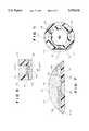
- FIG. 1is a fragmentary side elevational view of an electrode-bearing catheter according to a preferred embodiment of the present invention, with three side electrodes and one end electrode;
- FIG. 2is a fragmentary side elevational view of the tubing and wound wires thereof, partially in section and to a slightly enlarged scale;
- FIG. 3is a fragmentary sectional view taken along the line 3--3 of FIG. 2, to a greatly enlarged scale;
- FIGS. 4A--4Dare schematics illustrating the process of applying the flat ribbon electrode to the tubing
- FIG. 5is a transverse sectional view, to an enlarged scale, of the catheter after crimping of the ribbon electrodes thereon, with the crimps being greatly exaggerated for expository purposes;
- FIGS. 6 and 7are fragmentary longitudinal and transverse sectional views, respectively, of the catheter after the addition of adhesive, to a greatly enlarged scale;
- FIG. 8is a fragmentary exploded side elevational view of the catheter and end electrode assembly
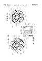
- FIG. 10is a transverse sectional view of a preferred embodiment of the catheter with two wire layers before window formation
- FIG. 11is a transverse sectional view thereof after application of a ribbon electrode, but before crimping.
- FIG. 12is a fragmentary sectional view taken along the line 12--12 of FIG. 11.
- the catheter 10is formed of elongate, flexible tubing generally designated 12.
- the tubing 12defines a proximal end 14, a distal end 16, and a sidewall or outer tubular layer 20 connecting the ends 14, 16 and having an electrically insulative outer surface 21.
- the electrodemay be a side electrode 30a disposed on the outer surface 21 (three side electrodes being illustrated in FIG. 1), an end electrode 30b disposed on the distal or front end 16 (one end electrode being illustrated in FIG. 1), or a combination thereof.
- the side electrodes 30aextend predominantly transversely (i.e., circumferentially) relative to the tubing axis.
- the side electrodes 30aextend fully around the circumference of the tubing 12, and the end electrode 30b extends over the full diameter of the distal end 16 (as illustrated).
- Conducting means, generally designated 29,are provided for conducting electrical signals between the proximal end 14 and each of the electrodes 30a, 30a, 30a, 30b.
- the tubing 12is composed initially of a flexible, conductive core 42 and a flexible, insulating, core-covering layer 44 disposed over the outer surface of the core 42. If there is an electrode 30b, the core 42 must be electrically conductive.
- the core 42is preferably formed of a wire exhibiting an appreciable degree of torsional stiffness (so that rotation of the proximal end 14 of the tubing is transmitted to the distal end 16) and a slow return or recovery after a lateral bending (so that the catheter makes good contact along its length with the walls of the vessel into which it is inserted).
- the core-covering layer 44may be formed by over-extruding (or otherwise forming) a plastic over the core 42.
- a preferred soft core-covering layer 44is formed of a soft plastic such as polyurethane having a durometer hardness of 80A available under the trade name Tecoflex (from Thermedics Inc. of Woburn, Mass.).
- a preferred hard core-covering layer 44is formed of a hard plastic such as polyurethane having a Shore durometer hardness of 75D available under the trade name Tecothane (also from Thermedics Inc.).
- the core-covering layer 44is preferably formed of an opaque plastic to facilitate viewing of the wires 45, by providing contrast.
- flexible, insulated, electrically conductive wires 45are helically or spirally wound around and at least partially into the core-covering layer 44 about the core 42.
- the wound wires 45are longitudinally spaced apart in a single layer such that each of the wires 45 is insulated from the two adjacent wires 45 by portions of the core-covering layer 44 as well as the wire insulation,
- the wires 45are helically or spirally wound around the layer 44 (under roughly hand tension) so that they at least partially embed themselves within the core-covering layer 44 (preferably at least 75% of the diameter becoming embedded).
- the wound wires 45are preferably insulated magnet wires having a gauge of 34. As the core-covering layer 44 ensures electrical separation between the various wires 45, the wires are not insulated in order to prevent shorting if they come into contact, but merely to facilitate subsequent processing steps. Indeed, uninsulated wires may be used if desired. It will be appreciated that, while only three wires 45 have been illustrated, the number of wires 45 can be varied as desired for particular applications depending on the number of side electrodes 30a. Each wire 45 (or the insulation thereon) is preferably of a different color so that the various wires in and about the core-covering layer 44 can be distinguished.
- the core-covering layer 44is formed of a soft plastic (e.g., Shore A hardness of 80), the hand tension exerted on the wires 45 during the winding step are sufficient to at least partially embed the wires 44 into the core-covering layer 44 (at least about 75% of the cross section of the wires being embedded).
- the core-covering layer 44is formed of a hard plastic (e.g., Shore D hardness of 75)
- the core-covering layer 44is preferably heated (e.g., by hot air guns) at the point where the wire contacts the layer 44, thereby to temporarily decrease the hardness of the hard plastic and allow the wire 45 to become embedded therein under simple hand tension.
- the use of a hard plastic for the core-covering layer 44is preferred because, once cooled, it better immobilizes the wires 45 and because it contributes to the torsional stiffness of the catheter 10.
- heating of the hard plastic to about 200° F.provides sufficient temporary softening of the plastic to enable the wires 45 to become embedded all the way into the core-covering layer 44.
- a flexible, thin insulating layer of plasticis over-extruded (or otherwise formed) over the core-covering layer 44 and any exposed portion of wound wires 45 to form the outer tubular layer 20 of the tubing 12 defining outer surface 21.
- the conductive wires 45are isolated from one other and the environment by means of the core 42, the core-covering layer 44, and the outer layer 20 as well as any insulation on the wires.
- the outer tubular layer 20may be formed of polyurethane or any of the other flexible, electrically insulative plastics commonly used in catheter construction such as polyvinyl chlorides, polyesters and various copolymers.
- the outer hard layer 20is preferably formed of polyurethane having a Shore D hardness of 71-75 available under the trade name Tecothane (from Thermedics Inc.). Where the core-covering layer is formed of hard plastic, the outer layer 20 is preferably formed of polyurethane having a Shore D hardness D of 63 available under the trade name Pebax (from Elf Atochem of Birdsboro, Pa.).
- the core-covering layer 44is formed of soft plastic, it may in the final product be softer than the outer layer 20, but that, when it is formed of hard plastic, it may in the final product be harder than the outer layer 20. This is true even though, during the winding process, the pertinent portions of the core-covering layer formed of hard plastic are temporarily softened by heating to allow embedding therein of the wires 45.
- the core-covering layer 44is of sufficient thickness to receive and electrically isolate the wound wires 45 (which must then be totally embedded therein) and is furthermore subsequently treatable (e.g., curable or modifiable) to provide an abrasion-resistant surface, application of the outer layer 20 may be dispensed with entirely and the core-covering layer 44, thus treated after the wires 45 are totally embedded therein, will also serve as the outer layer 20.
- treatablee.g., curable or modifiable
- the outer layer 20 and core-covering layer 44 of the tubing 12are removed at a plurality of spaced locations along its circumferential sidewall 21 (corresponding to the ultimate locations of the ribbon electrodes 51) so as to form windows 47.
- Each window 47exposes a portion of a respective one of the wound wires 45 at its respective location.
- the outer layer 20 and core-covering layer 44can be removed at the desired locations by various techniques such as cutting, skiving, drilling or grinding, but grinding or cutting is preferred as they are easy, quick and precise operations.
- the windowsare preferably formed using a grinding wheel having a diameter suitable for forming windows of the desired size (such as a 0.020 inch diameter) until the grinding has removed a suitable amount of the two layers 20, 44. Where present, the insulation about each wire 45 is also removed at one location so as to expose the conductive element of the wire 45.
- the outer layer 20 and the core-covering layer 44 at the distal end 16 of the tubing 12are removed (e.g., ground by a grinding wheel) and, where present, the insulation about the end of the core 42 is also removed. Grinding of the distal end 16 continues until there is exposed an appropriate length (about 0.035 inch) of the conductive element of the core wire 42, this exposed conductive element projecting forwardly from the distal end 16 of the tubing 12 as a core extension 42a.
- the two layers 20, 44 of the sidewall 21may have the portions at the particular locations removed therefrom simultaneously to form windows 47.
- the locations at which the layers 20, 44 are to be removedare predetermined by the desired location of the ribbon electrodes 30a.
- the wound wires 45are already in place and in fixed spatial disposition relative to one another. Accordingly, once the location of one wire 45 is determined (perhaps by inspection of the distal end 16 where they are initially visible), then the location of all of the remaining wires 45 is known.
- grinding elements of a grinding machinefor example, can be appropriately positioned relative to the known wire, and the desired portions of the layers 20, 44 (and, when present, the wire insulation) simultaneously removed at each location. This enables the windows 47 to be inexpensively formed in a low labor operation.
- a flat conductive element 51such as a flat copper ribbon (0.001 ⁇ 0.012 inch) is electrically and physically joined to the exposed portion of the wire 45 under the window 47.
- the ribbon 51is welded to the exposed wire 45 at point 48 using a welder such as that available under the trade name Light Force Welder (from Unitek Equipment Inc. of Monrovia, Calif.).
- a free ribbon end 51ais first welded to the wire 45.
- the ribbon 51 and the tubing 10are then rotated relative to one another until a shank 5lb of the ribbon 51 is wrapped essentially one turn (360°) about the outer layer 20, and back on itself.
- the tubing 12This may be accomplished by rotating the tubing 12 while using a machine to maintain hand tension on the ribbon 51.
- the as yet unwelded ribbon end 51c of the loop thus formedis welded to the ribbon 51 at point 49 (preferably at the already welded ribbon end 51a).
- the ribbon 51is removed from the ribbon spool (not shown), e.g., by simply applying a quick tug to the ribbon.
- the ribbonperforms the role of an electrode, bringing the signal from the exposed wire (which is located below the hard layer 20) up to the top of the outer tubular layer 20--i.e., up to the catheter outer surface.
- the welding equipmentuses the electrodes available under the trade name Unitip 111L (available from Unitek Equipment Inc.) or a similar microelectrode which permits the welding equipment to resistively weld the exposed wire 45 and the ribbon 51 together within the confines of window 47.
- the crimping machine and the catheter workpieceare then relatively rotated (e.g., 15°) and crimping is performed a second time (thus making, for example, 24 equidistantly spaced crimp points), thereby to flatten out any high spots left by the first crimping.
- the present inventionemploys a crimping process which offers a significant cost advantage over conventional processes for producing a catheter with a flush outer surface by sharply reducing labor requirements and simplifying assembly.
- the plastic of the outer layer 20may be heated slightly (to about 200° F.) to soften the same and facilitate crimping of the ribbon into the plastic.
- the ribbon 51may be welded to the wire 45.
- the weldingmay be performed using a conventional resistive welder with two electrodes which have been machined to the diameter of the ribbon 51 so that the welder cannot damage the same under the pressure of the weld.
- a preferred resistive welderis available under the trade name Thin Line Welder (from Unitek Equipment Inc.).
- the crimping operationresults in a catheter having a smooth outer surface except for the window 47. Because the ribbon ends 51a, 51c are disposed within the window 47, they are not crimped by the crimping operation and thus do not receive the extra measure of security which would be the result if they were crimped together and onto the exposed wire portion. Accordingly, referring now to FIGS. 6 and 7, it has been found desirable to fill in the remaining portion of each window 47 (that is, the portion not occupied by the ribbon ends 51a, 51c and the welds 48, 49) with an electrically insulative adhesive 70 such as epoxy or cyanoacrylate.
- an electrically insulative adhesive 70such as epoxy or cyanoacrylate.
- the manufacturing process of the present inventionis in all its aspects easy and inexpensive relative to the labor-intensive nature of most other manufacturing processes for producing an electrode-carrying catheter, while affording a product of enhanced reliability.
- the electrically conductive end electrodeis preferably configured and dimensioned as a flexible cap, generally designated 60, disposed across the distal end 16 of the tubing 12 in order to close the same.
- the cap 60may be formed of the same material as the ribbon 51 or a different material.
- the cap 60is of appreciable thickness and has a head 64 defining a recess 62 on its proximal surface and a proximally projecting circumferential band 66. As cap 60 is slipped over the distal end, the core extension 42a is received within cap recess 62, and the distal end of the outer layer 20 is received within the cap band 66. Referring now to FIG.
- the head or cap distal end 64is then crimped onto the core extension 42a, at 80, and the band or cap proximal end 66 is crimped onto and flush with the outer layer 20, at 82.
- This double crimping 80, 82using a crimping machine as described hereinabove in connection with the crimping of the ribbons 51, securely joins the end electrode 30b with the core extension 42a and hard layer 20, neither a ribbon 51 nor a welding step being required.
- the present inventionreduces both the cost of materials and the cost of production. As there is no necessity for the use of the standard 0.040 or 0.080 inch wide electrodes made of gold or platinum, the cost of materials is substantially diminished relative to the use of platinum or gold ring electrodes. Also, the labor cost involved in manufacturing the catheter is also decreased as the laborious and time-consuming step of threading the ring electrodes onto the tubing is no longer necessary.
- the catheter of the present inventionhas an extremely small proportion of metal on its surface relative to a like catheter with a like number of conventional electrodes on the surface thereof. As a result, the catheter maintains its flexibility even when a large number of ribbon electrodes are mounted thereon.
- conventional catheters with six or more ring electrodesare stiff, difficult to place, and involve increased risk of patient perforation.
- the present inventionpermits ten or more ribbon electrodes to be disposed on a still flexible catheter.
- the wound wiresare preferably embedded in multiple layers within the core-covering layer 44 of the catheter body rather than just one layer.
- the core-covering layer 44defines at least an inner annulus 44a and a co-axial outer annulus 44b disposed radially outwardly of the inner annulus 44a.
- the plurality of wound wires 45defines an inner set of wound wires 45a helically wound in one direction within the inner annulus, and an outer set of wound wires 45b helically wound in the opposite direction and disposed radially outwardly of the inner set 45a.
- the plurality of ribbon electrodes 51defines at least a proximal set of the electrodes and a distal set of the electrodes. The proximal set of electrodes and the outer set of wound wires 45b in the outer annulus 44b are in electrical communication, while the distal set of ribbon electrodes and the inner set of wound wires 45a in the inner annulus 44a are in electrical communication.
- the different wire layersare preferably helically wrapped in opposite directions--one layer clockwise helically and the other layer counterclockwise helically.
- the proximal set of electrodes and the outer set of wound wires 45b in the outer annulus 44bare electrically connected first, while the distal set of electrodes and the inner set of wound wires 45a in the inner annulus 44a are electrically connected subsequently.
- Thisenables the outer set of wound wires 45b to be cut, as necessary, to facilitate connecting of the inner set of wound wires 45a and the distal set of electrodes without affecting the previously made electrical connections with the proximal set of electrodes.
- a flexible, electrically conductive core 42 of stranded 7 ⁇ 19 stainless steel wire(0.018 inch diameter) is over-extruded with a soft, flexible, non-conductive core-covering opaque inner polyurethane jacket 44a (0.038 inch diameter and a Shore D hardness of 75).
- Four wires 45aare then spiral wrapped in the clockwise direction under tension so that they become at least partially and preferably totally embedded in the inner urethane jacket 44.
- a soft, flexible, non-conductive core-covering clear polyurethane jacket 44b(0.058 inch diameter and a Shore D hardness of 75) is then extruded over the wire-wrapped inner annulus, including jacket 44a and wires 45a, so as to allow the inner set of wires of 45a to be seen therethrough. Then five wires 45b are spirally wrapped in the counterclockwise direction under tension onto the outer urethane jacket 44b so that they become at least partially and preferably totally embedded in the outer jacket 44b.
- a transparent or translucent, electrically insulative outer tubular layer 20 (0.078 inch diameter) of plasticis extruded over the wire-wrapped outer annulus 44b, 45b. The resultant structure is illustrated in FIG. 10. It will be appreciated that the opaque inner jacket 44a provides a dark background against which the wires 45b in the clear outer jacket 44b may be discerned.
- the end electrode 30bmay be formed by stripping the distal end of the catheter down to the core 42 and allowing about a short length (0.042 inch) of stranded cable 42 to protrude distally as the extension 42a. A gold-plated brass tip electrode 60 is then double crimped onto the core extension 42a.
- the outer tubular layer 20 and portions of the outer annulus 44bare ground or cut away at the proximal end portion of the tubing 12 to form a window 47 and expose a portion of each of the outer set of wound wires 45b in the outer annulus 44b.
- the end 51a of each gold-plated ribbon 51is secured at 48 to the exposed portion of a respective wound wire 45b, then the ribbon body 5lb is wrapped under tension circumferentially around the outer tubular layer 20, and finally the other ribbon end 51c is secured to the first ribbon end 51a at 49, all as illustrated in FIG. 4A-4D.
- the inner set of wound wires 45a disposed in the inner annulus 44aare exposed through new windows 47 by grinding or cutting portions of both the outer and inner annuluses 44b, 44a (and any insulation about the exposed portion of wires 45a at the distal end portion of the tubing 12).
- Each ribbon 51is then attached to an exposed portion of a respective wound wire 45a in the inner annulus 44b, wrapped around the outer tubular layer 20 and finally fastened onto itself. This completes the initial electrode connections of the catheter.
- the ribbons 51 on the outer tubular layer 20are double crimped flush with the outer tubular layer 20 using a 12 point crimper, either with or without heating of outer layer 20.
- Epoxy 70is then used to fill in the windows 47 and thereby also further secure the ribbon ends 51a and 51c to the outer tubular layer 20, the appropriate annulus 44a or 44b, and the exposed portions of wound wires 45a or 45b. This is the structure illustrated in FIG. 11.
- the proximal ends of the wound wires 45are secured using conventional contacting techniques.
- insulatingAs used herein, the terms “insulating”, “insulative”, “non-conducting” and “non-conductive” are synonyms.
- the present inventionprovides an electrode-carrying catheter (without ring electrodes) of high reliability and low cost, the catheter being capable of mounting a large number of side electrodes economically and without stiffening.
- the catheteremploys layers of wires to provide electrical contact between an electrode and the proximal end of the electrode.
- the catheteris easily and inexpensively manufactured.
- the present inventionalso provides processes for the manufacture of such a catheter.
Landscapes
- Health & Medical Sciences (AREA)
- Life Sciences & Earth Sciences (AREA)
- Engineering & Computer Science (AREA)
- Heart & Thoracic Surgery (AREA)
- General Health & Medical Sciences (AREA)
- Public Health (AREA)
- Surgery (AREA)
- Biomedical Technology (AREA)
- Cardiology (AREA)
- Animal Behavior & Ethology (AREA)
- Veterinary Medicine (AREA)
- Medical Informatics (AREA)
- Physics & Mathematics (AREA)
- Molecular Biology (AREA)
- Nuclear Medicine, Radiotherapy & Molecular Imaging (AREA)
- Vascular Medicine (AREA)
- Physiology (AREA)
- Biophysics (AREA)
- Pathology (AREA)
- Radiology & Medical Imaging (AREA)
- Plasma & Fusion (AREA)
- Otolaryngology (AREA)
- Media Introduction/Drainage Providing Device (AREA)
Abstract
Description
Claims (16)
Priority Applications (5)
| Application Number | Priority Date | Filing Date | Title |
|---|---|---|---|
| US08/355,663US5555618A (en) | 1993-10-12 | 1994-12-14 | Method of making electrode-carrying catheter |
| PCT/US1995/011326WO1996018339A1 (en) | 1994-12-14 | 1995-09-06 | Electrode-carrying catheter and method of making |
| EP95933053AEP0782409A4 (en) | 1994-12-14 | 1995-09-06 | Electrode-carrying catheter and method of making |
| AU35851/95AAU3585195A (en) | 1994-12-14 | 1995-09-06 | Electrode-carrying catheter and method of making |
| JP51874296AJP3790269B2 (en) | 1994-12-14 | 1995-09-06 | Electrode carrying catheter and method for producing the same |
Applications Claiming Priority (2)
| Application Number | Priority Date | Filing Date | Title |
|---|---|---|---|
| US08/135,152US5417208A (en) | 1993-10-12 | 1993-10-12 | Electrode-carrying catheter and method of making same |
| US08/355,663US5555618A (en) | 1993-10-12 | 1994-12-14 | Method of making electrode-carrying catheter |
Related Parent Applications (1)
| Application Number | Title | Priority Date | Filing Date |
|---|---|---|---|
| US08/135,152Continuation-In-PartUS5417208A (en) | 1993-10-12 | 1993-10-12 | Electrode-carrying catheter and method of making same |
Publications (1)
| Publication Number | Publication Date |
|---|---|
| US5555618Atrue US5555618A (en) | 1996-09-17 |
Family
ID=23398311
Family Applications (1)
| Application Number | Title | Priority Date | Filing Date |
|---|---|---|---|
| US08/355,663Expired - LifetimeUS5555618A (en) | 1993-10-12 | 1994-12-14 | Method of making electrode-carrying catheter |
Country Status (5)
| Country | Link |
|---|---|
| US (1) | US5555618A (en) |
| EP (1) | EP0782409A4 (en) |
| JP (1) | JP3790269B2 (en) |
| AU (1) | AU3585195A (en) |
| WO (1) | WO1996018339A1 (en) |
Cited By (130)
| Publication number | Priority date | Publication date | Assignee | Title |
|---|---|---|---|---|
| US5779699A (en)* | 1996-03-29 | 1998-07-14 | Medtronic, Inc. | Slip resistant field focusing ablation catheter electrode |
| US5944715A (en) | 1996-06-20 | 1999-08-31 | Gyrus Medical Limited | Electrosurgical instrument |
| US5993446A (en)* | 1996-10-01 | 1999-11-30 | Select Medizin-Technik Herman Sutter Gmbh | Coagulation instrument |
| US5996220A (en)* | 1995-08-25 | 1999-12-07 | Parker-Hannifin Corporation | Method of terminating an EMI shielding gasket |
| US6004319A (en) | 1995-06-23 | 1999-12-21 | Gyrus Medical Limited | Electrosurgical instrument |
| US6004262A (en)* | 1998-05-04 | 1999-12-21 | Ad-Tech Medical Instrument Corp. | Visually-positioned electrical monitoring apparatus |
| US6013076A (en) | 1996-01-09 | 2000-01-11 | Gyrus Medical Limited | Electrosurgical instrument |
| US6015406A (en) | 1996-01-09 | 2000-01-18 | Gyrus Medical Limited | Electrosurgical instrument |
| US6027501A (en) | 1995-06-23 | 2000-02-22 | Gyrus Medical Limited | Electrosurgical instrument |
| US6030382A (en)* | 1994-08-08 | 2000-02-29 | Ep Technologies, Inc. | Flexible tissue ablatin elements for making long lesions |
| US6090106A (en) | 1996-01-09 | 2000-07-18 | Gyrus Medical Limited | Electrosurgical instrument |
| US6093186A (en) | 1996-12-20 | 2000-07-25 | Gyrus Medical Limited | Electrosurgical generator and system |
| US6210405B1 (en) | 1996-06-20 | 2001-04-03 | Gyrus Medical Limited | Under water treatment |
| US6216045B1 (en) | 1999-04-26 | 2001-04-10 | Advanced Neuromodulation Systems, Inc. | Implantable lead and method of manufacture |
| US6261286B1 (en) | 1995-06-23 | 2001-07-17 | Gyrus Medical Limited | Electrosurgical generator and system |
| US6277114B1 (en) | 1998-04-03 | 2001-08-21 | Gyrus Medical Limited | Electrode assembly for an electrosurical instrument |
| US6287301B1 (en) | 1997-07-29 | 2001-09-11 | Scimed Life Systems, Inc. | Catheter having improved torque transmission capability and method of making the same |
| US20020143377A1 (en)* | 2001-03-30 | 2002-10-03 | Micronet Medical, Inc. | Lead body and method of lead body construction |
| US6565561B1 (en) | 1996-06-20 | 2003-05-20 | Cyrus Medical Limited | Electrosurgical instrument |
| US6780180B1 (en) | 1995-06-23 | 2004-08-24 | Gyrus Medical Limited | Electrosurgical instrument |
| WO2004086994A1 (en)* | 2003-03-28 | 2004-10-14 | C.R. Bard, Inc. | Method and apparatus for electrosurgical ablation |
| US20050027340A1 (en)* | 2003-07-29 | 2005-02-03 | Micronet Medical, Inc. | System and method for providing a medical lead body having dual conductor layers |
| US20050027339A1 (en)* | 2003-07-29 | 2005-02-03 | Micronet Medical, Inc. | System and method for providing a medical lead body |
| US20050027341A1 (en)* | 2003-07-29 | 2005-02-03 | Micronet Medical, Inc. | System and method for providing a medical lead body having conductors that are wound in opposite directions |
| WO2005011806A1 (en)* | 2003-07-29 | 2005-02-10 | Micronet Medical, Inc. | System and method for providing a medical lead body having dual conductor layers |
| US20050090880A1 (en)* | 2002-03-20 | 2005-04-28 | Fogazzi Di Venturelli Andrea &C. S.N.C. | Catheter with flexible cooled electrode |
| US20060009829A1 (en)* | 2004-07-12 | 2006-01-12 | Cardiac Pacemakers, Inc. | Apparatus and method of coating implantable leads |
| US20060111768A1 (en)* | 2000-09-26 | 2006-05-25 | Micronet Medical, Inc. | Lead body and method of lead body construction |
| US20070038038A1 (en)* | 1999-10-18 | 2007-02-15 | Bodymedia, Inc. | Wearable human physiological and environmental data sensors and reporting system therefor |
| US20070168007A1 (en)* | 2005-01-11 | 2007-07-19 | Advanced Bionics Corporation | Lead Assembly and Method of Making Same |
| US20080125638A1 (en)* | 2005-01-12 | 2008-05-29 | Christer Sinderby | Electrode for Physiological Signal Measurements and Method for Making Same |
| US20090138009A1 (en)* | 2007-11-05 | 2009-05-28 | Viswanathan Raju R | Magnetically guided energy delivery apparatus |
| US20100004525A1 (en)* | 2008-07-05 | 2010-01-07 | Peter Osypka | Medical catheter with several poles or electrodes |
| US20100331933A1 (en)* | 2009-06-29 | 2010-12-30 | Boston Scientific Neuromodulation Corporation | Microstimulator with flap electrodes |
| US7891085B1 (en)* | 2005-01-11 | 2011-02-22 | Boston Scientific Neuromodulation Corporation | Electrode array assembly and method of making same |
| US20110118735A1 (en)* | 2003-01-21 | 2011-05-19 | Baylis Medical Company | Electrosurgical device for creating a channel through a region of tissue and methods of use thereof |
| CN102593637A (en)* | 2011-01-07 | 2012-07-18 | 希佩尔特罗尼克斯公司 | Electrical contact with embedded wiring |
| US8641677B2 (en) | 2010-01-21 | 2014-02-04 | James T. Rawls | Low-profile intravenous catheter device |
| US8801693B2 (en) | 2010-10-29 | 2014-08-12 | C. R. Bard, Inc. | Bioimpedance-assisted placement of a medical device |
| CN104095626A (en)* | 2013-04-11 | 2014-10-15 | 韦伯斯特生物官能(以色列)有限公司 | High density electrode structure |
| US9242088B2 (en) | 2013-11-22 | 2016-01-26 | Simon Fraser University | Apparatus and methods for assisted breathing by transvascular nerve stimulation |
| US9265443B2 (en) | 2006-10-23 | 2016-02-23 | Bard Access Systems, Inc. | Method of locating the tip of a central venous catheter |
| US9339206B2 (en) | 2009-06-12 | 2016-05-17 | Bard Access Systems, Inc. | Adaptor for endovascular electrocardiography |
| US9345422B2 (en) | 2006-10-23 | 2016-05-24 | Bard Acess Systems, Inc. | Method of locating the tip of a central venous catheter |
| US9445743B2 (en) | 2003-02-21 | 2016-09-20 | 3Dt Holdings, Llc | Methods for generating luminal organ profiles using impedance |
| US9445734B2 (en) | 2009-06-12 | 2016-09-20 | Bard Access Systems, Inc. | Devices and methods for endovascular electrography |
| US9456766B2 (en) | 2007-11-26 | 2016-10-04 | C. R. Bard, Inc. | Apparatus for use with needle insertion guidance system |
| US9492097B2 (en) | 2007-11-26 | 2016-11-15 | C. R. Bard, Inc. | Needle length determination and calibration for insertion guidance system |
| WO2016196519A1 (en)* | 2015-05-29 | 2016-12-08 | Microvention, Inc. | Catheter circuit |
| US9521961B2 (en) | 2007-11-26 | 2016-12-20 | C. R. Bard, Inc. | Systems and methods for guiding a medical instrument |
| US9526440B2 (en) | 2007-11-26 | 2016-12-27 | C.R. Bard, Inc. | System for placement of a catheter including a signal-generating stylet |
| US9532724B2 (en) | 2009-06-12 | 2017-01-03 | Bard Access Systems, Inc. | Apparatus and method for catheter navigation using endovascular energy mapping |
| US9549685B2 (en) | 2007-11-26 | 2017-01-24 | C. R. Bard, Inc. | Apparatus and display methods relating to intravascular placement of a catheter |
| US9554716B2 (en) | 2007-11-26 | 2017-01-31 | C. R. Bard, Inc. | Insertion guidance system for needles and medical components |
| US9636031B2 (en) | 2007-11-26 | 2017-05-02 | C.R. Bard, Inc. | Stylets for use with apparatus for intravascular placement of a catheter |
| US9649048B2 (en) | 2007-11-26 | 2017-05-16 | C. R. Bard, Inc. | Systems and methods for breaching a sterile field for intravascular placement of a catheter |
| US9681823B2 (en) | 2007-11-26 | 2017-06-20 | C. R. Bard, Inc. | Integrated system for intravascular placement of a catheter |
| US9839372B2 (en) | 2014-02-06 | 2017-12-12 | C. R. Bard, Inc. | Systems and methods for guidance and placement of an intravascular device |
| US9901714B2 (en) | 2008-08-22 | 2018-02-27 | C. R. Bard, Inc. | Catheter assembly including ECG sensor and magnetic assemblies |
| US9907513B2 (en) | 2008-10-07 | 2018-03-06 | Bard Access Systems, Inc. | Percutaneous magnetic gastrostomy |
| US10004875B2 (en) | 2005-08-24 | 2018-06-26 | C. R. Bard, Inc. | Stylet apparatuses and methods of manufacture |
| US10039920B1 (en) | 2017-08-02 | 2018-08-07 | Lungpacer Medical, Inc. | Systems and methods for intravascular catheter positioning and/or nerve stimulation |
| US10046139B2 (en) | 2010-08-20 | 2018-08-14 | C. R. Bard, Inc. | Reconfirmation of ECG-assisted catheter tip placement |
| US10159531B2 (en) | 2012-04-05 | 2018-12-25 | C. R. Bard, Inc. | Apparatus and methods relating to intravascular positioning of distal end of catheter |
| US10172538B2 (en) | 2003-02-21 | 2019-01-08 | 3Dt Holdings, Llc | Body lumen junction localization |
| US10231643B2 (en) | 2009-06-12 | 2019-03-19 | Bard Access Systems, Inc. | Apparatus and method for catheter navigation and tip location |
| US10293164B2 (en) | 2017-05-26 | 2019-05-21 | Lungpacer Medical Inc. | Apparatus and methods for assisted breathing by transvascular nerve stimulation |
| US20190178729A1 (en)* | 2017-12-08 | 2019-06-13 | Hitachi Metals, Ltd. | Pressure-sensitive sensor and method for manufacturing the same |
| US10349890B2 (en) | 2015-06-26 | 2019-07-16 | C. R. Bard, Inc. | Connector interface for ECG-based catheter positioning system |
| US10391314B2 (en) | 2014-01-21 | 2019-08-27 | Lungpacer Medical Inc. | Systems and related methods for optimization of multi-electrode nerve pacing |
| US10406367B2 (en) | 2012-06-21 | 2019-09-10 | Lungpacer Medical Inc. | Transvascular diaphragm pacing system and methods of use |
| US10413211B2 (en) | 2003-02-21 | 2019-09-17 | 3Dt Holdings, Llc | Systems, devices, and methods for mapping organ profiles |
| US10449330B2 (en) | 2007-11-26 | 2019-10-22 | C. R. Bard, Inc. | Magnetic element-equipped needle assemblies |
| US10512772B2 (en) | 2012-03-05 | 2019-12-24 | Lungpacer Medical Inc. | Transvascular nerve stimulation apparatus and methods |
| US10524691B2 (en) | 2007-11-26 | 2020-01-07 | C. R. Bard, Inc. | Needle assembly including an aligned magnetic element |
| US10561843B2 (en) | 2007-01-29 | 2020-02-18 | Lungpacer Medical, Inc. | Transvascular nerve stimulation apparatus and methods |
| US10575743B2 (en) | 2013-04-11 | 2020-03-03 | Biosense Webster (Israel) Ltd. | High electrode density basket catheter |
| US10751509B2 (en) | 2007-11-26 | 2020-08-25 | C. R. Bard, Inc. | Iconic representations for guidance of an indwelling medical device |
| US10898139B2 (en) | 2016-06-03 | 2021-01-26 | Biosense Webster (Israel) Ltd. | Spine construction for basket catheter |
| US10940308B2 (en) | 2017-08-04 | 2021-03-09 | Lungpacer Medical Inc. | Systems and methods for trans-esophageal sympathetic ganglion recruitment |
| US10973584B2 (en) | 2015-01-19 | 2021-04-13 | Bard Access Systems, Inc. | Device and method for vascular access |
| US10987511B2 (en) | 2018-11-08 | 2021-04-27 | Lungpacer Medical Inc. | Stimulation systems and related user interfaces |
| US10992079B2 (en) | 2018-10-16 | 2021-04-27 | Bard Access Systems, Inc. | Safety-equipped connection systems and methods thereof for establishing electrical connections |
| US11000205B2 (en) | 2012-04-05 | 2021-05-11 | Bard Access Systems, Inc. | Devices and systems for navigation and positioning a central venous catheter within a patient |
| US11000207B2 (en) | 2016-01-29 | 2021-05-11 | C. R. Bard, Inc. | Multiple coil system for tracking a medical device |
| US11291833B2 (en) | 2018-05-09 | 2022-04-05 | Medtronic, Inc. | Bonding strip for fixing an electrode coil to a lead body |
| US11357979B2 (en) | 2019-05-16 | 2022-06-14 | Lungpacer Medical Inc. | Systems and methods for sensing and stimulation |
| US11660137B2 (en) | 2006-09-29 | 2023-05-30 | Boston Scientific Medical Device Limited | Connector system for electrosurgical device |
| US11684447B2 (en) | 2012-05-31 | 2023-06-27 | Boston Scientific Medical Device Limited | Radiofrequency perforation apparatus |
| US11724070B2 (en) | 2019-12-19 | 2023-08-15 | Boston Scientific Medical Device Limited | Methods for determining a position of a first medical device with respect to a second medical device, and related systems and medical devices |
| US11744638B2 (en) | 2006-09-29 | 2023-09-05 | Boston Scientific Medical Device Limited | Electrosurgical device |
| US11759268B2 (en) | 2012-04-05 | 2023-09-19 | C. R. Bard, Inc. | Apparatus and methods relating to intravascular positioning of distal end of catheter |
| US11759190B2 (en) | 2019-10-18 | 2023-09-19 | Boston Scientific Medical Device Limited | Lock for medical devices, and related systems and methods |
| US11766290B2 (en) | 2015-09-09 | 2023-09-26 | Boston Scientific Medical Device Limited | Epicardial access system and methods |
| US11771900B2 (en) | 2019-06-12 | 2023-10-03 | Lungpacer Medical Inc. | Circuitry for medical stimulation systems |
| US11793446B2 (en) | 2020-06-17 | 2023-10-24 | Boston Scientific Medical Device Limited | Electroanatomical mapping system with visualization of energy-delivery and elongated needle assemblies |
| US11801087B2 (en) | 2019-11-13 | 2023-10-31 | Boston Scientific Medical Device Limited | Apparatus and methods for puncturing tissue |
| US11819243B2 (en) | 2020-03-19 | 2023-11-21 | Boston Scientific Medical Device Limited | Medical sheath and related systems and methods |
| US11826094B2 (en) | 2019-03-29 | 2023-11-28 | Toray Industries, Inc. | Method of manufacturing catheter and catheter manufactured by the method |
| US11826075B2 (en) | 2020-04-07 | 2023-11-28 | Boston Scientific Medical Device Limited | Elongated medical assembly |
| US11878131B2 (en) | 2017-12-05 | 2024-01-23 | Boston Scientific Medical Device Limited | Transseptal guide wire puncture system |
| US11883658B2 (en) | 2017-06-30 | 2024-01-30 | Lungpacer Medical Inc. | Devices and methods for prevention, moderation, and/or treatment of cognitive injury |
| US11931098B2 (en) | 2020-02-19 | 2024-03-19 | Boston Scientific Medical Device Limited | System and method for carrying out a medical procedure |
| US11937796B2 (en) | 2020-06-18 | 2024-03-26 | Boston Scientific Medical Device Limited | Tissue-spreader assembly |
| US11938285B2 (en) | 2020-06-17 | 2024-03-26 | Boston Scientific Medical Device Limited | Stop-movement device for elongated medical assembly |
| US11937873B2 (en) | 2013-03-12 | 2024-03-26 | Boston Scientific Medical Device Limited | Electrosurgical device having a lumen |
| US11980412B2 (en) | 2020-09-15 | 2024-05-14 | Boston Scientific Medical Device Limited | Elongated medical sheath |
| US11986209B2 (en) | 2020-02-25 | 2024-05-21 | Boston Scientific Medical Device Limited | Methods and devices for creation of communication between aorta and left atrium |
| US11998238B2 (en) | 2013-08-07 | 2024-06-04 | Boston Scientific Medical Device Limited | Methods and devices for puncturing tissue |
| US12005202B2 (en) | 2020-08-07 | 2024-06-11 | Boston Scientific Medical Device Limited | Catheter having tissue-engaging device |
| EP4382060A1 (en)* | 2022-12-06 | 2024-06-12 | Biosense Webster (Israel) Ltd. | Electrodes for basket catheters |
| US12011210B2 (en) | 2013-03-15 | 2024-06-18 | Boston Scientific Medical Device Limited | Electrosurgical device having a distal aperture |
| US12011279B2 (en) | 2020-04-07 | 2024-06-18 | Boston Scientific Medical Device Limited | Electro-anatomic mapping system |
| US12029903B2 (en) | 2017-12-11 | 2024-07-09 | Lungpacer Medical Inc. | Systems and methods for strengthening a respiratory muscle |
| US12029539B2 (en) | 2003-02-21 | 2024-07-09 | 3Dt Holdings, Llc | Systems, devices, and methods for mapping organ profiles |
| US12042178B2 (en) | 2020-07-21 | 2024-07-23 | Boston Scientific Medical Device Limited | System of medical devices and method for pericardial puncture |
| US12082792B2 (en) | 2020-02-25 | 2024-09-10 | Boston Scientific Medical Device Limited | Systems and methods for creating a puncture between aorta and the left atrium |
| US12128199B2 (en) | 2016-01-07 | 2024-10-29 | Boston Scientific Medical Device Limited | Hybrid transseptal dilator and methods of using the same |
| US12156642B2 (en) | 2019-04-29 | 2024-12-03 | Boston Scientific Medical Device Limited | Transseptal systems, devices and methods |
| US12171622B2 (en) | 2017-08-10 | 2024-12-24 | Boston Scientific Medical Device Limited | Heat exchange and temperature sensing device and method of use |
| US12201824B2 (en) | 2019-11-28 | 2025-01-21 | Heraeus Deutschland GmbH & Co. KG | Micro lead for directional stimulation |
| US12207836B2 (en) | 2016-11-01 | 2025-01-28 | Boston Scientific Medical Device Limited | Methods and devices for puncturing tissue |
| US12220543B2 (en) | 2020-09-10 | 2025-02-11 | Boston Scientific Medical Device Limited | Elongated medical catheter including marker band |
| US12251159B2 (en) | 2013-03-12 | 2025-03-18 | Boston Scientific Medical Device Limited | Medical device having a support structure |
| US12257401B2 (en) | 2013-12-20 | 2025-03-25 | Boston Scientific Medical Device Limited | Steerable medical device handle |
| US12343042B2 (en) | 2020-07-16 | 2025-07-01 | Boston Scientific Medical Device Limited | Pericardial puncture device and method |
| US12370354B2 (en) | 2018-05-08 | 2025-07-29 | Boston Scientific Medical Device Limited | Coupling mechanisms for medical devices |
| US12396785B2 (en) | 2020-08-12 | 2025-08-26 | Boston Scientific Medical Device Limited | System of medical devices and method for pericardial puncture |
| US12420067B2 (en) | 2020-05-12 | 2025-09-23 | Boston Scientific Medical Device Limited | Guidewire assembly |
| US12440266B2 (en) | 2022-04-08 | 2025-10-14 | Boston Scientific Medical Device Limited | Transvascular electrosurgical devices and systems and methods of using the same |
Families Citing this family (11)
| Publication number | Priority date | Publication date | Assignee | Title |
|---|---|---|---|---|
| JP3472996B2 (en)* | 1995-03-30 | 2003-12-02 | テルモ株式会社 | Multi-electrode probe |
| JP3472997B2 (en)* | 1995-03-30 | 2003-12-02 | テルモ株式会社 | Manufacturing method of electrode part in multi-electrode probe |
| JP3472998B2 (en)* | 1995-03-30 | 2003-12-02 | テルモ株式会社 | Coating method of long base material in multi-electrode probe |
| JP3436285B2 (en)* | 1995-03-30 | 2003-08-11 | テルモ株式会社 | Coating method of long base material in multi-electrode probe |
| NZ570702A (en)* | 2006-03-16 | 2010-04-30 | Cathrx Pty Ltd | An electrode sheath for a catheter |
| NL1034686C2 (en)* | 2006-11-13 | 2008-06-17 | Martil Instr B V | Method for manufacturing a catheter. |
| EP2373370A4 (en)* | 2008-12-05 | 2012-04-25 | Cathrx Ltd | An irrigation catheter and a method of fabricating |
| US9675795B2 (en) | 2010-07-16 | 2017-06-13 | Boston Scientific Neuromodulation Corporation | Systems and methods for radial steering of electrode arrays |
| AU2011288968B2 (en) | 2010-08-13 | 2015-04-16 | Cathrx Ltd | A catheter sheath and a method of manufacturing |
| US9717553B2 (en)* | 2010-12-29 | 2017-08-01 | Biosence Webster (Israel) Ltd. | Braid with integrated signal conductors |
| JP6625980B2 (en)* | 2013-11-29 | 2019-12-25 | キャスアールエックス リミテッドCathrx Ltd | Basket catheter and method of manufacturing the same |
Citations (5)
| Publication number | Priority date | Publication date | Assignee | Title |
|---|---|---|---|---|
| US4934049A (en)* | 1989-07-07 | 1990-06-19 | Medtronic, Inc. | Method for fabrication of a medical electrode |
| US5042143A (en)* | 1990-02-14 | 1991-08-27 | Medtronic, Inc. | Method for fabrication of implantable electrode |
| US5347708A (en)* | 1993-09-21 | 1994-09-20 | Medtronic, Inc. | Method for fabrication of implantable electrode |
| US5465717A (en)* | 1991-02-15 | 1995-11-14 | Cardiac Pathways Corporation | Apparatus and Method for ventricular mapping and ablation |
| US5473812A (en)* | 1993-03-31 | 1995-12-12 | Medtronic, Inc. | Method of manufacturing medical electrical lead having a torque indicator |
Family Cites Families (13)
| Publication number | Priority date | Publication date | Assignee | Title |
|---|---|---|---|---|
| JPS555676A (en)* | 1978-04-10 | 1980-01-16 | Hon Edward D | Unbornnchild monitor device |
| AU529974B2 (en)* | 1978-05-04 | 1983-06-30 | University Of Melbourne, The | Electrode for human cochlea |
| US4630611A (en)* | 1981-02-02 | 1986-12-23 | Medtronic, Inc. | Orthogonally-sensing lead |
| US4484586A (en)* | 1982-05-27 | 1984-11-27 | Berkley & Company, Inc. | Hollow conductive medical tubing |
| US4559951A (en)* | 1982-11-29 | 1985-12-24 | Cardiac Pacemakers, Inc. | Catheter assembly |
| US4852580A (en)* | 1986-09-17 | 1989-08-01 | Axiom Medical, Inc. | Catheter for measuring bioimpedance |
| JPH066115B2 (en)* | 1987-08-27 | 1994-01-26 | 新技術事業団 | Electrodes for implantation in the body |
| US4847980A (en)* | 1987-11-16 | 1989-07-18 | The Governors Of The University Of Alberta | Method of manufacturing transmural cardiac electrodes |
| US4860446A (en)* | 1988-02-16 | 1989-08-29 | Medtronic, Inc. | Medical electrical lead and method of manufacture |
| US4944088A (en)* | 1988-05-25 | 1990-07-31 | Medtronic, Inc. | Ring electrode for multiconductor pacing leads |
| US5016646A (en)* | 1988-11-29 | 1991-05-21 | Telectronics, N.V. | Thin electrode lead and connections |
| JP3420632B2 (en)* | 1993-04-01 | 2003-06-30 | テルモ株式会社 | Multi-electrode probe |
| US5417208A (en)* | 1993-10-12 | 1995-05-23 | Arrow International Investment Corp. | Electrode-carrying catheter and method of making same |
- 1994
- 1994-12-14USUS08/355,663patent/US5555618A/ennot_activeExpired - Lifetime
- 1995
- 1995-09-06AUAU35851/95Apatent/AU3585195A/ennot_activeAbandoned
- 1995-09-06JPJP51874296Apatent/JP3790269B2/ennot_activeExpired - Lifetime
- 1995-09-06EPEP95933053Apatent/EP0782409A4/ennot_activeWithdrawn
- 1995-09-06WOPCT/US1995/011326patent/WO1996018339A1/ennot_activeApplication Discontinuation
Patent Citations (5)
| Publication number | Priority date | Publication date | Assignee | Title |
|---|---|---|---|---|
| US4934049A (en)* | 1989-07-07 | 1990-06-19 | Medtronic, Inc. | Method for fabrication of a medical electrode |
| US5042143A (en)* | 1990-02-14 | 1991-08-27 | Medtronic, Inc. | Method for fabrication of implantable electrode |
| US5465717A (en)* | 1991-02-15 | 1995-11-14 | Cardiac Pathways Corporation | Apparatus and Method for ventricular mapping and ablation |
| US5473812A (en)* | 1993-03-31 | 1995-12-12 | Medtronic, Inc. | Method of manufacturing medical electrical lead having a torque indicator |
| US5347708A (en)* | 1993-09-21 | 1994-09-20 | Medtronic, Inc. | Method for fabrication of implantable electrode |
Cited By (239)
| Publication number | Priority date | Publication date | Assignee | Title |
|---|---|---|---|---|
| US6030382A (en)* | 1994-08-08 | 2000-02-29 | Ep Technologies, Inc. | Flexible tissue ablatin elements for making long lesions |
| US6293942B1 (en) | 1995-06-23 | 2001-09-25 | Gyrus Medical Limited | Electrosurgical generator method |
| US6174308B1 (en) | 1995-06-23 | 2001-01-16 | Gyrus Medical Limited | Electrosurgical instrument |
| US6004319A (en) | 1995-06-23 | 1999-12-21 | Gyrus Medical Limited | Electrosurgical instrument |
| US6780180B1 (en) | 1995-06-23 | 2004-08-24 | Gyrus Medical Limited | Electrosurgical instrument |
| US6306134B1 (en) | 1995-06-23 | 2001-10-23 | Gyrus Medical Limited | Electrosurgical generator and system |
| US6416509B1 (en) | 1995-06-23 | 2002-07-09 | Gyrus Medical Limited | Electrosurgical generator and system |
| US6027501A (en) | 1995-06-23 | 2000-02-22 | Gyrus Medical Limited | Electrosurgical instrument |
| US6364877B1 (en) | 1995-06-23 | 2002-04-02 | Gyrus Medical Limited | Electrosurgical generator and system |
| US6056746A (en) | 1995-06-23 | 2000-05-02 | Gyrus Medical Limited | Electrosurgical instrument |
| US6261286B1 (en) | 1995-06-23 | 2001-07-17 | Gyrus Medical Limited | Electrosurgical generator and system |
| US5996220A (en)* | 1995-08-25 | 1999-12-07 | Parker-Hannifin Corporation | Method of terminating an EMI shielding gasket |
| US6462267B1 (en)* | 1995-08-25 | 2002-10-08 | Parker-Hannifin Corporation | EMI shielding gasket having a consolidated conductive sheathing |
| US6090106A (en) | 1996-01-09 | 2000-07-18 | Gyrus Medical Limited | Electrosurgical instrument |
| US6015406A (en) | 1996-01-09 | 2000-01-18 | Gyrus Medical Limited | Electrosurgical instrument |
| US6013076A (en) | 1996-01-09 | 2000-01-11 | Gyrus Medical Limited | Electrosurgical instrument |
| US6234178B1 (en) | 1996-01-09 | 2001-05-22 | Gyrus Medical Limited | Electrosurgical instrument |
| US5779699A (en)* | 1996-03-29 | 1998-07-14 | Medtronic, Inc. | Slip resistant field focusing ablation catheter electrode |
| US6565561B1 (en) | 1996-06-20 | 2003-05-20 | Cyrus Medical Limited | Electrosurgical instrument |
| US6210405B1 (en) | 1996-06-20 | 2001-04-03 | Gyrus Medical Limited | Under water treatment |
| US5944715A (en) | 1996-06-20 | 1999-08-31 | Gyrus Medical Limited | Electrosurgical instrument |
| US6482202B1 (en) | 1996-06-20 | 2002-11-19 | Gyrus Medical Limited | Under water treatment |
| US5993446A (en)* | 1996-10-01 | 1999-11-30 | Select Medizin-Technik Herman Sutter Gmbh | Coagulation instrument |
| US6093186A (en) | 1996-12-20 | 2000-07-25 | Gyrus Medical Limited | Electrosurgical generator and system |
| US6287301B1 (en) | 1997-07-29 | 2001-09-11 | Scimed Life Systems, Inc. | Catheter having improved torque transmission capability and method of making the same |
| US6277114B1 (en) | 1998-04-03 | 2001-08-21 | Gyrus Medical Limited | Electrode assembly for an electrosurical instrument |
| US6004262A (en)* | 1998-05-04 | 1999-12-21 | Ad-Tech Medical Instrument Corp. | Visually-positioned electrical monitoring apparatus |
| US6216045B1 (en) | 1999-04-26 | 2001-04-10 | Advanced Neuromodulation Systems, Inc. | Implantable lead and method of manufacture |
| US20050192655A1 (en)* | 1999-04-26 | 2005-09-01 | Black Damon R. | Method of forming a lead |
| US7047627B2 (en)* | 1999-04-26 | 2006-05-23 | Advanced Neuromodulation Systems, Inc. | Method for fabricating an implantable apparatus for delivering electrical stimulation from a pulse generator |
| US8671566B2 (en) | 1999-04-26 | 2014-03-18 | Advanced Neuromodulation Systems, Inc. | Method of forming a lead |
| US20020055765A1 (en)* | 1999-04-26 | 2002-05-09 | Black Damon Ray | Implantable lead and method of manufacture |
| US8316537B2 (en) | 1999-04-26 | 2012-11-27 | Advanced Neuromodulation Systems, Inc. | Method of forming a lead |
| US20100077606A1 (en)* | 1999-04-26 | 2010-04-01 | Damon Ray Black | Method of forming a lead |
| US6981314B2 (en)* | 1999-04-26 | 2006-01-03 | Advanced Neuromodulation Systems, Inc. | Method of forming a lead |
| US20050246005A1 (en)* | 1999-04-26 | 2005-11-03 | Black Damon R | Method for fabricating an implantable apparatus for delivering electrical stimulation from a pulse generator |
| US20050138792A1 (en)* | 1999-04-26 | 2005-06-30 | Black Damon R. | Method of forming a lead |
| US8403845B2 (en)* | 1999-10-18 | 2013-03-26 | Bodymedia, Inc. | Wearable human physiological and environmental data sensors and reporting system therefor |
| US20070038038A1 (en)* | 1999-10-18 | 2007-02-15 | Bodymedia, Inc. | Wearable human physiological and environmental data sensors and reporting system therefor |
| US7555349B2 (en) | 2000-09-26 | 2009-06-30 | Advanced Neuromodulation Systems, Inc. | Lead body and method of lead body construction |
| US20060111768A1 (en)* | 2000-09-26 | 2006-05-25 | Micronet Medical, Inc. | Lead body and method of lead body construction |
| US7149585B2 (en) | 2001-03-30 | 2006-12-12 | Micronet Medical, Inc. | Lead body and method of lead body construction |
| US20020143377A1 (en)* | 2001-03-30 | 2002-10-03 | Micronet Medical, Inc. | Lead body and method of lead body construction |
| US20050090880A1 (en)* | 2002-03-20 | 2005-04-28 | Fogazzi Di Venturelli Andrea &C. S.N.C. | Catheter with flexible cooled electrode |
| US7264619B2 (en)* | 2002-03-20 | 2007-09-04 | Fogazzi Di Venturelli Andrea & C. S.N.C. | Catheter with flexible cooled electrode |
| US20110118735A1 (en)* | 2003-01-21 | 2011-05-19 | Baylis Medical Company | Electrosurgical device for creating a channel through a region of tissue and methods of use thereof |
| US9510900B2 (en)* | 2003-01-21 | 2016-12-06 | Baylis Medical Company Inc. | Electrosurgical device for creating a channel through a region of tissue and methods of use thereof |
| US9445743B2 (en) | 2003-02-21 | 2016-09-20 | 3Dt Holdings, Llc | Methods for generating luminal organ profiles using impedance |
| US10413211B2 (en) | 2003-02-21 | 2019-09-17 | 3Dt Holdings, Llc | Systems, devices, and methods for mapping organ profiles |
| US10524685B2 (en) | 2003-02-21 | 2020-01-07 | 3Dt Holdings, Llc | Methods for generating luminal organ profiles using impedance |
| US10172538B2 (en) | 2003-02-21 | 2019-01-08 | 3Dt Holdings, Llc | Body lumen junction localization |
| US12029539B2 (en) | 2003-02-21 | 2024-07-09 | 3Dt Holdings, Llc | Systems, devices, and methods for mapping organ profiles |
| US11490829B2 (en) | 2003-02-21 | 2022-11-08 | 3Dt Holdings, Llc | Systems, devices, and methods for mapping organ profiles |
| US11510589B2 (en) | 2003-02-21 | 2022-11-29 | 3Dt Holdings, Llc | Body lumen junction localization |
| WO2004086994A1 (en)* | 2003-03-28 | 2004-10-14 | C.R. Bard, Inc. | Method and apparatus for electrosurgical ablation |
| WO2005011806A1 (en)* | 2003-07-29 | 2005-02-10 | Micronet Medical, Inc. | System and method for providing a medical lead body having dual conductor layers |
| US20050027339A1 (en)* | 2003-07-29 | 2005-02-03 | Micronet Medical, Inc. | System and method for providing a medical lead body |
| US20050027341A1 (en)* | 2003-07-29 | 2005-02-03 | Micronet Medical, Inc. | System and method for providing a medical lead body having conductors that are wound in opposite directions |
| US20050027340A1 (en)* | 2003-07-29 | 2005-02-03 | Micronet Medical, Inc. | System and method for providing a medical lead body having dual conductor layers |
| US20060009829A1 (en)* | 2004-07-12 | 2006-01-12 | Cardiac Pacemakers, Inc. | Apparatus and method of coating implantable leads |
| US8650747B2 (en)* | 2005-01-11 | 2014-02-18 | Boston Scientific Neuromodulation Corporation | Electrode array assembly and method of making same |
| US11883647B2 (en)* | 2005-01-11 | 2024-01-30 | Boston Scientific Neuromodulation Corporation | Electrode array assembly and method of making same |
| US20130023972A1 (en)* | 2005-01-11 | 2013-01-24 | Boston Scientific Neuromodulation Corporation | Electrode array assembly and method of making same |
| US20170291023A1 (en)* | 2005-01-11 | 2017-10-12 | Boston Scientific Neuromodulation Corporation | Electrode array assembly and method of making same |
| US9717899B2 (en) | 2005-01-11 | 2017-08-01 | Boston Scientific Neuromodulation Corporation | Method of manufacturing a stimulation lead |
| US8646172B2 (en)* | 2005-01-11 | 2014-02-11 | Boston Scientific Neuromodulation Corporation | Electrode array assembly and method of making same |
| US8019439B2 (en) | 2005-01-11 | 2011-09-13 | Boston Scientific Neuromodulation Corporation | Lead assembly and method of making same |
| US20140053401A1 (en)* | 2005-01-11 | 2014-02-27 | Boston Scientific Neuromodulation Corporation | Electrode array assembly and method of making same |
| US20110118815A1 (en)* | 2005-01-11 | 2011-05-19 | Boston Scientific Neuromodulation Corporation | Electrode array assembly and method of making same |
| US20070168007A1 (en)* | 2005-01-11 | 2007-07-19 | Advanced Bionics Corporation | Lead Assembly and Method of Making Same |
| US7891085B1 (en)* | 2005-01-11 | 2011-02-22 | Boston Scientific Neuromodulation Corporation | Electrode array assembly and method of making same |
| US8918987B2 (en)* | 2005-01-11 | 2014-12-30 | Boston Scientific Neuromodulation Corporation | Electrode array assembly and method of making same |
| US8204570B2 (en)* | 2005-01-12 | 2012-06-19 | Maquet Critical Care Ab | Electrode for physiological signal measurements and method for making same |
| US20080125638A1 (en)* | 2005-01-12 | 2008-05-29 | Christer Sinderby | Electrode for Physiological Signal Measurements and Method for Making Same |
| US11207496B2 (en) | 2005-08-24 | 2021-12-28 | C. R. Bard, Inc. | Stylet apparatuses and methods of manufacture |
| US10004875B2 (en) | 2005-08-24 | 2018-06-26 | C. R. Bard, Inc. | Stylet apparatuses and methods of manufacture |
| US11666377B2 (en) | 2006-09-29 | 2023-06-06 | Boston Scientific Medical Device Limited | Electrosurgical device |
| US11660137B2 (en) | 2006-09-29 | 2023-05-30 | Boston Scientific Medical Device Limited | Connector system for electrosurgical device |
| US11744638B2 (en) | 2006-09-29 | 2023-09-05 | Boston Scientific Medical Device Limited | Electrosurgical device |
| US12161390B2 (en) | 2006-09-29 | 2024-12-10 | Boston Scientific Medical Device Limited | Connector system for electrosurgical device |
| US9265443B2 (en) | 2006-10-23 | 2016-02-23 | Bard Access Systems, Inc. | Method of locating the tip of a central venous catheter |
| US9833169B2 (en) | 2006-10-23 | 2017-12-05 | Bard Access Systems, Inc. | Method of locating the tip of a central venous catheter |
| US9345422B2 (en) | 2006-10-23 | 2016-05-24 | Bard Acess Systems, Inc. | Method of locating the tip of a central venous catheter |
| US10765867B2 (en) | 2007-01-29 | 2020-09-08 | Lungpacer Medical Inc. | Transvascular nerve stimulation apparatus and methods |
| US10864374B2 (en) | 2007-01-29 | 2020-12-15 | Lungpacer Medical Inc. | Transvascular nerve stimulation apparatus and methods |
| US10561843B2 (en) | 2007-01-29 | 2020-02-18 | Lungpacer Medical, Inc. | Transvascular nerve stimulation apparatus and methods |
| US11027130B2 (en) | 2007-01-29 | 2021-06-08 | Lungpacer Medical Inc. | Transvascular nerve stimulation apparatus and methods |
| US10792499B2 (en) | 2007-01-29 | 2020-10-06 | Lungpacer Medical Inc. | Transvascular nerve stimulation apparatus and methods |
| US12268877B2 (en) | 2007-01-29 | 2025-04-08 | Lungpacer Medical Inc. | Transvascular nerve stimulation apparatus and methods |
| US20090138009A1 (en)* | 2007-11-05 | 2009-05-28 | Viswanathan Raju R | Magnetically guided energy delivery apparatus |
| US8231618B2 (en)* | 2007-11-05 | 2012-07-31 | Stereotaxis, Inc. | Magnetically guided energy delivery apparatus |
| US10342575B2 (en) | 2007-11-26 | 2019-07-09 | C. R. Bard, Inc. | Apparatus for use with needle insertion guidance system |
| US11529070B2 (en) | 2007-11-26 | 2022-12-20 | C. R. Bard, Inc. | System and methods for guiding a medical instrument |
| US9649048B2 (en) | 2007-11-26 | 2017-05-16 | C. R. Bard, Inc. | Systems and methods for breaching a sterile field for intravascular placement of a catheter |
| US9681823B2 (en) | 2007-11-26 | 2017-06-20 | C. R. Bard, Inc. | Integrated system for intravascular placement of a catheter |
| US9554716B2 (en) | 2007-11-26 | 2017-01-31 | C. R. Bard, Inc. | Insertion guidance system for needles and medical components |
| US9549685B2 (en) | 2007-11-26 | 2017-01-24 | C. R. Bard, Inc. | Apparatus and display methods relating to intravascular placement of a catheter |
| US9456766B2 (en) | 2007-11-26 | 2016-10-04 | C. R. Bard, Inc. | Apparatus for use with needle insertion guidance system |
| US11134915B2 (en) | 2007-11-26 | 2021-10-05 | C. R. Bard, Inc. | System for placement of a catheter including a signal-generating stylet |
| US11123099B2 (en) | 2007-11-26 | 2021-09-21 | C. R. Bard, Inc. | Apparatus for use with needle insertion guidance system |
| US10449330B2 (en) | 2007-11-26 | 2019-10-22 | C. R. Bard, Inc. | Magnetic element-equipped needle assemblies |
| US10524691B2 (en) | 2007-11-26 | 2020-01-07 | C. R. Bard, Inc. | Needle assembly including an aligned magnetic element |
| US10602958B2 (en) | 2007-11-26 | 2020-03-31 | C. R. Bard, Inc. | Systems and methods for guiding a medical instrument |
| US9999371B2 (en) | 2007-11-26 | 2018-06-19 | C. R. Bard, Inc. | Integrated system for intravascular placement of a catheter |
| US9526440B2 (en) | 2007-11-26 | 2016-12-27 | C.R. Bard, Inc. | System for placement of a catheter including a signal-generating stylet |
| US9521961B2 (en) | 2007-11-26 | 2016-12-20 | C. R. Bard, Inc. | Systems and methods for guiding a medical instrument |
| US11779240B2 (en) | 2007-11-26 | 2023-10-10 | C. R. Bard, Inc. | Systems and methods for breaching a sterile field for intravascular placement of a catheter |
| US10966630B2 (en) | 2007-11-26 | 2021-04-06 | C. R. Bard, Inc. | Integrated system for intravascular placement of a catheter |
| US10105121B2 (en) | 2007-11-26 | 2018-10-23 | C. R. Bard, Inc. | System for placement of a catheter including a signal-generating stylet |
| US11707205B2 (en) | 2007-11-26 | 2023-07-25 | C. R. Bard, Inc. | Integrated system for intravascular placement of a catheter |
| US10165962B2 (en) | 2007-11-26 | 2019-01-01 | C. R. Bard, Inc. | Integrated systems for intravascular placement of a catheter |
| US9492097B2 (en) | 2007-11-26 | 2016-11-15 | C. R. Bard, Inc. | Needle length determination and calibration for insertion guidance system |
| US9636031B2 (en) | 2007-11-26 | 2017-05-02 | C.R. Bard, Inc. | Stylets for use with apparatus for intravascular placement of a catheter |
| US10231753B2 (en) | 2007-11-26 | 2019-03-19 | C. R. Bard, Inc. | Insertion guidance system for needles and medical components |
| US10849695B2 (en) | 2007-11-26 | 2020-12-01 | C. R. Bard, Inc. | Systems and methods for breaching a sterile field for intravascular placement of a catheter |
| US10238418B2 (en) | 2007-11-26 | 2019-03-26 | C. R. Bard, Inc. | Apparatus for use with needle insertion guidance system |
| US10751509B2 (en) | 2007-11-26 | 2020-08-25 | C. R. Bard, Inc. | Iconic representations for guidance of an indwelling medical device |
| US20100004525A1 (en)* | 2008-07-05 | 2010-01-07 | Peter Osypka | Medical catheter with several poles or electrodes |
| US11027101B2 (en) | 2008-08-22 | 2021-06-08 | C. R. Bard, Inc. | Catheter assembly including ECG sensor and magnetic assemblies |
| US9901714B2 (en) | 2008-08-22 | 2018-02-27 | C. R. Bard, Inc. | Catheter assembly including ECG sensor and magnetic assemblies |
| US9907513B2 (en) | 2008-10-07 | 2018-03-06 | Bard Access Systems, Inc. | Percutaneous magnetic gastrostomy |
| US10912488B2 (en) | 2009-06-12 | 2021-02-09 | Bard Access Systems, Inc. | Apparatus and method for catheter navigation and tip location |
| US9445734B2 (en) | 2009-06-12 | 2016-09-20 | Bard Access Systems, Inc. | Devices and methods for endovascular electrography |
| US10231643B2 (en) | 2009-06-12 | 2019-03-19 | Bard Access Systems, Inc. | Apparatus and method for catheter navigation and tip location |
| US10271762B2 (en) | 2009-06-12 | 2019-04-30 | Bard Access Systems, Inc. | Apparatus and method for catheter navigation using endovascular energy mapping |
| US9532724B2 (en) | 2009-06-12 | 2017-01-03 | Bard Access Systems, Inc. | Apparatus and method for catheter navigation using endovascular energy mapping |
| US9339206B2 (en) | 2009-06-12 | 2016-05-17 | Bard Access Systems, Inc. | Adaptor for endovascular electrocardiography |
| US11419517B2 (en) | 2009-06-12 | 2022-08-23 | Bard Access Systems, Inc. | Apparatus and method for catheter navigation using endovascular energy mapping |
| US20100331933A1 (en)* | 2009-06-29 | 2010-12-30 | Boston Scientific Neuromodulation Corporation | Microstimulator with flap electrodes |
| US8224449B2 (en) | 2009-06-29 | 2012-07-17 | Boston Scientific Neuromodulation Corporation | Microstimulator with flap electrodes |
| US8641677B2 (en) | 2010-01-21 | 2014-02-04 | James T. Rawls | Low-profile intravenous catheter device |
| US9861791B2 (en) | 2010-01-21 | 2018-01-09 | James T. Rawls | Low-profile intravenous catheter device |
| US10046139B2 (en) | 2010-08-20 | 2018-08-14 | C. R. Bard, Inc. | Reconfirmation of ECG-assisted catheter tip placement |
| US9415188B2 (en) | 2010-10-29 | 2016-08-16 | C. R. Bard, Inc. | Bioimpedance-assisted placement of a medical device |
| US8801693B2 (en) | 2010-10-29 | 2014-08-12 | C. R. Bard, Inc. | Bioimpedance-assisted placement of a medical device |
| CN102593637A (en)* | 2011-01-07 | 2012-07-18 | 希佩尔特罗尼克斯公司 | Electrical contact with embedded wiring |
| CN102593637B (en)* | 2011-01-07 | 2015-12-16 | 希佩尔特罗尼克斯公司 | There is the electric contact of embedded wiring |
| US10512772B2 (en) | 2012-03-05 | 2019-12-24 | Lungpacer Medical Inc. | Transvascular nerve stimulation apparatus and methods |
| US11369787B2 (en) | 2012-03-05 | 2022-06-28 | Lungpacer Medical Inc. | Transvascular nerve stimulation apparatus and methods |
| US11185374B2 (en) | 2012-04-05 | 2021-11-30 | C. R. Bard, Inc. | Apparatus and methods relating to intravascular positioning of distal end of catheter |
| US11759268B2 (en) | 2012-04-05 | 2023-09-19 | C. R. Bard, Inc. | Apparatus and methods relating to intravascular positioning of distal end of catheter |
| US12343091B2 (en) | 2012-04-05 | 2025-07-01 | C. R. Bard, Inc. | Apparatus and methods relating to intravascular positioning of distal end of catheter |
| US11000205B2 (en) | 2012-04-05 | 2021-05-11 | Bard Access Systems, Inc. | Devices and systems for navigation and positioning a central venous catheter within a patient |
| US11172843B2 (en) | 2012-04-05 | 2021-11-16 | Bard Access Systems, Inc. | Devices and systems for navigation and positioning a central venous catheter within a patient |
| US10159531B2 (en) | 2012-04-05 | 2018-12-25 | C. R. Bard, Inc. | Apparatus and methods relating to intravascular positioning of distal end of catheter |
| US11684447B2 (en) | 2012-05-31 | 2023-06-27 | Boston Scientific Medical Device Limited | Radiofrequency perforation apparatus |
| US10589097B2 (en) | 2012-06-21 | 2020-03-17 | Lungpacer Medical Inc. | Transvascular diaphragm pacing systems and methods of use |
| US10561844B2 (en) | 2012-06-21 | 2020-02-18 | Lungpacer Medical Inc. | Diaphragm pacing systems and methods of use |
| US11357985B2 (en) | 2012-06-21 | 2022-06-14 | Lungpacer Medical Inc. | Transvascular diaphragm pacing systems and methods of use |
| US10406367B2 (en) | 2012-06-21 | 2019-09-10 | Lungpacer Medical Inc. | Transvascular diaphragm pacing system and methods of use |
| US12251159B2 (en) | 2013-03-12 | 2025-03-18 | Boston Scientific Medical Device Limited | Medical device having a support structure |
| US11937873B2 (en) | 2013-03-12 | 2024-03-26 | Boston Scientific Medical Device Limited | Electrosurgical device having a lumen |
| US12262942B2 (en) | 2013-03-12 | 2025-04-01 | Boston Scientific Medical Device Limited | Electrosurgical device having a lumen |
| US12011210B2 (en) | 2013-03-15 | 2024-06-18 | Boston Scientific Medical Device Limited | Electrosurgical device having a distal aperture |
| US10602947B2 (en)* | 2013-04-11 | 2020-03-31 | Biosense Webster (Israel), Ltd. | High density electrode structure |
| US20140305699A1 (en)* | 2013-04-11 | 2014-10-16 | Biosense Webster (Israel) Ltd. | Connection of electrodes to wires coiled on a core |
| US10582869B2 (en)* | 2013-04-11 | 2020-03-10 | Biosense Webster (Israel) Ltd. | Connection of electrodes to wires coiled on a core |
| US10575743B2 (en) | 2013-04-11 | 2020-03-03 | Biosense Webster (Israel) Ltd. | High electrode density basket catheter |
| US20140309512A1 (en)* | 2013-04-11 | 2014-10-16 | Biosense Webster (Israel), Ltd. | High density electrode structure |
| CN104095626B (en)* | 2013-04-11 | 2022-01-18 | 韦伯斯特生物官能(以色列)有限公司 | High density electrode structure |
| CN104095626A (en)* | 2013-04-11 | 2014-10-15 | 韦伯斯特生物官能(以色列)有限公司 | High density electrode structure |
| US11998238B2 (en) | 2013-08-07 | 2024-06-04 | Boston Scientific Medical Device Limited | Methods and devices for puncturing tissue |
| US12433639B2 (en) | 2013-08-07 | 2025-10-07 | Boston Scientific Medical Device Limited | Methods and devices for puncturing tissue |
| US11707619B2 (en) | 2013-11-22 | 2023-07-25 | Lungpacer Medical Inc. | Apparatus and methods for assisted breathing by transvascular nerve stimulation |
| US10035017B2 (en) | 2013-11-22 | 2018-07-31 | Lungpacer Medical, Inc. | Apparatus and methods for assisted breathing by transvascular nerve stimulation |
| US9242088B2 (en) | 2013-11-22 | 2016-01-26 | Simon Fraser University | Apparatus and methods for assisted breathing by transvascular nerve stimulation |
| US12239838B2 (en) | 2013-11-22 | 2025-03-04 | Lungpacer Medical Inc. | Apparatus and methods for assisted breathing by transvascular nerve stimulation |
| US9931504B2 (en) | 2013-11-22 | 2018-04-03 | Lungpacer Medical, Inc. | Apparatus and methods for assisted breathing by transvascular nerve stimulation |
| US9545511B2 (en) | 2013-11-22 | 2017-01-17 | Simon Fraser University | Apparatus and methods for assisted breathing by transvascular nerve stimulation |
| US12257401B2 (en) | 2013-12-20 | 2025-03-25 | Boston Scientific Medical Device Limited | Steerable medical device handle |
| US12172020B2 (en) | 2014-01-21 | 2024-12-24 | Lungpacer Medical Inc. | Systems and related methods for optimization of multi-electrode nerve pacing |
| US11311730B2 (en) | 2014-01-21 | 2022-04-26 | Lungpacer Medical Inc. | Systems and related methods for optimization of multi-electrode nerve pacing |
| US10391314B2 (en) | 2014-01-21 | 2019-08-27 | Lungpacer Medical Inc. | Systems and related methods for optimization of multi-electrode nerve pacing |
| US10863920B2 (en) | 2014-02-06 | 2020-12-15 | C. R. Bard, Inc. | Systems and methods for guidance and placement of an intravascular device |
| US9839372B2 (en) | 2014-02-06 | 2017-12-12 | C. R. Bard, Inc. | Systems and methods for guidance and placement of an intravascular device |
| US10973584B2 (en) | 2015-01-19 | 2021-04-13 | Bard Access Systems, Inc. | Device and method for vascular access |
| US12310754B2 (en) | 2015-05-29 | 2025-05-27 | Microvention, Inc. | Catheter circuit |
| US11229402B2 (en) | 2015-05-29 | 2022-01-25 | Microvention, Inc. | Catheter circuit |
| WO2016196519A1 (en)* | 2015-05-29 | 2016-12-08 | Microvention, Inc. | Catheter circuit |
| US10349890B2 (en) | 2015-06-26 | 2019-07-16 | C. R. Bard, Inc. | Connector interface for ECG-based catheter positioning system |
| US11026630B2 (en) | 2015-06-26 | 2021-06-08 | C. R. Bard, Inc. | Connector interface for ECG-based catheter positioning system |
| US12369970B2 (en) | 2015-09-09 | 2025-07-29 | Boston Scientific Medical Device Limited | Epicardial access system and methods |
| US11766290B2 (en) | 2015-09-09 | 2023-09-26 | Boston Scientific Medical Device Limited | Epicardial access system and methods |
| US12128199B2 (en) | 2016-01-07 | 2024-10-29 | Boston Scientific Medical Device Limited | Hybrid transseptal dilator and methods of using the same |
| US11000207B2 (en) | 2016-01-29 | 2021-05-11 | C. R. Bard, Inc. | Multiple coil system for tracking a medical device |
| US10898139B2 (en) | 2016-06-03 | 2021-01-26 | Biosense Webster (Israel) Ltd. | Spine construction for basket catheter |
| US12207836B2 (en) | 2016-11-01 | 2025-01-28 | Boston Scientific Medical Device Limited | Methods and devices for puncturing tissue |
| US10293164B2 (en) | 2017-05-26 | 2019-05-21 | Lungpacer Medical Inc. | Apparatus and methods for assisted breathing by transvascular nerve stimulation |
| US12029901B2 (en) | 2017-06-30 | 2024-07-09 | Lungpacer Medical Inc. | Devices and methods for prevention, moderation, and/or treatment of cognitive injury |
| US11883658B2 (en) | 2017-06-30 | 2024-01-30 | Lungpacer Medical Inc. | Devices and methods for prevention, moderation, and/or treatment of cognitive injury |
| US10926087B2 (en) | 2017-08-02 | 2021-02-23 | Lungpacer Medical Inc. | Systems and methods for intravascular catheter positioning and/or nerve stimulation |
| US12029902B2 (en) | 2017-08-02 | 2024-07-09 | Lungpacer Medical Inc. | Intravascular catheter methods |
| US10039920B1 (en) | 2017-08-02 | 2018-08-07 | Lungpacer Medical, Inc. | Systems and methods for intravascular catheter positioning and/or nerve stimulation |
| US10195429B1 (en) | 2017-08-02 | 2019-02-05 | Lungpacer Medical Inc. | Systems and methods for intravascular catheter positioning and/or nerve stimulation |
| US11090489B2 (en) | 2017-08-02 | 2021-08-17 | Lungpacer Medical, Inc. | Systems and methods for intravascular catheter positioning and/or nerve stimulation |
| US11944810B2 (en) | 2017-08-04 | 2024-04-02 | Lungpacer Medical Inc. | Systems and methods for trans-esophageal sympathetic ganglion recruitment |
| US10940308B2 (en) | 2017-08-04 | 2021-03-09 | Lungpacer Medical Inc. | Systems and methods for trans-esophageal sympathetic ganglion recruitment |
| US12171622B2 (en) | 2017-08-10 | 2024-12-24 | Boston Scientific Medical Device Limited | Heat exchange and temperature sensing device and method of use |
| US12396820B2 (en) | 2017-08-10 | 2025-08-26 | Boston Scientific Medical Device Limited | Heat exchange and temperature sensing device and method of use |
| US11878131B2 (en) | 2017-12-05 | 2024-01-23 | Boston Scientific Medical Device Limited | Transseptal guide wire puncture system |
| US10890495B2 (en)* | 2017-12-08 | 2021-01-12 | Hitachi Metals, Ltd. | Pressure-sensitive sensor including a hollow tubular member of an elastic insulation |
| US20190178729A1 (en)* | 2017-12-08 | 2019-06-13 | Hitachi Metals, Ltd. | Pressure-sensitive sensor and method for manufacturing the same |
| US12029903B2 (en) | 2017-12-11 | 2024-07-09 | Lungpacer Medical Inc. | Systems and methods for strengthening a respiratory muscle |
| US12370354B2 (en) | 2018-05-08 | 2025-07-29 | Boston Scientific Medical Device Limited | Coupling mechanisms for medical devices |
| US11291833B2 (en) | 2018-05-09 | 2022-04-05 | Medtronic, Inc. | Bonding strip for fixing an electrode coil to a lead body |
| US10992079B2 (en) | 2018-10-16 | 2021-04-27 | Bard Access Systems, Inc. | Safety-equipped connection systems and methods thereof for establishing electrical connections |
| US11621518B2 (en) | 2018-10-16 | 2023-04-04 | Bard Access Systems, Inc. | Safety-equipped connection systems and methods thereof for establishing electrical connections |
| US11890462B2 (en) | 2018-11-08 | 2024-02-06 | Lungpacer Medical Inc. | Stimulation systems and related user interfaces |
| US11717673B2 (en) | 2018-11-08 | 2023-08-08 | Lungpacer Medical Inc. | Stimulation systems and related user interfaces |
| US10987511B2 (en) | 2018-11-08 | 2021-04-27 | Lungpacer Medical Inc. | Stimulation systems and related user interfaces |
| US11826094B2 (en) | 2019-03-29 | 2023-11-28 | Toray Industries, Inc. | Method of manufacturing catheter and catheter manufactured by the method |
| US12156642B2 (en) | 2019-04-29 | 2024-12-03 | Boston Scientific Medical Device Limited | Transseptal systems, devices and methods |
| US11357979B2 (en) | 2019-05-16 | 2022-06-14 | Lungpacer Medical Inc. | Systems and methods for sensing and stimulation |
| US12403312B2 (en) | 2019-06-12 | 2025-09-02 | Lungpacer Medical Inc. | Circuitry for medical stimulation systems |
| US11771900B2 (en) | 2019-06-12 | 2023-10-03 | Lungpacer Medical Inc. | Circuitry for medical stimulation systems |
| US11759190B2 (en) | 2019-10-18 | 2023-09-19 | Boston Scientific Medical Device Limited | Lock for medical devices, and related systems and methods |
| US11801087B2 (en) | 2019-11-13 | 2023-10-31 | Boston Scientific Medical Device Limited | Apparatus and methods for puncturing tissue |
| US12201824B2 (en) | 2019-11-28 | 2025-01-21 | Heraeus Deutschland GmbH & Co. KG | Micro lead for directional stimulation |
| US11724070B2 (en) | 2019-12-19 | 2023-08-15 | Boston Scientific Medical Device Limited | Methods for determining a position of a first medical device with respect to a second medical device, and related systems and medical devices |
| US12246148B2 (en) | 2019-12-19 | 2025-03-11 | Boston Scientific Medical Device Limited | Methods for determining a position of a first medical device with respect to a second medical device, and related systems and medical devices |
| US12369969B2 (en) | 2020-02-19 | 2025-07-29 | Boston Scientific Medical Device Limited | System and method for carrying out a medical procedure |
| US11931098B2 (en) | 2020-02-19 | 2024-03-19 | Boston Scientific Medical Device Limited | System and method for carrying out a medical procedure |
| US12082792B2 (en) | 2020-02-25 | 2024-09-10 | Boston Scientific Medical Device Limited | Systems and methods for creating a puncture between aorta and the left atrium |
| US11986209B2 (en) | 2020-02-25 | 2024-05-21 | Boston Scientific Medical Device Limited | Methods and devices for creation of communication between aorta and left atrium |
| US11819243B2 (en) | 2020-03-19 | 2023-11-21 | Boston Scientific Medical Device Limited | Medical sheath and related systems and methods |
| US11826075B2 (en) | 2020-04-07 | 2023-11-28 | Boston Scientific Medical Device Limited | Elongated medical assembly |
| US12011279B2 (en) | 2020-04-07 | 2024-06-18 | Boston Scientific Medical Device Limited | Electro-anatomic mapping system |
| US12420067B2 (en) | 2020-05-12 | 2025-09-23 | Boston Scientific Medical Device Limited | Guidewire assembly |
| US11793446B2 (en) | 2020-06-17 | 2023-10-24 | Boston Scientific Medical Device Limited | Electroanatomical mapping system with visualization of energy-delivery and elongated needle assemblies |
| US11938285B2 (en) | 2020-06-17 | 2024-03-26 | Boston Scientific Medical Device Limited | Stop-movement device for elongated medical assembly |
| US11937796B2 (en) | 2020-06-18 | 2024-03-26 | Boston Scientific Medical Device Limited | Tissue-spreader assembly |
| US12343042B2 (en) | 2020-07-16 | 2025-07-01 | Boston Scientific Medical Device Limited | Pericardial puncture device and method |
| US12042178B2 (en) | 2020-07-21 | 2024-07-23 | Boston Scientific Medical Device Limited | System of medical devices and method for pericardial puncture |
| US12005202B2 (en) | 2020-08-07 | 2024-06-11 | Boston Scientific Medical Device Limited | Catheter having tissue-engaging device |
| US12396785B2 (en) | 2020-08-12 | 2025-08-26 | Boston Scientific Medical Device Limited | System of medical devices and method for pericardial puncture |
| US12220543B2 (en) | 2020-09-10 | 2025-02-11 | Boston Scientific Medical Device Limited | Elongated medical catheter including marker band |
| US11980412B2 (en) | 2020-09-15 | 2024-05-14 | Boston Scientific Medical Device Limited | Elongated medical sheath |
| US12440266B2 (en) | 2022-04-08 | 2025-10-14 | Boston Scientific Medical Device Limited | Transvascular electrosurgical devices and systems and methods of using the same |
| EP4382060A1 (en)* | 2022-12-06 | 2024-06-12 | Biosense Webster (Israel) Ltd. | Electrodes for basket catheters |
Also Published As
| Publication number | Publication date |
|---|---|
| AU3585195A (en) | 1996-07-03 |
| JP3790269B2 (en) | 2006-06-28 |
| JPH10510731A (en) | 1998-10-20 |
| WO1996018339A1 (en) | 1996-06-20 |
| EP0782409A4 (en) | 1998-04-01 |
| EP0782409A1 (en) | 1997-07-09 |
Similar Documents
| Publication | Publication Date | Title |
|---|---|---|
| US5555618A (en) | Method of making electrode-carrying catheter | |
| US5417208A (en) | Electrode-carrying catheter and method of making same | |
| AU2014354557B2 (en) | A basket catheter and method of manufacturing | |
| EP0696176B1 (en) | Electrophysiology catheter with pre-curved tip | |
| US6032061A (en) | Catheter carrying an electrode and methods of assembly | |
| US6144870A (en) | Catheter with improved electrodes and method of fabrication | |
| US5797842A (en) | Steerable electrophysiology catheter | |
| AU2005269248B2 (en) | A process of manufacturing an electrical lead | |
| US20070249923A1 (en) | Composite flexible and conductive catheter electrode | |
| US20050027340A1 (en) | System and method for providing a medical lead body having dual conductor layers | |
| WO1996039205A2 (en) | Transition sleeve assembly for catheters | |
| CA2577094A1 (en) | Novel lead body-to-connector transition zone | |
| WO2019156059A1 (en) | Catheter and method for producing same | |
| WO1994024931A1 (en) | Electrode-carrying catheter and method of making same | |
| JP7562315B2 (en) | COMBINED CATHETER WITH SINGLE-AXIS SENSOR AND CIRCULAR ELECTRODE AND ASSOCIATED METHODS - Patent application | |
| JP7290264B2 (en) | CATHETER TUBE UNIT USED FOR ELECTRODE CATHETER AND MANUFACTURING METHOD THEREOF, CATHETER TUBE AND ELECTRODE CATHETER | |
| WO1999049932A1 (en) | Catheter carrying an electrode and methods of assembly | |
| JP6671077B2 (en) | Electrode catheter for lung cancer treatment | |
| EP3760152B1 (en) | Sensing and mapping catheter for guiding and supporting balloon catheter | |
| WO2005011806A1 (en) | System and method for providing a medical lead body having dual conductor layers | |
| JPH08266497A (en) | Covering method of long-sized matrix for multi-electrode probe |
Legal Events
| Date | Code | Title | Description |
|---|---|---|---|
| AS | Assignment | Owner name:ARROW INTERNATIONAL INVESTMENT CORP., DELAWARE Free format text:ASSIGNMENT OF ASSIGNORS INTEREST;ASSIGNOR:WINKLER, JOSEF;REEL/FRAME:007283/0884 Effective date:19941212 | |
| STCF | Information on status: patent grant | Free format text:PATENTED CASE | |
| RF | Reissue application filed | Effective date:19961206 | |
| FPAY | Fee payment | Year of fee payment:4 | |
| FPAY | Fee payment | Year of fee payment:8 | |
| FEPP | Fee payment procedure | Free format text:PAYOR NUMBER ASSIGNED (ORIGINAL EVENT CODE: ASPN); ENTITY STATUS OF PATENT OWNER: LARGE ENTITY | |
| FPAY | Fee payment | Year of fee payment:12 | |
| AS | Assignment | Owner name:ARROW INTERNATIONAL INVESTMENT CORP., DELAWARE Free format text:CHARGE OF PATENT OWNER ADDRESS;ASSIGNOR:ARROW INTERNATIONAL INVESTMENT CORP.;REEL/FRAME:035771/0630 Effective date:20080414 | |
| AS | Assignment | Owner name:ARROW INTERNATIONAL, INC., PENNSYLVANIA Free format text:MERGER;ASSIGNOR:ARROW INTERNATIONAL INVESTMENT CORP.;REEL/FRAME:049348/0690 Effective date:20181227 |