US5555556A - Method and apparatus for document segmentation by background analysis - Google Patents
Method and apparatus for document segmentation by background analysisDownload PDFInfo
- Publication number
- US5555556A US5555556AUS08/315,875US31587594AUS5555556AUS 5555556 AUS5555556 AUS 5555556AUS 31587594 AUS31587594 AUS 31587594AUS 5555556 AUS5555556 AUS 5555556A
- Authority
- US
- United States
- Prior art keywords
- primitive
- background
- current
- areas
- major
- Prior art date
- Legal status (The legal status is an assumption and is not a legal conclusion. Google has not performed a legal analysis and makes no representation as to the accuracy of the status listed.)
- Expired - Lifetime
Links
Images


Classifications
- G—PHYSICS
- G06—COMPUTING OR CALCULATING; COUNTING
- G06V—IMAGE OR VIDEO RECOGNITION OR UNDERSTANDING
- G06V30/00—Character recognition; Recognising digital ink; Document-oriented image-based pattern recognition
- G06V30/40—Document-oriented image-based pattern recognition
- G06V30/41—Analysis of document content
- G06V30/414—Extracting the geometrical structure, e.g. layout tree; Block segmentation, e.g. bounding boxes for graphics or text
- G—PHYSICS
- G06—COMPUTING OR CALCULATING; COUNTING
- G06V—IMAGE OR VIDEO RECOGNITION OR UNDERSTANDING
- G06V30/00—Character recognition; Recognising digital ink; Document-oriented image-based pattern recognition
- G06V30/40—Document-oriented image-based pattern recognition
- G06V30/41—Analysis of document content
- G06V30/416—Extracting the logical structure, e.g. chapters, sections or page numbers; Identifying elements of the document, e.g. authors
Definitions
- This inventionrelates to a method and apparatus for extracting major white regions and document elements from a document image.
- Baird et al."Image Segmentation by Shape Directed Covers," 10th International Conference on Pattern Recognition, pp. 820-825, 16-21 Jun. 1990.
- the method disclosed in Bairdanalyzes the white space in a document image, but does not clearly disclose stopping rules for text region segmentation.
- White regionsare those areas of a document which contain no connected components.
- This inventionprovides a system for identifying elements in a document image by analyzing only the white regions on the document image.
- This inventionalso provides a document element segmenting system which can extract document elements from a document image which are not necessarily rectangularly shaped.
- a document elementit is not necessary to analyze portions of a document image containing document elements to determine which connected components form a coherent group, i.e., a document element.
- An image on a documentis scanned to create an electronic or digital representation of the image.
- Major white regionsare rectangular areas of white space having a predetermined minimum size.
- Document elementsare areas containing information such as text, graphics, etc. and are separated from one another by the major white regions. Areas containing document elements and separated from other areas by a predetermined size of white space are assumed to be separate document elements. Examples of such document elements in a document image are the title of a document, the authors, a footnote, a body of text, and so on.
- the document elementscan be further processed, such as by an optical character recognition unit.
- FIG. 1is a block diagram of a preferred embodiment of the document segmentation system of this invention.
- FIG. 2is a block diagram of a preferred embodiment of the major white region extraction means
- FIG. 3shows a sample document image
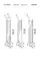
- FIG. 4shows a document image with horizontal primitive white areas extracted
- FIG. 5shows a document image with vertical primitive white areas extracted
- FIG. 6Ashows a document image with major white regions extracted
- FIG. 6Bshows the document elements segmented and extracted
- FIG. 7is a flow chart of one embodiment of the method for extracting major white regions and document elements
- FIG. 8is a flow chart of one embodiment of the method for extracting major white regions
- FIGS. 9A-Bare a flow chart of one embodiment of the method for extracting primitive white areas
- FIGS. 10-13graphically illustrate various ways primitive white areas are formed and primitive white gaps are located when the top of a bounding box is encountered in the scanline;
- FIGS. 14-16graphically illustrate various ways primitive white areas are formed and primitive white gaps are located when the bottom of a bounding box is encountered in the scanline;
- FIGS. 17A-Bare a flow chart of one embodiment of the method for grouping remaining primitive white areas into major white regions
- FIGS. 18-23graphically illustrate various ways primitive white areas are labeled, removed and grouped
- FIG. 24is a flow chart of one embodiment of the method for assigning group labels to primitive white areas
- FIG. 25is a flow chart of one embodiment of the method for examining remaining groups for regrouping
- FIGS. 26A-Bare a flow chart of one embodiment of the method for trimming ends of primitive white areas within groups
- FIGS. 27-29graphically illustrate how ends of groups of primitive white areas are trimmed and merged
- FIG. 30is a flow chart of one embodiment of the method for merging adjacent primitive white areas into a single primitive white area
- FIG. 35is a flow chart of one embodiment of the method for extracting document elements
- FIG. 36is a flow chart of one embodiment of the method for removing major white regions not forming closed loops
- FIG. 37is a flow chart of one embodiment of the method for dividing remaining major white regions into segments
- FIG. 38is a flow chart of one embodiment of the method for generating a list of outermost segments
- FIG. 39is a flow chart of one embodiment of the method for generating current innermost closed loops
- FIG. 40shows a document image segmented into major white regions before major white regions are removed
- FIG. 41shows the document image of FIG. 40 with the major white regions not forming closed loops removed
- FIG. 42shows another document image before the remaining major white regions are divided into segments
- FIG. 43shows the document image of FIG. 42 divided into segments
- FIG. 44shows the segmented document image of FIG. 43 with segments bounded by only one intersection point removed
- FIG. 45shows the document image of FIG. 44 with the list of outermost segments generated
- FIG. 47shows the document image of FIG. 44 after a first closed loop is completed
- FIG. 48shows the document image of FIG. 44 with a second closed loop completed
- FIG. 49shows the document image of FIG. 44 with a third and final closed loop completed.
- FIG. 1shows a first preferred embodiment of a block diagram of a document element segmentation system 100.
- the document element segmentation system 100 describedis only one of many possible embodiments for implementing the document element segmentation method explained below. Therefore, the document element segmentation system 100 set forth is exemplary only and should not be construed to limit the various types and configurations of systems which can be used to implement the document element segmentation method.
- FIG. 1shows a general purpose computer 400 having various means for segmenting a document image.
- the document element segmentation system 100includes a memory 410, a connected component identifying means 420, a bounding box generating means 430, a major white region extraction means 440, a document element extraction means 450 and a processor 460, all connected together by a bus 405.
- a scanner 200 and a printer 300are also connected to the bus 405.
- Document image datais first input into the connected component identifying means 420 by a scanner 200 or from a memory 410.
- the memory 410may be located within the general purpose computer 400 or without in the form of a disk drive, CD-ROM, EPROM, and the like, as well known in the art.
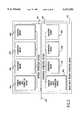
- FIG. 3shows an exemplary document image 600.
- the connected components 610are found within the document image 600.
- Each connected component 610comprises a series of adjacent "on” (i.e., black) pixels surrounded by "off” (i.e., white) pixels.
- Systems for identifying connected components 610 in document images 600are well known in the art.
- the bounding box generating means 430generates a bounding box 620 for each connected component 610.
- the bounding box 620is a minimum-sized rectangular box which completely encloses the corresponding connected component 610, as shown in FIG. 3.
- Systems for generating bounding boxes 620 from connected components 610are also well known in the art.
- the document image data with bounding box informationis sent to the major white region extraction means 440, which extracts major white regions 660 in the vertical and horizontal directions of the document image 600, as shown in FIGS. 4 and 5.
- the major white region extraction means 440is divided into two sections, a vertical extraction section 441 and a horizontal extraction section 442, each connected to the bus 405, as shown in FIG. 2.
- Both the vertical extraction section 441 and the horizontal extraction section 442contain a primitive white area extraction means 443, a comparison means 444, an elimination means 445 and a grouping means 446, each connected to the bus 405, and operate in a similar fashion.
- the horizontal extraction section 442first extracts primitive white areas 630-1 to 630-10 and assembles major white regions 660 in the horizontal direction.
- the vertical extraction section 441first extracts primitive white areas 630-11 to 630-19 and assembles major white regions 660 in the vertical direction.
- horizontal primitive white areas 630 and 630' having a width greater than a width threshold 640 and a height greater than a height threshold 650 and vertical primitive white areas 630 and 630' having a height greater than a height threshold 650' and a width greater than a width threshold 640'are identified as the major white regions 660. It should be appreciated that the height and width thresholds 640, 650, 640' and 650' shown in FIGS. 4 and 5 are not shown to scale.
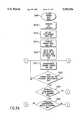
- the document element extraction means 450uses the major white regions 660 to segment the document elements 670 within the document image 600, as shown in FIGS. 6A and 6B.
- the document elements 670are extracted by tracing the major white regions 660 to find closed loops. A closed loop which has no other closed loops inside of it segments a document element 670 from the rest of the document image 600, as shown in FIG. 6B.
- FIG. 6Bthere are three closed loops which do not contain other closed loops. This means that there are three segmented document elements 670 contained in the document image 600. It should be noted that document elements 670 need not be rectangular in shape, and may have more than four sides.
- the segmented document elements 670are output to a variety of system components including the memory 410, a printer 300, and a processor 460. How the segmented document elements 670 are output depends upon what is to be done with the segmented document elements 670.
- the document elements 670may be stored in the memory 410 or printed on a printer 300.
- the segmented document elements 670may be further processed by a processor 460, for example, to perform an optical character recognition process upon the connected components contained within each segmented document element 670.
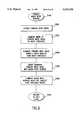
- FIG. 7outlines one preferred embodiment of the method for extracting the major white regions 660 and segmenting the document elements 670.
- step S110the document image 600 is input.
- the input document image 600has a number of document elements 670.
- step S120the connected components 610 of the document image 600 are identified.
- step S130a bounding box 620 is generated for each of the connected components 610 identified in step S120.
- step S140the major white regions 660 are extracted.
- step S150the document elements 670, segmented by the major white regions 660, are extracted. Then, in step S160, the process ends.
- FIG. 8outlines a first preferred embodiment of the major white region extraction process of step S140.
- the primitive white areas 630are extracted. As shown in FIG. 4, the primitive white areas 630 are rectangular-shaped areas of white space between the bounding boxes 620.
- the height and width of each of the horizontal primitive white areas 630is compared to a width threshold 640', a height threshold 650, and the height and width of each vertical primitive white areas 660 is compared to a height threshold 650' and a width threshold 640'.
- the width threshold 640 in the horizontal directionis preferably set to one-third of the length of the document image 600 in the horizontal direction.
- the height threshold 650 in the horizontal directionis set to a value greater than the line spacing of the text in the document image.
- the height threshold 650' in the vertical directionis preferably set to one-third of the length of the document image 600 in the vertical direction.
- the width threshold 640' in the vertical directionis set to a value greater than the line spacing of the text in the document image.
- step S400the horizontal primitive white areas 630 having widths smaller than the width 640 threshold and the vertical white areas 630 having heights smaller than the height threshold 650' are eliminated.
- step S500the remaining primitive white areas 630 are grouped and the major white regions 660 are established.
- step S600those major white regions 660 which have at least one of their vertical or horizontal extents which is less than the corresponding vertical or horizontal threshold are eliminated. Alternately, only those major white regions 660 which have both their vertical and horizontal extents less than the corresponding thresholds are eliminated.
- step S700control returns to step S150.
- step S216the current scanline 1000 is located at the top of the document image 600.
- step S217scanning along the current scanline 1000 is begun from left to right.
- step S2108the scanline 1000 is checked to determine if an edge of a bounding box or the edge of the document image 600 has been encountered. If an edge has been encountered, control continues to step S220. Otherwise, control returns to step S217 for further scanning of the current scanline 1000.
- step S220if the edge encountered is a previously unencountered top of one of the bounding boxes 620, control jumps to step S222.
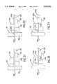
- step S222as shown in FIG. 10, the primitive white gap 680-A in the gap list which touches the top edge of the bounding box 620 is identified. There may be one or more such primitive white gaps 680-A.
- step S223a bottom for each primitive white gap 680-A which touches the top edge of the bounding box 620 is established.
- step S224the primitive white gaps 680-A are removed from the gap list.
- step S226the primitive white gaps 680-A removed from the gap list are placed on the primitive white gap list as primitive white areas 630.
- step S2208the new primitive white gaps 680-B having a top located along the same line as the top edge of the bounding box 620 and a side adjacent to the side of the bounding box 620 are established, as shown in FIG. 11.
- the top edge of the previously unencountered bounding boxmay intersect one or both of the vertical edges of the primitive white gaps 680-A. In this case, there will be none, or only one, new primitive white gap 680-B added to the gap list.
- step S229the new primitive white gaps 680-B are listed on the gap list. Then, control returns to step S217 for further scanning along the current scanline 1000.
- step S217Scanning the current scanline 1000 is continued in step S217. If another previously unencountered top edge of one of the bounding boxes 620 is encountered, steps S222-S229 described above are repeated.
- step S220If, in step S220, the encountered edge is not another previously unencountered top edge of one of the bounding boxes 620, control continues to step S230.
- step S230if the edge encountered is a previously unencountered bottom edge of a bounding box 620, control continues to step S232.
- step S232the primitive white gaps 680-B which touch the sides of the bounding box 620 whose bottom edge has been located are identified. Generally, there will be at least two such gaps 680-B, although there could be fewer or more. Rarely, if one side of the bounding box 620 is flush with an edge of the document image 660 or another bounding box 620, there will only be one gap 680-B.
- step S233a bottom is established for each primitive white gap 680-B touching a side of the bounding box 620.
- those primitive white gaps 680-B having newly established bottom edgesare removed from the gap list.
- the primitive white gaps 680-Bare placed on the primitive white area list as primitive white areas 630.
- new primitive white gaps 680-Chaving a top along the same line as the bottom edge of the newly encountered bounding box 620 and left and/or right sides established at sides of other bounding boxes 620 or at the far left and/or right sides of the document image 600 are established.
- step S239the newly established primitive white gaps 680-C are listed on the gap list. Then, control returns to step S217 for further scanning along the current scanline 1000.
- FIGS. 12-16show a few of the possibilities which may occur when the top or the bottom of the bounding box 620 is encountered in the scanline 1000.
- FIG. 12shows a primitive white gap 680-A touching the top of the bounding box 620 and extending only to the right of the right side of the bounding box 620.
- a bottom for the primitive white gap 680-Ais established at the top of the bounding box 620 and a new primitive white gap 680-B is established to the right of the bounding box 620 having a top along the same line as the top of the bounding box 620.
- FIG. 13shows a primitive white gap 680-A touching the top edge of a bounding box 620, but not extending to either the left or right sides of the bounding box 620.
- a bottom for the primitive white gap 680-Ais established at the top of the bounding box 620 but no new primitive white gaps 680-B are established.
- FIG. 14shows the bottom of a bounding box 620 being encountered in the scanline 1000.
- Primitive white gaps 680-Bare located on either side of the bounding box 620 and touch the sides of the bounding box 620. Therefore, bottoms are established for the primitive white gaps 680-B on either side of the bounding box 620 and the primitive white gaps 680-B having newly established bottoms are removed from the gap list and listed on the primitive white area list as primitive white areas.
- a new primitive white gap 680-Cis established below the bounding box 620 bottom, having a top located along the same line as the bottom of the bounding box 620. This new primitive white gap 680-C is listed on the gap list.
- FIG. 15shows a bottom of a bounding box 620 being encountered in the scanline 1000, with a primitive white gap 680-B located to the right of the bounding box 620.
- a bottom for the primitive white gap 680-B located on the right of the bounding box 620is established along the same line as the bottom of the bounding box 620, establishing a new primitive white area.
- a new primitive white gap 680-C having a top along the same line as the bottom of the bounding box 620, a left side located along the right side of a second bounding box 620 and a right side located along the far right edge of the document image 600is established.
- FIG. 16shows the scanline 1000 encountering a bottom of a bounding box 620, with no primitive white gaps 680-B touching the sides of the bounding box 620.
- a new primitive white gap 680-Cis established having a top at the bottom of the bounding box 620, a left side located along the right side of a second bounding box 620 and a right side located along the left side of a third bounding box 620.
- step S240the next scanline down the document image becomes the current scanline 1000.
- step S242the current scanline 1000 is checked to see if it coincides with the last scanline of the document image. If so, control continues to step S244, where bottoms for all of the primitive white gaps 680A, 680B, and 680-C remaining on the gap list are established at the bottom of the document image 600.
- step S246new primitive white areas 630 are listed on the primitive white area list corresponding to the primitive white gaps 680 having bottoms at the bottom of the document image 600. Then, in step S248, control returns to step S300.
- FIGS. 17A-Boutline one preferred embodiment for the process for grouping the primitive white areas into major white areas of step S500.
- each of the primitive white areas 630which remain after eliminating the too-small primitive white areas in step S400, is examined.
- FIG. 18shows a number of primitive white areas 630A to 630N remaining after all of the too-small primitive white areas are removed.
- group labelsare appended to each group of one or more of the primitive white areas 630A-630N.
- the primitive white areas 630A-630Nare grouped so that primitive white areas which uniquely touch each other are in the same group.
- the primitive white areas 630A-630Nare grouped into six distinct groups 40-46.
- step S514after the group labels are assigned to the primitive white areas 630A-630N, groups of primitive white areas 630 having the same group label are gathered into a single group 41-46, as shown in FIG. 19.
- step S516for horizontal groups, the height 650 of each horizonal group 40-46 is compared to the height threshold 650.
- the height 47 of a groupis the size of the group in a direction perpendicular to the direction of each primitive white area's 630 width, as shown in FIG. 21.
- the "height" 47 of a groupis the size of the group in the horizontal direction and the height 47 of the vertical group is compared to the width threshold 640'
- the height threshold 650 or 640'is set to a value greater than the line spacing of the text in the document image 600.
- step S5108a group which has a height 47 smaller than the height threshold 650 or 640' and touches no other group, is removed. This is the case with group 40 of FIG. 19.
- step S520branched groups which have a height 650 or 640' smaller than the height threshold 47 and touch other groups only on one surface (i.e., only on either the bottom of the group or the top of the group) are removed. This is the case for group 45 of FIG. 20.
- step S522after removing isolated and branched groups which are smaller than the height threshold 650 or 640', the remaining groups 41-44 and 46 are examined to determine if the number of remaining groups can be reduced by combining two or more of the groups 41-44 and 46.
- step S524the ends of primitive white areas which have a height smaller than the height threshold are trimmed off. This is shown in FIGS. 27-29 and described in greater detail below.
- step S526the primitive white areas 630 within a group which touch and have common left and right edges are merged into a single primitive white area 630.
- primitive white areas 630O and 630P, and 630Q, 630R, 630S and 630Teach have common left and right edges.
- the seven primitive white areas in the three groupsare merged into three primitive white areas 630O,630Q and 630U as shown in FIG. 23.
- step S528the removed primitive white areas 630 whose heights 47 are smaller than the height threshold 650 are then reexamined to determine if some of these reexamined primitive white areas 630 can be, in step S530, merged back into one of the remaining primitive white areas 630.
- step S532the height 47 of each remaining primitive white area 630 is compared to the height threshold 650 or 640'.
- primitive white areas 630 which have a height 47 greater than the height threshold 650 or 640'are determined to be major white regions 660.
- FIG. 24outlines one preferred embodiment of the process of assigning labels to the primitive white areas 630 of step S512.
- the primitive white area 630-A of FIG. 18 located at the top of the document imageis selected as the current white area.
- the primitive white area currently being examinedis called the current primitive white area.
- the current primitive white areais checked to determine if a label has already been assigned to it. If so, control jumps to step S5127. If not, control continues to step S5123.
- step S5123the number of other primitive white areas touching the top of the current primitive white area is determined. Of course, for the topmost primitive white area 630A, this will be zero. For other ones of the primitive white areas 630, there may be zero, one or more than one other primitive white area 630 touching it.
- step S5124the number of other primitive white areas 630 touching the top of the current primitive white area determined in step S5123 is checked to see if it is exactly equal to one. If so, control continues to step S5125 where the label assigned to the single other primitive white areas 630 touching the top of the current primitive white area is assigned as well to the current primitive white area.
- step S5126a new label is assigned to the current primitive white area. This is, of course, the situation for the topmost primitive white area 630-A. Then, both steps S5125 and 5126 continue to step S5127.
- step S5127the number of other primitive white areas 630 touching the bottom of the current primitive white area is determined. Then, in step S5128, the number touching the bottom of the current primitive white area is checked to determine if it is less than or equal to one. If so, control jumps to step S5130. If not, control continues to step S5129, where each one of the other primitive white areas 630 touching the bottom of the current primitive white area are assigned new and different labels.
- FIG. 25outlines one preferred embodiment for the method of grouping the primitive white area groups of step S522.
- step S5221the uppermost and leftmost unexamined white area group is selected as the current primitive white area group.
- step S5222the number of other primitive white area groups touching the bottom of the current primitive white area group is determined.
- step S5223if the number of other primitive white area groups touching the bottom of the current primitive white area group is not one, control jumps to step S5227. Otherwise, if the number is equal to one, control continues to step S5224.
- step S5224the total number of groups touching the top of the single groups touching the bottom of the current group is determined.
- step S5225if the total number of touching groups is exactly equal to one, control continues to step S5226. Otherwise, control again jumps to step S5227.
- step S5226the label assigned to the single primitive white area group touching the bottom of the current primitive white area group is replaced with the label assigned to the current primitive white area group, thus merging the two groups. Control then returns to step S5222.
- step S5227the document image 600 is checked to determine if any unexamined primitive white area groups remain in the document image 600. If so, control continues to step S5228, where the next group is selected as the current group. Then, control jumps back to step S5222. Otherwise, control jumps to step S5229, which returns control to step S524.
- FIGS. 26A-Boutline one preferred embodiment of the procedure for trimming the ends of the primitive white areas within a group of step S5241.
- a first one of the primitive white area groupsis selected as the current primitive white area group.
- the leftmost side of the current primitive white area groupis identified as the current leftmost side and the primitive white area of the current primitive white area group having the leftmost side is identified as the current area or current subgroup.
- step S5243the height 47 of the current leftmost side of the current primitive white area or current subgroup of the current groups of primitive white areas is compared against the height threshold 650 or 640' if the height threshold 650 or 640' is not exceeded, control continues to step S5244, where the current group is checked to see if there are any remaining primitive white areas which touch the current area or subgroup.
- step S5245the next leftmost side of the current primitive white area which touches the current area or current subgroup is identified as the current leftmost side. This primitive white area is added to the current area to form the current subgroup or to the current subgroup. Control then returns to step S5243. This loop remains in place until the height threshold 650 or 640' is exceeded by the height 47 of the current area or subgroup or no more touching primitive white areas remain. Control then continues to step S5246.
- step S5246the ends of the primitive white areas within the current primitive white area group which extend to the left of the current leftmost side of the current primitive white area or subgroup are removed. Control then continues to step S5247, which determines if there are any other primitive white areas of the current group whose left ends have not yet been trimmed and are not greater than the height threshold. If there are other areas whose left ends need trimming, control jumps back from step S5247 to step S5242.
- step S5248identifies the rightmost side of the primitive white area of the current primitive white area group as the current rightmost side.
- step S5249the height 47 of the current rightmost side is compared against the height threshold 650 or 640'. If the height threshold 650 or 640' is not exceeded, control continues to step S5250, where the current group is checked to see if there are any remaining primitive white areas which touch the current area or subgroup.
- step S5251If any touching primitive white areas remain, control continues to step S5251. Otherwise, if no touching primitive white areas remain, control jumps to step S5252. In step S5251, the next rightmost side of the primitive white area which touches the current white area or subgroup of the current primitive white area group is identified as the current rightmost side. Control then returns to step S5249. This loop continues until the height threshold is exceeded or no more touching primitive white areas remain. Then, control continues to step S5252, where the ends of the primitive white areas of the current primitive white area or subgroup which extend to the right of the current rightmost side are removed.
- step S5253determines if there are any other primitive white areas of the current group whose right ends have not yet been trimmed and are not greater than the height threshold. If there are other areas whose right ends need trimming, control jumps back to step S5248. Otherwise, if there are no other areas needing trimming, control continues to step S5254, which determines if there are any untrimmed primitive white area groups remaining within the document image 600. If there are, control continues to step S5255, where a next primitive white area group is selected as the current primitive white area group. Control then returns to step S5242. Otherwise, if all of the primitive white area groups of the document image 600 have been trimmed, control continues to step S5256, which returns control to step S526.
- FIGS. 27-29graphically show the operation of the trimming process outlined in FIGS. 26A-26B.
- a group 48comprises individual primitive white areas 631-637.
- primitive white area 635 and 636define the left-most edge of the group 48.
- the vertical height 47 of the common left edge of the primitive white areas 635 and 636is compared to the height threshold 650.
- the height threshold 650when measured from the bottommost edge of the primitive white area 636, extends beyond the top edge of the primitive white area 634 but below the top edge of the primitive white area 633.
- primitive white areas 635 and 636are grouped together as the current subgroup and the primitive white areas touching this current subgroup are identified. In FIG. 27, this includes primitive white areas 634 and 637.
- the left edge of the primitive white areas 635 and 636is trimmed back to the left edge of the primitive white area 634, as shown in FIG. 28. That is, the current group is trimmed back to the leftmost edge of those primitive white areas touching the current group. The height of this new left edge is then compared to the height threshold 650. Since the height threshold 650 is still not exceeded, primitive white area 634 is added to the current group, and the primitive white areas touching this new current group are identified. The left edge of the primitive white areas 634-636 is further trimmed back to the left edge of the primitive white area 633. Similarly, the left-edge of the primitive white area 631 is also trimmed back to the left edge of the primitive white area 632. The left edge of the current area or group is always adjusted or trimmed to the next leftmost edge of the primitive white areas which touch the current area or group.
- the primitive white area 632touches the primitive white area 631 but the other primitive white areas 633-637 do not. While the height 47 of the primitive white area 631 does not figure into the comparison against the height threshold 650, primitive white area is also trimmed back so that the leftmost point of the group 48 does not extend any further left than the leftmost edge of the trimmed subgroup of primitive white regions which do exceed the height threshold 650. Since, as shown in FIG. 29, the leftmost edge of the group 48 defined by the primitive white areas 633-636 exceeds the height threshold 650, the trimming process for the leftmost edge of the group 48 is finished.
- the rightmost edge of the group 48defined by the rightmost edge of the primitive white area 636 and 637 would first be trimmed back to be collinear with the rightmost edges of the primitive white areas 631 and 632. Since these primitive white areas are not adjacent, and neither alone exceeds the height threshold 650, the rightmost edges of the primitive white areas 631,632, 636, and 637 is further trimmed back to the rightmost edge of the primitive white areas 633 and 634. Since the rightmost edge defined by the primitive white areas 631-634 now exceeds the height threshold 47, the trimming process is complete.
- FIG. 30outlines one preferred embodiment of the process for merging two or more primitive white areas 630 into a single primitive white area 630 of step S530.
- a first primitive white area 630is selected as the current primitive white area.
- the current white areais checked against the vertical threshold to determine if its vertical height is less than or more than the vertical threshold. If the vertical height of the current area is more than the vertical threshold, control jumps from step S5302 to S5311. Otherwise, if the vertical height of the current white area is less than the vertical threshold, control continues to step S5303.
- step S5303a list of other primitive white areas which touch the current primitive white area is generated.
- step 5304the list of touching area is checked to determine if two of the touching area touch the same portion of the current white area. For example, as shown in FIG. 31, the touching primitive areas 631 and 633 touch the same portion of the current white area 632. Likewise, the touching primitive white areas 634 and 635 also touch the same portion of the current white area 632. If there are no pairs of touching areas on the list which touch the same portion of the current white area, control jumps to step S5308. Otherwise, if there are two touching area which touch the same portion of the current white area, control continues to step S5305.
- step S5305the edges of the pair of touching areas are checked to determine if they sufficiently align. For example, as shown in FIG. 31, the edges of the touching white areas 631 and 633 are sufficiently aligned, while the edges of the touching areas 634 and 635 are not sufficiently aligned.
- step S5304one pair of two touching area is selected and in step S5305 the selected pair is checked. If, in step S5305, the edges are not sufficiently aligned, control jumps back to step S5304 which checks another one of the pairs of touching areas. This loop, through step S5305 and back to step S5304, will continue until each touching pair is checked.
- step S5305If, in step S5305, the edges of the pair of touching areas are sufficiently aligned, control continues to step S5306, where the pair of touching areas are removed from the list of touching areas and the current white area is divided into three parts, as shown in FIG. 32.
- the current white areawill only be divided into two portions.
- step S5307the two touching areas and the touched portion of the current white area are merged into a single white area. This process is shown in FIGS. 32 and 33, where the touching white areas 632 and 633 and the touched portion 632c of the current white area 632 are merged into a single white area 631. Then, control returns to step S5304 to check another one of the pairs of touching areas.
- step S5308the list of touching areas is checked to determine if any areas remain on the list. If no touching areas remain on the list, control jumps from step S5308 to step S5311. Otherwise, if areas do remain on the list of touching areas, control continues to step S5309.
- step S5309the widest touching area which remains on the list of touching areas is selected, and the part of the current white area which is touched by the selected widest area is further divided into three portions.
- the widest remaining portion 634touches portion 632b of the current white area 632. Accordingly, the portion 632b is further divided into an untouched portion 632d and a touched portion 632e. As shown in FIG. 34, the touched portion 632e is merged into the widest area 634.
- a current white area 632is touched by six other primitive white areas 631 and 633-637.
- the primitive white areas 631 and 634would have been previously compared against the vertical threshold, and if they are less than it, would have been previously analyzed. In this case, neither one of the touching primitive areas 631 or 634 is less then the vertical threshold.
- those touching primitive white areas which touch a common portion of the current primitive white area 632 and have edges which are sufficiently alignedare merged into a single white area.
- the touching primitive white areas 631 and 633are merged together, along with the commonly touched portion 632c of the current portion 632.
- the widest remaining touching area on the list of touching areasis selected and the touched portion 632e of the current white portion 632 is merged into the selected widest remaining touching white area 634.
- any other touching area on the list of touching areas which also touches the touched area 632eis removed from the list of touching areas. This process of locating the widest remaining touching area continues until no touching primitive white areas remain in the list of primitive white areas.
- the touched portions of the current area 632are merged into the touching white areas 636 and 637 and the current white area is further divided into untouched portions 632d, 632f and 632g.
- FIG. 35outlines one preferred embodiment of the method for extracting document elements of step S150.
- the major white regions 660 not forming closed loopsare removed.
- the remaining major white regions 660are divided into segments.
- the outermost segmentsi.e., those segments closest to the boundaries of the document image 600, are tracked in a first direction and the corresponding direction field of each tracked segment is marked.
- the first uppermost horizontal segment from the list of segmentsis selected as the first and the current segment.
- step S1100a current closed loop which includes the first segment is generated by moving in the direction opposite to the first direction and the direction field of each segment corresponding to this direction is marked. Then, in step S1200, those segments which have both direction fields marked are removed. In step S1300 the current document element 670 defined by the current closed loop is output. Then, in step S1400, the list of segments is checked to determined if any segments remain on the list. If so, control continues to step S1500, where the uppermost horizontal segment remaining on the list is selected from the list of segments. Control then returns to step S1100. If no segments remain on the list of segments, control continues from step S1400 to step S1600, which returns control to step S160.
- FIG. 36outlines one preferred embodiment of the process for removing major white regions not forming closed loops of step S700.
- step S710any major white regions 660 not touching at least two other major white regions 660 are located. This is graphically shown in FIG. 40, where the major white regions 666 and 667 of the major white regions 661-667 forming the document image 600 each touch only one other major white region. Accordingly, those regions are removed in step S720.
- step S730the document image 600 is again checked to determine if there are any remaining regions which fail to touch at least two other regions. As shown in FIG. 40, the major white region 665 initially touched two other major white regions 661 and 667. However, because major white regions 667 was previously removed, the major white region 665 now touches only one other major white region.
- the major white region 661is divided into four segments 661a-661d.
- the major white region 662has three intersection points, where it is crossed by major white regions 661,666 and 663. Accordingly, the major white region 662 is divided into segments 662a-d.
- the major white regions 663-667are divided into segments 663a-663c, 664a-664d, 665a-665c, 666a-666c, and 667a-667c.
- step S840those segments of the document image 600 which are bounded by only a single intersection point are removed, as shown in FIG. 44.
- the segments 661a, 661d, 662a, 662d, 663a, 663c, 664a, 664d, 665a, 665d, 666a, 666c, 667a, and 667care removed from the document image 600, as they each have one end which is not bounded by an intersection point. Accordingly, this leaves segments 661b-c, 662b-c, 663b, 664b-c, 665b-c, 666b and 667b remaining on the document image 660.
- step S850after the current major white region has been segmented and its unbounded segments removed, the document image 600 is checked to determine if any major white regions which have not yet been divided remain. If so, control flows to step S860 where the next undivided major white region is selected as the current region. Control then jumps back to step S820. If no major undivided white regions remain in the document image 600, control jumps from Step S850, to step S870, which returns control to step S900.
- FIG. 38shows one preferred embodiment of the method for generating lists of outermost segments of step S900.
- Each segmenthas two fields associated with it for representing that the segment has been tracked in each direction (left to right and right to left for horizontal segments, and top to bottom and bottom to top for vertical segments)
- step S910the uppermost and leftmost horizontal segment is selected as the first segment and as the current segment. It should be appreciated that selecting a horizontal support is not required, and that a vertical segment can be selected instead.
- the field representing the direction, left to right, in the selected segmentis marked. For the document image 600 shown in FIG. 45, this would be the segment 662b.
- step S960the next segment is checked to see if it is the first segment. If not, control continues to step S970, where the next intersection point is selected as the last intersection point and the next segment is selected as the current segment. Control then returns to step S930. This process then tracks segments 661c, 664b, 664c, 663b and 662c. The fields corresponding the tracked directions in each segment are marked.
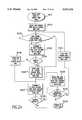
- FIG. 39shows one preferred embodiment of the method for generating the current innermost closed loop of step S1100.
- step S1110the uppermost horizontal segment of the list of segments is selected as a first loop segment and as a current loop segment and the left intersection point of the current outermost segment is selected as the last intersection point.
- step S1120the current loop segment is scanned by tracking clockwise from the last intersection point until the next intersection point of the current loop segment is encountered.
- step S1130a next segment is selected by searching counterclockwise about the next intersection point until a segment is found, starting from the opposite direction of the tracking. As shown in FIG. 46, the line formed in step S1130 is rotated counterclockwise along the line B about the right-hand intersection point of the segment 662b.
- step S1140the next loop segment is checked to see if it is the first loop segment, If not, control continues to step S1150, where the next loop segment is selected as a current loop segment and the next intersection point is selected as the last intersection point.
- This processis shown in FIG. 47 where the segment 662b, 666b, 665c, 665b, and 661b form an interloop enclosing the first document element 671. The fields corresponding to the tracked directions in each segment are marked.
- step S1140If, in step S1140, the next segment is the first segment, control jumps to step S1160 where the current closed loop is treated as completed and the interior of the current closed loop is identified as the next document element. Control then continues to step S1170, which returns control to step S1200.
- FIGS. 48 and 49show the process for identifying the second and third document element 672 and 673.
- the segments 661b and 662bare removed, as described above with respect to step S1200, because in finding the outermost loop, both fields of each of these segments have been marked. It should also be appreciated that if the closed loop is traced out in the counterclockwise direction, the line from the next intersection point would be rotated clockwise.
Landscapes
- Engineering & Computer Science (AREA)
- Computer Vision & Pattern Recognition (AREA)
- Physics & Mathematics (AREA)
- Artificial Intelligence (AREA)
- General Physics & Mathematics (AREA)
- Multimedia (AREA)
- Theoretical Computer Science (AREA)
- Computer Graphics (AREA)
- Geometry (AREA)
- Character Input (AREA)
Abstract
Description
Claims (18)
Priority Applications (4)
| Application Number | Priority Date | Filing Date | Title |
|---|---|---|---|
| US08/315,875US5555556A (en) | 1994-09-30 | 1994-09-30 | Method and apparatus for document segmentation by background analysis |
| US08/483,765US5757963A (en) | 1994-09-30 | 1995-06-07 | Method and apparatus for complex column segmentation by major white region pattern matching |
| US08/473,909US5699453A (en) | 1994-09-30 | 1995-06-07 | Method and apparatus for logically tagging of document elements in the column by major white region pattern matching |
| JP24321395AJP3832879B2 (en) | 1994-09-30 | 1995-09-21 | Document image segmentation device |
Applications Claiming Priority (1)
| Application Number | Priority Date | Filing Date | Title |
|---|---|---|---|
| US08/315,875US5555556A (en) | 1994-09-30 | 1994-09-30 | Method and apparatus for document segmentation by background analysis |
Related Child Applications (2)
| Application Number | Title | Priority Date | Filing Date |
|---|---|---|---|
| US08/473,909Continuation-In-PartUS5699453A (en) | 1994-09-30 | 1995-06-07 | Method and apparatus for logically tagging of document elements in the column by major white region pattern matching |
| US08/483,765Continuation-In-PartUS5757963A (en) | 1994-09-30 | 1995-06-07 | Method and apparatus for complex column segmentation by major white region pattern matching |
Publications (1)
| Publication Number | Publication Date |
|---|---|
| US5555556Atrue US5555556A (en) | 1996-09-10 |
Family
ID=23226440
Family Applications (1)
| Application Number | Title | Priority Date | Filing Date |
|---|---|---|---|
| US08/315,875Expired - LifetimeUS5555556A (en) | 1994-09-30 | 1994-09-30 | Method and apparatus for document segmentation by background analysis |
Country Status (2)
| Country | Link |
|---|---|
| US (1) | US5555556A (en) |
| JP (1) | JP3832879B2 (en) |
Cited By (75)
| Publication number | Priority date | Publication date | Assignee | Title |
|---|---|---|---|---|
| US5696843A (en)* | 1994-06-22 | 1997-12-09 | Sharp Kabushiki Kaisha | Automatic image quality controlling apparatus for use in an electronic copier |
| US5774579A (en)* | 1995-08-11 | 1998-06-30 | Canon Kabushiki Kaisha | Block selection system in which overlapping blocks are decomposed |
| US5835629A (en)* | 1995-04-13 | 1998-11-10 | Olympus Optical Co., Ltd. | Code pattern-image processing apparatus |
| US5956468A (en)* | 1996-07-12 | 1999-09-21 | Seiko Epson Corporation | Document segmentation system |
| EP0880272A3 (en)* | 1997-05-22 | 2000-02-23 | Samsung Electronics Co., Ltd. | Method of recognizing printing region |
| US6038351A (en)* | 1997-10-28 | 2000-03-14 | Cash Management Solutions | Apparatus and method for multi-entity, mixed document environment document identification and processing |
| US20020168090A1 (en)* | 2001-03-30 | 2002-11-14 | Bruce Ben F. | Method and system for image processing |
| US6507670B1 (en)* | 1998-03-05 | 2003-01-14 | Ncr Corporation | System and process for removing a background pattern from a binary image |
| US20030123730A1 (en)* | 2001-12-29 | 2003-07-03 | Kim Doo Sik | Document recognition system and method using vertical line adjacency graphs |
| US20030163785A1 (en)* | 2002-02-28 | 2003-08-28 | Hui Chao | Composing unique document layout for document differentiation |
| US20030190094A1 (en)* | 2001-11-29 | 2003-10-09 | Kazuaki Yokota | Document identification device, document definition method and document identification method |
| WO2003069554A3 (en)* | 2002-02-13 | 2003-12-24 | Convey Corp | Method and system for interactive ground-truthing of document images |
| US20040037473A1 (en)* | 2002-08-20 | 2004-02-26 | Ahmed Mohamed N. | Systems and methods for content-based document image enhancement |
| US6701008B1 (en)* | 1999-01-19 | 2004-03-02 | Ricoh Company, Ltd. | Method, computer readable medium and apparatus for extracting characters from color image data |
| US20040096102A1 (en)* | 2002-11-18 | 2004-05-20 | Xerox Corporation | Methodology for scanned color document segmentation |
| US20040148577A1 (en)* | 2003-01-27 | 2004-07-29 | Ying-Qing Xu | Learning-based system and process for synthesizing cursive handwriting |
| US6879704B2 (en)* | 1998-07-10 | 2005-04-12 | Fujitsu Limited | Image processing apparatus, image processing method and recording medium |
| US20050163374A1 (en)* | 2004-01-28 | 2005-07-28 | Ferman A. M. | Methods and systems for automatic detection of continuous-tone regions in document images |
| US20060262962A1 (en)* | 2004-10-01 | 2006-11-23 | Hull Jonathan J | Method And System For Position-Based Image Matching In A Mixed Media Environment |
| US20070036435A1 (en)* | 2005-08-12 | 2007-02-15 | Bhattacharjya Anoop K | Label aided copy enhancement |
| US20070047816A1 (en)* | 2005-08-23 | 2007-03-01 | Jamey Graham | User Interface for Mixed Media Reality |
| US20070140577A1 (en)* | 2005-12-21 | 2007-06-21 | Lexmark International, Inc. | Background intensity correction of a scan of a document |
| US20070189615A1 (en)* | 2005-08-12 | 2007-08-16 | Che-Bin Liu | Systems and Methods for Generating Background and Foreground Images for Document Compression |
| US20070217701A1 (en)* | 2005-08-12 | 2007-09-20 | Che-Bin Liu | Systems and Methods to Convert Images into High-Quality Compressed Documents |
| US20080298718A1 (en)* | 2007-05-31 | 2008-12-04 | Che-Bin Liu | Image Stitching |
| US20090003700A1 (en)* | 2007-06-27 | 2009-01-01 | Jing Xiao | Precise Identification of Text Pixels from Scanned Document Images |
| US20090016615A1 (en)* | 2007-07-11 | 2009-01-15 | Ricoh Co., Ltd. | Invisible Junction Feature Recognition For Document Security or Annotation |
| US20090018990A1 (en)* | 2007-07-12 | 2009-01-15 | Jorge Moraleda | Retrieving Electronic Documents by Converting Them to Synthetic Text |
| US20100174980A1 (en)* | 2009-01-02 | 2010-07-08 | Philip Andrew Mansfield | Identification of Regions of a Document |
| US20100245917A1 (en)* | 2009-03-30 | 2010-09-30 | Nguyen Uoc H | Methods and Systems for Rendering Data |
| US20100245889A1 (en)* | 2009-03-30 | 2010-09-30 | Nguyen Uoc H | Methods and Systems for Rendering Data |
| US20100245887A1 (en)* | 2009-03-30 | 2010-09-30 | Nguyen Uoc H | Methods and Systems for Rendering Data |
| US20100245918A1 (en)* | 2009-03-30 | 2010-09-30 | Nguyen Uoc H | Methods and Systems for Rendering Data |
| US20100245858A1 (en)* | 2009-03-30 | 2010-09-30 | Nguyen Uoc H | Methods and Systems for Rendering Data |
| US20100245888A1 (en)* | 2009-03-30 | 2010-09-30 | Nguyen Uoc H | Methods and Systems for Rendering Data |
| US20100245920A1 (en)* | 2009-03-30 | 2010-09-30 | Nguyen Uoc H | Methods and Systems for Rendering Data |
| US8156115B1 (en) | 2007-07-11 | 2012-04-10 | Ricoh Co. Ltd. | Document-based networking with mixed media reality |
| US8184155B2 (en) | 2007-07-11 | 2012-05-22 | Ricoh Co. Ltd. | Recognition and tracking using invisible junctions |
| US8195659B2 (en) | 2005-08-23 | 2012-06-05 | Ricoh Co. Ltd. | Integration and use of mixed media documents |
| US8201076B2 (en) | 2006-07-31 | 2012-06-12 | Ricoh Co., Ltd. | Capturing symbolic information from documents upon printing |
| US8238609B2 (en) | 2007-01-18 | 2012-08-07 | Ricoh Co., Ltd. | Synthetic image and video generation from ground truth data |
| US8276088B2 (en) | 2007-07-11 | 2012-09-25 | Ricoh Co., Ltd. | User interface for three-dimensional navigation |
| US8335789B2 (en) | 2004-10-01 | 2012-12-18 | Ricoh Co., Ltd. | Method and system for document fingerprint matching in a mixed media environment |
| US20130011052A1 (en)* | 2008-05-09 | 2013-01-10 | United States Postal Service | Methods and systems for analyzing the quality of digital signature confirmation images |
| US8369655B2 (en) | 2006-07-31 | 2013-02-05 | Ricoh Co., Ltd. | Mixed media reality recognition using multiple specialized indexes |
| US8380753B2 (en) | 2011-01-18 | 2013-02-19 | Apple Inc. | Reconstruction of lists in a document |
| US8385660B2 (en) | 2009-06-24 | 2013-02-26 | Ricoh Co., Ltd. | Mixed media reality indexing and retrieval for repeated content |
| US8385589B2 (en) | 2008-05-15 | 2013-02-26 | Berna Erol | Web-based content detection in images, extraction and recognition |
| US8452780B2 (en) | 2006-01-06 | 2013-05-28 | Ricoh Co., Ltd. | Dynamic presentation of targeted information in a mixed media reality recognition system |
| US20130176596A1 (en)* | 2012-01-06 | 2013-07-11 | Fuji Xerox Co., Ltd. | Image processing apparatus, image processing method, and non-transitory computer readable medium |
| US8489987B2 (en) | 2006-07-31 | 2013-07-16 | Ricoh Co., Ltd. | Monitoring and analyzing creation and usage of visual content using image and hotspot interaction |
| US8510283B2 (en) | 2006-07-31 | 2013-08-13 | Ricoh Co., Ltd. | Automatic adaption of an image recognition system to image capture devices |
| US8521737B2 (en) | 2004-10-01 | 2013-08-27 | Ricoh Co., Ltd. | Method and system for multi-tier image matching in a mixed media environment |
| US8543911B2 (en) | 2011-01-18 | 2013-09-24 | Apple Inc. | Ordering document content based on reading flow |
| US20130298301A1 (en)* | 2011-08-31 | 2013-11-14 | Lawrence Theodore Petrakis | Fitness and Training Garment |
| US8600989B2 (en) | 2004-10-01 | 2013-12-03 | Ricoh Co., Ltd. | Method and system for image matching in a mixed media environment |
| US8676810B2 (en) | 2006-07-31 | 2014-03-18 | Ricoh Co., Ltd. | Multiple index mixed media reality recognition using unequal priority indexes |
| US8825682B2 (en) | 2006-07-31 | 2014-09-02 | Ricoh Co., Ltd. | Architecture for mixed media reality retrieval of locations and registration of images |
| US8831361B2 (en) | 2012-03-09 | 2014-09-09 | Ancora Software Inc. | Method and system for commercial document image classification |
| US8838591B2 (en) | 2005-08-23 | 2014-09-16 | Ricoh Co., Ltd. | Embedding hot spots in electronic documents |
| US8856108B2 (en) | 2006-07-31 | 2014-10-07 | Ricoh Co., Ltd. | Combining results of image retrieval processes |
| US8868555B2 (en) | 2006-07-31 | 2014-10-21 | Ricoh Co., Ltd. | Computation of a recongnizability score (quality predictor) for image retrieval |
| US8949287B2 (en) | 2005-08-23 | 2015-02-03 | Ricoh Co., Ltd. | Embedding hot spots in imaged documents |
| US9020966B2 (en) | 2006-07-31 | 2015-04-28 | Ricoh Co., Ltd. | Client device for interacting with a mixed media reality recognition system |
| US9058331B2 (en) | 2011-07-27 | 2015-06-16 | Ricoh Co., Ltd. | Generating a conversation in a social network based on visual search results |
| US9063952B2 (en) | 2006-07-31 | 2015-06-23 | Ricoh Co., Ltd. | Mixed media reality recognition with image tracking |
| US9063953B2 (en) | 2004-10-01 | 2015-06-23 | Ricoh Co., Ltd. | System and methods for creation and use of a mixed media environment |
| US9171202B2 (en) | 2005-08-23 | 2015-10-27 | Ricoh Co., Ltd. | Data organization and access for mixed media document system |
| US9176984B2 (en) | 2006-07-31 | 2015-11-03 | Ricoh Co., Ltd | Mixed media reality retrieval of differentially-weighted links |
| US9384619B2 (en) | 2006-07-31 | 2016-07-05 | Ricoh Co., Ltd. | Searching media content for objects specified using identifiers |
| US9405751B2 (en) | 2005-08-23 | 2016-08-02 | Ricoh Co., Ltd. | Database for mixed media document system |
| US9445108B1 (en) | 2015-05-26 | 2016-09-13 | International Business Machines Corporation | Document compression with neighborhood biased pixel labeling |
| US9530050B1 (en) | 2007-07-11 | 2016-12-27 | Ricoh Co., Ltd. | Document annotation sharing |
| US11117012B2 (en) | 2017-01-06 | 2021-09-14 | Lawrence T. Petrakis | Breathable heavyweight garments for physical conditioning |
| US12045953B2 (en) | 2021-03-27 | 2024-07-23 | Tata Consultancy Services Limited | Extracting region of interest from scanned images and determining an associated image type thereof |
Citations (12)
| Publication number | Priority date | Publication date | Assignee | Title |
|---|---|---|---|---|
| US4698779A (en)* | 1984-05-05 | 1987-10-06 | International Business Machines Corporation | Graphic display with determination of coincidence of subject and clip areas |
| US4876728A (en)* | 1985-06-04 | 1989-10-24 | Adept Technology, Inc. | Vision system for distinguishing touching parts |
| US4887302A (en)* | 1986-07-02 | 1989-12-12 | Kabushiki Kaisha Toshiba | Labelling circuit for image processor |
| US4903311A (en)* | 1987-05-01 | 1990-02-20 | Ricoh Company, Ltd. | Character region extracting method and apparatus capable of implementing the method |
| US4907285A (en)* | 1984-08-24 | 1990-03-06 | Hitachi, Ltd. | Image understanding system |
| US5046114A (en)* | 1985-10-01 | 1991-09-03 | The Palantir Corporation | Method and structure for separating joined patterns for use in pattern and character recognition system |
| US5185813A (en)* | 1988-01-19 | 1993-02-09 | Kabushiki Kaisha Toshiba | Document image processing apparatus |
| US5201011A (en)* | 1991-11-19 | 1993-04-06 | Xerox Corporation | Method and apparatus for image hand markup detection using morphological techniques |
| US5272764A (en)* | 1989-12-08 | 1993-12-21 | Xerox Corporation | Detection of highlighted regions |
| US5335298A (en)* | 1991-08-19 | 1994-08-02 | The United States Of America As Represented By The Secretary Of The Army | Automated extraction of airport runway patterns from radar imagery |
| US5425110A (en)* | 1993-04-19 | 1995-06-13 | Xerox Corporation | Method and apparatus for automatic language determination of Asian language documents |
| US5430808A (en)* | 1990-06-15 | 1995-07-04 | At&T Corp. | Image segmenting apparatus and methods |
- 1994
- 1994-09-30USUS08/315,875patent/US5555556A/ennot_activeExpired - Lifetime
- 1995
- 1995-09-21JPJP24321395Apatent/JP3832879B2/ennot_activeExpired - Fee Related
Patent Citations (12)
| Publication number | Priority date | Publication date | Assignee | Title |
|---|---|---|---|---|
| US4698779A (en)* | 1984-05-05 | 1987-10-06 | International Business Machines Corporation | Graphic display with determination of coincidence of subject and clip areas |
| US4907285A (en)* | 1984-08-24 | 1990-03-06 | Hitachi, Ltd. | Image understanding system |
| US4876728A (en)* | 1985-06-04 | 1989-10-24 | Adept Technology, Inc. | Vision system for distinguishing touching parts |
| US5046114A (en)* | 1985-10-01 | 1991-09-03 | The Palantir Corporation | Method and structure for separating joined patterns for use in pattern and character recognition system |
| US4887302A (en)* | 1986-07-02 | 1989-12-12 | Kabushiki Kaisha Toshiba | Labelling circuit for image processor |
| US4903311A (en)* | 1987-05-01 | 1990-02-20 | Ricoh Company, Ltd. | Character region extracting method and apparatus capable of implementing the method |
| US5185813A (en)* | 1988-01-19 | 1993-02-09 | Kabushiki Kaisha Toshiba | Document image processing apparatus |
| US5272764A (en)* | 1989-12-08 | 1993-12-21 | Xerox Corporation | Detection of highlighted regions |
| US5430808A (en)* | 1990-06-15 | 1995-07-04 | At&T Corp. | Image segmenting apparatus and methods |
| US5335298A (en)* | 1991-08-19 | 1994-08-02 | The United States Of America As Represented By The Secretary Of The Army | Automated extraction of airport runway patterns from radar imagery |
| US5201011A (en)* | 1991-11-19 | 1993-04-06 | Xerox Corporation | Method and apparatus for image hand markup detection using morphological techniques |
| US5425110A (en)* | 1993-04-19 | 1995-06-13 | Xerox Corporation | Method and apparatus for automatic language determination of Asian language documents |
Non-Patent Citations (6)
| Title |
|---|
| "Image Segmentation by Shape-Directed Covers", Baird et al., 10th Intl. Conference on Pattern Recog., Jun. 16-21, 1990, pp. 820-825. |
| "Page Segmentation and Classification", T. Pavlidis et al., CVGIP: Graphical Models and Image Processing, vol. 54, No. 6, Nov., pp. 484-496, 1992. |
| "Page Segmentation By White Streams", T. Pavlidis et al., First International Conference on Document Analysis and Recognition, Sep. 30-Oct. 2, 1991, St. Malo, France. |
| Image Segmentation by Shape Directed Covers , Baird et al., 10th Intl. Conference on Pattern Recog., Jun. 16 21, 1990, pp. 820 825.* |
| Page Segmentation and Classification , T. Pavlidis et al., CVGIP: Graphical Models and Image Processing, vol. 54, No. 6, Nov., pp. 484 496, 1992.* |
| Page Segmentation By White Streams , T. Pavlidis et al., First International Conference on Document Analysis and Recognition, Sep. 30 Oct. 2, 1991, St. Malo, France.* |
Cited By (115)
| Publication number | Priority date | Publication date | Assignee | Title |
|---|---|---|---|---|
| US5696843A (en)* | 1994-06-22 | 1997-12-09 | Sharp Kabushiki Kaisha | Automatic image quality controlling apparatus for use in an electronic copier |
| US5835629A (en)* | 1995-04-13 | 1998-11-10 | Olympus Optical Co., Ltd. | Code pattern-image processing apparatus |
| US5774579A (en)* | 1995-08-11 | 1998-06-30 | Canon Kabushiki Kaisha | Block selection system in which overlapping blocks are decomposed |
| US5956468A (en)* | 1996-07-12 | 1999-09-21 | Seiko Epson Corporation | Document segmentation system |
| EP0880272A3 (en)* | 1997-05-22 | 2000-02-23 | Samsung Electronics Co., Ltd. | Method of recognizing printing region |
| US6038351A (en)* | 1997-10-28 | 2000-03-14 | Cash Management Solutions | Apparatus and method for multi-entity, mixed document environment document identification and processing |
| US6507670B1 (en)* | 1998-03-05 | 2003-01-14 | Ncr Corporation | System and process for removing a background pattern from a binary image |
| US6879704B2 (en)* | 1998-07-10 | 2005-04-12 | Fujitsu Limited | Image processing apparatus, image processing method and recording medium |
| US6701008B1 (en)* | 1999-01-19 | 2004-03-02 | Ricoh Company, Ltd. | Method, computer readable medium and apparatus for extracting characters from color image data |
| US20020168090A1 (en)* | 2001-03-30 | 2002-11-14 | Bruce Ben F. | Method and system for image processing |
| US7436979B2 (en)* | 2001-03-30 | 2008-10-14 | Siemens Energy & Automation | Method and system for image processing |
| US7099508B2 (en)* | 2001-11-29 | 2006-08-29 | Kabushiki Kaisha Toshiba | Document identification device, document definition method and document identification method |
| US20030190094A1 (en)* | 2001-11-29 | 2003-10-09 | Kazuaki Yokota | Document identification device, document definition method and document identification method |
| US20030123730A1 (en)* | 2001-12-29 | 2003-07-03 | Kim Doo Sik | Document recognition system and method using vertical line adjacency graphs |
| US6768816B2 (en) | 2002-02-13 | 2004-07-27 | Convey Corporation | Method and system for interactive ground-truthing of document images |
| WO2003069554A3 (en)* | 2002-02-13 | 2003-12-24 | Convey Corp | Method and system for interactive ground-truthing of document images |
| US20030163785A1 (en)* | 2002-02-28 | 2003-08-28 | Hui Chao | Composing unique document layout for document differentiation |
| US20040037473A1 (en)* | 2002-08-20 | 2004-02-26 | Ahmed Mohamed N. | Systems and methods for content-based document image enhancement |
| US7079686B2 (en) | 2002-08-20 | 2006-07-18 | Lexmark International, Inc. | Systems and methods for content-based document image enhancement |
| US20040096102A1 (en)* | 2002-11-18 | 2004-05-20 | Xerox Corporation | Methodology for scanned color document segmentation |
| US7227993B2 (en)* | 2003-01-27 | 2007-06-05 | Microsoft Corporation | Learning-based system and process for synthesizing cursive handwriting |
| US20040148577A1 (en)* | 2003-01-27 | 2004-07-29 | Ying-Qing Xu | Learning-based system and process for synthesizing cursive handwriting |
| US20050163374A1 (en)* | 2004-01-28 | 2005-07-28 | Ferman A. M. | Methods and systems for automatic detection of continuous-tone regions in document images |
| US7379594B2 (en) | 2004-01-28 | 2008-05-27 | Sharp Laboratories Of America, Inc. | Methods and systems for automatic detection of continuous-tone regions in document images |
| US20060262962A1 (en)* | 2004-10-01 | 2006-11-23 | Hull Jonathan J | Method And System For Position-Based Image Matching In A Mixed Media Environment |
| US8332401B2 (en) | 2004-10-01 | 2012-12-11 | Ricoh Co., Ltd | Method and system for position-based image matching in a mixed media environment |
| US8335789B2 (en) | 2004-10-01 | 2012-12-18 | Ricoh Co., Ltd. | Method and system for document fingerprint matching in a mixed media environment |
| US8521737B2 (en) | 2004-10-01 | 2013-08-27 | Ricoh Co., Ltd. | Method and system for multi-tier image matching in a mixed media environment |
| US8600989B2 (en) | 2004-10-01 | 2013-12-03 | Ricoh Co., Ltd. | Method and system for image matching in a mixed media environment |
| US9063953B2 (en) | 2004-10-01 | 2015-06-23 | Ricoh Co., Ltd. | System and methods for creation and use of a mixed media environment |
| US20070036435A1 (en)* | 2005-08-12 | 2007-02-15 | Bhattacharjya Anoop K | Label aided copy enhancement |
| US20070217701A1 (en)* | 2005-08-12 | 2007-09-20 | Che-Bin Liu | Systems and Methods to Convert Images into High-Quality Compressed Documents |
| US7899258B2 (en) | 2005-08-12 | 2011-03-01 | Seiko Epson Corporation | Systems and methods to convert images into high-quality compressed documents |
| US7783117B2 (en) | 2005-08-12 | 2010-08-24 | Seiko Epson Corporation | Systems and methods for generating background and foreground images for document compression |
| US7557963B2 (en) | 2005-08-12 | 2009-07-07 | Seiko Epson Corporation | Label aided copy enhancement |
| US20070189615A1 (en)* | 2005-08-12 | 2007-08-16 | Che-Bin Liu | Systems and Methods for Generating Background and Foreground Images for Document Compression |
| US8838591B2 (en) | 2005-08-23 | 2014-09-16 | Ricoh Co., Ltd. | Embedding hot spots in electronic documents |
| US9171202B2 (en) | 2005-08-23 | 2015-10-27 | Ricoh Co., Ltd. | Data organization and access for mixed media document system |
| US8949287B2 (en) | 2005-08-23 | 2015-02-03 | Ricoh Co., Ltd. | Embedding hot spots in imaged documents |
| US20070047816A1 (en)* | 2005-08-23 | 2007-03-01 | Jamey Graham | User Interface for Mixed Media Reality |
| US9405751B2 (en) | 2005-08-23 | 2016-08-02 | Ricoh Co., Ltd. | Database for mixed media document system |
| US8195659B2 (en) | 2005-08-23 | 2012-06-05 | Ricoh Co. Ltd. | Integration and use of mixed media documents |
| US8156427B2 (en) | 2005-08-23 | 2012-04-10 | Ricoh Co. Ltd. | User interface for mixed media reality |
| US7668394B2 (en) | 2005-12-21 | 2010-02-23 | Lexmark International, Inc. | Background intensity correction of a scan of a document |
| US20070140577A1 (en)* | 2005-12-21 | 2007-06-21 | Lexmark International, Inc. | Background intensity correction of a scan of a document |
| US8452780B2 (en) | 2006-01-06 | 2013-05-28 | Ricoh Co., Ltd. | Dynamic presentation of targeted information in a mixed media reality recognition system |
| US8676810B2 (en) | 2006-07-31 | 2014-03-18 | Ricoh Co., Ltd. | Multiple index mixed media reality recognition using unequal priority indexes |
| US8201076B2 (en) | 2006-07-31 | 2012-06-12 | Ricoh Co., Ltd. | Capturing symbolic information from documents upon printing |
| US9020966B2 (en) | 2006-07-31 | 2015-04-28 | Ricoh Co., Ltd. | Client device for interacting with a mixed media reality recognition system |
| US8510283B2 (en) | 2006-07-31 | 2013-08-13 | Ricoh Co., Ltd. | Automatic adaption of an image recognition system to image capture devices |
| US9176984B2 (en) | 2006-07-31 | 2015-11-03 | Ricoh Co., Ltd | Mixed media reality retrieval of differentially-weighted links |
| US8825682B2 (en) | 2006-07-31 | 2014-09-02 | Ricoh Co., Ltd. | Architecture for mixed media reality retrieval of locations and registration of images |
| US8856108B2 (en) | 2006-07-31 | 2014-10-07 | Ricoh Co., Ltd. | Combining results of image retrieval processes |
| US8489987B2 (en) | 2006-07-31 | 2013-07-16 | Ricoh Co., Ltd. | Monitoring and analyzing creation and usage of visual content using image and hotspot interaction |
| US8369655B2 (en) | 2006-07-31 | 2013-02-05 | Ricoh Co., Ltd. | Mixed media reality recognition using multiple specialized indexes |
| US9063952B2 (en) | 2006-07-31 | 2015-06-23 | Ricoh Co., Ltd. | Mixed media reality recognition with image tracking |
| US9384619B2 (en) | 2006-07-31 | 2016-07-05 | Ricoh Co., Ltd. | Searching media content for objects specified using identifiers |
| US8868555B2 (en) | 2006-07-31 | 2014-10-21 | Ricoh Co., Ltd. | Computation of a recongnizability score (quality predictor) for image retrieval |
| US8238609B2 (en) | 2007-01-18 | 2012-08-07 | Ricoh Co., Ltd. | Synthetic image and video generation from ground truth data |
| US20080298718A1 (en)* | 2007-05-31 | 2008-12-04 | Che-Bin Liu | Image Stitching |
| US7894689B2 (en) | 2007-05-31 | 2011-02-22 | Seiko Epson Corporation | Image stitching |
| US7873215B2 (en)* | 2007-06-27 | 2011-01-18 | Seiko Epson Corporation | Precise identification of text pixels from scanned document images |
| US20090003700A1 (en)* | 2007-06-27 | 2009-01-01 | Jing Xiao | Precise Identification of Text Pixels from Scanned Document Images |
| US8184155B2 (en) | 2007-07-11 | 2012-05-22 | Ricoh Co. Ltd. | Recognition and tracking using invisible junctions |
| US20090016615A1 (en)* | 2007-07-11 | 2009-01-15 | Ricoh Co., Ltd. | Invisible Junction Feature Recognition For Document Security or Annotation |
| US9373029B2 (en)* | 2007-07-11 | 2016-06-21 | Ricoh Co., Ltd. | Invisible junction feature recognition for document security or annotation |
| US8989431B1 (en) | 2007-07-11 | 2015-03-24 | Ricoh Co., Ltd. | Ad hoc paper-based networking with mixed media reality |
| US8276088B2 (en) | 2007-07-11 | 2012-09-25 | Ricoh Co., Ltd. | User interface for three-dimensional navigation |
| US8156115B1 (en) | 2007-07-11 | 2012-04-10 | Ricoh Co. Ltd. | Document-based networking with mixed media reality |
| US9530050B1 (en) | 2007-07-11 | 2016-12-27 | Ricoh Co., Ltd. | Document annotation sharing |
| US10192279B1 (en) | 2007-07-11 | 2019-01-29 | Ricoh Co., Ltd. | Indexed document modification sharing with mixed media reality |
| US20090018990A1 (en)* | 2007-07-12 | 2009-01-15 | Jorge Moraleda | Retrieving Electronic Documents by Converting Them to Synthetic Text |
| US8176054B2 (en) | 2007-07-12 | 2012-05-08 | Ricoh Co. Ltd | Retrieving electronic documents by converting them to synthetic text |
| US8478761B2 (en) | 2007-07-12 | 2013-07-02 | Ricoh Co., Ltd. | Retrieving electronic documents by converting them to synthetic text |
| US8594386B2 (en) | 2008-05-09 | 2013-11-26 | United States Postal Service | Methods and systems for analyzing the quality of digital signature confirmation images |
| US8605954B2 (en)* | 2008-05-09 | 2013-12-10 | United States Postal Service | Methods and systems for analyzing the quality of digital signature confirmation images |
| US20130064447A1 (en)* | 2008-05-09 | 2013-03-14 | United States Postal Service | Methods and systems for analyzing the quality of digital signature confirmation images |
| US8565492B2 (en)* | 2008-05-09 | 2013-10-22 | United States Postal Service | Methods and systems for analyzing the quality of digital signature confirmation images |
| US20130011052A1 (en)* | 2008-05-09 | 2013-01-10 | United States Postal Service | Methods and systems for analyzing the quality of digital signature confirmation images |
| US8553945B2 (en)* | 2008-05-09 | 2013-10-08 | The United States Postal Service | Methods and systems for analyzing the quality of digital signature confirmation images |
| US8385589B2 (en) | 2008-05-15 | 2013-02-26 | Berna Erol | Web-based content detection in images, extraction and recognition |
| US9063911B2 (en) | 2009-01-02 | 2015-06-23 | Apple Inc. | Identification of layout and content flow of an unstructured document |
| US9959259B2 (en) | 2009-01-02 | 2018-05-01 | Apple Inc. | Identification of compound graphic elements in an unstructured document |
| US20100174985A1 (en)* | 2009-01-02 | 2010-07-08 | Michael Robert Levy | Identification of layout and content flow of an unstructured document |
| US8832549B2 (en) | 2009-01-02 | 2014-09-09 | Apple Inc. | Identification of regions of a document |
| US20100174978A1 (en)* | 2009-01-02 | 2010-07-08 | Philip Andrew Mansfield | Identification of Guides and Gutters of a Document |
| US8719701B2 (en) | 2009-01-02 | 2014-05-06 | Apple Inc. | Identification of guides and gutters of a document |
| US20100174980A1 (en)* | 2009-01-02 | 2010-07-08 | Philip Andrew Mansfield | Identification of Regions of a Document |
| US20100245887A1 (en)* | 2009-03-30 | 2010-09-30 | Nguyen Uoc H | Methods and Systems for Rendering Data |
| US20100245858A1 (en)* | 2009-03-30 | 2010-09-30 | Nguyen Uoc H | Methods and Systems for Rendering Data |
| US8411319B2 (en) | 2009-03-30 | 2013-04-02 | Sharp Laboratories Of America, Inc. | Methods and systems for concurrent rendering of graphic-list elements |
| US20100245889A1 (en)* | 2009-03-30 | 2010-09-30 | Nguyen Uoc H | Methods and Systems for Rendering Data |
| US20100245920A1 (en)* | 2009-03-30 | 2010-09-30 | Nguyen Uoc H | Methods and Systems for Rendering Data |
| US20100245917A1 (en)* | 2009-03-30 | 2010-09-30 | Nguyen Uoc H | Methods and Systems for Rendering Data |
| US20100245888A1 (en)* | 2009-03-30 | 2010-09-30 | Nguyen Uoc H | Methods and Systems for Rendering Data |
| US20100245918A1 (en)* | 2009-03-30 | 2010-09-30 | Nguyen Uoc H | Methods and Systems for Rendering Data |
| US8339672B2 (en) | 2009-03-30 | 2012-12-25 | Sharp Laboratories Of America, Inc. | Methods and systems for rendering data using graphic-list partitions and associated rendering processors |
| US8339671B2 (en) | 2009-03-30 | 2012-12-25 | Sharp Laboratories Of America, Inc. | Methods and systems for rendering data by partitioning a graphics list |
| US8339670B2 (en) | 2009-03-30 | 2012-12-25 | Sharp Laboratories Of America, Inc. | Methods and systems for rendering data based on graphic-list partitioning |
| US8339653B2 (en) | 2009-03-30 | 2012-12-25 | Sharp Laboratories Of America, Inc. | Methods and systems for rendering data based on overlap characteristics |
| US8385660B2 (en) | 2009-06-24 | 2013-02-26 | Ricoh Co., Ltd. | Mixed media reality indexing and retrieval for repeated content |
| US8380753B2 (en) | 2011-01-18 | 2013-02-19 | Apple Inc. | Reconstruction of lists in a document |
| US8549399B2 (en) | 2011-01-18 | 2013-10-01 | Apple Inc. | Identifying a selection of content in a structured document |
| US8543911B2 (en) | 2011-01-18 | 2013-09-24 | Apple Inc. | Ordering document content based on reading flow |
| US8886676B2 (en) | 2011-01-18 | 2014-11-11 | Apple Inc. | Reconstruction of lists in a document |
| US9058331B2 (en) | 2011-07-27 | 2015-06-16 | Ricoh Co., Ltd. | Generating a conversation in a social network based on visual search results |
| US20130298301A1 (en)* | 2011-08-31 | 2013-11-14 | Lawrence Theodore Petrakis | Fitness and Training Garment |
| US9168413B2 (en)* | 2011-08-31 | 2015-10-27 | Athlotek Llc | Fitness and training garment |
| US9049320B2 (en)* | 2012-01-06 | 2015-06-02 | Fuji Xerox Co., Ltd. | Image processing apparatus including a blank-area identifying unit and a concealing unit, image processing method, and non-transitory computer readable medium |
| US20130176596A1 (en)* | 2012-01-06 | 2013-07-11 | Fuji Xerox Co., Ltd. | Image processing apparatus, image processing method, and non-transitory computer readable medium |
| US8831361B2 (en) | 2012-03-09 | 2014-09-09 | Ancora Software Inc. | Method and system for commercial document image classification |
| US9445108B1 (en) | 2015-05-26 | 2016-09-13 | International Business Machines Corporation | Document compression with neighborhood biased pixel labeling |
| US10133712B2 (en) | 2015-05-26 | 2018-11-20 | International Business Machines Corporation | Document compression with neighborhood biased pixel labeling |
| US11117012B2 (en) | 2017-01-06 | 2021-09-14 | Lawrence T. Petrakis | Breathable heavyweight garments for physical conditioning |
| US12045953B2 (en) | 2021-03-27 | 2024-07-23 | Tata Consultancy Services Limited | Extracting region of interest from scanned images and determining an associated image type thereof |
Also Published As
| Publication number | Publication date |
|---|---|
| JPH08185474A (en) | 1996-07-16 |
| JP3832879B2 (en) | 2006-10-11 |
Similar Documents
| Publication | Publication Date | Title |
|---|---|---|
| US5555556A (en) | Method and apparatus for document segmentation by background analysis | |
| US6006240A (en) | Cell identification in table analysis | |
| EP0712088B1 (en) | Page analysis system | |
| US6175844B1 (en) | Ordering groups of text in an image | |
| JP3056905B2 (en) | Character recognition method and text recognition system | |
| JP3343864B2 (en) | How to separate words | |
| EP0843277A2 (en) | Page analysis system | |
| US5590220A (en) | Bending point extraction method for optical character recognition system | |
| EP1017011A2 (en) | Block selection of table features | |
| JPH05242298A (en) | Method for recognizing code string | |
| EP0785522A2 (en) | Method and system for detecting a pattern in an image | |
| JPH06348896A (en) | Character cutting method and device | |
| JP4077904B2 (en) | Information processing apparatus and method | |
| JP2926066B2 (en) | Table recognition device | |
| JP2004282701A5 (en) | ||
| JP4194309B2 (en) | Document direction estimation method and document direction estimation program | |
| Hobby | Using shape and layout information to find signatures, text, and graphics | |
| EP0519737A2 (en) | Image recognition system | |
| JP7283756B2 (en) | Information processing device and program | |
| JP7532170B2 (en) | OCR processing device, OCR processing method, and program | |
| JP4878057B2 (en) | Character recognition method, program, and recording medium | |
| JP3614215B2 (en) | Image binarization method and apparatus | |
| KR20230062164A (en) | Method, apparatus, and computer program for image-based table structure analysis | |
| JP3376931B2 (en) | Character line extraction method and apparatus | |
| JP2993533B2 (en) | Information processing device and character recognition device |
Legal Events
| Date | Code | Title | Description |
|---|---|---|---|
| AS | Assignment | Owner name:XEROX CORPORATION, CONNECTICUT Free format text:ASSIGNMENT OF ASSIGNORS INTEREST;ASSIGNOR:OZAKI, MASAHARU;REEL/FRAME:007177/0906 Effective date:19940926 Owner name:FUJI XEROX CO., LTD., JAPAN Free format text:ASSIGNMENT OF ASSIGNORS INTEREST;ASSIGNOR:OZAKI, MASAHARU;REEL/FRAME:007177/0906 Effective date:19940926 | |
| STCF | Information on status: patent grant | Free format text:PATENTED CASE | |
| FPAY | Fee payment | Year of fee payment:4 | |
| AS | Assignment | Owner name:BANK ONE, NA, AS ADMINISTRATIVE AGENT, ILLINOIS Free format text:SECURITY INTEREST;ASSIGNOR:XEROX CORPORATION;REEL/FRAME:013153/0001 Effective date:20020621 | |
| AS | Assignment | Owner name:JPMORGAN CHASE BANK, AS COLLATERAL AGENT, TEXAS Free format text:SECURITY AGREEMENT;ASSIGNOR:XEROX CORPORATION;REEL/FRAME:015134/0476 Effective date:20030625 Owner name:JPMORGAN CHASE BANK, AS COLLATERAL AGENT,TEXAS Free format text:SECURITY AGREEMENT;ASSIGNOR:XEROX CORPORATION;REEL/FRAME:015134/0476 Effective date:20030625 | |
| FPAY | Fee payment | Year of fee payment:8 | |
| FPAY | Fee payment | Year of fee payment:12 | |
| AS | Assignment | Owner name:XEROX CORPORATION, CONNECTICUT Free format text:RELEASE BY SECURED PARTY;ASSIGNOR:JPMORGAN CHASE BANK, N.A. AS SUCCESSOR-IN-INTEREST ADMINISTRATIVE AGENT AND COLLATERAL AGENT TO JPMORGAN CHASE BANK;REEL/FRAME:066728/0193 Effective date:20220822 |