US5555329A - Light directing optical structure - Google Patents
Light directing optical structureDownload PDFInfo
- Publication number
- US5555329A US5555329AUS08/376,709US37670995AUS5555329AUS 5555329 AUS5555329 AUS 5555329AUS 37670995 AUS37670995 AUS 37670995AUS 5555329 AUS5555329 AUS 5555329A
- Authority
- US
- United States
- Prior art keywords
- waveguide
- prism
- light
- face
- edge
- Prior art date
- Legal status (The legal status is an assumption and is not a legal conclusion. Google has not performed a legal analysis and makes no representation as to the accuracy of the status listed.)
- Expired - Lifetime
Links
Images


Classifications
- F—MECHANICAL ENGINEERING; LIGHTING; HEATING; WEAPONS; BLASTING
- F21—LIGHTING
- F21V—FUNCTIONAL FEATURES OR DETAILS OF LIGHTING DEVICES OR SYSTEMS THEREOF; STRUCTURAL COMBINATIONS OF LIGHTING DEVICES WITH OTHER ARTICLES, NOT OTHERWISE PROVIDED FOR
- F21V5/00—Refractors for light sources
- F21V5/02—Refractors for light sources of prismatic shape
- G—PHYSICS
- G02—OPTICS
- G02B—OPTICAL ELEMENTS, SYSTEMS OR APPARATUS
- G02B6/00—Light guides; Structural details of arrangements comprising light guides and other optical elements, e.g. couplings
- G02B6/0001—Light guides; Structural details of arrangements comprising light guides and other optical elements, e.g. couplings specially adapted for lighting devices or systems
- G02B6/0011—Light guides; Structural details of arrangements comprising light guides and other optical elements, e.g. couplings specially adapted for lighting devices or systems the light guides being planar or of plate-like form
- G02B6/0033—Means for improving the coupling-out of light from the light guide
- G02B6/005—Means for improving the coupling-out of light from the light guide provided by one optical element, or plurality thereof, placed on the light output side of the light guide
- G02B6/0053—Prismatic sheet or layer; Brightness enhancement element, sheet or layer
- G—PHYSICS
- G02—OPTICS
- G02B—OPTICAL ELEMENTS, SYSTEMS OR APPARATUS
- G02B6/00—Light guides; Structural details of arrangements comprising light guides and other optical elements, e.g. couplings
- G02B6/0001—Light guides; Structural details of arrangements comprising light guides and other optical elements, e.g. couplings specially adapted for lighting devices or systems
- G02B6/0011—Light guides; Structural details of arrangements comprising light guides and other optical elements, e.g. couplings specially adapted for lighting devices or systems the light guides being planar or of plate-like form
- G02B6/0013—Means for improving the coupling-in of light from the light source into the light guide
- G02B6/0023—Means for improving the coupling-in of light from the light source into the light guide provided by one optical element, or plurality thereof, placed between the light guide and the light source, or around the light source
- G02B6/0028—Light guide, e.g. taper
- F—MECHANICAL ENGINEERING; LIGHTING; HEATING; WEAPONS; BLASTING
- F21—LIGHTING
- F21Y—INDEXING SCHEME ASSOCIATED WITH SUBCLASSES F21K, F21L, F21S and F21V, RELATING TO THE FORM OR THE KIND OF THE LIGHT SOURCES OR OF THE COLOUR OF THE LIGHT EMITTED
- F21Y2103/00—Elongate light sources, e.g. fluorescent tubes
- G—PHYSICS
- G02—OPTICS
- G02B—OPTICAL ELEMENTS, SYSTEMS OR APPARATUS
- G02B6/00—Light guides; Structural details of arrangements comprising light guides and other optical elements, e.g. couplings
- G02B6/0001—Light guides; Structural details of arrangements comprising light guides and other optical elements, e.g. couplings specially adapted for lighting devices or systems
- G02B6/0011—Light guides; Structural details of arrangements comprising light guides and other optical elements, e.g. couplings specially adapted for lighting devices or systems the light guides being planar or of plate-like form
- G02B6/0013—Means for improving the coupling-in of light from the light source into the light guide
- G02B6/0015—Means for improving the coupling-in of light from the light source into the light guide provided on the surface of the light guide or in the bulk of it
- G02B6/0018—Redirecting means on the surface of the light guide
- G—PHYSICS
- G02—OPTICS
- G02F—OPTICAL DEVICES OR ARRANGEMENTS FOR THE CONTROL OF LIGHT BY MODIFICATION OF THE OPTICAL PROPERTIES OF THE MEDIA OF THE ELEMENTS INVOLVED THEREIN; NON-LINEAR OPTICS; FREQUENCY-CHANGING OF LIGHT; OPTICAL LOGIC ELEMENTS; OPTICAL ANALOGUE/DIGITAL CONVERTERS
- G02F1/00—Devices or arrangements for the control of the intensity, colour, phase, polarisation or direction of light arriving from an independent light source, e.g. switching, gating or modulating; Non-linear optics
- G02F1/01—Devices or arrangements for the control of the intensity, colour, phase, polarisation or direction of light arriving from an independent light source, e.g. switching, gating or modulating; Non-linear optics for the control of the intensity, phase, polarisation or colour
- G02F1/13—Devices or arrangements for the control of the intensity, colour, phase, polarisation or direction of light arriving from an independent light source, e.g. switching, gating or modulating; Non-linear optics for the control of the intensity, phase, polarisation or colour based on liquid crystals, e.g. single liquid crystal display cells
- G02F1/133—Constructional arrangements; Operation of liquid crystal cells; Circuit arrangements
- G02F1/1333—Constructional arrangements; Manufacturing methods
- G02F1/1335—Structural association of cells with optical devices, e.g. polarisers or reflectors
- G02F1/1336—Illuminating devices
- G02F1/133602—Direct backlight
- G02F1/133606—Direct backlight including a specially adapted diffusing, scattering or light controlling members
- G02F1/133607—Direct backlight including a specially adapted diffusing, scattering or light controlling members the light controlling member including light directing or refracting elements, e.g. prisms or lenses
Definitions
- the inventionrelates generally to optical structures which receive light from relatively uncontrolled sources in terms of directivity and uniformity and emit a spatially-controlled light distribution with respect to the two orthogonal axes defined with respect to the direction of propagation of the light source, and relates particularly to such structures utilized for residential, commercial and industrial lighting applications.
- the present inventionprovides for an integrated light directing structure which provides a spatially-directed light output along two orthogonal dimensions as required by the particular application.
- the inventioncomprises a light source in combination with an optical structure which comprises a waveguide component which accepts the light generated by the light source and transports the light via total internal reflection (TIR).
- TIRtotal internal reflection
- Optically coupled to or integrally formed with a surface of the waveguideare a multiplicity of prisms. Each prism, due to its index of refraction, provides an aperture where light may escape the waveguide rather than remain confined due to total internal reflection. The light escaping the waveguide is reflected from a side face of the prism, and redirected in the desired output direction.
- the geometry of the prismcan be optimized to direct the output at any desired angle from the surface of the waveguide.
- the optical structurewhich might be characterized as a light directing structure, can have a narrow profile, and the waveguide structure is suitable to allow light coupling along an light input edge, or along several light input edges. Furthermore, there is no restriction on the distribution and uniformity of the light input to the waveguide.
- Exemplary residential and commercial applicationsinclude low profile interior and exterior lighting such as spotlights, room or office lighting and accent lighting.
- Exemplary automotive applicationsinclude low profile car headlights and taillights, low profile interior car lights such as reading lights and map lights and light sources for dashboard displays and instrument panels.
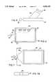
- FIG. 1is an illustration of a single prism optically connected to a waveguide and showing the characteristics of light rays
- FIG. 1Ais an alternate embodiment of a waveguide
- FIG. 2illustrates the light distribution output of the invention about two orthogonal axes
- FIG. 3is a cross sectional view illustrating the geometries of the prism and waveguide
- FIGS. 4A and 4Bis an alternate embodiment of a prism
- FIG. 4Cis a further alternate embodiment of a prism
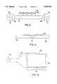
- FIG. 5illustrates a waveguide and a prism in combination with a negative lens structure
- FIG. 6is a plan view of the invention where the prisms are illustrated as a single sheet for simplicity purposes in combination with a point light source;
- FIG. 7is a plan view of the invention in combination with a point light source and a light source homogenizer
- FIG. 7Ais an elevation view at the input face of a light source homogenizer
- FIG. 8illustrates the invention in combination with a tapered input waveguide, an involute reflector and an array of negative lenses
- FIG. 9is an elevation view of a single light source in combination with two light directing structures
- FIG. 10is a plan view of light directing structure remotely located from a light source.
- FIG. 11is an elevation view of the invention optimized for illuminatin from the ceiling of a large flat object on the wall.
- One of the basic building blocks of the apparatus according to the inventionis a prism optically coupled to a waveguide. While the apparatus typically may contain hundreds or thousands of prisms arranged in some pattern or array, it is instructive to consider one prism in detail.
- Waveguide 40may be a light pipe, light wedge or any other structure known to those skilled in the art. It may have planar surfaces or alternatively may have non-planar sectioned surfaces as shown in FIG. 1A. For simplicity, and for descriptive purposes, but by no means intended to be limiting in nature, waveguide 40 is illustrated as being planar, and the microprisms 42 discussed below are referenced interfacing with a planar waveguide. As is well known to those skilled in the art, total internal reflection occurs if light within a medium strikes a boundary and bounces back into the medium.
- the index of refraction of the mediumhas to be higher than the index of refraction for the material on the other side of the boundary, and the angle of reflection must obey Snell's Law.
- the material outside the waveguide 40is air, with an index of refraction of one.
- the inventiondoes not require this, however, and may be practiced with materials other than air outside the waveguide.
- Light rays emanating from light source 37are bound by a "critical angle" within waveguide 40 as determined by Snell's Law.
- Light rays 110 or 111would be totally internally reflected within waveguide 40.
- Prism 42has an index of refraction approximately equal to or greater than the index of waveguide 40, and ray 110 and 111 are able to exit waveguide 40 and enter prism 42. This situation exists whether prism 42 is integrally formed with waveguide 40 or whether it is separately formed and then integrated with waveguide 40 using an adhesive or other suitable means.
- the range of angles of raysis related to the distribution of angles of light rays within waveguide 40. Because the rays within the waveguide are constrained, the rays exiting the prism are found mostly in a fairly narrowly constrained range of angles. Accordingly, this leads to the result that relatively undirected light can be coupled into waveguide 40 and a substantial portion of that light exits prism 42 as a directed light source.
- First face 114preferably is planar (this, however, would not be true for waveguides as shown in FIG. 1A) so as to have intimate optical coupling with the planar face of waveguide 40.
- Second face 32need not be absolutely planar, but could be curved somewhat or could be faceted, and still bring about the interesting results described; for that reason, it might be said that second face 32 is merely substantially planar.
- Third face 36likewise need not be absolutely planar. It can also be formed into either a convex, concave lens, and even an aspherical lens without departing from the results described.
- third face 36For a broadband light source, it is desired that the surface of third face 36 be more or less perpendicular to the desired light exit direction. This minimizes refraction of the exiting light; thereby minimizing the breaking up of a white light into colors.
- third face 36has a region tangent to a plane perpendicular to the desired light output direction, a terminology that embraces the possibility that the face might be planar or might be a lens.
- Those skilled in the artwill appreciate that nothing in this discussion demands any particular shape to the fourth face 115. In this embodiment, the control of the light output would be in only one viewing direction. In a preferred embodiment, however, fourth face 115 is also used to reflect light from the waveguide 40 using the same principles as face 32.
- fifith face 120 and sixth face 122also reflect light rays exiting from waveguide 40.
- a cross section view of the preferred embodiment of prism 42is shown in FIGS. 4A and 4B and disclosed in detail in referenced patent application Ser. No. 08/242,525.
- light rays traveling in different directions within waveguide 40will enter prism 42 and reflect off all prism faces. This situation arises when multiple light sources are used or where reflective material recycles light back into the waveguide as shown in FIGS. 6 and 7.
- This embodimentis preferred because it provides for control of the light distribution, both in intensity and direction, about two viewing axes, xz and yz, as shown in FIG. 2 and provides for efficient extraction of light from waveguide 40.
- prisms 42there is no requirement, other than perhaps ease of fabrication or adaptation to a particular light pattern, that all prisms 42 be identically shaped or evenly shaped. As set forth in the referenced patent applications, the spacing of prisms 42 may vary over the expanse of the waveguide to accommodate the distance of a prism 42 from the light source. Furthermore, prisms 42 may attach to waveguide 40 in selected regions so as to only allow light to escape waveguide 40 at selectively desired locations as dictated by the application. Also, the angles of prisms 42 may be provided over some distribution to yield more light at one particular exit angle and less at other exit angles, or to yield intentionally asymmetric spatial distributions of exiting light.
- the inventionmay be applied to many different applications, from automobile headlamps to lighting for an galleries, it is desirable to be able to vary the orientation of prisms 42 with respect to waveguide 40 to bring about a particular desired light distribution output.
- FIG. 3We will assume for simplicity that the index of refraction of prism 42 is equal to the index of refraction of waveguide 40. Snell's Law determines the angular spread of the light propagating in waveguide 40 with respect to the critical angle ⁇ c .
- light ray 20represents the median ray of the light output distribution.
- median light ray 20reflects off the second face 32 and exits prism 42 at an angle perpendicular to the tangent of the third face 36 and at an angle ⁇ with respect to second face 32.
- the directional output of median light ray 20also forms an angle ⁇ with respect to the surface 33 of waveguide 40.
- Angle ⁇is a function of the particular lighting application which would specify some light distribution output pattern.
- a simple relationshipexists between the desired angle of the light output ⁇ with the tilt angle, ⁇ , second face 32 forms with the surface 33 of waveguide 40.
- the third or top face 36is preferably perpendicular to the exit direction for the light, to avoid refraction of the output light into colors.
- the light sourceis narrow band in nature, such as a LED or laser, however, the above equation for angle ⁇ does not appliy because the median light ray 20 is not restricted to exit the prism 42 at an angle perpendicular to the tangent of the third face 36.
- FIG. 4shows alternative prism shapes 42A, 42B for the cross section of FIG. 1. It should be appreciated from these figures that the first face of the prism (coupled with the waveguide 40) is planar, but the second face 32A and 32B need merely be substantially planar. Depending on fabrication techniques and the desired light spill pattern the second face 32A and 32B could be curved or could be planar in two slightly different adjoining planes, without departing from the invention.
- FIG. 5shows a cross section of a prisms 42 in optical cooperation with a corresponding concave lens 39.
- a lens 39would correspond with each prism 42.
- the light output of prism 41is broadened to match the requirements of the particular application.
- a prism with an index of refraction of 1.45the light output distribution is +/- 35 degrees and a properly positioned de-focusing element, such as a concave lens 39, would provide a greater angular spread to the light distribution.
- This embodimentcould be advantageously used in a commercial lighting application where the preferred angular light distribution is +/- 60 degrees.
- scattering elementseither internal or external to prisms 42, may be used to broaden the output distribution, but with a loss of efficiency
- FIG. 6represents in plan view an array of light directing prisms 42 attached to a waveguide 40 which is optically coupled with a reflector arc light source 44, such as a metal halide lamp, at one edge 21.
- the lamp 44is positioned substantially a focal length away from the edge to allow the focused rays to couple efficiently into waveguide 40.
- lamp 44also comprises a light filtering device to selectively transmit and or reflect various spectural content of the lamp.
- light reflecting means 45such as specular or diffusive reflectors, define an aperture 47 along edge 21.
- reflecting means 45is also employed along the oppositely disposed edge of waveguide 40 to recycle light rays back into waveguide 40 that did not escape into prisms 42.
- a light source homogenizer 46In order to improve the uniformity of the light emitted from the waveguide 40, a light source homogenizer 46, preferably made of the same material as waveguide 40, allows the light rays from point light source 44 to uniformly fill the width of waveguide 40 shown in FIG. 7. This embodiment prevents uneven light brightness within waveguide 40 and results in a more uniform extraction of light from waveguide 40 by prisms 42.
- Light source homogenizer 46may be trapezoid-shaped or any other appropriate shape.
- a light reflecting material 45, specular or diffusive in nature, at the end away from light source 44may also be employed to recycle light.
- the light sourcemay be a parabolically focused short arc light source. Alternatively the shape of the light source reflector may be modified to uniformly fill waveguide structure 40 without the need for homogenizer 46.
- FIG. 7Ashows head-on the input face 43 of the trapezoid of FIG. 7.
- the input face 43need not be square but need merely be selected to be larger than the spot of light from the parabolic reflector.
- FIG. 8shows a shallow light fixture according to the invention using two extended light sources 37 and an array of concave lenses, together with trapezoid prism input structures 48 and arcuate reflectors 49.
- a reflective materialmay be substituted for one of the two trapezoidal prism input structure 48, light source 37 and reflector 49 combination to recycle light within waveguide 40.
- the trapezoidal prisms 48are tapered sections optically coupled with waveguide 40 which gather light from the extended light sources through a fairly large area, and through TIR the light is guided into the thin main waveguide 40. Because the smallest commercially available fluorescent bulbs are 10-12 mm, the tapered structure is needed to reduce the thickness of waveguide 40 so that waveguide 40 has a thickness much less than dictated by the diameter of the light source.
- an involute or arcuate-shaped reflector 49is preferred to avoid redirection of light back to the source.
- Reflector 49redirects the light that was not directly coupled into prism 48, and through one or two reflections the light has additional opportunities to enter prism 48.
- Alternate configurations of reflector 49are possible as is known to those skilled in the art.
- An array of negative lens structures 39may be used to efficiently spread the light output of prisms 42 to a wider distribution angle. If the diameter of light source 37 is d L and the height of the input face of trapezoid prism 48 is D, a typical ratio is D : d L of about 2:1.
- the waveguide thickness d Wis much less than d L , and may be 2 mm.
- this structureoffers previously unavailable architectural opportunities.
- the light fixtureis quite shallow and so does not require a thick ceiling.
- the dropped ceilingneed not be positioned very far down from the higher fixed ceiling, therefore offering cost-effective building techniques, heretofore unavailable because of bulky lighting fixtures.
- Other benefitsinclude improved light uniformity over two dimensions, less glare in peripheral vision of those in the space being illuminated, more efficient use of the light since it can be directed to the areas of interest utilizing appropriately shaped prisms and lenses.
- the prism coverage and sizemay be varied across the waveguide to provide uniform illumination in the target area.
- multiple waveguides structures 40may share a common light source 37. This arrangement increases the light efficiency since more of the light from light source 37 is directly coupled to one or another of the adjacent waveguides 40.
- reflectorssurround light source 37 to couple otherwise stray light to the waveguides through one or more reflections.
- additional waveguides 40could be coupled to light source 37 and additional light sources could be coupled to other available edges of waveguide 40.
- FIG. 10repesents an array of light directing prisms 42, waveguide 40, in combination designated as a light directing structure 53 and an additional waveguide structure 54 optically coupled to a light source 55.
- structure 53may be relatively inaccessible to users and yet the light source 55 can be accessible. Such an occurrence may arise when structure 53 may be in a ceiling and the light source 55 may be at floor level to facilitate maintenance of the light source 55.
- Another examplewould be roadway signage, where structure 53 illuminates road signs high above the roadway.
- light source 55could be at the road surface.
- One advantageis easier servicing when the lamp 55 must be replaced.
- Another advantageis that the heat source is removed from the illumination source.
- additional waveguide structure 54is a bundle of optical fibers arranged along an edge of waveguide 40.
- the fiber bundlecould optionally be replaced by other waveguide structures which transmit light with low loss through total internal reflection.
- more than one light directing structurecould be coupled to the light source. This could be useful in automotive lighting as well as commercial room lighting. Preferably at least 60% and more preferably 70% of the light from the source is distributed to the desired location.
- FIG. 11shows a light source according to the invention optimized for illumination from the ceiling of a large flat object 22 on a wall.
- Most light fixturesfail to provide appropriate lighting for such objects.
- This inventionallows for asymmetric light distribution as required by this application. This is accomplished by selecting the shapes of the prisms of the film, and by selecting how many prisms of each shape are provided on the film.
- a structure 53 only "d" inches wide, of shallow vertical dimension,can nonetheless provide even illumination across an object (e.g. a painting) that is "D" inches tall where D is much larger than d.
Landscapes
- Physics & Mathematics (AREA)
- General Physics & Mathematics (AREA)
- Optics & Photonics (AREA)
- Engineering & Computer Science (AREA)
- General Engineering & Computer Science (AREA)
- Optical Elements Other Than Lenses (AREA)
- Optical Couplings Of Light Guides (AREA)
- Planar Illumination Modules (AREA)
- Instruments For Viewing The Inside Of Hollow Bodies (AREA)
- Light Guides In General And Applications Therefor (AREA)
- Non-Portable Lighting Devices Or Systems Thereof (AREA)
- Road Signs Or Road Markings (AREA)
Abstract
Description
This application is a continuation-in-part of three U.S. patent applications: Appl. No. 08/149,219, filed Nov. 5, 1993, now U.S. Pat. No. 5,424,460 Appl. No. 08/242,525, filed May 13, 1994, now U.S. Pat. No. 5,428,468 and Appl. No. 08/321,368, filed Oct. 11, 1994, now pending each of which is hereby incorporated by reference.
The invention relates generally to optical structures which receive light from relatively uncontrolled sources in terms of directivity and uniformity and emit a spatially-controlled light distribution with respect to the two orthogonal axes defined with respect to the direction of propagation of the light source, and relates particularly to such structures utilized for residential, commercial and industrial lighting applications.
The ability to control the light distribution from various light sources, such as a point source or an extended source about two orthogonal axes has not been successfully implemented in a unitary structure. For example, in typical office lighting applications using fluorescent lighting, no single element is able to simultaneously control the light distribution about two axes. A fluorescent light contains a single reflector which is only able to provide directivity along one axis. Alternatively, if two axes control is attempted with the present technology, a reflector and luminaries are required. This combination, however, provides efficiency losses, suffers from non-uniformity and creates a complex and bulky arrangement.
It would be desirable to have a relatively robust, lightweight and efficient optical structure that would fit easily within a small form factor and that would be able to receive light from any light generating means. Such a structure would permit new and useful ways to provide directed light distribution for various lighting applications.
The present invention provides for an integrated light directing structure which provides a spatially-directed light output along two orthogonal dimensions as required by the particular application.
The invention comprises a light source in combination with an optical structure which comprises a waveguide component which accepts the light generated by the light source and transports the light via total internal reflection (TIR). Optically coupled to or integrally formed with a surface of the waveguide are a multiplicity of prisms. Each prism, due to its index of refraction, provides an aperture where light may escape the waveguide rather than remain confined due to total internal reflection. The light escaping the waveguide is reflected from a side face of the prism, and redirected in the desired output direction.
The geometry of the prism can be optimized to direct the output at any desired angle from the surface of the waveguide. Advantageously, the optical structure, which might be characterized as a light directing structure, can have a narrow profile, and the waveguide structure is suitable to allow light coupling along an light input edge, or along several light input edges. Furthermore, there is no restriction on the distribution and uniformity of the light input to the waveguide.
There are many illumination applications that can take advantage of this invention. Such applications exist in commercial and residential markets and in various industries such as the automotive industry and the aerospace industry. Exemplary residential and commercial applications include low profile interior and exterior lighting such as spotlights, room or office lighting and accent lighting. Exemplary automotive applications include low profile car headlights and taillights, low profile interior car lights such as reading lights and map lights and light sources for dashboard displays and instrument panels.
The invention will be described with respect to a drawing of several figures, of which:
FIG. 1 is an illustration of a single prism optically connected to a waveguide and showing the characteristics of light rays;
FIG. 1A is an alternate embodiment of a waveguide;
FIG. 2 illustrates the light distribution output of the invention about two orthogonal axes;
FIG. 3 is a cross sectional view illustrating the geometries of the prism and waveguide;
FIGS. 4A and 4B is an alternate embodiment of a prism;
FIG. 4C is a further alternate embodiment of a prism;
FIG. 5 illustrates a waveguide and a prism in combination with a negative lens structure;
FIG. 6 is a plan view of the invention where the prisms are illustrated as a single sheet for simplicity purposes in combination with a point light source;
FIG. 7 is a plan view of the invention in combination with a point light source and a light source homogenizer;
FIG. 7A is an elevation view at the input face of a light source homogenizer;
FIG. 8 illustrates the invention in combination with a tapered input waveguide, an involute reflector and an array of negative lenses;
FIG. 9 is an elevation view of a single light source in combination with two light directing structures;
FIG. 10 is a plan view of light directing structure remotely located from a light source; and
FIG. 11 is an elevation view of the invention optimized for illuminatin from the ceiling of a large flat object on the wall.
Where possible, like elements have been shown with like reference numerals.
One of the basic building blocks of the apparatus according to the invention is a prism optically coupled to a waveguide. While the apparatus typically may contain hundreds or thousands of prisms arranged in some pattern or array, it is instructive to consider one prism in detail.
With reference to FIG. 1, light rays, as exemplified bylight rays waveguide 40. Waveguide 40 may be a light pipe, light wedge or any other structure known to those skilled in the art. It may have planar surfaces or alternatively may have non-planar sectioned surfaces as shown in FIG. 1A. For simplicity, and for descriptive purposes, but by no means intended to be limiting in nature,waveguide 40 is illustrated as being planar, and themicroprisms 42 discussed below are referenced interfacing with a planar waveguide. As is well known to those skilled in the art, total internal reflection occurs if light within a medium strikes a boundary and bounces back into the medium. For such a reflection to occur, the index of refraction of the medium has to be higher than the index of refraction for the material on the other side of the boundary, and the angle of reflection must obey Snell's Law. For simplicity of analysis one assumes that the material outside thewaveguide 40 is air, with an index of refraction of one. The invention does not require this, however, and may be practiced with materials other than air outside the waveguide.
Light rays emanating fromlight source 37 are bound by a "critical angle" withinwaveguide 40 as determined by Snell's Law.Light rays prism 42, would be totally internally reflected withinwaveguide 40.Prism 42 has an index of refraction approximately equal to or greater than the index ofwaveguide 40, andray waveguide 40 and enterprism 42. This situation exists whetherprism 42 is integrally formed withwaveguide 40 or whether it is separately formed and then integrated withwaveguide 40 using an adhesive or other suitable means. Afterray 111 entersprism 42, it internally reflects to makeray 112. Similarly,ray 110 undergoes a reflection to make ray 113. The range of angles of rays, such as 112 and 113, is related to the distribution of angles of light rays withinwaveguide 40. Because the rays within the waveguide are constrained, the rays exiting the prism are found mostly in a fairly narrowly constrained range of angles. Accordingly, this leads to the result that relatively undirected light can be coupled intowaveguide 40 and a substantial portion of that light exitsprism 42 as a directed light source.
Those skilled in the art will appreciate that some of the faces ofprism 42 are critical.First face 114 preferably is planar (this, however, would not be true for waveguides as shown in FIG. 1A) so as to have intimate optical coupling with the planar face ofwaveguide 40.Second face 32 need not be absolutely planar, but could be curved somewhat or could be faceted, and still bring about the interesting results described; for that reason, it might be said thatsecond face 32 is merely substantially planar.Third face 36 likewise need not be absolutely planar. It can also be formed into either a convex, concave lens, and even an aspherical lens without departing from the results described. For a broadband light source, it is desired that the surface ofthird face 36 be more or less perpendicular to the desired light exit direction. This minimizes refraction of the exiting light; thereby minimizing the breaking up of a white light into colors. One way to describe the desired orientation is thatthird face 36 has a region tangent to a plane perpendicular to the desired light output direction, a terminology that embraces the possibility that the face might be planar or might be a lens. Those skilled in the art will appreciate that nothing in this discussion demands any particular shape to thefourth face 115. In this embodiment, the control of the light output would be in only one viewing direction. In a preferred embodiment, however,fourth face 115 is also used to reflect light from thewaveguide 40 using the same principles asface 32. In the most preferred embodiment,fifith face 120 andsixth face 122 also reflect light rays exiting fromwaveguide 40. A cross section view of the preferred embodiment ofprism 42 is shown in FIGS. 4A and 4B and disclosed in detail in referenced patent application Ser. No. 08/242,525. In this most preferred embodiment, light rays traveling in different directions withinwaveguide 40 will enterprism 42 and reflect off all prism faces. This situation arises when multiple light sources are used or where reflective material recycles light back into the waveguide as shown in FIGS. 6 and 7. This embodiment is preferred because it provides for control of the light distribution, both in intensity and direction, about two viewing axes, xz and yz, as shown in FIG. 2 and provides for efficient extraction of light fromwaveguide 40. Furthermore, none of the foregoing discussion demands that any of the faces ofprism 42 join in a simple edge; if something about the fabrication technique, for example, required that the edge connection between faces be beveled or rounded, this would not depart from the invention. In addition, it is not necessary thatfirst face 114 andthird face 36 be parallel. Those skilled in the art will appreciate that in some applications, a slight taper might be preferred to distribute the light output fromprisms 42.
There is no requirement, other than perhaps ease of fabrication or adaptation to a particular light pattern, that allprisms 42 be identically shaped or evenly shaped. As set forth in the referenced patent applications, the spacing ofprisms 42 may vary over the expanse of the waveguide to accommodate the distance of aprism 42 from the light source. Furthermore,prisms 42 may attach to waveguide 40 in selected regions so as to only allow light to escapewaveguide 40 at selectively desired locations as dictated by the application. Also, the angles ofprisms 42 may be provided over some distribution to yield more light at one particular exit angle and less at other exit angles, or to yield intentionally asymmetric spatial distributions of exiting light.
Because the invention may be applied to many different applications, from automobile headlamps to lighting for an galleries, it is desirable to be able to vary the orientation ofprisms 42 with respect towaveguide 40 to bring about a particular desired light distribution output. Reference is now made to FIG. 3. We will assume for simplicity that the index of refraction ofprism 42 is equal to the index of refraction ofwaveguide 40. Snell's Law determines the angular spread of the light propagating inwaveguide 40 with respect to the critical angle θc. Preferably, and in the case of a broadband light source, defined as 400-700 nm, light ray 20 represents the median ray of the light output distribution. For illustration purposes only, median light ray 20 reflects off thesecond face 32 and exitsprism 42 at an angle perpendicular to the tangent of thethird face 36 and at an angle β with respect tosecond face 32. The directional output of median light ray 20 also forms an angle θ with respect to thesurface 33 ofwaveguide 40. Angle θ is a function of the particular lighting application which would specify some light distribution output pattern. For a waveguide having light rays from all angles from 0° to θc, a simple relationship exists between the desired angle of the light output θ with the tilt angle, φ,second face 32 forms with thesurface 33 ofwaveguide 40. Angle θ=2φ-45+θc /2 where θc is the critical angle defined by Snell's Law and equals sin-1 (n2 /n1) where n1 equals the index of refraction ofwaveguide 40 and and n2 equals the index of refraction of the material outside the waveguide 40 (for example, in the case of air, n2 =1.00). A similar relationship can be derived where the index of refraction ofwaveguide 40 andprism 42 do not match.
Furthermore, the third ortop face 36 is preferably perpendicular to the exit direction for the light, to avoid refraction of the output light into colors. In the case where the light source is narrow band in nature, such as a LED or laser, however, the above equation for angle θ does not appliy because the median light ray 20 is not restricted to exit theprism 42 at an angle perpendicular to the tangent of thethird face 36.
FIG. 4 shows alternative prism shapes 42A, 42B for the cross section of FIG. 1. It should be appreciated from these figures that the first face of the prism (coupled with the waveguide 40) is planar, but thesecond face second face
FIG. 5 shows a cross section of aprisms 42 in optical cooperation with a correspondingconcave lens 39. As would be obvious, ifmultiple prisms 42 were arranged in any specific pattern, alens 39 would correspond with eachprism 42. In such an embodiment, the light output of prism 41 is broadened to match the requirements of the particular application. For example, a prism with an index of refraction of 1.45, the light output distribution is +/- 35 degrees and a properly positioned de-focusing element, such as aconcave lens 39, would provide a greater angular spread to the light distribution. This embodiment could be advantageously used in a commercial lighting application where the preferred angular light distribution is +/- 60 degrees. Alternatively, scattering elements, either internal or external toprisms 42, may be used to broaden the output distribution, but with a loss of efficiency
An alternate embodiment of the invention is illustrated in FIG. 6 which represents in plan view an array oflight directing prisms 42 attached to awaveguide 40 which is optically coupled with a reflectorarc light source 44, such as a metal halide lamp, at oneedge 21. Thelamp 44 is positioned substantially a focal length away from the edge to allow the focused rays to couple efficiently intowaveguide 40. Preferably,lamp 44 also comprises a light filtering device to selectively transmit and or reflect various spectural content of the lamp. For example, ifwaveguide 40 is a plastic material, infared light may provide unwanted heat buildup. Additionally, light reflecting means 45, such as specular or diffusive reflectors, define an aperture 47 alongedge 21. Preferably, reflecting means 45 is also employed along the oppositely disposed edge ofwaveguide 40 to recycle light rays back intowaveguide 40 that did not escape intoprisms 42.
In order to improve the uniformity of the light emitted from thewaveguide 40, alight source homogenizer 46, preferably made of the same material aswaveguide 40, allows the light rays from pointlight source 44 to uniformly fill the width ofwaveguide 40 shown in FIG. 7. This embodiment prevents uneven light brightness withinwaveguide 40 and results in a more uniform extraction of light fromwaveguide 40 byprisms 42. Light source homogenizer 46 may be trapezoid-shaped or any other appropriate shape. Alight reflecting material 45, specular or diffusive in nature, at the end away fromlight source 44 may also be employed to recycle light. The light source may be a parabolically focused short arc light source. Alternatively the shape of the light source reflector may be modified to uniformly fillwaveguide structure 40 without the need forhomogenizer 46.
FIG. 7A shows head-on theinput face 43 of the trapezoid of FIG. 7. The input face 43 need not be square but need merely be selected to be larger than the spot of light from the parabolic reflector.
FIG. 8 shows a shallow light fixture according to the invention using twoextended light sources 37 and an array of concave lenses, together with trapezoidprism input structures 48 andarcuate reflectors 49. Alternatively, a reflective material may be substituted for one of the two trapezoidalprism input structure 48,light source 37 andreflector 49 combination to recycle light withinwaveguide 40. Thetrapezoidal prisms 48 are tapered sections optically coupled withwaveguide 40 which gather light from the extended light sources through a fairly large area, and through TIR the light is guided into the thinmain waveguide 40. Because the smallest commercially available fluorescent bulbs are 10-12 mm, the tapered structure is needed to reduce the thickness ofwaveguide 40 so thatwaveguide 40 has a thickness much less than dictated by the diameter of the light source. To maximize the efficiency of transfer of light into the waveguide, an involute or arcuate-shapedreflector 49 is preferred to avoid redirection of light back to the source.Reflector 49 redirects the light that was not directly coupled intoprism 48, and through one or two reflections the light has additional opportunities to enterprism 48. Alternate configurations ofreflector 49 are possible as is known to those skilled in the art. An array ofnegative lens structures 39 may be used to efficiently spread the light output ofprisms 42 to a wider distribution angle. If the diameter oflight source 37 is dL and the height of the input face oftrapezoid prism 48 is D, a typical ratio is D : dL of about 2:1. The waveguide thickness dW is much less than dL, and may be 2 mm.
It should be appreciated that this structure offers previously unavailable architectural opportunities. For example, the light fixture is quite shallow and so does not require a thick ceiling. Where dropped ceilings are used the dropped ceiling need not be positioned very far down from the higher fixed ceiling, therefore offering cost-effective building techniques, heretofore unavailable because of bulky lighting fixtures. Other benefits include improved light uniformity over two dimensions, less glare in peripheral vision of those in the space being illuminated, more efficient use of the light since it can be directed to the areas of interest utilizing appropriately shaped prisms and lenses. Furthermore, the prism coverage and size may be varied across the waveguide to provide uniform illumination in the target area.
While one embodiment may comprise two extended light sources as discussed above, an alternative as shown in FIG. 9 may be used. Here,multiple waveguides structures 40 may share acommon light source 37. This arrangement increases the light efficiency since more of the light fromlight source 37 is directly coupled to one or another of theadjacent waveguides 40. Preferably, reflectors surroundlight source 37 to couple otherwise stray light to the waveguides through one or more reflections. As would be obvious to those skilled in the art,additional waveguides 40 could be coupled tolight source 37 and additional light sources could be coupled to other available edges ofwaveguide 40.
FIG. 10 repesents an array oflight directing prisms 42,waveguide 40, in combination designated as alight directing structure 53 and anadditional waveguide structure 54 optically coupled to alight source 55. This permitslight source 55 to be remote fromstructure 53. For example,structure 53 may be relatively inaccessible to users and yet thelight source 55 can be accessible. Such an occurrence may arise whenstructure 53 may be in a ceiling and thelight source 55 may be at floor level to facilitate maintenance of thelight source 55. Another example would be roadway signage, wherestructure 53 illuminates road signs high above the roadway. Here,light source 55 could be at the road surface. One advantage is easier servicing when thelamp 55 must be replaced. Another advantage is that the heat source is removed from the illumination source. One example ofadditional waveguide structure 54 is a bundle of optical fibers arranged along an edge ofwaveguide 40. The fiber bundle could optionally be replaced by other waveguide structures which transmit light with low loss through total internal reflection. Depending on the source, more than one light directing structure could be coupled to the light source. This could be useful in automotive lighting as well as commercial room lighting. Preferably at least 60% and more preferably 70% of the light from the source is distributed to the desired location.
FIG. 11 shows a light source according to the invention optimized for illumination from the ceiling of a largeflat object 22 on a wall. Most light fixtures fail to provide appropriate lighting for such objects. This invention allows for asymmetric light distribution as required by this application. This is accomplished by selecting the shapes of the prisms of the film, and by selecting how many prisms of each shape are provided on the film. Astructure 53 only "d" inches wide, of shallow vertical dimension, can nonetheless provide even illumination across an object (e.g. a painting) that is "D" inches tall where D is much larger than d.
Claims (26)
1. An apparatus for directing light in a desired direction, the apparatus comprising:
a) a first waveguide having a first edge and a second edge opposed thereto, said first waveguide having an index of refraction higher than that of its surroundings;
b) a quadrilateral second waveguide, said second waveguide having an index of refraction higher than that of its surroundings and having first, second, third, and fourth edges, the first edge of the second waveguide optically coupled with and sized to fit the first edge of the first waveguide; the fourth edge opposed to the first edge of the second waveguide, said fourth edge defining an input face; said second and third edges connecting said first and fourth edges, said second and third edges each defining respective acute angles with said first edge; and
c) a multiplicity of prisms optically coupled with a face of said planar first waveguide.
2. The apparatus of claim 1 further comprising a parabolically focused light source optically coupled to said input face.
3. The apparatus of claim 1 wherein the first and second waveguides are integrally formed.
4. The apparatus of claim 1 wherein the first waveguide is substantially rectangular.
5. A light directing apparatus comprising:
a) a first waveguide having a first edge and a second edge opposed thereto, said first waveguide having an index of refraction higher than that of its surroundings;
b) a substantially trapezoidal first prism, said first prism having an index of refraction higher than that of its surroundings, the trapezoidal cross section of the first prism defining first and second parallel sides and third and fourth sides, the prism face containing said first side optically coupled with and sized to fit the first edge of the waveguide; the prism face containing said second side being larger in area than said prism face containing said first side and defining a first input face; said second and third sides each defining respective acute angles with said second side; and
c) a multiplicity of second prisms optically coupled with a face of said planar first waveguide.
6. The apparatus of claim 5 further comprising a first extended light source optically coupled with the first input face.
7. The apparatus of claim 6 further comprising a first involute reflector surrounding said first light source and mechanically coupled with said first input face thereby defining a first enclosure about said first light source.
8. The apparatus of claim 5 wherein the waveguide and first prism are integrally formed.
9. The apparatus of claim 5 further comprising a substantially trapezoidal third prism, said third prism having an index of refraction higher than that of its surroundings, the trapezoidal cross section of the third prism defining first and second parallel sides and third and fourth sides, the prism face containing said first side optically coupled with and sized to fit the second edge of the waveguide; the prism face containing said second side being larger in area than said prism face containing said first side and defining a second input face; said second and third sides each defining respective acute angles with said second side.
10. The apparatus of claim 9 further comprising a second extended light source optically coupled with the second input face.
11. The apparatus of claim 10 further comprising a second involute reflector surrounding said second light source and mechanically coupled with said second input face thereby defining a second enclosure about said second light source.
12. The apparatus of claim 5 wherein the waveguide and second prism are integrally formed.
13. An apparatus for directing light in a desired direction, the apparatus comprising:
a) a waveguide having an edge for coupling to a light source, the wave guide having an index of refraction r1, the surroundings of the waveguide having an index of refraction no, the ratio of no to n1 defining a ratio r1 ; the waveguide having first and second sides;
b) a multiplicity of prisms each having a respective index of refraction n2, the ratio of n0 to n2 defining a ratio r2, the ratio r2 approximately equal to r1, each prism having at least first, second, and third faces; and
c) the first, second, and third prism faces characterized in that the first face is optically coupled to said waveguide; the second face is substantially planar, and defines a tilt angle with respect to said first side, the third face of each prism having a portion tangent to a plane substantially perpendicular to the desired light output direction.
14. The apparatus of claim 13 wherein the first and second sides of the waveguide are parallel.
15. The apparatus of claim 13 wherein the waveguide and prisms are integrally formed of the same material.
16. The apparatus of claim 13 wherein the waveguide and prisms are formed separately and attached so as to be optically coupled.
17. The apparatus of claim 13 wherein the desired light output direction is substantially perpendicular to the first side of the waveguide.
18. The apparatus of claim 13 wherein the second face of each prism is planar.
19. The apparatus of claim 13 wherein the third face of each prism is planar.
20. The apparatus of claim 13 wherein the third face of each prism is a convex lens.
21. The apparatus of claim 13 wherein the third face of each prism is a concave lens.
22. The apparatus of claim 13 wherein the third face of each prism is an aspheric lens.
23. An apparatus for directing light in a desired direction, the apparatus comprising:
a) a first waveguide having a first edge and a second edge opposed thereto, said first waveguide having an index of refraction higher than that of its surroundings;
b) a second waveguide optically coupled to the first edge; and
c) a multiplicity of prisms optically coupled with a face of said planar first waveguide.
24. The apparatus of claim 23 further comprising a reflecting sheet at the second edge of the first waveguide disposed to reflect light within the first waveguide.
25. The apparatus of claim 23 further comprising a light source optically coupled with said second waveguide and remote from said first waveguide.
26. The apparatus of claim 23 wherein the second waveguide is a bundle of fiber optic cables.
Priority Applications (18)
| Application Number | Priority Date | Filing Date | Title |
|---|---|---|---|
| US08/376,709US5555329A (en) | 1993-11-05 | 1995-01-23 | Light directing optical structure |
| EP98118856AEP0886103B1 (en) | 1995-01-23 | 1996-01-19 | Light directing optical structure |
| DE69603452TDE69603452T2 (en) | 1995-01-23 | 1996-01-19 | LIGHT-GUIDING OPTICAL STRUCTURE |
| CA002210575ACA2210575C (en) | 1995-01-23 | 1996-01-19 | Light directing optical structure |
| AT98118856TATE208876T1 (en) | 1995-01-23 | 1996-01-19 | LIGHT-DIRECTING OPTICAL STRUCTURE |
| JP52291596AJP3529387B2 (en) | 1995-01-23 | 1996-01-19 | Light directing optical structure |
| PCT/US1996/000619WO1996023166A1 (en) | 1995-01-23 | 1996-01-19 | Light directing optical structure |
| AT96903529TATE182664T1 (en) | 1995-01-23 | 1996-01-19 | LIGHT-DIRECTING OPTICAL STRUCTURE |
| EP96903529AEP0805936B1 (en) | 1995-01-23 | 1996-01-19 | Light directing optical structure |
| AU47590/96AAU4759096A (en) | 1995-01-23 | 1996-01-19 | Light directing optical structure |
| KR1019970704756AKR100474233B1 (en) | 1995-01-23 | 1996-01-19 | Optical sight optical structure |
| CN96191569ACN1105862C (en) | 1995-01-23 | 1996-01-19 | Light directing optical structure |
| DE69617046TDE69617046T2 (en) | 1995-01-23 | 1996-01-19 | Light guiding optical structure |
| TW085100766ATW297867B (en) | 1995-01-23 | 1996-01-23 | |
| US08/691,073US5761355A (en) | 1993-11-05 | 1996-08-01 | Light directing optical structure |
| US08/782,133US5748828A (en) | 1993-11-10 | 1997-01-13 | Color separating backlight |
| MXPA/A/1997/005276AMXPA97005276A (en) | 1995-01-23 | 1997-07-11 | Light directing optical structure |
| JP2003042300AJP2004046071A (en) | 1995-01-23 | 2003-02-20 | Light-beam directional optical structure |
Applications Claiming Priority (4)
| Application Number | Priority Date | Filing Date | Title |
|---|---|---|---|
| US08/149,219US5396350A (en) | 1993-11-05 | 1993-11-05 | Backlighting apparatus employing an array of microprisms |
| US08/242,525US5428468A (en) | 1993-11-05 | 1994-05-13 | Illumination system employing an array of microprisms |
| US32136894A | 1994-10-11 | 1994-10-11 | |
| US08/376,709US5555329A (en) | 1993-11-05 | 1995-01-23 | Light directing optical structure |
Related Parent Applications (4)
| Application Number | Title | Priority Date | Filing Date |
|---|---|---|---|
| US08/149,219Continuation-In-PartUS5396350A (en) | 1993-11-05 | 1993-11-05 | Backlighting apparatus employing an array of microprisms |
| US08/149,912Continuation-In-PartUS5424406A (en) | 1992-11-12 | 1993-11-10 | Dihydrochalcone derivatives which are hypoglycemic agents |
| US08/242,525Continuation-In-PartUS5428468A (en) | 1993-11-05 | 1994-05-13 | Illumination system employing an array of microprisms |
| US32136894AContinuation-In-Part | 1993-11-05 | 1994-10-11 |
Related Child Applications (2)
| Application Number | Title | Priority Date | Filing Date |
|---|---|---|---|
| US08/691,073ContinuationUS5761355A (en) | 1993-11-05 | 1996-08-01 | Light directing optical structure |
| US08/782,133Continuation-In-PartUS5748828A (en) | 1993-11-10 | 1997-01-13 | Color separating backlight |
Publications (1)
| Publication Number | Publication Date |
|---|---|
| US5555329Atrue US5555329A (en) | 1996-09-10 |
Family
ID=23486141
Family Applications (2)
| Application Number | Title | Priority Date | Filing Date |
|---|---|---|---|
| US08/376,709Expired - LifetimeUS5555329A (en) | 1993-11-05 | 1995-01-23 | Light directing optical structure |
| US08/691,073Expired - LifetimeUS5761355A (en) | 1993-11-05 | 1996-08-01 | Light directing optical structure |
Family Applications After (1)
| Application Number | Title | Priority Date | Filing Date |
|---|---|---|---|
| US08/691,073Expired - LifetimeUS5761355A (en) | 1993-11-05 | 1996-08-01 | Light directing optical structure |
Country Status (10)
| Country | Link |
|---|---|
| US (2) | US5555329A (en) |
| EP (2) | EP0886103B1 (en) |
| JP (2) | JP3529387B2 (en) |
| KR (1) | KR100474233B1 (en) |
| CN (1) | CN1105862C (en) |
| AT (2) | ATE182664T1 (en) |
| AU (1) | AU4759096A (en) |
| DE (2) | DE69603452T2 (en) |
| TW (1) | TW297867B (en) |
| WO (1) | WO1996023166A1 (en) |
Cited By (98)
| Publication number | Priority date | Publication date | Assignee | Title |
|---|---|---|---|---|
| US5761355A (en)* | 1993-11-05 | 1998-06-02 | Alliedsignal Inc. | Light directing optical structure |
| WO1999045317A1 (en) | 1998-03-03 | 1999-09-10 | Alliedsignal Inc. | A lenticular illumination system |
| US5995690A (en)* | 1996-11-21 | 1999-11-30 | Minnesota Mining And Manufacturing Company | Front light extraction film for light guiding systems and method of manufacture |
| US6185357B1 (en) | 1998-09-10 | 2001-02-06 | Honeywell International Inc. | Illumination system using edge-illuminated hollow waveguide and lenticular optical structures |
| US6234603B1 (en)* | 1995-12-14 | 2001-05-22 | Xerox Corporation | Sensing system for detecting presence of an ink container and level of ink therein |
| EP1106905A2 (en) | 1999-11-30 | 2001-06-13 | GEBRUEDER LUDWIG GmbH | Luminaire |
| US6347874B1 (en) | 2000-02-16 | 2002-02-19 | 3M Innovative Properties Company | Wedge light extractor with risers |
| US6428198B1 (en) | 1998-07-07 | 2002-08-06 | Alliedsignal Inc. | Display system having a light source separate from a display device |
| US6449439B1 (en)* | 1999-11-30 | 2002-09-10 | 3M Innovative Properties Company | Unitary light diffusing cavity |
| US6497939B1 (en)* | 1998-02-03 | 2002-12-24 | Nippon Zeon Co., Ltd. | Flat plate and light guide plate |
| US20030013304A1 (en)* | 2001-05-17 | 2003-01-16 | Optronx, Inc. | Method for forming passive optical coupling device |
| US20030032286A1 (en)* | 2001-05-17 | 2003-02-13 | Shrenik Deliwala | Anisotropic etching of optical components |
| US6576887B2 (en) | 2001-08-15 | 2003-06-10 | 3M Innovative Properties Company | Light guide for use with backlit display |
| US6592234B2 (en) | 2001-04-06 | 2003-07-15 | 3M Innovative Properties Company | Frontlit display |
| US6640029B1 (en)* | 1998-08-14 | 2003-10-28 | Eclair, Spol S R.O. | Light optical system, especially for information, advertising illumination or decorative purposes |
| US20040001421A1 (en)* | 2002-06-27 | 2004-01-01 | Fujitsu Limited | Optical irradiation head and information recording/reproducing device |
| US20040067038A1 (en)* | 2002-10-03 | 2004-04-08 | Dragoslav Popovic | Light guide and lateral illuminator |
| US6738051B2 (en) | 2001-04-06 | 2004-05-18 | 3M Innovative Properties Company | Frontlit illuminated touch panel |
| US6748125B2 (en) | 2001-05-17 | 2004-06-08 | Sioptical, Inc. | Electronic semiconductor control of light in optical waveguide |
| US20040114344A1 (en)* | 2001-02-23 | 2004-06-17 | Burtsev Vladimir Nikolayevich | Data display device |
| US20050072032A1 (en)* | 1995-06-27 | 2005-04-07 | Mccollum Timothy A. | Light emitting panel assemblies |
| US20050270798A1 (en)* | 2004-06-03 | 2005-12-08 | Eastman Kodak Company | Brightness enhancement film using a linear arrangement of light concentrators |
| US20050273968A1 (en)* | 2002-02-27 | 2005-12-15 | Bsh Bosch Und Siemens Hausgerate Gmbh | Vacuum cleaner with light guiding element |
| US20060104092A1 (en)* | 2004-11-12 | 2006-05-18 | Tsinghua University | Light guide device and a backlight module using the same |
| US20060104093A1 (en)* | 2004-11-18 | 2006-05-18 | Tsinghua University | Light guide device and a backlight module using the same |
| US20070041701A1 (en)* | 2005-08-18 | 2007-02-22 | Tsinghua University | Light guide plate and a backlight system |
| US20070058391A1 (en)* | 2005-09-14 | 2007-03-15 | Wilson Randall H | Light extraction layer |
| US20070230213A1 (en)* | 2006-03-28 | 2007-10-04 | Samsung Electronics Co., Ltd. | Backlight having all-in-one type light guide plate and method of manufacturing all-in-one type light guide plate |
| US20090064993A1 (en)* | 2007-09-10 | 2009-03-12 | Banyan Energy, Inc. | Solar energy concentrator |
| US20090067784A1 (en)* | 2007-09-10 | 2009-03-12 | Banyan Energy, Inc. | Compact optics for concentration, aggregation and illumination of light energy |
| WO2009141762A1 (en) | 2008-05-20 | 2009-11-26 | Koninklijke Philips Electronics N.V. | Optical element for asymmetric light distribution |
| US8412010B2 (en) | 2007-09-10 | 2013-04-02 | Banyan Energy, Inc. | Compact optics for concentration and illumination systems |
| US8705914B2 (en) | 2007-09-10 | 2014-04-22 | Banyan Energy, Inc. | Redirecting optics for concentration and illumination systems |
| US20140355302A1 (en)* | 2013-03-15 | 2014-12-04 | Cree, Inc. | Outdoor and/or Enclosed Structure LED Luminaire for General Illumination Applications, Such as Parking Lots and Structures |
| DE102013204021B4 (en)* | 2012-06-01 | 2015-02-19 | Automotive Lighting Reutlingen Gmbh | Light guide for a lighting device |
| US20150109820A1 (en)* | 2013-03-15 | 2015-04-23 | Cree, Inc. | Outdoor and/or Enclosed Structure LED Luminaire |
| US9291320B2 (en) | 2013-01-30 | 2016-03-22 | Cree, Inc. | Consolidated troffer |
| EP3026365A1 (en) | 2014-11-25 | 2016-06-01 | Marcelo Ymbern | Active sunlight redirection system |
| US9366799B2 (en) | 2013-03-15 | 2016-06-14 | Cree, Inc. | Optical waveguide bodies and luminaires utilizing same |
| US9366396B2 (en) | 2013-01-30 | 2016-06-14 | Cree, Inc. | Optical waveguide and lamp including same |
| US9389367B2 (en) | 2013-01-30 | 2016-07-12 | Cree, Inc. | Optical waveguide and luminaire incorporating same |
| US9442243B2 (en) | 2013-01-30 | 2016-09-13 | Cree, Inc. | Waveguide bodies including redirection features and methods of producing same |
| US9625638B2 (en) | 2013-03-15 | 2017-04-18 | Cree, Inc. | Optical waveguide body |
| US9645303B2 (en) | 2013-03-15 | 2017-05-09 | Cree, Inc. | Luminaires utilizing edge coupling |
| US9690029B2 (en) | 2013-01-30 | 2017-06-27 | Cree, Inc. | Optical waveguides and luminaires incorporating same |
| WO2017174110A1 (en) | 2016-04-04 | 2017-10-12 | Marcelo Ymbern | Active sunlight redirection system |
| US9798072B2 (en) | 2013-03-15 | 2017-10-24 | Cree, Inc. | Optical element and method of forming an optical element |
| US9869432B2 (en) | 2013-01-30 | 2018-01-16 | Cree, Inc. | Luminaires using waveguide bodies and optical elements |
| US9885821B2 (en) | 2015-06-01 | 2018-02-06 | Boe Technology Group Co., Ltd. | Backlight module and anti-peeping display device |
| US9920901B2 (en) | 2013-03-15 | 2018-03-20 | Cree, Inc. | LED lensing arrangement |
| US20180275384A1 (en)* | 2016-11-08 | 2018-09-27 | Lumus Ltd | Light-guide device with optical cutoff edge and corresponding production methods |
| US10145606B2 (en) | 2011-04-26 | 2018-12-04 | Seoul Semiconductor Co., Ltd. | Product lighting refrigeration door |
| US10209429B2 (en) | 2013-03-15 | 2019-02-19 | Cree, Inc. | Luminaire with selectable luminous intensity pattern |
| US10302835B2 (en) | 2017-02-22 | 2019-05-28 | Lumus Ltd. | Light guide optical assembly |
| US10416377B2 (en) | 2016-05-06 | 2019-09-17 | Cree, Inc. | Luminaire with controllable light emission |
| US10437099B2 (en) | 2017-01-17 | 2019-10-08 | Boe Technology Group Co., Ltd. | Backlight module, display panel and display device |
| US10436970B2 (en) | 2013-03-15 | 2019-10-08 | Ideal Industries Lighting Llc | Shaped optical waveguide bodies |
| US10481319B2 (en) | 2017-03-22 | 2019-11-19 | Lumus Ltd. | Overlapping facets |
| US10520731B2 (en) | 2014-11-11 | 2019-12-31 | Lumus Ltd. | Compact head-mounted display system protected by a hyperfine structure |
| US10551544B2 (en) | 2018-01-21 | 2020-02-04 | Lumus Ltd. | Light-guide optical element with multiple-axis internal aperture expansion |
| US10564417B2 (en) | 2016-10-09 | 2020-02-18 | Lumus Ltd. | Aperture multiplier using a rectangular waveguide |
| US10598937B2 (en) | 2005-11-08 | 2020-03-24 | Lumus Ltd. | Polarizing optical system |
| US10649214B2 (en) | 2005-02-10 | 2020-05-12 | Lumus Ltd. | Substrate-guide optical device |
| CN111387683A (en)* | 2020-03-12 | 2020-07-10 | 橙景国际有限公司 | Cosmetic mirror with light-equalizing effect |
| US10788614B2 (en) | 2018-04-27 | 2020-09-29 | Beijing Boe Optoelectronics Technology Co., Ltd. | Optical module and display device |
| US10809528B2 (en) | 2014-04-23 | 2020-10-20 | Lumus Ltd. | Compact head-mounted display system |
| US10895679B2 (en) | 2017-04-06 | 2021-01-19 | Lumus Ltd. | Light-guide optical element and method of its manufacture |
| US11112083B2 (en) | 2013-03-15 | 2021-09-07 | Ideal Industries Lighting Llc | Optic member for an LED light fixture |
| US20210311311A1 (en)* | 2018-01-03 | 2021-10-07 | Sajjad Ali Khan | Spatio-Temporal Multiplexed Single Panel Based Mutual Occlusion Capable Head Mounted Display System and Method |
| US11243434B2 (en) | 2017-07-19 | 2022-02-08 | Lumus Ltd. | LCOS illumination via LOE |
| US11262587B2 (en) | 2018-05-22 | 2022-03-01 | Lumus Ltd. | Optical system and method for improvement of light field uniformity |
| US11415812B2 (en) | 2018-06-26 | 2022-08-16 | Lumus Ltd. | Compact collimating optical device and system |
| US11448816B2 (en) | 2019-01-24 | 2022-09-20 | Lumus Ltd. | Optical systems including light-guide optical elements with two-dimensional expansion |
| US11523092B2 (en) | 2019-12-08 | 2022-12-06 | Lumus Ltd. | Optical systems with compact image projector |
| US11526003B2 (en) | 2018-05-23 | 2022-12-13 | Lumus Ltd. | Optical system including light-guide optical element with partially-reflective internal surfaces |
| US11543583B2 (en) | 2018-09-09 | 2023-01-03 | Lumus Ltd. | Optical systems including light-guide optical elements with two-dimensional expansion |
| US11561335B2 (en) | 2019-12-05 | 2023-01-24 | Lumus Ltd. | Light-guide optical element employing complementary coated partial reflectors, and light-guide optical element having reduced light scattering |
| US11630260B2 (en) | 2020-05-24 | 2023-04-18 | Lumus Ltd. | Production method and corresponding structures of compound light-guide optical elements |
| US11644676B2 (en) | 2020-09-11 | 2023-05-09 | Lumus Ltd. | Image projector coupled to a light guide optical element |
| US20230161127A1 (en)* | 2020-04-15 | 2023-05-25 | CommScope Connectivity Belgium BV | Device and method for sealing cables in telecommunications enclosures |
| US11719882B2 (en) | 2016-05-06 | 2023-08-08 | Ideal Industries Lighting Llc | Waveguide-based light sources with dynamic beam shaping |
| US11789264B2 (en) | 2021-07-04 | 2023-10-17 | Lumus Ltd. | Display with stacked light-guide elements providing different parts of field of view |
| US11796729B2 (en) | 2021-02-25 | 2023-10-24 | Lumus Ltd. | Optical aperture multipliers having a rectangular waveguide |
| US11822088B2 (en) | 2021-05-19 | 2023-11-21 | Lumus Ltd. | Active optical engine |
| US11849262B2 (en) | 2019-03-12 | 2023-12-19 | Lumus Ltd. | Image projector |
| US11860369B2 (en) | 2021-03-01 | 2024-01-02 | Lumus Ltd. | Optical system with compact coupling from a projector into a waveguide |
| US11886008B2 (en) | 2021-08-23 | 2024-01-30 | Lumus Ltd. | Methods of fabrication of compound light-guide optical elements having embedded coupling-in reflectors |
| US11885966B2 (en) | 2019-12-30 | 2024-01-30 | Lumus Ltd. | Optical systems including light-guide optical elements with two-dimensional expansion |
| US11914161B2 (en) | 2019-06-27 | 2024-02-27 | Lumus Ltd. | Apparatus and methods for eye tracking based on eye imaging via light-guide optical element |
| US11914187B2 (en) | 2019-07-04 | 2024-02-27 | Lumus Ltd. | Image waveguide with symmetric beam multiplication |
| US12124050B2 (en) | 2019-02-28 | 2024-10-22 | Lumus Ltd. | Compact collimated image projector |
| US12124037B2 (en) | 2020-05-24 | 2024-10-22 | Lumus Ltd. | Compound light-guide optical elements |
| US12135445B2 (en) | 2019-04-15 | 2024-11-05 | Lumus Ltd. | Method of fabricating a light-guide optical element |
| US12140790B2 (en) | 2019-07-18 | 2024-11-12 | Lumus Ltd. | Encapsulated light-guide optical element |
| US12210157B2 (en) | 2019-04-04 | 2025-01-28 | Lumus Ltd. | Air-gap free perpendicular near-eye display |
| US12372799B2 (en) | 2020-05-12 | 2025-07-29 | Lumus Ltd. | Rotatable lightpipe |
| US12372219B2 (en)* | 2014-05-30 | 2025-07-29 | Cree Lighting Usa Llc | LED luminaire with a cavity, finned interior, and a curved outer wall extending from a surface on which the light source is mounted |
| US12436400B2 (en) | 2020-08-23 | 2025-10-07 | Lumus Ltd. | Optical system |
Families Citing this family (32)
| Publication number | Priority date | Publication date | Assignee | Title |
|---|---|---|---|---|
| EP0846915B1 (en) | 1996-12-04 | 2003-08-27 | Siteco Beleuchtungstechnik GmbH | Inner room light |
| US6473220B1 (en) | 1998-01-22 | 2002-10-29 | Trivium Technologies, Inc. | Film having transmissive and reflective properties |
| DE19835922A1 (en) | 1998-08-07 | 2000-02-10 | Siteco Beleuchtungstech Gmbh | Optical display device |
| DE19853956B4 (en)* | 1998-08-24 | 2012-03-29 | Zumtobel Staff Ges.M.B.H. | Lighting arrangement with a light guide for room lighting |
| TW514707B (en) | 1999-05-07 | 2002-12-21 | Asulab Sa | Device for the oriented illumination of a surface by a microprism guide |
| DE69941180D1 (en)* | 1999-05-07 | 2009-09-10 | Asulab Sa | Device for oriented surface illumination by a microprismatic conductor |
| EP1106916B1 (en) | 1999-11-30 | 2017-08-23 | Siteco Beleuchtungstechnik GmbH | Luminaire comprising a shielding refracting structure and a light beam cutting reflector assembly |
| ATE266838T1 (en) | 1999-12-01 | 2004-05-15 | Siteco Beleuchtungstech Gmbh | LIGHT GUIDE LUMINAIRE WITH A LINEAR PRISM STRUCTURE |
| DE19957811A1 (en) | 1999-12-01 | 2001-04-19 | Siteco Beleuchtungstech Gmbh | Lighting unit has rectangular box format with reflective top and side walls, with lighting tubes installed in end compartments, together with clear prism plates |
| GB2375188B (en)* | 2001-04-30 | 2004-07-21 | Samsung Electronics Co Ltd | Wearable Display Apparatus with Waveguide Having Diagonally Cut End Face |
| US7345824B2 (en)* | 2002-03-26 | 2008-03-18 | Trivium Technologies, Inc. | Light collimating device |
| US7595934B2 (en) | 2002-03-26 | 2009-09-29 | Brilliant Film Llc | Integrated sub-assembly having a light collimating or transflecting device |
| US6823097B2 (en)* | 2002-04-24 | 2004-11-23 | Fujitsu Limited | Optical switching apparatus with divergence correction |
| WO2004104677A2 (en)* | 2003-05-20 | 2004-12-02 | Trivium Technologies, Inc. | Devices for use in non-emissive displays |
| EP1952056B1 (en)* | 2005-11-14 | 2014-01-22 | Koninklijke Philips N.V. | Thin and efficient light collimating device |
| US7411735B2 (en)* | 2005-12-06 | 2008-08-12 | 3M Innovative Property Company | Illumination system incorporating collimated light source |
| US7452120B2 (en)* | 2006-03-24 | 2008-11-18 | Rohm And Haas Denmark Finance A/S | Illumination apparatus and film |
| US20080285304A1 (en)* | 2007-05-18 | 2008-11-20 | Rankin Jr Charles M | Light extraction film system |
| US8226253B2 (en)* | 2008-02-27 | 2012-07-24 | Lubart Neil D | Concentrators for solar power generating systems |
| KR101007079B1 (en)* | 2009-03-23 | 2011-01-10 | 영남대학교 산학협력단 | Backlight unit of direct light type |
| US20140140091A1 (en) | 2012-11-20 | 2014-05-22 | Sergiy Victorovich Vasylyev | Waveguide illumination system |
| CN102778780B (en)* | 2012-07-25 | 2015-06-10 | 京东方科技集团股份有限公司 | Display panel and display device |
| DE102013226133A1 (en)* | 2013-12-16 | 2015-06-18 | Automotive Lighting Reutlingen Gmbh | Motor vehicle light with a light guide |
| US9651740B2 (en) | 2014-01-09 | 2017-05-16 | Cree, Inc. | Extraction film for optical waveguide and method of producing same |
| TWI563287B (en)* | 2015-06-22 | 2016-12-21 | Shih Yen Lo | Light deflector |
| KR102458240B1 (en)* | 2016-01-06 | 2022-10-24 | 삼성전자주식회사 | Back light unit and desplay device including the same |
| CN107515439B (en)* | 2017-09-28 | 2019-10-08 | 京东方科技集团股份有限公司 | Light guide assembly, backlight source and display device |
| US10739513B2 (en) | 2018-08-31 | 2020-08-11 | RAB Lighting Inc. | Apparatuses and methods for efficiently directing light toward and away from a mounting surface |
| US10801679B2 (en) | 2018-10-08 | 2020-10-13 | RAB Lighting Inc. | Apparatuses and methods for assembling luminaires |
| CN109445173B (en)* | 2019-01-02 | 2021-01-22 | 京东方科技集团股份有限公司 | An anti-peep film and its production method, and a display module |
| CA3156403A1 (en)* | 2019-10-22 | 2021-04-29 | Leia Inc. | Multiview backlight, multiview display, and method having micro-slit multibeam elements |
| CN115654418B (en)* | 2022-11-10 | 2023-11-14 | 湖南大学 | Sunlight redirecting system of light-guiding heat-insulating prism |
Citations (63)
| Publication number | Priority date | Publication date | Assignee | Title |
|---|---|---|---|---|
| US3684384A (en)* | 1969-03-17 | 1972-08-15 | Hitachi Ltd | Positioning arrangement and face down bonder incorporating the same |
| US3863246A (en)* | 1973-07-09 | 1975-01-28 | Collins Radio Co | Backlighted display apparatus for preventing direct viewing of light sources |
| US3941467A (en)* | 1974-10-29 | 1976-03-02 | Kaptron, Inc. | Optical projector/reader |
| US3987299A (en)* | 1974-05-30 | 1976-10-19 | N.V. Optische Industrie De Oude Delft | Method and apparatus for forming color images using an image intensifier tube |
| US3988057A (en)* | 1974-10-29 | 1976-10-26 | Kaptron, Inc. | Prism reflector for optical projector/reader |
| US4043636A (en)* | 1974-12-23 | 1977-08-23 | Intel Corporation | Illumination-panel for liquid crystal display of similar device |
| DE2736486A1 (en)* | 1976-08-13 | 1978-02-16 | Izon Corp | Optical device recording and projecting information - uses rectangular block with stepped surface giving optical micro-pictures |
| US4330813A (en)* | 1979-12-07 | 1982-05-18 | Commissariat A L'energie Atomique | Illuminating device for large screen |
| US4365869A (en)* | 1979-02-13 | 1982-12-28 | Thomson-Csf | Large-screen visualization device |
| JPS60201326A (en)* | 1984-03-27 | 1985-10-11 | Citizen Watch Co Ltd | Multi-color liquid crystal display device |
| JPS6223022A (en)* | 1985-07-23 | 1987-01-31 | Canon Inc | Lighting device |
| US4654523A (en)* | 1983-12-05 | 1987-03-31 | E. I. Du Pont De Nemours And Company | Light-reflector type encoding method and the encoder |
| US4686519A (en)* | 1984-01-10 | 1987-08-11 | Citizen Watch Co. Ltd. | Multicolor picture display device |
| US4726662A (en)* | 1985-09-24 | 1988-02-23 | Talig Corporation | Display including a prismatic lens system or a prismatic reflective system |
| US4799137A (en)* | 1987-03-24 | 1989-01-17 | Minnesota Mining And Manufacturing Company | Reflective film |
| JPS6435416A (en)* | 1987-07-30 | 1989-02-06 | Matsushita Electric Industrial Co Ltd | Liquid crystal panel |
| US4874228A (en)* | 1987-03-24 | 1989-10-17 | Minnesota Mining And Manufacturing Company | Back-lit display |
| US5040878A (en)* | 1990-01-26 | 1991-08-20 | Dimension Technologies, Inc. | Illumination for transmissive displays |
| US5050946A (en)* | 1990-09-27 | 1991-09-24 | Compaq Computer Corporation | Faceted light pipe |
| JPH0486620A (en)* | 1990-07-27 | 1992-03-19 | Mitsubishi Electric Corp | liquid crystal display device |
| US5099343A (en)* | 1989-05-25 | 1992-03-24 | Hughes Aircraft Company | Edge-illuminated liquid crystal display devices |
| US5101279A (en)* | 1989-12-14 | 1992-03-31 | Canon Kabushiki Kaisha | Liquid crystal display apparatus having lenticular elements oriented in relation to LC pixel aperture dimensions |
| US5126882A (en)* | 1987-11-12 | 1992-06-30 | Mitsubishi Rayon Co., Ltd. | Plane light source unit |
| US5128787A (en)* | 1990-12-07 | 1992-07-07 | At&T Bell Laboratories | Lcd display with multifaceted back reflector |
| US5128783A (en)* | 1990-01-31 | 1992-07-07 | Ois Optical Imaging Systems, Inc. | Diffusing/collimating lens array for a liquid crystal display |
| EP0500960A1 (en)* | 1990-09-12 | 1992-09-02 | Mitsubishi Rayon Co., Ltd. | Element of plane source of light |
| US5151801A (en)* | 1989-11-30 | 1992-09-29 | Pioneer Electronic Corporation | Liquid crystal display apparatus providing improved illumination via trucated prisms |
| US5161041A (en)* | 1990-04-26 | 1992-11-03 | Ois Optical Imaging Systems, Inc. | Lighting assembly for a backlit electronic display including an integral image splitting and collimating means |
| US5182663A (en)* | 1991-08-30 | 1993-01-26 | Raychem Corporation | Liquid crystal display having improved retroreflector |
| JPH0545505A (en)* | 1991-06-28 | 1993-02-23 | Nec Kansai Ltd | Plane light emission plate |
| JPH0560908A (en)* | 1990-12-17 | 1993-03-12 | Mitsubishi Rayon Co Ltd | Surface light source device and production therefor and dry film resist used therefor |
| JPH0589827A (en)* | 1991-09-26 | 1993-04-09 | Sony Corp | Photo-convergenece type back light |
| US5202950A (en)* | 1990-09-27 | 1993-04-13 | Compaq Computer Corporation | Backlighting system with faceted light pipes |
| US5206746A (en)* | 1990-07-12 | 1993-04-27 | Asahi Glass Company Ltd. | Transparent-scattering type optical device including a prism with a triangular longitudinal cross section |
| US5211463A (en)* | 1992-03-11 | 1993-05-18 | Kaiser Aerospace & Electronics Corporation | Backlight for liquid crystal devices |
| JPH05127159A (en)* | 1991-09-27 | 1993-05-25 | Tosoh Corp | Back light |
| US5237641A (en)* | 1992-03-23 | 1993-08-17 | Nioptics Corporation | Tapered multilayer luminaire devices |
| JPH05224020A (en)* | 1991-08-21 | 1993-09-03 | Minnesota Mining & Mfg Co <3M> | Lighting element with high aspect ratio |
| US5253151A (en)* | 1991-09-30 | 1993-10-12 | Rockwell International Corporation | Luminaire for use in backlighting a liquid crystal display matrix |
| US5253089A (en)* | 1991-11-07 | 1993-10-12 | Rohm Co., Ltd. | Backlighted liquid crystal display unit |
| US5262880A (en)* | 1990-04-26 | 1993-11-16 | Ois Optical Imaging Systems, Inc. | Night vision goggle compatible liquid crystal display device |
| US5262928A (en)* | 1991-02-21 | 1993-11-16 | Tosoh Corporation | Back lighting device |
| US5267063A (en)* | 1992-07-02 | 1993-11-30 | At&T Bell Laboratories | Gradient index mirror for providing a collimated beam for liquid crystal displays and the like |
| US5267062A (en)* | 1991-08-26 | 1993-11-30 | Rockwell International Corporation | System for backlighting LCD matrices including luminescent dots each followed by and at the focal point of a lens |
| JPH05333334A (en)* | 1992-06-01 | 1993-12-17 | Sharp Corp | Converging device used for light source unit |
| JPH05341132A (en)* | 1992-06-12 | 1993-12-24 | Fujitsu Ltd | Surface light source unit |
| US5276538A (en)* | 1990-04-05 | 1994-01-04 | Matsushita Electric Industrial Co., Ltd. | Display device with micro lens array |
| WO1994000780A1 (en)* | 1992-06-22 | 1994-01-06 | Nioptics Corporation | Illumination system having an aspherical lens |
| US5278545A (en)* | 1992-06-11 | 1994-01-11 | Showa Hatsumei Kaisha, Ltd. | Backlit LCD display panels including sensible panels for pen-driven computers |
| US5280371A (en)* | 1992-07-09 | 1994-01-18 | Honeywell Inc. | Directional diffuser for a liquid crystal display |
| JPH0618879A (en)* | 1991-12-27 | 1994-01-28 | Mitsubishi Rayon Co Ltd | Surface light source element |
| JPH0627327A (en)* | 1992-07-13 | 1994-02-04 | Seiko Epson Corp | Lighting equipment |
| JPH0667178A (en)* | 1992-08-25 | 1994-03-11 | Mitsubishi Rayon Co Ltd | Liquid crystal display |
| US5295048A (en)* | 1991-08-24 | 1994-03-15 | Samsung Electron Devices Co., Ltd. | Backlight generating apparatus of a liquid crystal display device |
| WO1994006051A1 (en)* | 1992-09-04 | 1994-03-17 | Minnesota Mining And Manufacturing Company | Display device |
| JPH0682634A (en)* | 1992-07-07 | 1994-03-25 | Sekisui Chem Co Ltd | Surface light source device |
| US5303322A (en)* | 1992-03-23 | 1994-04-12 | Nioptics Corporation | Tapered multilayer luminaire devices |
| WO1994009395A1 (en)* | 1992-10-08 | 1994-04-28 | Briteview Technologies, Inc. | A backlighting assembly utilizing microprisms and especially suitable for use with a liquid crystal display |
| JPH06180446A (en)* | 1992-12-14 | 1994-06-28 | Ricoh Co Ltd | Liquid crystal display |
| JPH06194648A (en)* | 1992-12-25 | 1994-07-15 | Hitachi Ltd | Liquid crystal display |
| JPH06208113A (en)* | 1993-01-12 | 1994-07-26 | Asahi Chem Ind Co Ltd | Surface lighting device |
| JPH06250182A (en)* | 1993-03-01 | 1994-09-09 | Enplas Corp | Prism sheet for surface light source device |
| US5359691A (en)* | 1992-10-08 | 1994-10-25 | Briteview Technologies | Backlighting system with a multi-reflection light injection system and using microprisms |
Family Cites Families (7)
| Publication number | Priority date | Publication date | Assignee | Title |
|---|---|---|---|---|
| US4252416A (en)* | 1978-10-23 | 1981-02-24 | Societe Suisse Pour L'industrie Horlogere Management Services S.A. | Optical instrument for gathering and distribution of light |
| DE3106539C2 (en) | 1980-02-22 | 1994-09-01 | Ricoh Kk | Grid lens |
| JP3025109B2 (en)* | 1992-03-11 | 2000-03-27 | シャープ株式会社 | Light source and light source device |
| CA2102591C (en) | 1992-11-12 | 2000-12-26 | Kenji Tsujihara | Hypoglycemic agent |
| CA2099067C (en) | 1993-06-23 | 2001-02-13 | Makoto Oe | Plane light source unit |
| US5428468A (en) | 1993-11-05 | 1995-06-27 | Alliedsignal Inc. | Illumination system employing an array of microprisms |
| US5555329A (en) | 1993-11-05 | 1996-09-10 | Alliesignal Inc. | Light directing optical structure |
- 1995
- 1995-01-23USUS08/376,709patent/US5555329A/ennot_activeExpired - Lifetime
- 1996
- 1996-01-19WOPCT/US1996/000619patent/WO1996023166A1/enactiveIP Right Grant
- 1996-01-19EPEP98118856Apatent/EP0886103B1/ennot_activeExpired - Lifetime
- 1996-01-19AUAU47590/96Apatent/AU4759096A/ennot_activeAbandoned
- 1996-01-19CNCN96191569Apatent/CN1105862C/ennot_activeExpired - Lifetime
- 1996-01-19KRKR1019970704756Apatent/KR100474233B1/ennot_activeExpired - Fee Related
- 1996-01-19ATAT96903529Tpatent/ATE182664T1/enactive
- 1996-01-19DEDE69603452Tpatent/DE69603452T2/ennot_activeExpired - Lifetime
- 1996-01-19ATAT98118856Tpatent/ATE208876T1/enactive
- 1996-01-19EPEP96903529Apatent/EP0805936B1/ennot_activeExpired - Lifetime
- 1996-01-19DEDE69617046Tpatent/DE69617046T2/ennot_activeExpired - Lifetime
- 1996-01-19JPJP52291596Apatent/JP3529387B2/ennot_activeExpired - Fee Related
- 1996-01-23TWTW085100766Apatent/TW297867B/zhnot_activeIP Right Cessation
- 1996-08-01USUS08/691,073patent/US5761355A/ennot_activeExpired - Lifetime
- 2003
- 2003-02-20JPJP2003042300Apatent/JP2004046071A/enactivePending
Patent Citations (65)
| Publication number | Priority date | Publication date | Assignee | Title |
|---|---|---|---|---|
| US3923584A (en)* | 1969-03-17 | 1975-12-02 | Hitachi Ltd | Positioning arrangement and face down bonder incorporating the same |
| US3684384A (en)* | 1969-03-17 | 1972-08-15 | Hitachi Ltd | Positioning arrangement and face down bonder incorporating the same |
| US3863246A (en)* | 1973-07-09 | 1975-01-28 | Collins Radio Co | Backlighted display apparatus for preventing direct viewing of light sources |
| US3987299A (en)* | 1974-05-30 | 1976-10-19 | N.V. Optische Industrie De Oude Delft | Method and apparatus for forming color images using an image intensifier tube |
| US3941467A (en)* | 1974-10-29 | 1976-03-02 | Kaptron, Inc. | Optical projector/reader |
| US3988057A (en)* | 1974-10-29 | 1976-10-26 | Kaptron, Inc. | Prism reflector for optical projector/reader |
| US4043636A (en)* | 1974-12-23 | 1977-08-23 | Intel Corporation | Illumination-panel for liquid crystal display of similar device |
| DE2736486A1 (en)* | 1976-08-13 | 1978-02-16 | Izon Corp | Optical device recording and projecting information - uses rectangular block with stepped surface giving optical micro-pictures |
| US4365869A (en)* | 1979-02-13 | 1982-12-28 | Thomson-Csf | Large-screen visualization device |
| US4330813A (en)* | 1979-12-07 | 1982-05-18 | Commissariat A L'energie Atomique | Illuminating device for large screen |
| US4654523A (en)* | 1983-12-05 | 1987-03-31 | E. I. Du Pont De Nemours And Company | Light-reflector type encoding method and the encoder |
| US4686519A (en)* | 1984-01-10 | 1987-08-11 | Citizen Watch Co. Ltd. | Multicolor picture display device |
| JPS60201326A (en)* | 1984-03-27 | 1985-10-11 | Citizen Watch Co Ltd | Multi-color liquid crystal display device |
| JPS6223022A (en)* | 1985-07-23 | 1987-01-31 | Canon Inc | Lighting device |
| US4726662A (en)* | 1985-09-24 | 1988-02-23 | Talig Corporation | Display including a prismatic lens system or a prismatic reflective system |
| US4799137A (en)* | 1987-03-24 | 1989-01-17 | Minnesota Mining And Manufacturing Company | Reflective film |
| US4874228A (en)* | 1987-03-24 | 1989-10-17 | Minnesota Mining And Manufacturing Company | Back-lit display |
| JPS6435416A (en)* | 1987-07-30 | 1989-02-06 | Matsushita Electric Industrial Co Ltd | Liquid crystal panel |
| US5126882A (en)* | 1987-11-12 | 1992-06-30 | Mitsubishi Rayon Co., Ltd. | Plane light source unit |
| US5099343A (en)* | 1989-05-25 | 1992-03-24 | Hughes Aircraft Company | Edge-illuminated liquid crystal display devices |
| US5151801A (en)* | 1989-11-30 | 1992-09-29 | Pioneer Electronic Corporation | Liquid crystal display apparatus providing improved illumination via trucated prisms |
| US5101279A (en)* | 1989-12-14 | 1992-03-31 | Canon Kabushiki Kaisha | Liquid crystal display apparatus having lenticular elements oriented in relation to LC pixel aperture dimensions |
| US5040878A (en)* | 1990-01-26 | 1991-08-20 | Dimension Technologies, Inc. | Illumination for transmissive displays |
| US5128783A (en)* | 1990-01-31 | 1992-07-07 | Ois Optical Imaging Systems, Inc. | Diffusing/collimating lens array for a liquid crystal display |
| US5276538A (en)* | 1990-04-05 | 1994-01-04 | Matsushita Electric Industrial Co., Ltd. | Display device with micro lens array |
| US5161041A (en)* | 1990-04-26 | 1992-11-03 | Ois Optical Imaging Systems, Inc. | Lighting assembly for a backlit electronic display including an integral image splitting and collimating means |
| US5262880A (en)* | 1990-04-26 | 1993-11-16 | Ois Optical Imaging Systems, Inc. | Night vision goggle compatible liquid crystal display device |
| US5206746A (en)* | 1990-07-12 | 1993-04-27 | Asahi Glass Company Ltd. | Transparent-scattering type optical device including a prism with a triangular longitudinal cross section |
| JPH0486620A (en)* | 1990-07-27 | 1992-03-19 | Mitsubishi Electric Corp | liquid crystal display device |
| EP0500960A1 (en)* | 1990-09-12 | 1992-09-02 | Mitsubishi Rayon Co., Ltd. | Element of plane source of light |
| US5050946A (en)* | 1990-09-27 | 1991-09-24 | Compaq Computer Corporation | Faceted light pipe |
| US5202950A (en)* | 1990-09-27 | 1993-04-13 | Compaq Computer Corporation | Backlighting system with faceted light pipes |
| US5128787A (en)* | 1990-12-07 | 1992-07-07 | At&T Bell Laboratories | Lcd display with multifaceted back reflector |
| JPH0560908A (en)* | 1990-12-17 | 1993-03-12 | Mitsubishi Rayon Co Ltd | Surface light source device and production therefor and dry film resist used therefor |
| US5262928A (en)* | 1991-02-21 | 1993-11-16 | Tosoh Corporation | Back lighting device |
| JPH0545505A (en)* | 1991-06-28 | 1993-02-23 | Nec Kansai Ltd | Plane light emission plate |
| JPH05224020A (en)* | 1991-08-21 | 1993-09-03 | Minnesota Mining & Mfg Co <3M> | Lighting element with high aspect ratio |
| US5295048A (en)* | 1991-08-24 | 1994-03-15 | Samsung Electron Devices Co., Ltd. | Backlight generating apparatus of a liquid crystal display device |
| US5267062A (en)* | 1991-08-26 | 1993-11-30 | Rockwell International Corporation | System for backlighting LCD matrices including luminescent dots each followed by and at the focal point of a lens |
| US5182663A (en)* | 1991-08-30 | 1993-01-26 | Raychem Corporation | Liquid crystal display having improved retroreflector |
| JPH0589827A (en)* | 1991-09-26 | 1993-04-09 | Sony Corp | Photo-convergenece type back light |
| JPH05127159A (en)* | 1991-09-27 | 1993-05-25 | Tosoh Corp | Back light |
| US5253151A (en)* | 1991-09-30 | 1993-10-12 | Rockwell International Corporation | Luminaire for use in backlighting a liquid crystal display matrix |
| US5253089A (en)* | 1991-11-07 | 1993-10-12 | Rohm Co., Ltd. | Backlighted liquid crystal display unit |
| JPH0618879A (en)* | 1991-12-27 | 1994-01-28 | Mitsubishi Rayon Co Ltd | Surface light source element |
| US5211463A (en)* | 1992-03-11 | 1993-05-18 | Kaiser Aerospace & Electronics Corporation | Backlight for liquid crystal devices |
| US5303322A (en)* | 1992-03-23 | 1994-04-12 | Nioptics Corporation | Tapered multilayer luminaire devices |
| US5237641A (en)* | 1992-03-23 | 1993-08-17 | Nioptics Corporation | Tapered multilayer luminaire devices |
| JPH05333334A (en)* | 1992-06-01 | 1993-12-17 | Sharp Corp | Converging device used for light source unit |
| US5278545A (en)* | 1992-06-11 | 1994-01-11 | Showa Hatsumei Kaisha, Ltd. | Backlit LCD display panels including sensible panels for pen-driven computers |
| JPH05341132A (en)* | 1992-06-12 | 1993-12-24 | Fujitsu Ltd | Surface light source unit |
| WO1994000780A1 (en)* | 1992-06-22 | 1994-01-06 | Nioptics Corporation | Illumination system having an aspherical lens |
| US5267063A (en)* | 1992-07-02 | 1993-11-30 | At&T Bell Laboratories | Gradient index mirror for providing a collimated beam for liquid crystal displays and the like |
| JPH0682634A (en)* | 1992-07-07 | 1994-03-25 | Sekisui Chem Co Ltd | Surface light source device |
| US5280371A (en)* | 1992-07-09 | 1994-01-18 | Honeywell Inc. | Directional diffuser for a liquid crystal display |
| JPH0627327A (en)* | 1992-07-13 | 1994-02-04 | Seiko Epson Corp | Lighting equipment |
| JPH0667178A (en)* | 1992-08-25 | 1994-03-11 | Mitsubishi Rayon Co Ltd | Liquid crystal display |
| WO1994006051A1 (en)* | 1992-09-04 | 1994-03-17 | Minnesota Mining And Manufacturing Company | Display device |
| WO1994009395A1 (en)* | 1992-10-08 | 1994-04-28 | Briteview Technologies, Inc. | A backlighting assembly utilizing microprisms and especially suitable for use with a liquid crystal display |
| JPH06202107A (en)* | 1992-10-08 | 1994-07-22 | Brightview Technol Inc | Back-light assembly for liquid-crystal display device using microprism |
| US5359691A (en)* | 1992-10-08 | 1994-10-25 | Briteview Technologies | Backlighting system with a multi-reflection light injection system and using microprisms |
| JPH06180446A (en)* | 1992-12-14 | 1994-06-28 | Ricoh Co Ltd | Liquid crystal display |
| JPH06194648A (en)* | 1992-12-25 | 1994-07-15 | Hitachi Ltd | Liquid crystal display |
| JPH06208113A (en)* | 1993-01-12 | 1994-07-26 | Asahi Chem Ind Co Ltd | Surface lighting device |
| JPH06250182A (en)* | 1993-03-01 | 1994-09-09 | Enplas Corp | Prism sheet for surface light source device |
Cited By (165)
| Publication number | Priority date | Publication date | Assignee | Title |
|---|---|---|---|---|
| US5761355A (en)* | 1993-11-05 | 1998-06-02 | Alliedsignal Inc. | Light directing optical structure |
| US7108414B2 (en)* | 1995-06-27 | 2006-09-19 | Solid State Opto Limited | Light emitting panel assemblies |
| US7780329B2 (en) | 1995-06-27 | 2010-08-24 | Rambus International Ltd. | Light emitting panel assemblies |
| US20090207632A1 (en)* | 1995-06-27 | 2009-08-20 | Mccollum Timothy A | Light emitting panel assemblies |
| US20050072032A1 (en)* | 1995-06-27 | 2005-04-07 | Mccollum Timothy A. | Light emitting panel assemblies |
| US6234603B1 (en)* | 1995-12-14 | 2001-05-22 | Xerox Corporation | Sensing system for detecting presence of an ink container and level of ink therein |
| US6409302B2 (en) | 1995-12-14 | 2002-06-25 | Xerox Corporation | Sensing system for detecting presence of an ink container and level of ink therein |
| US5995690A (en)* | 1996-11-21 | 1999-11-30 | Minnesota Mining And Manufacturing Company | Front light extraction film for light guiding systems and method of manufacture |
| US20050112329A1 (en)* | 1998-02-03 | 2005-05-26 | Nippon Zeon Co., Ltd. | Flat plate and light guide plate |
| US7357973B2 (en) | 1998-02-03 | 2008-04-15 | Nippon Zeon Co., Ltd. | Flat plate and light guide plate |
| US6828007B2 (en) | 1998-02-03 | 2004-12-07 | Nippon Zeon Co., Ltd. | Flat plate and light guide plate |
| US6497939B1 (en)* | 1998-02-03 | 2002-12-24 | Nippon Zeon Co., Ltd. | Flat plate and light guide plate |
| US20030059575A1 (en)* | 1998-02-03 | 2003-03-27 | Nippon Zeon Co., Ltd. | Flat plate and light guide plate |
| WO1999045317A1 (en) | 1998-03-03 | 1999-09-10 | Alliedsignal Inc. | A lenticular illumination system |
| US6428198B1 (en) | 1998-07-07 | 2002-08-06 | Alliedsignal Inc. | Display system having a light source separate from a display device |
| US6640029B1 (en)* | 1998-08-14 | 2003-10-28 | Eclair, Spol S R.O. | Light optical system, especially for information, advertising illumination or decorative purposes |
| US6185357B1 (en) | 1998-09-10 | 2001-02-06 | Honeywell International Inc. | Illumination system using edge-illuminated hollow waveguide and lenticular optical structures |
| EP1106905A2 (en) | 1999-11-30 | 2001-06-13 | GEBRUEDER LUDWIG GmbH | Luminaire |
| DE19957584A1 (en)* | 1999-11-30 | 2003-04-03 | Ludwig Leuchten Kg | lamp |
| US6513942B2 (en) | 1999-11-30 | 2003-02-04 | Gebrüder Ludwig GmbH | Luminaire |
| US6449439B1 (en)* | 1999-11-30 | 2002-09-10 | 3M Innovative Properties Company | Unitary light diffusing cavity |
| US6379016B1 (en) | 2000-02-16 | 2002-04-30 | 3M Innovative Properties Company | Light guide with extraction structures |
| US6347874B1 (en) | 2000-02-16 | 2002-02-19 | 3M Innovative Properties Company | Wedge light extractor with risers |
| US7246932B2 (en)* | 2001-02-23 | 2007-07-24 | Wytec Holding B.V. | Data display device |
| US20040114344A1 (en)* | 2001-02-23 | 2004-06-17 | Burtsev Vladimir Nikolayevich | Data display device |
| US6738051B2 (en) | 2001-04-06 | 2004-05-18 | 3M Innovative Properties Company | Frontlit illuminated touch panel |
| US7253809B2 (en) | 2001-04-06 | 2007-08-07 | 3M Innovative Properties Company | Frontlit illuminated touch panel |
| US20060132453A1 (en)* | 2001-04-06 | 2006-06-22 | 3M Innovative Properties Company | Frontlit illuminated touch panel |
| US6592234B2 (en) | 2001-04-06 | 2003-07-15 | 3M Innovative Properties Company | Frontlit display |
| US20030013304A1 (en)* | 2001-05-17 | 2003-01-16 | Optronx, Inc. | Method for forming passive optical coupling device |
| US20030032286A1 (en)* | 2001-05-17 | 2003-02-13 | Shrenik Deliwala | Anisotropic etching of optical components |
| US6895136B2 (en) | 2001-05-17 | 2005-05-17 | Sioptical, Inc. | Integrated optical/electronic circuits and associated methods of simultaneous generation thereof |
| US6869881B2 (en) | 2001-05-17 | 2005-03-22 | Sioptical, Inc. | Method for forming passive optical coupling device |
| US6912330B2 (en) | 2001-05-17 | 2005-06-28 | Sioptical Inc. | Integrated optical/electronic circuits and associated methods of simultaneous generation thereof |
| US6891685B2 (en) | 2001-05-17 | 2005-05-10 | Sioptical, Inc. | Anisotropic etching of optical components |
| US6944369B2 (en) | 2001-05-17 | 2005-09-13 | Sioptical, Inc. | Optical coupler having evanescent coupling region |
| US6748125B2 (en) | 2001-05-17 | 2004-06-08 | Sioptical, Inc. | Electronic semiconductor control of light in optical waveguide |
| US20040258348A1 (en)* | 2001-05-17 | 2004-12-23 | Shrenik Deliwala | Integrated optical/electronic circuits and associated methods of simultaneous generation thereof |
| US6576887B2 (en) | 2001-08-15 | 2003-06-10 | 3M Innovative Properties Company | Light guide for use with backlit display |
| US20050273968A1 (en)* | 2002-02-27 | 2005-12-15 | Bsh Bosch Und Siemens Hausgerate Gmbh | Vacuum cleaner with light guiding element |
| US7143467B2 (en)* | 2002-02-27 | 2006-12-05 | Bsh Bosch Und Siemens Hausgeraete Gmbh | Vacuum cleaner with light guiding element |
| US6930975B2 (en)* | 2002-06-27 | 2005-08-16 | Fujitsu Limited | Optical irradiation head and information recording/reproducing device |
| US20040001421A1 (en)* | 2002-06-27 | 2004-01-01 | Fujitsu Limited | Optical irradiation head and information recording/reproducing device |
| US6836611B2 (en) | 2002-10-03 | 2004-12-28 | J. W. Speaker Corporation | Light guide and lateral illuminator |
| US20040067038A1 (en)* | 2002-10-03 | 2004-04-08 | Dragoslav Popovic | Light guide and lateral illuminator |
| US8459858B2 (en) | 2003-06-23 | 2013-06-11 | Rambus Delaware Llc | Light emitting panel assemblies |
| US8770814B2 (en) | 2003-06-23 | 2014-07-08 | Rambus Delaware Llc | Light emitting panel assemblies |
| US9983340B2 (en) | 2003-06-23 | 2018-05-29 | Rambus Delaware Llc | Light emitting panel assemblies |
| US8104944B2 (en) | 2003-06-23 | 2012-01-31 | Rambus International Ltd. | Light emitting panel assemblies |
| US9625633B2 (en) | 2003-06-23 | 2017-04-18 | Rambus Delaware Llc | Light emitting panel assemblies |
| US20100309685A1 (en)* | 2003-06-23 | 2010-12-09 | Mccollum Timothy A | Light emitting panel assemblies |
| US7160017B2 (en) | 2004-06-03 | 2007-01-09 | Eastman Kodak Company | Brightness enhancement film using a linear arrangement of light concentrators |
| US20050270798A1 (en)* | 2004-06-03 | 2005-12-08 | Eastman Kodak Company | Brightness enhancement film using a linear arrangement of light concentrators |
| US7581867B2 (en) | 2004-06-03 | 2009-09-01 | Skc Haas Display Films Co., Ltd. | Brightness enhancement film using an array of light concentrators |
| US20060104092A1 (en)* | 2004-11-12 | 2006-05-18 | Tsinghua University | Light guide device and a backlight module using the same |
| US7334934B2 (en) | 2004-11-12 | 2008-02-26 | University Of Tsinghua | Light guide device and a backlight module using the same |
| US7374329B2 (en) | 2004-11-18 | 2008-05-20 | Tsinghua University | Light guide device and a backlight module using the same |
| US20060104093A1 (en)* | 2004-11-18 | 2006-05-18 | Tsinghua University | Light guide device and a backlight module using the same |
| US10649214B2 (en) | 2005-02-10 | 2020-05-12 | Lumus Ltd. | Substrate-guide optical device |
| US10962784B2 (en) | 2005-02-10 | 2021-03-30 | Lumus Ltd. | Substrate-guide optical device |
| US20070041701A1 (en)* | 2005-08-18 | 2007-02-22 | Tsinghua University | Light guide plate and a backlight system |
| US20070058391A1 (en)* | 2005-09-14 | 2007-03-15 | Wilson Randall H | Light extraction layer |
| US10598937B2 (en) | 2005-11-08 | 2020-03-24 | Lumus Ltd. | Polarizing optical system |
| US20100181287A1 (en)* | 2006-03-28 | 2010-07-22 | Samsung Electronics Co., Ltd. | Backlight having all-in-one type light guide plate and method of manufacturing all-in-one type light guide plate |
| US20070230213A1 (en)* | 2006-03-28 | 2007-10-04 | Samsung Electronics Co., Ltd. | Backlight having all-in-one type light guide plate and method of manufacturing all-in-one type light guide plate |
| US7985533B2 (en) | 2006-03-28 | 2011-07-26 | Samsung Electronics Co., Ltd. | Backlight having all-in-one type light guide plate and method of manufacturing all-in-one type light guide plate |
| US7720347B2 (en)* | 2006-03-28 | 2010-05-18 | Samsung Electronics Co., Ltd. | Backlight having all-in-one type light guide plate and method of manufacturing all-in-one type light guide plate |
| US8412010B2 (en) | 2007-09-10 | 2013-04-02 | Banyan Energy, Inc. | Compact optics for concentration and illumination systems |
| US7925129B2 (en) | 2007-09-10 | 2011-04-12 | Banyan Energy, Inc. | Compact optics for concentration, aggregation and illumination of light energy |
| US8705914B2 (en) | 2007-09-10 | 2014-04-22 | Banyan Energy, Inc. | Redirecting optics for concentration and illumination systems |
| US20090067784A1 (en)* | 2007-09-10 | 2009-03-12 | Banyan Energy, Inc. | Compact optics for concentration, aggregation and illumination of light energy |
| US20100142891A1 (en)* | 2007-09-10 | 2010-06-10 | Banyan Energy, Inc. | Compact optics for concentration, aggregation and illumination of light energy |
| US20090064993A1 (en)* | 2007-09-10 | 2009-03-12 | Banyan Energy, Inc. | Solar energy concentrator |
| US9229144B2 (en) | 2007-09-10 | 2016-01-05 | Banyan Energy Inc. | Redirecting optics for concentration and illumination systems |
| US7672549B2 (en) | 2007-09-10 | 2010-03-02 | Banyan Energy, Inc. | Solar energy concentrator |
| US7664350B2 (en) | 2007-09-10 | 2010-02-16 | Banyan Energy, Inc. | Compact optics for concentration, aggregation and illumination of light energy |
| WO2009141762A1 (en) | 2008-05-20 | 2009-11-26 | Koninklijke Philips Electronics N.V. | Optical element for asymmetric light distribution |
| US10145606B2 (en) | 2011-04-26 | 2018-12-04 | Seoul Semiconductor Co., Ltd. | Product lighting refrigeration door |
| DE102013204021B4 (en)* | 2012-06-01 | 2015-02-19 | Automotive Lighting Reutlingen Gmbh | Light guide for a lighting device |
| US9519095B2 (en) | 2013-01-30 | 2016-12-13 | Cree, Inc. | Optical waveguides |
| US9869432B2 (en) | 2013-01-30 | 2018-01-16 | Cree, Inc. | Luminaires using waveguide bodies and optical elements |
| US9389367B2 (en) | 2013-01-30 | 2016-07-12 | Cree, Inc. | Optical waveguide and luminaire incorporating same |
| US9581751B2 (en) | 2013-01-30 | 2017-02-28 | Cree, Inc. | Optical waveguide and lamp including same |
| US9366396B2 (en) | 2013-01-30 | 2016-06-14 | Cree, Inc. | Optical waveguide and lamp including same |
| US9291320B2 (en) | 2013-01-30 | 2016-03-22 | Cree, Inc. | Consolidated troffer |
| US10436969B2 (en) | 2013-01-30 | 2019-10-08 | Ideal Industries Lighting Llc | Optical waveguide and luminaire incorporating same |
| US9690029B2 (en) | 2013-01-30 | 2017-06-27 | Cree, Inc. | Optical waveguides and luminaires incorporating same |
| US9442243B2 (en) | 2013-01-30 | 2016-09-13 | Cree, Inc. | Waveguide bodies including redirection features and methods of producing same |
| US11644157B2 (en) | 2013-01-30 | 2023-05-09 | Ideal Industries Lighting Llc | Luminaires using waveguide bodies and optical elements |
| US9823408B2 (en) | 2013-01-30 | 2017-11-21 | Cree, Inc. | Optical waveguide and luminaire incorporating same |
| US10168467B2 (en) | 2013-03-15 | 2019-01-01 | Cree, Inc. | Luminaires utilizing edge coupling |
| US10209429B2 (en) | 2013-03-15 | 2019-02-19 | Cree, Inc. | Luminaire with selectable luminous intensity pattern |
| US9920901B2 (en) | 2013-03-15 | 2018-03-20 | Cree, Inc. | LED lensing arrangement |
| US9366799B2 (en) | 2013-03-15 | 2016-06-14 | Cree, Inc. | Optical waveguide bodies and luminaires utilizing same |
| US9625638B2 (en) | 2013-03-15 | 2017-04-18 | Cree, Inc. | Optical waveguide body |
| US10865958B2 (en) | 2013-03-15 | 2020-12-15 | Ideal Industries Lighting Llc | Multi-waveguide LED luminaire with outward emission |
| US20150109820A1 (en)* | 2013-03-15 | 2015-04-23 | Cree, Inc. | Outdoor and/or Enclosed Structure LED Luminaire |
| US11112083B2 (en) | 2013-03-15 | 2021-09-07 | Ideal Industries Lighting Llc | Optic member for an LED light fixture |
| US9798072B2 (en) | 2013-03-15 | 2017-10-24 | Cree, Inc. | Optical element and method of forming an optical element |
| US10379278B2 (en)* | 2013-03-15 | 2019-08-13 | Ideal Industries Lighting Llc | Outdoor and/or enclosed structure LED luminaire outdoor and/or enclosed structure LED luminaire having outward illumination |
| US10502899B2 (en)* | 2013-03-15 | 2019-12-10 | Ideal Industries Lighting Llc | Outdoor and/or enclosed structure LED luminaire |
| US20140355302A1 (en)* | 2013-03-15 | 2014-12-04 | Cree, Inc. | Outdoor and/or Enclosed Structure LED Luminaire for General Illumination Applications, Such as Parking Lots and Structures |
| US10436970B2 (en) | 2013-03-15 | 2019-10-08 | Ideal Industries Lighting Llc | Shaped optical waveguide bodies |
| US9645303B2 (en) | 2013-03-15 | 2017-05-09 | Cree, Inc. | Luminaires utilizing edge coupling |
| US10908426B2 (en) | 2014-04-23 | 2021-02-02 | Lumus Ltd. | Compact head-mounted display system |
| US10809528B2 (en) | 2014-04-23 | 2020-10-20 | Lumus Ltd. | Compact head-mounted display system |
| US12372219B2 (en)* | 2014-05-30 | 2025-07-29 | Cree Lighting Usa Llc | LED luminaire with a cavity, finned interior, and a curved outer wall extending from a surface on which the light source is mounted |
| US11543661B2 (en) | 2014-11-11 | 2023-01-03 | Lumus Ltd. | Compact head-mounted display system protected by a hyperfine structure |
| US10520731B2 (en) | 2014-11-11 | 2019-12-31 | Lumus Ltd. | Compact head-mounted display system protected by a hyperfine structure |
| US10782532B2 (en) | 2014-11-11 | 2020-09-22 | Lumus Ltd. | Compact head-mounted display system protected by a hyperfine structure |
| EP3026365A1 (en) | 2014-11-25 | 2016-06-01 | Marcelo Ymbern | Active sunlight redirection system |
| US9885821B2 (en) | 2015-06-01 | 2018-02-06 | Boe Technology Group Co., Ltd. | Backlight module and anti-peeping display device |
| WO2017174110A1 (en) | 2016-04-04 | 2017-10-12 | Marcelo Ymbern | Active sunlight redirection system |
| US10416377B2 (en) | 2016-05-06 | 2019-09-17 | Cree, Inc. | Luminaire with controllable light emission |
| US12353005B2 (en) | 2016-05-06 | 2025-07-08 | Cree Lighting Usa Llc | Waveguide-based light sources with dynamic beam shaping |
| US10527785B2 (en) | 2016-05-06 | 2020-01-07 | Ideal Industries Lighting Llc | Waveguide-based light sources with dynamic beam shaping |
| US10890714B2 (en) | 2016-05-06 | 2021-01-12 | Ideal Industries Lighting Llc | Waveguide-based light sources with dynamic beam shaping |
| US11719882B2 (en) | 2016-05-06 | 2023-08-08 | Ideal Industries Lighting Llc | Waveguide-based light sources with dynamic beam shaping |
| US11372156B2 (en) | 2016-05-06 | 2022-06-28 | Ideal Industries Lighting Llc | Waveguide-based light sources with dynamic beam shaping |
| US10564417B2 (en) | 2016-10-09 | 2020-02-18 | Lumus Ltd. | Aperture multiplier using a rectangular waveguide |
| US11567316B2 (en) | 2016-10-09 | 2023-01-31 | Lumus Ltd. | Aperture multiplier with depolarizer |
| US20180275384A1 (en)* | 2016-11-08 | 2018-09-27 | Lumus Ltd | Light-guide device with optical cutoff edge and corresponding production methods |
| US11378791B2 (en) | 2016-11-08 | 2022-07-05 | Lumus Ltd. | Light-guide device with optical cutoff edge and corresponding production methods |
| US10437031B2 (en)* | 2016-11-08 | 2019-10-08 | Lumus Ltd. | Light-guide device with optical cutoff edge and corresponding production methods |
| US10437099B2 (en) | 2017-01-17 | 2019-10-08 | Boe Technology Group Co., Ltd. | Backlight module, display panel and display device |
| US10302835B2 (en) | 2017-02-22 | 2019-05-28 | Lumus Ltd. | Light guide optical assembly |
| US11194084B2 (en) | 2017-02-22 | 2021-12-07 | Lumus Ltd. | Light guide optical assembly |
| US10684403B2 (en) | 2017-02-22 | 2020-06-16 | Lumus Ltd. | Light guide optical assembly |
| US10473841B2 (en) | 2017-02-22 | 2019-11-12 | Lumus Ltd. | Light guide optical assembly |
| US11125927B2 (en) | 2017-03-22 | 2021-09-21 | Lumus Ltd. | Overlapping facets |
| US10481319B2 (en) | 2017-03-22 | 2019-11-19 | Lumus Ltd. | Overlapping facets |
| US10895679B2 (en) | 2017-04-06 | 2021-01-19 | Lumus Ltd. | Light-guide optical element and method of its manufacture |
| US11243434B2 (en) | 2017-07-19 | 2022-02-08 | Lumus Ltd. | LCOS illumination via LOE |
| US20210311311A1 (en)* | 2018-01-03 | 2021-10-07 | Sajjad Ali Khan | Spatio-Temporal Multiplexed Single Panel Based Mutual Occlusion Capable Head Mounted Display System and Method |
| US11656466B2 (en)* | 2018-01-03 | 2023-05-23 | Sajjad A. Khan | Spatio-temporal multiplexed single panel based mutual occlusion capable head mounted display system and method |
| US11385393B2 (en) | 2018-01-21 | 2022-07-12 | Lumus Ltd. | Light-guide optical element with multiple-axis internal aperture expansion |
| US10551544B2 (en) | 2018-01-21 | 2020-02-04 | Lumus Ltd. | Light-guide optical element with multiple-axis internal aperture expansion |
| US10788614B2 (en) | 2018-04-27 | 2020-09-29 | Beijing Boe Optoelectronics Technology Co., Ltd. | Optical module and display device |
| US11262587B2 (en) | 2018-05-22 | 2022-03-01 | Lumus Ltd. | Optical system and method for improvement of light field uniformity |
| US11526003B2 (en) | 2018-05-23 | 2022-12-13 | Lumus Ltd. | Optical system including light-guide optical element with partially-reflective internal surfaces |
| US11415812B2 (en) | 2018-06-26 | 2022-08-16 | Lumus Ltd. | Compact collimating optical device and system |
| US11543583B2 (en) | 2018-09-09 | 2023-01-03 | Lumus Ltd. | Optical systems including light-guide optical elements with two-dimensional expansion |
| US11448816B2 (en) | 2019-01-24 | 2022-09-20 | Lumus Ltd. | Optical systems including light-guide optical elements with two-dimensional expansion |
| US12124050B2 (en) | 2019-02-28 | 2024-10-22 | Lumus Ltd. | Compact collimated image projector |
| US11849262B2 (en) | 2019-03-12 | 2023-12-19 | Lumus Ltd. | Image projector |
| US12210157B2 (en) | 2019-04-04 | 2025-01-28 | Lumus Ltd. | Air-gap free perpendicular near-eye display |
| US12135445B2 (en) | 2019-04-15 | 2024-11-05 | Lumus Ltd. | Method of fabricating a light-guide optical element |
| US11914161B2 (en) | 2019-06-27 | 2024-02-27 | Lumus Ltd. | Apparatus and methods for eye tracking based on eye imaging via light-guide optical element |
| US11914187B2 (en) | 2019-07-04 | 2024-02-27 | Lumus Ltd. | Image waveguide with symmetric beam multiplication |
| US12140790B2 (en) | 2019-07-18 | 2024-11-12 | Lumus Ltd. | Encapsulated light-guide optical element |
| US11561335B2 (en) | 2019-12-05 | 2023-01-24 | Lumus Ltd. | Light-guide optical element employing complementary coated partial reflectors, and light-guide optical element having reduced light scattering |
| US11523092B2 (en) | 2019-12-08 | 2022-12-06 | Lumus Ltd. | Optical systems with compact image projector |
| US11885966B2 (en) | 2019-12-30 | 2024-01-30 | Lumus Ltd. | Optical systems including light-guide optical elements with two-dimensional expansion |
| CN111387683A (en)* | 2020-03-12 | 2020-07-10 | 橙景国际有限公司 | Cosmetic mirror with light-equalizing effect |
| US20230161127A1 (en)* | 2020-04-15 | 2023-05-25 | CommScope Connectivity Belgium BV | Device and method for sealing cables in telecommunications enclosures |
| US12372799B2 (en) | 2020-05-12 | 2025-07-29 | Lumus Ltd. | Rotatable lightpipe |
| US11630260B2 (en) | 2020-05-24 | 2023-04-18 | Lumus Ltd. | Production method and corresponding structures of compound light-guide optical elements |
| US12124037B2 (en) | 2020-05-24 | 2024-10-22 | Lumus Ltd. | Compound light-guide optical elements |
| US12436400B2 (en) | 2020-08-23 | 2025-10-07 | Lumus Ltd. | Optical system |
| US11644676B2 (en) | 2020-09-11 | 2023-05-09 | Lumus Ltd. | Image projector coupled to a light guide optical element |
| US11796729B2 (en) | 2021-02-25 | 2023-10-24 | Lumus Ltd. | Optical aperture multipliers having a rectangular waveguide |
| US11860369B2 (en) | 2021-03-01 | 2024-01-02 | Lumus Ltd. | Optical system with compact coupling from a projector into a waveguide |
| US11822088B2 (en) | 2021-05-19 | 2023-11-21 | Lumus Ltd. | Active optical engine |
| US11789264B2 (en) | 2021-07-04 | 2023-10-17 | Lumus Ltd. | Display with stacked light-guide elements providing different parts of field of view |
| US11886008B2 (en) | 2021-08-23 | 2024-01-30 | Lumus Ltd. | Methods of fabrication of compound light-guide optical elements having embedded coupling-in reflectors |
Also Published As
| Publication number | Publication date |
|---|---|
| CN1169182A (en) | 1997-12-31 |
| EP0886103B1 (en) | 2001-11-14 |
| WO1996023166A1 (en) | 1996-08-01 |
| AU4759096A (en) | 1996-08-14 |
| DE69603452D1 (en) | 1999-09-02 |
| TW297867B (en) | 1997-02-11 |
| ATE208876T1 (en) | 2001-11-15 |
| DE69617046T2 (en) | 2003-01-16 |
| KR100474233B1 (en) | 2005-06-17 |
| EP0886103A2 (en) | 1998-12-23 |
| JP2004046071A (en) | 2004-02-12 |
| EP0886103A3 (en) | 1999-03-24 |
| CN1105862C (en) | 2003-04-16 |
| EP0805936B1 (en) | 1999-07-28 |
| JP3529387B2 (en) | 2004-05-24 |
| DE69617046D1 (en) | 2001-12-20 |
| MX9705276A (en) | 1997-10-31 |
| DE69603452T2 (en) | 2000-02-03 |
| EP0805936A1 (en) | 1997-11-12 |
| ATE182664T1 (en) | 1999-08-15 |
| KR19980701367A (en) | 1998-05-15 |
| JPH10513001A (en) | 1998-12-08 |
| US5761355A (en) | 1998-06-02 |
Similar Documents
| Publication | Publication Date | Title |
|---|---|---|
| US5555329A (en) | Light directing optical structure | |
| US6185357B1 (en) | Illumination system using edge-illuminated hollow waveguide and lenticular optical structures | |
| EP0890060B1 (en) | Illumination system comprising microprisms with blocking means | |
| US20200103580A1 (en) | Illumination device in which source light injection is non-parallel to device`s optical axis | |
| JP2723251B2 (en) | Optical equipment that outputs normalized light | |
| US4805984A (en) | Totally internally reflecting light conduit | |
| US4750798A (en) | Prism light guide luminaire | |
| CN105723150A (en) | Light guide illumination device with light divergence modifier | |
| EP0593499A1 (en) | WITH A LARGE AREA-TO-THICKNESS RATIO LIGHT EMITTERS WITH HIGH Uniformity and Directional Effect. | |
| US5725296A (en) | Light head assembly with remote light source | |
| US11668445B2 (en) | Multi-beam vehicle light | |
| MXPA01000646A (en) | Light with a light-guiding element. | |
| US20090303708A1 (en) | Illumination System | |
| CA2210575C (en) | Light directing optical structure | |
| JP3927490B2 (en) | Flat lighting device | |
| MXPA97005276A (en) | Light directing optical structure | |
| JP4295782B2 (en) | Light guide | |
| KR100463934B1 (en) | Back-coupled lighting system to regenerate light | |
| WO2009053887A2 (en) | Illumination system |
Legal Events
| Date | Code | Title | Description |
|---|---|---|---|
| AS | Assignment | Owner name:ALLIEDSIGNAL INC. Free format text:ASSIGNMENT OF ASSIGNORS INTEREST;ASSIGNORS:KUPER, JERRY;SEGAL, LEON;BEESON, KARL W.;AND OTHERS;REEL/FRAME:007401/0991;SIGNING DATES FROM 19950315 TO 19950324 | |
| STCF | Information on status: patent grant | Free format text:PATENTED CASE | |
| FEPP | Fee payment procedure | Free format text:PAYOR NUMBER ASSIGNED (ORIGINAL EVENT CODE: ASPN); ENTITY STATUS OF PATENT OWNER: LARGE ENTITY | |
| FPAY | Fee payment | Year of fee payment:4 | |
| FPAY | Fee payment | Year of fee payment:8 | |
| FPAY | Fee payment | Year of fee payment:12 |