US5553971A - Double-containment underground piping system - Google Patents
Double-containment underground piping systemDownload PDFInfo
- Publication number
- US5553971A US5553971AUS07/286,893US28689388AUS5553971AUS 5553971 AUS5553971 AUS 5553971AUS 28689388 AUS28689388 AUS 28689388AUS 5553971 AUS5553971 AUS 5553971A
- Authority
- US
- United States
- Prior art keywords
- pipe
- fluid
- flexible
- primary
- containment
- Prior art date
- Legal status (The legal status is an assumption and is not a legal conclusion. Google has not performed a legal analysis and makes no representation as to the accuracy of the status listed.)
- Expired - Lifetime
Links
Images


Classifications
- F—MECHANICAL ENGINEERING; LIGHTING; HEATING; WEAPONS; BLASTING
- F16—ENGINEERING ELEMENTS AND UNITS; GENERAL MEASURES FOR PRODUCING AND MAINTAINING EFFECTIVE FUNCTIONING OF MACHINES OR INSTALLATIONS; THERMAL INSULATION IN GENERAL
- F16L—PIPES; JOINTS OR FITTINGS FOR PIPES; SUPPORTS FOR PIPES, CABLES OR PROTECTIVE TUBING; MEANS FOR THERMAL INSULATION IN GENERAL
- F16L39/00—Joints or fittings for double-walled or multi-channel pipes or pipe assemblies
- F16L39/02—Joints or fittings for double-walled or multi-channel pipes or pipe assemblies for hoses
- B—PERFORMING OPERATIONS; TRANSPORTING
- B67—OPENING, CLOSING OR CLEANING BOTTLES, JARS OR SIMILAR CONTAINERS; LIQUID HANDLING
- B67D—DISPENSING, DELIVERING OR TRANSFERRING LIQUIDS, NOT OTHERWISE PROVIDED FOR
- B67D7/00—Apparatus or devices for transferring liquids from bulk storage containers or reservoirs into vehicles or into portable containers, e.g. for retail sale purposes
- B67D7/04—Apparatus or devices for transferring liquids from bulk storage containers or reservoirs into vehicles or into portable containers, e.g. for retail sale purposes for transferring fuels, lubricants or mixed fuels and lubricants
- B—PERFORMING OPERATIONS; TRANSPORTING
- B67—OPENING, CLOSING OR CLEANING BOTTLES, JARS OR SIMILAR CONTAINERS; LIQUID HANDLING
- B67D—DISPENSING, DELIVERING OR TRANSFERRING LIQUIDS, NOT OTHERWISE PROVIDED FOR
- B67D7/00—Apparatus or devices for transferring liquids from bulk storage containers or reservoirs into vehicles or into portable containers, e.g. for retail sale purposes
- B67D7/06—Details or accessories
- B67D7/32—Arrangements of safety or warning devices; Means for preventing unauthorised delivery of liquid
- B67D7/3209—Arrangements of safety or warning devices; Means for preventing unauthorised delivery of liquid relating to spillage or leakage, e.g. spill containments, leak detection
- F—MECHANICAL ENGINEERING; LIGHTING; HEATING; WEAPONS; BLASTING
- F16—ENGINEERING ELEMENTS AND UNITS; GENERAL MEASURES FOR PRODUCING AND MAINTAINING EFFECTIVE FUNCTIONING OF MACHINES OR INSTALLATIONS; THERMAL INSULATION IN GENERAL
- F16L—PIPES; JOINTS OR FITTINGS FOR PIPES; SUPPORTS FOR PIPES, CABLES OR PROTECTIVE TUBING; MEANS FOR THERMAL INSULATION IN GENERAL
- F16L39/00—Joints or fittings for double-walled or multi-channel pipes or pipe assemblies
- F16L39/005—Joints or fittings for double-walled or multi-channel pipes or pipe assemblies for concentric pipes
- G—PHYSICS
- G01—MEASURING; TESTING
- G01M—TESTING STATIC OR DYNAMIC BALANCE OF MACHINES OR STRUCTURES; TESTING OF STRUCTURES OR APPARATUS, NOT OTHERWISE PROVIDED FOR
- G01M3/00—Investigating fluid-tightness of structures
- G01M3/02—Investigating fluid-tightness of structures by using fluid or vacuum
- G01M3/04—Investigating fluid-tightness of structures by using fluid or vacuum by detecting the presence of fluid at the leakage point
Definitions
- the present inventionrelates to an improved underground piping system for underground tanks used to store hydrocarbon fuels or the like.
- structural failure in piping systemscan occur when movements take place in tanks and/or piping systems due to to high water tables or settling ground movement. This is particularly true in the case of rigid fiberglass piping systems which are subject to cracking or outright structural failure.
- the present inventionprovides a piping system for conveying fluid from the outlet port of a pump to the inlet port of a fluid dispenser.
- the systemcomprises a primary pipe of flexible material having an inlet end and an outlet end, a secondary pipe of flexible material generally surrounding the primary pipe, a pump coupling removably coupled to the outlet port of the pump, a dispenser coupling removably coupled to the inlet port of the fluid dispenser, and two secondary couplings.
- a secondary pump couplingremovably secures the pump end of the secondary pipe to an outer piping adapter of the pump coupling.
- a secondary dispenser couplingremovably secures the dispenser end of the secondary pipe to an outer piping adapter of the dispenser coupling.
- the pump couplingcomprises an inner pipe in communication with the outlet port of the pump and an outer piping adapter concentric with the inner pipe.
- the dispenser couplingcomprises an inner pipe in communication with the inlet port of the fluid dispenser and an outer piping adapter concentric with the inner pipe.
- the inlet end of the primary pipeis removably secured to the inner pipe of the pump coupling, and the outlet end of the pipe is removably secured to the inner pipe of the dispenser coupling.
- the secondary couplingscomprise a first male coupling adapted to mate with the pump end of the secondary pipe and a second male coupling adapted to mate with the dispenser end of the secondary pipe.
- the annular volume defined by the primary pipe, the secondary pipe, the pump-body coupling, secondary pump coupling, the dispenser coupling and the secondary dispenser couplingprovides containment for the fluid in the event of leakage from the primary pipe.
- the present inventionprovides a double-walled flexible piping system especially suitable for underground tanks used to store hydrocarbon fuels.
- Another advantageis that the piping can be replaced without excavating or breaking ground at the installed tank site.
- An additional advantageis that piping is readily accessible from grade for structural testing without excavating or breaking ground at the installed tank site.
- An additional feature of a preferred embodiment of the present inventionis that a sensor placed between the walls of the two concentric pipes provides a method of detecting any release from the primary pipe, e.g. causing an alarm to sound.
- An additional feature of a preferred embodimentis that any leakage from the primary pipe into the annular space between the primary and secondary pipes can be drained into a containment chamber, where it can be removed without contaminating the environment.
- An additional feature of an alternative embodimentis that any leakage into the annular space between the primary and secondary pipe can be removed by suction at the dispenser connection above ground, where it can be removed without contaminating the environment.
- FIG. 1is an elevational cross-section of an installed underground fuel storage tank provided with a piping system in accordance with the present invention.
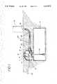
- FIG. 2is an elevational cross-section of a portion of the piping system of FIG. 1 showing in greater detail the connection of the flexible pipe with the pump body.
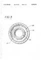
- FIG. 3is a cross-section taken along the line 3--3 of FIG. 2.
- FIG. 4is an elevational cross-section of a portion of the piping system of FIG. 1 showing in greater detail the connection of the flexible pipe with the fuel dispenser.
- FIG. 4shows an alternate embodiment of the embodiment of the invention shown in FIGS. 1 to 3.
- FIG. 5is a schematic elevational cross-section of the flexible piping run/manifold connection to other underground storage tank systems.
- FIG. 5shows another alternate embodiment of the invention shown in FIGS. 1 to 3 connecting a plurality of underground storage tank systems.
- FIGS. 6 and 7are each elevational views in cross-section showing in greater detail certain elements depicted schematically in FIG. 5.
- FIG. 1shows a conventional underground fuel tank 13 with a single manway 14 at grade level 28, equipped with a conventional containment chamber 12, which provides access to the pump 37 and the underground piping 19,22 connected to it.
- the underground tank 13is filled with fuel by opening the manway 14 and transferring fuel to tank 13 through the fill pipe 16.
- a pump 37is provided to pump fuel from the underground tank 13 through a primary pipe 22 to a fuel dispenser coupling 39 providing input to a fuel dispenser 35.
- the fuel dispenser 35may be a conventional service station gas pump.
- a secondary pipe 19jackets the primary pipe 22 and provides containment for any fuel that might leak out of primary pipe 22.
- the compression fittings 17, 18 for the secondary pipe 19 and the primary pipe 22are now accessible from the containment chamber 12.
- the compression fitting 17 for the secondary pipe 19is disconnected.
- the male-threaded coupling 20is next unscrewed from the female-tapped outer piping adaptor 15, and the male coupling 20 is forced away from the pump and outer piping adaptor, thereby exposing the compression fitting 18 connecting the primary pipe 22 with an inner pipe 23.
- the compression fitting 18can now be disconnected, thus disconnecting the primary pipe 22 and the secondary pipe 19 from the inner pipe 23 and the pump 37.
- the other ends of the primary pipe 22 and secondary pipe 19are similarly disconnected from the dispenser at or about grade level 28.
- the primary pipe 22can now be “fished” or pulled up and out from the outer secondary pipe 19 from grade level.
- the primary pipe 22 and the secondary pipe 19are accessible at both ends--below grade at the interface with the containment chamber, and at or about grade level at the interface with the fuel dispenser. Since the pipes 19, 22 are flexible, the pipe may be shipped to the field site where the tank is installed and cut at the job site to the desired length.
- the inner pipe 23is a forged or cast custom fitting comprising 2-inch outside diameter inner pipe connected to an outlet port of pump 37, below ground.
- the dispenser coupling 39has a corresponding fitting connected to the dispenser inlet port.
- the compression fitting 18clamps and firmly secures the primary pipe 22 to the inner pipe 23.
- the length of the inner pipe 23is typically two pipe diameters.
- the compression fitting 18may be substituted with a common hose clamp, strap or other fitting.
- the male coupling 20is a 4-inch outside diameter steel pipe adapter with external threads. It screws at one threaded end 55 into the outer piping adaptor 15.
- the flexible secondary pipe 19is desirably of 4-inch inside diameter hose piping. It slides over the free end of the male coupling 20.
- a compression fitting 17clamps and firmly secures the secondary pipe 19 to the male coupling 20.
- the secondary pipe 19is rendered inflexible as it is buried in the ground.
- the secondary pipe 19serves as a guide for the primary pipe 22 which slides into or is retractable from it.
- the inner pipe 23has a male thread 25 that screws into the outlet port of pump 37. (In some cases where the pump has a standard male connection, a standared pipe coupling may be necessary to connect the inner pipe.) Once the inner pipe 23 is screwed into the outlet port of the pump 37, the inner pipe 23 is fixed and is generally not removed.
- a boot 24is used to seal the entry of the secondary pipe, 19, where it enters the containment chamber 12 by being sealed to a sleeve 21 which is an integral part of the containment chamber 12.
- the leakageis contained inside the outer pipe 19, and will not escape into and flood the containment chamber 11. If a leak arises at the juncture of the inner pipe 23 and pump 37, or at either of the two compression fittings 17 or 18, the presence of boot 24 ensures that the leak is contained in the piping containment chamber 12 at 26 and does not overflow into the surrounding soil. The boot 24 also prevents leakage from the fill pipe 16 from escaping from the containment chamber 12 into the soil.
- the annular space between the coaxial primary pipe 22 and secondary pipe 19can be tested for leakage in the primary pipe 22 by locating one or more sensors 29 in the annular space 27 between the pipes 22 and 19.
- FIG. 4schematically illustrates a similar gas dispensing station with an alternate embodiment for securing the primary and secondary pipes to the pump at one end and the dispenser at the other end in an underground storage tank--dispenser piping system.
- a leak from the primary pipe 122which carries the product, will flow into the secondary pipe 119, which provides containment of the leak, from which it will drain by gravity to 126 in the leak containment chamber 112.
- the coupling 199secures the primary pipe 122 to the bottom of the shear valve 139 at the base of the dispenser 135.
- This coupling 199is substantially similar to the coupling 198 at the other end of the double piping system in the containment chamber 112.
- Couplings 198 and 199may be compression fittings similar to the compression fitting 18 shown in FIG. 2.
- the secondary pipe 119is connected directly to sleeves that protrude from the containment pan 138 at one end and the containment chamber 112 at the other end.
- the method of connectionmay be stainless steel straps or bands 157, applied in the field with a strap tightening tool. Alternatively, a compression fitting may be used. Access to the containment chamber 112 is provided through the manway 114.
- monitoring systemsare installed at the containment chamber 26 or 126 and necessary repairs can be performed without a "release" to the environment.
- Such monitoring systemsmay, for example, include one or more liquid sensors 129 at the bottom of the containment chamber 26, 126 connected to a conventional alarm system (not shown).
- the primary pipe 22 or 122can be replaced from above ground.
- the material of the primary pipe 22 or 122, and the secondary pipe 19 or 119 in the two depicted embodimentsis similar to the conventional ⁇ hose ⁇ construction, i.e. reinforced rubber or plastic material suitable for gasoline service.
- FIGS. 1, 2 & 4In such use there will be no: degradation of pipe material due to exposure to sunlight; deterioration of pipe material due to wear and tear which accompanies the frequent movement of the pipes as is now the case with conventional above-ground piping systems.
- the life expectancy of the underground piping system shown in FIG. 1, 2 or 4will exceed 10 years instead of the approximately 4-year average life expectancy of conventional above-ground pipe systems.
- a repeater containment chamber 212may be placed in the pipe run.
- the piping containment chamber 312, the primary and secondary piping system 222 and 219, the repeater containment chamber 212 and the fuel dispenser 235are schematically shown in FIG. 5.
- the use of repeater containment chamberswill be necessary in cases where the length of the primary and secondary piping system delivered to the jobsite is less than the distance between the piping containment chamber 312 and the fuel dispenser 235, or if multiple fuel storage tanks are utilized and interconnectors in the piping becomes necessary.
- the primary and secondary pipesmay consist of a plurality of pipe segments, each respective segment connected to one another so as to form a continuous primary pipe, or a continuous secondary pipe.
- a pump 337 having an input pipe 383 extending downwardly towards the bottom of storage tank (not shown)is within an underground containment 312.
- a primary pipe 382runs from containment 312 towards a dispenser 235.
- the pipeis not long enough to run all the way to dispenser 235 and instead terminates at an in-line coupling 384.
- the in-line coupling 384communicates with the primary pipe 382 on the one side and with another primary pipe 222 on the other side, joining them to form a continuous passage for fluid.
- Clamps 357secure pipes 382 and 222 to the coupling 384. Any leakage from either of the joints between the in-line coupling and pipe 382 or pipe 222 is contained within containment chamber 212.
- pipe 382should leak and need to be replaced, it can be accomplished without having to replace the entire piping between the pump 337 and the dispenser 235, and correspondingly so for pipe 222.
Landscapes
- Engineering & Computer Science (AREA)
- General Engineering & Computer Science (AREA)
- Mechanical Engineering (AREA)
- Physics & Mathematics (AREA)
- General Physics & Mathematics (AREA)
- Loading And Unloading Of Fuel Tanks Or Ships (AREA)
- Pipeline Systems (AREA)
Abstract
Description
Claims (48)
Priority Applications (13)
| Application Number | Priority Date | Filing Date | Title |
|---|---|---|---|
| US07/286,893US5553971A (en) | 1988-12-20 | 1988-12-20 | Double-containment underground piping system |
| US07/411,385US5098221A (en) | 1988-12-20 | 1989-09-22 | Flexible double-containment piping system for underground storage tanks |
| AT90902082TATE201757T1 (en) | 1988-12-20 | 1989-12-20 | FLEXIBLE, DOUBLE SECURED PIPE SYSTEM |
| DE68929300TDE68929300T2 (en) | 1988-12-20 | 1989-12-20 | FLEXIBLE, DOUBLE SECURED TUBE SYSTEM |
| JP50243090AJP2933094B2 (en) | 1988-12-20 | 1989-12-20 | Flexible double containment piping system for underground storage tanks. |
| AU49499/90AAU651312B2 (en) | 1988-12-20 | 1989-12-20 | Flexible double containment piping system |
| EP90902082AEP0464027B1 (en) | 1988-12-20 | 1989-12-20 | Flexible double-containment piping system |
| ES90902082TES2158837T3 (en) | 1988-12-20 | 1989-12-20 | FLEXIBLE SYSTEM OF DOUBLE CONTAINER PIPES. |
| PCT/US1989/005845WO1990007674A1 (en) | 1988-12-20 | 1989-12-20 | Flexible double-containment piping system |
| US08/469,651US5567083A (en) | 1988-12-20 | 1995-06-06 | Double-containment underground piping system |
| US08/469,652US5590981A (en) | 1988-12-20 | 1995-06-06 | Double-containment underground piping system |
| US08/778,474US5775842A (en) | 1988-12-20 | 1997-01-03 | Double containment under ground piping system |
| US09/085,747US6116817A (en) | 1988-12-20 | 1998-05-27 | Hydrocarbon fuel piping system with a flexible inner pipe and an outer pipe |
Applications Claiming Priority (1)
| Application Number | Priority Date | Filing Date | Title |
|---|---|---|---|
| US07/286,893US5553971A (en) | 1988-12-20 | 1988-12-20 | Double-containment underground piping system |
Related Child Applications (3)
| Application Number | Title | Priority Date | Filing Date |
|---|---|---|---|
| US07/411,385Continuation-In-PartUS5098221A (en) | 1988-12-20 | 1989-09-22 | Flexible double-containment piping system for underground storage tanks |
| US08/469,651ContinuationUS5567083A (en) | 1988-12-20 | 1995-06-06 | Double-containment underground piping system |
| US08/469,652ContinuationUS5590981A (en) | 1988-12-20 | 1995-06-06 | Double-containment underground piping system |
Publications (1)
| Publication Number | Publication Date |
|---|---|
| US5553971Atrue US5553971A (en) | 1996-09-10 |
Family
ID=23100622
Family Applications (5)
| Application Number | Title | Priority Date | Filing Date |
|---|---|---|---|
| US07/286,893Expired - LifetimeUS5553971A (en) | 1988-12-20 | 1988-12-20 | Double-containment underground piping system |
| US08/469,652Expired - LifetimeUS5590981A (en) | 1988-12-20 | 1995-06-06 | Double-containment underground piping system |
| US08/469,651Expired - LifetimeUS5567083A (en) | 1988-12-20 | 1995-06-06 | Double-containment underground piping system |
| US08/778,474Expired - LifetimeUS5775842A (en) | 1988-12-20 | 1997-01-03 | Double containment under ground piping system |
| US09/085,747Expired - LifetimeUS6116817A (en) | 1988-12-20 | 1998-05-27 | Hydrocarbon fuel piping system with a flexible inner pipe and an outer pipe |
Family Applications After (4)
| Application Number | Title | Priority Date | Filing Date |
|---|---|---|---|
| US08/469,652Expired - LifetimeUS5590981A (en) | 1988-12-20 | 1995-06-06 | Double-containment underground piping system |
| US08/469,651Expired - LifetimeUS5567083A (en) | 1988-12-20 | 1995-06-06 | Double-containment underground piping system |
| US08/778,474Expired - LifetimeUS5775842A (en) | 1988-12-20 | 1997-01-03 | Double containment under ground piping system |
| US09/085,747Expired - LifetimeUS6116817A (en) | 1988-12-20 | 1998-05-27 | Hydrocarbon fuel piping system with a flexible inner pipe and an outer pipe |
Country Status (1)
| Country | Link |
|---|---|
| US (5) | US5553971A (en) |
Cited By (22)
| Publication number | Priority date | Publication date | Assignee | Title |
|---|---|---|---|---|
| US5702129A (en)* | 1996-01-29 | 1997-12-30 | Donald Harrington | Riser assembly for underground pipe connections |
| US5775842A (en)* | 1988-12-20 | 1998-07-07 | Pisces By Opw, Inc. | Double containment under ground piping system |
| US5819975A (en)* | 1996-10-08 | 1998-10-13 | Dover Corp. | Dispenser sump |
| US5865216A (en) | 1995-11-08 | 1999-02-02 | Advanced Polymer Technology, Inc. | System for housing secondarily contained flexible piping |
| US5950860A (en)* | 1996-10-08 | 1999-09-14 | Dover Corp. | Adjustable length storage tank sumps |
| US6123365A (en)* | 1996-10-08 | 2000-09-26 | Delaware Capital Formation, Inc. | Structure for protecting a bulkhead fitting |
| US6197197B1 (en)* | 1998-04-23 | 2001-03-06 | Dialysis Systems, Inc. | Method for fluid delivery in a dialysis clinic |
| USRE37114E1 (en) | 1993-11-01 | 2001-03-27 | Advanced Polymer Technology, Inc. | Secondary containment flexible underground piping system |
| US6371154B1 (en) | 1999-09-17 | 2002-04-16 | Fisces By Opw, Inc. | Apparatus and system for containment |
| US20030230593A1 (en)* | 2002-06-18 | 2003-12-18 | Hutchinson Ray J. | Service station leak detection and recovery system |
| US20050169710A1 (en)* | 2003-12-11 | 2005-08-04 | Folkers Joie L. | Containment system |
| US20060191569A1 (en)* | 2005-02-18 | 2006-08-31 | Veeder-Root Company | Double-walled contained shear valve, particularly for fueling environments |
| US20060191568A1 (en)* | 2005-02-18 | 2006-08-31 | Veeder-Root Company | Double-walled contained shear valve, particularly for fueling environments |
| US20060249204A1 (en)* | 2005-02-18 | 2006-11-09 | Veeder-Root Company | Shear valve employing two-stage poppet valve, particularly for use in fueling environments |
| US20060260680A1 (en)* | 2005-04-26 | 2006-11-23 | Veeder-Root Company | Vacuum-actuated shear valve device, system, and method, particularly for use in service station environments |
| US20080011056A1 (en)* | 2006-07-14 | 2008-01-17 | Mauricio Pinto Spaolonzi | Flexible leak detection system and method for double carcass hose |
| US20080011057A1 (en)* | 2006-07-14 | 2008-01-17 | Mauricio Pinto Spaolonzi | Leak detection sensor system and method for double carcass hose |
| US7453367B2 (en) | 2005-12-12 | 2008-11-18 | Veyance Technologies, Inc. | Leak detection system and method for offshore hose lines |
| US20090223595A1 (en)* | 2008-03-04 | 2009-09-10 | Delaware Capital Formation, Inc. | Spill containment apparatus for storage tanks |
| CN104019374A (en)* | 2014-06-25 | 2014-09-03 | 济钢集团有限公司 | Leak-proof device for gas pipeline regulating valve |
| US9908692B2 (en) | 2015-05-06 | 2018-03-06 | ASFI Partners, L.P. | Multi-piece storage tank pad with separate connectors |
| US11041297B2 (en)* | 2019-11-15 | 2021-06-22 | Pre-Con Products | Water management system and methods |
Families Citing this family (33)
| Publication number | Priority date | Publication date | Assignee | Title |
|---|---|---|---|---|
| FR2735085B1 (en)* | 1995-06-12 | 1997-09-05 | Total Raffinage Distribution | PIPING SYSTEM FOR FILLING LIQUID FUEL FROM AN UNDERGROUND TANK AND FOR TRANSFERRING THIS FUEL TO A DISTRIBUTION STATION |
| FR2760064B1 (en) | 1997-02-25 | 2002-10-25 | Fluoroware Inc | THREADED CONNECTION AND DOUBLE CONTAINMENT SYSTEM |
| US6003537A (en)* | 1997-03-25 | 1999-12-21 | Bravo; Sergio M. | Removable penetration fittings using T-fitting and flexible pipe combination |
| US5955657A (en)* | 1997-03-25 | 1999-09-21 | Bravo; Sergio M. | Pipe layout with opposing incline |
| US6032699A (en)* | 1997-05-19 | 2000-03-07 | Furon Company | Fluid delivery pipe with leak detection |
| US6006773A (en)* | 1997-09-24 | 1999-12-28 | Bravo; Sergio M. | Installation method for pipe layout with opposing incline |
| US6052972A (en)* | 1997-12-19 | 2000-04-25 | Westinghouse Savannah River Company Llc | Portable containment sleever apparatus |
| US6085796A (en)* | 1998-07-31 | 2000-07-11 | Riga; Dennis J. | Dual containment hydraulic system |
| US6230735B1 (en)* | 1998-12-04 | 2001-05-15 | Sergio M. Bravo | Valve jacket |
| US6238137B1 (en)* | 1999-04-01 | 2001-05-29 | New Mexico Tech Research Foundation | Containment system for spills |
| BR0109105A (en)* | 2000-03-08 | 2002-12-03 | Petrotechnik Ltd | Improved containment system |
| US6536465B2 (en) | 2001-04-12 | 2003-03-25 | Clay And Bailey Manufacturing Company | Filling limitor for small, shallow liquid storage tanks |
| US20040020271A1 (en)* | 2002-07-31 | 2004-02-05 | Hutchinson Ray J. | Contaminant containment system in a fueling environment |
| US7011102B2 (en)* | 2002-08-23 | 2006-03-14 | Ameron International Corporation | Contained pipeline system with brine filled interstitial space and method for detecting leakage in same |
| US7500489B2 (en)* | 2002-08-23 | 2009-03-10 | Ameron International Corporation | Contained pipeline system with brine filled interstitial space and method for detecting leakage in same |
| US20040234338A1 (en)* | 2003-05-19 | 2004-11-25 | Monroe Thomas K. | Secondary containment monitoring system |
| US7069956B1 (en) | 2003-10-23 | 2006-07-04 | Mosier James W | Marina piping |
| US7229233B2 (en)* | 2004-03-10 | 2007-06-12 | Xerxes Corporation | Double walled containment sumps |
| US20060185729A1 (en)* | 2005-02-18 | 2006-08-24 | Ingram Thomas L | Double-walled flexible dispenser sump connection system |
| US7104727B1 (en)* | 2005-02-22 | 2006-09-12 | Webb Michael C | Piping system with transition coupling |
| US20140124070A1 (en)* | 2006-03-08 | 2014-05-08 | Quality Steel Corporation | Underground storage tank |
| US8104327B1 (en)* | 2006-09-27 | 2012-01-31 | C.G.R.S. Inc. | Leak detection method for a primary containment system |
| US7461541B2 (en)* | 2006-09-27 | 2008-12-09 | C.G.R.S., Inc | Leak detection method for a primary containment system |
| EP2664372A1 (en) | 2006-10-06 | 2013-11-20 | Donaldson Company, Inc. | Air cleaner, replaceable filter cartridges, and methods |
| EP2372222B1 (en)* | 2010-03-29 | 2014-02-26 | MT-Energie GmbH | Device for guiding fluids involved in the operation of biogas facilities, sewage treatment facilities or agricultural facilities |
| US9958096B2 (en) | 2011-09-28 | 2018-05-01 | Franklin Fueling Systems, Llc | Split test boot |
| FR3028303B1 (en) | 2014-11-12 | 2016-12-30 | Commissariat Energie Atomique | DEVICE FOR FLUIDIC CONNECTION OF A DOUBLE ENVELOPE FLUID LINE COMPRISING FIRST AND SECOND FLUID CONNECTORS |
| US11578710B2 (en) | 2019-05-02 | 2023-02-14 | Kerr Machine Co. | Fracturing pump with in-line fluid end |
| US11965503B2 (en) | 2019-05-14 | 2024-04-23 | Halliburton Energy Services, Inc. | Flexible manifold for reciprocating pump |
| US11261863B2 (en) | 2019-05-14 | 2022-03-01 | Halliburton Energy Services, Inc. | Flexible manifold for reciprocating pump |
| US10808851B1 (en) | 2019-06-10 | 2020-10-20 | Halliburton Energy Services, Inc. | Multi-material frac valve poppet |
| US10677380B1 (en)* | 2019-07-26 | 2020-06-09 | Halliburton Energy Services, Inc. | Fail safe suction hose for significantly moving suction port |
| WO2023034190A1 (en) | 2021-08-30 | 2023-03-09 | ND Energy Services Management, Inc. | Water line junction device |
Citations (60)
| Publication number | Priority date | Publication date | Assignee | Title |
|---|---|---|---|---|
| US216286A (en)* | 1879-06-10 | Improvement in apparatus for supplying steam for heating and other purposes | ||
| US244752A (en)* | 1881-07-26 | And josiah s | ||
| US272833A (en)* | 1883-02-20 | System of laying subterranean lines of electric wires | ||
| US286938A (en)* | 1883-10-16 | Conduit for electric wires | ||
| US291715A (en)* | 1884-01-08 | Underground electrical conductor | ||
| US430010A (en)* | 1890-06-10 | Underground electric conduit | ||
| US470946A (en)* | 1892-03-15 | munsie | ||
| US648128A (en)* | 1899-06-14 | 1900-04-24 | David Young Kinniburgh | System for laying supply-pipes. |
| US745351A (en)* | 1902-07-03 | 1903-12-01 | Oliver T Hungerford | Water-supply system. |
| US997434A (en)* | 1909-05-15 | 1911-07-11 | Eugene L Barnes | Underground steam-distributing system. |
| US1188446A (en)* | 1915-04-22 | 1916-06-27 | Johnathan Haines | Gasolene-supply apparatus. |
| US1375363A (en)* | 1919-08-18 | 1921-04-19 | Frederick S Cary | Liquid-dispensing device |
| US1986789A (en)* | 1933-07-19 | 1935-01-08 | Okonite Callender Cable Co Inc | Electric power cable system for the underground transmission of electrical energy |
| US2050968A (en)* | 1933-03-25 | 1936-08-11 | Ric Wil Company | Conduit construction |
| US2093114A (en)* | 1934-09-03 | 1937-09-14 | Gen Cable Corp | Electric cable and method of installation |
| US2113204A (en)* | 1938-04-05 | Means for repairing gas ones | ||
| US2129924A (en)* | 1934-06-15 | 1938-09-13 | Arch H Galbraith | Underground tank system |
| US2306331A (en)* | 1940-05-01 | 1942-12-22 | William B Elmer | Method and apparatus for protecting cables |
| US2325565A (en)* | 1941-01-10 | 1943-07-27 | Cons Edison Co New York Inc | Installation of underground ducts |
| US2336150A (en)* | 1940-06-24 | 1943-12-07 | Dayton Pump & Mfg Co | Airport gasoline dispensing system |
| US2347912A (en)* | 1941-03-11 | 1944-05-02 | Detroit Edison Co | Method of installing electric cables |
| US2487939A (en)* | 1948-11-16 | 1949-11-15 | Norton Mcmurray Mfg Company | House service pipe connection |
| US2507597A (en)* | 1945-01-22 | 1950-05-16 | Erie Meter Systems Inc | Airport fueling system |
| US2546348A (en)* | 1947-08-19 | 1951-03-27 | Dresser Ind | Service head fitting |
| US2956586A (en)* | 1959-09-03 | 1960-10-18 | Gen Motors Corp | Hose arrangement |
| US3221758A (en)* | 1962-03-22 | 1965-12-07 | Omco Inc | Method and apparatus for sealing a pipe line |
| US3531264A (en)* | 1967-10-03 | 1970-09-29 | Frank J Greipel | Safety leak detector |
| US3543377A (en)* | 1968-12-30 | 1970-12-01 | Raymond Muir Bremner | Vibratory towing head |
| US3559408A (en)* | 1968-09-26 | 1971-02-02 | Mar M Earnhart | Spring development system |
| US3672103A (en)* | 1969-12-31 | 1972-06-27 | City Of Fort Collins | Modular utility vault |
| US3688801A (en)* | 1971-03-09 | 1972-09-05 | Carl H Rohrer | Method for replacing gas mains |
| US3799440A (en)* | 1972-03-02 | 1974-03-26 | American Aero Ind | Safety apparatus |
| US3841671A (en)* | 1973-10-30 | 1974-10-15 | Gen Motors Corp | Coaxial fluid lines with plug-in connector assemblies |
| US3995472A (en)* | 1975-06-26 | 1976-12-07 | Murgor Electric Company, Inc. | Detector system |
| US4009739A (en)* | 1975-09-02 | 1977-03-01 | Weatherford Danny J | Gasoline and vapor return hose system for delivery truck |
| US4010581A (en)* | 1975-07-17 | 1977-03-08 | Keturi Raymond C | Cored slab building construction |
| US4020641A (en)* | 1975-12-22 | 1977-05-03 | Kabushiki Kaisha Komatsu Seisakusho | Method of laying pipes in the ground |
| US4062376A (en)* | 1975-09-05 | 1977-12-13 | Mcgrath Robert L | Service connection between a main and a meter in a building and method of and equipment for installing the same |
| US4110947A (en)* | 1977-12-09 | 1978-09-05 | Murgor Electric Company, Inc. | Storage tank installation |
| US4149568A (en)* | 1977-12-07 | 1979-04-17 | Caterpillar Tractor Co. | Double walled fuel line |
| US4309128A (en)* | 1979-11-26 | 1982-01-05 | Williams Richard Lee | Method and apparatus for removing deflection from plastic pipes |
| US4318835A (en)* | 1980-07-21 | 1982-03-09 | Hayward Baker Company | Magnesium diacrylate, polyol monoacrylate grouting composition and method for grouting joints and/or cracks in sewer conduits therewith |
| US4449853A (en)* | 1983-04-11 | 1984-05-22 | Mennella Robert J | Flexible sleeve elbow for gas service lines |
| US4561292A (en)* | 1984-01-19 | 1985-12-31 | Owens-Corning Fiberglas Corporation | Double-wall underground container for storing liquids and leak detecting means therefor |
| US4565351A (en)* | 1984-06-28 | 1986-01-21 | Arnco Corporation | Method for installing cable using an inner duct |
| US4612744A (en)* | 1981-08-07 | 1986-09-23 | Shamash Jack E | Method, components, and system for assembling buildings |
| US4639164A (en)* | 1985-05-06 | 1987-01-27 | Owens-Corning Fiberglas Corporation | Underground tank sump and piping system |
| US4643460A (en)* | 1985-02-06 | 1987-02-17 | Construction Forms, Inc. | High pressure concrete line coupling clamp with limit adjust apparatus |
| US4644780A (en)* | 1983-10-19 | 1987-02-24 | Westinghouse Electric Corp. | Self-supporting pipe rupture and whip restraint |
| US4667505A (en)* | 1985-05-08 | 1987-05-26 | Sharp Bruce R | Split fittings and pipeline systems using same |
| US4678370A (en)* | 1984-12-04 | 1987-07-07 | Danby Pty. Ltd. | Sewer renovation system |
| US4682911A (en)* | 1984-03-06 | 1987-07-28 | Mpc Containment Systems, Ltd. | Secondary containment systems especially well suited for hydrocarbon storage and delivery systems |
| US4685831A (en)* | 1985-09-30 | 1987-08-11 | Pierre L. LaBarge, Jr. | Apparatus and methods for removing underground cable |
| US4739648A (en)* | 1985-12-09 | 1988-04-26 | Horner John A | Methods and system for determining leaks in underground liquid storage tanks and the like |
| US4787772A (en)* | 1987-06-26 | 1988-11-29 | Eljen Corporation | Device for detecting leaks in underground fluid tanks |
| US4796669A (en)* | 1981-07-10 | 1989-01-10 | Duratron Systems Limited | Product for relining sewers and water pipes |
| US4796676A (en)* | 1987-06-05 | 1989-01-10 | Hendershot John A | Fluid storage tank system |
| US4805444A (en)* | 1987-10-01 | 1989-02-21 | Webb Michael C | Secondary containment system |
| US4874268A (en)* | 1987-11-18 | 1989-10-17 | Kabushiki Kaisha Iseki Kaihatsu Koki | Method and apparatus for building pipeline and shield tunnelling machine |
| WO1990004157A1 (en)* | 1988-10-06 | 1990-04-19 | Total Containment | Secondary containment system using flexible piping |
Family Cites Families (36)
| Publication number | Priority date | Publication date | Assignee | Title |
|---|---|---|---|---|
| US2268263A (en)* | 1941-05-15 | 1941-12-30 | Dresser Mfg Company | Pipe fitting |
| GB1039515A (en)* | 1962-07-24 | 1966-08-17 | Power Aux Ies Ltd | Improvements in or relating to flexible pressure tubes and ducts |
| US3379027A (en)* | 1965-03-30 | 1968-04-23 | Exxon Research Engineering Co | Roller-supported lng pipeline |
| BE754140A (en)* | 1969-09-02 | 1970-12-31 | Wittgenstein Gerard F | SAFETY INSTALLATION PROHIBITING POLLUTION BY PIPELINES |
| DE7147848U (en)* | 1971-12-20 | 1972-08-24 | Gutehoffnungshuette Ag | LEAK CONTROL DEVICE WITH TRANSFER OF LIQUID OR GAS MEDIA |
| BE791014A (en)* | 1971-12-27 | 1973-03-01 | Kabel Metallwerke Ghh | TUBULAR STRUCTURE |
| DE7417030U (en)* | 1974-05-15 | 1974-10-03 | Kabel Und Metallwerke Gutehoffnungshuette Ag | FLEXIBLE PIPE FOR CONVEYING LIQUID OR GAS MEDIA |
| JPS513055A (en)* | 1974-06-26 | 1976-01-12 | Morio Sumimoto | |
| US4159027A (en)* | 1975-02-27 | 1979-06-26 | Caillet Pierre G | Flexible hose for connecting sanitary appliances |
| US3980112A (en)* | 1975-03-21 | 1976-09-14 | Dayco Corporation | Conduit assembly for conveying volatile fluids |
| US4094536A (en)* | 1976-12-20 | 1978-06-13 | Continental Industries, Inc. | Meter riser |
| US4127286A (en)* | 1977-10-11 | 1978-11-28 | Corning Glass Works | Concentric pipe coupling |
| DE2826659C2 (en)* | 1978-06-19 | 1985-09-12 | Gewerkschaft Eisenhütte Westfalia, 4670 Lünen | Jacketed high pressure hose for use in mining operations |
| US4274549A (en)* | 1979-09-27 | 1981-06-23 | The Goodyear Tire & Rubber Company | Apparatus for fuel vapor recovery |
| JPS5711800A (en)* | 1980-06-26 | 1982-01-21 | Hitachi Metals Ltd | Separating device for removed water |
| US4315408A (en)* | 1980-12-18 | 1982-02-16 | Amtel, Inc. | Offshore liquified gas transfer system |
| US4411290A (en)* | 1981-06-15 | 1983-10-25 | Chevron Research Company | Bottom loading arm for bulk liquid carriers |
| JPS57146126A (en)* | 1981-08-10 | 1982-09-09 | Tokyo Tatsuno Co Ltd | Oil leakage detecting device |
| US4457349A (en)* | 1982-01-19 | 1984-07-03 | Chevron Research Company | Volatile hydrocarbon recovery system for tank truck unloading headers |
| US4519634A (en)* | 1982-12-22 | 1985-05-28 | Hand James D | Transition pipe fitting |
| US4912966A (en)* | 1985-06-17 | 1990-04-03 | Sharp Bruce R | Total containment means for storage tank systems |
| US4702645A (en)* | 1984-08-27 | 1987-10-27 | Press-Seal Gasket Corporation | Slipline adjustable manhole seal |
| US4619555A (en)* | 1984-08-27 | 1986-10-28 | Press-Seal Gasket Corporation | Slipline adjustable manhole seal |
| US4778310A (en)* | 1986-11-14 | 1988-10-18 | Mpc Containment Systems, Ltd. | Means for installing membranes in containment pits for tanks storing liquids |
| EP0207015A3 (en)* | 1985-06-18 | 1990-05-02 | DITTA PACETTI ANTONIO di Silvano & Andrea Pacetti | Ventilated collector for a gas distribution network for domestic or other use |
| JPS6223000A (en)* | 1985-07-23 | 1987-01-31 | 旭化成株式会社 | Loading device for blasting inclusions |
| JPS62200630A (en)* | 1986-02-28 | 1987-09-04 | 株式会社山武 | Fiber optic photoelectric switch |
| US5005613A (en)* | 1986-09-26 | 1991-04-09 | The Goodyear Tire & Rubber Company | Light weight flexible coaxial vapor recovery hose |
| JPH0641173B2 (en)* | 1986-10-16 | 1994-06-01 | ハンス・ミユラ− | How to repair a conduit laid underground |
| US4886304A (en)* | 1987-02-18 | 1989-12-12 | Victaulic Company Of America | Abrasive grip pipe coupling |
| US5042537A (en)* | 1987-09-18 | 1991-08-27 | Dayco Products, Inc. | Hose assembly and method of making the same |
| US4932257A (en)* | 1987-10-01 | 1990-06-12 | Webb Michael C | Double wall piping system |
| US5553971A (en)* | 1988-12-20 | 1996-09-10 | Intelpro Corporation | Double-containment underground piping system |
| US5098221A (en)* | 1988-12-20 | 1992-03-24 | Osborne Keith J | Flexible double-containment piping system for underground storage tanks |
| US4971477A (en)* | 1988-12-22 | 1990-11-20 | Total Containment, Inc. | Secondary contained fluid supply system |
| US4991626A (en)* | 1989-10-05 | 1991-02-12 | Dayco Products, Inc. | Breakaway coupling, conduit system utilizing the coupling and methods of making the same |
- 1988
- 1988-12-20USUS07/286,893patent/US5553971A/ennot_activeExpired - Lifetime
- 1995
- 1995-06-06USUS08/469,652patent/US5590981A/ennot_activeExpired - Lifetime
- 1995-06-06USUS08/469,651patent/US5567083A/ennot_activeExpired - Lifetime
- 1997
- 1997-01-03USUS08/778,474patent/US5775842A/ennot_activeExpired - Lifetime
- 1998
- 1998-05-27USUS09/085,747patent/US6116817A/ennot_activeExpired - Lifetime
Patent Citations (61)
| Publication number | Priority date | Publication date | Assignee | Title |
|---|---|---|---|---|
| US216286A (en)* | 1879-06-10 | Improvement in apparatus for supplying steam for heating and other purposes | ||
| US244752A (en)* | 1881-07-26 | And josiah s | ||
| US272833A (en)* | 1883-02-20 | System of laying subterranean lines of electric wires | ||
| US286938A (en)* | 1883-10-16 | Conduit for electric wires | ||
| US291715A (en)* | 1884-01-08 | Underground electrical conductor | ||
| US430010A (en)* | 1890-06-10 | Underground electric conduit | ||
| US470946A (en)* | 1892-03-15 | munsie | ||
| US2113204A (en)* | 1938-04-05 | Means for repairing gas ones | ||
| US648128A (en)* | 1899-06-14 | 1900-04-24 | David Young Kinniburgh | System for laying supply-pipes. |
| US745351A (en)* | 1902-07-03 | 1903-12-01 | Oliver T Hungerford | Water-supply system. |
| US997434A (en)* | 1909-05-15 | 1911-07-11 | Eugene L Barnes | Underground steam-distributing system. |
| US1188446A (en)* | 1915-04-22 | 1916-06-27 | Johnathan Haines | Gasolene-supply apparatus. |
| US1375363A (en)* | 1919-08-18 | 1921-04-19 | Frederick S Cary | Liquid-dispensing device |
| US2050968A (en)* | 1933-03-25 | 1936-08-11 | Ric Wil Company | Conduit construction |
| US1986789A (en)* | 1933-07-19 | 1935-01-08 | Okonite Callender Cable Co Inc | Electric power cable system for the underground transmission of electrical energy |
| US2129924A (en)* | 1934-06-15 | 1938-09-13 | Arch H Galbraith | Underground tank system |
| US2093114A (en)* | 1934-09-03 | 1937-09-14 | Gen Cable Corp | Electric cable and method of installation |
| US2306331A (en)* | 1940-05-01 | 1942-12-22 | William B Elmer | Method and apparatus for protecting cables |
| US2336150A (en)* | 1940-06-24 | 1943-12-07 | Dayton Pump & Mfg Co | Airport gasoline dispensing system |
| US2325565A (en)* | 1941-01-10 | 1943-07-27 | Cons Edison Co New York Inc | Installation of underground ducts |
| US2347912A (en)* | 1941-03-11 | 1944-05-02 | Detroit Edison Co | Method of installing electric cables |
| US2507597A (en)* | 1945-01-22 | 1950-05-16 | Erie Meter Systems Inc | Airport fueling system |
| US2546348A (en)* | 1947-08-19 | 1951-03-27 | Dresser Ind | Service head fitting |
| US2487939A (en)* | 1948-11-16 | 1949-11-15 | Norton Mcmurray Mfg Company | House service pipe connection |
| US2956586A (en)* | 1959-09-03 | 1960-10-18 | Gen Motors Corp | Hose arrangement |
| US3221758A (en)* | 1962-03-22 | 1965-12-07 | Omco Inc | Method and apparatus for sealing a pipe line |
| US3531264A (en)* | 1967-10-03 | 1970-09-29 | Frank J Greipel | Safety leak detector |
| US3559408A (en)* | 1968-09-26 | 1971-02-02 | Mar M Earnhart | Spring development system |
| US3543377A (en)* | 1968-12-30 | 1970-12-01 | Raymond Muir Bremner | Vibratory towing head |
| US3672103A (en)* | 1969-12-31 | 1972-06-27 | City Of Fort Collins | Modular utility vault |
| US3688801A (en)* | 1971-03-09 | 1972-09-05 | Carl H Rohrer | Method for replacing gas mains |
| US3799440A (en)* | 1972-03-02 | 1974-03-26 | American Aero Ind | Safety apparatus |
| US3841671A (en)* | 1973-10-30 | 1974-10-15 | Gen Motors Corp | Coaxial fluid lines with plug-in connector assemblies |
| US3995472A (en)* | 1975-06-26 | 1976-12-07 | Murgor Electric Company, Inc. | Detector system |
| US4010581A (en)* | 1975-07-17 | 1977-03-08 | Keturi Raymond C | Cored slab building construction |
| US4009739A (en)* | 1975-09-02 | 1977-03-01 | Weatherford Danny J | Gasoline and vapor return hose system for delivery truck |
| US4062376A (en)* | 1975-09-05 | 1977-12-13 | Mcgrath Robert L | Service connection between a main and a meter in a building and method of and equipment for installing the same |
| US4020641A (en)* | 1975-12-22 | 1977-05-03 | Kabushiki Kaisha Komatsu Seisakusho | Method of laying pipes in the ground |
| US4149568A (en)* | 1977-12-07 | 1979-04-17 | Caterpillar Tractor Co. | Double walled fuel line |
| US4110947A (en)* | 1977-12-09 | 1978-09-05 | Murgor Electric Company, Inc. | Storage tank installation |
| US4309128A (en)* | 1979-11-26 | 1982-01-05 | Williams Richard Lee | Method and apparatus for removing deflection from plastic pipes |
| US4318835A (en)* | 1980-07-21 | 1982-03-09 | Hayward Baker Company | Magnesium diacrylate, polyol monoacrylate grouting composition and method for grouting joints and/or cracks in sewer conduits therewith |
| US4796669A (en)* | 1981-07-10 | 1989-01-10 | Duratron Systems Limited | Product for relining sewers and water pipes |
| US4612744A (en)* | 1981-08-07 | 1986-09-23 | Shamash Jack E | Method, components, and system for assembling buildings |
| US4449853A (en)* | 1983-04-11 | 1984-05-22 | Mennella Robert J | Flexible sleeve elbow for gas service lines |
| US4644780A (en)* | 1983-10-19 | 1987-02-24 | Westinghouse Electric Corp. | Self-supporting pipe rupture and whip restraint |
| US4561292A (en)* | 1984-01-19 | 1985-12-31 | Owens-Corning Fiberglas Corporation | Double-wall underground container for storing liquids and leak detecting means therefor |
| US4682911A (en)* | 1984-03-06 | 1987-07-28 | Mpc Containment Systems, Ltd. | Secondary containment systems especially well suited for hydrocarbon storage and delivery systems |
| US4565351A (en)* | 1984-06-28 | 1986-01-21 | Arnco Corporation | Method for installing cable using an inner duct |
| US4565351B1 (en)* | 1984-06-28 | 1992-12-01 | Arnco Corp | |
| US4678370A (en)* | 1984-12-04 | 1987-07-07 | Danby Pty. Ltd. | Sewer renovation system |
| US4643460A (en)* | 1985-02-06 | 1987-02-17 | Construction Forms, Inc. | High pressure concrete line coupling clamp with limit adjust apparatus |
| US4639164A (en)* | 1985-05-06 | 1987-01-27 | Owens-Corning Fiberglas Corporation | Underground tank sump and piping system |
| US4667505A (en)* | 1985-05-08 | 1987-05-26 | Sharp Bruce R | Split fittings and pipeline systems using same |
| US4685831A (en)* | 1985-09-30 | 1987-08-11 | Pierre L. LaBarge, Jr. | Apparatus and methods for removing underground cable |
| US4739648A (en)* | 1985-12-09 | 1988-04-26 | Horner John A | Methods and system for determining leaks in underground liquid storage tanks and the like |
| US4796676A (en)* | 1987-06-05 | 1989-01-10 | Hendershot John A | Fluid storage tank system |
| US4787772A (en)* | 1987-06-26 | 1988-11-29 | Eljen Corporation | Device for detecting leaks in underground fluid tanks |
| US4805444A (en)* | 1987-10-01 | 1989-02-21 | Webb Michael C | Secondary containment system |
| US4874268A (en)* | 1987-11-18 | 1989-10-17 | Kabushiki Kaisha Iseki Kaihatsu Koki | Method and apparatus for building pipeline and shield tunnelling machine |
| WO1990004157A1 (en)* | 1988-10-06 | 1990-04-19 | Total Containment | Secondary containment system using flexible piping |
Cited By (41)
| Publication number | Priority date | Publication date | Assignee | Title |
|---|---|---|---|---|
| US5775842A (en)* | 1988-12-20 | 1998-07-07 | Pisces By Opw, Inc. | Double containment under ground piping system |
| US6116817A (en)* | 1988-12-20 | 2000-09-12 | Pisces By Opw, Inc. | Hydrocarbon fuel piping system with a flexible inner pipe and an outer pipe |
| USRE37114E1 (en) | 1993-11-01 | 2001-03-27 | Advanced Polymer Technology, Inc. | Secondary containment flexible underground piping system |
| US5865216A (en) | 1995-11-08 | 1999-02-02 | Advanced Polymer Technology, Inc. | System for housing secondarily contained flexible piping |
| US5702129A (en)* | 1996-01-29 | 1997-12-30 | Donald Harrington | Riser assembly for underground pipe connections |
| US5819975A (en)* | 1996-10-08 | 1998-10-13 | Dover Corp. | Dispenser sump |
| US5950860A (en)* | 1996-10-08 | 1999-09-14 | Dover Corp. | Adjustable length storage tank sumps |
| US6123365A (en)* | 1996-10-08 | 2000-09-26 | Delaware Capital Formation, Inc. | Structure for protecting a bulkhead fitting |
| US6224115B1 (en) | 1996-10-08 | 2001-05-01 | Delaware Capital Formation, Inc. | Bulkhead fitting for underground sump |
| US6506301B1 (en) | 1998-04-23 | 2003-01-14 | Dialysis Systems, Inc. | Apparatus for fluid delivery in a dialysis clinic |
| US6197197B1 (en)* | 1998-04-23 | 2001-03-06 | Dialysis Systems, Inc. | Method for fluid delivery in a dialysis clinic |
| US6371154B1 (en) | 1999-09-17 | 2002-04-16 | Fisces By Opw, Inc. | Apparatus and system for containment |
| US20030230593A1 (en)* | 2002-06-18 | 2003-12-18 | Hutchinson Ray J. | Service station leak detection and recovery system |
| US20030230592A1 (en)* | 2002-06-18 | 2003-12-18 | Hutchinson Ray J. | Service station leak detection and recovery system |
| US20050034508A1 (en)* | 2002-06-18 | 2005-02-17 | Hutchinson Ray J. | Service station leak detection and recovery system |
| US6935161B2 (en) | 2002-06-18 | 2005-08-30 | Gilbarco Inc. | Service station leak detection and recovery system |
| US20050205157A1 (en)* | 2002-06-18 | 2005-09-22 | Gilbarco Inc. | Service station leak detection and recovery system |
| US6962269B2 (en) | 2002-06-18 | 2005-11-08 | Gilbarco Inc. | Service station leak detection and recovery system |
| US6974054B2 (en) | 2002-06-18 | 2005-12-13 | Gilbarco Inc. | Service station leak detection with recovery system |
| US7455194B2 (en) | 2002-06-18 | 2008-11-25 | Gilbarco Inc. | Service station leak detection and recovery system |
| US20050169710A1 (en)* | 2003-12-11 | 2005-08-04 | Folkers Joie L. | Containment system |
| US20060191569A1 (en)* | 2005-02-18 | 2006-08-31 | Veeder-Root Company | Double-walled contained shear valve, particularly for fueling environments |
| US7753067B2 (en) | 2005-02-18 | 2010-07-13 | Veeder-Root Company | Shear valve employing two-stage poppet valve, particularly for use in fueling environments |
| US8387646B2 (en) | 2005-02-18 | 2013-03-05 | Veeder-Root Company | Double-walled contained shear valve, particularly for fueling environments |
| US20060249204A1 (en)* | 2005-02-18 | 2006-11-09 | Veeder-Root Company | Shear valve employing two-stage poppet valve, particularly for use in fueling environments |
| US20060191568A1 (en)* | 2005-02-18 | 2006-08-31 | Veeder-Root Company | Double-walled contained shear valve, particularly for fueling environments |
| US8096315B2 (en) | 2005-02-18 | 2012-01-17 | Veeder-Root Company | Double-walled contained shear valve, particularly for fueling environments |
| US7681583B2 (en) | 2005-02-18 | 2010-03-23 | Veeder-Root Company | Double-walled contained shear valve, particularly for fueling environments |
| US20060260680A1 (en)* | 2005-04-26 | 2006-11-23 | Veeder-Root Company | Vacuum-actuated shear valve device, system, and method, particularly for use in service station environments |
| US8291928B2 (en) | 2005-04-26 | 2012-10-23 | Veeder-Root Company | Vacuum-actuated shear valve device, system, and method, particularly for use in service station environments |
| US7946309B2 (en) | 2005-04-26 | 2011-05-24 | Veeder-Root Company | Vacuum-actuated shear valve device, system, and method, particularly for use in service station environments |
| US7453367B2 (en) | 2005-12-12 | 2008-11-18 | Veyance Technologies, Inc. | Leak detection system and method for offshore hose lines |
| US7387012B2 (en) | 2006-07-14 | 2008-06-17 | Veyance Technologies, Inc. | Leak detection sensor system and method for double carcass hose |
| US7509841B2 (en) | 2006-07-14 | 2009-03-31 | Veyance Technologies, Inc. | Flexible leak detection system and method for double carcass hose |
| US20080011057A1 (en)* | 2006-07-14 | 2008-01-17 | Mauricio Pinto Spaolonzi | Leak detection sensor system and method for double carcass hose |
| US20080011056A1 (en)* | 2006-07-14 | 2008-01-17 | Mauricio Pinto Spaolonzi | Flexible leak detection system and method for double carcass hose |
| US20090223595A1 (en)* | 2008-03-04 | 2009-09-10 | Delaware Capital Formation, Inc. | Spill containment apparatus for storage tanks |
| US8622097B2 (en) | 2008-03-04 | 2014-01-07 | Delaware Capital Formation, Inc. | Spill containment apparatus for storage tanks |
| CN104019374A (en)* | 2014-06-25 | 2014-09-03 | 济钢集团有限公司 | Leak-proof device for gas pipeline regulating valve |
| US9908692B2 (en) | 2015-05-06 | 2018-03-06 | ASFI Partners, L.P. | Multi-piece storage tank pad with separate connectors |
| US11041297B2 (en)* | 2019-11-15 | 2021-06-22 | Pre-Con Products | Water management system and methods |
Also Published As
| Publication number | Publication date |
|---|---|
| US5567083A (en) | 1996-10-22 |
| US5590981A (en) | 1997-01-07 |
| US6116817A (en) | 2000-09-12 |
| US5775842A (en) | 1998-07-07 |
Similar Documents
| Publication | Publication Date | Title |
|---|---|---|
| US5553971A (en) | Double-containment underground piping system | |
| AU651312B2 (en) | Flexible double containment piping system | |
| US4971477A (en) | Secondary contained fluid supply system | |
| US5713607A (en) | Pipe coupling assembly, system and method | |
| AU696049B2 (en) | Pipe coupling assembly, system and method | |
| US6029505A (en) | Connecting device for pipe assemblies | |
| EP0632871B1 (en) | Environmentally safe underground piping system | |
| US4939923A (en) | Method of retrofitting a primary pipeline system with a semi-rigid pipeline | |
| US4870856A (en) | Split fittings useful in forming a secondary semi-rigid pipeline over primary pipelines | |
| EP0592639A1 (en) | Secondary containment flexible underground piping system | |
| JP2933094B2 (en) | Flexible double containment piping system for underground storage tanks. | |
| US20050169710A1 (en) | Containment system |
Legal Events
| Date | Code | Title | Description |
|---|---|---|---|
| AS | Assignment | Owner name:INTELPRO CORPORATION, ILLINOIS Free format text:ASSIGNMENT OF ASSIGNORS INTEREST.;ASSIGNOR:OSBORNE, KEITH J.;REEL/FRAME:005939/0033 Effective date:19911113 | |
| STCF | Information on status: patent grant | Free format text:PATENTED CASE | |
| AS | Assignment | Owner name:OPW/BUFFALO ACQUISITION, INC. (MERGED INTO), PISCE Free format text:ASSIGNMENT OF ASSIGNORS INTEREST;ASSIGNOR:INTELPRO CORPORATION;REEL/FRAME:008967/0363 Effective date:19970522 Owner name:PISCES BY OPW, INC., OHIO Free format text:CHANGE OF NAME;ASSIGNOR:OPW/BUFFALO ACQUISITION, INC.;REEL/FRAME:008967/0342 Effective date:19970617 | |
| FEPP | Fee payment procedure | Free format text:PAYOR NUMBER ASSIGNED (ORIGINAL EVENT CODE: ASPN); ENTITY STATUS OF PATENT OWNER: LARGE ENTITY | |
| FEPP | Fee payment procedure | Free format text:PAT HLDR NO LONGER CLAIMS SMALL ENT STAT AS SMALL BUSINESS (ORIGINAL EVENT CODE: LSM2); ENTITY STATUS OF PATENT OWNER: LARGE ENTITY | |
| FPAY | Fee payment | Year of fee payment:4 | |
| FPAY | Fee payment | Year of fee payment:8 | |
| FPAY | Fee payment | Year of fee payment:12 | |
| REMI | Maintenance fee reminder mailed | ||
| RR | Request for reexamination filed | Effective date:20090908 | |
| B1 | Reexamination certificate first reexamination | Free format text:THE PATENTABILITY OF CLAIMS 1-3 AND 5 IS CONFIRMED. CLAIMS 4, 7, 34, 41, 43, 47 AND 48 ARE CANCELLED. CLAIMS 6, 8, 28, 32, 33 AND 35-37 ARE DETERMINED TO BE PATENTABLE AS AMENDED. CLAIMS 10-16, 19-22, 24-27, 29 AND 38-40, DEPENDENT ON AN AMENDED CLAIM, ARE DETERMINED TO BE PATENTABLE. NEW CLAIMS 49-55 ARE ADDED AND DETERMINED TO BE PATENTABLE. CLAIMS 9, 17, 18, 23, 30, 31, 42 AND 44-46 WERE NOT REEXAMINED. |