US5553541A - Gapless tubular printing blanket - Google Patents
Gapless tubular printing blanketDownload PDFInfo
- Publication number
- US5553541A US5553541AUS08/129,551US12955193AUS5553541AUS 5553541 AUS5553541 AUS 5553541AUS 12955193 AUS12955193 AUS 12955193AUS 5553541 AUS5553541 AUS 5553541A
- Authority
- US
- United States
- Prior art keywords
- printing
- layer
- blanket
- compressible
- tubular
- Prior art date
- Legal status (The legal status is an assumption and is not a legal conclusion. Google has not performed a legal analysis and makes no representation as to the accuracy of the status listed.)
- Expired - Lifetime
Links
- 238000007639printingMethods0.000titleclaimsabstractdescription153
- 239000000463materialSubstances0.000claimsabstractdescription19
- 239000013536elastomeric materialSubstances0.000abstractdescription31
- 239000004005microsphereSubstances0.000abstractdescription19
- 238000000034methodMethods0.000abstractdescription8
- 238000007645offset printingMethods0.000abstractdescription5
- 238000004519manufacturing processMethods0.000abstractdescription4
- 229920001971elastomerPolymers0.000description19
- 239000004568cementSubstances0.000description12
- 238000004804windingMethods0.000description7
- 229920000742CottonPolymers0.000description6
- 239000004744fabricSubstances0.000description6
- 230000035939shockEffects0.000description6
- 239000002131composite materialSubstances0.000description5
- PXHVJJICTQNCMI-UHFFFAOYSA-NNickelChemical compound[Ni]PXHVJJICTQNCMI-UHFFFAOYSA-N0.000description4
- TZCXTZWJZNENPQ-UHFFFAOYSA-Lbarium sulfateChemical compound[Ba+2].[O-]S([O-])(=O)=OTZCXTZWJZNENPQ-UHFFFAOYSA-L0.000description4
- YXFVVABEGXRONW-UHFFFAOYSA-NTolueneChemical compoundCC1=CC=CC=C1YXFVVABEGXRONW-UHFFFAOYSA-N0.000description3
- 229920001577copolymerPolymers0.000description3
- 239000000203mixtureSubstances0.000description3
- 230000036316preloadEffects0.000description3
- NLHHRLWOUZZQLW-UHFFFAOYSA-NAcrylonitrileChemical compoundC=CC#NNLHHRLWOUZZQLW-UHFFFAOYSA-N0.000description2
- KAKZBPTYRLMSJV-UHFFFAOYSA-NButadieneChemical compoundC=CC=CKAKZBPTYRLMSJV-UHFFFAOYSA-N0.000description2
- 239000006244Medium ThermalSubstances0.000description2
- NINIDFKCEFEMDL-UHFFFAOYSA-NSulfurChemical compound[S]NINIDFKCEFEMDL-UHFFFAOYSA-N0.000description2
- XLOMVQKBTHCTTD-UHFFFAOYSA-NZinc monoxideChemical compound[Zn]=OXLOMVQKBTHCTTD-UHFFFAOYSA-N0.000description2
- 230000015572biosynthetic processEffects0.000description2
- NTXGQCSETZTARF-UHFFFAOYSA-Nbuta-1,3-diene;prop-2-enenitrileChemical compoundC=CC=C.C=CC#NNTXGQCSETZTARF-UHFFFAOYSA-N0.000description2
- 239000006229carbon blackSubstances0.000description2
- 239000011248coating agentSubstances0.000description2
- 238000000576coating methodMethods0.000description2
- 230000006835compressionEffects0.000description2
- 238000007906compressionMethods0.000description2
- AFZSMODLJJCVPP-UHFFFAOYSA-Ndibenzothiazol-2-yl disulfideChemical compoundC1=CC=C2SC(SSC=3SC4=CC=CC=C4N=3)=NC2=C1AFZSMODLJJCVPP-UHFFFAOYSA-N0.000description2
- NNPPMTNAJDCUHE-UHFFFAOYSA-NisobutaneChemical compoundCC(C)CNNPPMTNAJDCUHE-UHFFFAOYSA-N0.000description2
- 238000012986modificationMethods0.000description2
- 230000004048modificationEffects0.000description2
- 229910052759nickelInorganic materials0.000description2
- 238000005507sprayingMethods0.000description2
- 239000000126substanceSubstances0.000description2
- 229910052717sulfurInorganic materials0.000description2
- 239000011593sulfurSubstances0.000description2
- KUAZQDVKQLNFPE-UHFFFAOYSA-NthiramChemical compoundCN(C)C(=S)SSC(=S)N(C)CKUAZQDVKQLNFPE-UHFFFAOYSA-N0.000description2
- 229960002447thiramDrugs0.000description2
- 239000011800void materialSubstances0.000description2
- 239000002699waste materialSubstances0.000description2
- OEPOKWHJYJXUGD-UHFFFAOYSA-N2-(3-phenylmethoxyphenyl)-1,3-thiazole-4-carbaldehydeChemical compoundO=CC1=CSC(C=2C=C(OCC=3C=CC=CC=3)C=CC=2)=N1OEPOKWHJYJXUGD-UHFFFAOYSA-N0.000description1
- 229920002799BoPETPolymers0.000description1
- 101100387911Caenorhabditis elegans dop-2 geneProteins0.000description1
- MQIUGAXCHLFZKX-UHFFFAOYSA-NDi-n-octyl phthalateNatural productsCCCCCCCCOC(=O)C1=CC=CC=C1C(=O)OCCCCCCCCMQIUGAXCHLFZKX-UHFFFAOYSA-N0.000description1
- PDQAZBWRQCGBEV-UHFFFAOYSA-NEthylenethioureaChemical compoundS=C1NCCN1PDQAZBWRQCGBEV-UHFFFAOYSA-N0.000description1
- 239000005041Mylar™Substances0.000description1
- 239000004677NylonSubstances0.000description1
- 239000012190activatorSubstances0.000description1
- 239000011230binding agentSubstances0.000description1
- BJQHLKABXJIVAM-UHFFFAOYSA-Nbis(2-ethylhexyl) phthalateChemical compoundCCCCC(CC)COC(=O)C1=CC=CC=C1C(=O)OCC(CC)CCCCBJQHLKABXJIVAM-UHFFFAOYSA-N0.000description1
- 125000000484butyl groupChemical group[H]C([*])([H])C([H])([H])C([H])([H])C([H])([H])[H]0.000description1
- 238000005266castingMethods0.000description1
- 239000000806elastomerSubstances0.000description1
- 239000011152fibreglassSubstances0.000description1
- JFCQEDHGNNZCLN-UHFFFAOYSA-Nglutaric acidChemical compoundOC(=O)CCCC(O)=OJFCQEDHGNNZCLN-UHFFFAOYSA-N0.000description1
- 239000001282iso-butaneSubstances0.000description1
- ZLNQQNXFFQJAID-UHFFFAOYSA-Lmagnesium carbonateChemical compound[Mg+2].[O-]C([O-])=OZLNQQNXFFQJAID-UHFFFAOYSA-L0.000description1
- 239000001095magnesium carbonateSubstances0.000description1
- 229910000021magnesium carbonateInorganic materials0.000description1
- 229910052751metalInorganic materials0.000description1
- 239000002184metalSubstances0.000description1
- 150000002825nitrilesChemical class0.000description1
- 229920001778nylonPolymers0.000description1
- 238000013021overheatingMethods0.000description1
- 239000004033plasticSubstances0.000description1
- 239000002985plastic filmSubstances0.000description1
- 229920006255plastic filmPolymers0.000description1
- 229920000728polyesterPolymers0.000description1
- 229920000642polymerPolymers0.000description1
- 229920001021polysulfidePolymers0.000description1
- 235000015112vegetable and seed oilNutrition0.000description1
- 239000008158vegetable oilSubstances0.000description1
- 239000011787zinc oxideSubstances0.000description1
Images


Classifications
- B—PERFORMING OPERATIONS; TRANSPORTING
- B41—PRINTING; LINING MACHINES; TYPEWRITERS; STAMPS
- B41N—PRINTING PLATES OR FOILS; MATERIALS FOR SURFACES USED IN PRINTING MACHINES FOR PRINTING, INKING, DAMPING, OR THE LIKE; PREPARING SUCH SURFACES FOR USE AND CONSERVING THEM
- B41N6/00—Mounting boards; Sleeves Make-ready devices, e.g. underlays, overlays; Attaching by chemical means, e.g. vulcanising
- B—PERFORMING OPERATIONS; TRANSPORTING
- B41—PRINTING; LINING MACHINES; TYPEWRITERS; STAMPS
- B41F—PRINTING MACHINES OR PRESSES
- B41F27/00—Devices for attaching printing elements or formes to supports
- B—PERFORMING OPERATIONS; TRANSPORTING
- B41—PRINTING; LINING MACHINES; TYPEWRITERS; STAMPS
- B41F—PRINTING MACHINES OR PRESSES
- B41F30/00—Devices for attaching coverings or make-ready devices; Guiding devices for coverings
- B41F30/04—Devices for attaching coverings or make-ready devices; Guiding devices for coverings attaching to transfer cylinders
- B—PERFORMING OPERATIONS; TRANSPORTING
- B41—PRINTING; LINING MACHINES; TYPEWRITERS; STAMPS
- B41N—PRINTING PLATES OR FOILS; MATERIALS FOR SURFACES USED IN PRINTING MACHINES FOR PRINTING, INKING, DAMPING, OR THE LIKE; PREPARING SUCH SURFACES FOR USE AND CONSERVING THEM
- B41N10/00—Blankets or like coverings; Coverings for wipers for intaglio printing
- B41N10/02—Blanket structure
- B41N10/04—Blanket structure multi-layer
- B—PERFORMING OPERATIONS; TRANSPORTING
- B41—PRINTING; LINING MACHINES; TYPEWRITERS; STAMPS
- B41N—PRINTING PLATES OR FOILS; MATERIALS FOR SURFACES USED IN PRINTING MACHINES FOR PRINTING, INKING, DAMPING, OR THE LIKE; PREPARING SUCH SURFACES FOR USE AND CONSERVING THEM
- B41N2210/00—Location or type of the layers in multi-layer blankets or like coverings
- B41N2210/04—Intermediate layers
- B—PERFORMING OPERATIONS; TRANSPORTING
- B41—PRINTING; LINING MACHINES; TYPEWRITERS; STAMPS
- B41N—PRINTING PLATES OR FOILS; MATERIALS FOR SURFACES USED IN PRINTING MACHINES FOR PRINTING, INKING, DAMPING, OR THE LIKE; PREPARING SUCH SURFACES FOR USE AND CONSERVING THEM
- B41N2210/00—Location or type of the layers in multi-layer blankets or like coverings
- B41N2210/14—Location or type of the layers in multi-layer blankets or like coverings characterised by macromolecular organic compounds
- Y—GENERAL TAGGING OF NEW TECHNOLOGICAL DEVELOPMENTS; GENERAL TAGGING OF CROSS-SECTIONAL TECHNOLOGIES SPANNING OVER SEVERAL SECTIONS OF THE IPC; TECHNICAL SUBJECTS COVERED BY FORMER USPC CROSS-REFERENCE ART COLLECTIONS [XRACs] AND DIGESTS
- Y10—TECHNICAL SUBJECTS COVERED BY FORMER USPC
- Y10S—TECHNICAL SUBJECTS COVERED BY FORMER USPC CROSS-REFERENCE ART COLLECTIONS [XRACs] AND DIGESTS
- Y10S428/00—Stock material or miscellaneous articles
- Y10S428/909—Resilient layer, e.g. printer's blanket
Definitions
- the present inventionrelates to printing blankets for blanket cylinders in web offset printing presses, and particularly relates to a gapless tubular printing blanket.
- a web offset printing presstypically includes a plate cylinder, a blanket cylinder and an impression cylinder supported for rotation in the press.
- the plate cylindercarries a printing plate having a rigid surface defining an image to be printed.
- the blanket cylindercarries a printing blanket having a flexible surface which contacts the printing plate at a nip between the plate cylinder and the blanket cylinder.
- a web to be printedmoves through a nip between the blanket cylinder and the impression cylinder.
- Inkis applied to the surface of the printing plate on the plate cylinder.
- An inked imageis picked up by the printing blanket at the nip between the blanket cylinder and the plate cylinder, and is transferred from the printing blanket to the web at the nip between the blanket cylinder and the impression cylinder.
- the impression cylindercan be another blanket cylinder for printing on the opposite side of the web.
- a conventional printing blanketis manufactured as a flat sheet.
- Such a printing blanketis mounted on a blanket cylinder by wrapping the sheet around the blanket cylinder and by attaching the opposite ends of the sheet to the blanket cylinder in an axially extending gap in the blanket cylinder.
- the adjoining opposite ends of the sheetdefine a gap extending axially along the length of the printing blanket. The gap moves through the nip between the blanket cylinder and the plate cylinder, and also moves through the nip between the blanket cylinder and the impression cylinder, each time the blanket cylinder rotates.
- any movement of the blanket cylinder or the printing blanket caused by the relieving and establishing of pressure at that timecan smear the image which is transferred from the printing blanket to the web.
- the gap in the printing blanketmoves through the nip between the blanket cylinder and the impression cylinder, an image being picked up from the printing plate by the printing blanket at the other nip can be smeared.
- the result of the vibrations and shock loads caused by the gap in the printing blankethas been an undesirably low limit to the speed at which printing presses can be run with acceptable print quality.
- Another problem caused by the gap at the adjoining ends of a conventional printing blanketis the circumferentially extending void defined by the width of the gap.
- the void defined by the width of the gapinterrupts and reduces the circumferential length of the printing surface on the blanket cylinder. This causes an area of the web to remain unprinted each time the blanket cylinder rotates. Such unprinted areas of the web reduce productivity and increase waste.
- such a conventional printing blanketis not easily properly attached to a blanket cylinder. As a result there can be considerable press downtime, which can be expensive.
- the blanket cylinder itselfmust be equipped with means for engaging the opposite ends of the printing blanket to hold them in place.
- Another problem associated with conventional printing blanketsis caused by the pressure exerted against the flexible surface of the printing blanket by the rigid surface of the printing plate at the nip between the blanket cylinder and the plate cylinder.
- the flexible surface of the printing blanketis indented by the rigid surface of the printing plate as it is pressed against the printing plate upon movement through the nip.
- the cylindrical contour of the rigid printing plateimpresses a corresponding cylindrical depression in the flexible printing blanket.
- a point on the surface of the printing blanketmoves up and over such standing waves as it enters and exits the nip.
- a point on the flexible surface of the printing blankettraverses a greater distance as it moves past the nip.
- the speeds of those surfacestherefore differ at the nip.
- a difference in surface speedscauses slipping between the surfaces which can smear the ink transferred from one surface to the other.
- Printing blanketsare known to include compressible rubber materials which compress under the pressure exerted against the printing blanket by the printing plate at the nip therebetween. Compression of the printing blanket at the nip reduces the tendency of bulges to form at opposite sides of the nip. Standing waves which could smear the ink on the rotating printing blanket are thus reduced, but repeated compression and expansion of the compressible rubber material can cause the printing blanket to overheat.
- the present inventionprovides a tubular printing blanket which enables a printing press to run at high speeds without excessive vibration or shock loads, without slipping of printing surfaces which could smear the ink, and without overheating.
- a tubular printing blanket for a blanket cylinder in an offset printing presscomprises a cylindrical sleeve movable axially over a blanket cylinder, a compressible layer over the sleeve, and an inextensible layer over the compressible layer.
- the compressible layercomprises a first seamless tubular body of elastomeric material containing compressible microspheres.
- the inextensible layercomprises a second seamless tubular body of elastomeric material containing a tubular sublayer of circumferentially inextensible material.
- the tubular printing blanketfurther comprises a seamless tubular printing layer having a continuous, gapless cylindrical printing surface.
- the tubular printing blanket in accordance with the inventionadvantageously has a seamless and gapless tubular form throughout its various layers, including a continuous, gapless cylindrical printing surface.
- the cross-sectional shape of the tubular printing blanket at the nipremains constant.
- the pressure relationship between the tubular printing blanket and the printing platethus remains constant while the printing press is running, and movement of the tubular printing blanket through the nip does not cause vibrations or shock loads.
- there is no gap at the surface of the tubular printing blanketthere is less waste and greater productivity.
- the inextensible layer of the tubular printing blanketprevents the formation of standing waves on the outer printing surface which could smear the inked image.
- the compressible layer of the tubular printing blanketincludes a compressible fabric material along with the compressible microspheres.
- the compressible fabric materialis included as a thread wound helically through the compressible layer and around the underlying cylindrical sleeve. The thread heats up less than the surrounding elastomeric material during use of the tubular printing blanket, and thus enables the tubular printing blanket to run cooler.
- the compressible layeris formed by coating a compressible thread with a mixture of rubber cement and microspheres, and wrapping the coated thread in a helix around the cylindrical sleeve.
- the inextensible layeris similarly formed by coating an inextensible thread with a rubber cement that does not contain microspheres, and wrapping the coated thread in a helix around the underlying compressible layer.
- the inextensible threadthus defines a circumferentially inextensible tubular sublayer which imparts inextensibility to the inextensible layer.
- the printing layeris formed over the inextensible layer by wrapping an unvulcanized elastomer over the inextensible layer and securing it with tape.
- the taped structureis vulcanized so that a continuous seamless tubular form is taken by the overlying layers of elastomeric material.
- FIG. 1is a schematic view of a printing apparatus including a tubular printing blanket in accordance with the present invention
- FIG. 2is a schematic perspective view of the printing blanket shown in FIG. 1;
- FIG. 3is a sectional view taken on line 3--3 of FIG. 2;
- FIG. 4is an enlarged sectional view of a portion of the printing apparatus of FIG. 1;
- FIG. 5is a view of the prior art
- FIG. 6is a schematic view illustrating a method of constructing a tubular printing blanket in accordance with the present invention.
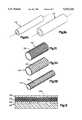
- FIG. 7is a partial sectional view of a tubular printing blanket in accordance with an alternate embodiment of the present invention.
- FIGS. 8A through 8Care schematic views showing methods of constructing the tubular printing blanket of FIG. 7;
- FIGS. 9A and 9Bare schematic views of a part of a tubular printing blanket in accordance with another alternate embodiment of the present invention.
- FIG. 10is a schematic view of a part of a tubular printing blanket in accordance with another alternate embodiment of the present invention.
- FIGS. 11A and 11Bare schematic views of a part of a tubular printing blanket in accordance with yet another alternate embodiment of the present invention.
- FIG. 12is a partial sectional view of a tubular printing blanket in accordance with an additional alternate embodiment of the present invention.
- FIG. 13is a partial sectional view of still another alternate embodiment of the invention.
- a printing apparatus 10includes a blanket cylinder 12 with a tubular printing blanket 14 constructed in accordance with the present invention.
- the printing apparatus 10is an offset printing press comprising a plurality of rolls for transferring ink from an ink fountain 16 to a printing plate 18 on a plate cylinder 20.
- the tubular printing blanket 14 on the blanket cylinder 12transfers the inked image from the printing plate 18 to a moving web 21.
- a fountain roll 22picks up ink from the ink fountain 16.
- a ductor roll 24is reciprocated between the fountain roll 22 and a first distributor roll 26 in order to transfer ink from the fountain roll 22 to the first distributor roll 26, as indicated in FIG. 1.
- a plurality of successive distributor rolls 26transfers ink from the first distributor roll 26 to a group of form rolls 28, which, in turn, transfers the ink to the printing plate 18 on the plate cylinder 20.
- a second blanket cylinder 30 with a second tubular printing blanket 32is shown only partially in FIG. 1 to represent a second printing apparatus for printing simultaneously on the opposite side of the web 21.
- the blanket cylinders 14 and 30serve as impression cylinders for each other.
- the rolls and cylindersare interconnected by gears and are rotated by a drive means 34 in a known manner.
- the ductor roll 24is moved by a reciprocating mechanism 36 in a known manner.
- the tubular printing blanket 14has a continuous, gapless inner cylindrical surface 40 firmly engaged in frictional contact with the cylindrical outer surface 42 of the blanket cylinder 12.
- the blanket cylinder 12has a central lumen 44 and a plurality of passages 46 extending radially from the central lumen 44 to the cylindrical outer surface 42.
- a source 50 of pressurized gascommunicates with the central lumen 44 in the blanket cylinder 12, and is operable to provide a flow of pressurized gas which is directed against the inner cylindrical surface 40 of the tubular printing blanket 14 from the central lumen 44 and the radially extending passages 46.
- the cylindrical inner surface 40 of the tubular printing blanket 14When a flow of pressurized gas is directed against the cylindrical inner surface 40 of the tubular printing blanket 14, the cylindrical inner surface 40 is elastically deformed in a slight amount to increase the diameter thereof.
- the tubular printing blanket 14is then easily moved telescopically on or off the blanket cylinder 12.
- the inner cylindrical surface 40 of the tubular printing blanket 14elastically contracts to its original size to grip the outer surface 42 of the blanket cylinder 12.
- the tubular printing blanket 14is then firmly engaged in frictional contact with the blanket cylinder 12 and will not move relative to the blanket cylinder 12 during operation of the printing apparatus 10.
- the tubular printing blanket 14comprises a plurality of layers.
- the layersinclude a relatively rigid backing layer 60 and a number of flexible layers supported on the backing layer 60.
- the flexible layersinclude first and second compressible layers 62 and 64, an inextensible layer 66, and a printing layer 68.
- the backing layer 60is defined by a cylindrical sleeve 70 on which the inner cylindrical surface 40 is located.
- the cylindrical sleeve 70is elastically expandable radially in a slight amount to assist telescopic movement of the tubular printing blanket 14 over the blanket cylinder 12, as described above.
- the cylindrical sleeve 70is preferably formed of metal, such as nickel with a thickness of approximately 0.005 inches, which has been found to have the requisite rigidity, strength and elastic properties.
- the cylindrical sleeve 70can be formed of a polymeric material such as fiberglass or plastic, e.g. Mylar (TM), having a thickness of approximately 0.030 inches.
- primer 71 and 72Two coats of primer 71 and 72 help to bind the first compressible layer 62 to the backing layer 60.
- the backing layer 60is a nickel cylinder
- the primer coat 71is preferably Chemlok 205
- the primer coat 72is preferably Chemlok 220, both available from Lord Chemical.
- the first compressible layer 62as shown in FIG. 3, comprises a seamless tubular body 74 of elastomeric material and a plurality of compressible microspheres 76 encapsulated in the tubular body 74.
- the first compressible layer 62further comprises a compressible thread 80 extending helically through the tubular body 74 and around the backing layer 60.
- the thread 80is impregnated with the elastomeric material of the tubular body 74 and with the microspheres 76.
- the second compressible layer 64similarly comprises a seamless tubular body 90 of elastomeric material, a plurality of compressible microspheres 92 encapsulated in the tubular body 90, and a compressible thread 94 extending helically through the tubular body 90 and around the first compressible layer 62.
- the elastomeric material of which the seamless tubular bodies 74 and 90 are formedis preferably mixed with the microspheres 76 to form a compressible, composite rubber cement having the following composition:
- microspheres 76 and 92are preferably those known by the trademark Expancel 461 DE from Expancel of Sundsvall, Sweden. Such microspheres have a shell consisting basically of a copolymer of vinylidene chloride and acrylonitrile, and contain gaseous isobutane. Other microspheres possessing the desired properties of compressibility can also be employed, such as those disclosed in U.S. Pat. No. 4,770,928.
- the compressible threads 80 and 94are preferably cotton threads having diameters of approximately 0.005 to 0.030 inches, and most preferably having diameters of approximately 0.015 inches.
- the individual windings of thread, i.e. adjacent circumferential sections thereof,are preferably spaced axially from each other a distance of approximately 0.01 inches. Such close spacing assures that there are no substantial gaps between adjacent windings.
- the threads 80 and 94can be of other compressible materials, or can be replaced with compressible tubes.
- the inextensible layer 66comprises a seamless tubular body 100 of elastomeric material and a longitudinally inextensible thread 102 within the tubular body 100.
- the thread 102extends helically through the tubular body 100 and around the second compressible layer 64.
- the thread 102is preferably cotton with a diameter of approximately 0.007 inches, and with adjacent windings thereof spaced apart a distance of approximately 0.001 inches. The thread 102 thus extends in a tight helix in which adjacent windings extend in directions substantially perpendicular to the longitudinal axis of the tubular printing blanket 14.
- the thread 102 in the longitudinal directionhas a modulus of elasticity of not less than 100,000 lbs. per square inch, and in the preferred embodiment has a modulus of elasticity of about 840,000 lbs. per square inch.
- the elastomeric material of the seamless tubular body 100has a modulus of elasticity of about 540 lbs. per square inch.
- the thread 102thus has a modulus of elasticity of not less than about 185 times the modulus of elasticity of the elastomeric material of which the seamless tubular body 100 is formed, and preferably has a modulus of elasticity of about 1,555 times the modulus of elasticity of the elastomeric material.
- the helix of thread 102thus defines a circumferentially inextensible tubular sublayer which contrains the tubular body 100 from extending circumferentially.
- the thread 102is impregnated with the elastomeric material of the tubular body 100.
- the inextensible layer 66could be formed of a seamless tubular body of rubber or urethane copolymer material having a modulus of elasticity in the range of 1,000-6,000 lbs. per square inch, and not including a sublayer of the thread 102. Such materials are available under the trademark "Airthane” from Air Products and Chemicals, Inc.
- the printing layer 68is a seamless and gapless tubular body having a smooth and gapless cylindrical outer printing surface 110. It is formed of a relatively soft elastomeric material, such as rubber, which yields slightly to become indented under the pressure applied to the tubular printing blanket 14 at the nip 112 between the blanket cylinder 12 and the plate cylinder 20 (FIGS. 1 and 4). Since the printing layer 68 is elastically yieldable, it helps to maintain a uniform pressure at the nip 112 to assure an even transfer of the inked image.
- the printing layer 68preferably has the following composition:
- the cylindrical outer printing surface 110 on the tubular printing blanket 14moves through the nip 112 between the plate cylinder 20 and the blanket cylinder 12, as shown in FIG. 4.
- the flexible layers 62-68 of the tubular printing blanket 14are indented by the rigid surface of the printing plate 18 at the nip 112.
- the printing layer 68is incompressible, and thus retains its original thickness as it moves through the nip 112.
- the inextensible layer 66is slightly compressible due to the compressibility of the thread 102, and thus becomes slightly compressed as it moves through the nip 112.
- the thread 102is longitudinally inextensible, and restrains the inextensible layer 66 from bulging radially outward as it enters and exits the nip 112.
- the inextensible layer 66prevents the portion of the printing layer in the printing nip from stretching in a circumferential direction more than 0.001 inches, and in fact in the preferred embodiment the portion of the printing layer in the printing nip stretches substantially less than 0.001 inches.
- the inextensible layer 66also thoroughly prevents the formation of standing waves in the printing layer 68 on opposite sides of the nip (see prior art FIG. 5). Such standing waves lead to smearing of the ink.
- the first and second compressible layers 62 and 64are both compressed at the nip 112. It is known that compressible portions of a printing blanket become heated when repeatedly compressed and expanded during use. In the compressible layers 62 and 64, the cotton material of the compressible threads 80 and 94 has a lesser tendency to become heated than does the elastomeric material of the tubular bodies 74 and 90.
- the tubular printing blanket 14 in accordance with the inventionthus has a low tendency to become overheated in use because the compressible layers 62 and 64 are at least partially formed of a material that runs cooler than the elastomeric material.
- the printing layer 68 and the elastomeric bodies 74, 90 and 100 of the layers 62-66 beneath the printing layer 68are continuous and seamless tubular bodies with no gaps or seams. Moreover, the helically wound threads 80, 94 and 102 do not define seams or gaps extending axially along the length of the tubular printing blanket 14.
- the cross-sectional shape of the tubular printing blanket 14 moving through the nip 112therefore remains constant throughout each complete rotation of the blanket cylinder 12.
- the pressure relationship between the outer printing surface 110 and the printing plate 18likewise remains constant throughout movement of the outer printing surface 110 past the nip 112. Shocks and vibrations experienced with known printing blankets having axially extending gaps are thus avoided, and a smooth transfer of the inked image is assured.
- the present inventionfurther contemplates methods of manufacturing a tubular printing blanket.
- the primer coat 71 of Chemlok 205is applied on the cleaned outer surface of the backing layer 60, and is aged for about 30 minutes.
- the second primer coat 72 of Chemlok 220is then applied and aged for about 30 minutes.
- the first compressible layer 62is then applied over the primed backing layer 60 by encapsulating the thread 80 in the compressible composite rubber cement, and by winding the encapsulated thread 80 in a helix around the primed backing layer 60.
- the thread 80is encapsulated in the rubber cement by drawing the thread 80 through the rubber cement in a container 120.
- the thread 80is drawn through the rubber cement in the container 120 as it is wound onto the backing layer 60 from a spool 122. An additional quantity of the rubber cement is then applied over the wound thread 80 as needed to define an additional thickness of the first compressible layer 62 in the region 126 shown in FIG. 3.
- the first compressible layer 62is then aged for two hours and oven dried for four hours at 140° F.
- the second compressible layer 64is formed in the same manner. If desired, additional windings of compressible thread can be included in either or both of the compressible layers 62 and 64.
- the inextensible layer 66 shown in FIG. 3is formed by similarly encapsulating the thread 102 in an elastomeric material without microspheres, and by winding the encapsulated thread 102 in a helix around the second compressible layers 62 and 64.
- the encapsulated thread 102is preferably impregnated thoroughly with the elastomeric material, and is wound in tension so as to apply a radially compressive preload to the compressible layers 62 and 64.
- the inextensible layer 66is then air dried for fifteen minutes.
- a sheet of uncured print rubber 0.040 inches thickis wrapped over the outside of the incompressible layer 66 to form the printing layer 68.
- the resulting structureis wrapped with a 2.25 inch nylon tape (not shown), and is oven cured for four hours at 200° F. and four hours at 292° F.
- the adjoining edges of the wrapped sheetare skived, and become bonded together when cured so that the finished printing layer 68 has no axially extending seam.
- the overlying bodies 74, 90 and 100 of elastomeric materialalso become bonded together when cured.
- the layers 62-68can then be identified individually by their different components as shown in FIG. 4, but are not separate from each other.
- the elastomeric materials of the layers 62-68define a single, continuous seamless tubular body of elastomeric material when cured. Since the inextensible layer 66 is also compressible, the layers 62-66 effectively define a composite compressible layer having a lower portion containing compressible thread and microspheres, and an upper portion containing compressible thread without microspheres. After curing, the tape is removed and the printing layer 68 is ground to a thickness of about 0.013 to 0.020 inches, and is finished to define the smooth continuous outer printing surface 110.
- FIG. 7shows an alternate embodiment of a compressible layer for a tubular printing blanket in accordance with the present invention.
- the compressible layer 150 shown in FIG. 7comprises a seamless tubular body 152 of elastomeric material, microspheres 154, and ground cotton fibers 156.
- the microspheres 154 and the ground cotton fibers 156are uniformly distributed within the tubular body 152 so as to impart compressibility to the layer 150.
- the ground cotton fibers 156have a relatively low tendency to become overheated when repeatedly compressed at a nip between a blanket cylinder and a plate cylinder.
- FIGS. 8A and 8Bschematically illustrate methods of applying the compressible layer 150 to a measured thickness over the primed backing layer 60 by metering a compressible composite rubber cement with a doctor roll 158 and with a doctor blade 160, respectively.
- FIG. 8Cschematically illustrates a method of applying the compressible layer 150 by spraying a compressible composite rubber cement to a measured thickness over the primed backing layer 60.
- the printing layer 68could alternately be formed by metering or spraying the rubber material, and/or the compressible layers 62, 64, and 150 could alternately be formed by wrapping calendared sheets with skived edges that do not define axially extending seams when cured.
- FIGS. 9A and 9Bschematically illustrate another alternate embodiment of a compressible layer for a tubular printing blanket in accordance with the invention.
- a compressible layer 170is formed as a seamless cylindrical casting.
- the compressible layer 170is formed of the same materials as the compressible layer 150 described above, and has an inside diameter not greater than the outside diameter of the backing layer 60.
- the compressible layer 170is movable telescopically over the backing layer 60.
- the compressible layer 170is then permitted to contract so as to be installed in a condition of radial and circumferential tension.
- FIG. 10schematically illustrates an alternate embodiment of a circumferentially inextensible sublayer of a tubular printing blanket in accordance with the invention.
- the longitudinally inextensible thread 102is woven to form a tube 200 which is movable telescopically over the compressible layers 62 and 64 shown in FIG. 3.
- the pattern of the woven thread 102does not permit axial or radial expansion of the tube 200.
- a quantity of elastomeric materialis applied to a shallow depth over the second compressible layer 64, and the tube 200 is then moved telescopically over the elastomeric material and the second compressible layer 64.
- Additional elastomeric materialis then applied as needed over the tube 200 so as to encapsulate and saturate the thread 102 and to provide the desired thickness of the completed inextensible layer.
- the thread 102can be shrunk with the application of heat.
- the shrunken tube 200would be in circumferential and axial tension, and would apply a radially compressive preload to the underlying compressible layers 62 and 64.
- FIGS. 11A and 11Bschematically illustrate another alternate embodiment of a circumferentially inextensible sublayer of a tubular printing blanket in accordance with the invention.
- the longitudinally inextensible thread 102is knitted to form a tube 210 which is movable telescopically over the compressible layers 62 and 64 shown in FIG. 3.
- the pattern of the knitted thread 102permits the tube 210 to be axially elongated with a resultant reduction in its diameter, as indicated in FIG. 11B.
- an elastomeric materialis applied to a shallow depth over the second compressible layer 64, and the tube 210 is moved telescopically over the elastomeric material and the compressible layer 64.
- the tube 210is then elongated axially so as to reduce its diameter.
- the elongated tube 210is in circumferential and axial tension, and thereby applies a radially compressive preload to the underlying compressible layers 62 and 64.
- Additional elastomeric materialis applied over the elongated tube 210 so as to impregnate the thread 102 and to complete the inextensible layer to a desired thickness.
- the elastomeric materialwhen cured, defines a seamless tubular body encapsulating the elongated tube 210.
- FIG. 12is a sectional view of another alternate embodiment of a circumferentially inextensible sublayer of a tubular printing blanket in accordance with the invention.
- a continuous piece of plastic film 230extends in a spiral through the elastomeric material 232 of an inextensible layer and around a compressible layer 234.
- the film 230preferably has a width approximately equal to the length of the tubular printing blanket, and a thickness of only 0.001 inches so that the narrow seam defined by the 0.001 inch wide edge 236 of the uppermost layer thereof will not disrupt the smooth, continuous cylindrical contour of an overlying printing layer.
- FIG. 13is a partial sectional view of another alternate embodiment of the invention.
- a tubular printing blanket 250comprises a relatively rigid backing layer 252, a pair of seamless tubular rubber cement layers 254 and 256 including microspheres, and a pair of tubular compressible fabric layers 258 and 260.
- the compressible fabric layers 258 and 260are preferably formed as woven or knitted tubes as shown in FIGS. 10, 11A and 11B.
- the upper compressible fabric layer 260is most preferably installed as a circumferentially inextensible tube so as to define an inextensible layer of the tubular printing blanket 250.
- An intermediate layer 262 of plain rubber cementhelps to bond a tubular printing layer 264 to the upper compressible fabric layer 260.
Landscapes
- Printing Plates And Materials Therefor (AREA)
Abstract
Description
______________________________________ PARTS ______________________________________ 1. Copolymer of Butadiene and 480.00 Acrylonitrile with 50 parts DOP 2. Soft sulfur factice 40.00 3. Acrylonitrile/Butadiene copolymer 80.00 4. Medium thermal carbon black 360.00 5. Barium Sulfate 80.00 6. Dioctyl Phthalate 40.00 7. Benzothiazyl Disulfide accelerator 8.00 8. Tetramethyl-Thiuram Disulfide 4.00 accelerator 9. Sulfur with magnesium carbonate 4.00 10. Zinc Oxide activator 20.00 11. Butyl Eight 2% by weight of adding lines 1 thru 10 12. Microspheres 6% by weight of adding lines 1 thru 11 13. Toluene 2.5 times weight of adding lines 1 thru 12 ______________________________________
______________________________________ PARTS ______________________________________ 1. Polysulfide polymer 20.00 2. Acrylonitrile/Butadiene copolymer 120.00 3. Vulcanized vegetable oil 10.00 4. Medium thermal carbon black 90.00 5. Barium Sulfate 20.00 6. Polyester glutarate 10.00 7. Proprietary curative in nitrile 15.90 polymer 8. Benzothiazyl Disulfide accelerator 2.00 9. Tetramethyl-Thiuram Disulfide 1.00accelerator 10. 75% Ethylene Thiourea/25% EPR 0.20 binder accelerator ______________________________________
Claims (1)
Priority Applications (2)
| Application Number | Priority Date | Filing Date | Title |
|---|---|---|---|
| US08/129,551US5553541A (en) | 1989-10-05 | 1993-09-29 | Gapless tubular printing blanket |
| US08/684,648US5768990A (en) | 1989-10-05 | 1996-07-19 | Gapless tubular printing blanket |
Applications Claiming Priority (3)
| Application Number | Priority Date | Filing Date | Title |
|---|---|---|---|
| US41758789A | 1989-10-05 | 1989-10-05 | |
| US69966891A | 1991-05-14 | 1991-05-14 | |
| US08/129,551US5553541A (en) | 1989-10-05 | 1993-09-29 | Gapless tubular printing blanket |
Related Parent Applications (1)
| Application Number | Title | Priority Date | Filing Date |
|---|---|---|---|
| US69966891AContinuation | 1989-10-05 | 1991-05-14 |
Related Child Applications (1)
| Application Number | Title | Priority Date | Filing Date |
|---|---|---|---|
| US08/684,648ContinuationUS5768990A (en) | 1989-10-05 | 1996-07-19 | Gapless tubular printing blanket |
Publications (1)
| Publication Number | Publication Date |
|---|---|
| US5553541Atrue US5553541A (en) | 1996-09-10 |
Family
ID=27023780
Family Applications (3)
| Application Number | Title | Priority Date | Filing Date |
|---|---|---|---|
| US08/129,551Expired - LifetimeUS5553541A (en) | 1989-10-05 | 1993-09-29 | Gapless tubular printing blanket |
| US08/342,484Expired - LifetimeUS5440981A (en) | 1989-10-05 | 1994-11-21 | Offset lithographic printing press including a gapless tubular printing blanket |
| US08/684,648Expired - LifetimeUS5768990A (en) | 1989-10-05 | 1996-07-19 | Gapless tubular printing blanket |
Family Applications After (2)
| Application Number | Title | Priority Date | Filing Date |
|---|---|---|---|
| US08/342,484Expired - LifetimeUS5440981A (en) | 1989-10-05 | 1994-11-21 | Offset lithographic printing press including a gapless tubular printing blanket |
| US08/684,648Expired - LifetimeUS5768990A (en) | 1989-10-05 | 1996-07-19 | Gapless tubular printing blanket |
Country Status (1)
| Country | Link |
|---|---|
| US (3) | US5553541A (en) |
Cited By (33)
| Publication number | Priority date | Publication date | Assignee | Title |
|---|---|---|---|---|
| US5950536A (en)* | 1998-01-23 | 1999-09-14 | Imprimeries Transcontinental, Inc. | Variable cutoff offset press unit |
| US6075955A (en)* | 1998-01-23 | 2000-06-13 | Mitsubishi Chemical America, Inc. | Noise reducing device for photosensitive drum of an image forming apparatus |
| US6125753A (en)* | 1997-05-28 | 2000-10-03 | Rollin S.A. | Sleeve for a printing machine cylinder and method of putting this sleeve in place |
| US6257140B1 (en) | 1999-12-27 | 2001-07-10 | Heidelberger Druckmaschinen Ag | Continuous process gapless tubular lithographic printing blanket |
| US6393247B1 (en) | 2000-10-04 | 2002-05-21 | Nexpress Solutions Llc | Toner fusing station having an internally heated fuser roller |
| US6456816B1 (en) | 2000-10-04 | 2002-09-24 | Nexpress Solutions Llc | Method and apparatus for an intermediate image transfer member |
| US6463250B1 (en) | 2000-10-04 | 2002-10-08 | Nexpress Solutions Llc | Externally heated deformable fuser roller |
| US6490430B1 (en) | 2000-10-04 | 2002-12-03 | Nexpress Solutions Llc | Externally heated roller for a toner fusing station |
| EP1275520A2 (en) | 2001-06-27 | 2003-01-15 | Heidelberger Druckmaschinen Aktiengesellschaft | Process of production of a flexible rubber blanket sleeve |
| WO2003006255A1 (en) | 2001-07-10 | 2003-01-23 | Reeves Brothers, Inc. | Printing face formulary |
| WO2003006253A1 (en) | 2001-07-10 | 2003-01-23 | Reeves Brothers, Inc. | Printing blanket face and compressible layer compositions |
| WO2003006254A1 (en) | 2001-07-10 | 2003-01-23 | Reeves Brothers, Inc. | Polymeric sleeve used in printing blanket |
| US20030116044A1 (en)* | 2001-07-10 | 2003-06-26 | Buono Ronald M. | Spray coating method of producing printing blankets |
| US6593061B2 (en)* | 2000-03-15 | 2003-07-15 | Fuji Photo Film Co., Ltd. | Heat-sensitive lithographic printing plate, and substrate for the plate and method of producing the same |
| US20030160159A1 (en)* | 2002-02-23 | 2003-08-28 | Kuo-Chen Chung | Hand-hold rotation gravity driving optical encoder |
| US6615721B1 (en) | 2000-11-20 | 2003-09-09 | Heidelberger Druckmaschinen Ag | Method and device for manufacturing a tubular lithographic printing blanket |
| US6688226B2 (en) | 2000-10-03 | 2004-02-10 | Erminio Rossini, S.P.A. | Sleeve for blanket cylinder of an indirect or offset printing machine and method of making said sleeve |
| WO2003072267A3 (en)* | 2002-02-25 | 2004-06-03 | Ames Rubber Corp | Elastomeric coated articles and method of manufacture |
| US20040144276A1 (en)* | 1999-10-20 | 2004-07-29 | Man Roland Druckmaschinen Ag | Rubber blanket cylinder sleeve for web fed rotary printing machines |
| US6769363B2 (en) | 2001-06-27 | 2004-08-03 | Heidelberger Druckmaschinen Ag | Device and method for manufacturing a tubular printing blanket |
| US6799511B2 (en) | 2002-12-03 | 2004-10-05 | Day International, Inc. | Gapless compressible cylinder assembly |
| US20050001374A1 (en)* | 2003-04-17 | 2005-01-06 | Kyocera Mita Corporation | Image forming apparatus |
| US6848364B1 (en)* | 1999-10-15 | 2005-02-01 | Mlp U.S.A., Inc. | Seamed sleeved blanket and method for making and using same |
| US20050166775A1 (en)* | 2002-04-18 | 2005-08-04 | Ralf Christel | Blanket on a roller, arrangements of the roller relative to a second roller, and printing units of a printing machine equipped with the roller |
| US7011021B2 (en) | 2001-09-10 | 2006-03-14 | Day International, Inc. | Printing blanket sleeve with replaceable printing surface |
| US20060219115A1 (en)* | 2005-03-30 | 2006-10-05 | Goss International Americas, Inc. | Web offset printing press with autoplating |
| US20060219111A1 (en)* | 2005-03-30 | 2006-10-05 | Goss International Americas, Inc. | Print unit having blanket cylinder throw-off bearer surfaces |
| US20060225590A1 (en)* | 2005-04-11 | 2006-10-12 | Goss International Americas, Inc. | Print unit with single motor drive permitting autoplating |
| US7775159B2 (en) | 2005-03-30 | 2010-08-17 | Goss International Americas, Inc. | Cantilevered blanket cylinder lifting mechanism |
| US7849796B2 (en) | 2005-03-30 | 2010-12-14 | Goss International Americas, Inc | Web offset printing press with articulated tucker |
| US20120060999A1 (en)* | 2010-02-23 | 2012-03-15 | Yael Kowal-Blau | Removable top blanket |
| WO2012148576A1 (en)* | 2011-04-27 | 2012-11-01 | Stolle Machinery Company, Llc | Can decorator machine, ink station assembly therefor, and can decorating method employing same |
| US11383509B2 (en) | 2018-11-09 | 2022-07-12 | Ball Corporation | Metering roller for an ink station assembly of a decorator and a method of decorating a container with the decorator |
Families Citing this family (48)
| Publication number | Priority date | Publication date | Assignee | Title |
|---|---|---|---|---|
| US6374734B1 (en)* | 1989-10-05 | 2002-04-23 | Heidelberger Druckmaschinen Ag | Tubular printing blanket |
| US5522315A (en)* | 1994-03-01 | 1996-06-04 | Reeves International | Printing blanket with convex compressible layer |
| DE4415711A1 (en)* | 1994-05-04 | 1995-11-09 | Roland Man Druckmasch | Printing unit for rubber-rubber printing |
| US5832824A (en)* | 1995-02-16 | 1998-11-10 | Sumitomo Rubber Industries, Ltd. | Printing blanket |
| US5700343A (en)* | 1996-01-16 | 1997-12-23 | Reeves Brothers, Inc. | Preparation of cylindrical blanket by spreading of compressible layer |
| DE59706477D1 (en)* | 1996-07-16 | 2002-04-04 | Roland Man Druckmasch | Rubber cylinder sleeve, in particular for offset web-fed rotary printing machines |
| US6074735A (en)* | 1996-11-27 | 2000-06-13 | Sumitomo Rubber Industries, Ltd. | Printing blanket |
| US5860360A (en)* | 1996-12-04 | 1999-01-19 | Day International, Inc. | Replaceable printing sleeve |
| USRE38468E1 (en) | 1996-12-04 | 2004-03-23 | Day International, Inc. | Replaceable sleeve |
| JP2938403B2 (en)* | 1996-12-13 | 1999-08-23 | 住友ゴム工業株式会社 | Printing blanket |
| US5934192A (en)* | 1997-01-29 | 1999-08-10 | Sumitomo Rubber Industries, Ltd. | Printing blanket |
| US6050185A (en)* | 1997-11-26 | 2000-04-18 | Heidelberger Druckmaschinen Ag | Printing unit for a web-fed rotary printing press |
| JP4231119B2 (en)* | 1997-12-08 | 2009-02-25 | 東北リコー株式会社 | Impression cylinder of stencil printing machine |
| FR2776566B1 (en)* | 1998-03-27 | 2000-06-16 | Heidelberger Druckmasch Ag | PRINTING GROUP CYLINDER HAVING A PRINTING PLATE WITH ELBOWED ENDS, FIXED ON HIM, FOR ROTARY PRINTING MACHINES |
| DE19921271A1 (en)* | 1998-06-03 | 1999-12-09 | Heidelberger Druckmasch Ag | Method of conveying sheets in a printer |
| US6205920B1 (en) | 1998-09-24 | 2001-03-27 | Day International, Inc. | Continuous image transfer belt and variable image size offset printing system |
| JP2000118164A (en)* | 1998-10-14 | 2000-04-25 | Kinyosha Co Ltd | Blanket for offset printing and its manufacture |
| DE19921388A1 (en)* | 1999-05-10 | 2000-11-16 | Roland Man Druckmasch | Rotary printing press with form, transfer and impression cylinders, with heat distribution layer under rubbercloth |
| US6314879B1 (en) | 1999-05-12 | 2001-11-13 | Hurletron Incorporated | Flexographic printing apparatus |
| JP3467456B2 (en) | 1999-09-10 | 2003-11-17 | 住友ゴム工業株式会社 | Printing blanket |
| CZ20021301A3 (en)* | 1999-10-13 | 2002-07-17 | Hatec Produktions- Und Handelsgesellschaft Mbh | Substructure material for a printing device and a printing cloth intended for printing non-even materials |
| US20110045267A1 (en)* | 1999-10-13 | 2011-02-24 | Hatec Produktions- und Handels- gesellschaft mbH | Substructure material for a printing device and printer's blanket for the printing of uneven materials to be printed |
| DE19950643B4 (en)* | 1999-10-20 | 2014-03-20 | Manroland Web Systems Gmbh | Rubber cylinder sleeve, especially for offset web presses |
| DE19956149A1 (en)* | 1999-11-23 | 2001-06-07 | Roland Man Druckmasch | Inking unit for a printing press |
| US6389965B1 (en)* | 1999-12-21 | 2002-05-21 | Heidelberger Druckmaschinen Ag | Tubular printing blanket with tubular isotropic reinforcing layer |
| DE10025374A1 (en) | 2000-05-23 | 2001-11-29 | Roland Man Druckmasch | Rubber cylinder sleeve, in particular for offset web-fed rotary printing machines |
| US6366750B1 (en)* | 2000-06-19 | 2002-04-02 | Xerox Corporation | Mandrel for a photoreceptor belt formed of a rigid machinable foam material |
| WO2002000443A1 (en)* | 2000-06-26 | 2002-01-03 | Xymid, Llc | Printing cylinder sleeve assembly |
| US6640711B2 (en)* | 2002-01-15 | 2003-11-04 | Michael A. Smoot | Bridge mandrel for use as a repeat builder in a printing machine |
| US20030213387A1 (en)* | 2002-05-14 | 2003-11-20 | Heidelberger Druckmaschinen Ag | Offset printing press with multi-image plate cylinder |
| CN100376389C (en)* | 2002-06-11 | 2008-03-26 | 曼·罗兰·德鲁克马辛伦公司 | Coating device for a printing/varnishing unit in a processing machine |
| DE10228686A1 (en)* | 2002-06-27 | 2004-02-12 | Man Roland Druckmaschinen Ag | Rubber cylinder sleeve for offset printing machines |
| WO2004016431A1 (en)* | 2002-07-19 | 2004-02-26 | Koenig & Bauer Aktiengesellschaft | Method and device for reducing vibrations on rotating parts, and vibration-damped rotating part |
| DE10257745A1 (en)* | 2002-12-10 | 2004-07-22 | Man Roland Druckmaschinen Ag | Rubber cylinder sleeve for offset printing machines |
| US7073435B2 (en)* | 2003-07-11 | 2006-07-11 | Goss International Americas, Inc. | Printing blanket with convex carrier layer |
| US20060137551A1 (en)* | 2004-12-23 | 2006-06-29 | Duchenaud Uniflexo | Compensator sleeve for flexographic printing |
| US8783178B2 (en)* | 2005-11-09 | 2014-07-22 | Day International, Inc. | Printing blanket including a non-extensible backing layer and a relief area which may be mounted in a variety of lockup mechanisms |
| NL1030670C2 (en)* | 2005-12-14 | 2007-06-15 | Stork Prints Bv | Rotary printing device and method are for application of hot melt medium on substrate |
| US20080041255A1 (en)* | 2006-08-18 | 2008-02-21 | Andrew Robert L | Printing blanket having a non-extensible porous backing |
| DE102007009810A1 (en)* | 2007-02-28 | 2008-09-04 | Man Roland Druckmaschinen Ag | Rubber blanket plate for a web-fed printing press comprises a film formed on a side of a plate-like support so that one surface of the support covered by the film on the side is smaller than one surface of the support covered by the blanket |
| US8413580B2 (en) | 2007-12-21 | 2013-04-09 | Day International, Inc. | Compressible printing sleeve carrier and method of making |
| US20100307356A1 (en)* | 2008-02-04 | 2010-12-09 | Felice Rossini | Bridged sleeve/cylinder and method of making same for web offset printing machines |
| US20090193991A1 (en)* | 2008-02-04 | 2009-08-06 | Felice Rossini | Blanket sleeve and cylinder and method of making same |
| US8281716B2 (en) | 2008-12-24 | 2012-10-09 | Printing Research, Inc. | Anti-marking jackets comprised of fluoropolymer and methods of using in offset printing |
| US8578853B2 (en)* | 2008-12-24 | 2013-11-12 | Printing Research, Inc. | Anti-marking jackets comprised of attachment structure and methods of using in offset printing |
| US8424453B2 (en) | 2010-09-01 | 2013-04-23 | Printing Research, Inc. | Apparatus and method for adjusting anti-marking jackets |
| US8677899B2 (en) | 2011-01-31 | 2014-03-25 | Printing Research, Inc. | Reversible anti-marking jackets and methods of using |
| US9346258B2 (en) | 2012-05-02 | 2016-05-24 | Printing Research, Inc. | Method for cleaning anti-marking jackets |
Citations (34)
| Publication number | Priority date | Publication date | Assignee | Title |
|---|---|---|---|---|
| US1537439A (en)* | 1922-04-13 | 1925-05-12 | Charles R Griffith | Press roll for paper machines |
| US1659371A (en)* | 1923-03-24 | 1928-02-14 | Goodrich Co B F | Sponge-rubber structure and method of making the same |
| US1691336A (en)* | 1927-03-14 | 1928-11-13 | Oxford Varnish Corp | Roll |
| US1804139A (en)* | 1926-01-16 | 1931-05-05 | Frank W Adsit | Printing blanket for offset work |
| DE564221C (en)* | 1931-02-23 | 1932-11-15 | Edmond Uher Jun | Pressure bodies for printing companies |
| US2193899A (en)* | 1935-08-29 | 1940-03-19 | Oxford Varnish Corp | Method of making transfer members |
| US2315729A (en)* | 1941-10-31 | 1943-04-06 | Jas H Matthews & Company | Combination printing roll and core support |
| US3146709A (en)* | 1962-04-09 | 1964-09-01 | West Essex Printing Plate Inc | Method and apparatus for mounting printing sleeves |
| US3152387A (en)* | 1961-10-16 | 1964-10-13 | Dayco Corp | Rollers |
| DE1217981B (en)* | 1960-12-30 | 1966-06-02 | Aurelio Zatti | Printing blanket, especially for copper gravure printing machines |
| US3467009A (en)* | 1965-07-06 | 1969-09-16 | Grace W R & Co | Compressible printing roll |
| US3652376A (en)* | 1969-07-11 | 1972-03-28 | Grace W R & Co | Multi-ply press packing for the impression member in a letter press |
| US3673023A (en)* | 1970-06-24 | 1972-06-27 | Grace W R & Co | Process of producing reinforced laminate |
| US3700541A (en)* | 1970-04-11 | 1972-10-24 | Dunlop Holdings Ltd | Printers' blankets |
| US3750250A (en)* | 1972-08-31 | 1973-08-07 | Bingham S Co | Printer{40 s roller and method of making same |
| US3802952A (en)* | 1969-07-18 | 1974-04-09 | E Gurin | Biaxally stress-oriented plastic sheet laminated with nbr adhesive to rubber-coated paper |
| US4042743A (en)* | 1970-06-11 | 1977-08-16 | Uniroyal, Inc. | Compressible offset printing blanket |
| US4086386A (en)* | 1976-10-12 | 1978-04-25 | Dayco Corporation | Smash-recoverable printing blanket |
| US4093764A (en)* | 1976-10-13 | 1978-06-06 | Dayco Corporation | Compressible printing blanket |
| US4144812A (en)* | 1975-01-08 | 1979-03-20 | Strachan & Henshaw Limited | Printing sleeves |
| GB2016373A (en)* | 1978-01-30 | 1979-09-26 | Continental Gummi Werke Ag | Rollers for printing machines |
| DE2816703A1 (en)* | 1978-04-18 | 1979-10-31 | Continental Gummi Werke Ag | PRINT CLOTH |
| US4219595A (en)* | 1977-05-27 | 1980-08-26 | Continental Gummi-Werke Aktiengesellschaft | Printing blanket and method of making same |
| DE3027549A1 (en)* | 1979-07-20 | 1981-02-05 | Grace W R & Co | PRINTED CLOTH FROM AN ELASTIC, COMPRESSIBLE PRINTING ELEMENT WITH CLOSED CELL FOAM, METHOD FOR THE PRODUCTION THEREOF AND PRINTING METHOD USING THE PRINTED CLOTH |
| US4378622A (en)* | 1977-11-10 | 1983-04-05 | Dayco Corporation | Method of making compressible printing roller |
| EP0076777A1 (en)* | 1981-09-30 | 1983-04-13 | Herlitz AG | Printing cylinder |
| US4728522A (en)* | 1985-07-15 | 1988-03-01 | Mcdonnell Douglas Corporation | Process for treating hulled oilseeds |
| US4770928A (en)* | 1983-12-27 | 1988-09-13 | Day International Corporation | Method of curing a compressible printing blanket and a compressible printing blanket produced thereby |
| US4812357A (en)* | 1988-09-23 | 1989-03-14 | W. R. Grace & Co.-Conn. | Printing blanket |
| US4823693A (en)* | 1987-01-31 | 1989-04-25 | Man - Roland Druckmaschinen Ag | Printing cylinder sleeve application apparatus and method |
| US4913048A (en)* | 1985-12-11 | 1990-04-03 | Tittgemeyer Engineering | Method and apparatus for printing with a lithographic sleeve |
| EP0388740A2 (en)* | 1989-03-18 | 1990-09-26 | M.A.N.-ROLAND Druckmaschinen Aktiengesellschaft | Shell for offset-cylinder for rotary machines |
| EP0452184A1 (en)* | 1990-04-12 | 1991-10-16 | Rollin S.A. | Blanket covered cylinder |
| US5316798A (en)* | 1989-03-18 | 1994-05-31 | Man Roland Druckmaschinen Ag | Method of making a cylindrical sleeve structure, particularly cover for an offset cylinder in a rotary printing machine |
Family Cites Families (7)
| Publication number | Priority date | Publication date | Assignee | Title |
|---|---|---|---|---|
| GB1198863A (en)* | 1967-07-20 | 1970-07-15 | Maclellan Rubber Ltd | Improvements relating to Printing Rollers |
| US3674023A (en)* | 1969-07-02 | 1972-07-04 | Robert C Mann | Ankle support providing high bracing strength |
| DE2244765C3 (en)* | 1972-09-13 | 1978-07-27 | Continental Gummi-Werke Ag, 3000 Hannover | Printing blanket |
| US3887750A (en)* | 1973-01-08 | 1975-06-03 | Dayco Corp | Compressible printing blanket |
| US3881045A (en)* | 1973-07-24 | 1975-04-29 | Du Pont | Offset printing blanket |
| US4025685A (en)* | 1974-09-06 | 1977-05-24 | Dayco Corporation | Compressible printing blanket and method of manufacture |
| US4728552A (en)* | 1984-07-06 | 1988-03-01 | Rodel, Inc. | Substrate containing fibers of predetermined orientation and process of making the same |
- 1993
- 1993-09-29USUS08/129,551patent/US5553541A/ennot_activeExpired - Lifetime
- 1994
- 1994-11-21USUS08/342,484patent/US5440981A/ennot_activeExpired - Lifetime
- 1996
- 1996-07-19USUS08/684,648patent/US5768990A/ennot_activeExpired - Lifetime
Patent Citations (39)
| Publication number | Priority date | Publication date | Assignee | Title |
|---|---|---|---|---|
| US1537439A (en)* | 1922-04-13 | 1925-05-12 | Charles R Griffith | Press roll for paper machines |
| US1659371A (en)* | 1923-03-24 | 1928-02-14 | Goodrich Co B F | Sponge-rubber structure and method of making the same |
| US1804139A (en)* | 1926-01-16 | 1931-05-05 | Frank W Adsit | Printing blanket for offset work |
| US1691336A (en)* | 1927-03-14 | 1928-11-13 | Oxford Varnish Corp | Roll |
| DE564221C (en)* | 1931-02-23 | 1932-11-15 | Edmond Uher Jun | Pressure bodies for printing companies |
| US2193899A (en)* | 1935-08-29 | 1940-03-19 | Oxford Varnish Corp | Method of making transfer members |
| US2315729A (en)* | 1941-10-31 | 1943-04-06 | Jas H Matthews & Company | Combination printing roll and core support |
| DE1217981B (en)* | 1960-12-30 | 1966-06-02 | Aurelio Zatti | Printing blanket, especially for copper gravure printing machines |
| US3152387A (en)* | 1961-10-16 | 1964-10-13 | Dayco Corp | Rollers |
| US3146709A (en)* | 1962-04-09 | 1964-09-01 | West Essex Printing Plate Inc | Method and apparatus for mounting printing sleeves |
| US3467009A (en)* | 1965-07-06 | 1969-09-16 | Grace W R & Co | Compressible printing roll |
| US3652376A (en)* | 1969-07-11 | 1972-03-28 | Grace W R & Co | Multi-ply press packing for the impression member in a letter press |
| US3802952A (en)* | 1969-07-18 | 1974-04-09 | E Gurin | Biaxally stress-oriented plastic sheet laminated with nbr adhesive to rubber-coated paper |
| US3700541A (en)* | 1970-04-11 | 1972-10-24 | Dunlop Holdings Ltd | Printers' blankets |
| US4042743A (en)* | 1970-06-11 | 1977-08-16 | Uniroyal, Inc. | Compressible offset printing blanket |
| US3673023A (en)* | 1970-06-24 | 1972-06-27 | Grace W R & Co | Process of producing reinforced laminate |
| US3750250A (en)* | 1972-08-31 | 1973-08-07 | Bingham S Co | Printer{40 s roller and method of making same |
| US4144812A (en)* | 1975-01-08 | 1979-03-20 | Strachan & Henshaw Limited | Printing sleeves |
| US4086386A (en)* | 1976-10-12 | 1978-04-25 | Dayco Corporation | Smash-recoverable printing blanket |
| US4093764A (en)* | 1976-10-13 | 1978-06-06 | Dayco Corporation | Compressible printing blanket |
| US4219595A (en)* | 1977-05-27 | 1980-08-26 | Continental Gummi-Werke Aktiengesellschaft | Printing blanket and method of making same |
| US4378622A (en)* | 1977-11-10 | 1983-04-05 | Dayco Corporation | Method of making compressible printing roller |
| GB2016373A (en)* | 1978-01-30 | 1979-09-26 | Continental Gummi Werke Ag | Rollers for printing machines |
| DE2816703A1 (en)* | 1978-04-18 | 1979-10-31 | Continental Gummi Werke Ag | PRINT CLOTH |
| GB2024104A (en)* | 1978-04-18 | 1980-01-09 | Continental Gummi Werke Ag | Printing blanket |
| US4303721B1 (en)* | 1979-07-20 | 1990-07-24 | Grace W R & Co | |
| DE3027549A1 (en)* | 1979-07-20 | 1981-02-05 | Grace W R & Co | PRINTED CLOTH FROM AN ELASTIC, COMPRESSIBLE PRINTING ELEMENT WITH CLOSED CELL FOAM, METHOD FOR THE PRODUCTION THEREOF AND PRINTING METHOD USING THE PRINTED CLOTH |
| GB2056883A (en)* | 1979-07-20 | 1981-03-25 | Grace W R & Co | Closed cell foam printing blanket and foaming method |
| US4303721A (en)* | 1979-07-20 | 1981-12-01 | W. R. Grace & Co. | Closed cell foam printing blanket |
| EP0076777A1 (en)* | 1981-09-30 | 1983-04-13 | Herlitz AG | Printing cylinder |
| US4770928A (en)* | 1983-12-27 | 1988-09-13 | Day International Corporation | Method of curing a compressible printing blanket and a compressible printing blanket produced thereby |
| US4728522A (en)* | 1985-07-15 | 1988-03-01 | Mcdonnell Douglas Corporation | Process for treating hulled oilseeds |
| US4913048A (en)* | 1985-12-11 | 1990-04-03 | Tittgemeyer Engineering | Method and apparatus for printing with a lithographic sleeve |
| US4823693A (en)* | 1987-01-31 | 1989-04-25 | Man - Roland Druckmaschinen Ag | Printing cylinder sleeve application apparatus and method |
| US4812357A (en)* | 1988-09-23 | 1989-03-14 | W. R. Grace & Co.-Conn. | Printing blanket |
| US4812357B1 (en)* | 1988-09-23 | 1990-03-27 | Grace W R & Co | |
| EP0388740A2 (en)* | 1989-03-18 | 1990-09-26 | M.A.N.-ROLAND Druckmaschinen Aktiengesellschaft | Shell for offset-cylinder for rotary machines |
| US5316798A (en)* | 1989-03-18 | 1994-05-31 | Man Roland Druckmaschinen Ag | Method of making a cylindrical sleeve structure, particularly cover for an offset cylinder in a rotary printing machine |
| EP0452184A1 (en)* | 1990-04-12 | 1991-10-16 | Rollin S.A. | Blanket covered cylinder |
Non-Patent Citations (1)
| Title |
|---|
| Search Report.* |
Cited By (55)
| Publication number | Priority date | Publication date | Assignee | Title |
|---|---|---|---|---|
| US6125753A (en)* | 1997-05-28 | 2000-10-03 | Rollin S.A. | Sleeve for a printing machine cylinder and method of putting this sleeve in place |
| US5950536A (en)* | 1998-01-23 | 1999-09-14 | Imprimeries Transcontinental, Inc. | Variable cutoff offset press unit |
| US6075955A (en)* | 1998-01-23 | 2000-06-13 | Mitsubishi Chemical America, Inc. | Noise reducing device for photosensitive drum of an image forming apparatus |
| US20080034999A1 (en)* | 1999-10-15 | 2008-02-14 | Mlp U.S.A., Inc., A Delaware Corporation | Offset lithographic printing press having seamed sleeved printing blanket |
| US7131375B2 (en) | 1999-10-15 | 2006-11-07 | Mlp U.S.A., Inc. | Offset lithographic printing press having seamed sleeved printing blanket |
| US20070079715A1 (en)* | 1999-10-15 | 2007-04-12 | Mlp U.S.A., Inc, A Delaware Corporation | Offset lithographic printing press having seamed sleeved printing blanket |
| US20050139101A1 (en)* | 1999-10-15 | 2005-06-30 | Mlp U.S.A., Inc., A Delaware Corporation | Seamed sleeved blanket and method for making and using same |
| US6848364B1 (en)* | 1999-10-15 | 2005-02-01 | Mlp U.S.A., Inc. | Seamed sleeved blanket and method for making and using same |
| US7287470B2 (en) | 1999-10-15 | 2007-10-30 | Mlp U.S.A., Inc. | Offset lithographic printing press having seamed sleeved printing blanket |
| US7530306B2 (en) | 1999-10-15 | 2009-05-12 | Mlp U.S.A., Inc. | Offset lithographic printing press having seamed sleeved printing blanket |
| US6981444B2 (en) | 1999-10-15 | 2006-01-03 | Mlp U.S.A., Inc. | Seamed sleeved printing blanket |
| US20050252397A1 (en)* | 1999-10-15 | 2005-11-17 | Mlp U.S.A., Inc., A Delaware Corporation | Offset lithographic printing press having seamed sleeved printing blanket |
| US7036429B2 (en)* | 1999-10-20 | 2006-05-02 | Man Roland Druckmaschinen Ag | Rubber blanket cylinder sleeve for web fed rotary printing machines |
| US20040144276A1 (en)* | 1999-10-20 | 2004-07-29 | Man Roland Druckmaschinen Ag | Rubber blanket cylinder sleeve for web fed rotary printing machines |
| US6257140B1 (en) | 1999-12-27 | 2001-07-10 | Heidelberger Druckmaschinen Ag | Continuous process gapless tubular lithographic printing blanket |
| US6593061B2 (en)* | 2000-03-15 | 2003-07-15 | Fuji Photo Film Co., Ltd. | Heat-sensitive lithographic printing plate, and substrate for the plate and method of producing the same |
| US6688226B2 (en) | 2000-10-03 | 2004-02-10 | Erminio Rossini, S.P.A. | Sleeve for blanket cylinder of an indirect or offset printing machine and method of making said sleeve |
| US6490430B1 (en) | 2000-10-04 | 2002-12-03 | Nexpress Solutions Llc | Externally heated roller for a toner fusing station |
| US6456816B1 (en) | 2000-10-04 | 2002-09-24 | Nexpress Solutions Llc | Method and apparatus for an intermediate image transfer member |
| US6393247B1 (en) | 2000-10-04 | 2002-05-21 | Nexpress Solutions Llc | Toner fusing station having an internally heated fuser roller |
| US6463250B1 (en) | 2000-10-04 | 2002-10-08 | Nexpress Solutions Llc | Externally heated deformable fuser roller |
| US6615721B1 (en) | 2000-11-20 | 2003-09-09 | Heidelberger Druckmaschinen Ag | Method and device for manufacturing a tubular lithographic printing blanket |
| US6779451B2 (en) | 2001-06-27 | 2004-08-24 | Heidelberger Druckmaschinen Ag | Flexible tubular printing blanket |
| EP1275520A2 (en) | 2001-06-27 | 2003-01-15 | Heidelberger Druckmaschinen Aktiengesellschaft | Process of production of a flexible rubber blanket sleeve |
| US6769363B2 (en) | 2001-06-27 | 2004-08-03 | Heidelberger Druckmaschinen Ag | Device and method for manufacturing a tubular printing blanket |
| US6871591B2 (en)* | 2001-07-10 | 2005-03-29 | Reeves Brothers, Inc. | Spray coating method of producing printing blankets |
| WO2003006255A1 (en) | 2001-07-10 | 2003-01-23 | Reeves Brothers, Inc. | Printing face formulary |
| WO2003006253A1 (en) | 2001-07-10 | 2003-01-23 | Reeves Brothers, Inc. | Printing blanket face and compressible layer compositions |
| US20030116044A1 (en)* | 2001-07-10 | 2003-06-26 | Buono Ronald M. | Spray coating method of producing printing blankets |
| WO2003006254A1 (en) | 2001-07-10 | 2003-01-23 | Reeves Brothers, Inc. | Polymeric sleeve used in printing blanket |
| US7011021B2 (en) | 2001-09-10 | 2006-03-14 | Day International, Inc. | Printing blanket sleeve with replaceable printing surface |
| US20030160159A1 (en)* | 2002-02-23 | 2003-08-28 | Kuo-Chen Chung | Hand-hold rotation gravity driving optical encoder |
| WO2003072267A3 (en)* | 2002-02-25 | 2004-06-03 | Ames Rubber Corp | Elastomeric coated articles and method of manufacture |
| US7571677B2 (en) | 2002-04-18 | 2009-08-11 | Koenig & Bauer Aktiengesellschaft | Printing unit having transfer cylinder with compressible layer |
| US7194953B2 (en) | 2002-04-18 | 2007-03-27 | Koenig & Bauer Aktiengesellschaft | Dressing on a cylinder or a transfer cylinder as well as printing units of a printing press |
| US20050166775A1 (en)* | 2002-04-18 | 2005-08-04 | Ralf Christel | Blanket on a roller, arrangements of the roller relative to a second roller, and printing units of a printing machine equipped with the roller |
| US20070169648A1 (en)* | 2002-04-18 | 2007-07-26 | Ralf Christel | Dressing on a cylinder, or a transfer cylinder, as well as printing units of a printing press |
| US6799511B2 (en) | 2002-12-03 | 2004-10-05 | Day International, Inc. | Gapless compressible cylinder assembly |
| US20050001374A1 (en)* | 2003-04-17 | 2005-01-06 | Kyocera Mita Corporation | Image forming apparatus |
| US7300055B2 (en)* | 2003-04-17 | 2007-11-27 | Kyocera Mita Corporation | Image forming apparatus |
| US7775159B2 (en) | 2005-03-30 | 2010-08-17 | Goss International Americas, Inc. | Cantilevered blanket cylinder lifting mechanism |
| US7849796B2 (en) | 2005-03-30 | 2010-12-14 | Goss International Americas, Inc | Web offset printing press with articulated tucker |
| US7819057B2 (en) | 2005-03-30 | 2010-10-26 | Goss International Americas, Inc. | Print unit having blanket cylinder throw-off bearer surfaces |
| US20100294150A1 (en)* | 2005-03-30 | 2010-11-25 | Goss International Americas, Inc. | Cantilevered Blanket Cylinder Lifting Mechanism |
| US20060219115A1 (en)* | 2005-03-30 | 2006-10-05 | Goss International Americas, Inc. | Web offset printing press with autoplating |
| US8250976B2 (en) | 2005-03-30 | 2012-08-28 | Goss International Americas, Inc. | Cantilevered blanket cylinder lifting mechanism |
| US20060219111A1 (en)* | 2005-03-30 | 2006-10-05 | Goss International Americas, Inc. | Print unit having blanket cylinder throw-off bearer surfaces |
| US7516698B2 (en) | 2005-03-30 | 2009-04-14 | Goss International Americasn, Inc. | Web offset printing press with autoplating |
| US8037818B2 (en) | 2005-04-11 | 2011-10-18 | Goss International Americas, Inc. | Print unit with single motor drive permitting autoplating |
| US20060225590A1 (en)* | 2005-04-11 | 2006-10-12 | Goss International Americas, Inc. | Print unit with single motor drive permitting autoplating |
| US20120060999A1 (en)* | 2010-02-23 | 2012-03-15 | Yael Kowal-Blau | Removable top blanket |
| WO2012148576A1 (en)* | 2011-04-27 | 2012-11-01 | Stolle Machinery Company, Llc | Can decorator machine, ink station assembly therefor, and can decorating method employing same |
| US9475276B2 (en) | 2011-04-27 | 2016-10-25 | Stolle Machinery Company, Llc | Can decorator machine, ink station assembly therefor, and can decorating method employing same |
| US9884478B2 (en) | 2011-04-27 | 2018-02-06 | Stolle Machinery Company, Llc | Can decorator machine, ink station assembly therefor, and can decorating method employing same |
| US11383509B2 (en) | 2018-11-09 | 2022-07-12 | Ball Corporation | Metering roller for an ink station assembly of a decorator and a method of decorating a container with the decorator |
Also Published As
| Publication number | Publication date |
|---|---|
| US5440981A (en) | 1995-08-15 |
| US5768990A (en) | 1998-06-23 |
Similar Documents
| Publication | Publication Date | Title |
|---|---|---|
| US5553541A (en) | Gapless tubular printing blanket | |
| US5304267A (en) | Method of making a gapless tubular printing blanket | |
| US5884559A (en) | Helical thread printing blanket | |
| US7287470B2 (en) | Offset lithographic printing press having seamed sleeved printing blanket | |
| EP0612281B1 (en) | Compressible printing blanket and method of making same | |
| US5654100A (en) | Offset rubber-blanket sleeve | |
| US20040031407A1 (en) | Multi-layered gapped cylindrical printing blanket | |
| US5498470A (en) | Printing blanket having improved dynamic thickness stability and method of making | |
| JP2747198B2 (en) | Offset blanket for printing | |
| US5832824A (en) | Printing blanket | |
| US6205921B1 (en) | Variable image size offset printing system and method of printing | |
| US5700343A (en) | Preparation of cylindrical blanket by spreading of compressible layer | |
| EP0727326B1 (en) | Printing blanket | |
| JP2003080864A (en) | Printing blanket and its manufacturing method | |
| JP3126333B2 (en) | Printing blanket | |
| WO1999011468A1 (en) | Cylindrical printing blanket with tapered plastic sleeve |
Legal Events
| Date | Code | Title | Description |
|---|---|---|---|
| AS | Assignment | Owner name:HEIDELBERG HARRIS, INC., NEW HAMPSHIRE Free format text:ASSIGNMENT OF ASSIGNORS INTEREST;ASSIGNOR:AMERICAN ROLLER COMPANY;REEL/FRAME:007215/0431 Effective date:19940822 | |
| STCF | Information on status: patent grant | Free format text:PATENTED CASE | |
| CC | Certificate of correction | ||
| FEPP | Fee payment procedure | Free format text:PAYOR NUMBER ASSIGNED (ORIGINAL EVENT CODE: ASPN); ENTITY STATUS OF PATENT OWNER: LARGE ENTITY | |
| FPAY | Fee payment | Year of fee payment:4 | |
| AS | Assignment | Owner name:HEIDELBERGER DRUCKMASCHINEN AG, GERMANY Free format text:ASSIGNMENT OF ASSIGNORS INTEREST;ASSIGNOR:HEIDELBERG WEB SYSTEMS, INC. (FORMERLY KNOWN AS HEIDELBERG WEB PRESS, INC. AND/OR HEIDELBERG HARRIS, INC.);REEL/FRAME:012621/0059 Effective date:20020124 | |
| FPAY | Fee payment | Year of fee payment:8 | |
| AS | Assignment | Owner name:U.S. BANK, N.A., MINNESOTA Free format text:SECURITY AGREEMENT;ASSIGNOR:HEIDELBERG WEB SYSTEMS, INC., A DELAWARE CORPORATION;REEL/FRAME:015722/0435 Effective date:20040806 | |
| AS | Assignment | Owner name:HEIDELBERG WEB SYSTEMS, INC., NEW HAMPSHIRE Free format text:ASSIGNMENT OF ASSIGNORS INTEREST;ASSIGNOR:HEIDELBERGER DRUCKMASCHINEN AG;REEL/FRAME:015886/0211 Effective date:20040806 | |
| AS | Assignment | Owner name:GOSS INTERNATIONAL AMERICAS, INC., NEW HAMPSHIRE Free format text:CHANGE OF NAME;ASSIGNOR:HEIDELBERG WEB SYSTEMS, INC.;REEL/FRAME:015886/0713 Effective date:20040809 | |
| FEPP | Fee payment procedure | Free format text:PAYER NUMBER DE-ASSIGNED (ORIGINAL EVENT CODE: RMPN); ENTITY STATUS OF PATENT OWNER: LARGE ENTITY Free format text:PAYOR NUMBER ASSIGNED (ORIGINAL EVENT CODE: ASPN); ENTITY STATUS OF PATENT OWNER: LARGE ENTITY | |
| FPAY | Fee payment | Year of fee payment:12 | |
| REMI | Maintenance fee reminder mailed | ||
| AS | Assignment | Owner name:U.S. BANK NATIONAL ASSOCIATION, AS COLLATERAL AGEN Free format text:SECURITY AGREEMENT;ASSIGNOR:GOSS INTERNATIONAL AMERICAS, INC.;REEL/FRAME:022960/0316 Effective date:20090710 | |
| AS | Assignment | Owner name:GOSS INTERNATIONAL AMERICAS, INC., ILLINOIS Free format text:RELEASE OF SECURITY INTEREST (GRANTED IN REEL 022960; FRAME 0316);ASSIGNOR:U.S. BANK, N.A., NATIONAL ASSOCIATION;REEL/FRAME:025012/0889 Effective date:20100914 | |
| AS | Assignment | Owner name:SHANGHAI ELECTRIC (GROUP) CORPORATION, CHINA Free format text:ASSIGNMENT OF ASSIGNORS INTEREST;ASSIGNOR:GOSS INTERNATIONAL CORPORATION;REEL/FRAME:048304/0460 Effective date:20101231 |