US5553183A - Apparatus for and methods of splitting fiber optic signals - Google Patents
Apparatus for and methods of splitting fiber optic signalsDownload PDFInfo
- Publication number
- US5553183A US5553183AUS08/415,194US41519495AUS5553183AUS 5553183 AUS5553183 AUS 5553183AUS 41519495 AUS41519495 AUS 41519495AUS 5553183 AUS5553183 AUS 5553183A
- Authority
- US
- United States
- Prior art keywords
- fiber optic
- signals
- optic signal
- splitters
- splicing
- Prior art date
- Legal status (The legal status is an assumption and is not a legal conclusion. Google has not performed a legal analysis and makes no representation as to the accuracy of the status listed.)
- Expired - Lifetime
Links
- 239000000835fiberSubstances0.000titleclaimsabstractdescription269
- 238000000034methodMethods0.000titleclaimsabstractdescription7
- 239000013307optical fiberSubstances0.000claimsabstractdescription40
- 239000000463materialSubstances0.000claimsdescription2
- 230000003287optical effectEffects0.000claims1
- 230000004927fusionEffects0.000description2
- 238000001746injection mouldingMethods0.000description2
- 230000014759maintenance of locationEffects0.000description2
- 239000004593EpoxySubstances0.000description1
- 239000000853adhesiveSubstances0.000description1
- 230000001070adhesive effectEffects0.000description1
- 238000005452bendingMethods0.000description1
- 230000000881depressing effectEffects0.000description1
- 238000012986modificationMethods0.000description1
- 230000004048modificationEffects0.000description1
- 238000000465mouldingMethods0.000description1
- 239000007787solidSubstances0.000description1
- 229920002725thermoplastic elastomerPolymers0.000description1
- 239000012815thermoplastic materialSubstances0.000description1
Images


Classifications
- G—PHYSICS
- G02—OPTICS
- G02B—OPTICAL ELEMENTS, SYSTEMS OR APPARATUS
- G02B6/00—Light guides; Structural details of arrangements comprising light guides and other optical elements, e.g. couplings
- G02B6/44—Mechanical structures for providing tensile strength and external protection for fibres, e.g. optical transmission cables
- G02B6/4439—Auxiliary devices
- G02B6/444—Systems or boxes with surplus lengths
- G02B6/4453—Cassettes
- G02B6/4454—Cassettes with splices
Definitions
- the present inventionrelates to apparatus and methods for splitting fiber optic signals which signals, as known to those skilled in the art, are signals transmitted through optical fibers.
- Apparatus satisfying the foregoing object and embodying the present inventionmay include fiber optic signal splitter apparatus for receiving an incoming fiber optic signal and for splitting the incoming fiber optic signal into a first plurality of fiber optic signals, fiber optic splicing apparatus for splicing the first plurality of fiber optic signals to the fiber optic signal splitter apparatus which splits the first plurality of fiber optic signals into a second plurality of fiber optic signals greater in number than the first plurality of fiber optic signals.
- the present inventionfurther includes such fiber optic signal splicing apparatus in combination with a splice tray for splicing an incoming optical fiber to the apparatus and for splicing a plurality of optical fibers to receive the second plurality of optical fiber signals.
- Method satisfying the foregoing object and embodying the present inventionmay include the steps of splitting an incoming fiber optic signal into a first plurality of fiber optic signals, splicing the first plurality of fiber optic signals to a plurality of optic fiber signal splitters equal in number to the first plurality of fiber optic signals to cause the plurality of fiber optic signal splitters to split the first plurality of fiber optic signals into a second plurality of fiber optic signals larger in number than the first plurality of fiber optic signals.
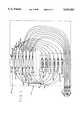
- FIG. 1is a diagrammatical illustration of an embodiment of fiber optic signal splitter apparatus of the present invention
- FIG. 2is a perspective view of an actual embodiment of fiber optic signal splitter apparatus of the present invention
- FIG. 3is an exploded perspective view of the cover and base comprising the apparatus of FIG. 2;
- FIG. 3Ais a partial vertical view, in cross-section, of a groove provided in the base shown in FIG. 3 and illustrating strain relief;
- FIG. 4is a partial vertical view illustrating the substantially non-removable attachment of the cover to the base shown in FIG. 3;
- FIG. 5is a perspective view of an alternate embodiment of fiber optic signal splitter apparatus of the present invention.
- FIG. 6is a perspective view of the cover of the apparatus of FIG. 5;
- FIG. 7is an exploded view in perspective of the base of the apparatus shown in FIG. 5;
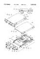
- FIG. 8is an exploded perspective view of a further embodiment of the present invention including in combination the apparatus shown in FIG. 2 and fiber optic splice tray apparatus for organizing and storing spliced optical fibers.
- Apparatus 10includes an individual fiber optic signal splitter 12, a first plurality of fiber optic signal splitters indicated by general numerical designation 14 and including individual fiber optic signal splitters 15 and 16, a second plurality of fiber optic signal splitters including a plurality of individual fiber optic signal splitters 20-23, a first plurality of fiber optic splicing means or members indicated by general numerical designation 24 and including individual fiber optic splicing means or members 25 and 26 and a second plurality of fiber optic splicing means or members indicated by general numerical designation 30 and including individual fiber optic splicing means or members 31-34.
- the individual fiber optic splittersare 1 to 2 splitters, and the individual fiber optic splicing means or members are single fusion optical fiber splices.
- Individual optical fiber signal splitter 12includes an input lead 36 and a pair of output leads 37 and 38.
- An incoming fiber optic signalis transmitted through the input lead 36 and the splitter 12 splits the incoming fiber optic signal into a pair of outgoing fiber optic signals transmitted through the output leads 37 and 38.
- Output leads 37 and 38are spliced respectively by individual optical fiber splicing members 25 and 26 to the input leads 40 and 41 of individual fiber optic signal splitters 15 and 16, respectively.
- the splitters 15 and 16split such signals into four outgoing fiber optic signals transmitted through the pairs of output leads 43 and 44 and 45 and 46 of the respective splitters 15 .and 16.
- the output leads 43-46are spliced, respectively, by the individual optical fiber splicing members 31-34 to the input leads 49-51 of the respective individual fiber optic signal splitters 20-23.
- the four fiber optic signalsare split into eight outgoing fiber optic signals transmitted through the pairs of output leads 53 and 54, 55 and 56, 57 and 58 and 59 and 60 of the fiber optic signal splitters 20-23.
- These output leads 53-60note the lower lefthand portion of FIG. 1, present the eight fiber optic signals for connection to fiber optic signal utilization devices or apparatus such as telephone equipment, television equipment, data equipment and the like.
- the first plurality of fiber optic signal splitters 14may comprise an additional number or numbers of individual fiber optic signal splitters and in such event the number of individual fiber optic signal splitters comprising the second plurality of fiber optic signal splitters 18 and the pluralities of individual splicing members comprising the first and second pluralities of fiber optic splicing means 24 and 30 will be increased in number accordingly.
- the individual fiber optic signal splitter 12may be of the type which splits incoming fiber optic signals into three or more outgoing fiber optic signals, and in such event it will be understood that the pluralities of fiber optic signal splitters of the pluralities 14 and 18 and the pluralities of the fiber optic splicing members of the pluralities 24 and 30 will be increased in number accordingly. Referring again to FIG.
- fiber optic signal splitter apparatusmay include only the individual splitter 12, the first plurality of optical fiber signal splitters 14 and the first plurality of optical fiber splicing means 24 whereby the four output leads 43-46 of the individual fiber optic signal splitters 15 and 16 will provide four outgoing fiber optic signals from which the incoming fiber optic signal received on input lead 36 is split.
- apparatus 61includes a cover indicated by general numerical designation 62 and a base indicated by general numerical designation 63, apparatus 61 has an entrance end indicated by general numerical designation 65.
- the cover 62is mounted to the base 63 to provide the unitary apparatus 61, or the assembly, shown in FIG. 2.
- the fiber optic signal splitters and fiber optic splicing means shown in FIG. 1are also shown in FIG. 3 and given the same numerical designations for convenience of reference.
- the base 63has an entrance end indicated by general numerical designation 67 and is provided with first mounting means, or splitter holder, indicated by general numerical designation 64 and second mounting means, or splice holder, indicated by general numerical designation 66.
- Mounting means 64is comprised of a plurality of pairs of upwardly extending and opposed members, such as for example representative pair of upwardly extending and opposed members 68 and 69 for wedgedly and removably receiving fiber optic signal splitter 23.
- Mounting means 66may comprise an integrally formed member 70 which may be formed of a suitable flexible material such as a suitable thermoplastic elastomer and may be made by a suitable molding operation such as suitable injection molding; the bottom of the member 70 may be mounted to the base 63 by a suitable adhesive.
- the member 70provides a plurality of inwardly extending grooves, as shown, for wedgedly and removably receiving the fiber optic splicing means 25 and 26 and 31-34.
- the base 63may be provided with a plurality of optical fiber retaining members 74-79, mounted removably to the base 63, for facilitating retention of the input and output leads, shown in FIG. 1 and described above, on the base means 63.
- the retaining members 74-79may have the same structure as the retaining members 35-42 described in the '185 patent and shown particularly in FIG. 3 of the '185 patent. It will be further understood that the retaining members 74-79 may have either the structure shown for the representative retaining member 42 in FIG. 5, or in FIG. 5A, of the '185 patent. Further, the base 63 may be provided with a generally semi-circular curvature imparting member 80 for imparting a radius of curvature to the output leads shown in the righthand portion of FIG. 1, which radius of curvature is less than the minimum bending radius for such fiber optic output leads.
- Base 63further includes pluralities of upwardly extending members indicated by general numerical designations 82 and 84, FIG. 3, which provide a plurality of grooves therebetween for receiving the input lead 36, FIG. 1, and the output leads 53-60, FIG. 1.
- the input lead 36, FIG. 1may enter the groove 86 and the output leads 53-60, FIG. 1, may exit the other grooves provided by the plurality of upwardly extending members 82 and 84 with an extra groove being provided.
- the groovesmay be provided with a cavity, e.g. cavity 87, for receiving a suitably epoxy 85 which surrounds the input and output filter optic leads, e.g.
- Cover 62FIGS. 2 and 3, is provided with a pair of outwardly extending members 62A and 62B for overlying and covering the grooves 82 and 84.
- cover 62is mounted to the base 63 in a substantially non-removable fashion to provide the closed or unitary apparatus or assembly shown in FIG. 2.
- the cover 62FIG. 4 may be provided with four pairs of downwardly extending, slightly flexible, notched members, representative pair of notched members 88 and 89 shown in FIG. 4, for being received and substantially non-removably latched into four openings or holes 91-94 formed in base 63; representative hole or opening 94 is shown in FIG. 4.
- cover 62is not mounted substantially non-removably to the base 63 until after the fiber optic signal splitters 12, 15 and 16 and 20-23 and fiber optic splicing means 25 and 26 and 31-34 are mounted to the base and the input and output leads arranged as indicated diagrammatically in FIG. 1.
- FIGS. 5-7A further alternate embodiment of fiber optic signal splitter apparatus embodying the present invention is illustrated in FIGS. 5-7 and indicated by general numerical designation 161.
- cover 162 and base 163 of the apparatus 161are mounted together in a substantially non-removable manner in the same manner as described above with regard to the cover and base 62 and 63 and as illustrated in FIG. 4.
- cover 162, FIG. 6,is higher than cover 62, FIG. 3, to accommodate fastening of a panel 165, FIG. 7, to the apparatus 161.
- base 163is substantially the same as base 63 shown in FIG. 3 and described above and that the structural elements in the base 163 which are the same as the structural elements of the base 63 are given the same numerical designations for convenience of reference.
- Base 163, FIG. 7,differs from base 63 of FIG. 3 in that base 163 is provided with holes or apertures 101 and 102 and a pair of internally threaded nuts, only internally threaded nut 104 being shown in FIG. 7, which nuts reside behind the holes 101 and 102 and threadedly receive a pair of threaded screws 108 and 109 to mount the panel 165 to the base 163 and thereby to the cover 162 upon the cover being mounted to the base 163.
- Apparatus 161further includes a plurality of fiber optic connectors 112, 114 and 116, which may be of the type known to those skilled in the art as SC connectors.
- FIG. 7only three fiber optic connectors are shown, due to space limitation, and it will be understood that upon the apparatus 161 being an embodiment of the fiber optic signal splitter apparatus 10 illustrated diagrammatically in FIG. 1, apparatus 161 would include nine such fiber optic connectors, one for the input lead 36 (FIG. 1) and eight for the output leads 53-60 (FIG. 1).
- the fiber optic connectors, representative connectors 112-116facilitate connection of the input lead 36, FIG. 1, and the output leads 58-60, FIG. 1, to other optical fibers.
- the apparatus 161may include a suitable pair of quick connect and disconnect members 120 and 121, of the type known to the art, mounted to and extending through the panel 165 to facilitate quick connection and disconnection of the apparatus 161 into a frame or other apparatus.
- FIG. 8A further embodiment of the present invention is illustrated in FIG. 8 and indicated by general numerical designation 170.
- This apparatusis combination apparatus including in combination the fiber optic signal splitter apparatus indicated by general numerical designation 61 and shown in FIGS. 2 and 3 and described above and apparatus for storing and organizing spliced optical fibers indicated by general numerical designation 172.
- the apparatus for storing and organizing spliced optical fibers 172is a reduced in size version of, but otherwise substantially the same as, the apparatus for storing and organizing spliced optical fibers indicated by general numerical designation 10 in the '185 patent.
- Apparatus 172includes a cover indicated by general numerical designation 174 and a base indicated by general numerical designation 176, and it will be further understood that the cover 174 is mounted to the base 176 in substantially the same manner that the cover 14 is mounted to the base 12 as illustrated in FIG. 3 of the '185 patent and described in detail therein.
- the base 176is provided with a pair of splice holders 178 and 179 for receiving and holding splices between optical fibers entering the apparatus 172 and being spliced to the input fiber optic lead 36 (FIG. 1) and to the output leads 53-60 (FIG. 1).
- the holders 178 and 179may include integrally formed and outwardly extending members 178A and 179A, respectively, for overlying and thereby facilitating the retention of the optical fibers on the base 176.
- Splices between an optical fiber 180 carrying an incoming fiber optic signal and the input lead 36 to the individual fiber optic splicer 12is illustrated diagrammatically in FIG. 8; the optical fiber 180 would be connected to a source supplying the incoming fiber optic signal.
- the optic fiber 180 and the input lead 36are spliced in the apparatus for storing and organizing spliced optical fibers 172 by the splice, such as a single fusion splice, 182 shown in solid outline for convenience of presentation.
- a representative optical fiber 184is spliced by splice 185 to one of the output leads, such as a representative output lead 60 (FIG. 1) to receive output or outgoing signals transmitted over the output lead 60 (FIG. 1), the optical fiber 184 would be connected, for example, to a utilization device of the types noted above for using the output fiber optic signal.
- the base 176 of the apparatus for storing and organizing spliced optical fibers 172is mounted to the entrance end 67 of the base 63 of the fiber optic signal splitter apparatus 61 by cooperative mounting means provided on the respective apparatus.
- the cooperative mounting meansmay include a pair of outwardly extending members 188 and 189 provided on the entrance end 67 of the base 63.
- the outwardly extending members 188 and 189are received within grooves 191 and 192 provided at the opposed end of the base 176 and a flexible mounting tab or detent member 194 also is provided on the opposed end of the base 176 for being removably received within an aperture or hole 196 formed on the entrance end of the base 63.
- the forward end of the flexible tab or detent member 194is provided with a cam surface, not shown, which upon the tab 194 engaging the front end of the cover 63 causes the tab or detent member 194 to be cammed downwardly after which the tab upon continued movement of the base 176 into engagement with the base 63 flexes upwardly causing the tab 194 to enter the hole 196 and thereby mount the base 176 to the base 63.
- the base 176is removed from the base 63 by manually depressing the tab or detent member downwardly and after which bases 176 and 63 are separated by being pulled away from each other.
- the covers and bases comprising the above-described apparatus of the present inventionmay be made from a suitable thermoplastic material and be made by a suitable injection molding process.
Landscapes
- Physics & Mathematics (AREA)
- General Physics & Mathematics (AREA)
- Optics & Photonics (AREA)
- Light Guides In General And Applications Therefor (AREA)
Abstract
Description
Claims (13)
Priority Applications (1)
| Application Number | Priority Date | Filing Date | Title |
|---|---|---|---|
| US08/415,194US5553183A (en) | 1995-04-03 | 1995-04-03 | Apparatus for and methods of splitting fiber optic signals |
Applications Claiming Priority (1)
| Application Number | Priority Date | Filing Date | Title |
|---|---|---|---|
| US08/415,194US5553183A (en) | 1995-04-03 | 1995-04-03 | Apparatus for and methods of splitting fiber optic signals |
Publications (1)
| Publication Number | Publication Date |
|---|---|
| US5553183Atrue US5553183A (en) | 1996-09-03 |
Family
ID=23644744
Family Applications (1)
| Application Number | Title | Priority Date | Filing Date |
|---|---|---|---|
| US08/415,194Expired - LifetimeUS5553183A (en) | 1995-04-03 | 1995-04-03 | Apparatus for and methods of splitting fiber optic signals |
Country Status (1)
| Country | Link |
|---|---|
| US (1) | US5553183A (en) |
Cited By (84)
| Publication number | Priority date | Publication date | Assignee | Title |
|---|---|---|---|---|
| US5708742A (en)* | 1996-06-18 | 1998-01-13 | Northern Telecom Limited | Combinations of printed circuit boards and face plates |
| US5796908A (en)* | 1996-09-11 | 1998-08-18 | Lucent Technologies Inc. | Optical fiber organizing tray |
| US6164837A (en)* | 1998-12-30 | 2000-12-26 | Mcdonnell Douglas Corporation | Integrated microelectromechanical alignment and locking apparatus and method for fiber optic module manufacturing |
| US6253011B1 (en) | 1998-12-30 | 2001-06-26 | Mcdonnell Douglas Corporation | Micro-aligner for precisely aligning an optical fiber and an associated fabrication method |
| US6280100B1 (en) | 1998-12-30 | 2001-08-28 | Mcdonnell Douglas Corporation | Fiber optic connector with micro-alignable sensing fiber and associated fabrication method |
| US6302593B1 (en) | 1998-12-30 | 2001-10-16 | Mcdonnell Douglas Corporation | Fiber optic connector with micro-alignable lenses and associated fabrication method |
| US6427035B1 (en) | 1999-08-12 | 2002-07-30 | Bellsouth Intellectual Property Corporation | Method and apparatus for deploying fiber optic cable to subscriber |
| US6434313B1 (en)* | 2000-10-31 | 2002-08-13 | Corning Cable Systems Llc | Fiber optic closure with couplers and splice tray |
| US6453106B1 (en)* | 2000-06-30 | 2002-09-17 | Ge-Act Communications, Inc. | Method and apparatus for a cable location and protection system |
| EP1293815A1 (en)* | 2001-09-14 | 2003-03-19 | Fibot Holding Ltd. | Cover for fiber optic splice cassette |
| WO2003052474A1 (en)* | 2001-12-14 | 2003-06-26 | Tyco Electronics Raychem Nv | Method of providing a fibre optic circuit |
| US20050135766A1 (en)* | 2003-12-23 | 2005-06-23 | The Boeing Company | Hex tube light homogenizer system and method |
| US20050265683A1 (en)* | 2004-05-28 | 2005-12-01 | Frank Cianciotto | High efficiency multi-spectral optical splitter |
| US7113684B1 (en) | 2005-06-15 | 2006-09-26 | The Boeing Company | Hex tube light homogenizer splitter |
| US20060215980A1 (en)* | 2005-03-24 | 2006-09-28 | Yilmaz Bayazit | Splice tray arrangement |
| US20060251376A1 (en)* | 2005-05-03 | 2006-11-09 | Cianciotto Frank T | Light mixing and homogenizing apparatus and method |
| US20060256449A1 (en)* | 2005-05-11 | 2006-11-16 | Cianciotto Frank T | Light mixing homogenizer apparatus and method |
| US20070014123A1 (en)* | 2005-07-12 | 2007-01-18 | Cianciotto Frank T | Tri-to-hex light mixing and homogenizing apparatus and method |
| US20070036498A1 (en)* | 2005-08-09 | 2007-02-15 | The Boeing Company | Systems and methods for distributing signals communicated on fiber optic transmission lines |
| US20070047891A1 (en)* | 2005-08-25 | 2007-03-01 | Yilmaz Bayazit | Stackable splice chip device |
| US20070047892A1 (en)* | 2005-08-25 | 2007-03-01 | Yilmaz Bayazit | Splice chip device |
| US20070172192A1 (en)* | 2005-12-02 | 2007-07-26 | Adc Telecommunications, Inc. | Splice tray arrangement |
| US20070242924A1 (en)* | 2003-12-23 | 2007-10-18 | The Boeing Company | Directional light homogenizer assembly |
| US20080112680A1 (en)* | 2006-11-09 | 2008-05-15 | Mcgranahan Danny | Optical fiber slack storage for splice trays and splice assemblies |
| US7386214B1 (en) | 2007-02-01 | 2008-06-10 | The Boeing Company | Homogenizing optical beam combiner |
| US7414793B2 (en) | 2006-07-21 | 2008-08-19 | The Boeing Company | White light splitting and homogenizing systems and methods |
| US20080247047A1 (en)* | 2007-02-01 | 2008-10-09 | Cianciotto Frank T | Homogenizing optical beam combiner |
| US20080292259A1 (en)* | 2007-02-01 | 2008-11-27 | The Boeing Company | Multi-color curved multi-light generating apparatus |
| US20090285539A1 (en)* | 2007-11-13 | 2009-11-19 | Christopher Paul Lewallen | Cable Assembly Having Bend Performance Optical Fiber Slack Coil |
| US7822310B2 (en) | 2007-02-28 | 2010-10-26 | Corning Cable Systems Llc | Fiber optic splice trays |
| USD626122S1 (en) | 2009-07-07 | 2010-10-26 | Commscope, Inc. Of North Carolina | Stackable optical module enclosure |
| US7889961B2 (en) | 2008-03-27 | 2011-02-15 | Corning Cable Systems Llc | Compact, high-density adapter module, housing assembly and frame assembly for optical fiber telecommunications |
| EP2533087A1 (en)* | 2011-06-08 | 2012-12-12 | Tyco Electronics Raychem BVBA | Fiber management tray with restricted access region |
| US8433171B2 (en) | 2009-06-19 | 2013-04-30 | Corning Cable Systems Llc | High fiber optic cable packing density apparatus |
| US8467651B2 (en) | 2009-09-30 | 2013-06-18 | Ccs Technology Inc. | Fiber optic terminals configured to dispose a fiber optic connection panel(s) within an optical fiber perimeter and related methods |
| US8520996B2 (en) | 2009-03-31 | 2013-08-27 | Corning Cable Systems Llc | Removably mountable fiber optic terminal |
| US8538226B2 (en) | 2009-05-21 | 2013-09-17 | Corning Cable Systems Llc | Fiber optic equipment guides and rails configured with stopping position(s), and related equipment and methods |
| US8542973B2 (en) | 2010-04-23 | 2013-09-24 | Ccs Technology, Inc. | Fiber optic distribution device |
| US8593828B2 (en) | 2010-02-04 | 2013-11-26 | Corning Cable Systems Llc | Communications equipment housings, assemblies, and related alignment features and methods |
| US8625950B2 (en) | 2009-12-18 | 2014-01-07 | Corning Cable Systems Llc | Rotary locking apparatus for fiber optic equipment trays and related methods |
| US8660397B2 (en) | 2010-04-30 | 2014-02-25 | Corning Cable Systems Llc | Multi-layer module |
| US8662760B2 (en) | 2010-10-29 | 2014-03-04 | Corning Cable Systems Llc | Fiber optic connector employing optical fiber guide member |
| US8699838B2 (en) | 2009-05-14 | 2014-04-15 | Ccs Technology, Inc. | Fiber optic furcation module |
| US8705926B2 (en) | 2010-04-30 | 2014-04-22 | Corning Optical Communications LLC | Fiber optic housings having a removable top, and related components and methods |
| US8712206B2 (en) | 2009-06-19 | 2014-04-29 | Corning Cable Systems Llc | High-density fiber optic modules and module housings and related equipment |
| US8718436B2 (en) | 2010-08-30 | 2014-05-06 | Corning Cable Systems Llc | Methods, apparatuses for providing secure fiber optic connections |
| US8792767B2 (en) | 2010-04-16 | 2014-07-29 | Ccs Technology, Inc. | Distribution device |
| US8798427B2 (en) | 2007-09-05 | 2014-08-05 | Corning Cable Systems Llc | Fiber optic terminal assembly |
| US8879882B2 (en) | 2008-10-27 | 2014-11-04 | Corning Cable Systems Llc | Variably configurable and modular local convergence point |
| US8879881B2 (en) | 2010-04-30 | 2014-11-04 | Corning Cable Systems Llc | Rotatable routing guide and assembly |
| US8909019B2 (en) | 2012-10-11 | 2014-12-09 | Ccs Technology, Inc. | System comprising a plurality of distribution devices and distribution device |
| US8913866B2 (en) | 2010-03-26 | 2014-12-16 | Corning Cable Systems Llc | Movable adapter panel |
| US8953924B2 (en) | 2011-09-02 | 2015-02-10 | Corning Cable Systems Llc | Removable strain relief brackets for securing fiber optic cables and/or optical fibers to fiber optic equipment, and related assemblies and methods |
| US8985862B2 (en) | 2013-02-28 | 2015-03-24 | Corning Cable Systems Llc | High-density multi-fiber adapter housings |
| US8989547B2 (en) | 2011-06-30 | 2015-03-24 | Corning Cable Systems Llc | Fiber optic equipment assemblies employing non-U-width-sized housings and related methods |
| US8995812B2 (en) | 2012-10-26 | 2015-03-31 | Ccs Technology, Inc. | Fiber optic management unit and fiber optic distribution device |
| US9004778B2 (en) | 2012-06-29 | 2015-04-14 | Corning Cable Systems Llc | Indexable optical fiber connectors and optical fiber connector arrays |
| US9008485B2 (en) | 2011-05-09 | 2015-04-14 | Corning Cable Systems Llc | Attachment mechanisms employed to attach a rear housing section to a fiber optic housing, and related assemblies and methods |
| US9020320B2 (en) | 2008-08-29 | 2015-04-28 | Corning Cable Systems Llc | High density and bandwidth fiber optic apparatuses and related equipment and methods |
| US9022814B2 (en) | 2010-04-16 | 2015-05-05 | Ccs Technology, Inc. | Sealing and strain relief device for data cables |
| CN104603659A (en)* | 2012-07-09 | 2015-05-06 | 泰科电子瑞侃有限公司 | Cable management system including splitter/filter tray |
| US9038832B2 (en) | 2011-11-30 | 2015-05-26 | Corning Cable Systems Llc | Adapter panel support assembly |
| US9042702B2 (en) | 2012-09-18 | 2015-05-26 | Corning Cable Systems Llc | Platforms and systems for fiber optic cable attachment |
| US9049500B2 (en) | 2012-08-31 | 2015-06-02 | Corning Cable Systems Llc | Fiber optic terminals, systems, and methods for network service management |
| US9059578B2 (en) | 2009-02-24 | 2015-06-16 | Ccs Technology, Inc. | Holding device for a cable or an assembly for use with a cable |
| US9075217B2 (en) | 2010-04-30 | 2015-07-07 | Corning Cable Systems Llc | Apparatuses and related components and methods for expanding capacity of fiber optic housings |
| US9075216B2 (en) | 2009-05-21 | 2015-07-07 | Corning Cable Systems Llc | Fiber optic housings configured to accommodate fiber optic modules/cassettes and fiber optic panels, and related components and methods |
| US9188745B2 (en) | 2013-09-09 | 2015-11-17 | Panduit Corp. | Multi-channel, multi-port optical tap coupler |
| US9213161B2 (en) | 2010-11-05 | 2015-12-15 | Corning Cable Systems Llc | Fiber body holder and strain relief device |
| US9219546B2 (en) | 2011-12-12 | 2015-12-22 | Corning Optical Communications LLC | Extremely high frequency (EHF) distributed antenna systems, and related components and methods |
| US9250409B2 (en) | 2012-07-02 | 2016-02-02 | Corning Cable Systems Llc | Fiber-optic-module trays and drawers for fiber-optic equipment |
| US9279951B2 (en) | 2010-10-27 | 2016-03-08 | Corning Cable Systems Llc | Fiber optic module for limited space applications having a partially sealed module sub-assembly |
| US9323020B2 (en) | 2008-10-09 | 2016-04-26 | Corning Cable Systems (Shanghai) Co. Ltd | Fiber optic terminal having adapter panel supporting both input and output fibers from an optical splitter |
| US9519118B2 (en) | 2010-04-30 | 2016-12-13 | Corning Optical Communications LLC | Removable fiber management sections for fiber optic housings, and related components and methods |
| US9547144B2 (en) | 2010-03-16 | 2017-01-17 | Corning Optical Communications LLC | Fiber optic distribution network for multiple dwelling units |
| US9547145B2 (en) | 2010-10-19 | 2017-01-17 | Corning Optical Communications LLC | Local convergence point for multiple dwelling unit fiber optic distribution network |
| US9632270B2 (en) | 2010-04-30 | 2017-04-25 | Corning Optical Communications LLC | Fiber optic housings configured for tool-less assembly, and related components and methods |
| US9645317B2 (en) | 2011-02-02 | 2017-05-09 | Corning Optical Communications LLC | Optical backplane extension modules, and related assemblies suitable for establishing optical connections to information processing modules disposed in equipment racks |
| US9720195B2 (en) | 2010-04-30 | 2017-08-01 | Corning Optical Communications LLC | Apparatuses and related components and methods for attachment and release of fiber optic housings to and from an equipment rack |
| US10094996B2 (en) | 2008-08-29 | 2018-10-09 | Corning Optical Communications, Llc | Independently translatable modules and fiber optic equipment trays in fiber optic equipment |
| US10110307B2 (en) | 2012-03-02 | 2018-10-23 | Corning Optical Communications LLC | Optical network units (ONUs) for high bandwidth connectivity, and related components and methods |
| WO2020063662A1 (en)* | 2018-09-25 | 2020-04-02 | 中兴通讯股份有限公司 | Optical fiber welding tray |
| US11294136B2 (en) | 2008-08-29 | 2022-04-05 | Corning Optical Communications LLC | High density and bandwidth fiber optic apparatuses and related equipment and methods |
| US11686911B2 (en) | 2020-09-17 | 2023-06-27 | Panduit Corp. | Optical distribution and splice frame including enclosures |
Citations (2)
| Publication number | Priority date | Publication date | Assignee | Title |
|---|---|---|---|---|
| US5074635A (en)* | 1990-05-21 | 1991-12-24 | Minnesota Mining And Manufacturing Company | Splice tray and method |
| US5375185A (en)* | 1993-04-30 | 1994-12-20 | Keptel, Inc. | Apparatus for storing and organizing spliced optical fibers |
- 1995
- 1995-04-03USUS08/415,194patent/US5553183A/ennot_activeExpired - Lifetime
Patent Citations (2)
| Publication number | Priority date | Publication date | Assignee | Title |
|---|---|---|---|---|
| US5074635A (en)* | 1990-05-21 | 1991-12-24 | Minnesota Mining And Manufacturing Company | Splice tray and method |
| US5375185A (en)* | 1993-04-30 | 1994-12-20 | Keptel, Inc. | Apparatus for storing and organizing spliced optical fibers |
Cited By (142)
| Publication number | Priority date | Publication date | Assignee | Title |
|---|---|---|---|---|
| US5708742A (en)* | 1996-06-18 | 1998-01-13 | Northern Telecom Limited | Combinations of printed circuit boards and face plates |
| US5796908A (en)* | 1996-09-11 | 1998-08-18 | Lucent Technologies Inc. | Optical fiber organizing tray |
| US6164837A (en)* | 1998-12-30 | 2000-12-26 | Mcdonnell Douglas Corporation | Integrated microelectromechanical alignment and locking apparatus and method for fiber optic module manufacturing |
| US6253011B1 (en) | 1998-12-30 | 2001-06-26 | Mcdonnell Douglas Corporation | Micro-aligner for precisely aligning an optical fiber and an associated fabrication method |
| US6280100B1 (en) | 1998-12-30 | 2001-08-28 | Mcdonnell Douglas Corporation | Fiber optic connector with micro-alignable sensing fiber and associated fabrication method |
| US6302593B1 (en) | 1998-12-30 | 2001-10-16 | Mcdonnell Douglas Corporation | Fiber optic connector with micro-alignable lenses and associated fabrication method |
| US6427035B1 (en) | 1999-08-12 | 2002-07-30 | Bellsouth Intellectual Property Corporation | Method and apparatus for deploying fiber optic cable to subscriber |
| US6453106B1 (en)* | 2000-06-30 | 2002-09-17 | Ge-Act Communications, Inc. | Method and apparatus for a cable location and protection system |
| US6434313B1 (en)* | 2000-10-31 | 2002-08-13 | Corning Cable Systems Llc | Fiber optic closure with couplers and splice tray |
| EP1293815A1 (en)* | 2001-09-14 | 2003-03-19 | Fibot Holding Ltd. | Cover for fiber optic splice cassette |
| US20050018948A1 (en)* | 2001-12-14 | 2005-01-27 | Kathleen Bellekens | Method of providing a fibre optic circuit |
| WO2003052474A1 (en)* | 2001-12-14 | 2003-06-26 | Tyco Electronics Raychem Nv | Method of providing a fibre optic circuit |
| US20050135766A1 (en)* | 2003-12-23 | 2005-06-23 | The Boeing Company | Hex tube light homogenizer system and method |
| US7684668B2 (en) | 2003-12-23 | 2010-03-23 | The Boeing Company | Directional light homogenizer assembly |
| US20070242924A1 (en)* | 2003-12-23 | 2007-10-18 | The Boeing Company | Directional light homogenizer assembly |
| US7155106B2 (en) | 2004-05-28 | 2006-12-26 | The Boeing Company | High efficiency multi-spectral optical splitter |
| US20050265683A1 (en)* | 2004-05-28 | 2005-12-01 | Frank Cianciotto | High efficiency multi-spectral optical splitter |
| US20060215980A1 (en)* | 2005-03-24 | 2006-09-28 | Yilmaz Bayazit | Splice tray arrangement |
| US7182495B2 (en) | 2005-05-03 | 2007-02-27 | The Boeing Company | Light mixing and homogenizing apparatus and method |
| US20060251376A1 (en)* | 2005-05-03 | 2006-11-09 | Cianciotto Frank T | Light mixing and homogenizing apparatus and method |
| US7173775B2 (en) | 2005-05-11 | 2007-02-06 | The Boeing Company | Light mixing homogenizer apparatus and method |
| US20060256449A1 (en)* | 2005-05-11 | 2006-11-16 | Cianciotto Frank T | Light mixing homogenizer apparatus and method |
| US7113684B1 (en) | 2005-06-15 | 2006-09-26 | The Boeing Company | Hex tube light homogenizer splitter |
| US7171097B2 (en) | 2005-06-15 | 2007-01-30 | The Boeing Company | Hex tube light homogenizer splitter |
| US20060285815A1 (en)* | 2005-06-15 | 2006-12-21 | Frank Cianciotto | Hex tube light homogenizer splitter |
| US20070014123A1 (en)* | 2005-07-12 | 2007-01-18 | Cianciotto Frank T | Tri-to-hex light mixing and homogenizing apparatus and method |
| US7265906B2 (en) | 2005-07-12 | 2007-09-04 | The Boeing Company | Tri-to-hex light mixing and homogenizing apparatus and method |
| US7324731B2 (en) | 2005-08-09 | 2008-01-29 | The Boeing Company | Systems and methods for distributing signals communicated on fiber optic transmission lines |
| US20070036498A1 (en)* | 2005-08-09 | 2007-02-15 | The Boeing Company | Systems and methods for distributing signals communicated on fiber optic transmission lines |
| US7463810B2 (en) | 2005-08-25 | 2008-12-09 | Adc Telecommunications, Inc. | Splice chip device |
| US7764858B2 (en) | 2005-08-25 | 2010-07-27 | Adc Telecommunications, Inc. | Stackable splice chip device |
| US7272291B2 (en) | 2005-08-25 | 2007-09-18 | Adc Telecommunications, Inc. | Splice chip device |
| US7310471B2 (en) | 2005-08-25 | 2007-12-18 | Adc Telecommunications, Inc. | Stackable splice chip device |
| US20070047892A1 (en)* | 2005-08-25 | 2007-03-01 | Yilmaz Bayazit | Splice chip device |
| US20070047891A1 (en)* | 2005-08-25 | 2007-03-01 | Yilmaz Bayazit | Stackable splice chip device |
| US7684669B2 (en) | 2005-08-25 | 2010-03-23 | Adc Telecommunications, Inc. | Splice chip device |
| US20080181569A1 (en)* | 2005-08-25 | 2008-07-31 | Adc Telecommunications, Inc. | Stackable splice chip device |
| US20090136185A1 (en)* | 2005-08-25 | 2009-05-28 | Adc Telecommunications, Inc. | Splice chip device |
| US7421182B2 (en) | 2005-08-25 | 2008-09-02 | Adc Telecommunications, Inc. | Stackable splice chip device |
| US7620288B2 (en) | 2005-12-02 | 2009-11-17 | Adc Telecommunications, Inc. | Splice tray arrangement |
| US7457504B2 (en) | 2005-12-02 | 2008-11-25 | Adc Telecommunications, Inc. | Splice tray arrangement |
| US20090136195A1 (en)* | 2005-12-02 | 2009-05-28 | Adc Telecommunications, Inc. | Splice tray arrangement |
| US20070172192A1 (en)* | 2005-12-02 | 2007-07-26 | Adc Telecommunications, Inc. | Splice tray arrangement |
| US7274852B1 (en) | 2005-12-02 | 2007-09-25 | Adc Telecommunications, Inc. | Splice tray arrangement |
| US7414793B2 (en) | 2006-07-21 | 2008-08-19 | The Boeing Company | White light splitting and homogenizing systems and methods |
| US7936960B2 (en)* | 2006-11-09 | 2011-05-03 | Corning Cable Systems Llc | Optical fiber slack storage for splice trays and splice assemblies |
| US20080112680A1 (en)* | 2006-11-09 | 2008-05-15 | Mcgranahan Danny | Optical fiber slack storage for splice trays and splice assemblies |
| US7443591B1 (en) | 2007-02-01 | 2008-10-28 | The Boeing Company | Homogenizing optical beam combiner |
| US20080292259A1 (en)* | 2007-02-01 | 2008-11-27 | The Boeing Company | Multi-color curved multi-light generating apparatus |
| US20080247047A1 (en)* | 2007-02-01 | 2008-10-09 | Cianciotto Frank T | Homogenizing optical beam combiner |
| US7603017B2 (en) | 2007-02-01 | 2009-10-13 | The Boeing Company | Multi-color curved multi-light generating apparatus |
| US7386214B1 (en) | 2007-02-01 | 2008-06-10 | The Boeing Company | Homogenizing optical beam combiner |
| US7822310B2 (en) | 2007-02-28 | 2010-10-26 | Corning Cable Systems Llc | Fiber optic splice trays |
| US8798427B2 (en) | 2007-09-05 | 2014-08-05 | Corning Cable Systems Llc | Fiber optic terminal assembly |
| US20090285539A1 (en)* | 2007-11-13 | 2009-11-19 | Christopher Paul Lewallen | Cable Assembly Having Bend Performance Optical Fiber Slack Coil |
| US8238705B2 (en)* | 2007-11-13 | 2012-08-07 | Corning Cable Systems Llc | Cable assembly having bend performance optical fiber slack coil |
| US7889961B2 (en) | 2008-03-27 | 2011-02-15 | Corning Cable Systems Llc | Compact, high-density adapter module, housing assembly and frame assembly for optical fiber telecommunications |
| US11294135B2 (en) | 2008-08-29 | 2022-04-05 | Corning Optical Communications LLC | High density and bandwidth fiber optic apparatuses and related equipment and methods |
| US11086089B2 (en) | 2008-08-29 | 2021-08-10 | Corning Optical Communications LLC | High density and bandwidth fiber optic apparatuses and related equipment and methods |
| US9910236B2 (en) | 2008-08-29 | 2018-03-06 | Corning Optical Communications LLC | High density and bandwidth fiber optic apparatuses and related equipment and methods |
| US10094996B2 (en) | 2008-08-29 | 2018-10-09 | Corning Optical Communications, Llc | Independently translatable modules and fiber optic equipment trays in fiber optic equipment |
| US10120153B2 (en) | 2008-08-29 | 2018-11-06 | Corning Optical Communications, Llc | Independently translatable modules and fiber optic equipment trays in fiber optic equipment |
| US10126514B2 (en) | 2008-08-29 | 2018-11-13 | Corning Optical Communications, Llc | Independently translatable modules and fiber optic equipment trays in fiber optic equipment |
| US10222570B2 (en) | 2008-08-29 | 2019-03-05 | Corning Optical Communications LLC | Independently translatable modules and fiber optic equipment trays in fiber optic equipment |
| US10416405B2 (en) | 2008-08-29 | 2019-09-17 | Corning Optical Communications LLC | Independently translatable modules and fiber optic equipment trays in fiber optic equipment |
| US9020320B2 (en) | 2008-08-29 | 2015-04-28 | Corning Cable Systems Llc | High density and bandwidth fiber optic apparatuses and related equipment and methods |
| US11609396B2 (en) | 2008-08-29 | 2023-03-21 | Corning Optical Communications LLC | High density and bandwidth fiber optic apparatuses and related equipment and methods |
| US12072545B2 (en) | 2008-08-29 | 2024-08-27 | Corning Optical Communications LLC | High density and bandwidth fiber optic apparatuses and related equipment and methods |
| US10422971B2 (en) | 2008-08-29 | 2019-09-24 | Corning Optical Communicatinos LLC | High density and bandwidth fiber optic apparatuses and related equipment and methods |
| US10444456B2 (en) | 2008-08-29 | 2019-10-15 | Corning Optical Communications LLC | High density and bandwidth fiber optic apparatuses and related equipment and methods |
| US10459184B2 (en) | 2008-08-29 | 2019-10-29 | Corning Optical Communications LLC | High density and bandwidth fiber optic apparatuses and related equipment and methods |
| US11294136B2 (en) | 2008-08-29 | 2022-04-05 | Corning Optical Communications LLC | High density and bandwidth fiber optic apparatuses and related equipment and methods |
| US10564378B2 (en) | 2008-08-29 | 2020-02-18 | Corning Optical Communications LLC | High density and bandwidth fiber optic apparatuses and related equipment and methods |
| US10606014B2 (en) | 2008-08-29 | 2020-03-31 | Corning Optical Communications LLC | Independently translatable modules and fiber optic equipment trays in fiber optic equipment |
| US10852499B2 (en) | 2008-08-29 | 2020-12-01 | Corning Optical Communications LLC | High density and bandwidth fiber optic apparatuses and related equipment and methods |
| US11092767B2 (en) | 2008-08-29 | 2021-08-17 | Corning Optical Communications LLC | High density and bandwidth fiber optic apparatuses and related equipment and methods |
| US11754796B2 (en) | 2008-08-29 | 2023-09-12 | Corning Optical Communications LLC | Independently translatable modules and fiber optic equipment trays in fiber optic equipment |
| US9323020B2 (en) | 2008-10-09 | 2016-04-26 | Corning Cable Systems (Shanghai) Co. Ltd | Fiber optic terminal having adapter panel supporting both input and output fibers from an optical splitter |
| US8879882B2 (en) | 2008-10-27 | 2014-11-04 | Corning Cable Systems Llc | Variably configurable and modular local convergence point |
| US9059578B2 (en) | 2009-02-24 | 2015-06-16 | Ccs Technology, Inc. | Holding device for a cable or an assembly for use with a cable |
| US8520996B2 (en) | 2009-03-31 | 2013-08-27 | Corning Cable Systems Llc | Removably mountable fiber optic terminal |
| US8699838B2 (en) | 2009-05-14 | 2014-04-15 | Ccs Technology, Inc. | Fiber optic furcation module |
| US9075216B2 (en) | 2009-05-21 | 2015-07-07 | Corning Cable Systems Llc | Fiber optic housings configured to accommodate fiber optic modules/cassettes and fiber optic panels, and related components and methods |
| US8538226B2 (en) | 2009-05-21 | 2013-09-17 | Corning Cable Systems Llc | Fiber optic equipment guides and rails configured with stopping position(s), and related equipment and methods |
| US8712206B2 (en) | 2009-06-19 | 2014-04-29 | Corning Cable Systems Llc | High-density fiber optic modules and module housings and related equipment |
| US8433171B2 (en) | 2009-06-19 | 2013-04-30 | Corning Cable Systems Llc | High fiber optic cable packing density apparatus |
| USD626122S1 (en) | 2009-07-07 | 2010-10-26 | Commscope, Inc. Of North Carolina | Stackable optical module enclosure |
| US8467651B2 (en) | 2009-09-30 | 2013-06-18 | Ccs Technology Inc. | Fiber optic terminals configured to dispose a fiber optic connection panel(s) within an optical fiber perimeter and related methods |
| US8625950B2 (en) | 2009-12-18 | 2014-01-07 | Corning Cable Systems Llc | Rotary locking apparatus for fiber optic equipment trays and related methods |
| US8593828B2 (en) | 2010-02-04 | 2013-11-26 | Corning Cable Systems Llc | Communications equipment housings, assemblies, and related alignment features and methods |
| US8992099B2 (en) | 2010-02-04 | 2015-03-31 | Corning Cable Systems Llc | Optical interface cards, assemblies, and related methods, suited for installation and use in antenna system equipment |
| US9547144B2 (en) | 2010-03-16 | 2017-01-17 | Corning Optical Communications LLC | Fiber optic distribution network for multiple dwelling units |
| US8913866B2 (en) | 2010-03-26 | 2014-12-16 | Corning Cable Systems Llc | Movable adapter panel |
| US9022814B2 (en) | 2010-04-16 | 2015-05-05 | Ccs Technology, Inc. | Sealing and strain relief device for data cables |
| US8792767B2 (en) | 2010-04-16 | 2014-07-29 | Ccs Technology, Inc. | Distribution device |
| US8542973B2 (en) | 2010-04-23 | 2013-09-24 | Ccs Technology, Inc. | Fiber optic distribution device |
| US8705926B2 (en) | 2010-04-30 | 2014-04-22 | Corning Optical Communications LLC | Fiber optic housings having a removable top, and related components and methods |
| US8660397B2 (en) | 2010-04-30 | 2014-02-25 | Corning Cable Systems Llc | Multi-layer module |
| US9720195B2 (en) | 2010-04-30 | 2017-08-01 | Corning Optical Communications LLC | Apparatuses and related components and methods for attachment and release of fiber optic housings to and from an equipment rack |
| US9632270B2 (en) | 2010-04-30 | 2017-04-25 | Corning Optical Communications LLC | Fiber optic housings configured for tool-less assembly, and related components and methods |
| US9519118B2 (en) | 2010-04-30 | 2016-12-13 | Corning Optical Communications LLC | Removable fiber management sections for fiber optic housings, and related components and methods |
| US8879881B2 (en) | 2010-04-30 | 2014-11-04 | Corning Cable Systems Llc | Rotatable routing guide and assembly |
| US9075217B2 (en) | 2010-04-30 | 2015-07-07 | Corning Cable Systems Llc | Apparatuses and related components and methods for expanding capacity of fiber optic housings |
| US8718436B2 (en) | 2010-08-30 | 2014-05-06 | Corning Cable Systems Llc | Methods, apparatuses for providing secure fiber optic connections |
| US9547145B2 (en) | 2010-10-19 | 2017-01-17 | Corning Optical Communications LLC | Local convergence point for multiple dwelling unit fiber optic distribution network |
| US9720197B2 (en) | 2010-10-19 | 2017-08-01 | Corning Optical Communications LLC | Transition box for multiple dwelling unit fiber optic distribution network |
| US9279951B2 (en) | 2010-10-27 | 2016-03-08 | Corning Cable Systems Llc | Fiber optic module for limited space applications having a partially sealed module sub-assembly |
| US8662760B2 (en) | 2010-10-29 | 2014-03-04 | Corning Cable Systems Llc | Fiber optic connector employing optical fiber guide member |
| US9213161B2 (en) | 2010-11-05 | 2015-12-15 | Corning Cable Systems Llc | Fiber body holder and strain relief device |
| US9645317B2 (en) | 2011-02-02 | 2017-05-09 | Corning Optical Communications LLC | Optical backplane extension modules, and related assemblies suitable for establishing optical connections to information processing modules disposed in equipment racks |
| US10481335B2 (en) | 2011-02-02 | 2019-11-19 | Corning Optical Communications, Llc | Dense shuttered fiber optic connectors and assemblies suitable for establishing optical connections for optical backplanes in equipment racks |
| US9008485B2 (en) | 2011-05-09 | 2015-04-14 | Corning Cable Systems Llc | Attachment mechanisms employed to attach a rear housing section to a fiber optic housing, and related assemblies and methods |
| US9588317B2 (en) | 2011-06-08 | 2017-03-07 | CommScope Connectivity Belgium BVBA | Fiber management tray with restricted access region |
| WO2012168375A1 (en)* | 2011-06-08 | 2012-12-13 | Tyco Electronics Raychem Bvba | Fiber management tray with restricted access region |
| US10036866B2 (en) | 2011-06-08 | 2018-07-31 | CommScope Connectivity Belgium BVBA | Fiber management tray with restricted access region |
| EP2533087A1 (en)* | 2011-06-08 | 2012-12-12 | Tyco Electronics Raychem BVBA | Fiber management tray with restricted access region |
| US8989547B2 (en) | 2011-06-30 | 2015-03-24 | Corning Cable Systems Llc | Fiber optic equipment assemblies employing non-U-width-sized housings and related methods |
| US8953924B2 (en) | 2011-09-02 | 2015-02-10 | Corning Cable Systems Llc | Removable strain relief brackets for securing fiber optic cables and/or optical fibers to fiber optic equipment, and related assemblies and methods |
| US9038832B2 (en) | 2011-11-30 | 2015-05-26 | Corning Cable Systems Llc | Adapter panel support assembly |
| US10110305B2 (en) | 2011-12-12 | 2018-10-23 | Corning Optical Communications LLC | Extremely high frequency (EHF) distributed antenna systems, and related components and methods |
| US9602209B2 (en) | 2011-12-12 | 2017-03-21 | Corning Optical Communications LLC | Extremely high frequency (EHF) distributed antenna systems, and related components and methods |
| US9219546B2 (en) | 2011-12-12 | 2015-12-22 | Corning Optical Communications LLC | Extremely high frequency (EHF) distributed antenna systems, and related components and methods |
| US9800339B2 (en) | 2011-12-12 | 2017-10-24 | Corning Optical Communications LLC | Extremely high frequency (EHF) distributed antenna systems, and related components and methods |
| US10110307B2 (en) | 2012-03-02 | 2018-10-23 | Corning Optical Communications LLC | Optical network units (ONUs) for high bandwidth connectivity, and related components and methods |
| US9004778B2 (en) | 2012-06-29 | 2015-04-14 | Corning Cable Systems Llc | Indexable optical fiber connectors and optical fiber connector arrays |
| US9250409B2 (en) | 2012-07-02 | 2016-02-02 | Corning Cable Systems Llc | Fiber-optic-module trays and drawers for fiber-optic equipment |
| US9709766B2 (en)* | 2012-07-09 | 2017-07-18 | CommScope Connectivity Belgium BVBA | Cable management system including splitter/filter tray |
| CN104603659A (en)* | 2012-07-09 | 2015-05-06 | 泰科电子瑞侃有限公司 | Cable management system including splitter/filter tray |
| US20150205064A1 (en)* | 2012-07-09 | 2015-07-23 | Tyco Electronics Raychem Bvba | Cable management system including splitter/filter tray |
| CN104603659B (en)* | 2012-07-09 | 2020-03-10 | 泰科电子瑞侃有限公司 | Cable management system including splitter/filter tray |
| US9049500B2 (en) | 2012-08-31 | 2015-06-02 | Corning Cable Systems Llc | Fiber optic terminals, systems, and methods for network service management |
| US9042702B2 (en) | 2012-09-18 | 2015-05-26 | Corning Cable Systems Llc | Platforms and systems for fiber optic cable attachment |
| US8909019B2 (en) | 2012-10-11 | 2014-12-09 | Ccs Technology, Inc. | System comprising a plurality of distribution devices and distribution device |
| US8995812B2 (en) | 2012-10-26 | 2015-03-31 | Ccs Technology, Inc. | Fiber optic management unit and fiber optic distribution device |
| US8985862B2 (en) | 2013-02-28 | 2015-03-24 | Corning Cable Systems Llc | High-density multi-fiber adapter housings |
| US9188745B2 (en) | 2013-09-09 | 2015-11-17 | Panduit Corp. | Multi-channel, multi-port optical tap coupler |
| US11609399B2 (en) | 2018-09-25 | 2023-03-21 | Zte Corporation | Optical fiber splicing tray |
| WO2020063662A1 (en)* | 2018-09-25 | 2020-04-02 | 中兴通讯股份有限公司 | Optical fiber welding tray |
| US11686911B2 (en) | 2020-09-17 | 2023-06-27 | Panduit Corp. | Optical distribution and splice frame including enclosures |
| US11921339B2 (en) | 2020-09-17 | 2024-03-05 | Panduit Corp. | Optical distribution and splice frame including vertical cable managers |
| US11947178B2 (en) | 2020-09-17 | 2024-04-02 | Panduit Corp. | Optical distribution and splice frame including cassettes |
| US12321032B2 (en) | 2020-09-17 | 2025-06-03 | Panduit Corp. | Optical distribution and splice frame including cassettes |
Similar Documents
| Publication | Publication Date | Title |
|---|---|---|
| US5553183A (en) | Apparatus for and methods of splitting fiber optic signals | |
| US20220179162A1 (en) | Fiber optic module and system including rear connectors | |
| US5513293A (en) | Optical backplane for a telecommunication distribution frame | |
| EP0657757B1 (en) | Optical fiber distribution apparatus | |
| US6832035B1 (en) | Optical fiber connection system | |
| US5471555A (en) | Fiber optic ribbon break-out device with enhanced strain relief | |
| EP0505104B1 (en) | Space-saving optical fiber cable closure | |
| EP1684449B1 (en) | System and apparatus for radial optical distribution | |
| US6078718A (en) | Strain relief device for plurality of optical ribbon fibers | |
| US5566268A (en) | Strain relieving holder for optical fiber cable | |
| US8401357B2 (en) | Telecommunications connection cabinet | |
| US9341798B2 (en) | Telecommunications cabinet with connector storage | |
| US7512304B2 (en) | Drop terminal with anchor block for retaining a stub cable | |
| CN101636679B (en) | Optical fiber cable inlet device and telecommunications enclosure system | |
| US5778122A (en) | Fiber optic cable assembly for interconnecting optical fibers within a receptacle mounted within the wall of an enclosure | |
| US8428418B2 (en) | Fiber optic adapter plate and cassette | |
| US5724467A (en) | Adapter to secure fiber optic connectors within a telecommuniations box | |
| KR100271076B1 (en) | Jack receptacle for an optical connector | |
| US8649649B2 (en) | Fiber distribution hub with connectorized stub cables | |
| MY126356A (en) | Optical fiber organizer | |
| EP0367477A3 (en) | Optical fiber cable closure | |
| GB2306696A (en) | Optic fibre connector assembly having case with clamping members | |
| US20220137315A1 (en) | Track device for a telecommunications product | |
| US5127070A (en) | Optical fiber distribution module | |
| JPH09133813A (en) | Optical fiber connection unit storage unit and optical fiber connection unit storage structure |
Legal Events
| Date | Code | Title | Description |
|---|---|---|---|
| STCF | Information on status: patent grant | Free format text:PATENTED CASE | |
| AS | Assignment | Owner name:BANK OF NEW YORK, THE, NEW YORK Free format text:GRANT OF SECURITY INTEREST (PATENTS);ASSIGNOR:ANTEC CORPORATION;REEL/FRAME:009207/0133 Effective date:19980521 | |
| FPAY | Fee payment | Year of fee payment:4 | |
| AS | Assignment | Owner name:ARRIS INTERNATIONAL, INC., GEORGIA Free format text:RELEASE OF SECURITY INTEREST;ASSIGNOR:BANK OF NEW YORK, THE;REEL/FRAME:012059/0805 Effective date:20010803 | |
| AS | Assignment | Owner name:CIT GROUP BUSINESS/CREDIT, INC., THE, GEORGIA Free format text:GRANT OF PATENT SECURITY INTEREST;ASSIGNOR:ARRIS INTERNATIONAL, INC.;REEL/FRAME:012059/0793 Effective date:20010803 | |
| AS | Assignment | Owner name:KEPTEL, INC., GEORGIA Free format text:RELEASE BY SECURED PARTY;ASSIGNOR:CIT GROUP/BUSINESS CREDIT, INC.;REEL/FRAME:012884/0943 Effective date:20020425 | |
| FPAY | Fee payment | Year of fee payment:8 | |
| AS | Assignment | Owner name:AFL TELECOMMUNICATIONS LLC, TENNESSEE Free format text:ASSIGNMENT OF ASSIGNORS INTEREST;ASSIGNOR:ALCOA FUJIKURA LIMITED;REEL/FRAME:017198/0463 Effective date:20051110 Owner name:AFL TELECOMMUNICATIONS LLC, TENNESSEE Free format text:ASSIGNMENT OF ASSIGNORS INTEREST;ASSIGNOR:ALCOA FUJIKURA LIMITED;REEL/FRAME:017045/0733 Effective date:20051110 | |
| FPAY | Fee payment | Year of fee payment:12 | |
| REMI | Maintenance fee reminder mailed |