US5553071A - Communication system topology providing dynamic allocation of B-channels - Google Patents
Communication system topology providing dynamic allocation of B-channelsDownload PDFInfo
- Publication number
- US5553071A US5553071AUS08/323,184US32318494AUS5553071AUS 5553071 AUS5553071 AUS 5553071AUS 32318494 AUS32318494 AUS 32318494AUS 5553071 AUS5553071 AUS 5553071A
- Authority
- US
- United States
- Prior art keywords
- channels
- channel
- ethernet
- bus
- communications
- Prior art date
- Legal status (The legal status is an assumption and is not a legal conclusion. Google has not performed a legal analysis and makes no representation as to the accuracy of the status listed.)
- Expired - Lifetime
Links
Images


Classifications
- H—ELECTRICITY
- H04—ELECTRIC COMMUNICATION TECHNIQUE
- H04Q—SELECTING
- H04Q11/00—Selecting arrangements for multiplex systems
- H04Q11/04—Selecting arrangements for multiplex systems for time-division multiplexing
- H—ELECTRICITY
- H04—ELECTRIC COMMUNICATION TECHNIQUE
- H04L—TRANSMISSION OF DIGITAL INFORMATION, e.g. TELEGRAPHIC COMMUNICATION
- H04L12/00—Data switching networks
- H04L12/64—Hybrid switching systems
- H04L12/6418—Hybrid transport
- H—ELECTRICITY
- H04—ELECTRIC COMMUNICATION TECHNIQUE
- H04L—TRANSMISSION OF DIGITAL INFORMATION, e.g. TELEGRAPHIC COMMUNICATION
- H04L12/00—Data switching networks
- H04L12/64—Hybrid switching systems
- H04L12/6418—Hybrid transport
- H04L2012/6432—Topology
- H04L2012/6435—Bus
- H—ELECTRICITY
- H04—ELECTRIC COMMUNICATION TECHNIQUE
- H04L—TRANSMISSION OF DIGITAL INFORMATION, e.g. TELEGRAPHIC COMMUNICATION
- H04L12/00—Data switching networks
- H04L12/64—Hybrid switching systems
- H04L12/6418—Hybrid transport
- H04L2012/6445—Admission control
- H04L2012/6448—Medium Access Control [MAC]
- H04L2012/6454—Random, e.g. Ethernet
- H—ELECTRICITY
- H04—ELECTRIC COMMUNICATION TECHNIQUE
- H04L—TRANSMISSION OF DIGITAL INFORMATION, e.g. TELEGRAPHIC COMMUNICATION
- H04L12/00—Data switching networks
- H04L12/64—Hybrid switching systems
- H04L12/6418—Hybrid transport
- H04L2012/6445—Admission control
- H04L2012/6456—Channel and bandwidth allocation
- H—ELECTRICITY
- H04—ELECTRIC COMMUNICATION TECHNIQUE
- H04L—TRANSMISSION OF DIGITAL INFORMATION, e.g. TELEGRAPHIC COMMUNICATION
- H04L12/00—Data switching networks
- H04L12/64—Hybrid switching systems
- H04L12/6418—Hybrid transport
- H04L2012/6475—N-ISDN, Public Switched Telephone Network [PSTN]
Definitions
- This inventionrelates generally to communications systems, and more particularly to a communications platform using an Ethernet hub.
- Isochronous Ethernet(IsoEthernet) has been proposed by the Institute of Electrical and Electronic Engineers as an addition to IEEE Standard 802.9.
- IsoEthernetis a scheme for multiplexing the combination of a conventional Ethernet channel of approximately 10 Mb/sec and 96 conventional B-channels onto a single standard wire pair in each direction.
- One end of the wire pairterminates in a "serving closet", which is used to provide an interface between the wire pair and a plurality of user devices such as computers, processors, and/or telephone equipment.
- An interfaceis required for the purpose of directing incoming signals on a first wire pair to the appropriate user device, and also for transforming outgoing signals produced by user devices into signals which are to be transmitted on a second wire pair.
- IsoEthernet systemsare directed to providing separate treatment for Ethernet channels and B-channels.
- an Ethernet channelmay be separated from a B-Channel set by a demultiplexer and directed to a standard Ethernet multiport repeater or a local area network (LAN) switch.
- LANlocal area network
- These repeatersmay be conceptualized as active electrical terminal blocks which connect various ports together into a single shared bandwidth media of 10 Mb/sec.
- Ethernet repeaters and LAN switchesare currently used in a wide variety of LAN applications, but these devices are not traditionally used to switch real-time voice and video signals. These real-time signals, carried by B-Channels, are handled in accordance with standard telephony practices.
- the B-channelsare typically configured in a TDM (time-division multiplex) arrangement, and may be used to provide dedicated service to a plurality of voice or video real-time communications devices.
- the B-Channelsare switched using conventional PBX or PBX-like structures.
- PBX structuresare arranged to handle a relatively large number of narrow bandwidth channels, and are not the apparatus of choice for implementing local area networks, which typically involve wide-bandwidth data signals communicated during relatively brief time intervals.
- the B-Channelis generally used to carry an FDX 64 kb/s voice circuit.
- the ISDN B-Channelscould be used to carry video, data or a combination of voice, video, and data.
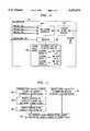
- FIG. 1is a block diagram of a prior art communication system 400 topology which provides data and voice/video communications to and from a plurality of endpoint devices using IsoEthernet communication protocols.
- the endpoint devicesare provided in the form of work stations 411.
- Each work station 411includes telephone equipment 401 and a personal computer 403.
- the term "telephone"is to include any real-time communications functions such as voice, video, or conference control and data.
- the telephone equipment 401 included in a specific work station 411connects to a B-Channel trunk providing a dedicated set of 96 B-Channels.
- each work station 411is provided with a separate, dedicated B-Channel trunk, such as a first set of 96 B-Channels 402, a second set of 96 B-Channels 405, or a third set of 96 B-Channels 408.
- a separate, dedicated B-Channel trunksuch as a first set of 96 B-Channels 402, a second set of 96 B-Channels 405, or a third set of 96 B-Channels 408.
- the first set of 96 B-Channels 402is coupled to a multiplexer/demultiplexer (MUX/DEMUX) 447.
- MUX/DEMUXmultiplexer/demultiplexer
- the second set of 96 B-Channels 405 and the third set of 96 B-Channelsare each coupled to corresponding MUX/DEMUX 447.
- Each MUX/DEMUX 447combines a set of 96 B-Channels with a 10 Mb/sec Ethernet channel.
- the first set of 96 B-Channels 402is combined with Ethernet Channel 404
- the second set of 96 B-Channels 405is combined with Ethernet Channel 407
- the third set of 96 B-Channels 408is combined with Ethernet Channel 410.
- Each MUX/DEMUX 447combines an Ethernet channel and a set of 96 B-Channels to provide a 16 Mb/sec IsoEthernet channel 409 from the work station to the serving closet.
- the same (symmetric) functionis also provided from the closet to the work station.
- the IsoEthernet channels 409are routed to a serving closet 475, which may be situated in a remote location with respect to work stations 411.
- a demultiplexer (MUX/DEMUX) 477is applied to each 16 Mb/sec IsoEthernet channel 409 to separate the IsoEthernet channel 409 into a 10 Mb/sec Ethernet channel and a B-Channel set of 96 B-Channels.
- the 10 Mb/sec Ethernet channelsare routed to an Ethernet hub 415, and the B-Channel sets are routed to a TDM bus 423.
- the Ethernet hubmay typically be a classical multiport repeater or a LAN switch.
- TDM bus 423is controlled by a TDM system controller 417 which implements time-division multiplexing.
- the operational speed of TDM system controller 417is determined by the number of work stations 411 and/or quantity of telephone equipment 401 utilized in a given communications system. For example, in the system of FIG. 1, three work stations 411 are shown, each requiring a dedicated set of 96 B-Channels. Each set of B-Channels operates at approximately 6 Mb/sec, and the TDM system controller 417 must be equipped to switch three sets of B-Channels. Therefore, the TDM system controller 417 must have a switching speed of 18 Mb/sec. If twelve work stations 411 were present, the required switching speed would be 72 Mb/sec. Using current state-of-the-art technology, a 72-mHz switch is significantly more costly than an otherwise comparable 6-mHz switch.
- the TDM system controller 417is coupled to a digital trunk interface module 419 which interfaces the TDM system controller 417 with a conventional telephone system switch 449.
- the digital trunk interface module 419communicates with the conventional telephone system switch 449 using a standard protocol such as PRI (Primary Rate Interface), BRI (Basic Rate Interface), T1, E1, DS3, or the like.
- PRIPrimary Rate Interface
- BRIBasic Rate Interface
- T1, E1, DS3, or the likeEach personal computer 403 is connected to a corresponding Ethernet channel, such as Ethernet channel 404.
- Ethernet channel 407, or Ethernet channel 410Each Ethernet channel 404, 407, 410 is routed to a corresponding MUX/DEMUX 447.
- Communications systems and methodsare directed to a novel communications platform which employs a TDM bus, a TDM bus controller, and an Ethernet hub.
- the Ethernet hubincludes a plurality of communication ports and a centralized passive bus controller to provide for the communication of data, voice, and/or video signals among a plurality of endpoint devices.
- the TDM bus controllerprovides a plurality of B-Channels on the TDM bus.
- the centralized passive bus controlleris coupled to the TDM bus controller via a control link.
- Each endpoint deviceis connected to at least one of the Ethernet hub communication ports and the TDM bus.
- the Ethernet hubdynamically allocates one or more individual B-Channels of a single B-Channel set amongst a group of endpoint devices, such as telephone equipment, video communications equipment, processors, and/or computing devices.
- the centralized Ethernet hubprovides a logical control channel to each endpoint device for call establishment.
- Each endpoint deviceis coupled to the logical control channel over at least one of a first path comprising the Ethernet hub and a second path comprising the TDM bus, the TDM bus controller, and the control link.
- the logical control channelexecutes B-channel seizure algorithms for establishment of communications to and from selected endpoint devices.
- FIG. 1is a block diagram of a prior art communication system topology which provides data and voice/video communications to and from a plurality of endpoint devices using IsoEthernet communication protocols;
- FIG. 2is a block diagram showing the novel communications platform of the present invention
- FIG. 3is a hardware block diagram setting forth the structure of the centralized Ethernet hub shown in FIG. 2;
- FIG. 4is a hardware block diagram setting forth the structure of the TDM bus controller shown in FIG. 2;
- FIG. 5is a flowchart setting forth the sequence of operations implemented by the system of FIG. 2 when an endpoint device initiates a communications link according to a first embodiment disclosed herein.
- FIG. 2illustrates a novel communications system 500 which provides for the communication of data, voice and/or video signals among a plurality of endpoint devices such as telephone equipment 401, personal computer 403, video communications equipment 434, voice/video terminal 436, data terminal 438, or the like.
- the communications system 500includes a TDM bus 459, a TDM bus controller 461, a passive Ethernet bus 451, and a centralized Ethernet hub 463.
- the TDM bus controller 461provides a single B-Channel set, consisting of a plurality of B-Channels, on TDM bus 459.
- the centralized Ethernet hub 463is coupled to the TDM bus controller 461 via a control link 465.
- Each endpoint deviceis coupled to at least one of the passive Ethernet bus 451 and the TDM bus 459.
- the endpoint devicemay be directly coupled to the TDM bus 459 as in the case of video communications equipment 434.
- endpoint devicesmay be coupled to TDM bus 459 and/or Ethernet bus 451 via MUX/DEMUXes 480 and communication links 482, as, for example, where the endpoint device is a work station 411.
- the centralized Ethernet hub 463operates over the passive Ethernet bus 451 to dynamically allocate one or more individual B-Channels of the single B-Channel set amongst a group of endpoint devices.
- the centralized Ethernet hub 463provides a logical control channel originating from the TDM bus controller 461 and terminating at each endpoint device for call establishment.
- Each endpoint deviceis coupled to the logical control channel over at least one of a first path comprising the passive Ethernet bus 451 and a second path comprising the TDM bus 459, the TDM bus controller 461, and the control link 465.
- the logical control channelexecutes B-channel seizure algorithms for establishment of communications to and from selected endpoint devices. In this manner, a single set of B-Channels is dynamically allocated amongst a group of endpoint devices such as telephone equipment 401, personal computer 403, video communications equipment 434, voice/video terminal 436, and data terminal 438.
- the endpoint devicesmay be arranged to provide one or more work stations 411.
- a typical work station 411may include, for example, telephone equipment 401 and personal computer 403.
- Passive Ethernet bus 451may be a conventional passive 10 Mb/sec Ethernet bus.
- TDM bus controller 461may be a conventional time division multiplexer operating, for example, at 6 Mb/sec to provide a shared set of 96 standard B-Channels. In this manner, 96 such B-Channels comprise a set. However, this example is presented for purposes of illustration, to match that set forth under the IsoEthernet draft standard, inasmuch as a set of B-Channels may be configured to contain any convenient number of B-Channels to meet the needs of specific system applications.
- TDM bus controller 461can be configured to provide an optional D-Channel. Conventional devices are utilized to provide control link 465 and TDM bus 459. The structure and function of these devices are well-known to those skilled in the art.
- Centralized Ethernet hub 463provides timing and/or synchronization information to the TDM bus 459 over control link 465, as well as one or more electrical termination loads for the passive Ethernet bus 451.
- Each passive Ethernet bus 451terminates on one port of a traditional multiport repeater or LAN switch.
- the combination of TDM bus controller 461, control link 465, and centralized Ethernet hub 463is conceptualized as being a hybrid Ethernet repeater which provides the logical equivalent of a passive bus for the plurality of communications trunks, such as the TDM bus 459, for connection to endpoint devices such as work station 411, telephone equipment 401, video communications equipment 434, and/or personal computer 403.
- Work station 411may include a voice/video terminal 436 and a data terminal 438.
- the data terminal 438is equipped to operate over an Ethernet communications channel of 10 Mb/sec, and the voice/video terminal 436 operates using a real-time communications channel consisting of some number of B-Channels, typically 2, 6, or 24.
- Centralized Ethernet hub 463, TDM bus controller 461, conventional telephone system switch 449, and one or more MUX/DEMUXes 480may be collectively referred to as closet equipment 484.
- Each endpoint device connected to TDM bus 459is equipped to capture any of the 96 B-Channels, and these channels are shared among the various endpoint devices.
- Control softwareis distributed amongst the endpoint devices to provide an endpoint-to-endpoint communications structure that does not requires traditional telephony switching elements. This control software is transmitted from one or more endpoint devices to centralized Ethernet hub 463 over passive Ethernet bus 451, to the TDM bus controller 461 via control link 465 where the software is utilized to provide the logical control channel referred to previously. Alternatively, all or a portion of the control software may reside in the TDM bus controller 461.
- the control software executed by TDM bus controller 461implements selective, dynamic allocation of the B-Channels to enable communications system 500 to adapt to changing user needs.
- Selective, dynamic channel allocationmeans that at least some of the B-Channels are not dedicated to one or more specific uses.
- These B-Channelsare shared amongst the endpoint devices, based upon demand resulting from the endpoint devices in use at a particular point in time. As new devices are activated, B-Channels may be allocated away from devices presently in use. If a device presently in use is deactivated, the B-Channels occupied by this device may be reallocated to one or more devices that continue to communicate over the TDM bus 459 and/or the passive Ethernet bus 451.
- One example of selective, dynamic B-Channel allocationis in the operational environment of a small business having 10 work stations. In this business, it is expected that no more than four video telephone calls will be under way at any given time. Each video call requires a communications channel providing a data rate of 384 Kb/sec to provide a video image of satisfactory quality. This data rate may be provided using 6 B-Channels, where each B-Channel provides a data rate of 64 Kb/sec. To provide the business with four video communications channels, 24 B-Channels are required.
- the two vacant channelscould both be assigned to the higher-priority telephone to triple the available data rate on this telephone to 1152 Kb/sec.
- the capability of allocating the B-Channels to meet the needs of specific situations and system requirementsmay be referred to as selective, dynamic channel allocation. This function is performed using software stored in and executed by one or more endpoint devices in conjunction with software executed within the TDM bus controller 461. This software is generally available and known to those skilled in the art.
- the system of FIG. 2is advantageous over the prior art system shown in FIG. 1, in that a simpler, less expensive TDM bus controller may be employed in the system of FIG. 2.
- the endpoint devicesare conventional voice telephones.
- the TDM system controller 417 of FIG. 1must provide eight sets of 96 B-Channels, one set for each telephone.
- the TDM system controller 417must be capable of operating at a speed of [6 Mb/sec (one set of B-channels)*8 (number of B-Channel sets to be provided)], or 48 Mb/sec.
- the cost of a 48 Mb/sec TDM system controller 417(which contains 48 mHz switching devices) is relatively high.
- the eight voice telephones discussed in the example described abovewould share a common B-Channel set.
- the TDM bus controller 461would thus be required to operate at a relatively low speed of 6 Mb/sec, a significant cost savings over a 48 Mb/sec TDM system controller 417.
- the centralized Ethernet hub 463provides for electronic communication over an Ethernet bus 451 using a traditional Ethernet multiport repeater or LAN switch 367. These multiport repeaters and LAN switches are well-known to those skilled in the art.
- Multiport repeater or LAN switch 463generally includes a control link 465 port which controls the switching functions of the multiport repeater or LAN switch.
- Ethernet endpoint devicesmay or may not be equipped to communicate over B-Channels and/or D-Channels.
- the signals communicated over passive Ethernet bus 451utilize a data structure consisting of a data header 319 followed by data 321.
- the data header 319includes a terminal endpoint identifier (TID) 317 which uniquely identifies a specific endpoint device and/or a certain category of endpoint device such as voice telephone, personal computer, etc.
- TIDterminal endpoint identifier
- the information within the TID 317 portion of the data header 319, as well as the general use of TIDs,is well-known to those skilled in the art.
- FIG. 4is a detailed hardware block diagram of the TDM bus controller 461 shown in FIG. 2.
- TDM bus 459is coupled to a time-division multiplexer 803 adapted to provide a plurality of bandwidth-limited communication channels in a time-division multiplexed arrangement.
- time-division multiplexer 803provides 96 standard B-Channels occupying a total bandwidth of 6 Mb/sec.
- One or more of these communication channelsmay be interfaced with a conventional telephone line 815 using a telephone system interface 805.
- Telephone system interface 805converts the conventional TDM signals produced by time-division multiplexer 803 into a form suitable for transmission over one or more standard tip/ring telephone lines.
- Time-division multiplexer 803is controlled by a processor 807 which may be a commonly-available microprocessor device of a type well-known to those skilled in the art.
- the processor 807interfaces with centralized Ethernet hub 463 (FIG. 3) over control link 465 (FIG. 4).
- Processor 807is coupled to a standard random-access memory (RAM) 809 device.
- a B-Channel Time Slot Allocation Table 811is stored in RAM 809.
- Allocation Table 811associates a list of endpoint devices with corresponding time slots. Each time slot specifies one or more communication channels provided by time-division multiplexer 803. For example, endpoint device "A" is associated with time slots 1, 2, and 4. Time slots 1, 2, and 4 may correspond to B-Channels 1, 2, and 4 of a single B-Channel set of 96 B-Channels.
- FIG. 5is a flowchart setting forth the operational sequence which commences at the time a first endpoint device seeks to establish a new communications link with a second endpoint device.
- an endpoint device coupled to the passive Ethernet businitiates a B-Channel request.
- the requestis transmitted to the centralized Ethernet hub 463 over the passive Ethernet channel (block 603).
- the requestis conveyed to the TDM bus controller over control link 465 (FIG. 4).
- the TDM bus controllerassigns the maximum possible number of requested but vacant (unoccupied) B-Channels to the endpoint device (FIG. 5, block 607).
- FIG. 5also describes the operational sequence implemented when an endpoint device coupled to the TDM bus seeks to initiate communications. Operations commence at block 609, at which point the endpoint device initiates a B-Channel allocation request over a standard D-Channel provided by TDM bus controller 461 (FIG. 2). In response to the allocation request, the TDM bus controller assigns the maximum possible number of requested but vacant (unoccupied) B-Channels to the endpoint device (FIG. 5, block 607).
Landscapes
- Engineering & Computer Science (AREA)
- Computer Networks & Wireless Communication (AREA)
- Signal Processing (AREA)
- Use Of Switch Circuits For Exchanges And Methods Of Control Of Multiplex Exchanges (AREA)
- Small-Scale Networks (AREA)
- Telephonic Communication Services (AREA)
- Data Exchanges In Wide-Area Networks (AREA)
- Time-Division Multiplex Systems (AREA)
Abstract
Description
Claims (18)
Priority Applications (5)
| Application Number | Priority Date | Filing Date | Title |
|---|---|---|---|
| US08/323,184US5553071A (en) | 1994-10-14 | 1994-10-14 | Communication system topology providing dynamic allocation of B-channels |
| CA002157529ACA2157529C (en) | 1994-10-14 | 1995-09-05 | Communication system topology providing dynamic allocation of b-channels |
| EP95307026AEP0707432B1 (en) | 1994-10-14 | 1995-10-03 | Communication system topology providing dynamic allocation of B-channels |
| DE69534969TDE69534969T2 (en) | 1994-10-14 | 1995-10-03 | Topology of a transmission system for providing dynamic allocation of B-channels |
| JP26504795AJP3865805B2 (en) | 1994-10-14 | 1995-10-13 | Communication system topology providing dynamic allocation of B-channels |
Applications Claiming Priority (1)
| Application Number | Priority Date | Filing Date | Title |
|---|---|---|---|
| US08/323,184US5553071A (en) | 1994-10-14 | 1994-10-14 | Communication system topology providing dynamic allocation of B-channels |
Publications (1)
| Publication Number | Publication Date |
|---|---|
| US5553071Atrue US5553071A (en) | 1996-09-03 |
Family
ID=23258082
Family Applications (1)
| Application Number | Title | Priority Date | Filing Date |
|---|---|---|---|
| US08/323,184Expired - LifetimeUS5553071A (en) | 1994-10-14 | 1994-10-14 | Communication system topology providing dynamic allocation of B-channels |
Country Status (5)
| Country | Link |
|---|---|
| US (1) | US5553071A (en) |
| EP (1) | EP0707432B1 (en) |
| JP (1) | JP3865805B2 (en) |
| CA (1) | CA2157529C (en) |
| DE (1) | DE69534969T2 (en) |
Cited By (26)
| Publication number | Priority date | Publication date | Assignee | Title |
|---|---|---|---|---|
| US5710882A (en)* | 1995-06-29 | 1998-01-20 | Telefonaktiebolaget Lm Ericsson | Method and call set up server for setting up a call using a call handling portion and a connection handling portion to handle the call and the connection, respectively |
| US5761430A (en)* | 1996-04-12 | 1998-06-02 | Peak Audio, Inc. | Media access control for isochronous data packets in carrier sensing multiple access systems |
| WO1998034379A1 (en)* | 1997-02-03 | 1998-08-06 | Reltec Corporation | Distributed ethernet hub |
| US5805597A (en)* | 1996-06-04 | 1998-09-08 | National Semiconductor Corporation | Method and apparatus for providing low power basic telephony type service over a twisted pair ethernet physical layer |
| US5896508A (en)* | 1995-02-23 | 1999-04-20 | Advanced Micro Devices, Inc. | Hub-network adapter device for a file server personal computer |
| US5978876A (en)* | 1997-04-14 | 1999-11-02 | Play, Inc. | System and method for controlling communications between subsystems |
| US6061348A (en)* | 1995-12-22 | 2000-05-09 | Cisco Technology, Inc. | Method and apparatus for dynamically allocating bandwidth for a time division multiplexed data bus |
| US6115374A (en)* | 1995-12-22 | 2000-09-05 | Cisco Technology, Inc. | Method and apparatus for dynamically assigning bandwidth for a time division multiplexing data bus |
| US6169928B1 (en) | 1998-06-30 | 2001-01-02 | Ge Fanuc Automation North America, Inc. | Apparatus and method for sharing data among a plurality of control devices on a communications network |
| US6330632B1 (en)* | 1998-09-30 | 2001-12-11 | Hewlett-Packard Company | System for arbitrating access from multiple requestors to multiple shared resources over a shared communications link and giving preference for accessing idle shared resources |
| US6339584B1 (en) | 1996-04-12 | 2002-01-15 | Cirrus Logic, Inc. | Media access control for isochronous data packets in carrier sensing multiple access systems |
| US20020159438A1 (en)* | 2001-04-25 | 2002-10-31 | Mark Rumer | Ethernet based TDM switch |
| US20020163921A1 (en)* | 1999-06-03 | 2002-11-07 | Ethridge Barry J. | Distributed ethernet hub |
| US6493335B1 (en)* | 1996-09-24 | 2002-12-10 | At&T Corp. | Method and system for providing low-cost high-speed data services |
| US6591422B1 (en)* | 1997-09-23 | 2003-07-08 | Alcatel | Facility for assigning transmission channels to terminals of a service-on-demand system |
| US6678282B2 (en)* | 1996-10-23 | 2004-01-13 | Cisco Technology, Inc. | System and method for communicating packetized data over a channel bank |
| US20040076191A1 (en)* | 2000-12-22 | 2004-04-22 | Jim Sundqvist | Method and a communiction apparatus in a communication system |
| US6781956B1 (en) | 1999-09-17 | 2004-08-24 | Cisco Technology, Inc. | System and method for prioritizing packetized data from a distributed control environment for transmission through a high bandwidth link |
| US20050041692A1 (en)* | 2003-08-22 | 2005-02-24 | Thomas Kallstenius | Remote synchronization in packet-switched networks |
| US6970433B1 (en)* | 1996-04-29 | 2005-11-29 | Tellabs Operations, Inc. | Multichannel ring and star networks with limited channel conversion |
| US20060088000A1 (en)* | 2004-10-27 | 2006-04-27 | Hans Hannu | Terminal having plural playback pointers for jitter buffer |
| US7099276B1 (en)* | 1999-05-24 | 2006-08-29 | Broadcom Corporation | Apparatus and method for distributing a load across a trunk group |
| US20060230179A1 (en)* | 2001-02-16 | 2006-10-12 | Nonend Inventions N.V. | Organic data network having a dynamic topology |
| US20100158525A1 (en)* | 2008-12-19 | 2010-06-24 | Edward Walter | Modular network terminals and methods to use the same |
| US7978689B1 (en)* | 2002-06-24 | 2011-07-12 | At&T Intellectual Property I, L.P. | Apparatus, system and method for transmitting voice and data over ethernet |
| US20120297451A1 (en)* | 2011-05-16 | 2012-11-22 | Cocomo, Inc. | Communications system |
Families Citing this family (6)
| Publication number | Priority date | Publication date | Assignee | Title |
|---|---|---|---|---|
| CA2173027C (en)* | 1996-03-29 | 2003-09-16 | Evan Mcintosh | Merged telephone and data system |
| US5982767A (en)* | 1996-05-30 | 1999-11-09 | Mitel Corporation | Merged telephone and data network |
| FI980382A7 (en)* | 1998-02-19 | 1999-08-20 | Nokia Corp | Telecommunications system and method for arranging an ISDN exchange connection |
| US6215789B1 (en) | 1998-06-10 | 2001-04-10 | Merlot Communications | Local area network for the transmission and control of audio, video, and computer data |
| JP2000032013A (en) | 1998-07-15 | 2000-01-28 | Oki Electric Ind Co Ltd | Data transmission system |
| US6918001B2 (en)* | 2002-01-02 | 2005-07-12 | Intel Corporation | Point-to-point busing and arrangement |
Citations (4)
| Publication number | Priority date | Publication date | Assignee | Title |
|---|---|---|---|---|
| US5249183A (en)* | 1991-03-14 | 1993-09-28 | Level One Communications, Inc. | Interfacing unit for local area networks |
| US5305318A (en)* | 1990-11-09 | 1994-04-19 | Ricoh Company, Ltd. | Method for controlling data transmission of an integrated services digital network terminal having a multi-channel data transmission capability |
| US5307347A (en)* | 1992-04-10 | 1994-04-26 | International Business Machines Corporation | Method and apparatus for sharing a telecommunications channel among multiple users |
| US5331316A (en)* | 1989-06-23 | 1994-07-19 | Alcatel N.V. | Communication system including allocating free signalling channels to individual substations having data to transmit |
Family Cites Families (2)
| Publication number | Priority date | Publication date | Assignee | Title |
|---|---|---|---|---|
| US5361261A (en)* | 1992-11-02 | 1994-11-01 | National Semiconductor Corporation | Frame-based transmission of data |
| US5355375A (en)* | 1993-03-18 | 1994-10-11 | Network Systems Corporation | Hub controller for providing deterministic access to CSMA local area network |
- 1994
- 1994-10-14USUS08/323,184patent/US5553071A/ennot_activeExpired - Lifetime
- 1995
- 1995-09-05CACA002157529Apatent/CA2157529C/ennot_activeExpired - Fee Related
- 1995-10-03EPEP95307026Apatent/EP0707432B1/ennot_activeExpired - Lifetime
- 1995-10-03DEDE69534969Tpatent/DE69534969T2/ennot_activeExpired - Lifetime
- 1995-10-13JPJP26504795Apatent/JP3865805B2/ennot_activeExpired - Fee Related
Patent Citations (4)
| Publication number | Priority date | Publication date | Assignee | Title |
|---|---|---|---|---|
| US5331316A (en)* | 1989-06-23 | 1994-07-19 | Alcatel N.V. | Communication system including allocating free signalling channels to individual substations having data to transmit |
| US5305318A (en)* | 1990-11-09 | 1994-04-19 | Ricoh Company, Ltd. | Method for controlling data transmission of an integrated services digital network terminal having a multi-channel data transmission capability |
| US5249183A (en)* | 1991-03-14 | 1993-09-28 | Level One Communications, Inc. | Interfacing unit for local area networks |
| US5307347A (en)* | 1992-04-10 | 1994-04-26 | International Business Machines Corporation | Method and apparatus for sharing a telecommunications channel among multiple users |
Non-Patent Citations (2)
| Title |
|---|
| "IEEE Standards for Local & Metropolitan Area Networks--Integrated Services (IS) LAN: IEEE 802.9 Isochronous services with Carrier sense multiple access with collison detection (CSMA/CD) Media access control (MAC) service;" IEEE 802.9a Draft Standard P.802.9a/D3, Jan. 16, 1994; by IEEE 802.9a Editor; IEEE Standards Department, Copyright and Permissions, 445 Hoes Lane, P.O. Box 1331, Piscataway, NJ 08855-1331, USA. |
| IEEE Standards for Local & Metropolitan Area Networks Integrated Services (IS) LAN: IEEE 802.9 Isochronous services with Carrier sense multiple access with collison detection (CSMA/CD) Media access control (MAC) service; IEEE 802.9a Draft Standard P.802.9a/D3, Jan. 16, 1994; by IEEE 802.9a Editor; IEEE Standards Department, Copyright and Permissions, 445 Hoes Lane, P.O. Box 1331, Piscataway, NJ 08855 1331, USA.* |
Cited By (56)
| Publication number | Priority date | Publication date | Assignee | Title |
|---|---|---|---|---|
| US5896508A (en)* | 1995-02-23 | 1999-04-20 | Advanced Micro Devices, Inc. | Hub-network adapter device for a file server personal computer |
| US5710882A (en)* | 1995-06-29 | 1998-01-20 | Telefonaktiebolaget Lm Ericsson | Method and call set up server for setting up a call using a call handling portion and a connection handling portion to handle the call and the connection, respectively |
| US6115374A (en)* | 1995-12-22 | 2000-09-05 | Cisco Technology, Inc. | Method and apparatus for dynamically assigning bandwidth for a time division multiplexing data bus |
| US6061348A (en)* | 1995-12-22 | 2000-05-09 | Cisco Technology, Inc. | Method and apparatus for dynamically allocating bandwidth for a time division multiplexed data bus |
| US5761430A (en)* | 1996-04-12 | 1998-06-02 | Peak Audio, Inc. | Media access control for isochronous data packets in carrier sensing multiple access systems |
| US6339584B1 (en) | 1996-04-12 | 2002-01-15 | Cirrus Logic, Inc. | Media access control for isochronous data packets in carrier sensing multiple access systems |
| US6161138A (en)* | 1996-04-12 | 2000-12-12 | Peak Audio, Inc. | Media access control for isochronous data packets in carrier sensing multiple access systems |
| US20100054263A1 (en)* | 1996-04-29 | 2010-03-04 | Tellabs Operations, Inc. | Multichannel ring and star networks with limited channel conversion |
| US6970433B1 (en)* | 1996-04-29 | 2005-11-29 | Tellabs Operations, Inc. | Multichannel ring and star networks with limited channel conversion |
| US7606180B2 (en) | 1996-04-29 | 2009-10-20 | Tellabs Operations, Inc. | Multichannel ring and star networks with limited channel conversion |
| US8134939B2 (en) | 1996-04-29 | 2012-03-13 | Tellabs Operations, Inc. | Multichannel ring and star networks with limited channel conversion |
| US5805597A (en)* | 1996-06-04 | 1998-09-08 | National Semiconductor Corporation | Method and apparatus for providing low power basic telephony type service over a twisted pair ethernet physical layer |
| US6493335B1 (en)* | 1996-09-24 | 2002-12-10 | At&T Corp. | Method and system for providing low-cost high-speed data services |
| US6678282B2 (en)* | 1996-10-23 | 2004-01-13 | Cisco Technology, Inc. | System and method for communicating packetized data over a channel bank |
| US6466572B1 (en) | 1997-02-03 | 2002-10-15 | Marconi Communications, Inc. | Distributed ethernet hub |
| WO1998034379A1 (en)* | 1997-02-03 | 1998-08-06 | Reltec Corporation | Distributed ethernet hub |
| US5978876A (en)* | 1997-04-14 | 1999-11-02 | Play, Inc. | System and method for controlling communications between subsystems |
| US6591422B1 (en)* | 1997-09-23 | 2003-07-08 | Alcatel | Facility for assigning transmission channels to terminals of a service-on-demand system |
| US6169928B1 (en) | 1998-06-30 | 2001-01-02 | Ge Fanuc Automation North America, Inc. | Apparatus and method for sharing data among a plurality of control devices on a communications network |
| US6330632B1 (en)* | 1998-09-30 | 2001-12-11 | Hewlett-Packard Company | System for arbitrating access from multiple requestors to multiple shared resources over a shared communications link and giving preference for accessing idle shared resources |
| US7099276B1 (en)* | 1999-05-24 | 2006-08-29 | Broadcom Corporation | Apparatus and method for distributing a load across a trunk group |
| US20020163921A1 (en)* | 1999-06-03 | 2002-11-07 | Ethridge Barry J. | Distributed ethernet hub |
| US7356042B2 (en) | 1999-06-03 | 2008-04-08 | Tellabs Beford, Inc. | Distributed ethernet hub |
| US6781956B1 (en) | 1999-09-17 | 2004-08-24 | Cisco Technology, Inc. | System and method for prioritizing packetized data from a distributed control environment for transmission through a high bandwidth link |
| US7489636B1 (en) | 1999-09-17 | 2009-02-10 | Cisco Technology, Inc. | System and method for prioritizing packetized data from distributed control environment for transmission through a high bandwidth link |
| US20040076191A1 (en)* | 2000-12-22 | 2004-04-22 | Jim Sundqvist | Method and a communiction apparatus in a communication system |
| US7450601B2 (en) | 2000-12-22 | 2008-11-11 | Telefonaktiebolaget Lm Ericsson (Publ) | Method and communication apparatus for controlling a jitter buffer |
| US20070220117A1 (en)* | 2001-02-16 | 2007-09-20 | Nonend Inventions N.V. | Distribution of Streaming Content Between Media Players Configured to Locate Each Other |
| US8099513B2 (en) | 2001-02-16 | 2012-01-17 | Nonend Inventions N.V. | Streaming content from one or more production nodes or media player systems |
| US20070220130A1 (en)* | 2001-02-16 | 2007-09-20 | Nonend Inventions N.V. | Traffic Information System for Vehicles Using Wireless Peer to Peer (P2P) Connections |
| US20080022006A1 (en)* | 2001-02-16 | 2008-01-24 | Nonend Inventions N.V. | Using Content on a Media Player and Streaming the Same Content to One or More Media Players |
| US7349984B2 (en)* | 2001-02-16 | 2008-03-25 | Nonend Inventions N.V. | Receiver driven media streaming in a network node |
| US7349983B2 (en)* | 2001-02-16 | 2008-03-25 | Nonend Inventions N.V. | Receiver driven distribution of data using address data of a peer node |
| US20060242224A1 (en)* | 2001-02-16 | 2006-10-26 | Nonend Inventions N.V. | Organic data network having a dynamic topology |
| US9531770B2 (en) | 2001-02-16 | 2016-12-27 | Nonend Inventions N.V. | Distribution of streaming content between media players configured to locate each other |
| US20060230179A1 (en)* | 2001-02-16 | 2006-10-12 | Nonend Inventions N.V. | Organic data network having a dynamic topology |
| US8266315B2 (en) | 2001-02-16 | 2012-09-11 | Nonend Inventions N.V. | Streaming content from a production node and a consumer node |
| US7522993B2 (en) | 2001-02-16 | 2009-04-21 | Nonend Inventions N.V. | Traffic information system for vehicles using wireless peer to peer (P2P) connections |
| US7587508B2 (en) | 2001-02-16 | 2009-09-08 | Nonend Inventions, N.V. | Multiple source receiver-driven streaming of content between peers |
| US7590752B2 (en) | 2001-02-16 | 2009-09-15 | Nonend Inventions, N.V. | Playing media content on a media player while streaming the retrieved parts of the media content to other devices |
| US20070118591A1 (en)* | 2001-02-16 | 2007-05-24 | Nonend Inventions N.V. | Receiver-Driven Multi-Source Streaming of Content |
| US8090862B2 (en) | 2001-02-16 | 2012-01-03 | Nonend Inventions N.V. | Initiating an alternative communication channel for receiving streaming content |
| US20110138068A1 (en)* | 2001-02-16 | 2011-06-09 | Nonend Inventions N.V. | Initiating an alternative communication channel for receiving streaming content |
| US7779138B2 (en) | 2001-02-16 | 2010-08-17 | Nonend Inventions N.V. | Streaming content between media players configured to locate each other |
| US20110004696A1 (en)* | 2001-02-16 | 2011-01-06 | Nonend Inventions Nv | Distribution of Streaming Content Between Media Players Configured to Locate Each Other |
| US6999450B2 (en)* | 2001-04-25 | 2006-02-14 | Occam Networks | Ethernet based TDM switch |
| US20020159438A1 (en)* | 2001-04-25 | 2002-10-31 | Mark Rumer | Ethernet based TDM switch |
| US7978689B1 (en)* | 2002-06-24 | 2011-07-12 | At&T Intellectual Property I, L.P. | Apparatus, system and method for transmitting voice and data over ethernet |
| US20050041692A1 (en)* | 2003-08-22 | 2005-02-24 | Thomas Kallstenius | Remote synchronization in packet-switched networks |
| US7415044B2 (en) | 2003-08-22 | 2008-08-19 | Telefonaktiebolaget Lm Ericsson (Publ) | Remote synchronization in packet-switched networks |
| US7970020B2 (en) | 2004-10-27 | 2011-06-28 | Telefonaktiebolaget Lm Ericsson (Publ) | Terminal having plural playback pointers for jitter buffer |
| US20060088000A1 (en)* | 2004-10-27 | 2006-04-27 | Hans Hannu | Terminal having plural playback pointers for jitter buffer |
| US20100158525A1 (en)* | 2008-12-19 | 2010-06-24 | Edward Walter | Modular network terminals and methods to use the same |
| US8903244B2 (en) | 2008-12-19 | 2014-12-02 | At&T Intellectual Property I., L.P. | Modular network terminals and methods to use the same |
| US20120297451A1 (en)* | 2011-05-16 | 2012-11-22 | Cocomo, Inc. | Communications system |
| US9210143B2 (en)* | 2011-05-16 | 2015-12-08 | Talko Inc. | Communications system |
Also Published As
| Publication number | Publication date |
|---|---|
| CA2157529A1 (en) | 1996-04-15 |
| JPH08214060A (en) | 1996-08-20 |
| DE69534969T2 (en) | 2007-01-04 |
| DE69534969D1 (en) | 2006-06-08 |
| JP3865805B2 (en) | 2007-01-10 |
| EP0707432B1 (en) | 2006-05-03 |
| EP0707432A3 (en) | 1998-11-04 |
| EP0707432A2 (en) | 1996-04-17 |
| CA2157529C (en) | 2000-01-11 |
Similar Documents
| Publication | Publication Date | Title |
|---|---|---|
| US5553071A (en) | Communication system topology providing dynamic allocation of B-channels | |
| US5757781A (en) | Dynamic insertion and removal of multi-media call-handling resources into/from video calls to provide calling features | |
| US5051982A (en) | Methods and apparatus for implementing switched virtual connections (SVCs) in a digital communications switching system | |
| US4700340A (en) | Method and apparatus for providing variable reliability in a telecommunication switching system | |
| US8144729B2 (en) | Systems and methods for multiple mode voice and data communications using intelligently bridged TDM and packet buses | |
| US4866703A (en) | Integrated services digital network module | |
| EP0863679B1 (en) | Method and device for centralised call handling | |
| JPH10271136A (en) | Method and system for asynchronous transfer mode integrated access service | |
| US6563817B1 (en) | Communication system | |
| JP2001044961A (en) | Time division multiplexing device | |
| US4689788A (en) | Method and apparatus for implementing a cost efficient voice/data communication system with a conventional PBX switch | |
| EP0983693B1 (en) | Control of communication traffic | |
| US7460530B2 (en) | Subscriber card, a subscriber unit, and an exchange for concentrating internet frames | |
| US7277534B1 (en) | Communications system and method | |
| KR100244777B1 (en) | Application of Version 5.2 Protocol to Wireless Subscriber Network | |
| JP2567878B2 (en) | Relay line connection control method | |
| JPH09130429A (en) | Communications system | |
| US7177305B2 (en) | Inter-switch telecommunications system for interconnecting packet-capable Time Division Multiplexed switches with non-packet-capable Time Division Multiplexed switches via an asynchronous transfer mode network | |
| JP3324510B2 (en) | ISDN bearer channel distribution system | |
| GB2326562A (en) | ISDN feature phones | |
| GB2318261A (en) | Concentrating transmultiplexer for cable telephony | |
| JP3033038B2 (en) | ISDN terminal accommodation equipment for leased line | |
| Ryva et al. | Corporate networking: evolution and architecture | |
| JPH0435438A (en) | Packet exchange system | |
| JPH057194A (en) | Common interface controller for isdn |
Legal Events
| Date | Code | Title | Description |
|---|---|---|---|
| AS | Assignment | Owner name:AT&T CORP., NEW YORK Free format text:ASSIGNMENT OF ASSIGNORS INTEREST;ASSIGNORS:ARANGUREN, WILLIAM L.;BAKER, ALBERT D.;REEL/FRAME:007192/0065 Effective date:19941014 | |
| AS | Assignment | Owner name:AT&T IPM CORP., FLORIDA Free format text:ASSIGNMENT OF ASSIGNORS INTEREST;ASSIGNOR:AT&T CORP.;REEL/FRAME:007467/0511 Effective date:19950428 | |
| STCF | Information on status: patent grant | Free format text:PATENTED CASE | |
| AS | Assignment | Owner name:LUCENT TECHNOLOGIES INC., NEW JERSEY Free format text:ASSIGNMENT OF ASSIGNORS INTEREST;ASSIGNOR:AT&T CORP.;REEL/FRAME:008179/0675 Effective date:19960329 | |
| FEPP | Fee payment procedure | Free format text:PAYOR NUMBER ASSIGNED (ORIGINAL EVENT CODE: ASPN); ENTITY STATUS OF PATENT OWNER: LARGE ENTITY | |
| FPAY | Fee payment | Year of fee payment:4 | |
| AS | Assignment | Owner name:LUCENT TECHNOLOGIES, INC., NEW JERSEY Free format text:ASSIGNMENT OF ASSIGNORS INTEREST;ASSIGNOR:AT&T CORP.;REEL/FRAME:012754/0365 Effective date:19960329 Owner name:AVAYA TECHNOLOGY CORP., NEW JERSEY Free format text:ASSIGNMENT OF ASSIGNORS INTEREST;ASSIGNOR:LUCENT TECHNOLOGIES INC.;REEL/FRAME:012754/0770 Effective date:20000929 | |
| AS | Assignment | Owner name:BANK OF NEW YORK, THE, NEW YORK Free format text:SECURITY AGREEMENT;ASSIGNOR:AVAYA TECHNOLOGY CORP.;REEL/FRAME:012775/0144 Effective date:20020405 | |
| FPAY | Fee payment | Year of fee payment:8 | |
| FPAY | Fee payment | Year of fee payment:12 | |
| AS | Assignment | Owner name:CITIBANK, N.A., AS ADMINISTRATIVE AGENT, NEW YORK Free format text:SECURITY AGREEMENT;ASSIGNORS:AVAYA, INC.;AVAYA TECHNOLOGY LLC;OCTEL COMMUNICATIONS LLC;AND OTHERS;REEL/FRAME:020156/0149 Effective date:20071026 Owner name:CITIBANK, N.A., AS ADMINISTRATIVE AGENT,NEW YORK Free format text:SECURITY AGREEMENT;ASSIGNORS:AVAYA, INC.;AVAYA TECHNOLOGY LLC;OCTEL COMMUNICATIONS LLC;AND OTHERS;REEL/FRAME:020156/0149 Effective date:20071026 | |
| AS | Assignment | Owner name:CITICORP USA, INC., AS ADMINISTRATIVE AGENT, NEW Y Free format text:SECURITY AGREEMENT;ASSIGNORS:AVAYA, INC.;AVAYA TECHNOLOGY LLC;OCTEL COMMUNICATIONS LLC;AND OTHERS;REEL/FRAME:020166/0705 Effective date:20071026 Owner name:CITICORP USA, INC., AS ADMINISTRATIVE AGENT, NEW YORK Free format text:SECURITY AGREEMENT;ASSIGNORS:AVAYA, INC.;AVAYA TECHNOLOGY LLC;OCTEL COMMUNICATIONS LLC;AND OTHERS;REEL/FRAME:020166/0705 Effective date:20071026 Owner name:CITICORP USA, INC., AS ADMINISTRATIVE AGENT,NEW YO Free format text:SECURITY AGREEMENT;ASSIGNORS:AVAYA, INC.;AVAYA TECHNOLOGY LLC;OCTEL COMMUNICATIONS LLC;AND OTHERS;REEL/FRAME:020166/0705 Effective date:20071026 | |
| AS | Assignment | Owner name:AVAYA INC., NEW JERSEY Free format text:REASSIGNMENT;ASSIGNOR:AVAYA TECHNOLOGY LLC;REEL/FRAME:021158/0290 Effective date:20080625 | |
| FEPP | Fee payment procedure | Free format text:PAYER NUMBER DE-ASSIGNED (ORIGINAL EVENT CODE: RMPN); ENTITY STATUS OF PATENT OWNER: LARGE ENTITY Free format text:PAYOR NUMBER ASSIGNED (ORIGINAL EVENT CODE: ASPN); ENTITY STATUS OF PATENT OWNER: LARGE ENTITY | |
| AS | Assignment | Owner name:AVAYA TECHNOLOGY LLC, NEW JERSEY Free format text:CONVERSION FROM CORP TO LLC;ASSIGNOR:AVAYA TECHNOLOGY CORP.;REEL/FRAME:022071/0420 Effective date:20051004 | |
| AS | Assignment | Owner name:BANK OF NEW YORK MELLON TRUST, NA, AS NOTES COLLATERAL AGENT, THE, PENNSYLVANIA Free format text:SECURITY AGREEMENT;ASSIGNOR:AVAYA INC., A DELAWARE CORPORATION;REEL/FRAME:025863/0535 Effective date:20110211 Owner name:BANK OF NEW YORK MELLON TRUST, NA, AS NOTES COLLAT Free format text:SECURITY AGREEMENT;ASSIGNOR:AVAYA INC., A DELAWARE CORPORATION;REEL/FRAME:025863/0535 Effective date:20110211 | |
| AS | Assignment | Owner name:BANK OF NEW YORK MELLON TRUST COMPANY, N.A., THE, PENNSYLVANIA Free format text:SECURITY AGREEMENT;ASSIGNOR:AVAYA, INC.;REEL/FRAME:030083/0639 Effective date:20130307 Owner name:BANK OF NEW YORK MELLON TRUST COMPANY, N.A., THE, Free format text:SECURITY AGREEMENT;ASSIGNOR:AVAYA, INC.;REEL/FRAME:030083/0639 Effective date:20130307 | |
| AS | Assignment | Owner name:AVAYA INC., CALIFORNIA Free format text:BANKRUPTCY COURT ORDER RELEASING ALL LIENS INCLUDING THE SECURITY INTEREST RECORDED AT REEL/FRAME 025863/0535;ASSIGNOR:THE BANK OF NEW YORK MELLON TRUST, NA;REEL/FRAME:044892/0001 Effective date:20171128 Owner name:AVAYA INC. (FORMERLY KNOWN AS AVAYA TECHNOLOGY COR Free format text:BANKRUPTCY COURT ORDER RELEASING ALL LIENS INCLUDING THE SECURITY INTEREST RECORDED AT REEL/FRAME 012775/0144;ASSIGNOR:THE BANK OF NEW YORK;REEL/FRAME:044893/0179 Effective date:20171128 Owner name:AVAYA INC., CALIFORNIA Free format text:BANKRUPTCY COURT ORDER RELEASING ALL LIENS INCLUDING THE SECURITY INTEREST RECORDED AT REEL/FRAME 030083/0639;ASSIGNOR:THE BANK OF NEW YORK MELLON TRUST COMPANY, N.A.;REEL/FRAME:045012/0666 Effective date:20171128 | |
| AS | Assignment | Owner name:AVAYA TECHNOLOGY, LLC, NEW JERSEY Free format text:RELEASE BY SECURED PARTY;ASSIGNOR:CITICORP USA, INC.;REEL/FRAME:045032/0213 Effective date:20171215 Owner name:VPNET TECHNOLOGIES, INC., NEW JERSEY Free format text:RELEASE BY SECURED PARTY;ASSIGNOR:CITICORP USA, INC.;REEL/FRAME:045032/0213 Effective date:20171215 Owner name:SIERRA HOLDINGS CORP., NEW JERSEY Free format text:RELEASE BY SECURED PARTY;ASSIGNOR:CITICORP USA, INC.;REEL/FRAME:045032/0213 Effective date:20171215 Owner name:OCTEL COMMUNICATIONS LLC, CALIFORNIA Free format text:RELEASE BY SECURED PARTY;ASSIGNOR:CITICORP USA, INC.;REEL/FRAME:045032/0213 Effective date:20171215 Owner name:AVAYA, INC., CALIFORNIA Free format text:RELEASE BY SECURED PARTY;ASSIGNOR:CITICORP USA, INC.;REEL/FRAME:045032/0213 Effective date:20171215 |