US5552797A - Die-castable corrugated horns providing elliptical beams - Google Patents
Die-castable corrugated horns providing elliptical beamsDownload PDFInfo
- Publication number
- US5552797A US5552797AUS08/348,790US34879094AUS5552797AUS 5552797 AUS5552797 AUS 5552797AUS 34879094 AUS34879094 AUS 34879094AUS 5552797 AUS5552797 AUS 5552797A
- Authority
- US
- United States
- Prior art keywords
- horn
- corrugated horn
- ridge
- circular
- circumference
- Prior art date
- Legal status (The legal status is an assumption and is not a legal conclusion. Google has not performed a legal analysis and makes no representation as to the accuracy of the status listed.)
- Expired - Lifetime
Links
Images


Classifications
- H—ELECTRICITY
- H01—ELECTRIC ELEMENTS
- H01Q—ANTENNAS, i.e. RADIO AERIALS
- H01Q13/00—Waveguide horns or mouths; Slot antennas; Leaky-waveguide antennas; Equivalent structures causing radiation along the transmission path of a guided wave
- H01Q13/02—Waveguide horns
- H01Q13/0208—Corrugated horns
Definitions
- This inventionrelates to corrugated horns, and more particularly, to corrugated horns which produce elliptical beams that are feasible to manufacture using conventional die-casting methods.
- Circular and elliptical corrugated hornsare known in the art. Circular corrugated horns provide an antenna with low side and back lobes, a rotationally symmetric radiation pattern and broad band performance.
- U.S. Pat. No. 3,618,106 to Bryantteaches the use of a corrugated wave guide to form antenna feed horns.
- the corrugationsextend throughout the length of the horn, and both the cross-sectional dimensions of the horn and the height of the corrugations are tapered to achieve broad bandwidth and good impedance match at each end of the horn.
- the exact guidelines for the relationship between flare angle and beamwidthare given in CLARRICOATS, P. J. B. & OLVER, A. D., Corrugated Horns for Microwave Antennas, (Peter Peregrinus, Ltd., 1984) and are incorporated by reference herein.
- Elliptical corrugated wave guidesare becoming increasingly popular to produce elliptically contoured beams with high polarization purity.
- elliptical corrugated hornsare costly to manufacture because they are difficult to machine, and impractical to die cast as a single unit. This is primarily because the ridges are oriented at an angle with respect to the horn axis which makes die casting impractical.
- a die-castable corrugated hornwith the ridges being oriented parallel to the horn axis, has previously been developed.
- the corrugated hornis circular and only provides a circular beam. It is believed that no readily die-castable, elliptical, corrugated horn is commercially available and that the only available elliptical corrugated horns are costly to manufacture because of the orientation of the ridges relative to the horn axis.
- the object of this inventionis to provide a die-castable, or otherwise easily machined, corrugated horn that provides an elliptical beam for use with an elliptical antenna.
- a further object of this inventionis to provide a die-castable corrugated horn that provides non-circular and/or non-symmetrical beams for a variety of antenna applications.
- the present inventionis directed to a corrugated horn which provides elliptical and other non-circular beams over a narrow or wide frequency band, and which is die-castable or otherwise easily numerically machined.
- the horn portionincludes circumferential ridges oriented so that they lie parallel to the horn axis, as opposed to perpendicular, or at some other angle with respect to the horn axis.
- the hornmay easily be designed to have a desired beam shape and phase center for any linear or circular polarity across a wide frequency band.
- a circular contoured corrugated (“CCC") hornhaving a plurality of ridges disposed on the inner surface of the horn, has the ridges oriented parallel to the horn axis. Each ridge is separated from the next ridge by a vertical distance or step height and a horizontal distance or slot width. The height of adjacent ridges and/or the step heights between adjacent ridges vary in phase with each other around the circumference of the CCC horn. This causes the CCC horn to have an undulating top surface.
- This undulating top surfacechanges the semi-flare angle, defined as the angle between a line parallel to the z axis and a line joining the top surfaces of the ridges, around the circumference of the horn and thereby provides an elliptical beam, or some other non-circular beam.
- the non-circular beamis provided by maintaining a constant ridge height and step height, but with varying slot widths and/or ridge widths around the circumference of the corrugated horn.
- the varying slot and/or ridge widthscause the semi-flare angle to vary around the circumference of the corrugated horn.
- the horntherefore, provides an elliptical or otherwise non-circular beam.
- at least one of (a) the ridge heights, (b) the step heights, (c) the slot widths, and (d) the ridge widthsis varied.
- the resulting hornis both contoured (undulating top surface) as well as non-circular (elliptical, race track, rectangular, etc.).
- each illustrative embodimentprovides a die-castable corrugated horn, because the ridges are oriented parallel to the horn axis.
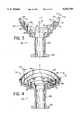
- FIG. 1is a perspective view of a contoured circular corrugated horn
- FIG. 2is a plan view of FIG. 1;
- FIG. 3is a cross-sectional view from 3--3 of FIG. 2;
- FIG. 4is a cross-sectional view from 4--4 of FIG. 2;
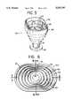
- FIG. 5is a perspective view of a non-circular corrugated horn
- FIG. 6is a plan view of FIG. 5;
- FIG. 7is a cross-sectional view from 7--7 of FIG. 6;
- FIG. 8is a cross-sectional view from 8--8 of FIG. 6;
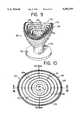
- FIG. 9is a perspective view of a non-circular contoured corrugated horn
- FIG. 10is a plan view of FIG. 9;
- FIG. 11is a cross-sectional view from 11--11 of FIG. 10.
- FIG. 12is a cross-sectional view from 12--12 of FIG. 10.
- the circular contoured corrugated (“CCC") horn 20is preferably constructed of zinc. However, any conductive material like aluminum, brass, copper or metalized plastic may be used.
- the CCC horncomprises a wave guide 22 having two ends which are referred to herein as upper and a lower ends. The upper end of the wave guide 22 opens into a horn 24.
- the wave guide 22 and the horn 24are radially disposed about a horn axis z.
- a plurality of ridges 28are disposed upon the inner surface of the horn 24, each ridge being oriented parallel to the horn axis z.
- the shape of the ridges 28is not critical to this invention and may be rounded, square or triangular, etc.
- a transition section 26is located towards the bottom end of the horn 24 and provides a transition from the wave guide 22 to the horn 24.
- Each of the ridges 28is located at specified stepped intervals along the inner surface of the horn 24 in the direction of arrow A, with the top surface 29 of the uppermost ridge 28 defining the top surface of the horn 24.
- Each of these "steps"has both a vertical dimension referred to herein as the step height 30, and a horizontal dimension referred to herein as the slot width 32.
- the horn 24is "flared" at an angle called the semi-flare angle ⁇ , defined as the angle between a line drawn parallel to the horn axis z, and a line passing through the top surfaces 29 of adjacent ridges 28. It is the semi-flare angle ⁇ that controls the beamwidth provided by the CCC horn 20, with wider beamwidths being provided by using larger semi-flare angles ⁇ .
- each ridge 28varies in height (dimension 31) around the circumference of the horn 24 in the direction of arrow B (FIG. 3).
- the step heights 30also vary around the circumference of the horn 24.
- the changing ridge heights 31 and step heights 30result in a uniformly undulating top surface 29, and a varying semi-flare angle ⁇ around the circumference of the horn 24 (Compare FIGS. 3 and 4).
- the changing semi-flare angle ⁇results in the beamwidth changing around the Z-axis, causing the CCC horn 20 to emit an elliptical or otherwise non-circular beam.
- the ridge heights 31 and step heights 30are changed within a specified range depending on the required semi-flare angle ⁇ to produce a beam of the desired shape.
- ellipticalis not limited to a shape meeting the mathematical criteria of a true ellipse, but rather, is used to include other non-circular, generally oval, shapes.
- the varying ridge heights 31 and/or step heights 30may be used to provide a beam with any non-circular shape. For example, a race track, a rounded rectangle, a rhombus with rounded corners, or an amoeboid shape with no symmetry are all included in the term "non-circular.”
- transition section 26is shown as a circle of uniform height 31 around the circumference of the horn 24, the transition section 26 may also be contoured and/or non-circular, where such contouring and/or shaping is required to produce a particular elliptical or other non-circular beam.
- An optional lip 34is attached to the outer surface of the horn 24. This provides a means for attaching a protective cover (not shown) over the CCC horn 20.
- An optional flange like base 36may be attached to the lower end of the wave guide 22 to provide securing means for the CCC horn 20.
- each ridge 28varied in height 31 between 0.498 inch (FIG. 3) and 0.395 inch (FIG. 4) around the circumference of horn 24 in the direction of arrow B.
- the step heights 30varied between 0.295 inch (FIG. 3) and 0.090 inch (FIG. 4) around the circumference of the horn 24.
- the semi-flare anglevaried between 40° (FIG. 3) and 70° (FIG. 7), and thereby provided the desired elliptical beam.
- these dimensionsare merely illustrative.
- step heights 30 and/or ridge heights 31vary sufficiently to change the semi-flare angle ⁇ so as to cause the CCC horn 20 to provide the desired non-circular beam.
- the ridge heights 31 and step heights 30are shown to vary in phase with successive ridges 28. However, this is not required by the present invention.
- the ridge heights 31 and/or step heights 30may vary independently of adjacent ridges 28 and still produce an undulating top surface 29 sufficient to provide the required non-circular beam.
- a further advantage of a CCC horn 20 constructed according to this inventionis that, because each ridge 28 is aligned parallel to the horn axis z, as opposed to perpendicular, or at some other angle with respect to the horn axis z, the CCC horn 20 may readily be die casted in accordance with known die casting methods. Also, the parallel aligned ridges 28 facilitates other manufacturing methods, for example, other casting methods or numerical machining techniques.
- FIGS. 5-8illustrate a non-circular corrugated ("NC") horn 40 which also provides an elliptical beam or non-circular beam for use with elliptical and other non-circular antennas.
- the NC horn 40comprises a wave guide 42 having a lower end and an upper end. The upper end of the wave guide 42 opens into a horn 44.
- the wave guide 42 and the horn 44are disposed about a horn axis z.
- a plurality of ridges 48are disposed upon the inner surface of the horn 44, with each ridge being oriented parallel to the horn axis z. This allows the NC horn 40 to be readily constructed via known die casting methods.
- a transition section 46is located at the bottom end of the horn 44, and provides a transition from the wave guide 42 to the horn 44.
- Each of the other ridges 48is located at specified stepped intervals along the inner surface of the horn 44 in the direction of arrow A, with the top surface 49 of the uppermost ridge 48 defining the top surface of the horn 44.
- Each of these "steps"has both a vertical dimension or step height 50, and a horizontal dimension or slot width 52.
- the ridge heights 51 and the step heights 50are constant around the surface of horn 44.
- the slot widths 52 and/or the ridge widths 53may be changed within a specified range around the circumference of the horn 44 in the direction of arrow B. The range within which the slot widths 52 and/or the ridge width 53 may vary depends on the desired shape of the NC horn 40, and ultimately on the desired elliptical or otherwise non-circular beam to be emitted.
- the horn 44is non-circular as viewed from the front of the NC horn 40 looking down the z axis towards the wave guide 42.
- the changing slot widths 52 and/or ridge widths 53cause the semi-flare angle ⁇ to change around the circumference of the horn 44 in the direction of arrow B. It is the changing semi-flare angle ⁇ that provides an elliptical beam or a non-circular beam, as desired.
- transition section 46is shown as a ridge of uniform height 51 around the circumference of the horn 44, the transition section 46 may also be contoured where such contouring is required to produce a particular elliptical or other non-circular beam.
- An optional flange like base 56may be attached to the lower end of the wave guide 42 to provide securing means for the NC horn 20.
- the ridge width 53was constant at 0.060 inch, while the adjacent slot widths 52 varied in phase with each other between 0.305 inch (FIG. 7) and 0.132 inch (FIG. 8). This gave the horn 44 its non-circular shape (FIG. 6). Although the ridge heights 51 and step heights 50 remained constant, the changing slot widths 52 caused the semi-flare angle ⁇ to change between 44.1° (FIG. 7) and 27° (FIG. 8) around the circumference of the horn 44, causing the NC horn 40 to emit the desired non-circular beam. It is again emphasized that all dimensions given are strictly for illustrative purposes.
- the slot widths 52must only vary within a range sufficient to change the semi-flare angle ⁇ the amount required to provide the required elliptical beam. Further, there is no requirement that successive ridges 48 vary in phase with each other. It is entirely within the scope of this invention for the slot widths 52 and/or the ridge widths 53 to vary independent of the ridge widths of adjacent ridges 48 and the corresponding adjacent slot widths 52.
- transition section 46 and the ridges 48are all oriented parallel to the horn axis z. This parallel orientation provides a NC horn 40 that is readily constructed through known die casting techniques.
- a non-circular contoured corrugated (“NCC") horn 60comprises a wave guide 62 having a lower end and an upper end. The upper end of the wave guide 62 opens into a horn 64.
- the wave guide 62 and the horn 64are radially disposed about a horn axis z.
- a plurality of ridges 68are disposed upon the inner surface of the horn 64, each ridge being oriented parallel to the horn axis z.
- a transition section 66is located at the bottom of the horn 64 and provides a transition from the wave guide 62 to the horn 64.
- Each of the ridges 68is located at specified stepped intervals along the inner surface of the horn 64 in the direction of arrow A, with the top surface 69 of the uppermost ridge 68 defining the top surface of the horn 64.
- Each of these "steps”has both a vertical dimension or step height 70, and a horizontal dimension or slot width 72.
- the horn 64is "flared" at the semi-flare angle ⁇ , defined as the angle between a line drawn parallel to the horn axis z, and a line passing through the top surfaces 69 of adjacent ridges 78.
- the nature of the beam emittedis a function of the semi-flare angle ⁇ , and thus, by varying the semi-flare angle the desired elliptical beam may be emitted by the NCC horn 60.
- a desired elliptical beammay be provided by changing one or more of: (a) the ridge heights 71 of each ridge 68 around the circumference of the horn 64; (b) the step heights 70 between successive ridges 68; (c) the slot width 72 between successive ridges 68; and/or the ridge width 73 of successive ridges 68.
- adjacent ridges 68are changed in phase with each other resulting in a horn 64 that is both undulating and non-circular.
- the ridge heights 71 and step heights 70vary within a range sufficient to provide the desired contoured or undulating shape of the horn 64.
- the slot widths 72also vary within a range sufficient to provide the desired non-circular shape of the horn 64.
- This desired shapedetermines the manner in which the semi-flare angle ⁇ will change around the circumference of the horn 64 in the direction of arrow B, and will thus determine the nature of the beam emitted.
- the desired beamcould be any non-circular beam to include an elliptically shaped beam, a race track shaped beam, a rectangular or rhomboidal shaped beam with rounded edges, or a completely non-symmetrically shaped beam.
- transition section 66is shown as a ridge of uniform height around the circumference of the horn 64, the transition section 66 may also be contoured in phase with the ridges 68 where it is required to produce a particular non-circular beam.
- An optional lip 74may be attached to the outer surface of the horn 64. This provides a means for attaching a protective cover (not shown) over the NCC horn 60.
- An optional flange like base 76may be attached to the lower end of the wave guide 62 to provide securing means for the NCC horn 60.
- the ridge heights 71varied between 0.496 inch (FIG. 11) and 0.373 inch (FIG. 12); the step heights 70 varied between 0.333 inch (FIG. 11) and 0.086 inch (FIG. 12); and the slot widths 72 varied between 0.156 inch and 0.259 inch around the circumference of the horn 64 in the direction of arrow B.
- the ridge widths 73were not varied.
- the semi-flare angle ⁇varied between 33° (FIG. 11) and 75° (FIG. 12).
- the NCC horn 60has the further advantage of being readily constructed by known die casting methods or other numerical machining methods because the ridges 68 are oriented parallel to the horn axis z.
Landscapes
- Waveguide Aerials (AREA)
- Lasers (AREA)
Abstract
Description
Claims (22)
Priority Applications (9)
| Application Number | Priority Date | Filing Date | Title |
|---|---|---|---|
| US08/348,790US5552797A (en) | 1994-12-02 | 1994-12-02 | Die-castable corrugated horns providing elliptical beams |
| AT01107630TATE365987T1 (en) | 1994-12-02 | 1995-11-17 | CORRUPTED HORN RADIATOR PRODUCED USING A DIE-CASTING METHOD TO PRODUCE ELLIPTICAL BEAMS OF RAYS |
| AT95942566TATE225086T1 (en) | 1994-12-02 | 1995-11-17 | CORRUPTED HORN LAMP, MANUFACTURED BY DIE CASTING PROCESS, FOR AWAKENING ELLIPTICAL BEAMS OF RAYS |
| PCT/US1995/015857WO1996017402A1 (en) | 1994-12-02 | 1995-11-17 | Die-castable corrugated horns providing elliptical beams |
| AU43750/96AAU4375096A (en) | 1994-12-02 | 1995-11-17 | Die-castable corrugated horns providing elliptical beams |
| EP01107630AEP1130679B1 (en) | 1994-12-02 | 1995-11-17 | Die-castable corrugated horns providing elliptical beams |
| DE69535525TDE69535525T2 (en) | 1994-12-02 | 1995-11-17 | A corrugated horn radiator produced by means of a pressure casting process for producing elliptical radiation bundles |
| DE69528392TDE69528392T2 (en) | 1994-12-02 | 1995-11-17 | WAVED HORN RADIATOR, MANUFACTURED BY MEANS OF DIE CASTING, FOR THE WAKING UP OF ELLIPTICAL RADIO BUNCHES |
| EP95942566AEP0878030B1 (en) | 1994-12-02 | 1995-11-17 | Die-castable corrugated horns providing elliptical beams |
Applications Claiming Priority (1)
| Application Number | Priority Date | Filing Date | Title |
|---|---|---|---|
| US08/348,790US5552797A (en) | 1994-12-02 | 1994-12-02 | Die-castable corrugated horns providing elliptical beams |
Publications (1)
| Publication Number | Publication Date |
|---|---|
| US5552797Atrue US5552797A (en) | 1996-09-03 |
Family
ID=23369547
Family Applications (1)
| Application Number | Title | Priority Date | Filing Date |
|---|---|---|---|
| US08/348,790Expired - LifetimeUS5552797A (en) | 1994-12-02 | 1994-12-02 | Die-castable corrugated horns providing elliptical beams |
Country Status (6)
| Country | Link |
|---|---|
| US (1) | US5552797A (en) |
| EP (2) | EP0878030B1 (en) |
| AT (2) | ATE365987T1 (en) |
| AU (1) | AU4375096A (en) |
| DE (2) | DE69535525T2 (en) |
| WO (1) | WO1996017402A1 (en) |
Cited By (25)
| Publication number | Priority date | Publication date | Assignee | Title |
|---|---|---|---|---|
| US5657033A (en)* | 1995-06-07 | 1997-08-12 | Hughes Electronics | Cofired ceramic notch and horn antennas |
| USD431555S (en)* | 1999-10-22 | 2000-10-03 | Channel Master Llc | Housing for antenna feed horn and transmit electronics |
| EP1018781A3 (en)* | 1999-01-06 | 2001-03-07 | Alps Electric Co., Ltd. | Feed horn having elliptic open end |
| US6208309B1 (en)* | 1999-03-16 | 2001-03-27 | Trw Inc. | Dual depth aperture chokes for dual frequency horn equalizing E and H-plane patterns |
| US6356241B1 (en)* | 1998-10-20 | 2002-03-12 | Raytheon Company | Coaxial cavity antenna |
| WO2002050947A1 (en)* | 2000-12-19 | 2002-06-27 | Radiant Networks Plc | Communication apparatus, method of transmission and antenna apparatus |
| US6549173B1 (en)* | 1998-06-02 | 2003-04-15 | Channel Master Limited | Antenna feed and a reflector antenna system and a low noise (lnb) receiver, both with such an antenna feed |
| US6580400B2 (en)* | 2000-03-31 | 2003-06-17 | Alps Electric Co., Ltd. | Primary radiator having improved receiving efficiency by reducing side lobes |
| US6618021B1 (en)* | 2002-06-12 | 2003-09-09 | The Boeing Company | Electrically small aperture antennae with field minimization |
| US20040021614A1 (en)* | 2002-02-20 | 2004-02-05 | Prodelin Corporation | Circularly polarized receive/transmit elliptic feed horn assembly for satellite communications |
| US6720932B1 (en)* | 1999-01-08 | 2004-04-13 | Channel Master Limited | Multi-frequency antenna feed |
| US6879298B1 (en)* | 2003-10-15 | 2005-04-12 | Harris Corporation | Multi-band horn antenna using corrugations having frequency selective surfaces |
| US20050116871A1 (en)* | 2003-09-25 | 2005-06-02 | Prodelin Corporation | Feed assembly for multi-beam antenna with non-circular reflector, and such an assembly that is field-switchable between linear and circular polarization modes |
| US20050237253A1 (en)* | 2004-04-22 | 2005-10-27 | Kuo Steven S | Feed structure and antenna structures incorporating such feed structures |
| US20060082513A1 (en)* | 2004-10-15 | 2006-04-20 | Harris Corporation | Simultaneous multi-band ring focus reflector antenna-broadband feed |
| US20070285329A1 (en)* | 2006-06-09 | 2007-12-13 | Andrew Corporation | Squint-Beam Corrugated Horn |
| US20080297428A1 (en)* | 2006-02-24 | 2008-12-04 | Northrop Grumman Corporation | High-power dual-frequency coaxial feedhorn antenna |
| USD598905S1 (en)* | 2005-05-18 | 2009-08-25 | Cook Scott J | Antenna feed horn |
| US20100060536A1 (en)* | 2008-09-10 | 2010-03-11 | Chang-Hsiu Huang | Multiband satellite antenna |
| US20150097747A1 (en)* | 2013-10-04 | 2015-04-09 | Ki Min HWANG | Antenna system for simultaneous triple-band satellite communication |
| US20160072190A1 (en)* | 2014-09-05 | 2016-03-10 | Lisa Draexlmaier Gmbh | Ridged horn antenna having additional corrugation |
| JP2018170548A (en)* | 2017-03-29 | 2018-11-01 | 日本無線株式会社 | Antenna feeding section |
| CN109273856A (en)* | 2017-07-18 | 2019-01-25 | 中国航空工业集团公司济南特种结构研究所 | A kind of low standing-wave ratio antenna structure |
| US10236586B2 (en)* | 2017-01-03 | 2019-03-19 | Winegard Company | Corrugated feed horn for producing an oval beam |
| US10892549B1 (en) | 2020-02-28 | 2021-01-12 | Northrop Grumman Systems Corporation | Phased-array antenna system |
Families Citing this family (2)
| Publication number | Priority date | Publication date | Assignee | Title |
|---|---|---|---|---|
| KR20030047233A (en)* | 2001-12-08 | 2003-06-18 | 삼성전기주식회사 | Feed horn for improving gain and directivity of satellite antenna |
| JP5854888B2 (en)* | 2011-08-29 | 2016-02-09 | 三菱電機株式会社 | Primary radiator and antenna device |
Citations (19)
| Publication number | Priority date | Publication date | Assignee | Title |
|---|---|---|---|---|
| FR1008954A (en)* | 1950-01-20 | 1952-05-23 | Csf | Air cone improvements for ultrashort waves |
| US3618106A (en)* | 1968-11-15 | 1971-11-02 | Plessey Co Ltd | Antenna feed systems |
| US3732571A (en)* | 1970-11-24 | 1973-05-08 | Marconi Co Ltd | Microwave horn aerial with spiral corrugated inner surface |
| US3924237A (en)* | 1974-07-24 | 1975-12-02 | Nasa | Horn antenna having v-shaped corrugated slots |
| US3936837A (en)* | 1975-02-25 | 1976-02-03 | The United States Of America As Represented By The Secretary Of The Navy | Corrugated horn fed offset paraboloidal reflector |
| US4048592A (en)* | 1975-02-28 | 1977-09-13 | Thomson-Csf | Arrangement for extracting divergence-measuring modes from a corrugated guide and tracking antenna incorporating same |
| US4194380A (en)* | 1977-06-29 | 1980-03-25 | Andrew Corporation | Corrugated elliptical waveguide with permanent twist |
| DE3144319A1 (en)* | 1981-11-07 | 1983-05-19 | Deutsche Bundespost, vertreten durch den Präsidenten des Fernmeldetechnischen Zentralamtes, 6100 Darmstadt | "HORN RADIATOR" |
| DE3146273A1 (en)* | 1981-11-21 | 1983-05-26 | Licentia Patent-Verwaltungs-Gmbh, 6000 Frankfurt | Grooved horn aerial |
| US4472721A (en)* | 1981-03-13 | 1984-09-18 | Licentia Patent-Verwaltungs-G.M.B.H. | Broadband corrugated horn radiator |
| US4636798A (en)* | 1984-05-29 | 1987-01-13 | Seavey Engineering Associates, Inc. | Microwave lens for beam broadening with antenna feeds |
| US4658258A (en)* | 1983-11-21 | 1987-04-14 | Rca Corporation | Taperd horn antenna with annular choke channel |
| WO1988001444A1 (en)* | 1986-08-13 | 1988-02-25 | Integrated Visual, Inc. | Flat phased array antenna |
| WO1989009500A1 (en)* | 1988-03-31 | 1989-10-05 | Colebrand Limited | Reflector for electromagnetic radiation |
| US4902988A (en)* | 1989-01-27 | 1990-02-20 | Chapparal Communications, Inc. | Control for flexible probe |
| GB2224603A (en)* | 1988-08-30 | 1990-05-09 | British Satellite Broadcasting | Flat plate array antenna |
| WO1991020109A1 (en)* | 1990-06-14 | 1991-12-26 | Collins John Louis Frederick C | Microwave antennas |
| US5086304A (en)* | 1986-08-13 | 1992-02-04 | Integrated Visual, Inc. | Flat phased array antenna |
| US5486839A (en)* | 1994-07-29 | 1996-01-23 | Winegard Company | Conical corrugated microwave feed horn |
Family Cites Families (2)
| Publication number | Priority date | Publication date | Assignee | Title |
|---|---|---|---|---|
| DE3009254C2 (en)* | 1980-03-11 | 1982-07-08 | Licentia Patent-Verwaltungs-Gmbh, 6000 Frankfurt | Antenna exciter with a radiation pattern of elliptical cross-section |
| FR2607968B1 (en)* | 1986-12-09 | 1989-02-03 | Alcatel Thomson Faisceaux | SOURCE OF ILLUMINATION FOR TELECOMMUNICATIONS ANTENNA |
- 1994
- 1994-12-02USUS08/348,790patent/US5552797A/ennot_activeExpired - Lifetime
- 1995
- 1995-11-17DEDE69535525Tpatent/DE69535525T2/ennot_activeExpired - Fee Related
- 1995-11-17AUAU43750/96Apatent/AU4375096A/ennot_activeAbandoned
- 1995-11-17EPEP95942566Apatent/EP0878030B1/ennot_activeExpired - Lifetime
- 1995-11-17ATAT01107630Tpatent/ATE365987T1/ennot_activeIP Right Cessation
- 1995-11-17EPEP01107630Apatent/EP1130679B1/ennot_activeExpired - Lifetime
- 1995-11-17WOPCT/US1995/015857patent/WO1996017402A1/enactiveIP Right Grant
- 1995-11-17DEDE69528392Tpatent/DE69528392T2/ennot_activeExpired - Fee Related
- 1995-11-17ATAT95942566Tpatent/ATE225086T1/ennot_activeIP Right Cessation
Patent Citations (20)
| Publication number | Priority date | Publication date | Assignee | Title |
|---|---|---|---|---|
| FR1008954A (en)* | 1950-01-20 | 1952-05-23 | Csf | Air cone improvements for ultrashort waves |
| US3618106A (en)* | 1968-11-15 | 1971-11-02 | Plessey Co Ltd | Antenna feed systems |
| US3732571A (en)* | 1970-11-24 | 1973-05-08 | Marconi Co Ltd | Microwave horn aerial with spiral corrugated inner surface |
| US3924237A (en)* | 1974-07-24 | 1975-12-02 | Nasa | Horn antenna having v-shaped corrugated slots |
| US3936837A (en)* | 1975-02-25 | 1976-02-03 | The United States Of America As Represented By The Secretary Of The Navy | Corrugated horn fed offset paraboloidal reflector |
| US4048592A (en)* | 1975-02-28 | 1977-09-13 | Thomson-Csf | Arrangement for extracting divergence-measuring modes from a corrugated guide and tracking antenna incorporating same |
| US4194380A (en)* | 1977-06-29 | 1980-03-25 | Andrew Corporation | Corrugated elliptical waveguide with permanent twist |
| US4472721A (en)* | 1981-03-13 | 1984-09-18 | Licentia Patent-Verwaltungs-G.M.B.H. | Broadband corrugated horn radiator |
| DE3144319A1 (en)* | 1981-11-07 | 1983-05-19 | Deutsche Bundespost, vertreten durch den Präsidenten des Fernmeldetechnischen Zentralamtes, 6100 Darmstadt | "HORN RADIATOR" |
| DE3146273A1 (en)* | 1981-11-21 | 1983-05-26 | Licentia Patent-Verwaltungs-Gmbh, 6000 Frankfurt | Grooved horn aerial |
| US4658258A (en)* | 1983-11-21 | 1987-04-14 | Rca Corporation | Taperd horn antenna with annular choke channel |
| US4636798A (en)* | 1984-05-29 | 1987-01-13 | Seavey Engineering Associates, Inc. | Microwave lens for beam broadening with antenna feeds |
| WO1988001444A1 (en)* | 1986-08-13 | 1988-02-25 | Integrated Visual, Inc. | Flat phased array antenna |
| US4959658A (en)* | 1986-08-13 | 1990-09-25 | Collins John L | Flat phased array antenna |
| US5086304A (en)* | 1986-08-13 | 1992-02-04 | Integrated Visual, Inc. | Flat phased array antenna |
| WO1989009500A1 (en)* | 1988-03-31 | 1989-10-05 | Colebrand Limited | Reflector for electromagnetic radiation |
| GB2224603A (en)* | 1988-08-30 | 1990-05-09 | British Satellite Broadcasting | Flat plate array antenna |
| US4902988A (en)* | 1989-01-27 | 1990-02-20 | Chapparal Communications, Inc. | Control for flexible probe |
| WO1991020109A1 (en)* | 1990-06-14 | 1991-12-26 | Collins John Louis Frederick C | Microwave antennas |
| US5486839A (en)* | 1994-07-29 | 1996-01-23 | Winegard Company | Conical corrugated microwave feed horn |
Non-Patent Citations (4)
| Title |
|---|
| R. E. Lawrie et al., IEE Transactions on Antennas And Propagation, Sep. 1966 (605 610).* |
| R. E. Lawrie et al., IEE Transactions on Antennas And Propagation, Sep. 1966 (605-610). |
| W. F. Bahret et al., IEE Transactions on Antennas And Propagation, Jul. 1968, (494 495).* |
| W. F. Bahret et al., IEE Transactions on Antennas And Propagation, Jul. 1968, (494-495). |
Cited By (42)
| Publication number | Priority date | Publication date | Assignee | Title |
|---|---|---|---|---|
| US5657033A (en)* | 1995-06-07 | 1997-08-12 | Hughes Electronics | Cofired ceramic notch and horn antennas |
| US6549173B1 (en)* | 1998-06-02 | 2003-04-15 | Channel Master Limited | Antenna feed and a reflector antenna system and a low noise (lnb) receiver, both with such an antenna feed |
| US20030132888A1 (en)* | 1998-06-02 | 2003-07-17 | Channel Master Limited | Antenna feed and a reflector antenna system and a low noise block (LNB) receiver, both with such an antenna feed |
| US6831612B2 (en)* | 1998-06-02 | 2004-12-14 | Channel Master Limited | Antenna feed and a reflector antenna system and a low noise block (LNB) receiver, both with such an antenna feed |
| US6356241B1 (en)* | 1998-10-20 | 2002-03-12 | Raytheon Company | Coaxial cavity antenna |
| EP1018781A3 (en)* | 1999-01-06 | 2001-03-07 | Alps Electric Co., Ltd. | Feed horn having elliptic open end |
| US6320554B1 (en) | 1999-01-06 | 2001-11-20 | Alps Electric Co., Ltd. | Feed horn having elliptic open end |
| US6720932B1 (en)* | 1999-01-08 | 2004-04-13 | Channel Master Limited | Multi-frequency antenna feed |
| US6208309B1 (en)* | 1999-03-16 | 2001-03-27 | Trw Inc. | Dual depth aperture chokes for dual frequency horn equalizing E and H-plane patterns |
| USD431555S (en)* | 1999-10-22 | 2000-10-03 | Channel Master Llc | Housing for antenna feed horn and transmit electronics |
| US6580400B2 (en)* | 2000-03-31 | 2003-06-17 | Alps Electric Co., Ltd. | Primary radiator having improved receiving efficiency by reducing side lobes |
| WO2002050947A1 (en)* | 2000-12-19 | 2002-06-27 | Radiant Networks Plc | Communication apparatus, method of transmission and antenna apparatus |
| US20040077320A1 (en)* | 2000-12-19 | 2004-04-22 | Timothy Jackson | Communication apparatus, method of transmission and antenna apparatus |
| US7327323B2 (en) | 2000-12-19 | 2008-02-05 | Intel Corporation | Communication apparatus, method of transmission and antenna apparatus |
| CN100375332C (en)* | 2000-12-19 | 2008-03-12 | 英特尔公司 | Communication apparatus, transmission method, and antenna apparatus |
| US20040021614A1 (en)* | 2002-02-20 | 2004-02-05 | Prodelin Corporation | Circularly polarized receive/transmit elliptic feed horn assembly for satellite communications |
| US7002528B2 (en) | 2002-02-20 | 2006-02-21 | Prodelin Corporation | Circularly polarized receive/transmit elliptic feed horn assembly for satellite communications |
| US6618021B1 (en)* | 2002-06-12 | 2003-09-09 | The Boeing Company | Electrically small aperture antennae with field minimization |
| US20050116871A1 (en)* | 2003-09-25 | 2005-06-02 | Prodelin Corporation | Feed assembly for multi-beam antenna with non-circular reflector, and such an assembly that is field-switchable between linear and circular polarization modes |
| US7236681B2 (en) | 2003-09-25 | 2007-06-26 | Prodelin Corporation | Feed assembly for multi-beam antenna with non-circular reflector, and such an assembly that is field-switchable between linear and circular polarization modes |
| US6879298B1 (en)* | 2003-10-15 | 2005-04-12 | Harris Corporation | Multi-band horn antenna using corrugations having frequency selective surfaces |
| US20050083241A1 (en)* | 2003-10-15 | 2005-04-21 | Zarro Michael S. | Multi-band horn antenna using corrugations having frequency selective surfaces |
| US20050237253A1 (en)* | 2004-04-22 | 2005-10-27 | Kuo Steven S | Feed structure and antenna structures incorporating such feed structures |
| US7034774B2 (en)* | 2004-04-22 | 2006-04-25 | Northrop Grumman Corporation | Feed structure and antenna structures incorporating such feed structures |
| US20060082513A1 (en)* | 2004-10-15 | 2006-04-20 | Harris Corporation | Simultaneous multi-band ring focus reflector antenna-broadband feed |
| US7187340B2 (en)* | 2004-10-15 | 2007-03-06 | Harris Corporation | Simultaneous multi-band ring focus reflector antenna-broadband feed |
| USD598905S1 (en)* | 2005-05-18 | 2009-08-25 | Cook Scott J | Antenna feed horn |
| US20080297428A1 (en)* | 2006-02-24 | 2008-12-04 | Northrop Grumman Corporation | High-power dual-frequency coaxial feedhorn antenna |
| US7511678B2 (en)* | 2006-02-24 | 2009-03-31 | Northrop Grumman Corporation | High-power dual-frequency coaxial feedhorn antenna |
| US20070285329A1 (en)* | 2006-06-09 | 2007-12-13 | Andrew Corporation | Squint-Beam Corrugated Horn |
| US7602347B2 (en)* | 2006-06-09 | 2009-10-13 | Raven Manufacturing Ltd. | Squint-beam corrugated horn |
| US20100060536A1 (en)* | 2008-09-10 | 2010-03-11 | Chang-Hsiu Huang | Multiband satellite antenna |
| US8054234B2 (en)* | 2008-09-10 | 2011-11-08 | Wistron Neweb Corp. | Multiband satellite antenna |
| US20150097747A1 (en)* | 2013-10-04 | 2015-04-09 | Ki Min HWANG | Antenna system for simultaneous triple-band satellite communication |
| US9768508B2 (en)* | 2013-10-04 | 2017-09-19 | Agency For Defense Development | Antenna system for simultaneous triple-band satellite communication |
| US20160072190A1 (en)* | 2014-09-05 | 2016-03-10 | Lisa Draexlmaier Gmbh | Ridged horn antenna having additional corrugation |
| US9859618B2 (en)* | 2014-09-05 | 2018-01-02 | Lisa Draeximaier GmbH | Ridged horn antenna having additional corrugation |
| US10236586B2 (en)* | 2017-01-03 | 2019-03-19 | Winegard Company | Corrugated feed horn for producing an oval beam |
| JP2018170548A (en)* | 2017-03-29 | 2018-11-01 | 日本無線株式会社 | Antenna feeding section |
| CN109273856A (en)* | 2017-07-18 | 2019-01-25 | 中国航空工业集团公司济南特种结构研究所 | A kind of low standing-wave ratio antenna structure |
| US10892549B1 (en) | 2020-02-28 | 2021-01-12 | Northrop Grumman Systems Corporation | Phased-array antenna system |
| US11251524B1 (en) | 2020-02-28 | 2022-02-15 | Northrop Grumman Systems Corporation | Phased-array antenna system |
Also Published As
| Publication number | Publication date |
|---|---|
| DE69528392D1 (en) | 2002-10-31 |
| DE69528392T2 (en) | 2003-06-12 |
| ATE225086T1 (en) | 2002-10-15 |
| AU4375096A (en) | 1996-06-19 |
| EP0878030A1 (en) | 1998-11-18 |
| ATE365987T1 (en) | 2007-07-15 |
| EP1130679A3 (en) | 2002-06-26 |
| EP0878030A4 (en) | 1999-04-07 |
| EP1130679A2 (en) | 2001-09-05 |
| EP1130679B1 (en) | 2007-06-27 |
| EP0878030B1 (en) | 2002-09-25 |
| DE69535525D1 (en) | 2007-08-09 |
| WO1996017402A1 (en) | 1996-06-06 |
| DE69535525T2 (en) | 2008-04-17 |
Similar Documents
| Publication | Publication Date | Title |
|---|---|---|
| US5552797A (en) | Die-castable corrugated horns providing elliptical beams | |
| US5446792A (en) | Reflection-type speaker apparatus | |
| US5121129A (en) | EHF omnidirectional antenna | |
| CA1219364A (en) | Tapered horn antenna with choke channel | |
| EP0140465A2 (en) | Defined-coverage loudspeaker horn | |
| JPH01316008A (en) | Vertical antenna | |
| KR101292230B1 (en) | Compact nonaxisymmetric double-reflector antenna | |
| US4947181A (en) | Asymmetrical biconical horn antenna | |
| US5883604A (en) | Horn antenna | |
| JPS6135721B2 (en) | ||
| KR20010034238A (en) | Multi-primary radiator, down converter and multi-beam antenna | |
| US4439748A (en) | Corrugated waveguide or feedhorn assembled from grooved pieces | |
| US4439774A (en) | Antenna reflector with triangulated cellular back structure | |
| CN220873856U (en) | Antenna device and system | |
| US4607260A (en) | Asymmetrically configured horn antenna | |
| US3821745A (en) | Transmitting antenna employing parasitic end fire directors | |
| JPH04120903A (en) | Plane antenna | |
| US6137448A (en) | Center FED traveling wave antenna capable of high beam tilt and null free stable elevation pattern | |
| CN116598783A (en) | Air waveguide array antenna with sawtooth structure | |
| JPS57157603A (en) | Reflector antenna | |
| EP0421757A2 (en) | Microwave antenna | |
| JPS5895407A (en) | Conical beam array antenna | |
| JPH03155203A (en) | Primary radiator for parabolic antenna | |
| JP2556130B2 (en) | Corrugated horn | |
| CN113871858B (en) | Ridge waveguide antenna subarray with expandable array and array |
Legal Events
| Date | Code | Title | Description |
|---|---|---|---|
| AS | Assignment | Owner name:AVNET, INC., NEW YORK Free format text:ASSIGNMENT OF ASSIGNORS INTEREST;ASSIGNOR:COOK, SCOTT J.;REEL/FRAME:007342/0010 Effective date:19950208 | |
| STCF | Information on status: patent grant | Free format text:PATENTED CASE | |
| AS | Assignment | Owner name:CHANNEL MASTER, INC., NORTH CAROLINA Free format text:ASSIGNMENT OF ASSIGNORS INTEREST;ASSIGNOR:AVNET, INC.;REEL/FRAME:008800/0276 Effective date:19971030 | |
| AS | Assignment | Owner name:COMERICA BANK, MICHIGAN Free format text:SECURITY AGREEMENT;ASSIGNOR:CHANNEL MASTER, INC.;REEL/FRAME:008907/0675 Effective date:19971010 | |
| AS | Assignment | Owner name:CHANNEL MASTER L.L.C., NORTH CAROLINA Free format text:ASSIGNMENT OF ASSIGNORS INTEREST;ASSIGNOR:CHANNEL MASTER, INC.;REEL/FRAME:009350/0599 Effective date:19980729 | |
| FPAY | Fee payment | Year of fee payment:4 | |
| AS | Assignment | Owner name:COMERICA BANK, AS AGENT, MICHIGAN Free format text:SECURITY AGREEMENT;ASSIGNOR:CHANNEL MASTER LLC A/K/A CHANNEL MASTER L.L.C.;REEL/FRAME:013740/0126 Effective date:20021202 | |
| FPAY | Fee payment | Year of fee payment:8 | |
| AS | Assignment | Owner name:ANDREW CORPORATION, ILLINOIS Free format text:ASSIGNMENT OF ASSIGNORS INTEREST;ASSIGNOR:CHANNEL MASTER LLC;REEL/FRAME:019628/0231 Effective date:20031121 | |
| AS | Assignment | Owner name:CHANNEL MASTER LLC, NORTH CAROLINA Free format text:RELEASE BY SECURED PARTY;ASSIGNOR:COMERICA BANK, AS AGENT;REEL/FRAME:019920/0358 Effective date:20031001 | |
| FPAY | Fee payment | Year of fee payment:12 | |
| AS | Assignment | Owner name:ASC SIGNAL CORPORATION, NORTH CAROLINA Free format text:ASSIGNMENT OF ASSIGNORS INTEREST;ASSIGNOR:ANDREW CORPORATION;REEL/FRAME:020886/0407 Effective date:20080131 | |
| AS | Assignment | Owner name:PNC BANK, NATIONAL ASSOCIATION, PENNSYLVANIA Free format text:SECURITY AGREEMENT;ASSIGNOR:ASC SIGNAL CORPORATION;REEL/FRAME:021018/0816 Effective date:20080422 | |
| AS | Assignment | Owner name:ASC SIGNAL CORPORATION, NORTH CAROLINA Free format text:RELEASE BY SECURED PARTY;ASSIGNOR:PNC BANK, NATIONAL ASSOCIATION;REEL/FRAME:030320/0276 Effective date:20090529 Owner name:RAVEN NC, LLC, NORTH CAROLINA Free format text:ASSIGNMENT OF ASSIGNORS INTEREST;ASSIGNOR:ASC SIGNAL CORPORATION;REEL/FRAME:030320/0460 Effective date:20090529 Owner name:RAVEN ANTENNA SYSTEMS INC., NORTH CAROLINA Free format text:CHANGE OF NAME;ASSIGNOR:RAVEN NC, LLC;REEL/FRAME:030320/0685 Effective date:20100305 | |
| AS | Assignment | Owner name:PNC BANK, NATIONAL ASSOCIATION, PENNSYLVANIA Free format text:SECURITY AGREEMENT;ASSIGNOR:RAVEN ANTENNA SYSTEMS, INC.;REEL/FRAME:031891/0183 Effective date:20131223 | |
| AS | Assignment | Owner name:RAVEN ANTENNA SYSTEMS INC., NORTH CAROLINA Free format text:RELEASE BY SECURED PARTY;ASSIGNOR:PNC BANK, NATIONAL ASSOCIATION;REEL/FRAME:059919/0577 Effective date:20170501 |