US5552735A - Multi-gigahertz single flux quantum switch - Google Patents
Multi-gigahertz single flux quantum switchDownload PDFInfo
- Publication number
- US5552735A US5552735AUS08/319,707US31970794AUS5552735AUS 5552735 AUS5552735 AUS 5552735AUS 31970794 AUS31970794 AUS 31970794AUS 5552735 AUS5552735 AUS 5552735A
- Authority
- US
- United States
- Prior art keywords
- channels
- line
- switch
- pair
- input
- Prior art date
- Legal status (The legal status is an assumption and is not a legal conclusion. Google has not performed a legal analysis and makes no representation as to the accuracy of the status listed.)
- Expired - Fee Related
Links
Images


Classifications
- H—ELECTRICITY
- H03—ELECTRONIC CIRCUITRY
- H03K—PULSE TECHNIQUE
- H03K17/00—Electronic switching or gating, i.e. not by contact-making and –breaking
- H03K17/51—Electronic switching or gating, i.e. not by contact-making and –breaking characterised by the components used
- H03K17/92—Electronic switching or gating, i.e. not by contact-making and –breaking characterised by the components used by the use, as active elements, of superconductive devices
Definitions
- This inventionrelates to the field of high speed communication, and, more particularly, to the field of superconductive digital switches for use in multi-gigahertz applications.
- Fiber optic technologyoffers gigahertz speed data transmission to make a future multi-gigahertz data communication feasible.
- SONETsynchronous optical network
- ATMasynchronous transfer mode
- Superconductivitycan provide a solution to the problem of multi-gigahertz digital switching by using single flux quantum (SFQ) Josephson circuits.
- SFQsingle flux quantum
- An SFQ Josephson circuitcan be operated at orders of magnitude higher speeds than that of the competing semiconductor technologies. Also, the power required to operate SFQ circuits is orders of magnitude lower than that required for other technologies.
- SFQ circuitsutilize non-hysteretic Josephson junctions which can be switched from a "0" state to a "1" state which self-resets to the "0" state.
- the existence and non-existence of a voltage pulserepresents the state and "0" state, respectively.
- Typical values of I c R nare a few tenths of a mV to a few mV, resulting in the values of ⁇ o only a few picoseconds or less.
- An SFQ counter and an SFQ shift registerwere demonstrated to operate properly at speeds above 100 Gbps with power consumption of only tens of ⁇ W.
- the preferred switch implementationincludes a pair of input channels and a pair of output channels.
- the switchreceives an input signal from each of the pair of input channels and transmits an output signal to each of the pair of output channels.
- Four line channels provided within the switchconnect each input channel and each output channel.
- a line channel switchis provided in each line channel.
- Each line channel switchis operable by a control signal to open or close each of the four line channels.
- Josephson junctionsare used in the line channel switches to control the closing of the line channel switch.
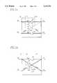
- FIG. 1ais a schematic drawing showing the basic operation of a presently preferred-embodiment of the switch of the present invention showing the "bar" action.
- FIG. 1bis a schematic drawing showing the basic operation of a presently preferred embodiment of the switch of the present invention showing the "cross" action.
- FIG. 2is a circuit diagram of a presently preferred embodiment of the line switch used in the present invention.
- FIG. 3is a circuit diagram of the switch of FIG. 1.
- FIG. 4is a chart presenting the results of a simulation test performed on a switch modeled upon the switch of FIG. 3.
- FIG. 5is a schematic representation of a "bar" signal operation and the results of test data therefor.
- FIG. 6is a schematic representation of a "cross" signal operation and the results of test data therefor.
- FIG. 1a and 1bare schematic diagrams illustrating the basic principle of the switch operation used to build an SFQ switch.
- the switch 10is controlled by two control signals 12 and 14 which open and close the line switches 16 for a "bar" action as shown in FIG. 1a and a "cross” action as shown in FIG. 1b.
- the control signals 12 and 14are applied for the "bar” action as shown in FIG. 1a, signals arriving at input channels 18 and 20 are sent to output channels 22 and 24, respectively.
- For the "cross” action, as shown in FIG. 1bsignals arriving at input channels 18 and 20 are sent crossed to output channels 24 and 22, respectively.
- FIG. 2shows a line switch 16 composed of two non-hysteretic Josephson junctions 26 and 28 and two inductors 30.
- the bias current I bias 32blocks the passage of SFQ voltage pulses through the line switch 16.
- the operation of the switch 16is as follows.
- the input signalis introduced into the input channel 34 in the form of the stream of SFQ voltage pulses.
- the input junction JJ input 36experiences a momentary voltage state corresponding to a single magnetic flux quantum and transfers the voltage pulse to the line switch 16.
- I bias0
- the line switch 16is closed and an input SFQ voltage pulse passes through the superconducting inductors 30, and the unbiased Josephson junctions, JJ buffer 26 and JJ block 28, reaching to the output junction JJ output 38.
- JJ output 38experiences a momentary voltage state and outputs an SFQ voltage pulse to output channel 40. In such a manner, the line switch 16 is "closed".
- JJ block 28becomes current biased and blocks the SFQ voltage pulses trying to pass through the circuit.
- An SFQ pulse introduced to the circuitputs a magnetic flux quantum into the closed loop consisting of two inductors and four junctions. This causes an additional current flow through JJ block 28 and causes this junction to switch to a momentary voltage state and drives the magnetic flux out of the loop. Since this action happens only on JJ block 28, JJ output 38 does not experience a momentary voltage state. There is no output SFQ voltage pulse. In such a manner, the line switch 16 is "opened".
- an SFQ voltage pulsecan be transferred to this output channel even when the first line switch 16 is open and causes JJ output 38 to experience a momentary voltage state.
- this output SFQ voltage pulse caused by a second input channelis prevented from flowing back to the first input channel by JJ buffer 26.
- JJ buffer 26prevents the voltage pulse flowing from the input channel 34 to the output channel 40.
- FIG. 3The complete circuit diagram of the SFQ switch 10 is shown in FIG. 3 where four line switches 42, 44, 46, and 48, similar to line switch 16 from FIG. 2, are used.
- the input signal in the form of an SFQ pulseis fed into input channel 18, it drives JJ input 50 into the voltage state momentarily, creating an SFQ voltage pulse which propagates to both of two line switches 42 and 44, one for the "bar” action and the other for the "cross” action.
- the input signal fed into input channel 20drives JJ input 52 into the voltage state creating an SFQ voltage pulse which propagates to both of two line switches 46 and 48.
- the switch 10is controlled by two control lines, BAR 54 and CROSS 56.
- BAR control line 54When BAR control line 54 is biased and CROSS control line 56 is unbiased, the two line switches 44 and 46 for the "bar" action are closed and those line switches 42 and 48 for the "cross” action open.
- the input signals on channels 18 and 20get through to output channels 22 and 24, respectively.
- BAR control line 54is unbiased and CROSS control line 56 is biased, these two input signals cross to output channels 24 and 22, respectively.
- FIG. 4shows the simulation result of the circuit operating at 10 Gbps.
- I bias400 ⁇ A.
- Digital signals "11010” and "10110”have been used for signal 1 and signal 2, respectively, to track the paths though which the signals followed.
- Signal 1was fed into input channel 1 and signal 2 was fed into input channel 2.
- FIG. 4clearly shows that the signals 1 and 2 move through the SFQ switch to output channels 1 and 2, respectively, when the BAR control signal is on, and move through to output channels 2 and 1, respectively, when the CROSS control signal is on.
- the power consumption of this switchis only a few ⁇ W.
- a N channel ⁇ N channel switching networkcan be constructed by using this SFQ switch.
- the total number of the SFQ switches required for this scalesis ⁇ (N/2)(log 2 N) 2 .
- To build a 64 channel ⁇ 64 channel switching networkabout 1000 SFQ switches are required. The network will operate at the speed of above 10 GHz with a power consumption of only a few mW.
- a 1000 channels ⁇ 1000 channels switching networkrequires about 50,000 SFQ switches and uses about 100 mW of power.
- An SFQ switchhas been constructed with non-hysteretic Josephson junctions. Successful operation of the switching operation at the speed of above 10 Gbps was demonstrated through JSIM simulation. This is two orders of magnitude higher than the highest speed available in current technology. The power required to operate this switch is only a few ⁇ W. Only about 100 mW of power will be consumed by a 10 Gbps 1000 channels ⁇ 1000 channels switching network constructed with this SFQ switch. Since the SFQ switch described in this disclosure was constructed with only non-hysteretic junctions, it is compatible with currently available high T c Josephson junctions.
- FIGS. 5 and 6show the results of tests conducted on a switch operating at 16-17 GHz.
- FIG. 5shows the successful operation of a "bar” action by the switch and
- FIG. 6shows the successful "cross” action of the switch.
Landscapes
- Electronic Switches (AREA)
Abstract
Description
Claims (8)
Priority Applications (1)
| Application Number | Priority Date | Filing Date | Title |
|---|---|---|---|
| US08/319,707US5552735A (en) | 1994-10-07 | 1994-10-07 | Multi-gigahertz single flux quantum switch |
Applications Claiming Priority (1)
| Application Number | Priority Date | Filing Date | Title |
|---|---|---|---|
| US08/319,707US5552735A (en) | 1994-10-07 | 1994-10-07 | Multi-gigahertz single flux quantum switch |
Publications (1)
| Publication Number | Publication Date |
|---|---|
| US5552735Atrue US5552735A (en) | 1996-09-03 |
Family
ID=23243359
Family Applications (1)
| Application Number | Title | Priority Date | Filing Date |
|---|---|---|---|
| US08/319,707Expired - Fee RelatedUS5552735A (en) | 1994-10-07 | 1994-10-07 | Multi-gigahertz single flux quantum switch |
Country Status (1)
| Country | Link |
|---|---|
| US (1) | US5552735A (en) |
Cited By (20)
| Publication number | Priority date | Publication date | Assignee | Title |
|---|---|---|---|---|
| US20030142386A1 (en)* | 2002-01-31 | 2003-07-31 | Arisbe Tools, L.L.C. | Quantum switches and circuits |
| US6608518B2 (en)* | 2001-06-15 | 2003-08-19 | Hitachi, Ltd. | Superconducting single flux quantum circuit |
| US6628453B2 (en)* | 2000-06-19 | 2003-09-30 | Electronics And Telecommunications Research Institute | Quantum switch |
| US20050062131A1 (en)* | 2003-09-24 | 2005-03-24 | Murduck James Matthew | A1/A1Ox/A1 resistor process for integrated circuits |
| US20090267635A1 (en)* | 2008-04-28 | 2009-10-29 | Herr Quentin P | Method and apparatus for high density superconductor circuit |
| US9543959B1 (en) | 2015-10-21 | 2017-01-10 | Microsoft Technology Licensing, Llc | Phase-mode based superconducting logic |
| US9853645B1 (en) | 2009-10-12 | 2017-12-26 | Hypres, Inc. | Low-power biasing networks for superconducting integrated circuits |
| JP2018536324A (en)* | 2015-10-07 | 2018-12-06 | ノースロップ グラマン システムズ コーポレイションNorthrop Grumman Systems Corporation | Superconducting crossbar switch system |
| US10222416B1 (en)* | 2015-04-14 | 2019-03-05 | Hypres, Inc. | System and method for array diagnostics in superconducting integrated circuit |
| US10262275B1 (en)* | 2017-12-01 | 2019-04-16 | International Business Machines Corporation | Selective switching of frequency multiplexed microwave signals using cascading multi-path interferometric Josephson switches with nonoverlapping bandwidths |
| US10511072B2 (en) | 2017-12-01 | 2019-12-17 | International Business Machines Corporation | Switching of frequency multiplexed microwave signals using cascading multi-path interferometric Josephson switches with nonoverlapping bandwidths |
| WO2019236137A3 (en)* | 2018-01-11 | 2020-01-16 | Northrop Grumman Systems Corporation | Load-compensated tunable coupling |
| US10572582B2 (en) | 2006-11-06 | 2020-02-25 | Microsoft Technology Licensing, Llc | Clipboard augmentation with references |
| US10629978B2 (en) | 2017-10-30 | 2020-04-21 | International Business Machines Corporation | Multi-path interferometric Josephson isolator based on nondegenerate three-wave mixing Josephson devices |
| US10650323B2 (en) | 2017-02-15 | 2020-05-12 | Northrop Grumman Systems Corporation | XX coupler for flux qubits |
| US10749095B2 (en) | 2017-03-10 | 2020-08-18 | Northrop Grumman Systems Corporation | ZZZ coupler for superconducting qubits |
| US10749096B2 (en) | 2018-02-01 | 2020-08-18 | Northrop Grumman Systems Corporation | Controlling a state of a qubit assembly via tunable coupling |
| US10852366B2 (en) | 2018-06-26 | 2020-12-01 | Northrop Grumman Systems Corporation | Magnetic flux source system |
| US10886049B2 (en) | 2018-11-30 | 2021-01-05 | Northrop Grumman Systems Corporation | Coiled coupled-line hybrid coupler |
| US11108380B2 (en) | 2018-01-11 | 2021-08-31 | Northrop Grumman Systems Corporation | Capacitively-driven tunable coupling |
Citations (9)
| Publication number | Priority date | Publication date | Assignee | Title |
|---|---|---|---|---|
| US4107554A (en)* | 1976-06-30 | 1978-08-15 | International Business Machines Corporation | Data bus arrangement for Josephson tunneling device logic interconnections |
| US4117354A (en)* | 1977-06-30 | 1978-09-26 | International Business Machines Corporation | Two-part current injection interferometer amplifiers and logic circuits |
| US4342924A (en)* | 1980-07-29 | 1982-08-03 | Bell Telephone Laboratories, Incorporated | Nonhysteretic Josephson junction circuits with feedback |
| US4555643A (en)* | 1981-07-01 | 1985-11-26 | Hitachi, Ltd. | Superconducting logic circuit and superconducting switching device therefor |
| US4603263A (en)* | 1982-02-26 | 1986-07-29 | Nippon Electric Co., Ltd. | Josephson pulse generator of current injection type |
| US4785426A (en)* | 1984-09-21 | 1988-11-15 | Hitachi, Ltd. | Superconducting switching circuit, memory cell and memory circuit, with resonance damping resistors |
| US5260264A (en)* | 1990-03-26 | 1993-11-09 | Agency Of Industrial Science & Technology | Josephson memory circuit |
| US5436886A (en)* | 1994-07-14 | 1995-07-25 | Northern Telecom Limited | ATM switch in dual switch plane operation |
| US5440546A (en)* | 1991-10-16 | 1995-08-08 | Carnegie Mellon University | Packet switch |
- 1994
- 1994-10-07USUS08/319,707patent/US5552735A/ennot_activeExpired - Fee Related
Patent Citations (9)
| Publication number | Priority date | Publication date | Assignee | Title |
|---|---|---|---|---|
| US4107554A (en)* | 1976-06-30 | 1978-08-15 | International Business Machines Corporation | Data bus arrangement for Josephson tunneling device logic interconnections |
| US4117354A (en)* | 1977-06-30 | 1978-09-26 | International Business Machines Corporation | Two-part current injection interferometer amplifiers and logic circuits |
| US4342924A (en)* | 1980-07-29 | 1982-08-03 | Bell Telephone Laboratories, Incorporated | Nonhysteretic Josephson junction circuits with feedback |
| US4555643A (en)* | 1981-07-01 | 1985-11-26 | Hitachi, Ltd. | Superconducting logic circuit and superconducting switching device therefor |
| US4603263A (en)* | 1982-02-26 | 1986-07-29 | Nippon Electric Co., Ltd. | Josephson pulse generator of current injection type |
| US4785426A (en)* | 1984-09-21 | 1988-11-15 | Hitachi, Ltd. | Superconducting switching circuit, memory cell and memory circuit, with resonance damping resistors |
| US5260264A (en)* | 1990-03-26 | 1993-11-09 | Agency Of Industrial Science & Technology | Josephson memory circuit |
| US5440546A (en)* | 1991-10-16 | 1995-08-08 | Carnegie Mellon University | Packet switch |
| US5436886A (en)* | 1994-07-14 | 1995-07-25 | Northern Telecom Limited | ATM switch in dual switch plane operation |
Cited By (29)
| Publication number | Priority date | Publication date | Assignee | Title |
|---|---|---|---|---|
| US6628453B2 (en)* | 2000-06-19 | 2003-09-30 | Electronics And Telecommunications Research Institute | Quantum switch |
| US6608518B2 (en)* | 2001-06-15 | 2003-08-19 | Hitachi, Ltd. | Superconducting single flux quantum circuit |
| US20030142386A1 (en)* | 2002-01-31 | 2003-07-31 | Arisbe Tools, L.L.C. | Quantum switches and circuits |
| US6819474B2 (en)* | 2002-01-31 | 2004-11-16 | Arisbe Tools, L.L.C. | Quantum switches and circuits |
| US20050062131A1 (en)* | 2003-09-24 | 2005-03-24 | Murduck James Matthew | A1/A1Ox/A1 resistor process for integrated circuits |
| US10572582B2 (en) | 2006-11-06 | 2020-02-25 | Microsoft Technology Licensing, Llc | Clipboard augmentation with references |
| US20090267635A1 (en)* | 2008-04-28 | 2009-10-29 | Herr Quentin P | Method and apparatus for high density superconductor circuit |
| US7772871B2 (en)* | 2008-04-28 | 2010-08-10 | Northrop Grumman Corporation | Method and apparatus for high density superconductor circuit |
| US9853645B1 (en) | 2009-10-12 | 2017-12-26 | Hypres, Inc. | Low-power biasing networks for superconducting integrated circuits |
| US12021527B2 (en) | 2009-10-12 | 2024-06-25 | SeeQC, Inc. | Low-power biasing networks for superconducting integrated circuits |
| US10222416B1 (en)* | 2015-04-14 | 2019-03-05 | Hypres, Inc. | System and method for array diagnostics in superconducting integrated circuit |
| JP2018536324A (en)* | 2015-10-07 | 2018-12-06 | ノースロップ グラマン システムズ コーポレイションNorthrop Grumman Systems Corporation | Superconducting crossbar switch system |
| US9887700B2 (en) | 2015-10-21 | 2018-02-06 | Microsoft Technology Licensing, Llc | Phase-mode based superconducting logic |
| US9543959B1 (en) | 2015-10-21 | 2017-01-10 | Microsoft Technology Licensing, Llc | Phase-mode based superconducting logic |
| US10650323B2 (en) | 2017-02-15 | 2020-05-12 | Northrop Grumman Systems Corporation | XX coupler for flux qubits |
| US10749095B2 (en) | 2017-03-10 | 2020-08-18 | Northrop Grumman Systems Corporation | ZZZ coupler for superconducting qubits |
| US10629978B2 (en) | 2017-10-30 | 2020-04-21 | International Business Machines Corporation | Multi-path interferometric Josephson isolator based on nondegenerate three-wave mixing Josephson devices |
| US10833383B2 (en) | 2017-12-01 | 2020-11-10 | International Business Machines Corporation | Switching of frequency multiplexed microwave signals using cascading multi-path interferometric Josephson switches with nonoverlapping bandwidths |
| US10511072B2 (en) | 2017-12-01 | 2019-12-17 | International Business Machines Corporation | Switching of frequency multiplexed microwave signals using cascading multi-path interferometric Josephson switches with nonoverlapping bandwidths |
| US10262275B1 (en)* | 2017-12-01 | 2019-04-16 | International Business Machines Corporation | Selective switching of frequency multiplexed microwave signals using cascading multi-path interferometric Josephson switches with nonoverlapping bandwidths |
| WO2019236137A3 (en)* | 2018-01-11 | 2020-01-16 | Northrop Grumman Systems Corporation | Load-compensated tunable coupling |
| KR20200106535A (en)* | 2018-01-11 | 2020-09-14 | 노스롭 그루먼 시스템즈 코포레이션 | Load compensated tunable combination |
| JP2021511659A (en)* | 2018-01-11 | 2021-05-06 | ノースロップ グラマン システムズ コーポレーション | Load-compensated adjustable coupling |
| US11108380B2 (en) | 2018-01-11 | 2021-08-31 | Northrop Grumman Systems Corporation | Capacitively-driven tunable coupling |
| US11431322B2 (en) | 2018-01-11 | 2022-08-30 | Northrop Grumman Systems Corporation | Capacitively-driven tunable coupling |
| US10749096B2 (en) | 2018-02-01 | 2020-08-18 | Northrop Grumman Systems Corporation | Controlling a state of a qubit assembly via tunable coupling |
| US10852366B2 (en) | 2018-06-26 | 2020-12-01 | Northrop Grumman Systems Corporation | Magnetic flux source system |
| US10989767B2 (en) | 2018-06-26 | 2021-04-27 | Northrop Grumman Systems Corporation | Magnetic flux source system |
| US10886049B2 (en) | 2018-11-30 | 2021-01-05 | Northrop Grumman Systems Corporation | Coiled coupled-line hybrid coupler |
Similar Documents
| Publication | Publication Date | Title |
|---|---|---|
| US5552735A (en) | Multi-gigahertz single flux quantum switch | |
| Hosoya et al. | Quantum flux parametron: A single quantum flux device for Josephson supercomputer | |
| US6867716B2 (en) | Synchronous data serialization circuit | |
| US7772871B2 (en) | Method and apparatus for high density superconductor circuit | |
| US6507234B1 (en) | Active timing arbitration in superconductor digital circuits | |
| US4275314A (en) | Josephson Atto-Weber switch | |
| US5093565A (en) | Apparatus for sequential optical systems where an independently controllable transmission gate is interposed between successive optoelectronic gates | |
| US5982219A (en) | Asynchronous dual-rail demultiplexer employing Josephson junctions | |
| Worsham et al. | A single flux quantum cross-bar switch and demultiplexer | |
| Akata et al. | A 250-Mb/s 32* 32 CMOS crosspoint LSI for ATM switching systems | |
| US4559459A (en) | High gain non-linear threshold input Josephson junction logic circuit | |
| EP0069534B1 (en) | Superconducting logic circuit | |
| Dubash et al. | SFQ data communication switch | |
| Estrella et al. | New training pattern selection method for ATM call admission neural control | |
| Metzger et al. | A 10-Gb/s high-isolation, 16/spl times/16 crosspoint switch implemented with AlGaAs/GaAs HBT's | |
| US5939895A (en) | Frozen wave high speed receiver | |
| Yorozu et al. | A 40 GHz clock 160 Gb/s 4/spl times/4 switch circuit using single flux quantum technology for high-speed packet switching systems | |
| Boncek et al. | 1.24416 Gbit/s demonstration of a transparent optical ATM packet switch node | |
| Kameda et al. | Successful operation of single-flux-quantum 2× 2 unit switch | |
| Hinton | Photonic switching systems | |
| JP2993415B2 (en) | Crossbar switch | |
| US6542269B1 (en) | Optical device for processing an optical impulse | |
| US6577425B1 (en) | Optical device for processing a sequence of bits | |
| Yorozu et al. | Single flux quantum circuit technology innovation for backbone router applications | |
| Yamanaka et al. | A 1.8 Gb/s GaAs optoelectronic universal switch LSI with monolithically integrated photodetector and laser driver |
Legal Events
| Date | Code | Title | Description |
|---|---|---|---|
| AS | Assignment | Owner name:WESTINGHOUSE ELECTRIC CORPORATION, PENNSYLVANIA Free format text:ASSIGNMENT OF ASSIGNORS INTEREST;ASSIGNORS:KANG, JOONHEE;PRZYBYSZ, JOHN X.;WORSHAM, ANTHONY H.;REEL/FRAME:007233/0695;SIGNING DATES FROM 19941017 TO 19941024 | |
| AS | Assignment | Owner name:NORTHROP GRUMMAN CORPORATION, CALIFORNIA Free format text:ASSIGNMENT OF ASSIGNORS INTEREST;ASSIGNOR:WESTINGHOUSE ELECTRIC CORPORATION;REEL/FRAME:008104/0190 Effective date:19960301 | |
| FEPP | Fee payment procedure | Free format text:PAYOR NUMBER ASSIGNED (ORIGINAL EVENT CODE: ASPN); ENTITY STATUS OF PATENT OWNER: LARGE ENTITY | |
| FPAY | Fee payment | Year of fee payment:4 | |
| FPAY | Fee payment | Year of fee payment:8 | |
| FEPP | Fee payment procedure | Free format text:PAYER NUMBER DE-ASSIGNED (ORIGINAL EVENT CODE: RMPN); ENTITY STATUS OF PATENT OWNER: LARGE ENTITY Free format text:PAYOR NUMBER ASSIGNED (ORIGINAL EVENT CODE: ASPN); ENTITY STATUS OF PATENT OWNER: LARGE ENTITY | |
| REMI | Maintenance fee reminder mailed | ||
| LAPS | Lapse for failure to pay maintenance fees | ||
| STCH | Information on status: patent discontinuation | Free format text:PATENT EXPIRED DUE TO NONPAYMENT OF MAINTENANCE FEES UNDER 37 CFR 1.362 | |
| FP | Lapsed due to failure to pay maintenance fee | Effective date:20080903 |