US5551066A - Network link controller for dynamic designation of master nodes - Google Patents
Network link controller for dynamic designation of master nodesDownload PDFInfo
- Publication number
- US5551066A US5551066AUS08/395,206US39520695AUS5551066AUS 5551066 AUS5551066 AUS 5551066AUS 39520695 AUS39520695 AUS 39520695AUS 5551066 AUS5551066 AUS 5551066A
- Authority
- US
- United States
- Prior art keywords
- packet
- node
- network
- signal
- link controller
- Prior art date
- Legal status (The legal status is an assumption and is not a legal conclusion. Google has not performed a legal analysis and makes no representation as to the accuracy of the status listed.)
- Expired - Lifetime
Links
Images


Classifications
- H—ELECTRICITY
- H04—ELECTRIC COMMUNICATION TECHNIQUE
- H04L—TRANSMISSION OF DIGITAL INFORMATION, e.g. TELEGRAPHIC COMMUNICATION
- H04L41/00—Arrangements for maintenance, administration or management of data switching networks, e.g. of packet switching networks
- H04L41/16—Arrangements for maintenance, administration or management of data switching networks, e.g. of packet switching networks using machine learning or artificial intelligence
- H—ELECTRICITY
- H04—ELECTRIC COMMUNICATION TECHNIQUE
- H04L—TRANSMISSION OF DIGITAL INFORMATION, e.g. TELEGRAPHIC COMMUNICATION
- H04L41/00—Arrangements for maintenance, administration or management of data switching networks, e.g. of packet switching networks
- H04L41/08—Configuration management of networks or network elements
- H04L41/0803—Configuration setting
Definitions
- This inventionrelates to computer networks and, more particularly, to a link controller device and method permitting improved implementation, control, and regulation of a computer network.
- any movement, addition, or removal of a nodemay require realignment and/or reconfiguration of the network to take into account new power and frequency requirements caused by the changes to the network.
- realignment and reconfigurationis typically performed by specialized personnel, and may be expensive.
- a link controllerfor use in a node of a network.
- the deviceaddresses the above-described problems, permits designation of a new master when appropriate, permits peer-to-peer communication, is easy to install, is self-configuring, and yields very high data transmission rates across the network.
- the link controller deviceis used in each node of the network.
- the deviceincludes a radio transceiver (101), a digital controller (102) for the transceiver, and a knowledge-based control program (103) that uses a set of rules to maintain the link to the network.
- the ruleshave been specially developed to handle complex situations such as initialization, excessive noise at certain frequencies, and loss of a network node.
- the control programsends instructions to the digital controller specifying changes to the transmit and receive frequencies, transmission power, and the like. For example, if the system detects excessive noise, or a nearby network causing interference, at the base band of the network, the control program may move the base band away from the problematic frequency. Therefore, manual reconfiguration is seldom, if ever, required.
- the knowledge-based control programfacilitates self-installation.
- the rulesallow the control program to recognize and take into account various operating anomalies during or after installation, configuration, or relocation of nodes.
- the devicemonitors and controls its power level, under the direction of the control program, so as to reduce or eliminate multipath problems automatically, without manual reconfiguration.
- the networkmay use a packet relay to reach distant nodes. In packet relay operation, a packet is sent to a first node, but includes information in the header indicating that its intended destination is a second node; the first node strips part of the header, adds its own header, and sends the packet to the second node.
- a network employing the link controller device described hereinmay operate without permanent designation of a master node.
- a master nodemay be designated either permanently, if desired, or dynamically, so that selection of a new master node occurs under certain circumstances. By removing the need for a permanently designated master node, the system facilitates improved flexibility and adaptability.
- the link controller of the present inventionuses microwave transmission (frequency 1 gc and higher), and therefore does not require a line of sight to communicate among nodes. Where possible, the system uses multipath to further improve communication among nodes through walls, floors, and other obstacles.
- the present inventionis faster than conventional network nodes.
- the present inventionallows data transfers of at least 50 megabits per second.
- the network as a wholehas at least 28 separate channels, each capable of a transfer rate of at least 50 megabits per second. Therefore, the network has an effective bandwidth of at least 1400 megabits per second, if groups are formed.
- the preferred embodiment of the present inventionoperates in a wireless network, although it may be used in any other type of computer network, including wired and hard-connected networks.
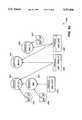
- FIG. 1is a block diagram of a network link controller according to the present invention.
- FIG. 2is a block diagram of a radio transceiver according to the present invention.
- FIG. 3is a block diagram of a digital controller according to the present invention.
- FIGS. 4, 5, 6a, and 6bare directed graph-process diagrams showing the operation of a control program according to the present invention.
- FIG. 7is a flowchart showing a first method of designating a master node.
- FIG. 8is a flowchart showing a second method of designating a master node.
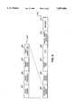
- FIG. 9shows an example of a data packet format according to the present invention.
- FIG. 10is a flow chart showing a Frequency Assignment Technique according to the present invention.
- FIG. 11is a flow chart showing a method of multipath management according to the present invention.
- a preferred embodiment of the inventionuses the microwave portion of the electromagnetic spectrum.
- Microwaveshave been found to have certain advantages over other portions of the spectrum.
- One major advantageis power efficiency.
- Microwaveshave relatively low path attenuation, permitting operation with transmitter power of less than 10 mW. The use of such low power transmitters reduces manufacturing costs.
- microwavesmay be reflected off various structures, and they do not suffer from the same degree of interference as do other portions of the electromagnetic spectrum.
- Link controller 100provides link level support for a network.
- Link level supportis defined as the first three layers of the seven-layer ISO network standard.
- Link level supportconsists generally of the physical layer (layer 1), data link (layer 2), and network layer (layer 3). These layers correspond to the bit, frame, and packet protocols, respectively.
- Link controller 100contains three major components: a radio transceiver 101, a digital controller 102, and a knowledge-based control program 103.
- a radiator 253(or antenna) is connected to link controller 100.
- transceiver 101operates at a frequency greater than 1 Gigahertz. In the preferred embodiment, transceiver 101 operates in the X Band (8.4 to 12.6 Gigahertz). Other frequencies may also be used.
- Radio transceiver 101includes a transmitter section (blocks 201 through 211) and a receiver section (blocks 212 through 216).
- the transmitter sectionoperates as follows. Two carrier generators 201 and 204 are used.
- Channel carrier generator 201generates channel carrier 255
- sub-band carrier generator 204generates sub-band carrier 259.
- Channel carrier 255provides multiple subchannels within the transmission band.
- Sub-band carrier 259provides multiple channels within a given subchannel.
- Each of the carrier generators 201 and 204contains a frequency-agile oscillator and is controlled by digital controller 102 using digital control lines 258 and channel select line 268.
- the three control lines 258permit eight different commands to be provided to the carrier generator.
- Channel carrier 255 generated by channel carrier generator 201is fed to data carrier generator 202.
- Data carrier generator 202uses channel carrier 255 along with a data synch clock 267 and data signal 257 containing raw data from a digital source (not shown) to synchronize the data to the carrier.
- a phase locked loopis employed, wherein a VCO is divided by a variable modulus divider and fed to a phase comparator. The phase comparator compares this signal with a reference oscillator. If the divider modulus is changed, the loop causes the VCO to change frequency until phase lock is established with the reference oscillator.
- the divider and reference oscillatormany different channels and sub-band sources may be generated. The sources thus generated are then converted up to the transmitter frequency, by any of a number of techniques known in the art, such as frequency multiplication or harmonic phase locking.
- the resultis data carrier 256 containing carrier-synchronized data.
- Data carrier 256is fed to data/bi-phase translator 203, which converts the mono-polar signal to a bipolar signal. The result is bipolar data carrier 261.
- harmonic phase detector 205uses the sub-band carrier 259 to excite a comb generator (not shown) that produces multiple harmonic frequencies. Harmonic phase detector 205 also accepts a signal from sub-band carrier voltage controlled oscillator (VCO) 206. VCO 206 operates at the fundamental output frequency of the transmitter.
- VCOsub-band carrier voltage controlled oscillator
- Harmonic phase detector 205compares the phase relationship between the signals from sub-band carrier generator 204 and VCO 206, and generates control signal 260 containing a DC voltage responsive to this comparison. If the relative phase is zero, then the DC voltage is null. If the relative phase is non-zero, then the DC voltage of control signal 260 is given a unique polarity corresponding to the phase relationship. Control signal 260 is then low-pass-filtered and fed to the voltage control input of VCO 206. Thus, a feedback loop between harmonic phase detector 205 and VCO 206 is established. This feedback loop forces VCO 206 to lock to a harmonic of the frequency of sub-band carrier 259. Any deviation from this phase lock results in a DC voltage on control signal 260 that causes VCO 206 to re-establish phase lock.
- phase modulator 208phase modulates the two signals.
- the systemmay operate with any number of phases, employing multi-phase modulation techniques that are well known in the art.
- phase modulator 208is fed to output amplifier 210, which is a gain-controllable wide band linear amplifier.
- the gain of amplifier 210is controlled by a control signal from RF power modulator 209.
- Power modulator 209generates this control signal in response to digital commands on transmitter power control line 262 from digital controller 102.
- digital commands 262are supplied along two lines, one for "power up” and one for “power down”.
- power modulator 209determines an appropriate power level and sends a signal to amplifier 210.
- Amplifier 210amplifies the signal from modulator 208 by the gain specified by power modulator 209, to produce amplified signal 263.
- Amplified signal 263is fed to forward directional coupler 211, which samples, rectifies, and low-pass filters the signal.
- the output of coupler 211is an analog DC of the relative power output of amplifier 210. This output is made available to digital controller 102 as a filtered DC signal, shown as antenna power level 266.
- the outputis also fed to circulator 252.
- Circulator 252feeds the output of coupler 211 to radiator 253.
- the purpose of circulator 252is to isolate the transmitted signal (going from coupler 211 to radiator 253) from the received signal (going from radiator 253 to filters 212), and also to match radiator 253 to the receiver and transmitter sections of transceiver 101.
- the receiver sectionoperates as follows.
- a received signal from radiator 253passes through circulator 252 and is sent to bandpass filters 212.
- Received power levelmay be increased or decreased in response to signals from controller 102.
- Filters 212pass all frequencies within the subcarrier frequency range, and exclude all out-of-band signals.
- the signalis then sent to mixer 216, which employs a direct conversion technique to extract data from the signal.
- direct conversionthe received signal has the same frequency as a local oscillator; combining the two signals produces a zero Intermediate Frequency (IF).
- Direct conversionis a general technique that is known in the art for application to single sideband, phase modulation, or amplitude modulation.
- the systemcan be substantially simplified by using limiting amplifiers and a digital logic discriminator. Such simplification limits the type of modulation that the receiver may accept, but it results in a relatively inexpensive device.
- a direct conversion receiverhas the following cost advantages: it does not require any crystal filters or ceramic filters; the number of coils required is limited; no need for IF tuning; only one frequency source (LO) needs to be set up and controlled, compared to three for a double-conversion superhet (2 LOs and a discriminator).
- a direct conversion receiverproduces a much simpler and less troublesome frequency response spectrum than a conventional superheterodyne receiver, due to the fact that a superhet may generate unwanted sum and difference frequencies for any number of inputs of the mixer.
- the output of the superhetmay contain higher-order detection products that may introduce unwanted spurious responses.
- the most significant such responseis image frequency, which can produce a difference frequency component.
- Direct conversionavoids these problems, because the IF is at such a low frequency that image rejection is essentially infinite and general IF leakage is essentially zero.
- the input datamay be sampled at twice the deviation frequency.
- direct conversion FSKis achieved as follows.
- the incoming signalafter: being filtered, is directed into two channels, where it is mixed in quadrature with the carrier frequency generated by VCO 206.
- the mixer output signalsare separated in phase by 90 degrees, and are at a frequency equal to the deviation of the incoming signal. Therefore, when they are combined, they cancel each other out, leaving the modulated data carrier 264.
- the inventioncould also be practiced with phase separations of less than or greater than 90 degrees.
- Modulated data carrier 264is fed to IF variable gain amplifier and band pass filters 213, which amplify and filter the signal.
- Band pass filters 213provide channel selectivity, while IF variable gain amplifier provides limiting so that the output can be regarded as digital waveforms.
- the variable gain of the amplifiermay be changed in response to receive gain control signal 272 that is generated by digital controller 102.
- band pass filters 213must pass the PSK frequency deviation while attenuating adjacent channel signals by approximately 60 dB.
- the amplified and filtered signalis fed to data phase detector 214 for digital demodulation.
- Data phase detector 214detects the lag or lead relationship among the channels, by comparing the phase of the signal with the phase of reference signal 254 from channel carrier generator 201, which does not contain any intentional phase modulation.
- Data phase detector 214is able to select among various frequencies in reference signal 254 in order to demodulate any of a number of channels of data for a given sub-band carrier.
- the received signal from 213is phase modulated by the received data. Thus, when these two signals are compared, the result is the recovered data base band.
- Phase detector 214outputs this data base band in NRZ format, in the form of DC signal 265, the amplitude of which is directly related to the phase relationship between the received signal and the reference signal.
- DC signal 265is fed to data shaper and output driver 215, which reconstruct the shape of the waveform according to techniques that are known in the art. Recovered data is sent along data out line 269. Data shaper and output driver 215 also may decrease the rise time and fall time of the waveform edges, and adjust output levels according to the requirements of the digital logic that output driver 215 feeds. Data clock recovery block 270 recovers a clock signal from the data, and transmits it on line 271.
- the base band of transceiver 101is adjusted by increasing or decreasing the DC bias voltage to a varactor. A greater voltage lowers the frequency, and a lesser voltage raises the frequency.
- Transceiver 101is able to provide several data channels. Each data channel is separated by approximately two times the bandwidth of the data.
- the transmitter section of transceiver 101selects a data channel by switching active elements in the resonating portion of the transmitter to move the center of the base band by the appropriate bandwidth offset. Since the IF is produced by combining the incoming signal with the transmitter frequency in mixer 216 (see above in connection with FIG. 2), the receiver is able to track the received signal.
- Radiator 253may be of any type known in the art, including an omni-directional lensing radiator or a slotted waveguide radiator.
- Multipathoccurs when radio frequency waves reflect from the surfaces of physical objects. These reflected waves may be redirected in a path that may differ from the path of the incident wave. Repeated reflections often result in a complex pattern of interfering reflected waves.
- a receiving antenna exposed to such a complex patternmay receive multiple instances of the same signal.
- the multiple instances of the signalare typically phase shifted with respect to each other, and attenuated to varying degrees, depending on the reflecting surface and the distance traveled.
- multipathmay present an interference problem in that it may be difficult to discriminate the primary signal from reflected signals. This problem is particularly evident in systems employing amplitude modulation.
- the preferred embodiment of the present inventionoperates in a wireless network that employs phase modulation, wherein average frequency over 360 degrees of conduction does not change. Only the instantaneous frequency is changed. Thus, the system is able to discriminate between two signals that are extremely close in frequency and amplitude. Generally, primary and reflected signals are very close in frequency, so that the difference frequency (the "beats" caused by interference between the signals) is low.
- FIG. 11there is shown a flow chart of a method of multipath management according to the present invention.
- the first packetis transmitted 1103.
- An oscillator in the receiveris phase-locked to the strongest of the primary or reflected signal 1104 with a slew rate or loop band pass filter that will not permit locking to the interfering signal.
- the primary and reflected signalsmay be readily distinguished from one another.
- the oscillatorlocks onto either the primary or the reflected signal, as either is a valid signal as long as they are not both processed at the same time. In fact, two (or more) signals may be processed alternately with no detrimental effect on signal quality.
- the system of the present inventionuses primary signals where possible, but is capable of switching to reflected signals when the primary signal is blocked or unavailable.
- the receiverOnce the receiver has attempted 1105 to receive the packet, it checks 1106 to see if reception was successful. If not, it switches 1107 either from a direct to a reflected signal path, or vice versa if it was already using a reflected path. The transmitting node then retransmits 1108 the packet, and the receiver again attempts 1105 to receive it. Once the packet is successfully received, the transmitter proceeds to transmit 1110 the next packet, and the process is repeated until there are no more packets.
- the device of the present inventionselectively reduces transmitted signal power using software control, as follows.
- the phase locked loopwill never lock on the reflected signal, since it always locks on the strongest first-received signal.
- the reflected signalwill never arrive before the direct signal, since reflections travel a greater distance. It is known that the signal power of a reflection is always less than 50% of the signal power of the direct signal.
- the systemcan ensure that only the direct signal is received and processed by reducing the transmit power level until the reflected signal is below the minimum detection level of the system.
- the phase locked loopwill lock only on the direct signal. If there is no direct signal, and only reflected signals exist, then the phase locked loop will lock on the strongest reflected signal.
- the transmitting nodeis responsible for adjusting power levels. Power levels are controlled and adjusted by digital controller 102 of the transmitting node, using digital feedback information found in the Sender State Records of the packet header, as described below.
- Each data packetis short enough to be transmitted faster than the radio frequency environment can impose changes that would cause the phase detector to lose its lock.
- the factors that generally cause loss of lockare physical movement of nodes, or a change in placement of solid objects. Such physical movement may be considered rapid in human terms, but is still slow enough for the system to avoid loss of lock.
- the phase detector of the receiverlocks onto the primary signal. After data block 20 has been received, the primary signal is obscured, so that only a reflected signal is of sufficient signal strength to be received and understood. The phase detector locks onto the reflected signal to the exclusion of the primary signal, so that even if the primary signal became available during transmission of data block 21 (or any subsequent data block), the receiver will maintain its lock on the reflected signal for the remainder of that block. As described above, if the reflected signal is interrupted during a data block, the transmitting node will re-transmit the block.
- a band pass filter with sharp cutoffis employed to attenuate the out-of-band signals sufficiently, so that they do not compete with the primary signal. This technique is successful only if the pass band is relatively narrow for the relationship between the primary signal and the reflected signal.
- Digital controller 102includes digital-to-analog and analog-to-digital converters, as well as digital I/O lines, all in block 501, to measure incoming signal strength, to provide voltages needed by the transmitter section of transceiver 101 to vary the power output of the transmitter section, and to select the channel.
- Converters 501accept power level data along line 266, and provide commands along transmitter power control line 262, receive gain control line 272 and channel select line 268.
- An 80286 microprocessor 502performs processing operations, using standard random-access memory (RAM) 503 and standard read-only memory (ROM) 504.
- Clocks 505generate clock signals for use by various parts of controller 102.
- Bus interface 506handles address decodes, commands, and timings between controller 102 and the computer to which it is attached (not shown).
- AT glue chip 507handles memory timings, implements DMA, PIC, timers, and the like, that make up an IBM AT.
- Bus latch 508latches data between local bus 509 and PC I/O bus 510. Local bus 509 ties together and allows communication among other components, while PC I/O bus 510 represents a standard bus for an IBM PC AT.
- Rec FIFO block 511receives incoming assembled byte/word data from I/O Decode block 517, and buffers high speed incoming data until CPU 502 checks for packet validity. Once :the check has been performed, block 511 empties the data into RAM 503.
- Receive control logic 512detects the start of headers, performs parity checks, detects packet errors and packet length, assembles byte/word data for Rec FIFO 511. Block 512 also contains FIFO strobe logic. Receiver shift register 513 accepts data on line 269 and clock on line 271, both from transceiver 101, and gates the bits.
- Xmit FIFO 514contains a packet to be transmitted.
- Xmit control logic 515generates the synch header, parity check, transmit enable, data synch clock out, and strobes for the FIFO and xmit shift register 516.
- Xmit shift register 516provides the serial data to transceiver 101 along line 257, synchronized with data synch clock out on line 267.
- I/O decode block 517provides the I/O address decoding for various output/input ports.
- Memory decode block 518is used for FIFO-to-memory and memory-to-FIFO operations.
- Shift register 513receives an incoming data signal from the Data Out line 269 of the receiver, also indicated as Serial In line 269 in FIG. 3. Shift register 513 also receives a data synch clock from recovered data clock line 271. Data is recovered from the data signal on line 269 by clocking the signal into shift register 513, and performing a pattern match to synchronize the incoming serial stream into discrete bytes. The bytes are then gated to Rec FIFO block 511 when the end of the synch header is reached, as is known in the art.
- Digital controller 102also contains firmware, which includes a small multi-tasking preemptive kernel:
- the kernelprovides a single-threaded process environment that allows inter-process communication and scheduling.
- the firmwareuses the process environment to facilitate a structured hierarchy of interrelated cooperative processes to minimize interrupt latency. Processes may wait for an event, pass messages through a monitor, share code, and delay themselves in process queues awaiting scheduling and/or resources. This methodology is well known in the art, and is described in Per Brinch Hansen, Concurrent Pascal Report, Information Science Department of the California Institute of Technology (1975).
- the monitoris a shared process resource that allows only one process at a time to access the code and data. Processes that invoke a monitor are blocked, and must wait in an entry queue for the current process in that monitor to leave or delay itself in a local monitor-controlled process queue.
- Class codeis shared among processes by making all process, monitor, and class code re-entrant.
- Class codeconsists of shared process routines that have their data instance in the declaring process. Monitor instances are part of the Initial Process (see below) and are outside the scope of all other processes.
- This processcontains three main parts: power up and self diagnostic test (POST), creation of multi-process data structures (monitors and processes), and creation and assumption of the identity of the currently running process.
- POSTpower up and self diagnostic test
- the POSTtests the integrity of the CPU, memory, controller circuits, interrupt controller, and setup for the download of the operating environment from either the host processor or the ROM file.
- the creation of multi-process data structuresconsists of a series of calls to initialize class, monitor, and process data structures. It also places the defined child processes in the ready queue and schedules these processes for execution.
- the Initial Processassumes the identity of each child for execution purposes.
- Init ProcessAllocates a stack and data area for a process stack. Passes the address of any and all monitors shared by that address. Sets the entry point for the process, and queues the process for execution.
- Init MonitorAllocates the private data area for the monitor and calls the initialization code of the monitor.
- Init ClassAllocates the private data area for the class, and calls the initialization code of the class.
- Enter MonitorSerializes entry to the monitor. If a process is already in the monitor, then the invoking process is queued in the monitor gate queue. Otherwise, the gate is closed.
- Leave MonitorEnters a process from the monitor gate queue in the ready queue. If no process is present in the monitor gate queue, then the monitor gate is opened.
- Resume ProcessThe process in the specified process queue variable is placed at the end of the monitor gate queue. This function is only allowed in a monitor.
- Delay ProcessThe process delays itself in the process queue variable specified. If the monitor gate queue is not empty, then the first process in the monitor gate queue is placed in the ready queue.
- I/O Interrupt ProcessA formless process that preempts the currently executing process either partially or fully.
- Ready QueueA threaded list of processes that are to be executed in first-in first-out (FIFO) sequence.
- Execute ProcessMaintains the currently executing process. Sets some global variables when invoked. When no child processes are running, the Initial Process is running.
- kernel 600there is shown a block diagram showing the structure of kernel 600, and its various elements. Each of the elements will be described in turn.
- Class P -- FIFO 601is a FIFO queue to hold background processes awaiting execution.
- Class T -- FIFO 602is a FIFO queue to hold processes awaiting expiration of a timer to resume execution.
- Class IO -- FIFO 603is a FIFO queue to hold processes awaiting certain input/output events.
- Monitor WAIT -- Q 604suspends and resumes processes held in class P -- FIFO 601, according to commands from process TIMER -- TASK 611.
- WAIT -- Q 604is used for primary time slice scheduling of background processes.
- Monitor READY -- Q 605is a FIFO queue of processes scheduled for execution.
- Monitor EXEC 606is the currently executing process.
- Monitor TIMER 607coordinates timer events and timer scheduling among interrupt process ALARM 610, interrupt process TICK 612, process TIMER -- TASK 611, and process IO -- TASKS 613. Monitor TIMER 607 suspends processes TIMER -- TASK 611 and IO -- TASKS 613 that use interrupt processes TICK 612 and ALARM 610 to resume execution for timings, fault determination, scheduling, and the like.
- Monitor IO 608schedules process IO -- TASKS 613 from interrupt process INT 614.
- BACKGROUNDS 609includes a number of processes that run periodically to monitor and/or control the system, including a simplex process, diagnostic process, and an awareness process. BACKGROUNDS 609 also includes the following processes:
- SPATIAL -- WATCHGauges vectors between nodes (ranging in effect). This process uses a linear algorithm, similar to simplex, to compare all internode signal strength pairs to generate a rough estimate of direction and distance.
- XMIT -- LEVEL -- WATCHPrepares data for the simplex algorithm. This process monitors changing signal strengths as found in received packet headers.
- NODE -- WATCHPrepares data for the simplex algorithm. This process monitors packets and notes when nodes have disappeared from the network.
- DIAGNOSTIC -- WATCHMonitors errors in packets and provides some information to the simplex algorithm.
- STATISTIC -- GATHEROrganizes node and system statistics for presentation to the PC in various formats.
- Interrupt process ALARM 610is a timeout interrupt generally used for long-term scheduling or for fault detection.
- Process TIMER -- TASK 611implements the coarse scheduling control of the system, and also handles the packet timeout/retry controls.
- Interrupt process TICK 612is a periodic timer input/output process.
- IO -- TASKS 613includes a number of processes that handle input/output operations. These processes use monitor IO 608 and monitor TIMER 607 to await "watchdog" interrupt events.
- Interrupt process INT 614is a generic formless interrupt process of the hardware.
- a key interrupt componentis a set of timers that perform message re-sending, status checking, and some process scheduling.
- timer interface 640according to the preferred embodiment of the present invention. It includes the following elements.
- Interrupt processes IOTICK 641 and IOALARM 642are equivalent to interrupt processes TICK 612 and ALARM 610, respectively. These interrupt processes are activated by interrupts and preempt the currently executing process. Once activated, they enter monitor TIME 643 and schedule process TIMER 644.
- Monitor TIME 643is equivalent to monitor TIMER 607.
- Process TIMER 644is equivalent to one of the processes in IO -- TASKS 613. It provides timed watchdog operation for various other processes through monitor WATCH 650.
- Process WATCHER 645is equivalent to one of the processes in IO -- TASKS 613. It coordinates data transfer to and from the PC, as well as transmit and receive data movement. It activates interrupt process ALARM 610 (for long-term events such as packet retransmission) and handles the short-term free-running timer ticks (for short-term events such as process RECEIVE -- DATA 647 and other I/O timeouts).
- Process REC -- TO -- PC 646is equivalent to one of the processes in IO -- TASKS 613. It handles received packets to the PC.
- Process RECEIVE -- DATA 647is equivalent to one of the processes in IO -- TASKS 613. It handles incoming data from Rec FIFO 511, filters the data, queues it for process REC -- TO -- PC 646, abstracts control information, and creates tables for use by some of the processes in BACKGROUNDS 609.
- Process XMIT -- DATA 648is equivalent to one of the processes in IO -- TASKS 613. It forms the data packets, loads Xmit FIFO 514, and enables the channel and transmit clock.
- Process XMIT -- FROM -- PC 649is equivalent to one of the processes in IO -- TASKS 613. It controls data coming from the PC.
- Monitor WATCH 650coordinates DMA, PC bus, and FIFO usages.
- FIG. 6athere is shown a transmit processing block 660 according to the present invention. It includes the following elements.
- Process XMIT -- FROM -- PC 649is equivalent to one of the processes in IO -- TASKS 613. It controls data coming from the PC.
- Monitor WATCH 650coordinates DMA, PC bus, and FIFO usages.
- Monitor PC -- BUS 661controls the access of PC I/O bus 510.
- Input/output process BUS -- ACT 662handles PC interrupts.
- Monitor DMA 663controls access to the DMA channel.
- DMA -- INT 664handles DMA terminal count interrupt.
- Process DMA -- XFER 665handles all DMA setups and terminations.
- Interrupt process XMIT -- INT 667is the transmit FIFO empty interrupt process.
- Monitor XMIT -- Q 668delays process XMIT -- DATA 648 pending an interrupt.
- FIG. 6bthere is shown a receive processing block 680 according to the present invention. It includes the following elements.
- Process REC -- TO -- PC 646is equivalent to one of the processes in IO -- TASKS 613. It handles received packets to the PC.
- Process RECEIVE -- DATA 647is equivalent to one of the processes in IO -- TASKS 613. It handles incoming data from Rec FIFO 511, filters the data, queues it for process REC -- TO -- PC 646, abstracts control information, and creates tables for use by some of the processes in BACKGROUNDS 609.
- Monitor WATCH 650coordinates DMA, PC bus, and FIFO usages.
- Input/output interrupt process CARRIER 681indicates receive data incoming.
- Monitor REC -- QUE 682controls the queuing of received data in FIFO and status results.
- the PC interface(not shown) includes processes sharing the DMA and register interface to the PC bus.
- the status and control registeris updated by a process, in order to ensure consistency (interrupts are off).
- the command registeris handled by a single process which activates the appropriate process to handle processes REC -- TO -- PC 646, XMIT -- TO -- PC (not shown), DIAGNOSTIC -- WATCH (part of BACKGROUNDS 609), and STATISTIC -- GATHER (part of BACKGROUNDS 609).
- the datais transferred to and from the PC via DMA from the local memory of link controller 100. Blocking occurs on these processes to allow serial access to the DMA channel.
- the register interfaceconsists of the following:
- the PC status/control interfaceis maintained by process DMA -- XFER 665. This process is activated by any of the following:
- the processthen sets the appropriate bits in the interface to generate an interrupt on the PC side.
- the PC status/control interfaceconsists of the following:
- the PCoperates on the interface by writing to the command register and setting bit 2 to alert the controller. After the controller has completed the command, it clears bit 2.
- the command registeraccepts a single byte as a command and additional data for the command through the data port. Return information is generated to the data port.
- the following tabledescribes the available commands:
- Reset RXFlushes all receive buffers. Activates any and all network resynch functions. Once completed, clears bit 5 in the status register.
- Reset TXFlushes all pending transmit buffers. Any pending buffers are considered lost, even if received at the other end. Forces a resynch with the network. Once completed, clears bit 6 in the status register.
- the local drivers in the PC at the nodemay instruct the user to perform some action in order to improve network communication.
- These instructionsmay be relatively simple operations that can be performed by any user, such as moving a radiator to a wall mount, or attaching a passive coupler to the ceiling.
- Packet datais transferred to local memory from the PC.
- Data format of the packet from the PCis:
- Packet datais queued in local memory.
- the PC driverdetermines the number and size of the queued packets from the Get Local Status fields.
- the PCissues the command, including number of packets, to get one or more packets.
- the PCgets the high part of the command byte, then awaits command complete status. Then, the PC reads the packets from the data port.
- Packet data formatis:
- Load ProgramInvokes the controller's loader. Optionally passes execution to the loaded program.
- Data formatis:
- the transmit processesform packets to be transmitted over the radio. Packets are obtained from the PC command process, formatted for sending, and are sent one packet at a time. Each packet is then queued in a hold queue, until one of the following occurs:
- ⁇ Acknowledgmentis received: packet is released. Required acknowledgment is specified in the packet control information from the PC.
- Timeoutoccurs: packet is retransmitted, unless the retransmit retry count is exhausted. When exhausted, the packet is released. The retransmit retry count is specified in the packet control information from the PC.
- the transmit processesoperate as follows:
- Process TRANSMITwaits in the XMIT -- DATA -- IN monitor for activation. It takes the passed packet, registers it, adds the header for the radio and adds it to the end of the FIFO stack in the XMIT -- MON monitor. It then registers the packet as being queued in the LOCAL -- STATUS monitor and re-enters the XMIT -- DATA -- IN monitor for more packets.
- SERIAL -- OUTwaits in the XMIT -- MON monitor for activation. Activation occurs when a packet is placed in the transmit FIFO stack by the TRANSMIT process, by the CARRIER -- INT -- IO, or by the SERIAL -- OUT -- FIFO -- INT activation. These processes activate SERIAL -- OUT and, depending on the type of activation, SERIAL -- OUT performs the following functions continuously:
- Process XMIT -- HOLDhandles the retransmissions. It is activated from the XMIT -- WAIT monitor by either an acknowledgment or by a TIMER -- ALERT signal from the timer subsystem. If timeout retry is requested for a packet in the holding queue, then the packet is resubmitted to the XMIT -- MON monitor. If retries are exhausted, then the packet is released and LOCAL -- STATUS is posted for error. If acknowledgment is requested and received, then LOCAL -- STATUS is updated with the proper completion code. If no acknowledgment is requested, then the packet is released and LOCAL -- STATUS is updated appropriately.
- Serial-In to Packet DataThe process checks the length of the packet and other error indications to verify packet integrity. If the packet is found to be valid, system information is registered and if the packet is for this node, it is passed to process REC -- TO -- PC 646.
- Incoming datais received from the FIFO stack via DMA channel to local memory.
- an interruptis generated.
- Control program 103is a state machine that monitors the state of digital controller 102 to which it is connected. When the state of digital controller 102 changes, control program may issue commands regarding reconfiguration of the network.
- control program 103consists of a knowledge-based expert system, including an inference engine and a set of rules.
- the inference engineaccepts a set of input data representing a state description.
- input datamay include, for example:
- node identifiersnode identifiers, network identifiers, ranges of DACs, packet formats for node communication, sub-network definitions;
- Event descriptionscommunication attempts between one node and another, responses to queries, adjustment of operating parameters
- Performance datadata throughput measurements, signal strength, unacknowledged packets indicating loss of communication
- Meta-knowledgemeasured information on average signal strength as related to distance, multipath characterizations, obstacle insertion and removal, types of signal loss, likelihood of noise band avoidance by moving base band.
- one set of rulesmay be designated for application to certain configurations (such as a factory installation, where there is a great deal of steel near the network), while,another set of rules may be designated for other configurations (such as a conventional office installation).
- Rule pruningmay also occur, according to techniques known in the art, to simplify or limit the number of rules.
- ⁇ Factif two or more power levels are found to node X, then an intermittent obstacle exists
- ⁇ Meta-rulefirst try low power, then high power; also, determine hit frequency on low power; if hit frequency is greater than a certain percentage, then reverse the rule, to first try high power, then low power
- the inference engineapplies the rule set to the state description corresponding to the current state of the network, and generates a set of outputs corresponding to reconfiguration commands for the network.
- the control programmay permit addition, deletion, or modification of the rules.
- the enginetypically uses goal-oriented backtracking recursive descent algorithms, as are known in the art.
- the rulestypically consist of a series of "if then” statements, and are interpreted using forward chaining methodology. State descriptions may be defined in terms of probabilities associated with the defined goals of the inference engine. Thus, a technique known as "fuzzy" logic may be implemented.
- the knowledge-based systemis used to reduce the input data set to a set of relatively few outputs. Each output forms a series of commands to be applied to the network. In some situations, where more than one output set is generated, indicating more than one possible configuration for the network, the system may try each of the outputs, apply a performance metric to measure the relative success of the configuration, and feed back the results of the performance metric to the knowledge-based system's rule set in order to refine the configuration process.
- the control program 103including the knowledge-based system, provides the link level support for the network.
- the control programrequires that one node's digital controller 102 be designated as the master.
- the masterdictates the frequency used in the network to the other controllers 102.
- Other controllers 102adjust their frequencies to match that of the master. Frequency adjustment is accomplished in a conventional manner by changing a DC bias on the "cavity" resonator using a digital-to-analog converter (DAC) under the control of the software. By performing such adjustments, the network compensates for frequency drift.
- DACdigital-to-analog converter
- the present inventionemploys an inexpensive method of frequency control wherein a common communication frequency is established by a master and followed by all other controllers 102.
- This methodprovides the ability to easily move the frequency to another band in order to avoid noise and interference with other networks or communication bands.
- the methodalso facilitates establishment of a secondary communication frequency for a designated portion of the network. This secondary communication frequency is accomplished using a second tuned "cavity" that is switchable under software control.
- the initialization process for each digital controller 102consists of two parts: power-on self test, and node insertion into the network.
- the power-on self testperforms standard controller integrity checks (including ROM, RAM, control section verification, and radio checkout).
- the node insertion stepconsists of listening to the controller's own traffic to establish that the radio section is operating properly.
- each controller 102After initialization, each controller 102 must determine whether it will become the master.
- the systemmay use one of two methods to determine a master.
- the networkdesignates 702 a specific link controller as an initial master, usually based on a selection that is made by a system administrator upon installation.
- a status bit in the packet headeris set 703 to indicate the status of the master, and the packet header is transmitted 704.
- All the other controllers 102scan their frequency range 705 and lock onto the master.
- the frequency range of each controller 102is defined by the allowable variance in the DC bias to the DAC that controls the base band.
- the controllersrecognize the master by checking the relevant status bit in the received packet. Once the other controllers 102 have locked onto the master 706, they track the master as described above, and set their frequency range 707 to match the master.
- This methodinvolves a controller selection process to be performed across all of the controllers in the network.
- the controllerevery time a controller is initialized, the controller must determine whether it will become the master. To make this determination, the controller performs the following steps.
- a master -- sync packetis a packet wherein the master bit within the Sender State Status Byte is set, indicating that the sender has designated itself as the master (see Data Protocols, below). All other data in the packet is the same as for a typical controller data packet, including, optionally, a user-defined portion.
- the controllerfinds a master -- sync packet, that means that one of the controllers in the system has already been designated as the master.
- the scanning controllermatches 804 to the master's frequency and sends the master a "link controller ready" packet. If no master -- sync packet is found, the controller selects 806 the midpoint of its frequency range and begins transmitting a master -- sync packet 807 at that frequency. Thus, the controller designates itself as the master.
- a masterreceives a master -- sync packet from another controller, it waits for a period of time (the time period may depend on past history information regarding the network) and performs the initialization process again.
- This proceduretakes place under the direction of the control program, which includes rules governing master selection.
- rulesinclude: minimization of signal power while maintaining contact with all nodes; maximization of uptime (the amount of real time that the node is operational); minimization of multipath to nodes; preference for stability based on past history information regarding previous designations of master nodes; and maximization of node uptime as a percentage of network uptime. Since all nodes share the same information and rules, all nodes are capable of arriving at the same decision as to which will be the master. Thus, simultaneous designation of more than one master is avoided.
- the mastercan change the network frequency as required. Typically, the frequency may need to be changed due to interference, noise, or other factors.
- the masteremploys a Frequency Assignment Technique (FAT).
- FATFrequency Assignment Technique
- step 1001the process begins.
- step 1002the master determines a new frequency for the network based on availability, interference, levels, and other factors.
- step 1003the master transmits a new -- frequency packet announcing the new frequency to all the link controllers in the network.
- the packet header for this packetalso includes a byte indicating the power level at which the packet was sent.
- the link controllersOnce the link controllers receive the packet, they change to the new frequency in step 1004. All frequency changes are accomplished either by changing the DC bias value in the DAC to the "cavity" resonator, or by selecting another "cavity".
- the masterperforms adjustments to the network by selecting optimal power levels for each link controller.
- step 1005the master selects a link controller. Then, in step 1006, the master transmits a change -- power packet to that link controller. In step 1007, the link controller changes its power level in response to the change -- power packet, and in step 1008 it sends a new -- power -- ack packet back to the master, indicating acknowledgment of the change -- power packet. In step 1009, the master measures the signal strength of the received new -- power -- ack packet. In step 1010, the master determines whether the signal strength is optimal. This determination is made according to the simplex algorithm, a well-known linear programming technique that describes the magnitude and sign of the changes to be made in order to optimize the received signal strength.
- the Simplex algorithmspecifies the threshold for convergence at the optimal value of signal strength, and specifies methods for determining whether the converged value is the true optimal value or an artifact of errors in the data.
- the simplex algorithmis described in S. I. Gass, Linear Programming Methods and Applications, 2d ed., New York: McGraw-Hill, 1964; G. Hadley, Linear Programming, Reading, Mass.: Addison-Wesley, 1962; and A. F. Carley and T. H. Morgan, "Computational Methods in the Chemical Sciences”: Chichester, Ellis Horwood Limited, 1989.
- variablesare described by a value, range, and statistical range. Variables may represent signal level settings, vector values (for spatial data), message counts, and Boolean values. To perform the simplex algorithm, a matrix is constructed using known values for the variables, selected variables are relaxed, and the matrix is solved to obtain the optimal signal strengths for the various nodes.
- Each nodeselects its power levels as follows. Included in each node's Sender State Records is the lowest power level, plus a reasonable margin, that the transmitting node saw. Since background traffic (such as heartbeats, acknowledgments, and the like) is often continually present, and since the control program is instructed, at first, to vary the power level for the node to establish these optimal power levels, the system quickly establishes its internode transmit power levels. If communication is lost between two nodes (for example, when obstacles appear, indicating a need for multipath), then further communication attempts are made using the highest available power settings. If communication cannot be established at these high levels, and other nodes also indicate that the node has disappeared, it is presumed to be powered off. Otherwise, a relay is set up to allow access to the node.
- steps 1006 through 1010are repeated until the link controller is transmitting at an optimal power level. Then, in step 1011, the master checks to see if there are any more link controllers to be adjusted. The master repeats steps 1006 through 1011 for each link controller. Then, in step 1012, the master selects a minimal optimal signal strength for itself.
- the power level of each node of the networkis at a minimum optimal level.
- FATallows the master to change the network frequency to avoid noise and interference, and to automatically adjust power levels for the new frequency.
- FATprovides the following advantages:
- Work groupsare known in the art.
- Conventional wire adaptersimplement work groups by logically tying together two separate Ethernet cabling systems, each with a separate adapter.
- the present inventionprovides for a single adapter dynamically handling a number of distinct networks. Any adapter may participate in any of the separate networks. This provides improved flexibility and increased system performance.
- Each nodecan periodically monitor each of the separate networks under user and/or node control.
- Each such work groupoperates at a different frequency and with its own master.
- ⁇Increased network security by preventing unauthorized nodes from connecting to the network.
- User-specified encryption keys for node and system accesscan be monitored to prevent connection of duplicate or foreign nodes.
- the systemmay use power level information to ascertain by triangulation the position of each node. By exchanging this information among nodes, by way of a special "user" packet, the system is made aware of spatial relationship among nodes. Appearance of a node whose position does not accord with this spatial relationship may indicate the presence of an intruding node, so that a supervisor or administrator may be notified.
- the systemmay encrypt packets and employ the frequency-agility of the network to implement pseudo-random channel hopping in order to make it more difficult for unauthorized users to connect to the network.
- FIG. 9shows an example of a data packet format according to the present invention, including link controller header 900.
- link controller header 900As will be apparent to those skilled in the art, other protocols and formats may also be used in connection with the present invention.
- link controller header 900includes the following items: synch header 901, digital frequency 902, sender state 903, and synch header CRC 904.
- the information in link controller header 900describes the node sending the packet, and the view of the network seen by the sending node.
- Synch header 901is used to indicate the start of a packet.
- synch header 901consists of seven bytes of the binary value 10101010 followed by 10101011.
- Digital frequency 902is a two-byte field that specifies the number of bytes in the packet. It also specifies the frequency of the node that is transmitting the packet. Thus, digital control of frequency is accomplished by counting the number of bytes received in the packet and comparing this count against the value of digital frequency 902. If the counted number is less than the value of digital frequency 902, then the base band (controlled by the DAC as described above) must be adjusted downwards; if the counted number is more, then the frequency must be adjusted upwards. The adjustment is performed by the transceiver 101 as described previously.
- the DAC valueis 1000, and the number of bytes received in the packet is more than 1000, the DAC value is increased, for example to 1100. If the number of bytes received is less than 1000, the DAC value is decreased, for example to 920.
- Sender state 903contains information describing the node that is transmitting the packet, and its view of the network. This information is used by the receiver of the packet in order to update packet counts and traffic information.
- Sender state 903consists of a Sender State Status Byte (indicating such information as whether the transmitter is a Master, or attempting to find a master, its unit type, and whether it is a relay point), a Sender State Count Byte indicating the number of sender state records that are to follow (from 0 to 10), and the sender state records themselves. In some cases, there will be no sender state records.
- Each sender state recordcontains the following:
- Sender state 903further contains information about current packet number received from that node and the current send packet number.
- Each directed packethas a sequence number (modulo 256) included in it.
- Synch header CRC 904is a 16-bit field containing a value that is derived, according to techniques known in the art, from the values of the other fields in header 900. It serves as a validation check to ensure that the information contained in all the fields is correct.
- Data packet 905 in the preferred embodimentincludes the following items: link controller header 900, packet header 906, packet type 907, data 908, packet error detection 909, and epilogue 910.
- Link controller header 900describes the node sending the packet, and is identical to that described above.
- Packet header 906contains information describing the packet, its destination node, and its source node. It contains six bytes specifying the destination node address, six bytes specifying the source node address, and two bytes specifying the packet length.
- Packet type 907describes the type of data in the packet. It is user-defined, and is one byte in length.
- Data 908is the actual data being transmitted. Its length may range from zero bytes to 1594 bytes.
- Packet error detection 909is a four-byte field employing standard ECC multiple bit error detection methodology to verify the validity of the preceding fields.
- Epilogue 910contains packet termination information. It consists of two bytes containing the binary pattern 00110011.
- the data packet as a wholecontains the following fields:
Landscapes
- Engineering & Computer Science (AREA)
- Computer Networks & Wireless Communication (AREA)
- Signal Processing (AREA)
- Evolutionary Computation (AREA)
- Computer Vision & Pattern Recognition (AREA)
- Databases & Information Systems (AREA)
- Artificial Intelligence (AREA)
- Medical Informatics (AREA)
- Software Systems (AREA)
- Mobile Radio Communication Systems (AREA)
- Use Of Switch Circuits For Exchanges And Methods Of Control Of Multiplex Exchanges (AREA)
- Vehicle Body Suspensions (AREA)
- Eye Examination Apparatus (AREA)
- Data Exchanges In Wide-Area Networks (AREA)
- Communication Control (AREA)
Abstract
Description
______________________________________ Register Type Offset Use ______________________________________ Status Read/write 0 Error indication, interrupt and byte conditions pending, interface Control busy, interrupt status Com- Write byte 1 Command to perform mand Read/write 2 Data in and data out (configura- Data word tion, received packets, trans- mitted packets, and the like) ______________________________________
______________________________________ Bit # Use ______________________________________ 0 Reserved, reads 0 1 Read 1; reset controller (hard reset, enters boot sequence, all local controller memory lost, all status bits cleared); dear to 0 when finished with reset 2 Read 1; perform command; clear to 0 when command finished 3 Reserved, reads 0 4 Write 1 when fatal (irrecoverable) error occurs; error code is placed in data port 5 Write 1 when transmit packet operation complete; write 0 when transmit packets status read ("get local status" command complete) 6 Write 1 when receive packet pending; write 0 when an receive packets read and/or flushed ("get local status" command complete) 7 Write 1 to enable interrupts to PC; clear to 0 to disable interrupts ____________________________________________________________________________ Command Value Description ______________________________________ No Operation 0 Do nothing; no return value Reset All 1 Reset entire controller Reset RX 2 Reset receiver hardware and processes Reset TX 3 Reset transmitter hardware and processes Get Local 4 Get local controller status Status Get Net Status 5 Get network status tables Transmit 0xN6 Transmit N packets (N ranges from 1 Packet(s) to 15) Receive 0xN7 Receive N packets (N ranges from 1 Packet(s) to 15) Load Program 8 Load program to process Write Memory 9 Write data to specified memory area Read Memory 1-10 Read specified memory to interface ______________________________________
______________________________________ # of Bytes Description ______________________________________ 2 Length in bytes of remaining fields 1 Number of transmit packet records (N) 3*N Transmit packet records. The first two bytes in each record is the ID as set in the transmit packet; the third byte is the status 1 Number of receive packet records (M) 2*M Receive packet records. ______________________________________
______________________________________ # of Bytes Description ______________________________________ 6 This Node ID (MU 802.3 style) ______________________________________
______________________________________ # of Bytes Description ______________________________________ 2 Length in bytes of remaining fields 2 Transmit packet ID (used for return status) 2 Transmit control word 6 Destination node ID (IEEE 802.3 standard) 6 Source node ID (IEEE 802.3 standard; filled in by controller) 2 Length of packet in bytes (N) 1 Type of packet N 0 to 1590 bytes of user data ______________________________________
______________________________________ # of Bytes Description ______________________________________ 6 Destination node ID (IEEE 802.3 standard) 6 Source node ID (IEEE 802.3 standard; filled in by controller) 2 Length of packet in bytes (N) 1 Type of packet N 0 to 1590 bytes of user data ______________________________________
______________________________________ # of Bytes Description ______________________________________ 2 Length in bytes of remaining fields 4 Load address (offset: segment form) 4 Starting address (0xFFFF; load only option) 2 Number of relocation offsets (N) 2*N Relocation offsets M Loaded program ______________________________________
______________________________________ # of Bytes Description ______________________________________ 2 M bytes of remaining fields 4 Write memory start (offset: segment form) 2 Number of bytes of data to be written ______________________________________
______________________________________ # of Bytes Description ______________________________________ 2 Length in bytes of remaining fields 4 Read memory start (offset: segment form) 2 Number of bytes of data to be read ______________________________________
______________________________________ Value Description ______________________________________ 0 Operation OK 1 Command not recognized 2 Insufficient memory for operation 3 Data format error 4 POST - ROM checksum error 5 POST - RAM integrity error 6 POST - FIFO error 7 POST - Control circuitry error 8 POST - Radio self test error 80 Packet sent and (optionally) received 81 Packet queued for sending 82 Packet being sent 83 Packet send time out 84 Packet destination not responding ______________________________________
__________________________________________________________________________Field Name Size (bytes) Description __________________________________________________________________________Synch header 901 8 Synchronization bit stream for packet start (seven bytes of 10101010 followed by one byte of 10101011). Digital frequency 2 Length of the datapacket excluding Synch 902 Header. Used to adjust frequency oftransceiver 101. Sender state status 1 Bit 0: Indicates whether sender is master byte Bit 1: Indicates whether trying to establish a master Bit 2: Indicates whether network has lost master Bit 3: Indicates whether sender is being as a relay Bits 4-7: Reserved for future use Sender state count 1 Number of sender state records following. byte Sender state 8*n Four bytes indicating unique identification records code; one byte of power control informa- tion; one byte of frequency drift factor; one byte of frequency control information; one byte of packet receive and transmit status. n is user-selectable, from 0 to 10. Synch header CRC 1 CRC forlink controller header 904Packet header 906 14 Six bytes of destination node address; six bytes of source node address; two bytes of length.Packet type 907 1 User-defined. Data 908 m User-defined. m may range from zero to 1594. Packet error detec- 4 Standard ECC error detection.tion 909Epilogue 910 2 Packet termination. Two bytes of 00110011. __________________________________________________________________________
Claims (25)
Priority Applications (1)
| Application Number | Priority Date | Filing Date | Title |
|---|---|---|---|
| US08/395,206US5551066A (en) | 1993-06-07 | 1995-02-27 | Network link controller for dynamic designation of master nodes |
Applications Claiming Priority (2)
| Application Number | Priority Date | Filing Date | Title |
|---|---|---|---|
| US7204293A | 1993-06-07 | 1993-06-07 | |
| US08/395,206US5551066A (en) | 1993-06-07 | 1995-02-27 | Network link controller for dynamic designation of master nodes |
Related Parent Applications (1)
| Application Number | Title | Priority Date | Filing Date |
|---|---|---|---|
| US7204293AContinuation | 1993-06-07 | 1993-06-07 |
Publications (1)
| Publication Number | Publication Date |
|---|---|
| US5551066Atrue US5551066A (en) | 1996-08-27 |
Family
ID=22105202
Family Applications (2)
| Application Number | Title | Priority Date | Filing Date |
|---|---|---|---|
| US08/262,562Expired - LifetimeUS5530701A (en) | 1993-06-07 | 1994-06-20 | Network link controller |
| US08/395,206Expired - LifetimeUS5551066A (en) | 1993-06-07 | 1995-02-27 | Network link controller for dynamic designation of master nodes |
Family Applications Before (1)
| Application Number | Title | Priority Date | Filing Date |
|---|---|---|---|
| US08/262,562Expired - LifetimeUS5530701A (en) | 1993-06-07 | 1994-06-20 | Network link controller |
Country Status (10)
| Country | Link |
|---|---|
| US (2) | US5530701A (en) |
| EP (1) | EP0654196A1 (en) |
| AU (1) | AU7055594A (en) |
| BR (1) | BR9405417A (en) |
| CA (1) | CA2141613A1 (en) |
| CZ (1) | CZ58095A3 (en) |
| FI (1) | FI950527L (en) |
| HU (1) | HUT71564A (en) |
| PL (1) | PL307357A1 (en) |
| WO (1) | WO1994029986A1 (en) |
Cited By (80)
| Publication number | Priority date | Publication date | Assignee | Title |
|---|---|---|---|---|
| US5828660A (en)* | 1996-04-26 | 1998-10-27 | Motorola, Inc. | Multiple user communication system, device and method with overlapping uplink carrier spectra |
| US5949777A (en)* | 1994-05-03 | 1999-09-07 | George Uyesugi | Wireless communication processor system |
| US6026303A (en)* | 1996-11-07 | 2000-02-15 | Nec Corporation | Method for determining optimal parent terminal and ad hoc network system for the same |
| US6044335A (en)* | 1997-12-23 | 2000-03-28 | At&T Corp. | Productivity metrics for application software systems |
| US6061794A (en)* | 1997-09-30 | 2000-05-09 | Compaq Computer Corp. | System and method for performing secure device communications in a peer-to-peer bus architecture |
| US6122514A (en)* | 1997-01-03 | 2000-09-19 | Cellport Systems, Inc. | Communications channel selection |
| US6175770B1 (en) | 1997-12-31 | 2001-01-16 | Dana Corporation | Electronic controller having automatic self-configuration capabilities |
| US6178444B1 (en)* | 1996-03-11 | 2001-01-23 | Kabushiki Kaisha Toshiba | System and method that prevent messages transferred among networked data processing systems from becoming out of sequence |
| US20010012757A1 (en)* | 2000-02-03 | 2001-08-09 | U.S. Philips Corporation | Ad-hoc radio communication system |
| US20020073257A1 (en)* | 2000-12-07 | 2002-06-13 | Ibm Corporation | Transferring foreign protocols across a system area network |
| US6434113B1 (en)* | 1999-04-09 | 2002-08-13 | Sharewave, Inc. | Dynamic network master handover scheme for wireless computer networks |
| US20020115458A1 (en)* | 2001-02-21 | 2002-08-22 | Nippon Telegraph And Telephone Corporation | Radio communication system |
| US20020126694A1 (en)* | 2000-12-28 | 2002-09-12 | Mika Kahola | Method for performing link adaptation |
| US6480975B1 (en)* | 1998-02-17 | 2002-11-12 | International Business Machines Corporation | ECC mechanism for set associative cache array |
| US6493777B1 (en)* | 1999-09-15 | 2002-12-10 | Lucent Technologies Inc. | Method for dynamically reconfiguring data bus control |
| US20030018805A1 (en)* | 2001-06-29 | 2003-01-23 | International Business Machines Corporation | Automated configuration enabled via interrogation over network |
| WO2002021704A3 (en)* | 2000-09-08 | 2003-09-12 | Pricer Ab | Power margin control |
| US20040025063A1 (en)* | 2002-07-31 | 2004-02-05 | Compaq Information Technologies Group, L.P. A Delaware Corporation | Power management state distribution using an interconnect |
| US6694141B1 (en)* | 1997-06-24 | 2004-02-17 | Nokia Networks Oy | Channel selection in a radio link system |
| US20040075692A1 (en)* | 2000-10-03 | 2004-04-22 | Bruce Matichuk | Application integration system and method using intelligent agents for integrating information access over extended networks |
| US6735447B1 (en)* | 1999-12-08 | 2004-05-11 | Telefonaktiebolaget Lm Ericsson (Publ) | Transmission power control of a mobile station |
| US6744752B1 (en)* | 1999-10-05 | 2004-06-01 | Koninklijke Philips Electronics N.V. | Radio local area network |
| US20040117433A1 (en)* | 1995-07-21 | 2004-06-17 | Walpert Gary A. | Cooperative computer network |
| US20040185842A1 (en)* | 2003-01-28 | 2004-09-23 | Spaur Charles W. | Secure telematics |
| US20040266443A1 (en)* | 2003-06-30 | 2004-12-30 | Takafumi Ito | Radio communication device and a method for establishing radio connection |
| US20050050249A1 (en)* | 2003-08-29 | 2005-03-03 | Kenichi Ide | Communication device and a method for establishing communication connection |
| US20050058114A1 (en)* | 2003-09-15 | 2005-03-17 | John Santhoff | Ultra-wideband communication protocol |
| US20050058153A1 (en)* | 2003-09-15 | 2005-03-17 | John Santhoff | Common signaling method |
| US20050083863A1 (en)* | 2003-10-16 | 2005-04-21 | Toshitomo Umei | Data transmission apparatus and data transmission system, and initialization method thereof |
| US20050096015A1 (en)* | 2003-10-31 | 2005-05-05 | Kazunori Aoyagi | Information processing system with communication device communicating with outside device |
| US20050094838A1 (en)* | 2003-10-31 | 2005-05-05 | Ichiro Tomoda | Electronic device with wireless communication module |
| US6907257B1 (en)* | 1999-11-10 | 2005-06-14 | International Business Machines Corporation | Method and apparatus for searching for radio station for wireless ad hoc communication network |
| US20050174950A1 (en)* | 2004-02-09 | 2005-08-11 | Sharp Laboratories Of America, Inc. | Distributed network organization and topology discovery in ad-hoc network |
| US6941350B1 (en) | 2000-10-19 | 2005-09-06 | International Business Machines Corporation | Method and apparatus for reliably choosing a master network manager during initialization of a network computing system |
| US20050245272A1 (en)* | 2004-04-29 | 2005-11-03 | Spaur Charles W | Enabling interoperability between distributed devices using different communication link technologies |
| US6978300B1 (en) | 2000-10-19 | 2005-12-20 | International Business Machines Corporation | Method and apparatus to perform fabric management |
| US6981025B1 (en)* | 2000-10-19 | 2005-12-27 | International Business Machines Corporation | Method and apparatus for ensuring scalable mastership during initialization of a system area network |
| US6990528B1 (en) | 2000-10-19 | 2006-01-24 | International Business Machines Corporation | System area network of end-to-end context via reliable datagram domains |
| US20060030318A1 (en)* | 2004-07-30 | 2006-02-09 | Steve Moore | Common signaling method and apparatus |
| US20060031429A1 (en)* | 2004-08-06 | 2006-02-09 | Sharp Laboratories Of America, Inc. | Central coordinator selection in ad hoc network |
| US20060036790A1 (en)* | 2004-08-10 | 2006-02-16 | Peterson Beth A | Method, system, and program for returning attention to a processing system requesting a lock |
| US20060036782A1 (en)* | 2004-08-10 | 2006-02-16 | Peterson Beth A | Method, system, and program for managing path groups to an input/output (I/O) device |
| US20060121851A1 (en)* | 2004-12-06 | 2006-06-08 | Steve Moore | Ultra-wideband security system |
| US7099955B1 (en) | 2000-10-19 | 2006-08-29 | International Business Machines Corporation | End node partitioning using LMC for a system area network |
| US7113995B1 (en) | 2000-10-19 | 2006-09-26 | International Business Machines Corporation | Method and apparatus for reporting unauthorized attempts to access nodes in a network computing system |
| US20070014331A1 (en)* | 2005-07-12 | 2007-01-18 | John Eldon | Ultra-wideband communications system and method |
| US20070014332A1 (en)* | 2005-07-12 | 2007-01-18 | John Santhoff | Ultra-wideband communications system and method |
| US7280530B2 (en) | 1997-07-25 | 2007-10-09 | Starvox Communications Inc. | Apparatus and method for integrated voice gateway |
| US20080010296A1 (en)* | 2002-11-14 | 2008-01-10 | Seisint, Inc. | System and method for configuring a parallel-processing database system |
| US20080049716A1 (en)* | 2006-06-30 | 2008-02-28 | Intel Corporation | Error rate based power management of a high-speed serial link |
| US20080195306A1 (en)* | 2005-06-15 | 2008-08-14 | Airbiquity Inc. | Remote destination programming for vehicle navigation |
| US20080212651A1 (en)* | 2003-09-15 | 2008-09-04 | John Santhoff | Communication protocol |
| US20090022095A1 (en)* | 2007-07-16 | 2009-01-22 | Cellport Systems, Inc. | Communication Channel Selection and Use |
| US20090061778A1 (en)* | 2006-03-20 | 2009-03-05 | Nortel Networks Limited | Method and system for fractional frequency reuse in a wireless communication network |
| US20090154444A1 (en)* | 2005-01-31 | 2009-06-18 | Airbiquity Inc. | Voice channel control of wireless packet data communications |
| US7636772B1 (en) | 2000-10-19 | 2009-12-22 | International Business Machines Corporation | Method and apparatus for dynamic retention of system area network management information in non-volatile store |
| US20100067565A1 (en)* | 2008-09-15 | 2010-03-18 | Airbiquity Inc. | Methods for in-band signaling through enhanced variable-rate codecs |
| KR100961785B1 (en) | 2008-02-28 | 2010-06-07 | 한양대학교 산학협력단 | Sensor network system to reselect cluster head nodes |
| NL1036326C2 (en)* | 2008-12-18 | 2010-06-21 | Thales Nederland Bv | Method for selecting a relay node in a wireless communication system. |
| US7747281B2 (en) | 1997-05-19 | 2010-06-29 | Airbiquity Inc. | Method for in-band signaling of data over digital wireless telecommunications networks |
| US7924934B2 (en) | 2006-04-07 | 2011-04-12 | Airbiquity, Inc. | Time diversity voice channel data communications |
| US7979095B2 (en) | 2007-10-20 | 2011-07-12 | Airbiquity, Inc. | Wireless in-band signaling with in-vehicle systems |
| US8046362B2 (en) | 2008-04-24 | 2011-10-25 | Lexisnexis Risk & Information Analytics Group, Inc. | Statistical record linkage calibration for reflexive and symmetric distance measures at the field and field value levels without the need for human interaction |
| US8068792B2 (en) | 1998-05-19 | 2011-11-29 | Airbiquity Inc. | In-band signaling for data communications over digital wireless telecommunications networks |
| US8073440B2 (en) | 2009-04-27 | 2011-12-06 | Airbiquity, Inc. | Automatic gain control in a personal navigation device |
| US8090733B2 (en) | 2008-07-02 | 2012-01-03 | Lexisnexis Risk & Information Analytics Group, Inc. | Statistical measure and calibration of search criteria where one or both of the search criteria and database is incomplete |
| US8188709B2 (en)* | 2008-01-09 | 2012-05-29 | Seiko Epson Corporation | Power transmission control device, power transmitting device, non-contact power transmitting system, and electronic instrument |
| US20120185583A1 (en)* | 2011-01-19 | 2012-07-19 | Qualcomm Incorporated | Methods and apparatus for enabling relaying of peer discovery signals |
| US8249865B2 (en) | 2009-11-23 | 2012-08-21 | Airbiquity Inc. | Adaptive data transmission for a digital in-band modem operating over a voice channel |
| US8418039B2 (en) | 2009-08-03 | 2013-04-09 | Airbiquity Inc. | Efficient error correction scheme for data transmission in a wireless in-band signaling system |
| USRE44487E1 (en)* | 2006-12-13 | 2013-09-10 | Globalfoundries Inc. | Command packet packing to mitigate CRC overhead |
| US8594138B2 (en) | 2008-09-15 | 2013-11-26 | Airbiquity Inc. | Methods for in-band signaling through enhanced variable-rate codecs |
| US8848825B2 (en) | 2011-09-22 | 2014-09-30 | Airbiquity Inc. | Echo cancellation in wireless inband signaling modem |
| US8965291B2 (en) | 2010-07-13 | 2015-02-24 | United Technologies Corporation | Communication of avionic data |
| US9015171B2 (en) | 2003-02-04 | 2015-04-21 | Lexisnexis Risk Management Inc. | Method and system for linking and delinking data records |
| US9189505B2 (en) | 2010-08-09 | 2015-11-17 | Lexisnexis Risk Data Management, Inc. | System of and method for entity representation splitting without the need for human interaction |
| US9411859B2 (en) | 2009-12-14 | 2016-08-09 | Lexisnexis Risk Solutions Fl Inc | External linking based on hierarchical level weightings |
| US9444891B2 (en) | 2013-07-01 | 2016-09-13 | Emoire Technology Development LLC | Data migration in a storage network |
| US10939308B2 (en) | 2019-03-14 | 2021-03-02 | Cisco Technology, Inc. | Deploying network functions in a communication network based on geo-social network data |
| US12058769B2 (en) | 2021-12-21 | 2024-08-06 | T-Mobile Usa, Inc. | Carrier aggregation restoration |
Families Citing this family (21)
| Publication number | Priority date | Publication date | Assignee | Title |
|---|---|---|---|---|
| GB2299240A (en)* | 1995-03-24 | 1996-09-25 | Northern Telecom Ltd | Digital communications system |
| US5765112A (en) | 1995-06-06 | 1998-06-09 | Flash Comm. Inc. | Low cost wide area network for data communication using outbound message specifying inbound message time and frequency |
| US5734963A (en) | 1995-06-06 | 1998-03-31 | Flash Comm, Inc. | Remote initiated messaging apparatus and method in a two way wireless data communications network |
| CA2222691A1 (en) | 1995-06-06 | 1996-12-12 | Flash Comm, Inc. | Determining propagating and clear frequency in wireless data communications network |
| US5850592A (en)* | 1996-01-11 | 1998-12-15 | Gte Internetworking Incorporated | Method for self-organizing mobile wireless station network |
| US6236726B1 (en)* | 1998-02-27 | 2001-05-22 | Nortel Networks Limited | Transmit power scaling for far-end crosstalk reduction |
| JP3974712B2 (en)* | 1998-08-31 | 2007-09-12 | 富士通株式会社 | Digital broadcast transmission / reception reproduction method, digital broadcast transmission / reception reproduction system, digital broadcast transmission apparatus, and digital broadcast reception / reproduction apparatus |
| US6973053B1 (en) | 2000-09-12 | 2005-12-06 | Bbnt Solutions Llc | Using direct cluster member to cluster member links to improve performance in mobile communication systems |
| US7035275B2 (en)* | 2001-01-16 | 2006-04-25 | Texas Instruments Incorporated | Non-collaborative mechanisms for enhanced coexistence of wireless networks |
| ITRM20010421A1 (en)* | 2001-07-13 | 2003-01-13 | Univ Roma | METHOD OF DYNAMIC ELECTION OF THE CONTROLLER BETWEEN THE PROCESSORS OR STATIONS OF A MOBILE NETWORK IN LOCAL AREA WITHOUT WIRES, OR WLAN (WIRELESS LO |
| GB2378091B (en)* | 2001-07-24 | 2003-07-09 | Motorola Inc | Network element system method computer program and data carrier for network optimisation |
| US7274932B1 (en) | 2001-09-19 | 2007-09-25 | At&T Bls Intellectual Property, Inc. | Expert system for troubleshooting cellular site problems |
| US7120456B1 (en) | 2001-11-07 | 2006-10-10 | Bbn Technologies Corp. | Wireless terminals with multiple transceivers |
| US7529842B2 (en)* | 2002-12-17 | 2009-05-05 | International Business Machines Corporation | Method, system and program product for detecting an operational risk of a node |
| US7595697B2 (en)* | 2005-04-15 | 2009-09-29 | Ivy Biomedical Systems, Inc. | Wireless transmitter |
| US8480577B2 (en)* | 2005-04-15 | 2013-07-09 | Ivy Biomedical Systems, Inc. | Wireless patient monitoring system |
| DE602005008422D1 (en)* | 2005-08-01 | 2008-09-04 | Ntt Docomo Inc | A method for forwarding information by means of a first channel to a second channel and radio relay device |
| DE102006048379B4 (en)* | 2006-10-12 | 2008-11-06 | Infineon Technologies Ag | Method for throughput control of an electronic circuit and corresponding throughput control and associated semiconductor circuit |
| US7616568B2 (en)* | 2006-11-06 | 2009-11-10 | Ixia | Generic packet generation |
| WO2008064450A1 (en)* | 2006-11-30 | 2008-06-05 | Bce Inc. | Method, system and apparatus for logging into a communication client |
| US9270747B2 (en)* | 2011-04-08 | 2016-02-23 | Kaseya Limited | Method and apparatus of performing peer-to-peer communication establishment and connection change-over |
Citations (39)
| Publication number | Priority date | Publication date | Assignee | Title |
|---|---|---|---|---|
| US3925782A (en)* | 1975-02-28 | 1975-12-09 | Us Army | Adaptive RF power output control for net radios |
| US4276654A (en)* | 1976-11-12 | 1981-06-30 | Pacific Marine Electronics, Inc. | Scan-lock control of solid state digitally synthesized receivers |
| US4549293A (en)* | 1983-12-29 | 1985-10-22 | The United States Of America As Represented By The Secretary Of The Army | Time division multiple access communications system |
| US4554668A (en)* | 1982-05-27 | 1985-11-19 | Thomson-Csf | Frequency-hopping radio communications system |
| US4584692A (en)* | 1982-12-07 | 1986-04-22 | Fujitsu Limited | Data transmitting-receiving system |
| US4601043A (en)* | 1984-05-23 | 1986-07-15 | Rockwell International Corporation | Digital communications software control system |
| EP0201308A2 (en)* | 1985-05-06 | 1986-11-12 | International Standard Electric Corporation | Radio networks |
| US4628517A (en)* | 1981-05-27 | 1986-12-09 | Siemens Aktiengesellschaft | Digital radio system |
| US4752939A (en)* | 1986-09-03 | 1988-06-21 | Hughes Aircraft Company | Hidden preamble for frequency hopped synchronization |
| US4807248A (en)* | 1984-05-23 | 1989-02-21 | Rockwell International Corporation | Automatic resynchronization technique |
| US4837823A (en)* | 1986-03-06 | 1989-06-06 | Hollandse Signaalapparaten B.V. | Communication system |
| US4850036A (en)* | 1987-08-21 | 1989-07-18 | American Telephone And Telegraph Company | Radio communication system using synchronous frequency hopping transmissions |
| US4872205A (en)* | 1987-08-21 | 1989-10-03 | American Telephone And Telegraph Company | Radio communication system having autonomously selected transmission frequencies |
| GB2223146A (en)* | 1988-08-15 | 1990-03-28 | Nec Corp | Radio transceiver capable of avoiding intermodulation distortion |
| WO1990006022A1 (en)* | 1988-11-14 | 1990-05-31 | Datapoint Corporation | Multibit amplitude and phase modulation transceiver for lan |
| US4937822A (en)* | 1989-06-27 | 1990-06-26 | Rockwell International Corporation | Skywave adaptable communication apparatus |
| US4939752A (en)* | 1989-05-31 | 1990-07-03 | At&T Company | Distributed timing recovery for a distributed communication system |
| US5003619A (en)* | 1989-01-31 | 1991-03-26 | Motorola, Inc. | Method and apparatus for adjusting the power of a transmitter |
| US5022046A (en)* | 1989-04-14 | 1991-06-04 | The United States Of America As Represented By The Secretary Of The Air Force | Narrowband/wideband packet data communication system |
| US5023780A (en)* | 1991-01-03 | 1991-06-11 | Northern Telecom Limited | Method of operating a packet switching network |
| US5036518A (en)* | 1988-11-02 | 1991-07-30 | Tseung Lawrence C N | Guaranteed reliable broadcast network |
| US5046066A (en)* | 1987-02-09 | 1991-09-03 | Telesystems Slw Inc. | Wireless local area network |
| US5079768A (en)* | 1990-03-23 | 1992-01-07 | Metricom, Inc. | Method for frequency sharing in frequency hopping communications network |
| US5101406A (en)* | 1989-08-24 | 1992-03-31 | Telesystems Slw Inc. | Wireless communications system |
| US5129098A (en)* | 1990-09-24 | 1992-07-07 | Novatel Communication Ltd. | Radio telephone using received signal strength in controlling transmission power |
| US5130987A (en)* | 1990-03-23 | 1992-07-14 | Metricom, Inc. | Method for synchronizing a wide area network without global synchronizing |
| US5142534A (en)* | 1990-10-17 | 1992-08-25 | O'neill Communications, Inc. | Wireless integrated voice-data communication system |
| US5168502A (en)* | 1989-03-17 | 1992-12-01 | U.S. Philips Corporation | Method of information transmission in a network for data transmission over a radio channel and system for which the method is implemented |
| EP0515728A2 (en)* | 1991-05-31 | 1992-12-02 | Günter Knapp | Wireless indoor data relay system |
| US5170413A (en)* | 1990-12-24 | 1992-12-08 | Motorola, Inc. | Control strategy for reuse system assignments and handoff |
| US5206881A (en)* | 1992-04-15 | 1993-04-27 | Telesystems Slw Inc. | Wireless local area network |
| US5214790A (en)* | 1991-03-11 | 1993-05-25 | Motorola, Inc. | Enhanced talkgroup scan algorithm |
| US5241542A (en)* | 1991-08-23 | 1993-08-31 | International Business Machines Corporation | Battery efficient operation of scheduled access protocol |
| US5276703A (en)* | 1992-01-13 | 1994-01-04 | Windata, Inc. | Wireless local area network communications system |
| US5276680A (en)* | 1991-04-11 | 1994-01-04 | Telesystems Slw Inc. | Wireless coupling of devices to wired network |
| US5305468A (en)* | 1992-03-18 | 1994-04-19 | Motorola, Inc. | Power control method for use in a communication system |
| US5327425A (en)* | 1991-09-12 | 1994-07-05 | Hitachi, Ltd. | Network synchronization control system and control method |
| US5355522A (en)* | 1992-06-26 | 1994-10-11 | Motorola, Inc. | Frequency selection method and apparatus |
| US5359595A (en)* | 1991-01-09 | 1994-10-25 | Rockwell International Corporation | Skywave adaptable network transceiver apparatus and method using a stable probe and traffic protocol |
- 1994
- 1994-06-06AUAU70555/94Apatent/AU7055594A/ennot_activeAbandoned
- 1994-06-06CACA002141613Apatent/CA2141613A1/ennot_activeAbandoned
- 1994-06-06EPEP94919391Apatent/EP0654196A1/ennot_activeWithdrawn
- 1994-06-06FIFI950527Apatent/FI950527L/enunknown
- 1994-06-06HUHU9500671Apatent/HUT71564A/enunknown
- 1994-06-06WOPCT/US1994/006373patent/WO1994029986A1/ennot_activeApplication Discontinuation
- 1994-06-06BRBR9405417-7Apatent/BR9405417A/ennot_activeApplication Discontinuation
- 1994-06-06CZCZ95580Apatent/CZ58095A3/enunknown
- 1994-06-06PLPL94307357Apatent/PL307357A1/enunknown
- 1994-06-20USUS08/262,562patent/US5530701A/ennot_activeExpired - Lifetime
- 1995
- 1995-02-27USUS08/395,206patent/US5551066A/ennot_activeExpired - Lifetime
Patent Citations (39)
| Publication number | Priority date | Publication date | Assignee | Title |
|---|---|---|---|---|
| US3925782A (en)* | 1975-02-28 | 1975-12-09 | Us Army | Adaptive RF power output control for net radios |
| US4276654A (en)* | 1976-11-12 | 1981-06-30 | Pacific Marine Electronics, Inc. | Scan-lock control of solid state digitally synthesized receivers |
| US4628517A (en)* | 1981-05-27 | 1986-12-09 | Siemens Aktiengesellschaft | Digital radio system |
| US4554668A (en)* | 1982-05-27 | 1985-11-19 | Thomson-Csf | Frequency-hopping radio communications system |
| US4584692A (en)* | 1982-12-07 | 1986-04-22 | Fujitsu Limited | Data transmitting-receiving system |
| US4549293A (en)* | 1983-12-29 | 1985-10-22 | The United States Of America As Represented By The Secretary Of The Army | Time division multiple access communications system |
| US4601043A (en)* | 1984-05-23 | 1986-07-15 | Rockwell International Corporation | Digital communications software control system |
| US4807248A (en)* | 1984-05-23 | 1989-02-21 | Rockwell International Corporation | Automatic resynchronization technique |
| EP0201308A2 (en)* | 1985-05-06 | 1986-11-12 | International Standard Electric Corporation | Radio networks |
| US4837823A (en)* | 1986-03-06 | 1989-06-06 | Hollandse Signaalapparaten B.V. | Communication system |
| US4752939A (en)* | 1986-09-03 | 1988-06-21 | Hughes Aircraft Company | Hidden preamble for frequency hopped synchronization |
| US5046066A (en)* | 1987-02-09 | 1991-09-03 | Telesystems Slw Inc. | Wireless local area network |
| US4850036A (en)* | 1987-08-21 | 1989-07-18 | American Telephone And Telegraph Company | Radio communication system using synchronous frequency hopping transmissions |
| US4872205A (en)* | 1987-08-21 | 1989-10-03 | American Telephone And Telegraph Company | Radio communication system having autonomously selected transmission frequencies |
| GB2223146A (en)* | 1988-08-15 | 1990-03-28 | Nec Corp | Radio transceiver capable of avoiding intermodulation distortion |
| US5036518A (en)* | 1988-11-02 | 1991-07-30 | Tseung Lawrence C N | Guaranteed reliable broadcast network |
| WO1990006022A1 (en)* | 1988-11-14 | 1990-05-31 | Datapoint Corporation | Multibit amplitude and phase modulation transceiver for lan |
| US5003619A (en)* | 1989-01-31 | 1991-03-26 | Motorola, Inc. | Method and apparatus for adjusting the power of a transmitter |
| US5168502A (en)* | 1989-03-17 | 1992-12-01 | U.S. Philips Corporation | Method of information transmission in a network for data transmission over a radio channel and system for which the method is implemented |
| US5022046A (en)* | 1989-04-14 | 1991-06-04 | The United States Of America As Represented By The Secretary Of The Air Force | Narrowband/wideband packet data communication system |
| US4939752A (en)* | 1989-05-31 | 1990-07-03 | At&T Company | Distributed timing recovery for a distributed communication system |
| US4937822A (en)* | 1989-06-27 | 1990-06-26 | Rockwell International Corporation | Skywave adaptable communication apparatus |
| US5101406A (en)* | 1989-08-24 | 1992-03-31 | Telesystems Slw Inc. | Wireless communications system |
| US5079768A (en)* | 1990-03-23 | 1992-01-07 | Metricom, Inc. | Method for frequency sharing in frequency hopping communications network |
| US5130987A (en)* | 1990-03-23 | 1992-07-14 | Metricom, Inc. | Method for synchronizing a wide area network without global synchronizing |
| US5129098A (en)* | 1990-09-24 | 1992-07-07 | Novatel Communication Ltd. | Radio telephone using received signal strength in controlling transmission power |
| US5142534A (en)* | 1990-10-17 | 1992-08-25 | O'neill Communications, Inc. | Wireless integrated voice-data communication system |
| US5170413A (en)* | 1990-12-24 | 1992-12-08 | Motorola, Inc. | Control strategy for reuse system assignments and handoff |
| US5023780A (en)* | 1991-01-03 | 1991-06-11 | Northern Telecom Limited | Method of operating a packet switching network |
| US5359595A (en)* | 1991-01-09 | 1994-10-25 | Rockwell International Corporation | Skywave adaptable network transceiver apparatus and method using a stable probe and traffic protocol |
| US5214790A (en)* | 1991-03-11 | 1993-05-25 | Motorola, Inc. | Enhanced talkgroup scan algorithm |
| US5276680A (en)* | 1991-04-11 | 1994-01-04 | Telesystems Slw Inc. | Wireless coupling of devices to wired network |
| EP0515728A2 (en)* | 1991-05-31 | 1992-12-02 | Günter Knapp | Wireless indoor data relay system |
| US5241542A (en)* | 1991-08-23 | 1993-08-31 | International Business Machines Corporation | Battery efficient operation of scheduled access protocol |
| US5327425A (en)* | 1991-09-12 | 1994-07-05 | Hitachi, Ltd. | Network synchronization control system and control method |
| US5276703A (en)* | 1992-01-13 | 1994-01-04 | Windata, Inc. | Wireless local area network communications system |
| US5305468A (en)* | 1992-03-18 | 1994-04-19 | Motorola, Inc. | Power control method for use in a communication system |
| US5206881A (en)* | 1992-04-15 | 1993-04-27 | Telesystems Slw Inc. | Wireless local area network |
| US5355522A (en)* | 1992-06-26 | 1994-10-11 | Motorola, Inc. | Frequency selection method and apparatus |
Cited By (141)
| Publication number | Priority date | Publication date | Assignee | Title |
|---|---|---|---|---|
| US5949777A (en)* | 1994-05-03 | 1999-09-07 | George Uyesugi | Wireless communication processor system |
| US20040117433A1 (en)* | 1995-07-21 | 2004-06-17 | Walpert Gary A. | Cooperative computer network |
| US6178444B1 (en)* | 1996-03-11 | 2001-01-23 | Kabushiki Kaisha Toshiba | System and method that prevent messages transferred among networked data processing systems from becoming out of sequence |
| US5828660A (en)* | 1996-04-26 | 1998-10-27 | Motorola, Inc. | Multiple user communication system, device and method with overlapping uplink carrier spectra |
| US6026303A (en)* | 1996-11-07 | 2000-02-15 | Nec Corporation | Method for determining optimal parent terminal and ad hoc network system for the same |
| US6516192B1 (en) | 1997-01-03 | 2003-02-04 | Cellport Systems, Inc. | Communications channel selection |
| US6122514A (en)* | 1997-01-03 | 2000-09-19 | Cellport Systems, Inc. | Communications channel selection |
| US7747281B2 (en) | 1997-05-19 | 2010-06-29 | Airbiquity Inc. | Method for in-band signaling of data over digital wireless telecommunications networks |
| US6694141B1 (en)* | 1997-06-24 | 2004-02-17 | Nokia Networks Oy | Channel selection in a radio link system |
| US7280530B2 (en) | 1997-07-25 | 2007-10-09 | Starvox Communications Inc. | Apparatus and method for integrated voice gateway |
| US6061794A (en)* | 1997-09-30 | 2000-05-09 | Compaq Computer Corp. | System and method for performing secure device communications in a peer-to-peer bus architecture |
| US6044335A (en)* | 1997-12-23 | 2000-03-28 | At&T Corp. | Productivity metrics for application software systems |
| US6175770B1 (en) | 1997-12-31 | 2001-01-16 | Dana Corporation | Electronic controller having automatic self-configuration capabilities |
| US6480975B1 (en)* | 1998-02-17 | 2002-11-12 | International Business Machines Corporation | ECC mechanism for set associative cache array |
| US8068792B2 (en) | 1998-05-19 | 2011-11-29 | Airbiquity Inc. | In-band signaling for data communications over digital wireless telecommunications networks |
| US6434113B1 (en)* | 1999-04-09 | 2002-08-13 | Sharewave, Inc. | Dynamic network master handover scheme for wireless computer networks |
| US6493777B1 (en)* | 1999-09-15 | 2002-12-10 | Lucent Technologies Inc. | Method for dynamically reconfiguring data bus control |
| US6744752B1 (en)* | 1999-10-05 | 2004-06-01 | Koninklijke Philips Electronics N.V. | Radio local area network |
| US6907257B1 (en)* | 1999-11-10 | 2005-06-14 | International Business Machines Corporation | Method and apparatus for searching for radio station for wireless ad hoc communication network |
| US6735447B1 (en)* | 1999-12-08 | 2004-05-11 | Telefonaktiebolaget Lm Ericsson (Publ) | Transmission power control of a mobile station |
| US20010012757A1 (en)* | 2000-02-03 | 2001-08-09 | U.S. Philips Corporation | Ad-hoc radio communication system |
| US6980522B2 (en)* | 2000-03-02 | 2005-12-27 | Koninklijke Philips Electronics N.V. | Ad-hoc radio communication system |
| WO2002021704A3 (en)* | 2000-09-08 | 2003-09-12 | Pricer Ab | Power margin control |
| US7269580B2 (en) | 2000-10-03 | 2007-09-11 | Celcorp, Inc. | Application integration system and method using intelligent agents for integrating information access over extended networks |
| US20040075692A1 (en)* | 2000-10-03 | 2004-04-22 | Bruce Matichuk | Application integration system and method using intelligent agents for integrating information access over extended networks |
| US20080010227A1 (en)* | 2000-10-03 | 2008-01-10 | Bruce Matichuk | Application integration system and method using intelligent agents for integrating information access over extended networks |
| US7552103B2 (en) | 2000-10-03 | 2009-06-23 | Celcorp, Inc. | Application integration system and method using intelligent agents for integrating information access over extended networks |
| US6941350B1 (en) | 2000-10-19 | 2005-09-06 | International Business Machines Corporation | Method and apparatus for reliably choosing a master network manager during initialization of a network computing system |
| US7113995B1 (en) | 2000-10-19 | 2006-09-26 | International Business Machines Corporation | Method and apparatus for reporting unauthorized attempts to access nodes in a network computing system |
| US7099955B1 (en) | 2000-10-19 | 2006-08-29 | International Business Machines Corporation | End node partitioning using LMC for a system area network |
| US6990528B1 (en) | 2000-10-19 | 2006-01-24 | International Business Machines Corporation | System area network of end-to-end context via reliable datagram domains |
| US6981025B1 (en)* | 2000-10-19 | 2005-12-27 | International Business Machines Corporation | Method and apparatus for ensuring scalable mastership during initialization of a system area network |
| US7636772B1 (en) | 2000-10-19 | 2009-12-22 | International Business Machines Corporation | Method and apparatus for dynamic retention of system area network management information in non-volatile store |
| US6978300B1 (en) | 2000-10-19 | 2005-12-20 | International Business Machines Corporation | Method and apparatus to perform fabric management |
| US20020073257A1 (en)* | 2000-12-07 | 2002-06-13 | Ibm Corporation | Transferring foreign protocols across a system area network |
| US20020126694A1 (en)* | 2000-12-28 | 2002-09-12 | Mika Kahola | Method for performing link adaptation |
| US6934554B2 (en) | 2001-02-21 | 2005-08-23 | Nippon Telegraph And Telephone Corporation | Radio communication system |
| US20020115458A1 (en)* | 2001-02-21 | 2002-08-22 | Nippon Telegraph And Telephone Corporation | Radio communication system |
| EP1237335A3 (en)* | 2001-02-21 | 2002-10-23 | Nippon Telegraph and Telephone Corporation | Multi-hop packet radio communication system |
| US20030018805A1 (en)* | 2001-06-29 | 2003-01-23 | International Business Machines Corporation | Automated configuration enabled via interrogation over network |
| US6941356B2 (en) | 2001-06-29 | 2005-09-06 | International Business Machines Corporation | Automated configuration enabled via interrogation over network |
| US20040025063A1 (en)* | 2002-07-31 | 2004-02-05 | Compaq Information Technologies Group, L.P. A Delaware Corporation | Power management state distribution using an interconnect |
| US7093146B2 (en)* | 2002-07-31 | 2006-08-15 | Hewlett-Packard Development Company, L.P. | Power management state distribution using an interconnect |
| US20080010296A1 (en)* | 2002-11-14 | 2008-01-10 | Seisint, Inc. | System and method for configuring a parallel-processing database system |
| US7668840B2 (en)* | 2002-11-14 | 2010-02-23 | Lexisnexis Risk Data Management Inc. | System and method for configuring a parallel-processing database system |
| US20040185842A1 (en)* | 2003-01-28 | 2004-09-23 | Spaur Charles W. | Secure telematics |
| US8719592B2 (en) | 2003-01-28 | 2014-05-06 | Cellport Systems, Inc. | Secure telematics |
| US9130930B2 (en) | 2003-01-28 | 2015-09-08 | Cellport Systems, Inc. | Secure telematics |
| US9668133B2 (en) | 2003-01-28 | 2017-05-30 | Cellport Systems, Inc. | Secure telematics |
| US7366892B2 (en) | 2003-01-28 | 2008-04-29 | Cellport Systems, Inc. | Secure telematics |
| US10231125B2 (en) | 2003-01-28 | 2019-03-12 | Cybercar Inc. | Secure telematics |
| US9015171B2 (en) | 2003-02-04 | 2015-04-21 | Lexisnexis Risk Management Inc. | Method and system for linking and delinking data records |
| US9384262B2 (en) | 2003-02-04 | 2016-07-05 | Lexisnexis Risk Solutions Fl Inc. | Internal linking co-convergence using clustering with hierarchy |
| US9037606B2 (en) | 2003-02-04 | 2015-05-19 | Lexisnexis Risk Solutions Fl Inc. | Internal linking co-convergence using clustering with hierarchy |
| US9043359B2 (en) | 2003-02-04 | 2015-05-26 | Lexisnexis Risk Solutions Fl Inc. | Internal linking co-convergence using clustering with no hierarchy |
| US9020971B2 (en) | 2003-02-04 | 2015-04-28 | Lexisnexis Risk Solutions Fl Inc. | Populating entity fields based on hierarchy partial resolution |
| US7272410B2 (en) | 2003-06-30 | 2007-09-18 | Kabushiki Kaisha Toshiba | Radio communication device and a method for establishing radio connection |
| US20040266443A1 (en)* | 2003-06-30 | 2004-12-30 | Takafumi Ito | Radio communication device and a method for establishing radio connection |
| US20050050249A1 (en)* | 2003-08-29 | 2005-03-03 | Kenichi Ide | Communication device and a method for establishing communication connection |
| US20050058114A1 (en)* | 2003-09-15 | 2005-03-17 | John Santhoff | Ultra-wideband communication protocol |
| US20050058153A1 (en)* | 2003-09-15 | 2005-03-17 | John Santhoff | Common signaling method |
| US20050237975A1 (en)* | 2003-09-15 | 2005-10-27 | John Santhoff | Ultra-wideband communication protocol |
| US20080212651A1 (en)* | 2003-09-15 | 2008-09-04 | John Santhoff | Communication protocol |
| US20050083863A1 (en)* | 2003-10-16 | 2005-04-21 | Toshitomo Umei | Data transmission apparatus and data transmission system, and initialization method thereof |
| US20050096015A1 (en)* | 2003-10-31 | 2005-05-05 | Kazunori Aoyagi | Information processing system with communication device communicating with outside device |
| US20050094838A1 (en)* | 2003-10-31 | 2005-05-05 | Ichiro Tomoda | Electronic device with wireless communication module |
| US20050174950A1 (en)* | 2004-02-09 | 2005-08-11 | Sharp Laboratories Of America, Inc. | Distributed network organization and topology discovery in ad-hoc network |
| US20050245272A1 (en)* | 2004-04-29 | 2005-11-03 | Spaur Charles W | Enabling interoperability between distributed devices using different communication link technologies |
| US7346370B2 (en) | 2004-04-29 | 2008-03-18 | Cellport Systems, Inc. | Enabling interoperability between distributed devices using different communication link technologies |
| US7299042B2 (en) | 2004-07-30 | 2007-11-20 | Pulse-Link, Inc. | Common signaling method and apparatus |
| US20060030318A1 (en)* | 2004-07-30 | 2006-02-09 | Steve Moore | Common signaling method and apparatus |
| US20080051099A1 (en)* | 2004-07-30 | 2008-02-28 | Steve Moore | Common signaling method and apparatus |
| US20060031429A1 (en)* | 2004-08-06 | 2006-02-09 | Sharp Laboratories Of America, Inc. | Central coordinator selection in ad hoc network |
| US20060036782A1 (en)* | 2004-08-10 | 2006-02-16 | Peterson Beth A | Method, system, and program for managing path groups to an input/output (I/O) device |
| US20060036790A1 (en)* | 2004-08-10 | 2006-02-16 | Peterson Beth A | Method, system, and program for returning attention to a processing system requesting a lock |
| US7743180B2 (en) | 2004-08-10 | 2010-06-22 | International Business Machines Corporation | Method, system, and program for managing path groups to an input/output (I/O) device |
| US20060121851A1 (en)* | 2004-12-06 | 2006-06-08 | Steve Moore | Ultra-wideband security system |
| US20090154444A1 (en)* | 2005-01-31 | 2009-06-18 | Airbiquity Inc. | Voice channel control of wireless packet data communications |
| US7733853B2 (en) | 2005-01-31 | 2010-06-08 | Airbiquity, Inc. | Voice channel control of wireless packet data communications |
| US8036201B2 (en) | 2005-01-31 | 2011-10-11 | Airbiquity, Inc. | Voice channel control of wireless packet data communications |
| US20080195306A1 (en)* | 2005-06-15 | 2008-08-14 | Airbiquity Inc. | Remote destination programming for vehicle navigation |
| US8014942B2 (en) | 2005-06-15 | 2011-09-06 | Airbiquity, Inc. | Remote destination programming for vehicle navigation |
| US20070014331A1 (en)* | 2005-07-12 | 2007-01-18 | John Eldon | Ultra-wideband communications system and method |
| US20070014332A1 (en)* | 2005-07-12 | 2007-01-18 | John Santhoff | Ultra-wideband communications system and method |
| US9451467B1 (en) | 2006-03-20 | 2016-09-20 | Blackberry Limited | Method and system for fractional frequency reuse in a wireless communication network |
| US8538443B2 (en)* | 2006-03-20 | 2013-09-17 | Research In Motion Limited | Method and system for adjusting communication mode by adjusting the power level for a fractional frequency reuse in a wireless communication network |
| US20090061778A1 (en)* | 2006-03-20 | 2009-03-05 | Nortel Networks Limited | Method and system for fractional frequency reuse in a wireless communication network |
| US7924934B2 (en) | 2006-04-07 | 2011-04-12 | Airbiquity, Inc. | Time diversity voice channel data communications |
| US20080049716A1 (en)* | 2006-06-30 | 2008-02-28 | Intel Corporation | Error rate based power management of a high-speed serial link |
| USRE44487E1 (en)* | 2006-12-13 | 2013-09-10 | Globalfoundries Inc. | Command packet packing to mitigate CRC overhead |
| US8027293B2 (en) | 2007-07-16 | 2011-09-27 | Cellport Systems, Inc. | Communication channel selection and use |
| US20090022095A1 (en)* | 2007-07-16 | 2009-01-22 | Cellport Systems, Inc. | Communication Channel Selection and Use |
| US8369393B2 (en) | 2007-10-20 | 2013-02-05 | Airbiquity Inc. | Wireless in-band signaling with in-vehicle systems |
| US7979095B2 (en) | 2007-10-20 | 2011-07-12 | Airbiquity, Inc. | Wireless in-band signaling with in-vehicle systems |
| US8188709B2 (en)* | 2008-01-09 | 2012-05-29 | Seiko Epson Corporation | Power transmission control device, power transmitting device, non-contact power transmitting system, and electronic instrument |
| KR100961785B1 (en) | 2008-02-28 | 2010-06-07 | 한양대학교 산학협력단 | Sensor network system to reselect cluster head nodes |
| US8572052B2 (en) | 2008-04-24 | 2013-10-29 | LexisNexis Risk Solution FL Inc. | Automated calibration of negative field weighting without the need for human interaction |
| US8135681B2 (en) | 2008-04-24 | 2012-03-13 | Lexisnexis Risk Solutions Fl Inc. | Automated calibration of negative field weighting without the need for human interaction |
| US9836524B2 (en) | 2008-04-24 | 2017-12-05 | Lexisnexis Risk Solutions Fl Inc. | Internal linking co-convergence using clustering with hierarchy |
| US8046362B2 (en) | 2008-04-24 | 2011-10-25 | Lexisnexis Risk & Information Analytics Group, Inc. | Statistical record linkage calibration for reflexive and symmetric distance measures at the field and field value levels without the need for human interaction |
| US8266168B2 (en) | 2008-04-24 | 2012-09-11 | Lexisnexis Risk & Information Analytics Group Inc. | Database systems and methods for linking records and entity representations with sufficiently high confidence |
| US8275770B2 (en) | 2008-04-24 | 2012-09-25 | Lexisnexis Risk & Information Analytics Group Inc. | Automated selection of generic blocking criteria |
| US9031979B2 (en) | 2008-04-24 | 2015-05-12 | Lexisnexis Risk Solutions Fl Inc. | External linking based on hierarchical level weightings |
| US8316047B2 (en) | 2008-04-24 | 2012-11-20 | Lexisnexis Risk Solutions Fl Inc. | Adaptive clustering of records and entity representations |
| US8135679B2 (en) | 2008-04-24 | 2012-03-13 | Lexisnexis Risk Solutions Fl Inc. | Statistical record linkage calibration for multi token fields without the need for human interaction |
| US8195670B2 (en) | 2008-04-24 | 2012-06-05 | Lexisnexis Risk & Information Analytics Group Inc. | Automated detection of null field values and effectively null field values |
| US8135719B2 (en) | 2008-04-24 | 2012-03-13 | Lexisnexis Risk Solutions Fl Inc. | Statistical record linkage calibration at the field and field value levels without the need for human interaction |
| US8135680B2 (en) | 2008-04-24 | 2012-03-13 | Lexisnexis Risk Solutions Fl Inc. | Statistical record linkage calibration for reflexive, symmetric and transitive distance measures at the field and field value levels without the need for human interaction |
| US8484168B2 (en) | 2008-04-24 | 2013-07-09 | Lexisnexis Risk & Information Analytics Group, Inc. | Statistical record linkage calibration for multi token fields without the need for human interaction |
| US8495077B2 (en) | 2008-04-24 | 2013-07-23 | Lexisnexis Risk Solutions Fl Inc. | Database systems and methods for linking records and entity representations with sufficiently high confidence |
| US8489617B2 (en) | 2008-04-24 | 2013-07-16 | Lexisnexis Risk Solutions Fl Inc. | Automated detection of null field values and effectively null field values |
| US8661026B2 (en) | 2008-07-02 | 2014-02-25 | Lexisnexis Risk Solutions Fl Inc. | Entity representation identification using entity representation level information |
| US8484211B2 (en) | 2008-07-02 | 2013-07-09 | Lexisnexis Risk Solutions Fl Inc. | Batch entity representation identification using field match templates |
| US8190616B2 (en) | 2008-07-02 | 2012-05-29 | Lexisnexis Risk & Information Analytics Group Inc. | Statistical measure and calibration of reflexive, symmetric and transitive fuzzy search criteria where one or both of the search criteria and database is incomplete |
| US8285725B2 (en) | 2008-07-02 | 2012-10-09 | Lexisnexis Risk & Information Analytics Group Inc. | System and method for identifying entity representations based on a search query using field match templates |
| US8090733B2 (en) | 2008-07-02 | 2012-01-03 | Lexisnexis Risk & Information Analytics Group, Inc. | Statistical measure and calibration of search criteria where one or both of the search criteria and database is incomplete |
| US8495076B2 (en) | 2008-07-02 | 2013-07-23 | Lexisnexis Risk Solutions Fl Inc. | Statistical measure and calibration of search criteria where one or both of the search criteria and database is incomplete |
| US8639705B2 (en) | 2008-07-02 | 2014-01-28 | Lexisnexis Risk Solutions Fl Inc. | Technique for recycling match weight calculations |
| US20100067565A1 (en)* | 2008-09-15 | 2010-03-18 | Airbiquity Inc. | Methods for in-band signaling through enhanced variable-rate codecs |
| US7983310B2 (en) | 2008-09-15 | 2011-07-19 | Airbiquity Inc. | Methods for in-band signaling through enhanced variable-rate codecs |
| US8594138B2 (en) | 2008-09-15 | 2013-11-26 | Airbiquity Inc. | Methods for in-band signaling through enhanced variable-rate codecs |
| EP2200371A2 (en) | 2008-12-18 | 2010-06-23 | Thales Nederland B.V. | method for selecting a relay node in a wireless communication system. |
| EP2200371A3 (en)* | 2008-12-18 | 2010-07-28 | Thales Nederland B.V. | method for selecting a relay node in a wireless communication system. |
| NL1036326C2 (en)* | 2008-12-18 | 2010-06-21 | Thales Nederland Bv | Method for selecting a relay node in a wireless communication system. |
| US8073440B2 (en) | 2009-04-27 | 2011-12-06 | Airbiquity, Inc. | Automatic gain control in a personal navigation device |
| US8452247B2 (en) | 2009-04-27 | 2013-05-28 | Airbiquity Inc. | Automatic gain control |
| US8346227B2 (en) | 2009-04-27 | 2013-01-01 | Airbiquity Inc. | Automatic gain control in a navigation device |
| US8195093B2 (en) | 2009-04-27 | 2012-06-05 | Darrin Garrett | Using a bluetooth capable mobile phone to access a remote network |
| US8418039B2 (en) | 2009-08-03 | 2013-04-09 | Airbiquity Inc. | Efficient error correction scheme for data transmission in a wireless in-band signaling system |
| US8249865B2 (en) | 2009-11-23 | 2012-08-21 | Airbiquity Inc. | Adaptive data transmission for a digital in-band modem operating over a voice channel |
| US9836508B2 (en) | 2009-12-14 | 2017-12-05 | Lexisnexis Risk Solutions Fl Inc. | External linking based on hierarchical level weightings |
| US9411859B2 (en) | 2009-12-14 | 2016-08-09 | Lexisnexis Risk Solutions Fl Inc | External linking based on hierarchical level weightings |
| US8965291B2 (en) | 2010-07-13 | 2015-02-24 | United Technologies Corporation | Communication of avionic data |
| US9420595B2 (en) | 2010-07-13 | 2016-08-16 | United Technologies Corporation | Communication of avionic data |
| US9189505B2 (en) | 2010-08-09 | 2015-11-17 | Lexisnexis Risk Data Management, Inc. | System of and method for entity representation splitting without the need for human interaction |
| US9501505B2 (en) | 2010-08-09 | 2016-11-22 | Lexisnexis Risk Data Management, Inc. | System of and method for entity representation splitting without the need for human interaction |
| US20120185583A1 (en)* | 2011-01-19 | 2012-07-19 | Qualcomm Incorporated | Methods and apparatus for enabling relaying of peer discovery signals |
| US8848825B2 (en) | 2011-09-22 | 2014-09-30 | Airbiquity Inc. | Echo cancellation in wireless inband signaling modem |
| US9444891B2 (en) | 2013-07-01 | 2016-09-13 | Emoire Technology Development LLC | Data migration in a storage network |
| US10939308B2 (en) | 2019-03-14 | 2021-03-02 | Cisco Technology, Inc. | Deploying network functions in a communication network based on geo-social network data |
| US12058769B2 (en) | 2021-12-21 | 2024-08-06 | T-Mobile Usa, Inc. | Carrier aggregation restoration |
Also Published As
| Publication number | Publication date |
|---|---|
| HUT71564A (en) | 1995-12-28 |
| CZ58095A3 (en) | 1995-07-12 |
| WO1994029986A1 (en) | 1994-12-22 |
| FI950527A7 (en) | 1995-03-29 |
| HU9500671D0 (en) | 1995-05-29 |
| AU7055594A (en) | 1995-01-03 |
| US5530701A (en) | 1996-06-25 |
| BR9405417A (en) | 1999-09-08 |
| PL307357A1 (en) | 1995-05-15 |
| EP0654196A1 (en) | 1995-05-24 |
| CA2141613A1 (en) | 1994-12-22 |
| FI950527A0 (en) | 1995-02-07 |
| FI950527L (en) | 1995-03-29 |
Similar Documents
| Publication | Publication Date | Title |
|---|---|---|
| US5551066A (en) | Network link controller for dynamic designation of master nodes | |
| US5917629A (en) | Transceiver for extending a CSMA/CD network for wireless communication | |
| US5604869A (en) | System and method for sending and responding to information requests in a communications network | |
| EP0973117B1 (en) | System for short range wireless data communication to inexpensive endpoints | |
| US5912921A (en) | Concurrent multiple data rate communications in a wireless local area network | |
| US7916747B2 (en) | Redundant radio frequency network having a roaming terminal communication protocol | |
| EP0526388B1 (en) | Radio communication system wherein transceivers retransmit messages in synchronism | |
| US7548750B2 (en) | System and method for detection of primary spectrum users | |
| US5841778A (en) | System for adaptive backoff mechanisms in CSMA/CD networks | |
| US4569044A (en) | Distributed data communication system | |
| JPH0771331B2 (en) | Method for dynamically managing wireless communication in wireless communication network and wireless communication network | |
| WO1995002294A1 (en) | Distributed time synchronization system and method | |
| US20130142074A1 (en) | Frequency agility for wireless embedded systems | |
| JPH0654911B2 (en) | Method and apparatus for transferring mastership | |
| Woolley | Understanding Reliability in Bluetooth Technology | |
| Fantacci et al. | Performance evaluation of preemptive polling schemes and ARQ techniques for indoor wireless networks | |
| US20220279337A1 (en) | Dynamic tuning of contention windows in computer networks | |
| Zorbas et al. | Supporting critical downlink traffic in LoRaWAN | |
| US20020098841A1 (en) | Approach for transferring functions between participants in a communications arrangement | |
| Wang et al. | A wireless media access protocol (CSMA/CD-W) for mobile robot based distributed robotic systems | |
| WO2001033796A1 (en) | Store and forward communications method for data transfer between spread spectrum, frequency hopping data telemetry transceivers | |
| US7720007B2 (en) | Telecommunications system for determining the probability of and avoiding collision between data transmissions | |
| Sisinni et al. | Investigating redundancy of LoRaWAN for emergency notifications in industrial plants | |
| CN120050795A (en) | Self-adaptive access method, device, equipment and medium of self-organizing network | |
| Ko et al. | Analysis of a CSMA/CD-based protocol with dynamic segmentation |
Legal Events
| Date | Code | Title | Description |
|---|---|---|---|
| AS | Assignment | Owner name:RADIO LOCAL AREA NETWORKS, INC., CALIFORNIA Free format text:CHANGE OF NAME;ASSIGNOR:TANGIBLE DOMAIN, INC.;REEL/FRAME:007985/0994 Effective date:19940727 | |
| STCF | Information on status: patent grant | Free format text:PATENTED CASE | |
| AS | Assignment | Owner name:SILICON VALLEY BANK, CALIFORNIA Free format text:SECURITY AGREEMENT;ASSIGNOR:RADIO LOCAL AREA NETWORKS, INC.;REEL/FRAME:009935/0300 Effective date:19990405 Owner name:SILICON VALLEY BANK, CALIFORNIA Free format text:SECURITY INTEREST;ASSIGNOR:RADIO LOCAL AREA NETWORKS, INC.;REEL/FRAME:009922/0487 Effective date:19990422 | |
| FPAY | Fee payment | Year of fee payment:4 | |
| REMI | Maintenance fee reminder mailed | ||
| FPAY | Fee payment | Year of fee payment:8 | |
| SULP | Surcharge for late payment | Year of fee payment:7 | |
| AS | Assignment | Owner name:TANGIBLE DOMAIN INC., CALIFORNIA Free format text:ASSIGNMENT OF ASSIGNORS INTEREST;ASSIGNORS:STILLMAN, ROBERT A.;WAY, JAMES A.;CABLE, JESSE F., III;AND OTHERS;REEL/FRAME:020166/0181;SIGNING DATES FROM 19930719 TO 19930723 | |
| FEPP | Fee payment procedure | Free format text:PAT HOLDER NO LONGER CLAIMS SMALL ENTITY STATUS, ENTITY STATUS SET TO UNDISCOUNTED (ORIGINAL EVENT CODE: STOL); ENTITY STATUS OF PATENT OWNER: LARGE ENTITY | |
| REFU | Refund | Free format text:REFUND - PAYMENT OF MAINTENANCE FEE, 12TH YR, SMALL ENTITY (ORIGINAL EVENT CODE: R2553); ENTITY STATUS OF PATENT OWNER: LARGE ENTITY | |
| FPAY | Fee payment | Year of fee payment:12 | |
| AS | Assignment | Owner name:CAMRAS MAGNETIC RECORDS LLC, CALIFORNIA Free format text:ASSIGNMENT OF ASSIGNORS INTEREST;ASSIGNOR:RADIOLAN MARKETING GROUP, INC.;REEL/FRAME:020525/0282 Effective date:20040617 | |
| FEPP | Fee payment procedure | Free format text:PAYOR NUMBER ASSIGNED (ORIGINAL EVENT CODE: ASPN); ENTITY STATUS OF PATENT OWNER: LARGE ENTITY |