US5550521A - Electrical ground connection between a coaxial connector and a microwave circuit bottom plate - Google Patents
Electrical ground connection between a coaxial connector and a microwave circuit bottom plateDownload PDFInfo
- Publication number
- US5550521A US5550521AUS08/186,442US18644294AUS5550521AUS 5550521 AUS5550521 AUS 5550521AUS 18644294 AUS18644294 AUS 18644294AUS 5550521 AUS5550521 AUS 5550521A
- Authority
- US
- United States
- Prior art keywords
- bottom plate
- ring
- wall
- socket
- electrically conductive
- Prior art date
- Legal status (The legal status is an assumption and is not a legal conclusion. Google has not performed a legal analysis and makes no representation as to the accuracy of the status listed.)
- Expired - Lifetime
Links
Images


Classifications
- H—ELECTRICITY
- H05—ELECTRIC TECHNIQUES NOT OTHERWISE PROVIDED FOR
- H05K—PRINTED CIRCUITS; CASINGS OR CONSTRUCTIONAL DETAILS OF ELECTRIC APPARATUS; MANUFACTURE OF ASSEMBLAGES OF ELECTRICAL COMPONENTS
- H05K9/00—Screening of apparatus or components against electric or magnetic fields
- H05K9/0007—Casings
- H05K9/0018—Casings with provisions to reduce aperture leakages in walls, e.g. terminals, connectors, cables
Definitions
- the present inventionrelates to a system for making electrical contact between a coaxial plug or socket and a bottom plate of a microwave circuit enclosed in a shield box.
- FIG. 1is a partial cross-section view of an electrical contact between a socket, which is an electrical connector, and an electronic circuit.
- a socket connector 10is fixed by screws 11 to a side wall 12 of an electromagnetic shielding box base.
- a microwave circuitcomprising a conductive bottom plate 13 and a substrate 14 is fixed inside the base which includes a flange 15 all around its perimeter and cooperates with a lid 22 to form the box.
- the bottom plate 13 with the substrate 14 on top of itis fixed by screws (not shown) to the flange 15, which thus acts as its support.
- the core or center conductor 16 of the socket 10is partially enclosed by an insulative sheath 17, a PTFE sheath, for example, and is inserted in a hole 18 through the wall 12. After the socket 10 is screwed to the wall 12 the end of the core 16 is soldered to the substrate 14.
- the main drawback of this electrical connection systemis that the grounding contact to be made between the bottom plate 13 and the body of the socket 10 is made by way of the flange 15 and the interface 19 between the flange 15 and the bottom plate 13.
- the ground path 20 shown by a dashed lineis long and requires an excellent contact at the interface 19.
- the microwave circuitcomprising the substrate on the conductive bottom plate may be fixed as shown in FIG. 2.
- the microwave circuitis screwed on from underneath by the screws 25, in other words the substrate 14 bears against the flange 15.
- This makes it possible to reduce the number of mechanical parts used as the screening boxcomprises only a base 24 and the lid 22.
- the partitions 23are an integral part of the base 24.
- the bottom plate 13is no longer in electrical contact with the box, as previously.
- This contactcan only be established indirectly, for example by plated-through holes on either side of the access microstrip line of the microwave circuit; they are then ineffective at microwave frequencies because they are too far away from this access line.
- An object of the present inventionis to overcome these various drawbacks.
- one object of the inventionis to provide a system for making an electrical ground connection between a conductive bottom plate of a microwave circuit contained in an electromagnetic shield box and a connection socket fixed to the exterior of said box.
- Another object of the inventionis to be provide a socket with which an electrical ground connection of this kind may be made.
- the ringcooperates with an electrically conductive spring washer coaxial with the core of the socket between the grounding surface and the ring.
- the ringmay have some elasticity. To this end it may be made from a synthetic material charged with metal.
- the coaxial socketis screwed to the wall of the box and each screw cooperates with a spring washer.
- the boxhas a flange to which the substrate is fixed, the flange having a notch at the location of the hole in the wall providing access to the electronic circuit for the microstrip line.
- the ringadvantageously has a flat adapted to be soldered to the bottom plate of the electronic circuit. This further improves the ground contact.
- the inventionalso concerns an electrical connection device including a coaxial socket having a core and a grounding surface, this device comprising an electrically conductive ring insulated from the core and coaxial therewith.
- FIG. 1is a partial cross-section view of an electrical contact between a socket and an electronic circuit contained in a shield box.
- FIG. 2is a diagram showing an advantageous method of fixing an electronic circuit in a shield box.
- FIG. 3is a partial cross-section view of a first preferred embodiment of the invention.
- FIG. 4is a rear view of a socket used in the present invention.
- FIG. 5shows a second preferred embodiment of the invention.
- FIG. 6shows a third preferred embodiment of the invention.
- FIG. 7is a top view of a base fitted with the electrical connection device of the invention.
- FIG. 8is a cross-section view of another embodiment of a ring.
- FIGS. 1 and 2have already been described with reference to the prior art.
- FIG. 3shows a first preferred embodiment of the invention.
- the electronic circuit implemented on the substrate 14 on the electrically conductive bottom plate 13is fixed as before into an electromagnetic shield box.
- a coaxial socket or electrical connector 10is fixed to the wall 12 of the shield box and the core or electrical connector 16 of the socket is inserted in a hole 18 drilled in this wall in order to be connected to the electronic circuit.
- FIG. 4which is a rear view of the socket 10, the latter has a grounding surface near the core 16 insulated by a sheath 17.
- the sheath 17is made from PTFE, for example.
- the grounding contact between the socket 10 and the bottom plate 13is made by way of an electrically conductive ring 30 coaxial with and insulated from the core 16 and simultaneously in electrical contact with the grounding surface of the socket 10 and the bottom plate 13 when the socket 10 is fixed to the wall 12.
- an electrically conductive ring 30coaxial with and insulated from the core 16 and simultaneously in electrical contact with the grounding surface of the socket 10 and the bottom plate 13 when the socket 10 is fixed to the wall 12.
- FIG. 4the position of the ring 30 is shown by a dashed line.
- the grounding of the socket 10is extended through the wall 12 as far as the bottom plate 13.
- the grounding pathis minimized and the electrical contact is optimized.
- the socket 10is not necessarily in contact with the wall 12.
- the core 16may be soldered directly to a track on the substrate 14.
- the ring 30may be made from a material such as aluminum or brass and its length is calculated so that a good contact is established by deformation of the brass bottom plate.
- the ring 30cooperates with a spring washer 50 coaxial with the core 16 between the grounding surface of the socket 10 and the ring 30.
- the washer 50 and the ring 30must be electrically conductive.
- the washer 50has an S-shape or cup-shape profile, for example.
- the elasticity of the washer 50means that it is possible to tolerate some location clearance between the bottom plate 13 and the wall 12, the distance between the electronic circuit and the wall 12 usually being in the order of 0.1 mm. With the various components correctly sized, after the screws 11 are tightened the washer 50 is almost entirely flattened between the socket 10 and the ring 30.
- each screw 11 fixing the socket 10 to the wall 12cooperates with a spring washer 60.
- the usual number of screwsis four and the same effect is obtained as with the arrangement from FIG. 5.
- FIGS. 5 and 6are particularly well suited to environments in which the components employed may change in size, for example expand.
- the use of elastic componentsallows for these changes and ensures an optimized grounding contact at all times.
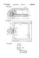
- FIG. 7is a top view of part of a shield box not covered by a lid like the lid 22 in FIG. 2.
- the electrical connection device in accordance with the inventionis of the type shown in FIG. 5.
- the base of the shield boxincludes the flange 15 to which the substrate 14 is screwed.
- the flange 15has a notch 70 at the location of the hole in the wall 12 providing access to the microstrip line on the substrate 14.
- This figureshows the construction of the base which is formed with partitions 23, etc for separating the microwave electronic functions.
- socketsincorporating an extension forming a ring insulated from the core.
- the bottom plate of the electronic circuitmay be of brass, copper or aluminum and the ring is preferably made from brass or aluminum.
- the length of the ringis in the order of 3.5 mm and its diameter is 2.2 or 4.15 mm, for example, depending on the socket used, in order to maintain the same characteristic impedance.
- FIG. 8is a cross-section view of another embodiment of a ring that can be used in the present invention.
- This ringhas a flat 80 so that it can be soldered to the bottom plate of the electronic circuit in the box. This further improves the grounding electrical contact.
Landscapes
- Engineering & Computer Science (AREA)
- Microelectronics & Electronic Packaging (AREA)
- Shielding Devices Or Components To Electric Or Magnetic Fields (AREA)
- Coupling Device And Connection With Printed Circuit (AREA)
Abstract
Description
1. Field of the Invention
The present invention relates to a system for making electrical contact between a coaxial plug or socket and a bottom plate of a microwave circuit enclosed in a shield box.
2. Description of the Prior Art
It is known for electronic circuits intended to operate at high frequencies to be implemented on a substrate, a PTFE-glass substrate, for example, in turn mounted on a conductive bottom plate, a brass bottom plate, for example. A circuit of this kind is then enclosed in an electromagnetic shield box and is electrically connected to surrounding devices by means of coaxial sockets fixed to the outside of the box, as shown in FIG. 1 which is a partial cross-section view of an electrical contact between a socket, which is an electrical connector, and an electronic circuit.
Asocket connector 10 is fixed byscrews 11 to aside wall 12 of an electromagnetic shielding box base. A microwave circuit comprising aconductive bottom plate 13 and asubstrate 14 is fixed inside the base which includes aflange 15 all around its perimeter and cooperates with alid 22 to form the box. Thebottom plate 13 with thesubstrate 14 on top of it is fixed by screws (not shown) to theflange 15, which thus acts as its support.
The core orcenter conductor 16 of thesocket 10 is partially enclosed by aninsulative sheath 17, a PTFE sheath, for example, and is inserted in ahole 18 through thewall 12. After thesocket 10 is screwed to thewall 12 the end of thecore 16 is soldered to thesubstrate 14.
The main drawback of this electrical connection system is that the grounding contact to be made between thebottom plate 13 and the body of thesocket 10 is made by way of theflange 15 and theinterface 19 between theflange 15 and thebottom plate 13. Theground path 20 shown by a dashed line is long and requires an excellent contact at theinterface 19.
Absorption of microwave energy is often observed when the grounding contact is established in this manner, especially at high frequencies, above a few GHz.
Another drawback of this connection system is thatindividual partitions 23 must be used if there is a requirement to separate microwave functions. Eachpartition 23 must then be screwed to thesubstrate 14 and provided on the edge facing thelid 22 with a microwave seal as there is necessarily some clearance between thelid 22 and the top of the partitions. The number of parts required to implement the microwave function is therefore large, as thepartitions 23 cannot be part of thelid 22 or of the base.
To overcome this latter drawback the microwave circuit comprising the substrate on the conductive bottom plate may be fixed as shown in FIG. 2.
The microwave circuit is screwed on from underneath by thescrews 25, in other words thesubstrate 14 bears against theflange 15. This makes it possible to reduce the number of mechanical parts used as the screening box comprises only abase 24 and thelid 22. Thepartitions 23 are an integral part of thebase 24.
However, in this type of assembly thebottom plate 13 is no longer in electrical contact with the box, as previously. This contact can only be established indirectly, for example by plated-through holes on either side of the access microstrip line of the microwave circuit; they are then ineffective at microwave frequencies because they are too far away from this access line.
An object of the present invention is to overcome these various drawbacks.
To be more precise, one object of the invention is to provide a system for making an electrical ground connection between a conductive bottom plate of a microwave circuit contained in an electromagnetic shield box and a connection socket fixed to the exterior of said box.
Another object of the invention is to be provide a socket with which an electrical ground connection of this kind may be made.
These objects, along with others that emerge later, are achieved by a system for making an electrical connection between an electronic circuit implemented on a substrate on an electrically conductive bottom plate fixed into an electromagnetic shield box and a coaxial socket fixed to an outside wall of said shield box, the core of said socket being inserted in a hole in said wall in order to be connected to said electronic circuit, said socket having a grounding surface facing said wall, in which system the grounding contact between said socket and said bottom plate is made by way of an electrically conductive ring coaxial with said core, insulated from said core and simultaneously in electrical contact with said grounding surface of said socket and said bottom plate when said socket is fixed to said wall of said box.
This ensures ground continuity between the socket and the bottom plate and the electronic circuit.
In an advantageous embodiment of the invention the ring cooperates with an electrically conductive spring washer coaxial with the core of the socket between the grounding surface and the ring.
The ring may have some elasticity. To this end it may be made from a synthetic material charged with metal.
In another embodiment, which may be complementary to the previous embodiment, the coaxial socket is screwed to the wall of the box and each screw cooperates with a spring washer.
The use of elastic components such as washers allows for machining tolerances and deformation of the materials employed, due to a change of temperature causing thermal expansion, for example.
In a preferred application the box has a flange to which the substrate is fixed, the flange having a notch at the location of the hole in the wall providing access to the electronic circuit for the microstrip line.
In this way it is possible to make high-performance grounding contacts for circuits contained in boxes as shown in FIG. 2.
The ring advantageously has a flat adapted to be soldered to the bottom plate of the electronic circuit. This further improves the ground contact.
The invention also concerns an electrical connection device including a coaxial socket having a core and a grounding surface, this device comprising an electrically conductive ring insulated from the core and coaxial therewith.
Other features and advantages of the invention emerge from the following description of various preferred embodiments of the invention given by way of non-limiting example and from the accompanying drawings.
FIG. 1 is a partial cross-section view of an electrical contact between a socket and an electronic circuit contained in a shield box.
FIG. 2 is a diagram showing an advantageous method of fixing an electronic circuit in a shield box.
FIG. 3 is a partial cross-section view of a first preferred embodiment of the invention.
FIG. 4 is a rear view of a socket used in the present invention.
FIG. 5 shows a second preferred embodiment of the invention.
FIG. 6 shows a third preferred embodiment of the invention.
FIG. 7 is a top view of a base fitted with the electrical connection device of the invention.
FIG. 8 is a cross-section view of another embodiment of a ring.
FIGS. 1 and 2 have already been described with reference to the prior art.
FIG. 3 shows a first preferred embodiment of the invention.
The electronic circuit implemented on thesubstrate 14 on the electricallyconductive bottom plate 13 is fixed as before into an electromagnetic shield box. A coaxial socket orelectrical connector 10 is fixed to thewall 12 of the shield box and the core orelectrical connector 16 of the socket is inserted in ahole 18 drilled in this wall in order to be connected to the electronic circuit. As shown in FIG. 4, which is a rear view of thesocket 10, the latter has a grounding surface near thecore 16 insulated by asheath 17. Thesheath 17 is made from PTFE, for example.
According to the invention, the grounding contact between thesocket 10 and thebottom plate 13 is made by way of an electricallyconductive ring 30 coaxial with and insulated from thecore 16 and simultaneously in electrical contact with the grounding surface of thesocket 10 and thebottom plate 13 when thesocket 10 is fixed to thewall 12. In FIG. 4 the position of thering 30 is shown by a dashed line.
In this way the grounding of thesocket 10 is extended through thewall 12 as far as thebottom plate 13. The grounding path is minimized and the electrical contact is optimized. Thesocket 10 is not necessarily in contact with thewall 12. As in the prior art thecore 16 may be soldered directly to a track on thesubstrate 14.
In the FIG. 3 embodiment thering 30 may be made from a material such as aluminum or brass and its length is calculated so that a good contact is established by deformation of the brass bottom plate.
It is equally possible to use a ring having some elasticity and to make it from a synthetic material charged with metal. The elasticity of the ring then provides an optimized ground contact.
In another embodiment shown in FIG. 5 thering 30 cooperates with aspring washer 50 coaxial with the core 16 between the grounding surface of thesocket 10 and thering 30. To ensure ground continuity thewasher 50 and thering 30 must be electrically conductive.
Thewasher 50 has an S-shape or cup-shape profile, for example. The elasticity of thewasher 50 means that it is possible to tolerate some location clearance between thebottom plate 13 and thewall 12, the distance between the electronic circuit and thewall 12 usually being in the order of 0.1 mm. With the various components correctly sized, after thescrews 11 are tightened thewasher 50 is almost entirely flattened between thesocket 10 and thering 30.
In a third embodiment shown in FIG. 6 eachscrew 11 fixing thesocket 10 to thewall 12 cooperates with aspring washer 60. The usual number of screws is four and the same effect is obtained as with the arrangement from FIG. 5.
Note that the arrangements of FIGS. 5 and 6 are particularly well suited to environments in which the components employed may change in size, for example expand. The use of elastic components allows for these changes and ensures an optimized grounding contact at all times.
FIG. 7 is a top view of part of a shield box not covered by a lid like thelid 22 in FIG. 2. In FIG. 7 the electrical connection device in accordance with the invention is of the type shown in FIG. 5.
The base of the shield box includes theflange 15 to which thesubstrate 14 is screwed. At the location of thesocket 10 theflange 15 has anotch 70 at the location of the hole in thewall 12 providing access to the microstrip line on thesubstrate 14. This figure shows the construction of the base which is formed withpartitions 23, etc for separating the microwave electronic functions.
It is also feasible to manufacture sockets incorporating an extension forming a ring insulated from the core.
With reference to the materials used, the bottom plate of the electronic circuit may be of brass, copper or aluminum and the ring is preferably made from brass or aluminum. The length of the ring is in the order of 3.5 mm and its diameter is 2.2 or 4.15 mm, for example, depending on the socket used, in order to maintain the same characteristic impedance.
FIG. 8 is a cross-section view of another embodiment of a ring that can be used in the present invention.
This ring has a flat 80 so that it can be soldered to the bottom plate of the electronic circuit in the box. This further improves the grounding electrical contact.
Claims (8)
1. A system for making an electrical connection between an electronic circuit implemented on a substrate on an electrically conductive bottom plate fixed into an electromagnetic shield box and a coaxial connector fixed to an outside wall of said shield box, the center conductor of said coaxial connector being inserted in a hole in said wall in order to be connected to said electronic circuit, said coaxial connector having a grounding surface facing said wall and an electrically conductive ring coaxial with said center conductor,
the grounding contact between said coaxial connector and said bottom plate is made axially of said electrically conductive ring, said electrically conductive ring being insulated from said center conductor and simultaneously in electrical contact axially with said grounding surface of said coaxial connector and said bottom plate with said coaxial connector being fixed to said wall of said box.
2. System according to claim 1 wherein said ring cooperates with an electrically conductive spring washer coaxial with said center conductor between said grounding surface and said ring.
3. A system according to claim 1, wherein said ring is elastic.
4. A system according to claim 3, wherein said elastic ring is made from a synthetic material charged with metal.
5. System according to claim 1 wherein said coaxial conductor is fixed to said wall of said box by screws and each screw cooperates with a spring washer.
6. System according to claim 1 wherein said box has a flange to which said substrate is fixed and having a notch at the location of said hole in said wall to provide access to a microstrip access line of said electronic circuit.
7. System according to claim 1 wherein said ring has a flat adapted to be soldered to said bottom plate.
8. A system as claimed in claim 1, wherein said electrically conductive ring includes first and second surfaces, each of which being transverse of an axis of said ring, said first and second surfaces simultaneously physically and electrically contacting said grounding surface and said bottom plate, respectively.
Applications Claiming Priority (2)
| Application Number | Priority Date | Filing Date | Title |
|---|---|---|---|
| FR9301709 | 1993-02-16 | ||
| FR9301709AFR2701603B1 (en) | 1993-02-16 | 1993-02-16 | Electrical ground connection system between a coaxial base and a soleplate of a microwave circuit and electrical connection device used in such a system. |
Publications (1)
| Publication Number | Publication Date |
|---|---|
| US5550521Atrue US5550521A (en) | 1996-08-27 |
Family
ID=9444090
Family Applications (1)
| Application Number | Title | Priority Date | Filing Date |
|---|---|---|---|
| US08/186,442Expired - LifetimeUS5550521A (en) | 1993-02-16 | 1994-01-25 | Electrical ground connection between a coaxial connector and a microwave circuit bottom plate |
Country Status (6)
| Country | Link |
|---|---|
| US (1) | US5550521A (en) |
| EP (1) | EP0612206B1 (en) |
| CA (1) | CA2115708C (en) |
| DE (1) | DE69400101T2 (en) |
| ES (1) | ES2084528T3 (en) |
| FR (1) | FR2701603B1 (en) |
Cited By (65)
| Publication number | Priority date | Publication date | Assignee | Title |
|---|---|---|---|---|
| US5971770A (en) | 1997-11-05 | 1999-10-26 | Labinal Components And Systems, Inc. | Coaxial connector with bellows spring portion or raised bump |
| US20040007834A1 (en)* | 2002-06-26 | 2004-01-15 | Friedrich Kohler | Device for guarding against electrostatic discharge and electromagnetic influences |
| US6692267B1 (en)* | 2001-08-23 | 2004-02-17 | Ciena Corporation | Printed circuit board testing module |
| US20040097105A1 (en)* | 2002-11-19 | 2004-05-20 | Harvey Kaylie | Mechanical case for housing electronic products with integrated connector |
| US20060152299A1 (en)* | 2005-01-12 | 2006-07-13 | Via Technologies, Inc. | Printed circuit board for connection with an external connector |
| US7566236B2 (en) | 2007-06-14 | 2009-07-28 | Thomas & Betts International, Inc. | Constant force coaxial cable connector |
| US7828595B2 (en) | 2004-11-24 | 2010-11-09 | John Mezzalingua Associates, Inc. | Connector having conductive member and method of use thereof |
| US7892005B2 (en) | 2009-05-19 | 2011-02-22 | John Mezzalingua Associates, Inc. | Click-tight coaxial cable continuity connector |
| US8029315B2 (en) | 2009-04-01 | 2011-10-04 | John Mezzalingua Associates, Inc. | Coaxial cable connector with improved physical and RF sealing |
| US8062063B2 (en) | 2008-09-30 | 2011-11-22 | Belden Inc. | Cable connector having a biasing element |
| US8075338B1 (en) | 2010-10-18 | 2011-12-13 | John Mezzalingua Associates, Inc. | Connector having a constant contact post |
| US8079860B1 (en) | 2010-07-22 | 2011-12-20 | John Mezzalingua Associates, Inc. | Cable connector having threaded locking collet and nut |
| US8113879B1 (en) | 2010-07-27 | 2012-02-14 | John Mezzalingua Associates, Inc. | One-piece compression connector body for coaxial cable connector |
| US8152551B2 (en) | 2010-07-22 | 2012-04-10 | John Mezzalingua Associates, Inc. | Port seizing cable connector nut and assembly |
| US8157589B2 (en) | 2004-11-24 | 2012-04-17 | John Mezzalingua Associates, Inc. | Connector having a conductively coated member and method of use thereof |
| US8167635B1 (en) | 2010-10-18 | 2012-05-01 | John Mezzalingua Associates, Inc. | Dielectric sealing member and method of use thereof |
| US8167636B1 (en) | 2010-10-15 | 2012-05-01 | John Mezzalingua Associates, Inc. | Connector having a continuity member |
| US8167646B1 (en) | 2010-10-18 | 2012-05-01 | John Mezzalingua Associates, Inc. | Connector having electrical continuity about an inner dielectric and method of use thereof |
| US8172612B2 (en) | 2005-01-25 | 2012-05-08 | Corning Gilbert Inc. | Electrical connector with grounding member |
| US8192237B2 (en) | 2009-05-22 | 2012-06-05 | John Mezzalingua Associates, Inc. | Coaxial cable connector having electrical continuity member |
| US8272893B2 (en) | 2009-11-16 | 2012-09-25 | Corning Gilbert Inc. | Integrally conductive and shielded coaxial cable connector |
| US8287310B2 (en) | 2009-02-24 | 2012-10-16 | Corning Gilbert Inc. | Coaxial connector with dual-grip nut |
| US8313345B2 (en) | 2009-04-02 | 2012-11-20 | John Mezzalingua Associates, Inc. | Coaxial cable continuity connector |
| US8323053B2 (en) | 2010-10-18 | 2012-12-04 | John Mezzalingua Associates, Inc. | Connector having a constant contact nut |
| US8337229B2 (en) | 2010-11-11 | 2012-12-25 | John Mezzalingua Associates, Inc. | Connector having a nut-body continuity element and method of use thereof |
| US8342879B2 (en) | 2011-03-25 | 2013-01-01 | John Mezzalingua Associates, Inc. | Coaxial cable connector |
| US8348697B2 (en) | 2011-04-22 | 2013-01-08 | John Mezzalingua Associates, Inc. | Coaxial cable connector having slotted post member |
| US8366481B2 (en) | 2011-03-30 | 2013-02-05 | John Mezzalingua Associates, Inc. | Continuity maintaining biasing member |
| US8388377B2 (en) | 2011-04-01 | 2013-03-05 | John Mezzalingua Associates, Inc. | Slide actuated coaxial cable connector |
| US8398421B2 (en) | 2011-02-01 | 2013-03-19 | John Mezzalingua Associates, Inc. | Connector having a dielectric seal and method of use thereof |
| US8414322B2 (en) | 2010-12-14 | 2013-04-09 | Ppc Broadband, Inc. | Push-on CATV port terminator |
| US8444445B2 (en) | 2009-05-22 | 2013-05-21 | Ppc Broadband, Inc. | Coaxial cable connector having electrical continuity member |
| US8465322B2 (en) | 2011-03-25 | 2013-06-18 | Ppc Broadband, Inc. | Coaxial cable connector |
| US8469739B2 (en) | 2011-02-08 | 2013-06-25 | Belden Inc. | Cable connector with biasing element |
| US8573996B2 (en) | 2009-05-22 | 2013-11-05 | Ppc Broadband, Inc. | Coaxial cable connector having electrical continuity member |
| US8591244B2 (en) | 2011-07-08 | 2013-11-26 | Ppc Broadband, Inc. | Cable connector |
| US8753147B2 (en) | 2011-06-10 | 2014-06-17 | Ppc Broadband, Inc. | Connector having a coupling member for locking onto a port and maintaining electrical continuity |
| US8888526B2 (en) | 2010-08-10 | 2014-11-18 | Corning Gilbert, Inc. | Coaxial cable connector with radio frequency interference and grounding shield |
| CN104241907A (en)* | 2014-09-24 | 2014-12-24 | 江苏省电力公司南京供电公司 | Grounding device |
| US9017101B2 (en) | 2011-03-30 | 2015-04-28 | Ppc Broadband, Inc. | Continuity maintaining biasing member |
| US9048599B2 (en) | 2013-10-28 | 2015-06-02 | Corning Gilbert Inc. | Coaxial cable connector having a gripping member with a notch and disposed inside a shell |
| US9071019B2 (en) | 2010-10-27 | 2015-06-30 | Corning Gilbert, Inc. | Push-on cable connector with a coupler and retention and release mechanism |
| US9130281B2 (en) | 2013-04-17 | 2015-09-08 | Ppc Broadband, Inc. | Post assembly for coaxial cable connectors |
| US9136654B2 (en) | 2012-01-05 | 2015-09-15 | Corning Gilbert, Inc. | Quick mount connector for a coaxial cable |
| US9147963B2 (en) | 2012-11-29 | 2015-09-29 | Corning Gilbert Inc. | Hardline coaxial connector with a locking ferrule |
| US9147955B2 (en) | 2011-11-02 | 2015-09-29 | Ppc Broadband, Inc. | Continuity providing port |
| US9153911B2 (en) | 2013-02-19 | 2015-10-06 | Corning Gilbert Inc. | Coaxial cable continuity connector |
| US9166348B2 (en) | 2010-04-13 | 2015-10-20 | Corning Gilbert Inc. | Coaxial connector with inhibited ingress and improved grounding |
| US9172154B2 (en) | 2013-03-15 | 2015-10-27 | Corning Gilbert Inc. | Coaxial cable connector with integral RFI protection |
| US9190744B2 (en) | 2011-09-14 | 2015-11-17 | Corning Optical Communications Rf Llc | Coaxial cable connector with radio frequency interference and grounding shield |
| US9203167B2 (en) | 2011-05-26 | 2015-12-01 | Ppc Broadband, Inc. | Coaxial cable connector with conductive seal |
| US9287659B2 (en) | 2012-10-16 | 2016-03-15 | Corning Optical Communications Rf Llc | Coaxial cable connector with integral RFI protection |
| US9407016B2 (en) | 2012-02-22 | 2016-08-02 | Corning Optical Communications Rf Llc | Coaxial cable connector with integral continuity contacting portion |
| US9525220B1 (en) | 2015-11-25 | 2016-12-20 | Corning Optical Communications LLC | Coaxial cable connector |
| US9548557B2 (en) | 2013-06-26 | 2017-01-17 | Corning Optical Communications LLC | Connector assemblies and methods of manufacture |
| US9548572B2 (en) | 2014-11-03 | 2017-01-17 | Corning Optical Communications LLC | Coaxial cable connector having a coupler and a post with a contacting portion and a shoulder |
| US9570845B2 (en) | 2009-05-22 | 2017-02-14 | Ppc Broadband, Inc. | Connector having a continuity member operable in a radial direction |
| US9590287B2 (en) | 2015-02-20 | 2017-03-07 | Corning Optical Communications Rf Llc | Surge protected coaxial termination |
| US9711917B2 (en) | 2011-05-26 | 2017-07-18 | Ppc Broadband, Inc. | Band spring continuity member for coaxial cable connector |
| US9762008B2 (en) | 2013-05-20 | 2017-09-12 | Corning Optical Communications Rf Llc | Coaxial cable connector with integral RFI protection |
| US9859631B2 (en) | 2011-09-15 | 2018-01-02 | Corning Optical Communications Rf Llc | Coaxial cable connector with integral radio frequency interference and grounding shield |
| US10033122B2 (en) | 2015-02-20 | 2018-07-24 | Corning Optical Communications Rf Llc | Cable or conduit connector with jacket retention feature |
| US10211547B2 (en) | 2015-09-03 | 2019-02-19 | Corning Optical Communications Rf Llc | Coaxial cable connector |
| US10290958B2 (en) | 2013-04-29 | 2019-05-14 | Corning Optical Communications Rf Llc | Coaxial cable connector with integral RFI protection and biasing ring |
| US12034264B2 (en) | 2021-03-31 | 2024-07-09 | Corning Optical Communications Rf Llc | Coaxial cable connector assemblies with outer conductor engagement features and methods for using the same |
Families Citing this family (2)
| Publication number | Priority date | Publication date | Assignee | Title |
|---|---|---|---|---|
| CN104989973B (en)* | 2015-06-25 | 2017-12-12 | 重庆驰山机械有限公司 | A kind of LED lamp tube |
| CN110416843B (en)* | 2019-07-12 | 2021-01-05 | 天津大学 | A Low PIM Coaxial Quick Release Adapter for Linearity and Power Capacity Testing |
Citations (8)
| Publication number | Priority date | Publication date | Assignee | Title |
|---|---|---|---|---|
| DE6931004U (en)* | 1969-08-05 | 1970-01-29 | Siemens Ag | SHIELDED ASSEMBLY FOR EQUIPMENT FOR ELECTRICAL COMMUNICATION AND MEASUREMENT TECHNOLOGY |
| EP0003133B1 (en)* | 1978-01-18 | 1981-04-29 | Société Anonyme dite SAFT | A sealed leading-through device for a single or double plastic partition wall by an electric connection, and its application to a battery of electrochemical generators |
| JPS5939101A (en)* | 1982-08-30 | 1984-03-03 | Fujitsu Ltd | Construction of coaxial-mic converter |
| JPS61174801A (en)* | 1985-01-29 | 1986-08-06 | Maspro Denkoh Corp | High frequency electronic equipment |
| US4656441A (en)* | 1983-08-01 | 1987-04-07 | Matsushita Electric Industrial Co., Ltd. | Coaxial line-to-microstrip line transition device |
| GB2181607A (en)* | 1985-10-04 | 1987-04-23 | Alps Electric Co Ltd | Shielding electronic devices |
| EP0429037A1 (en)* | 1989-11-20 | 1991-05-29 | Alcatel Radiotelephone | Shield for radio-frequency circuit |
| US5198786A (en)* | 1991-12-04 | 1993-03-30 | Raytheon Company | Waveguide transition circuit |
- 1993
- 1993-02-16FRFR9301709Apatent/FR2701603B1/ennot_activeExpired - Fee Related
- 1994
- 1994-01-25USUS08/186,442patent/US5550521A/ennot_activeExpired - Lifetime
- 1994-02-14DEDE69400101Tpatent/DE69400101T2/ennot_activeExpired - Lifetime
- 1994-02-14EPEP94400316Apatent/EP0612206B1/ennot_activeExpired - Lifetime
- 1994-02-14ESES94400316Tpatent/ES2084528T3/ennot_activeExpired - Lifetime
- 1994-02-15CACA002115708Apatent/CA2115708C/ennot_activeExpired - Fee Related
Patent Citations (8)
| Publication number | Priority date | Publication date | Assignee | Title |
|---|---|---|---|---|
| DE6931004U (en)* | 1969-08-05 | 1970-01-29 | Siemens Ag | SHIELDED ASSEMBLY FOR EQUIPMENT FOR ELECTRICAL COMMUNICATION AND MEASUREMENT TECHNOLOGY |
| EP0003133B1 (en)* | 1978-01-18 | 1981-04-29 | Société Anonyme dite SAFT | A sealed leading-through device for a single or double plastic partition wall by an electric connection, and its application to a battery of electrochemical generators |
| JPS5939101A (en)* | 1982-08-30 | 1984-03-03 | Fujitsu Ltd | Construction of coaxial-mic converter |
| US4656441A (en)* | 1983-08-01 | 1987-04-07 | Matsushita Electric Industrial Co., Ltd. | Coaxial line-to-microstrip line transition device |
| JPS61174801A (en)* | 1985-01-29 | 1986-08-06 | Maspro Denkoh Corp | High frequency electronic equipment |
| GB2181607A (en)* | 1985-10-04 | 1987-04-23 | Alps Electric Co Ltd | Shielding electronic devices |
| EP0429037A1 (en)* | 1989-11-20 | 1991-05-29 | Alcatel Radiotelephone | Shield for radio-frequency circuit |
| US5198786A (en)* | 1991-12-04 | 1993-03-30 | Raytheon Company | Waveguide transition circuit |
Non-Patent Citations (2)
| Title |
|---|
| Evans, Annular Ring Coaxial Termination, IBM Tech. Discl. Bulletin, vol. 16, No. 10, Mar. 1974. 333 260.* |
| Evans, Annular Ring Coaxial Termination, IBM Tech. Discl. Bulletin, vol. 16, No. 10, Mar. 1974. 333-260. |
Cited By (132)
| Publication number | Priority date | Publication date | Assignee | Title |
|---|---|---|---|---|
| US5971770A (en) | 1997-11-05 | 1999-10-26 | Labinal Components And Systems, Inc. | Coaxial connector with bellows spring portion or raised bump |
| US6692267B1 (en)* | 2001-08-23 | 2004-02-17 | Ciena Corporation | Printed circuit board testing module |
| US20040007834A1 (en)* | 2002-06-26 | 2004-01-15 | Friedrich Kohler | Device for guarding against electrostatic discharge and electromagnetic influences |
| US20040097105A1 (en)* | 2002-11-19 | 2004-05-20 | Harvey Kaylie | Mechanical case for housing electronic products with integrated connector |
| US6790049B2 (en)* | 2002-11-19 | 2004-09-14 | Scientific Components | Mechanical case for housing electronic products with integrated connector |
| US7833053B2 (en) | 2004-11-24 | 2010-11-16 | John Mezzalingua Associates, Inc. | Connector having conductive member and method of use thereof |
| US10038284B2 (en) | 2004-11-24 | 2018-07-31 | Ppc Broadband, Inc. | Connector having a grounding member |
| US7828595B2 (en) | 2004-11-24 | 2010-11-09 | John Mezzalingua Associates, Inc. | Connector having conductive member and method of use thereof |
| US8157589B2 (en) | 2004-11-24 | 2012-04-17 | John Mezzalingua Associates, Inc. | Connector having a conductively coated member and method of use thereof |
| US7845976B2 (en) | 2004-11-24 | 2010-12-07 | John Mezzalingua Associates, Inc. | Connector having conductive member and method of use thereof |
| US10446983B2 (en) | 2004-11-24 | 2019-10-15 | Ppc Broadband, Inc. | Connector having a grounding member |
| US7950958B2 (en) | 2004-11-24 | 2011-05-31 | John Messalingua Associates, Inc. | Connector having conductive member and method of use thereof |
| US10965063B2 (en) | 2004-11-24 | 2021-03-30 | Ppc Broadband, Inc. | Connector having a grounding member |
| US11984687B2 (en) | 2004-11-24 | 2024-05-14 | Ppc Broadband, Inc. | Connector having a grounding member |
| US12009619B2 (en) | 2004-11-24 | 2024-06-11 | Ppc Broadband, Inc. | Connector having a connector body conductive member |
| US9312611B2 (en) | 2004-11-24 | 2016-04-12 | Ppc Broadband, Inc. | Connector having a conductively coated member and method of use thereof |
| US20060152299A1 (en)* | 2005-01-12 | 2006-07-13 | Via Technologies, Inc. | Printed circuit board for connection with an external connector |
| US8172612B2 (en) | 2005-01-25 | 2012-05-08 | Corning Gilbert Inc. | Electrical connector with grounding member |
| US10756455B2 (en) | 2005-01-25 | 2020-08-25 | Corning Optical Communications Rf Llc | Electrical connector with grounding member |
| US8690603B2 (en) | 2005-01-25 | 2014-04-08 | Corning Gilbert Inc. | Electrical connector with grounding member |
| US7566236B2 (en) | 2007-06-14 | 2009-07-28 | Thomas & Betts International, Inc. | Constant force coaxial cable connector |
| USRE43832E1 (en) | 2007-06-14 | 2012-11-27 | Belden Inc. | Constant force coaxial cable connector |
| US8113875B2 (en) | 2008-09-30 | 2012-02-14 | Belden Inc. | Cable connector |
| US8062063B2 (en) | 2008-09-30 | 2011-11-22 | Belden Inc. | Cable connector having a biasing element |
| US8075337B2 (en) | 2008-09-30 | 2011-12-13 | Belden Inc. | Cable connector |
| US8506325B2 (en) | 2008-09-30 | 2013-08-13 | Belden Inc. | Cable connector having a biasing element |
| US8287310B2 (en) | 2009-02-24 | 2012-10-16 | Corning Gilbert Inc. | Coaxial connector with dual-grip nut |
| US8029315B2 (en) | 2009-04-01 | 2011-10-04 | John Mezzalingua Associates, Inc. | Coaxial cable connector with improved physical and RF sealing |
| US8506326B2 (en) | 2009-04-02 | 2013-08-13 | Ppc Broadband, Inc. | Coaxial cable continuity connector |
| US8313345B2 (en) | 2009-04-02 | 2012-11-20 | John Mezzalingua Associates, Inc. | Coaxial cable continuity connector |
| US7892005B2 (en) | 2009-05-19 | 2011-02-22 | John Mezzalingua Associates, Inc. | Click-tight coaxial cable continuity connector |
| US8801448B2 (en) | 2009-05-22 | 2014-08-12 | Ppc Broadband, Inc. | Coaxial cable connector having electrical continuity structure |
| US8573996B2 (en) | 2009-05-22 | 2013-11-05 | Ppc Broadband, Inc. | Coaxial cable connector having electrical continuity member |
| US8323060B2 (en) | 2009-05-22 | 2012-12-04 | John Mezzalingua Associates, Inc. | Coaxial cable connector having electrical continuity member |
| US12244108B2 (en) | 2009-05-22 | 2025-03-04 | Ppc Broadband, Inc. | Ground portion for maintaining a ground path in a coaxial cable connector |
| US8287320B2 (en) | 2009-05-22 | 2012-10-16 | John Mezzalingua Associates, Inc. | Coaxial cable connector having electrical continuity member |
| US9570845B2 (en) | 2009-05-22 | 2017-02-14 | Ppc Broadband, Inc. | Connector having a continuity member operable in a radial direction |
| US8192237B2 (en) | 2009-05-22 | 2012-06-05 | John Mezzalingua Associates, Inc. | Coaxial cable connector having electrical continuity member |
| US9419389B2 (en) | 2009-05-22 | 2016-08-16 | Ppc Broadband, Inc. | Coaxial cable connector having electrical continuity member |
| US10931068B2 (en) | 2009-05-22 | 2021-02-23 | Ppc Broadband, Inc. | Connector having a grounding member operable in a radial direction |
| US10862251B2 (en) | 2009-05-22 | 2020-12-08 | Ppc Broadband, Inc. | Coaxial cable connector having an electrical grounding portion |
| US9496661B2 (en) | 2009-05-22 | 2016-11-15 | Ppc Broadband, Inc. | Coaxial cable connector having electrical continuity member |
| US8444445B2 (en) | 2009-05-22 | 2013-05-21 | Ppc Broadband, Inc. | Coaxial cable connector having electrical continuity member |
| US8562366B2 (en) | 2009-05-22 | 2013-10-22 | Ppc Broadband, Inc. | Coaxial cable connector having electrical continuity member |
| US8313353B2 (en) | 2009-05-22 | 2012-11-20 | John Mezzalingua Associates, Inc. | Coaxial cable connector having electrical continuity member |
| US8597041B2 (en) | 2009-05-22 | 2013-12-03 | Ppc Broadband, Inc. | Coaxial cable connector having electrical continuity member |
| US8647136B2 (en) | 2009-05-22 | 2014-02-11 | Ppc Broadband, Inc. | Coaxial cable connector having electrical continuity member |
| US9660398B2 (en) | 2009-05-22 | 2017-05-23 | Ppc Broadband, Inc. | Coaxial cable connector having electrical continuity member |
| US8272893B2 (en) | 2009-11-16 | 2012-09-25 | Corning Gilbert Inc. | Integrally conductive and shielded coaxial cable connector |
| US10312629B2 (en) | 2010-04-13 | 2019-06-04 | Corning Optical Communications Rf Llc | Coaxial connector with inhibited ingress and improved grounding |
| US9166348B2 (en) | 2010-04-13 | 2015-10-20 | Corning Gilbert Inc. | Coaxial connector with inhibited ingress and improved grounding |
| US9905959B2 (en) | 2010-04-13 | 2018-02-27 | Corning Optical Communication RF LLC | Coaxial connector with inhibited ingress and improved grounding |
| US8079860B1 (en) | 2010-07-22 | 2011-12-20 | John Mezzalingua Associates, Inc. | Cable connector having threaded locking collet and nut |
| US8152551B2 (en) | 2010-07-22 | 2012-04-10 | John Mezzalingua Associates, Inc. | Port seizing cable connector nut and assembly |
| US8113879B1 (en) | 2010-07-27 | 2012-02-14 | John Mezzalingua Associates, Inc. | One-piece compression connector body for coaxial cable connector |
| US8888526B2 (en) | 2010-08-10 | 2014-11-18 | Corning Gilbert, Inc. | Coaxial cable connector with radio frequency interference and grounding shield |
| US8167636B1 (en) | 2010-10-15 | 2012-05-01 | John Mezzalingua Associates, Inc. | Connector having a continuity member |
| US8167646B1 (en) | 2010-10-18 | 2012-05-01 | John Mezzalingua Associates, Inc. | Connector having electrical continuity about an inner dielectric and method of use thereof |
| US8167635B1 (en) | 2010-10-18 | 2012-05-01 | John Mezzalingua Associates, Inc. | Dielectric sealing member and method of use thereof |
| US8323053B2 (en) | 2010-10-18 | 2012-12-04 | John Mezzalingua Associates, Inc. | Connector having a constant contact nut |
| US8382517B2 (en) | 2010-10-18 | 2013-02-26 | John Mezzalingua Associates, Inc. | Dielectric sealing member and method of use thereof |
| US8075338B1 (en) | 2010-10-18 | 2011-12-13 | John Mezzalingua Associates, Inc. | Connector having a constant contact post |
| US9071019B2 (en) | 2010-10-27 | 2015-06-30 | Corning Gilbert, Inc. | Push-on cable connector with a coupler and retention and release mechanism |
| US8920192B2 (en) | 2010-11-11 | 2014-12-30 | Ppc Broadband, Inc. | Connector having a coupler-body continuity member |
| US8915754B2 (en) | 2010-11-11 | 2014-12-23 | Ppc Broadband, Inc. | Connector having a coupler-body continuity member |
| US8337229B2 (en) | 2010-11-11 | 2012-12-25 | John Mezzalingua Associates, Inc. | Connector having a nut-body continuity element and method of use thereof |
| US10686264B2 (en) | 2010-11-11 | 2020-06-16 | Ppc Broadband, Inc. | Coaxial cable connector having a grounding bridge portion |
| US8920182B2 (en) | 2010-11-11 | 2014-12-30 | Ppc Broadband, Inc. | Connector having a coupler-body continuity member |
| US8858251B2 (en) | 2010-11-11 | 2014-10-14 | Ppc Broadband, Inc. | Connector having a coupler-body continuity member |
| US8529279B2 (en) | 2010-11-11 | 2013-09-10 | Ppc Broadband, Inc. | Connector having a nut-body continuity element and method of use thereof |
| US8550835B2 (en) | 2010-11-11 | 2013-10-08 | Ppc Broadband, Inc. | Connector having a nut-body continuity element and method of use thereof |
| US8414322B2 (en) | 2010-12-14 | 2013-04-09 | Ppc Broadband, Inc. | Push-on CATV port terminator |
| US8398421B2 (en) | 2011-02-01 | 2013-03-19 | John Mezzalingua Associates, Inc. | Connector having a dielectric seal and method of use thereof |
| US8469739B2 (en) | 2011-02-08 | 2013-06-25 | Belden Inc. | Cable connector with biasing element |
| US8342879B2 (en) | 2011-03-25 | 2013-01-01 | John Mezzalingua Associates, Inc. | Coaxial cable connector |
| US8465322B2 (en) | 2011-03-25 | 2013-06-18 | Ppc Broadband, Inc. | Coaxial cable connector |
| US9153917B2 (en) | 2011-03-25 | 2015-10-06 | Ppc Broadband, Inc. | Coaxial cable connector |
| US11811184B2 (en) | 2011-03-30 | 2023-11-07 | Ppc Broadband, Inc. | Connector producing a biasing force |
| US8475205B2 (en) | 2011-03-30 | 2013-07-02 | Ppc Broadband, Inc. | Continuity maintaining biasing member |
| US9595776B2 (en) | 2011-03-30 | 2017-03-14 | Ppc Broadband, Inc. | Connector producing a biasing force |
| US8366481B2 (en) | 2011-03-30 | 2013-02-05 | John Mezzalingua Associates, Inc. | Continuity maintaining biasing member |
| US10186790B2 (en) | 2011-03-30 | 2019-01-22 | Ppc Broadband, Inc. | Connector producing a biasing force |
| US8469740B2 (en) | 2011-03-30 | 2013-06-25 | Ppc Broadband, Inc. | Continuity maintaining biasing member |
| US8480431B2 (en) | 2011-03-30 | 2013-07-09 | Ppc Broadband, Inc. | Continuity maintaining biasing member |
| US10559898B2 (en) | 2011-03-30 | 2020-02-11 | Ppc Broadband, Inc. | Connector producing a biasing force |
| US9608345B2 (en) | 2011-03-30 | 2017-03-28 | Ppc Broadband, Inc. | Continuity maintaining biasing member |
| US9017101B2 (en) | 2011-03-30 | 2015-04-28 | Ppc Broadband, Inc. | Continuity maintaining biasing member |
| US8485845B2 (en) | 2011-03-30 | 2013-07-16 | Ppc Broadband, Inc. | Continuity maintaining biasing member |
| US8480430B2 (en) | 2011-03-30 | 2013-07-09 | Ppc Broadband, Inc. | Continuity maintaining biasing member |
| US9660360B2 (en) | 2011-03-30 | 2017-05-23 | Ppc Broadband, Inc. | Connector producing a biasing force |
| US8388377B2 (en) | 2011-04-01 | 2013-03-05 | John Mezzalingua Associates, Inc. | Slide actuated coaxial cable connector |
| US8348697B2 (en) | 2011-04-22 | 2013-01-08 | John Mezzalingua Associates, Inc. | Coaxial cable connector having slotted post member |
| US9711917B2 (en) | 2011-05-26 | 2017-07-18 | Ppc Broadband, Inc. | Band spring continuity member for coaxial cable connector |
| US9203167B2 (en) | 2011-05-26 | 2015-12-01 | Ppc Broadband, Inc. | Coaxial cable connector with conductive seal |
| US11283226B2 (en) | 2011-05-26 | 2022-03-22 | Ppc Broadband, Inc. | Grounding member for coaxial cable connector |
| US10707629B2 (en) | 2011-05-26 | 2020-07-07 | Ppc Broadband, Inc. | Grounding member for coaxial cable connector |
| US8758050B2 (en) | 2011-06-10 | 2014-06-24 | Hiscock & Barclay LLP | Connector having a coupling member for locking onto a port and maintaining electrical continuity |
| US8753147B2 (en) | 2011-06-10 | 2014-06-17 | Ppc Broadband, Inc. | Connector having a coupling member for locking onto a port and maintaining electrical continuity |
| US8591244B2 (en) | 2011-07-08 | 2013-11-26 | Ppc Broadband, Inc. | Cable connector |
| US9190744B2 (en) | 2011-09-14 | 2015-11-17 | Corning Optical Communications Rf Llc | Coaxial cable connector with radio frequency interference and grounding shield |
| US9859631B2 (en) | 2011-09-15 | 2018-01-02 | Corning Optical Communications Rf Llc | Coaxial cable connector with integral radio frequency interference and grounding shield |
| US10116099B2 (en) | 2011-11-02 | 2018-10-30 | Ppc Broadband, Inc. | Devices for biasingly maintaining a port ground path |
| US9537232B2 (en) | 2011-11-02 | 2017-01-03 | Ppc Broadband, Inc. | Continuity providing port |
| US11233362B2 (en) | 2011-11-02 | 2022-01-25 | Ppc Broadband, Inc. | Devices for biasingly maintaining a port ground path |
| US10700475B2 (en) | 2011-11-02 | 2020-06-30 | Ppc Broadband, Inc. | Devices for biasingly maintaining a port ground path |
| US9147955B2 (en) | 2011-11-02 | 2015-09-29 | Ppc Broadband, Inc. | Continuity providing port |
| US9768565B2 (en) | 2012-01-05 | 2017-09-19 | Corning Optical Communications Rf Llc | Quick mount connector for a coaxial cable |
| US9136654B2 (en) | 2012-01-05 | 2015-09-15 | Corning Gilbert, Inc. | Quick mount connector for a coaxial cable |
| US9484645B2 (en) | 2012-01-05 | 2016-11-01 | Corning Optical Communications Rf Llc | Quick mount connector for a coaxial cable |
| US9407016B2 (en) | 2012-02-22 | 2016-08-02 | Corning Optical Communications Rf Llc | Coaxial cable connector with integral continuity contacting portion |
| US9722363B2 (en) | 2012-10-16 | 2017-08-01 | Corning Optical Communications Rf Llc | Coaxial cable connector with integral RFI protection |
| US9287659B2 (en) | 2012-10-16 | 2016-03-15 | Corning Optical Communications Rf Llc | Coaxial cable connector with integral RFI protection |
| US9912105B2 (en) | 2012-10-16 | 2018-03-06 | Corning Optical Communications Rf Llc | Coaxial cable connector with integral RFI protection |
| US10236636B2 (en) | 2012-10-16 | 2019-03-19 | Corning Optical Communications Rf Llc | Coaxial cable connector with integral RFI protection |
| US9147963B2 (en) | 2012-11-29 | 2015-09-29 | Corning Gilbert Inc. | Hardline coaxial connector with a locking ferrule |
| US9153911B2 (en) | 2013-02-19 | 2015-10-06 | Corning Gilbert Inc. | Coaxial cable continuity connector |
| US9172154B2 (en) | 2013-03-15 | 2015-10-27 | Corning Gilbert Inc. | Coaxial cable connector with integral RFI protection |
| US9130281B2 (en) | 2013-04-17 | 2015-09-08 | Ppc Broadband, Inc. | Post assembly for coaxial cable connectors |
| US10290958B2 (en) | 2013-04-29 | 2019-05-14 | Corning Optical Communications Rf Llc | Coaxial cable connector with integral RFI protection and biasing ring |
| US9762008B2 (en) | 2013-05-20 | 2017-09-12 | Corning Optical Communications Rf Llc | Coaxial cable connector with integral RFI protection |
| US10396508B2 (en) | 2013-05-20 | 2019-08-27 | Corning Optical Communications Rf Llc | Coaxial cable connector with integral RFI protection |
| US9548557B2 (en) | 2013-06-26 | 2017-01-17 | Corning Optical Communications LLC | Connector assemblies and methods of manufacture |
| US9048599B2 (en) | 2013-10-28 | 2015-06-02 | Corning Gilbert Inc. | Coaxial cable connector having a gripping member with a notch and disposed inside a shell |
| CN104241907A (en)* | 2014-09-24 | 2014-12-24 | 江苏省电力公司南京供电公司 | Grounding device |
| US9991651B2 (en) | 2014-11-03 | 2018-06-05 | Corning Optical Communications Rf Llc | Coaxial cable connector with post including radially expanding tabs |
| US9548572B2 (en) | 2014-11-03 | 2017-01-17 | Corning Optical Communications LLC | Coaxial cable connector having a coupler and a post with a contacting portion and a shoulder |
| US9590287B2 (en) | 2015-02-20 | 2017-03-07 | Corning Optical Communications Rf Llc | Surge protected coaxial termination |
| US10033122B2 (en) | 2015-02-20 | 2018-07-24 | Corning Optical Communications Rf Llc | Cable or conduit connector with jacket retention feature |
| US10211547B2 (en) | 2015-09-03 | 2019-02-19 | Corning Optical Communications Rf Llc | Coaxial cable connector |
| US9882320B2 (en) | 2015-11-25 | 2018-01-30 | Corning Optical Communications Rf Llc | Coaxial cable connector |
| US9525220B1 (en) | 2015-11-25 | 2016-12-20 | Corning Optical Communications LLC | Coaxial cable connector |
| US12034264B2 (en) | 2021-03-31 | 2024-07-09 | Corning Optical Communications Rf Llc | Coaxial cable connector assemblies with outer conductor engagement features and methods for using the same |
Also Published As
| Publication number | Publication date |
|---|---|
| EP0612206B1 (en) | 1996-03-20 |
| CA2115708C (en) | 2000-10-17 |
| CA2115708A1 (en) | 1994-08-17 |
| FR2701603B1 (en) | 1995-04-14 |
| FR2701603A1 (en) | 1994-08-19 |
| ES2084528T3 (en) | 1996-05-01 |
| DE69400101D1 (en) | 1996-04-25 |
| EP0612206A1 (en) | 1994-08-24 |
| DE69400101T2 (en) | 1996-08-22 |
Similar Documents
| Publication | Publication Date | Title |
|---|---|---|
| US5550521A (en) | Electrical ground connection between a coaxial connector and a microwave circuit bottom plate | |
| US4567317A (en) | EMI/RFI Protected enclosure | |
| JP2546590Y2 (en) | Filter connector and shield plate for filter connector | |
| US6290538B1 (en) | RJ type coaxial cable connector with visual indicator | |
| US3757272A (en) | Strip transmission line coupler | |
| US3783321A (en) | Coaxial connector | |
| US4656441A (en) | Coaxial line-to-microstrip line transition device | |
| US7010858B2 (en) | Method of fabricating a shielded zero insertion force socket | |
| US6152743A (en) | Coaxial connectors with integral electronic components | |
| KR970705200A (en) | Assembly of Shielded Connectors and a Board Having Plated Holes | |
| JPH06314580A (en) | Coaxial connection for two boards connection | |
| US4768004A (en) | Electrical circuit interconnect system | |
| US6344978B1 (en) | Shield case including a material giving a large transmission loss to a radio frequency signal | |
| US4707039A (en) | Coaxial connector for controlled impedance transmission lines | |
| US4825015A (en) | Electromagnetic shielding arrangement | |
| CA2105043A1 (en) | Electronic Components and Systems Using Coaxial Cable Technology | |
| US3594687A (en) | Connector for coupling a coaxial cable to a printed circuit board or the like | |
| US6707675B1 (en) | EMI containment device and method | |
| JPH03112204A (en) | Microwave detector | |
| KR101285675B1 (en) | Housing structure for electronic device, as well as method for creating such a housing structure | |
| US4541683A (en) | Device for mounting an electrical connector to a conductive panel | |
| US4859977A (en) | Insulator device for power transformer | |
| US4801269A (en) | Coaxial connector for use with printed circuit board edge connector | |
| US5081434A (en) | Filter connector | |
| US20020054485A1 (en) | Apparatus for shielding |
Legal Events
| Date | Code | Title | Description |
|---|---|---|---|
| AS | Assignment | Owner name:ALCATEL TELSPACE, FRANCE Free format text:ASSIGNMENT OF ASSIGNORS INTEREST;ASSIGNORS:BERNAUD, MAURICE;MAQUET, FREDDY;REEL/FRAME:006872/0367 Effective date:19940110 | |
| FEPP | Fee payment procedure | Free format text:PAYOR NUMBER ASSIGNED (ORIGINAL EVENT CODE: ASPN); ENTITY STATUS OF PATENT OWNER: LARGE ENTITY | |
| STCF | Information on status: patent grant | Free format text:PATENTED CASE | |
| FPAY | Fee payment | Year of fee payment:4 | |
| FPAY | Fee payment | Year of fee payment:8 | |
| FPAY | Fee payment | Year of fee payment:12 |