US5549702A - Flexible orthopaedic stem apparatus - Google Patents
Flexible orthopaedic stem apparatusDownload PDFInfo
- Publication number
- US5549702A US5549702AUS08/328,363US32836394AUS5549702AUS 5549702 AUS5549702 AUS 5549702AUS 32836394 AUS32836394 AUS 32836394AUS 5549702 AUS5549702 AUS 5549702A
- Authority
- US
- United States
- Prior art keywords
- stem
- prosthesis
- proximal
- bore
- helical groove
- Prior art date
- Legal status (The legal status is an assumption and is not a legal conclusion. Google has not performed a legal analysis and makes no representation as to the accuracy of the status listed.)
- Expired - Lifetime
Links
- 238000002513implantationMethods0.000claimsabstractdescription6
- 210000000988bone and boneAnatomy0.000claimsdescription13
- 239000007943implantSubstances0.000description34
- 210000000689upper legAnatomy0.000description16
- 210000001624hipAnatomy0.000description13
- 239000000463materialSubstances0.000description8
- 229910052751metalInorganic materials0.000description7
- 239000002184metalSubstances0.000description7
- 239000002131composite materialSubstances0.000description6
- 239000007787solidSubstances0.000description5
- 210000000588acetabulumAnatomy0.000description4
- 230000007423decreaseEffects0.000description4
- 239000010432diamondSubstances0.000description4
- 230000006835compressionEffects0.000description3
- 238000007906compressionMethods0.000description3
- 238000013461designMethods0.000description3
- 239000000835fiberSubstances0.000description3
- 210000004394hip jointAnatomy0.000description3
- 210000003127kneeAnatomy0.000description3
- RTAQQCXQSZGOHL-UHFFFAOYSA-NTitaniumChemical compound[Ti]RTAQQCXQSZGOHL-UHFFFAOYSA-N0.000description2
- 230000008901benefitEffects0.000description2
- 238000009826distributionMethods0.000description2
- 239000013536elastomeric materialSubstances0.000description2
- 230000013011matingEffects0.000description2
- 210000003049pelvic boneAnatomy0.000description2
- 239000010936titaniumSubstances0.000description2
- 229910052719titaniumInorganic materials0.000description2
- 238000012546transferMethods0.000description2
- 230000007704transitionEffects0.000description2
- 239000002023woodSubstances0.000description2
- OKTJSMMVPCPJKN-UHFFFAOYSA-NCarbonChemical compound[C]OKTJSMMVPCPJKN-UHFFFAOYSA-N0.000description1
- 229910000531Co alloyInorganic materials0.000description1
- 206010020880HypertrophyDiseases0.000description1
- 229910001069Ti alloyInorganic materials0.000description1
- 241000469816VarusSpecies0.000description1
- 230000003044adaptive effectEffects0.000description1
- 238000005452bendingMethods0.000description1
- 229910052799carbonInorganic materials0.000description1
- 238000010276constructionMethods0.000description1
- 230000001054cortical effectEffects0.000description1
- 230000000694effectsEffects0.000description1
- 229920001971elastomerPolymers0.000description1
- 239000000806elastomerSubstances0.000description1
- 210000001513elbowAnatomy0.000description1
- 230000036433growing bodyEffects0.000description1
- 210000002758humerusAnatomy0.000description1
- 230000006872improvementEffects0.000description1
- 238000010348incorporationMethods0.000description1
- 238000003780insertionMethods0.000description1
- 230000037431insertionEffects0.000description1
- 230000007774longtermEffects0.000description1
- 238000013508migrationMethods0.000description1
- 230000005012migrationEffects0.000description1
- 238000012986modificationMethods0.000description1
- 230000004048modificationEffects0.000description1
- 210000004197pelvisAnatomy0.000description1
- 230000002980postoperative effectEffects0.000description1
- 210000002832shoulderAnatomy0.000description1
- 210000002303tibiaAnatomy0.000description1
- 210000000707wristAnatomy0.000description1
Images


Classifications
- A—HUMAN NECESSITIES
- A61—MEDICAL OR VETERINARY SCIENCE; HYGIENE
- A61F—FILTERS IMPLANTABLE INTO BLOOD VESSELS; PROSTHESES; DEVICES PROVIDING PATENCY TO, OR PREVENTING COLLAPSING OF, TUBULAR STRUCTURES OF THE BODY, e.g. STENTS; ORTHOPAEDIC, NURSING OR CONTRACEPTIVE DEVICES; FOMENTATION; TREATMENT OR PROTECTION OF EYES OR EARS; BANDAGES, DRESSINGS OR ABSORBENT PADS; FIRST-AID KITS
- A61F2/00—Filters implantable into blood vessels; Prostheses, i.e. artificial substitutes or replacements for parts of the body; Appliances for connecting them with the body; Devices providing patency to, or preventing collapsing of, tubular structures of the body, e.g. stents
- A61F2/02—Prostheses implantable into the body
- A61F2/30—Joints
- A61F2/32—Joints for the hip
- A61F2/36—Femoral heads ; Femoral endoprostheses
- A61F2/3662—Femoral shafts
- A61F2/3676—Distal or diaphyseal parts of shafts
- A—HUMAN NECESSITIES
- A61—MEDICAL OR VETERINARY SCIENCE; HYGIENE
- A61F—FILTERS IMPLANTABLE INTO BLOOD VESSELS; PROSTHESES; DEVICES PROVIDING PATENCY TO, OR PREVENTING COLLAPSING OF, TUBULAR STRUCTURES OF THE BODY, e.g. STENTS; ORTHOPAEDIC, NURSING OR CONTRACEPTIVE DEVICES; FOMENTATION; TREATMENT OR PROTECTION OF EYES OR EARS; BANDAGES, DRESSINGS OR ABSORBENT PADS; FIRST-AID KITS
- A61F2/00—Filters implantable into blood vessels; Prostheses, i.e. artificial substitutes or replacements for parts of the body; Appliances for connecting them with the body; Devices providing patency to, or preventing collapsing of, tubular structures of the body, e.g. stents
- A61F2/02—Prostheses implantable into the body
- A61F2/30—Joints
- A61F2/32—Joints for the hip
- A61F2/36—Femoral heads ; Femoral endoprostheses
- A—HUMAN NECESSITIES
- A61—MEDICAL OR VETERINARY SCIENCE; HYGIENE
- A61F—FILTERS IMPLANTABLE INTO BLOOD VESSELS; PROSTHESES; DEVICES PROVIDING PATENCY TO, OR PREVENTING COLLAPSING OF, TUBULAR STRUCTURES OF THE BODY, e.g. STENTS; ORTHOPAEDIC, NURSING OR CONTRACEPTIVE DEVICES; FOMENTATION; TREATMENT OR PROTECTION OF EYES OR EARS; BANDAGES, DRESSINGS OR ABSORBENT PADS; FIRST-AID KITS
- A61F2/00—Filters implantable into blood vessels; Prostheses, i.e. artificial substitutes or replacements for parts of the body; Appliances for connecting them with the body; Devices providing patency to, or preventing collapsing of, tubular structures of the body, e.g. stents
- A61F2/02—Prostheses implantable into the body
- A61F2/30—Joints
- A61F2/46—Special tools for implanting artificial joints
- A61F2/4603—Special tools for implanting artificial joints for insertion or extraction of endoprosthetic joints or of accessories thereof
- A61F2/4607—Special tools for implanting artificial joints for insertion or extraction of endoprosthetic joints or of accessories thereof of hip femoral endoprostheses
- A—HUMAN NECESSITIES
- A61—MEDICAL OR VETERINARY SCIENCE; HYGIENE
- A61F—FILTERS IMPLANTABLE INTO BLOOD VESSELS; PROSTHESES; DEVICES PROVIDING PATENCY TO, OR PREVENTING COLLAPSING OF, TUBULAR STRUCTURES OF THE BODY, e.g. STENTS; ORTHOPAEDIC, NURSING OR CONTRACEPTIVE DEVICES; FOMENTATION; TREATMENT OR PROTECTION OF EYES OR EARS; BANDAGES, DRESSINGS OR ABSORBENT PADS; FIRST-AID KITS
- A61F2/00—Filters implantable into blood vessels; Prostheses, i.e. artificial substitutes or replacements for parts of the body; Appliances for connecting them with the body; Devices providing patency to, or preventing collapsing of, tubular structures of the body, e.g. stents
- A61F2/02—Prostheses implantable into the body
- A61F2/30—Joints
- A61F2002/30001—Additional features of subject-matter classified in A61F2/28, A61F2/30 and subgroups thereof
- A61F2002/30003—Material related properties of the prosthesis or of a coating on the prosthesis
- A61F2002/30004—Material related properties of the prosthesis or of a coating on the prosthesis the prosthesis being made from materials having different values of a given property at different locations within the same prosthesis
- A61F2002/30014—Material related properties of the prosthesis or of a coating on the prosthesis the prosthesis being made from materials having different values of a given property at different locations within the same prosthesis differing in elasticity, stiffness or compressibility
- A—HUMAN NECESSITIES
- A61—MEDICAL OR VETERINARY SCIENCE; HYGIENE
- A61F—FILTERS IMPLANTABLE INTO BLOOD VESSELS; PROSTHESES; DEVICES PROVIDING PATENCY TO, OR PREVENTING COLLAPSING OF, TUBULAR STRUCTURES OF THE BODY, e.g. STENTS; ORTHOPAEDIC, NURSING OR CONTRACEPTIVE DEVICES; FOMENTATION; TREATMENT OR PROTECTION OF EYES OR EARS; BANDAGES, DRESSINGS OR ABSORBENT PADS; FIRST-AID KITS
- A61F2/00—Filters implantable into blood vessels; Prostheses, i.e. artificial substitutes or replacements for parts of the body; Appliances for connecting them with the body; Devices providing patency to, or preventing collapsing of, tubular structures of the body, e.g. stents
- A61F2/02—Prostheses implantable into the body
- A61F2/30—Joints
- A61F2002/30001—Additional features of subject-matter classified in A61F2/28, A61F2/30 and subgroups thereof
- A61F2002/30108—Shapes
- A61F2002/3011—Cross-sections or two-dimensional shapes
- A61F2002/30112—Rounded shapes, e.g. with rounded corners
- A61F2002/30131—Rounded shapes, e.g. with rounded corners horseshoe- or crescent- or C-shaped or U-shaped
- A—HUMAN NECESSITIES
- A61—MEDICAL OR VETERINARY SCIENCE; HYGIENE
- A61F—FILTERS IMPLANTABLE INTO BLOOD VESSELS; PROSTHESES; DEVICES PROVIDING PATENCY TO, OR PREVENTING COLLAPSING OF, TUBULAR STRUCTURES OF THE BODY, e.g. STENTS; ORTHOPAEDIC, NURSING OR CONTRACEPTIVE DEVICES; FOMENTATION; TREATMENT OR PROTECTION OF EYES OR EARS; BANDAGES, DRESSINGS OR ABSORBENT PADS; FIRST-AID KITS
- A61F2/00—Filters implantable into blood vessels; Prostheses, i.e. artificial substitutes or replacements for parts of the body; Appliances for connecting them with the body; Devices providing patency to, or preventing collapsing of, tubular structures of the body, e.g. stents
- A61F2/02—Prostheses implantable into the body
- A61F2/30—Joints
- A61F2002/30001—Additional features of subject-matter classified in A61F2/28, A61F2/30 and subgroups thereof
- A61F2002/30108—Shapes
- A61F2002/30199—Three-dimensional shapes
- A61F2002/30224—Three-dimensional shapes cylindrical
- A61F2002/30235—Three-dimensional shapes cylindrical tubular, e.g. sleeves
- A—HUMAN NECESSITIES
- A61—MEDICAL OR VETERINARY SCIENCE; HYGIENE
- A61F—FILTERS IMPLANTABLE INTO BLOOD VESSELS; PROSTHESES; DEVICES PROVIDING PATENCY TO, OR PREVENTING COLLAPSING OF, TUBULAR STRUCTURES OF THE BODY, e.g. STENTS; ORTHOPAEDIC, NURSING OR CONTRACEPTIVE DEVICES; FOMENTATION; TREATMENT OR PROTECTION OF EYES OR EARS; BANDAGES, DRESSINGS OR ABSORBENT PADS; FIRST-AID KITS
- A61F2/00—Filters implantable into blood vessels; Prostheses, i.e. artificial substitutes or replacements for parts of the body; Appliances for connecting them with the body; Devices providing patency to, or preventing collapsing of, tubular structures of the body, e.g. stents
- A61F2/02—Prostheses implantable into the body
- A61F2/30—Joints
- A61F2002/30001—Additional features of subject-matter classified in A61F2/28, A61F2/30 and subgroups thereof
- A61F2002/30108—Shapes
- A61F2002/30199—Three-dimensional shapes
- A61F2002/30289—Three-dimensional shapes helically-coiled
- A—HUMAN NECESSITIES
- A61—MEDICAL OR VETERINARY SCIENCE; HYGIENE
- A61F—FILTERS IMPLANTABLE INTO BLOOD VESSELS; PROSTHESES; DEVICES PROVIDING PATENCY TO, OR PREVENTING COLLAPSING OF, TUBULAR STRUCTURES OF THE BODY, e.g. STENTS; ORTHOPAEDIC, NURSING OR CONTRACEPTIVE DEVICES; FOMENTATION; TREATMENT OR PROTECTION OF EYES OR EARS; BANDAGES, DRESSINGS OR ABSORBENT PADS; FIRST-AID KITS
- A61F2/00—Filters implantable into blood vessels; Prostheses, i.e. artificial substitutes or replacements for parts of the body; Appliances for connecting them with the body; Devices providing patency to, or preventing collapsing of, tubular structures of the body, e.g. stents
- A61F2/02—Prostheses implantable into the body
- A61F2/30—Joints
- A61F2002/30001—Additional features of subject-matter classified in A61F2/28, A61F2/30 and subgroups thereof
- A61F2002/30316—The prosthesis having different structural features at different locations within the same prosthesis; Connections between prosthetic parts; Special structural features of bone or joint prostheses not otherwise provided for
- A61F2002/30317—The prosthesis having different structural features at different locations within the same prosthesis
- A61F2002/30319—The prosthesis having different structural features at different locations within the same prosthesis differing in moment of inertia
- A—HUMAN NECESSITIES
- A61—MEDICAL OR VETERINARY SCIENCE; HYGIENE
- A61F—FILTERS IMPLANTABLE INTO BLOOD VESSELS; PROSTHESES; DEVICES PROVIDING PATENCY TO, OR PREVENTING COLLAPSING OF, TUBULAR STRUCTURES OF THE BODY, e.g. STENTS; ORTHOPAEDIC, NURSING OR CONTRACEPTIVE DEVICES; FOMENTATION; TREATMENT OR PROTECTION OF EYES OR EARS; BANDAGES, DRESSINGS OR ABSORBENT PADS; FIRST-AID KITS
- A61F2/00—Filters implantable into blood vessels; Prostheses, i.e. artificial substitutes or replacements for parts of the body; Appliances for connecting them with the body; Devices providing patency to, or preventing collapsing of, tubular structures of the body, e.g. stents
- A61F2/02—Prostheses implantable into the body
- A61F2/30—Joints
- A61F2002/30001—Additional features of subject-matter classified in A61F2/28, A61F2/30 and subgroups thereof
- A61F2002/30316—The prosthesis having different structural features at different locations within the same prosthesis; Connections between prosthetic parts; Special structural features of bone or joint prostheses not otherwise provided for
- A61F2002/30317—The prosthesis having different structural features at different locations within the same prosthesis
- A61F2002/30324—The prosthesis having different structural features at different locations within the same prosthesis differing in thickness
- A—HUMAN NECESSITIES
- A61—MEDICAL OR VETERINARY SCIENCE; HYGIENE
- A61F—FILTERS IMPLANTABLE INTO BLOOD VESSELS; PROSTHESES; DEVICES PROVIDING PATENCY TO, OR PREVENTING COLLAPSING OF, TUBULAR STRUCTURES OF THE BODY, e.g. STENTS; ORTHOPAEDIC, NURSING OR CONTRACEPTIVE DEVICES; FOMENTATION; TREATMENT OR PROTECTION OF EYES OR EARS; BANDAGES, DRESSINGS OR ABSORBENT PADS; FIRST-AID KITS
- A61F2/00—Filters implantable into blood vessels; Prostheses, i.e. artificial substitutes or replacements for parts of the body; Appliances for connecting them with the body; Devices providing patency to, or preventing collapsing of, tubular structures of the body, e.g. stents
- A61F2/02—Prostheses implantable into the body
- A61F2/30—Joints
- A61F2002/30001—Additional features of subject-matter classified in A61F2/28, A61F2/30 and subgroups thereof
- A61F2002/30316—The prosthesis having different structural features at different locations within the same prosthesis; Connections between prosthetic parts; Special structural features of bone or joint prostheses not otherwise provided for
- A61F2002/30329—Connections or couplings between prosthetic parts, e.g. between modular parts; Connecting elements
- A61F2002/30331—Connections or couplings between prosthetic parts, e.g. between modular parts; Connecting elements made by longitudinally pushing a protrusion into a complementarily-shaped recess, e.g. held by friction fit
- A61F2002/30332—Conically- or frustoconically-shaped protrusion and recess
- A—HUMAN NECESSITIES
- A61—MEDICAL OR VETERINARY SCIENCE; HYGIENE
- A61F—FILTERS IMPLANTABLE INTO BLOOD VESSELS; PROSTHESES; DEVICES PROVIDING PATENCY TO, OR PREVENTING COLLAPSING OF, TUBULAR STRUCTURES OF THE BODY, e.g. STENTS; ORTHOPAEDIC, NURSING OR CONTRACEPTIVE DEVICES; FOMENTATION; TREATMENT OR PROTECTION OF EYES OR EARS; BANDAGES, DRESSINGS OR ABSORBENT PADS; FIRST-AID KITS
- A61F2/00—Filters implantable into blood vessels; Prostheses, i.e. artificial substitutes or replacements for parts of the body; Appliances for connecting them with the body; Devices providing patency to, or preventing collapsing of, tubular structures of the body, e.g. stents
- A61F2/02—Prostheses implantable into the body
- A61F2/30—Joints
- A61F2002/30001—Additional features of subject-matter classified in A61F2/28, A61F2/30 and subgroups thereof
- A61F2002/30316—The prosthesis having different structural features at different locations within the same prosthesis; Connections between prosthetic parts; Special structural features of bone or joint prostheses not otherwise provided for
- A61F2002/30535—Special structural features of bone or joint prostheses not otherwise provided for
- A61F2002/30593—Special structural features of bone or joint prostheses not otherwise provided for hollow
- A—HUMAN NECESSITIES
- A61—MEDICAL OR VETERINARY SCIENCE; HYGIENE
- A61F—FILTERS IMPLANTABLE INTO BLOOD VESSELS; PROSTHESES; DEVICES PROVIDING PATENCY TO, OR PREVENTING COLLAPSING OF, TUBULAR STRUCTURES OF THE BODY, e.g. STENTS; ORTHOPAEDIC, NURSING OR CONTRACEPTIVE DEVICES; FOMENTATION; TREATMENT OR PROTECTION OF EYES OR EARS; BANDAGES, DRESSINGS OR ABSORBENT PADS; FIRST-AID KITS
- A61F2/00—Filters implantable into blood vessels; Prostheses, i.e. artificial substitutes or replacements for parts of the body; Appliances for connecting them with the body; Devices providing patency to, or preventing collapsing of, tubular structures of the body, e.g. stents
- A61F2/02—Prostheses implantable into the body
- A61F2/30—Joints
- A61F2002/30001—Additional features of subject-matter classified in A61F2/28, A61F2/30 and subgroups thereof
- A61F2002/30316—The prosthesis having different structural features at different locations within the same prosthesis; Connections between prosthetic parts; Special structural features of bone or joint prostheses not otherwise provided for
- A61F2002/30535—Special structural features of bone or joint prostheses not otherwise provided for
- A61F2002/30594—Special structural features of bone or joint prostheses not otherwise provided for slotted, e.g. radial or meridian slot ending in a polar aperture, non-polar slots, horizontal or arcuate slots
- A—HUMAN NECESSITIES
- A61—MEDICAL OR VETERINARY SCIENCE; HYGIENE
- A61F—FILTERS IMPLANTABLE INTO BLOOD VESSELS; PROSTHESES; DEVICES PROVIDING PATENCY TO, OR PREVENTING COLLAPSING OF, TUBULAR STRUCTURES OF THE BODY, e.g. STENTS; ORTHOPAEDIC, NURSING OR CONTRACEPTIVE DEVICES; FOMENTATION; TREATMENT OR PROTECTION OF EYES OR EARS; BANDAGES, DRESSINGS OR ABSORBENT PADS; FIRST-AID KITS
- A61F2/00—Filters implantable into blood vessels; Prostheses, i.e. artificial substitutes or replacements for parts of the body; Appliances for connecting them with the body; Devices providing patency to, or preventing collapsing of, tubular structures of the body, e.g. stents
- A61F2/02—Prostheses implantable into the body
- A61F2/30—Joints
- A61F2002/30001—Additional features of subject-matter classified in A61F2/28, A61F2/30 and subgroups thereof
- A61F2002/30316—The prosthesis having different structural features at different locations within the same prosthesis; Connections between prosthetic parts; Special structural features of bone or joint prostheses not otherwise provided for
- A61F2002/30535—Special structural features of bone or joint prostheses not otherwise provided for
- A61F2002/30604—Special structural features of bone or joint prostheses not otherwise provided for modular
- A—HUMAN NECESSITIES
- A61—MEDICAL OR VETERINARY SCIENCE; HYGIENE
- A61F—FILTERS IMPLANTABLE INTO BLOOD VESSELS; PROSTHESES; DEVICES PROVIDING PATENCY TO, OR PREVENTING COLLAPSING OF, TUBULAR STRUCTURES OF THE BODY, e.g. STENTS; ORTHOPAEDIC, NURSING OR CONTRACEPTIVE DEVICES; FOMENTATION; TREATMENT OR PROTECTION OF EYES OR EARS; BANDAGES, DRESSINGS OR ABSORBENT PADS; FIRST-AID KITS
- A61F2/00—Filters implantable into blood vessels; Prostheses, i.e. artificial substitutes or replacements for parts of the body; Appliances for connecting them with the body; Devices providing patency to, or preventing collapsing of, tubular structures of the body, e.g. stents
- A61F2/02—Prostheses implantable into the body
- A61F2/30—Joints
- A61F2/30767—Special external or bone-contacting surface, e.g. coating for improving bone ingrowth
- A61F2/30771—Special external or bone-contacting surface, e.g. coating for improving bone ingrowth applied in original prostheses, e.g. holes or grooves
- A61F2002/30772—Apertures or holes, e.g. of circular cross section
- A61F2002/30774—Apertures or holes, e.g. of circular cross section internally-threaded
- A—HUMAN NECESSITIES
- A61—MEDICAL OR VETERINARY SCIENCE; HYGIENE
- A61F—FILTERS IMPLANTABLE INTO BLOOD VESSELS; PROSTHESES; DEVICES PROVIDING PATENCY TO, OR PREVENTING COLLAPSING OF, TUBULAR STRUCTURES OF THE BODY, e.g. STENTS; ORTHOPAEDIC, NURSING OR CONTRACEPTIVE DEVICES; FOMENTATION; TREATMENT OR PROTECTION OF EYES OR EARS; BANDAGES, DRESSINGS OR ABSORBENT PADS; FIRST-AID KITS
- A61F2/00—Filters implantable into blood vessels; Prostheses, i.e. artificial substitutes or replacements for parts of the body; Appliances for connecting them with the body; Devices providing patency to, or preventing collapsing of, tubular structures of the body, e.g. stents
- A61F2/02—Prostheses implantable into the body
- A61F2/30—Joints
- A61F2/30767—Special external or bone-contacting surface, e.g. coating for improving bone ingrowth
- A61F2/30771—Special external or bone-contacting surface, e.g. coating for improving bone ingrowth applied in original prostheses, e.g. holes or grooves
- A61F2002/30795—Blind bores, e.g. of circular cross-section
- A—HUMAN NECESSITIES
- A61—MEDICAL OR VETERINARY SCIENCE; HYGIENE
- A61F—FILTERS IMPLANTABLE INTO BLOOD VESSELS; PROSTHESES; DEVICES PROVIDING PATENCY TO, OR PREVENTING COLLAPSING OF, TUBULAR STRUCTURES OF THE BODY, e.g. STENTS; ORTHOPAEDIC, NURSING OR CONTRACEPTIVE DEVICES; FOMENTATION; TREATMENT OR PROTECTION OF EYES OR EARS; BANDAGES, DRESSINGS OR ABSORBENT PADS; FIRST-AID KITS
- A61F2/00—Filters implantable into blood vessels; Prostheses, i.e. artificial substitutes or replacements for parts of the body; Appliances for connecting them with the body; Devices providing patency to, or preventing collapsing of, tubular structures of the body, e.g. stents
- A61F2/02—Prostheses implantable into the body
- A61F2/30—Joints
- A61F2/30767—Special external or bone-contacting surface, e.g. coating for improving bone ingrowth
- A61F2/30771—Special external or bone-contacting surface, e.g. coating for improving bone ingrowth applied in original prostheses, e.g. holes or grooves
- A61F2002/3082—Grooves
- A—HUMAN NECESSITIES
- A61—MEDICAL OR VETERINARY SCIENCE; HYGIENE
- A61F—FILTERS IMPLANTABLE INTO BLOOD VESSELS; PROSTHESES; DEVICES PROVIDING PATENCY TO, OR PREVENTING COLLAPSING OF, TUBULAR STRUCTURES OF THE BODY, e.g. STENTS; ORTHOPAEDIC, NURSING OR CONTRACEPTIVE DEVICES; FOMENTATION; TREATMENT OR PROTECTION OF EYES OR EARS; BANDAGES, DRESSINGS OR ABSORBENT PADS; FIRST-AID KITS
- A61F2/00—Filters implantable into blood vessels; Prostheses, i.e. artificial substitutes or replacements for parts of the body; Appliances for connecting them with the body; Devices providing patency to, or preventing collapsing of, tubular structures of the body, e.g. stents
- A61F2/02—Prostheses implantable into the body
- A61F2/30—Joints
- A61F2/30767—Special external or bone-contacting surface, e.g. coating for improving bone ingrowth
- A61F2/30771—Special external or bone-contacting surface, e.g. coating for improving bone ingrowth applied in original prostheses, e.g. holes or grooves
- A61F2002/3085—Special external or bone-contacting surface, e.g. coating for improving bone ingrowth applied in original prostheses, e.g. holes or grooves with a threaded, e.g. self-tapping, bone-engaging surface, e.g. external surface
- A—HUMAN NECESSITIES
- A61—MEDICAL OR VETERINARY SCIENCE; HYGIENE
- A61F—FILTERS IMPLANTABLE INTO BLOOD VESSELS; PROSTHESES; DEVICES PROVIDING PATENCY TO, OR PREVENTING COLLAPSING OF, TUBULAR STRUCTURES OF THE BODY, e.g. STENTS; ORTHOPAEDIC, NURSING OR CONTRACEPTIVE DEVICES; FOMENTATION; TREATMENT OR PROTECTION OF EYES OR EARS; BANDAGES, DRESSINGS OR ABSORBENT PADS; FIRST-AID KITS
- A61F2/00—Filters implantable into blood vessels; Prostheses, i.e. artificial substitutes or replacements for parts of the body; Appliances for connecting them with the body; Devices providing patency to, or preventing collapsing of, tubular structures of the body, e.g. stents
- A61F2/02—Prostheses implantable into the body
- A61F2/30—Joints
- A61F2/32—Joints for the hip
- A61F2/36—Femoral heads ; Femoral endoprostheses
- A61F2/3609—Femoral heads or necks; Connections of endoprosthetic heads or necks to endoprosthetic femoral shafts
- A61F2002/365—Connections of heads to necks
- A—HUMAN NECESSITIES
- A61—MEDICAL OR VETERINARY SCIENCE; HYGIENE
- A61F—FILTERS IMPLANTABLE INTO BLOOD VESSELS; PROSTHESES; DEVICES PROVIDING PATENCY TO, OR PREVENTING COLLAPSING OF, TUBULAR STRUCTURES OF THE BODY, e.g. STENTS; ORTHOPAEDIC, NURSING OR CONTRACEPTIVE DEVICES; FOMENTATION; TREATMENT OR PROTECTION OF EYES OR EARS; BANDAGES, DRESSINGS OR ABSORBENT PADS; FIRST-AID KITS
- A61F2/00—Filters implantable into blood vessels; Prostheses, i.e. artificial substitutes or replacements for parts of the body; Appliances for connecting them with the body; Devices providing patency to, or preventing collapsing of, tubular structures of the body, e.g. stents
- A61F2/02—Prostheses implantable into the body
- A61F2/30—Joints
- A61F2/32—Joints for the hip
- A61F2/36—Femoral heads ; Femoral endoprostheses
- A61F2/3662—Femoral shafts
- A61F2/3672—Intermediate parts of shafts
- A61F2002/3674—Connections of proximal parts to distal parts
- A—HUMAN NECESSITIES
- A61—MEDICAL OR VETERINARY SCIENCE; HYGIENE
- A61F—FILTERS IMPLANTABLE INTO BLOOD VESSELS; PROSTHESES; DEVICES PROVIDING PATENCY TO, OR PREVENTING COLLAPSING OF, TUBULAR STRUCTURES OF THE BODY, e.g. STENTS; ORTHOPAEDIC, NURSING OR CONTRACEPTIVE DEVICES; FOMENTATION; TREATMENT OR PROTECTION OF EYES OR EARS; BANDAGES, DRESSINGS OR ABSORBENT PADS; FIRST-AID KITS
- A61F2/00—Filters implantable into blood vessels; Prostheses, i.e. artificial substitutes or replacements for parts of the body; Appliances for connecting them with the body; Devices providing patency to, or preventing collapsing of, tubular structures of the body, e.g. stents
- A61F2/02—Prostheses implantable into the body
- A61F2/30—Joints
- A61F2/32—Joints for the hip
- A61F2/36—Femoral heads ; Femoral endoprostheses
- A61F2/3662—Femoral shafts
- A61F2002/3678—Geometrical features
- A61F2002/3694—Geometrical features with longitudinal bores
- A—HUMAN NECESSITIES
- A61—MEDICAL OR VETERINARY SCIENCE; HYGIENE
- A61F—FILTERS IMPLANTABLE INTO BLOOD VESSELS; PROSTHESES; DEVICES PROVIDING PATENCY TO, OR PREVENTING COLLAPSING OF, TUBULAR STRUCTURES OF THE BODY, e.g. STENTS; ORTHOPAEDIC, NURSING OR CONTRACEPTIVE DEVICES; FOMENTATION; TREATMENT OR PROTECTION OF EYES OR EARS; BANDAGES, DRESSINGS OR ABSORBENT PADS; FIRST-AID KITS
- A61F2/00—Filters implantable into blood vessels; Prostheses, i.e. artificial substitutes or replacements for parts of the body; Appliances for connecting them with the body; Devices providing patency to, or preventing collapsing of, tubular structures of the body, e.g. stents
- A61F2/02—Prostheses implantable into the body
- A61F2/30—Joints
- A61F2/46—Special tools for implanting artificial joints
- A61F2/4603—Special tools for implanting artificial joints for insertion or extraction of endoprosthetic joints or of accessories thereof
- A61F2002/4619—Special tools for implanting artificial joints for insertion or extraction of endoprosthetic joints or of accessories thereof for extraction
- A—HUMAN NECESSITIES
- A61—MEDICAL OR VETERINARY SCIENCE; HYGIENE
- A61F—FILTERS IMPLANTABLE INTO BLOOD VESSELS; PROSTHESES; DEVICES PROVIDING PATENCY TO, OR PREVENTING COLLAPSING OF, TUBULAR STRUCTURES OF THE BODY, e.g. STENTS; ORTHOPAEDIC, NURSING OR CONTRACEPTIVE DEVICES; FOMENTATION; TREATMENT OR PROTECTION OF EYES OR EARS; BANDAGES, DRESSINGS OR ABSORBENT PADS; FIRST-AID KITS
- A61F2220/00—Fixations or connections for prostheses classified in groups A61F2/00 - A61F2/26 or A61F2/82 or A61F9/00 or A61F11/00 or subgroups thereof
- A61F2220/0025—Connections or couplings between prosthetic parts, e.g. between modular parts; Connecting elements
- A61F2220/0033—Connections or couplings between prosthetic parts, e.g. between modular parts; Connecting elements made by longitudinally pushing a protrusion into a complementary-shaped recess, e.g. held by friction fit
- A—HUMAN NECESSITIES
- A61—MEDICAL OR VETERINARY SCIENCE; HYGIENE
- A61F—FILTERS IMPLANTABLE INTO BLOOD VESSELS; PROSTHESES; DEVICES PROVIDING PATENCY TO, OR PREVENTING COLLAPSING OF, TUBULAR STRUCTURES OF THE BODY, e.g. STENTS; ORTHOPAEDIC, NURSING OR CONTRACEPTIVE DEVICES; FOMENTATION; TREATMENT OR PROTECTION OF EYES OR EARS; BANDAGES, DRESSINGS OR ABSORBENT PADS; FIRST-AID KITS
- A61F2230/00—Geometry of prostheses classified in groups A61F2/00 - A61F2/26 or A61F2/82 or A61F9/00 or A61F11/00 or subgroups thereof
- A61F2230/0002—Two-dimensional shapes, e.g. cross-sections
- A61F2230/0004—Rounded shapes, e.g. with rounded corners
- A61F2230/0013—Horseshoe-shaped, e.g. crescent-shaped, C-shaped, U-shaped
- A—HUMAN NECESSITIES
- A61—MEDICAL OR VETERINARY SCIENCE; HYGIENE
- A61F—FILTERS IMPLANTABLE INTO BLOOD VESSELS; PROSTHESES; DEVICES PROVIDING PATENCY TO, OR PREVENTING COLLAPSING OF, TUBULAR STRUCTURES OF THE BODY, e.g. STENTS; ORTHOPAEDIC, NURSING OR CONTRACEPTIVE DEVICES; FOMENTATION; TREATMENT OR PROTECTION OF EYES OR EARS; BANDAGES, DRESSINGS OR ABSORBENT PADS; FIRST-AID KITS
- A61F2230/00—Geometry of prostheses classified in groups A61F2/00 - A61F2/26 or A61F2/82 or A61F9/00 or A61F11/00 or subgroups thereof
- A61F2230/0063—Three-dimensional shapes
- A61F2230/0069—Three-dimensional shapes cylindrical
- A—HUMAN NECESSITIES
- A61—MEDICAL OR VETERINARY SCIENCE; HYGIENE
- A61F—FILTERS IMPLANTABLE INTO BLOOD VESSELS; PROSTHESES; DEVICES PROVIDING PATENCY TO, OR PREVENTING COLLAPSING OF, TUBULAR STRUCTURES OF THE BODY, e.g. STENTS; ORTHOPAEDIC, NURSING OR CONTRACEPTIVE DEVICES; FOMENTATION; TREATMENT OR PROTECTION OF EYES OR EARS; BANDAGES, DRESSINGS OR ABSORBENT PADS; FIRST-AID KITS
- A61F2230/00—Geometry of prostheses classified in groups A61F2/00 - A61F2/26 or A61F2/82 or A61F9/00 or A61F11/00 or subgroups thereof
- A61F2230/0063—Three-dimensional shapes
- A61F2230/0091—Three-dimensional shapes helically-coiled or spirally-coiled, i.e. having a 2-D spiral cross-section
- A—HUMAN NECESSITIES
- A61—MEDICAL OR VETERINARY SCIENCE; HYGIENE
- A61F—FILTERS IMPLANTABLE INTO BLOOD VESSELS; PROSTHESES; DEVICES PROVIDING PATENCY TO, OR PREVENTING COLLAPSING OF, TUBULAR STRUCTURES OF THE BODY, e.g. STENTS; ORTHOPAEDIC, NURSING OR CONTRACEPTIVE DEVICES; FOMENTATION; TREATMENT OR PROTECTION OF EYES OR EARS; BANDAGES, DRESSINGS OR ABSORBENT PADS; FIRST-AID KITS
- A61F2250/00—Special features of prostheses classified in groups A61F2/00 - A61F2/26 or A61F2/82 or A61F9/00 or A61F11/00 or subgroups thereof
- A61F2250/0014—Special features of prostheses classified in groups A61F2/00 - A61F2/26 or A61F2/82 or A61F9/00 or A61F11/00 or subgroups thereof having different values of a given property or geometrical feature, e.g. mechanical property or material property, at different locations within the same prosthesis
- A61F2250/0018—Special features of prostheses classified in groups A61F2/00 - A61F2/26 or A61F2/82 or A61F9/00 or A61F11/00 or subgroups thereof having different values of a given property or geometrical feature, e.g. mechanical property or material property, at different locations within the same prosthesis differing in elasticity, stiffness or compressibility
- A—HUMAN NECESSITIES
- A61—MEDICAL OR VETERINARY SCIENCE; HYGIENE
- A61F—FILTERS IMPLANTABLE INTO BLOOD VESSELS; PROSTHESES; DEVICES PROVIDING PATENCY TO, OR PREVENTING COLLAPSING OF, TUBULAR STRUCTURES OF THE BODY, e.g. STENTS; ORTHOPAEDIC, NURSING OR CONTRACEPTIVE DEVICES; FOMENTATION; TREATMENT OR PROTECTION OF EYES OR EARS; BANDAGES, DRESSINGS OR ABSORBENT PADS; FIRST-AID KITS
- A61F2250/00—Special features of prostheses classified in groups A61F2/00 - A61F2/26 or A61F2/82 or A61F9/00 or A61F11/00 or subgroups thereof
- A61F2250/0014—Special features of prostheses classified in groups A61F2/00 - A61F2/26 or A61F2/82 or A61F9/00 or A61F11/00 or subgroups thereof having different values of a given property or geometrical feature, e.g. mechanical property or material property, at different locations within the same prosthesis
- A61F2250/0029—Special features of prostheses classified in groups A61F2/00 - A61F2/26 or A61F2/82 or A61F9/00 or A61F11/00 or subgroups thereof having different values of a given property or geometrical feature, e.g. mechanical property or material property, at different locations within the same prosthesis differing in bending or flexure capacity
- A—HUMAN NECESSITIES
- A61—MEDICAL OR VETERINARY SCIENCE; HYGIENE
- A61F—FILTERS IMPLANTABLE INTO BLOOD VESSELS; PROSTHESES; DEVICES PROVIDING PATENCY TO, OR PREVENTING COLLAPSING OF, TUBULAR STRUCTURES OF THE BODY, e.g. STENTS; ORTHOPAEDIC, NURSING OR CONTRACEPTIVE DEVICES; FOMENTATION; TREATMENT OR PROTECTION OF EYES OR EARS; BANDAGES, DRESSINGS OR ABSORBENT PADS; FIRST-AID KITS
- A61F2250/00—Special features of prostheses classified in groups A61F2/00 - A61F2/26 or A61F2/82 or A61F9/00 or A61F11/00 or subgroups thereof
- A61F2250/0014—Special features of prostheses classified in groups A61F2/00 - A61F2/26 or A61F2/82 or A61F9/00 or A61F11/00 or subgroups thereof having different values of a given property or geometrical feature, e.g. mechanical property or material property, at different locations within the same prosthesis
- A61F2250/0036—Special features of prostheses classified in groups A61F2/00 - A61F2/26 or A61F2/82 or A61F9/00 or A61F11/00 or subgroups thereof having different values of a given property or geometrical feature, e.g. mechanical property or material property, at different locations within the same prosthesis differing in thickness
Definitions
- the present inventionrelates to orthopaedic surgical implants and more particularly relates to an improved orthopaedic stem for use with an implant such as a hip implant or the like. Even more particularly the present invention relates to an improved flexible stem (or shaft) apparatus for use with an orthopaedic implant such as a hip implant wherein the stem includes a helical construct that will ultimately decrease the stiffness and thus improve the flexibility of the shaft portion of an orthopaedic implant.
- orthopaedic prosthetic devicesthat include a stem that occupies a portion of the patient's intramedullary canal. Examples include hip stems and tibial prosthetic stems. These prosthetic stems are well documented in the art as part of orthopaedic hip implants, knee implants and the like.
- the stemis not necessary after bone ingrowth has occurred and an optimal stem should have a dissolvable distal stem.
- the distal stemis necessary for stability initially and probably to some extent long term. Applicant has observed late varus migration of certain prior art stems associated with poor filling of the stem tip on the lateral radiograph.
- Stability of the stem within the patient's boneis achieved with optimal filling of the proximal and distal femur and may have little dependence on the elastic modulus of the stem material. Furthermore, optimal filling of the proximal and distal femur ensures that load is transferred to the proximal femur in both axial compression and torsion.
- An ideal stemshould thus consist of a flexible tip and rigid proximal section. This can be made with use of two different materials. A composite tip combined with a titanium proximal implant would achieve this. It also provides an opportunity for modularity, but presents a new interface since two materials contact one another. Designing a durable interface is essential to the feasibility of this implant.
- U. K. Patent No. GB 2078523 Bentitled “Hip Joint Prosthesis” provides a hip joint prosthesis for replacement or restoration of the hip joint in a human body.
- the prosthesisincludes a member that is adapted to be attached to the femur and a head portion adapted for cooperation with and movement relative to the acetabulum cavity of the pelvis or of a prosthesis defining such a cavity.
- the memberhas an elongated stem extending from the head portion and shaped for insertion into the medullary canal of the femur.
- the stemhas a central axis and includes at least two rigid sections extending parallel to the axis and a resilient elastomeric material disposed between the rigid sections. The rigid sections are spaced laterally from the central axis and from each other.
- U.K. Patent GB 2 239 398 Adiscloses a prosthetic implant having a varying modulus of elasticity.
- the implanthas a shoulder portion and a stem portion comprising struts with a series of structures stacked thereon, the structures including both metal fiber structures and solid metallic structures which are arranged in such a manner that the flexural stiffness varies from one end of the stem to the other.
- Solid metal disksmay alternate with fiber metal mesh disk regions. The relationship between the composite thickness of the mesh stacks and the thicknesses of solid disks determines the flexural stiffness in any particular region. Fiber metal segments of different thicknesses may alternate with solid metal plates.
- the implantmay be particularly a hip prosthesis but may also be a knee, wrist, elbow, or shoulder prosthesis.
- U.S. Pat. No. 4,292,695entitled “Prosthesis Stem” provides an improved stem portion of a joint prosthesis for replacing a damaged or diseased skeletal joint, wherein a series of sections of elastomeric material attached to a rigid material are disposed one on top of the other in a staggered or offset configuration to form the stem.
- the offsetis such that alternate sections of elastomer and rigid material contact selected locations of the bone within the medullary canal to firmly secure the prosthesis therewithin for resisting dislocation particularly during the early stages of postoperative rehabilitation.
- U.S. Pat. No. 4,743,263discloses an adaptable isoelastic hip endoprosthesis that comprises a joint piece connected to a shaft of the endoprosthesis which shaft is to be implanted in the femur, said shaft being composed of at least two spirally twisted elastic rods.
- Such rodscan be of the same cross section, can have a variable cross section, and can have the same or different lengths.
- U.S. Pat. No. 4,808,186issued to T. S. Smith, provides a controlled stiffness elongated implant for use in the hip or other appropriate body joint.
- a ball member fixed to the femuris rotatably engaged with a cup-shaped socket member fixed to the acetabulum of the pelvic bone.
- the ball memberis mounted on one end of a femoral component which has an elongated stem receivable in the intramedullary canal of the femur.
- the stemhas a longitudinal channel therein which lies generally in the coronal plane when the stem is in the implanted condition.
- the thickness of the stem laterally of the channelis variable between the proximal and distal ends so as to affect the moment of inertia at any given location along the length of said stem to thereby achieve stem flexibility which substantially correlates to the flexibility of the bone.
- the surgical prosthetic device or implant of the '358 patentcomprises a composite structure with an outer metallic component and a separate inner component comprised of the same or a different material.
- the outer componentmay be made of commercially pure titanium or a titanium alloy or of a cobalt-based alloy.
- the inner componentmay be made of a carbon composite material that may be reinforced or not reinforced with a polymeric material.
- a load sharing femoral hip implantis disclosed in the Smith et al. U.S. Pat. No. 4,986,834.
- the '834 patentdiscloses a controlled stiffness elongated implant for use in the hip or other appropriate body joint.
- a ball member fixed to the femuris rotatably engaged with a cup-shaped socket member fixed to the acetabulum of the pelvic bone.
- the ball memberis mounted on one end of a femoral component which has an elongated stem receivable in the intramedullary canal of the femur.
- the stemhas a generally longitudinally directed reduced mid-stem section. The dimension of the reduced mid-stem section is uniform or variable between the proximal and distal ends so as to affect the mass moment of inertia at any given location along the length of said stem to thereby achieve an optimal stem flexibility.
- U.S. Pat. No. 5,030,234, entitled “Prosthetic Device With Modular Stem”provides a modular stem type prosthesis which includes a stem and an extension which are connected to one another with a slip fit interconnection that minimizes surface tensile forces in regions of the prosthesis adjacent the interface between the stem and the extension.
- Engagement between the stem and the extensionis provided by deflectable end portions of one component of the prosthesis which are engaged in a mating structures may define an interfitting ridge and groove. Micromotion between the respective parts may be prevented by a screw which may be tapered to achieve a lock fit.
- the extensionmay be of any selected length and any selected diameter in accordance with the needs of the patient.
- the present inventionrelates to a surgical orthopaedic implant and more particularly relates to an improved component that is designed to mechanically cooperate with the structural bending of the operated femur, tibia, and/or humerus to more closely reproduce the natural stress distributions seen in the host bone. These goals are accomplished through the controlled variation of properties specific to the distal portion of the implant, including, but not limited to variation in cross sectional area (and thus, mass moment of inertia).
- the stem or shaft apparatusincludes a helical construct that gradually increases in depth beginning at the proximal end portion of the stem and ending at the distal end portion of the stem and wherein a helical portion surrounds the conical portion so that the combination of the conical portion and helical portion provide predictable flexibility between the proximal and distal end portions of the stem, the helical portion allowing easy removal of the stem from a patient's intramedullary canal if desired.
- the preferred embodiment of the present inventionincludes the use of a stem that incorporates a spring-like helical construct with a constant outside diameter that is incorporated into the distal structure of a femoral, humeral, or tibial implant.
- the helixbegins in the mid-portion of the stem, and proceeds distally to the tip of the stem.
- the depth of the helixis varied as it proceeds to the distal tip of the implant, beginning with the a minimal depth at the most proximal portion of the helix, proceeding to a maximum depth at a point between the point of helix origin and the tip of the stem.
- the helix depthbegins to decrease incrementally, arriving once again at a minimum value at the distal tip of the stem.
- the preferred embodiment of the present inventionincludes the use of a modular metal stem extension that incorporates a spring-like helical construct with a constant outside diameter to be used in conjunction with a femoral, tibial, or humeral implant.
- the depth of the helixis controlled by the incorporation of a tapered cone (inherent to the helical structure) whose cross-section decreases towards the distal end of the sleeve, until, at some point, the cone tapers into and terminates within the helix.
- the helix structurecan form a simple helical compression spring structure with a rectangular cross section.
- the sleeve helixincluding the distal tip portion of the helix, is constructed so that the sleeve can be removed from within the medullary canal by unscrewing the construct in much the same way a wood screw is removed from a wood structure.
- This conceptrepresents a definite improvement over current art in that it allows the distal portion of a stem to match the variational flexibility and stress distributions of a patient's femur.
- the present inventionthus provides an improved orthopaedic prosthesis for implantation in a patient's intramedullary canal.
- the apparatusincludes a rigid proximal prosthesis body, and a distal shaft of variable flexibility.
- a helical portionbegins at the mid-portion of the apparatus, spiraling distally at a variably increasing depth until it reaches a maximum depth, at which point begins an internal conical bone that ultimately decreases the helix depth as one proceeds distally along the distal portion of the stem, arriving once again at a minimal helix depth at the tip of the stem.
- a second embodiment of the present inventionincorporates the helical structure described previously (with variable helix depth) into a modular distal stem construct that may be rigidly coupled to a prosthesis body by means of taper connection, threaded connection, or the like.
- the helical stem extensionoffers another benefit.
- the extension helix, including the distal portion of the helix,is constructed such that the stem extension can be removed from within the medullary canal by unthreading the construct in much the same way a standard bolt is removed from a nut.
- a third embodimentmay have a helix structure with a constant depth and a constant internal diameter.
- a fourth embodimentmay incorporate the helix structure at a constant depth with a conical bore.
- a fifth embodimentmay eliminate any internal material removal, allowing the helix depth to vary as one proceeds distally to the stem tip, terminating at the tip. Any number of additional variations can be made to the helix angle, helix gap width, helix lead length, etc. For example, two or more helixes (or helical slots) can be provided.
- helixescould be both left hand or both right hand wound, in which case the prosthesis could be unscrewed to remove the prosthesis from the intramedullary canal.
- two or more helixescould be provided where one or more is right hand wound, and one or more is left hand wound in which case the prosthesis could not be removed by unscrewing it from the intramedullary canal.
- the helical portionis in the form a regularly spaced continuous helical thread with flanges that are regularly spaced so that the prosthesis can be removed by rotation of the prosthesis so that the prosthesis simply unthreads much in the way that a bolt is unthreaded from a mating nut.
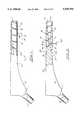
- FIG. 1is a side view of the preferred embodiment of the apparatus of the present invention
- FIG. 2is a partial cross-sectional view of the preferred apparatus of the present invention.
- FIG. 3is a side view of a second embodiment of the apparatus of the present invention that includes a proximally rigid component body and a modular, distally flexible sleeve component;
- FIG. 4is a cross-sectional view of a second embodiment of the present-invention.
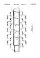
- FIG. 5is a partial side view of a second embodiment of the present invention that illustrates a modular, distally flexible sleeve with cross sections shown;
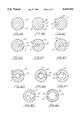
- FIG. 6Ais a cross-sectional view taken along lines A--A of FIG. 5;
- FIG. 6Bis a cross-sectional view taken along lines B--B of FIG. 5;
- FIG. 6Cis a cross-sectional view taken along lines C--C of FIG. 5;
- FIG. 6Dis a cross-sectional view taken along lines D--D of FIG. 5;
- FIG. 6Eis a cross-sectional view taken along lines E--E of FIG. 5;
- FIG. 6Fis a cross-sectional view taken along lines F--F of FIG. 5;
- FIG. 6Gis a cross-sectional view taken along lines G--G of FIG. 5;
- FIG. 6His a cross-sectional view taken along lines H--H of FIG. 5;
- FIG. 6Jis a cross-sectional view taken along lines J--J of FIG. 5;
- FIG. 6Kis a cross-sectional view taken along lines K--K of FIG. 5;
- FIG. 6Lis a cross-sectional view taken along lines L--L of FIG. 5;
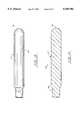
- FIG. 7is a side view of a third embodiment of the present invention, which illustrates the helical construct at a constant depth, coupled with a constant internal diameter;
- FIG. 8is a cross-sectional view of a third embodiment of the present invention.
- FIG. 9is a side view of a fourth embodiment of the apparatus of the present invention, which illustrates a helical construct with a variable depth coupled with a constant internal diameter
- FIG. 10is a cross-sectional view of a fourth embodiment of the apparatus of the present invention.
- FIG. 11is is a side view of a fifth embodiment of the apparatus of the present invention, which illustrates a helical construct with a variable depth coupled with a constant internal diameter, illustrating the variation that can be designed into the apparatus when compared to the fourth embodiment.
- FIG. 12is a cross-sectional view of the fifth embodiment of the apparatus of the present invention.
- FIG. 13is a side view of a unmodified stem portion
- FIG. 14is a cross-section view of an unmodified stem portion
- FIG. 15is a graphical illustration of the relationship between the distance (from mid-stem to distal tip) along the prosthesis and the moment of inertia of the prosthesis at the given distance for the four different embodiments of the present invention shown in FIGS. 5, 7, 9, and 11, as well as for the unmodified prosthesis shown in FIG. 13.
- FIGS. 1 and 2illustrate the preferred embodiment of the apparatus of the present invention designated generally by the numeral 10.
- a hip orthopaedic implantis shown in FIGS. 1 and 2.
- the implant 10has an upper proximal end portion 11 and a lower distal end portion 12.
- the upper end portion of prothesis 10is in the form of a hip implant having a thickened body portion 13.
- implant 10includes a neck region 14 for accepting a ball that registers with the patient's acetabulum.
- a continuous helical portion 28extends from cylindrical section 25 to distal end 12.
- Helical portion 28surrounds inner tapered bore portion 29.
- Tapered bore portion 29begins adjacent cylindrical section 25 at smaller diameter circular end portion 29A and extends to larger diameter portion 29B at distal end 12.
- the prosthesishas proximal 11 and distal 12 end portions.
- Proximal end portion 11has a lower tapered socket 15, with a smaller diameter section 16 and a larger diameter section 17 that communicates with open end 18.
- Socket 15 side wall 19is preferably tapered and shaped to receive section 21. Socket 15 forms a wedge lock or taper lock fit with conical section 21 of stem 20. Conical section 21 includes a smaller diameter end portion 22 and a larger diameter end portion 23.
- Annular shoulder 24is curved to form a transition between the conical surface 21 and the generally cylindrically shaped surface 25 shown in the drawings.
- a continuous helical portion 28extends from cylindrical section 25 to distal end 12.
- Helical portion 28surrounds inner tapered bore portion 29.
- Tapered bore portion 29begins adjacent cylindrical section 25 at smaller diameter circular end portion 29A and extends to larger diameter portion 29B at distal end 12.
- Helical portion 28 and conical portion 29are preferably integrally connected and can be of a metallic or composite construction, for example.
- a continuous spiralling recess 30defines a space that is also helical, the space 30 tracking the helical portion 28.
- the combination of helical portion 28 tapered conical bore section 29provides a means of varying the flexibility of stem 20 between end portion 22 and distal end 12.
- the helical portion 28could be made thicker between transverse faces 31, 32, that thickness dimension being designated by the numeral 33 in FIGS. 1-4.
- the conical bore sectioncan be varied in diameter with a smaller diameter at 29A and a larger diameter at 29B.
- FIGS. 6A to 6Lillustrate an example of the amount of cross-section (and thus mass moment of inertia) variation that can be introduced by the embodiment illustrated in FIGS. 3-5.
- FIGS. 7 and 8show an alternate stem 35 that can be used with the thickened body section 13 of FIGS. 3-5.
- Stem 35includes a proximal end 36 having a generally circular smaller diameter portion 37 and a generally circular larger diameter portion 40. This produces a frustroconically-shaped portion 41 that extends between the smaller diameter at 7 and the larger diameter at 40.
- Frustroconical portion 41can connect with a wedge-lock connection to socket 15 (FIG. 3).
- Stem 35includes a generally cylindrically shaped portion 42 and a continuous spiralling slot 43 that extends from cylindrical section 42 to distal end 38.
- the spiralling slot 43defines a helical construct 44 that has an inner surface 45 and an outer surface 50.
- the inner surface 45defines a cylindrically-shaped bore 46 that extends the length of the stem 35, having a central longitudinal bore axis 47.
- the proximal end 36includes a threaded section 49 that extends between the bore 46 and open end 48.
- the bore 46provides internal threads 49 that accommodate a removal tool should stem 35 be desirably removed from the patient's intramedullary canal after being implanted.
- a stem 51having a proximal end portion 52 and distal end portion 63.
- the stem proximal end portion 52includes a frustroconical section 53 that connects to a generally cylindrically-shaped section 54.
- Frustroconical section 53can be connected to socket 15 (FIG. 3) using a wedge-lock or taper lock connection.
- An elongated tapered core 55extends from the cylindrical section 54 in a direction toward the distal end portion.
- the frustroconical section 53includes larger diameter section 56 and smaller diameter section 57, providing a generally conically or frustroconically-shaped outer surface 58.
- Stem outer surface 59is generally cylindrically shaped at cylindrically-shaped section 54 but is in interrupted with spiralling slot 60 that initiates at cylindrical section 54 and proceeds to the distal tip end 63.
- the spiralling slot 60defines a helical construct 62 at bore 61.
- a generally cylindrically-shaped bore 61extends from closed end portion 73 and communicating with the open end 74 of bore 61.
- Stem 51 and bore 61share a common central longitudinal axis 64.
- a pair of spiralling shoulders 66, 67 and spiralling longitudinally extending surface 65define the boundaries of spiralling slot 60.
- a stem 77is provided having a proximal end portion 78 and distal end portion 79.
- the stem proximal end portion 78includes a frustroconical section 84 that connects to a generally cylindrically-shaped section 80.
- Frustroconical section 84can be connected to socket 15 (FIG. 3) using a wedge-lock or taper lock connection.
- An elongated tapered core 81extends from the cylindrical section 80 in a direction toward the distal end portion.
- the frustroconical section 84includes larger diameter section 82 and smaller diameter section 83, providing a generally conically or frustroconically-shaped outer surface.
- Stem outer surface 85is generally cylindrically shaped at cylindrically-shaped section 80 but is in interrupted with spiralling slot 86 that initiates at cylindrical section 80 and proceeds to the distal tip end 79.
- An enlarged, generally cylindrically-shaped bore 87extends from closed end portion 88 and communicating with the open end 89.
- Stem 77 and bore 87share a common central longitudinal axis 90.
- a pair of spiralling shoulders 91, 92 and spiralling longitudinally extending surface 93define the boundaries of spiralling slot 86.
- FIGS. 13-14a prior art type stem is shown, designated by the numeral 94.
- the stem 94has a frustroconical proximal end 95, a hemispherical end 96 and a cylindrical outer surface 97.
- FIG. 15there is seen a graphical representation of the moment of inertia, considering a stem that has a given distance from mid stem to distal tip.
- the x-axis 68represents the distance from mid stem to distal tip in inches and the moment of inertia is indicated at the y-axis 69.
- the black squares 70are data for the embodiment of FIG. 11.
- the black diamonds 72are data for the embodiment of FIG. 5.
- the white squares 71are data for the embodiment of FIG. 9.
- the white diamonds 75are data for the embodiment of FIG. 7.
- the black triangles 76are data for the embodiment of FIG. 13, which represents an unmodified cylindrical stem portion.
Landscapes
- Health & Medical Sciences (AREA)
- Orthopedic Medicine & Surgery (AREA)
- Cardiology (AREA)
- Oral & Maxillofacial Surgery (AREA)
- Transplantation (AREA)
- Engineering & Computer Science (AREA)
- Biomedical Technology (AREA)
- Heart & Thoracic Surgery (AREA)
- Vascular Medicine (AREA)
- Life Sciences & Earth Sciences (AREA)
- Animal Behavior & Ethology (AREA)
- General Health & Medical Sciences (AREA)
- Public Health (AREA)
- Veterinary Medicine (AREA)
- Prostheses (AREA)
Abstract
Description
1. Field of the Invention
The present invention relates to orthopaedic surgical implants and more particularly relates to an improved orthopaedic stem for use with an implant such as a hip implant or the like. Even more particularly the present invention relates to an improved flexible stem (or shaft) apparatus for use with an orthopaedic implant such as a hip implant wherein the stem includes a helical construct that will ultimately decrease the stiffness and thus improve the flexibility of the shaft portion of an orthopaedic implant.
2. General Background
Surgeons often implant surgical orthopaedic prosthetic devices that include a stem that occupies a portion of the patient's intramedullary canal. Examples include hip stems and tibial prosthetic stems. These prosthetic stems are well documented in the art as part of orthopaedic hip implants, knee implants and the like.
In the evolution of cementless femoral stem components, several problems have emerged. The main concerns are thigh pain and adaptive bone changes of proximal resorption and distal hypertrophy. Thigh pain has been attributed to some degree of instability between the femur and implant. Optimal stability can be achieved with modular components which permit ideal filling of the proximal and distal stem areas. A number of modular systems are now available through different manufacturers.
A growing body of literature supports the concept that flexibility of the stem tip is associated with a lower incidence of thigh pain. One study reports that once proximal bone ingrowth had occurred, severing the distal stem had no effect on the stability of the proximal implant and increased proximal strains. This is consistent with the concept that increasing flexibility at the stem tip combined with a rigid proximal metaphyseal portion will increase proximal load transfer.
One might infer that the stem is not necessary after bone ingrowth has occurred and an optimal stem should have a dissolvable distal stem. However, the distal stem is necessary for stability initially and probably to some extent long term. Applicant has observed late varus migration of certain prior art stems associated with poor filling of the stem tip on the lateral radiograph.
Stability of the stem within the patient's bone is achieved with optimal filling of the proximal and distal femur and may have little dependence on the elastic modulus of the stem material. Furthermore, optimal filling of the proximal and distal femur ensures that load is transferred to the proximal femur in both axial compression and torsion.
An ideal stem should thus consist of a flexible tip and rigid proximal section. This can be made with use of two different materials. A composite tip combined with a titanium proximal implant would achieve this. It also provides an opportunity for modularity, but presents a new interface since two materials contact one another. Designing a durable interface is essential to the feasibility of this implant.
Lack of adequate torsional stability in current stem designs is also a concern. Implants that increase torsional stability by obtaining distal fixation with extensively porous coated implants or distal flutes have been proposed. This is not ideal since torsional load transferred distally is unphysiologic and the proximal bone is stress shielded from torsional loads. A more physiologic stress transfer would ideally load the cortical bone of the calcar in combined axial compression and torsion.
Several patents have issued that relate generally to flexible femoral prostheses. U. K. Patent No. GB 2078523 B, entitled "Hip Joint Prosthesis", provides a hip joint prosthesis for replacement or restoration of the hip joint in a human body. The prosthesis includes a member that is adapted to be attached to the femur and a head portion adapted for cooperation with and movement relative to the acetabulum cavity of the pelvis or of a prosthesis defining such a cavity. The member has an elongated stem extending from the head portion and shaped for insertion into the medullary canal of the femur. The stem has a central axis and includes at least two rigid sections extending parallel to the axis and a resilient elastomeric material disposed between the rigid sections. The rigid sections are spaced laterally from the central axis and from each other.
U.K.Patent GB 2 239 398 A discloses a prosthetic implant having a varying modulus of elasticity. The implant has a shoulder portion and a stem portion comprising struts with a series of structures stacked thereon, the structures including both metal fiber structures and solid metallic structures which are arranged in such a manner that the flexural stiffness varies from one end of the stem to the other. Solid metal disks may alternate with fiber metal mesh disk regions. The relationship between the composite thickness of the mesh stacks and the thicknesses of solid disks determines the flexural stiffness in any particular region. Fiber metal segments of different thicknesses may alternate with solid metal plates. The implant may be particularly a hip prosthesis but may also be a knee, wrist, elbow, or shoulder prosthesis.
U.S. Pat. No. 4,292,695, entitled "Prosthesis Stem", provides an improved stem portion of a joint prosthesis for replacing a damaged or diseased skeletal joint, wherein a series of sections of elastomeric material attached to a rigid material are disposed one on top of the other in a staggered or offset configuration to form the stem. The offset is such that alternate sections of elastomer and rigid material contact selected locations of the bone within the medullary canal to firmly secure the prosthesis therewithin for resisting dislocation particularly during the early stages of postoperative rehabilitation.
U.S. Pat. No. 4,743,263, discloses an adaptable isoelastic hip endoprosthesis that comprises a joint piece connected to a shaft of the endoprosthesis which shaft is to be implanted in the femur, said shaft being composed of at least two spirally twisted elastic rods. Such rods can be of the same cross section, can have a variable cross section, and can have the same or different lengths.
U.S. Pat. No. 4,808,186, issued to T. S. Smith, provides a controlled stiffness elongated implant for use in the hip or other appropriate body joint. In the instance of the hip, a ball member fixed to the femur is rotatably engaged with a cup-shaped socket member fixed to the acetabulum of the pelvic bone. The ball member is mounted on one end of a femoral component which has an elongated stem receivable in the intramedullary canal of the femur. The stem has a longitudinal channel therein which lies generally in the coronal plane when the stem is in the implanted condition. The thickness of the stem laterally of the channel is variable between the proximal and distal ends so as to affect the moment of inertia at any given location along the length of said stem to thereby achieve stem flexibility which substantially correlates to the flexibility of the bone.
An orthopaedic prosthetic device possessing improved composite stem design is disclosed in U.S. Pat. No. 4,978,358. The surgical prosthetic device or implant of the '358 patent comprises a composite structure with an outer metallic component and a separate inner component comprised of the same or a different material. The outer component may be made of commercially pure titanium or a titanium alloy or of a cobalt-based alloy. The inner component may be made of a carbon composite material that may be reinforced or not reinforced with a polymeric material.
A load sharing femoral hip implant is disclosed in the Smith et al. U.S. Pat. No. 4,986,834. The '834 patent discloses a controlled stiffness elongated implant for use in the hip or other appropriate body joint. In the instance of the hip, a ball member fixed to the femur is rotatably engaged with a cup-shaped socket member fixed to the acetabulum of the pelvic bone. The ball member is mounted on one end of a femoral component which has an elongated stem receivable in the intramedullary canal of the femur. The stem has a generally longitudinally directed reduced mid-stem section. The dimension of the reduced mid-stem section is uniform or variable between the proximal and distal ends so as to affect the mass moment of inertia at any given location along the length of said stem to thereby achieve an optimal stem flexibility.
U.S. Pat. No. 5,030,234, entitled "Prosthetic Device With Modular Stem", provides a modular stem type prosthesis which includes a stem and an extension which are connected to one another with a slip fit interconnection that minimizes surface tensile forces in regions of the prosthesis adjacent the interface between the stem and the extension. Engagement between the stem and the extension is provided by deflectable end portions of one component of the prosthesis which are engaged in a mating structures may define an interfitting ridge and groove. Micromotion between the respective parts may be prevented by a screw which may be tapered to achieve a lock fit. The extension may be of any selected length and any selected diameter in accordance with the needs of the patient.
The present invention relates to a surgical orthopaedic implant and more particularly relates to an improved component that is designed to mechanically cooperate with the structural bending of the operated femur, tibia, and/or humerus to more closely reproduce the natural stress distributions seen in the host bone. These goals are accomplished through the controlled variation of properties specific to the distal portion of the implant, including, but not limited to variation in cross sectional area (and thus, mass moment of inertia).
In addition, other design features (to be discussed more fully hereinafter) can be varied to provide additional means of controlling component flexibility, allowing the component to more precisely match the properties of the host bone.
The stem or shaft apparatus includes a helical construct that gradually increases in depth beginning at the proximal end portion of the stem and ending at the distal end portion of the stem and wherein a helical portion surrounds the conical portion so that the combination of the conical portion and helical portion provide predictable flexibility between the proximal and distal end portions of the stem, the helical portion allowing easy removal of the stem from a patient's intramedullary canal if desired.
The preferred embodiment of the present invention includes the use of a stem that incorporates a spring-like helical construct with a constant outside diameter that is incorporated into the distal structure of a femoral, humeral, or tibial implant. The helix begins in the mid-portion of the stem, and proceeds distally to the tip of the stem.
The depth of the helix is varied as it proceeds to the distal tip of the implant, beginning with the a minimal depth at the most proximal portion of the helix, proceeding to a maximum depth at a point between the point of helix origin and the tip of the stem. At the point of maximum helix depth, a point defined by the transition from a solid metal core to an internal conical bore, the helix depth begins to decrease incrementally, arriving once again at a minimum value at the distal tip of the stem.
The preferred embodiment of the present invention includes the use of a modular metal stem extension that incorporates a spring-like helical construct with a constant outside diameter to be used in conjunction with a femoral, tibial, or humeral implant. The depth of the helix is controlled by the incorporation of a tapered cone (inherent to the helical structure) whose cross-section decreases towards the distal end of the sleeve, until, at some point, the cone tapers into and terminates within the helix. Distal to the tapered cone, the helix structure can form a simple helical compression spring structure with a rectangular cross section. The sleeve helix, including the distal tip portion of the helix, is constructed so that the sleeve can be removed from within the medullary canal by unscrewing the construct in much the same way a wood screw is removed from a wood structure.
This concept represents a definite improvement over current art in that it allows the distal portion of a stem to match the variational flexibility and stress distributions of a patient's femur.
The present invention thus provides an improved orthopaedic prosthesis for implantation in a patient's intramedullary canal. The apparatus includes a rigid proximal prosthesis body, and a distal shaft of variable flexibility.
In the preferred embodiment, a helical portion begins at the mid-portion of the apparatus, spiraling distally at a variably increasing depth until it reaches a maximum depth, at which point begins an internal conical bone that ultimately decreases the helix depth as one proceeds distally along the distal portion of the stem, arriving once again at a minimal helix depth at the tip of the stem.
A second embodiment of the present invention incorporates the helical structure described previously (with variable helix depth) into a modular distal stem construct that may be rigidly coupled to a prosthesis body by means of taper connection, threaded connection, or the like. In addition to the benefits obtained with the introduction of modularity, the helical stem extension offers another benefit. The extension helix, including the distal portion of the helix, is constructed such that the stem extension can be removed from within the medullary canal by unthreading the construct in much the same way a standard bolt is removed from a nut.
A number of other embodiments of the present invention can be described that couple some or all of the previously mentioned features with additional structural variations. Thus, a third embodiment may have a helix structure with a constant depth and a constant internal diameter. A fourth embodiment may incorporate the helix structure at a constant depth with a conical bore. A fifth embodiment may eliminate any internal material removal, allowing the helix depth to vary as one proceeds distally to the stem tip, terminating at the tip. Any number of additional variations can be made to the helix angle, helix gap width, helix lead length, etc. For example, two or more helixes (or helical slots) can be provided. These helixes could be both left hand or both right hand wound, in which case the prosthesis could be unscrewed to remove the prosthesis from the intramedullary canal. However, two or more helixes could be provided where one or more is right hand wound, and one or more is left hand wound in which case the prosthesis could not be removed by unscrewing it from the intramedullary canal.
In the preferred embodiment, the helical portion is in the form a regularly spaced continuous helical thread with flanges that are regularly spaced so that the prosthesis can be removed by rotation of the prosthesis so that the prosthesis simply unthreads much in the way that a bolt is unthreaded from a mating nut.
For a further understanding of the nature and objects of the present invention, reference should be had to the following detailed description taken in conjunction with the accompanying drawings, in which like parts are given like reference numerals, and wherein:
FIG. 1 is a side view of the preferred embodiment of the apparatus of the present invention;
FIG. 2 is a partial cross-sectional view of the preferred apparatus of the present invention;
FIG. 3 is a side view of a second embodiment of the apparatus of the present invention that includes a proximally rigid component body and a modular, distally flexible sleeve component;
FIG. 4 is a cross-sectional view of a second embodiment of the present-invention;
FIG. 5 is a partial side view of a second embodiment of the present invention that illustrates a modular, distally flexible sleeve with cross sections shown;
FIG. 6A is a cross-sectional view taken along lines A--A of FIG. 5;
FIG. 6B is a cross-sectional view taken along lines B--B of FIG. 5;
FIG. 6C is a cross-sectional view taken along lines C--C of FIG. 5;
FIG. 6D is a cross-sectional view taken along lines D--D of FIG. 5;
FIG. 6E is a cross-sectional view taken along lines E--E of FIG. 5;
FIG. 6F is a cross-sectional view taken along lines F--F of FIG. 5;
FIG. 6G is a cross-sectional view taken along lines G--G of FIG. 5;
FIG. 6H is a cross-sectional view taken along lines H--H of FIG. 5;
FIG. 6J is a cross-sectional view taken along lines J--J of FIG. 5;
FIG. 6K is a cross-sectional view taken along lines K--K of FIG. 5;
FIG. 6L is a cross-sectional view taken along lines L--L of FIG. 5;
FIG. 7 is a side view of a third embodiment of the present invention, which illustrates the helical construct at a constant depth, coupled with a constant internal diameter;
FIG. 8 is a cross-sectional view of a third embodiment of the present invention;
FIG. 9 is a side view of a fourth embodiment of the apparatus of the present invention, which illustrates a helical construct with a variable depth coupled with a constant internal diameter;
FIG. 10 is a cross-sectional view of a fourth embodiment of the apparatus of the present invention; and
FIG. 11 is is a side view of a fifth embodiment of the apparatus of the present invention, which illustrates a helical construct with a variable depth coupled with a constant internal diameter, illustrating the variation that can be designed into the apparatus when compared to the fourth embodiment.
FIG. 12 is a cross-sectional view of the fifth embodiment of the apparatus of the present invention.
FIG. 13 is a side view of a unmodified stem portion;
FIG. 14 is a cross-section view of an unmodified stem portion;
FIG. 15 is a graphical illustration of the relationship between the distance (from mid-stem to distal tip) along the prosthesis and the moment of inertia of the prosthesis at the given distance for the four different embodiments of the present invention shown in FIGS. 5, 7, 9, and 11, as well as for the unmodified prosthesis shown in FIG. 13.
FIGS. 1 and 2 illustrate the preferred embodiment of the apparatus of the present invention designated generally by the numeral 10. In FIGS. 1 and 2, a hip orthopaedic implant is shown. However, it should be understood that the present invention has utility with respect to other orthopaedic implants such as knee implants, shoulder implants and the like. In FIGS. 1 and 2, theimplant 10 has an upper proximal end portion 11 and a lowerdistal end portion 12. The upper end portion ofprothesis 10 is in the form of a hip implant having a thickenedbody portion 13.
In FIGS. 1-2,implant 10 includes aneck region 14 for accepting a ball that registers with the patient's acetabulum. In both embodiments of FIGS. 1-2 and 3-5, a continuoushelical portion 28 extends fromcylindrical section 25 todistal end 12.Helical portion 28 surrounds inner taperedbore portion 29.Tapered bore portion 29 begins adjacentcylindrical section 25 at smaller diametercircular end portion 29A and extends tolarger diameter portion 29B atdistal end 12. In the embodiment of FIGS. 3-4, designated by the numeral 10A, the prosthesis has proximal 11 and distal 12 end portions. Proximal end portion 11 has a lower tapered socket 15, with asmaller diameter section 16 and a larger diameter section 17 that communicates withopen end 18. Socket 15 side wall 19 is preferably tapered and shaped to receivesection 21. Socket 15 forms a wedge lock or taper lock fit withconical section 21 ofstem 20.Conical section 21 includes a smallerdiameter end portion 22 and a largerdiameter end portion 23.
In both embodiments of FIGS. 1-2 and 3-5, a continuoushelical portion 28 extends fromcylindrical section 25 todistal end 12.Helical portion 28 surrounds inner taperedbore portion 29.Tapered bore portion 29 begins adjacentcylindrical section 25 at smaller diametercircular end portion 29A and extends tolarger diameter portion 29B atdistal end 12.Helical portion 28 andconical portion 29 are preferably integrally connected and can be of a metallic or composite construction, for example.
Acontinuous spiralling recess 30 defines a space that is also helical, thespace 30 tracking thehelical portion 28. The combination ofhelical portion 28 taperedconical bore section 29 provides a means of varying the flexibility ofstem 20 betweenend portion 22 anddistal end 12. For example, thehelical portion 28 could be made thicker between transverse faces 31, 32, that thickness dimension being designated by the numeral 33 in FIGS. 1-4. Further, the conical bore section can be varied in diameter with a smaller diameter at 29A and a larger diameter at 29B.
FIGS. 6A to 6L illustrate an example of the amount of cross-section (and thus mass moment of inertia) variation that can be introduced by the embodiment illustrated in FIGS. 3-5.
FIGS. 7 and 8 show an alternate stem 35 that can be used with the thickenedbody section 13 of FIGS. 3-5. Stem 35 includes aproximal end 36 having a generally circularsmaller diameter portion 37 and a generally circularlarger diameter portion 40. This produces a frustroconically-shapedportion 41 that extends between the smaller diameter at 7 and the larger diameter at 40.Frustroconical portion 41 can connect with a wedge-lock connection to socket 15 (FIG. 3). Stem 35 includes a generally cylindrically shapedportion 42 and acontinuous spiralling slot 43 that extends fromcylindrical section 42 todistal end 38. The spirallingslot 43 defines ahelical construct 44 that has aninner surface 45 and an outer surface 50. Theinner surface 45 defines a cylindrically-shapedbore 46 that extends the length of the stem 35, having a central longitudinal bore axis 47. Theproximal end 36 includes a threadedsection 49 that extends between thebore 46 andopen end 48. Thebore 46 providesinternal threads 49 that accommodate a removal tool should stem 35 be desirably removed from the patient's intramedullary canal after being implanted.
In the embodiment of FIGS. 9 and 10, astem 51 is provided having aproximal end portion 52 and distal end portion 63. The stemproximal end portion 52 includes afrustroconical section 53 that connects to a generally cylindrically-shapedsection 54.Frustroconical section 53 can be connected to socket 15 (FIG. 3) using a wedge-lock or taper lock connection. An elongated taperedcore 55 extends from thecylindrical section 54 in a direction toward the distal end portion. Thefrustroconical section 53 includeslarger diameter section 56 and smaller diameter section 57, providing a generally conically or frustroconically-shaped outer surface 58.
Stemouter surface 59 is generally cylindrically shaped at cylindrically-shapedsection 54 but is in interrupted with spirallingslot 60 that initiates atcylindrical section 54 and proceeds to the distal tip end 63. The spirallingslot 60 defines a helical construct 62 at bore 61. A generally cylindrically-shaped bore 61 extends fromclosed end portion 73 and communicating with theopen end 74 of bore 61.Stem 51 and bore 61 share a common central longitudinal axis 64. A pair of spirallingshoulders slot 60.
In the embodiment of FIGS. 11 and 12, astem 77 is provided having aproximal end portion 78 anddistal end portion 79. The stemproximal end portion 78 includes afrustroconical section 84 that connects to a generally cylindrically-shapedsection 80.Frustroconical section 84 can be connected to socket 15 (FIG. 3) using a wedge-lock or taper lock connection. An elongated taperedcore 81 extends from thecylindrical section 80 in a direction toward the distal end portion. Thefrustroconical section 84 includeslarger diameter section 82 andsmaller diameter section 83, providing a generally conically or frustroconically-shaped outer surface.
Stemouter surface 85 is generally cylindrically shaped at cylindrically-shapedsection 80 but is in interrupted with spirallingslot 86 that initiates atcylindrical section 80 and proceeds to thedistal tip end 79. An enlarged, generally cylindrically-shapedbore 87 extends from closed end portion 88 and communicating with the open end 89.Stem 77 and bore 87 share a common central longitudinal axis 90. A pair of spirallingshoulders 91, 92 and spiralling longitudinally extendingsurface 93 define the boundaries of spirallingslot 86.
In FIGS. 13-14, a prior art type stem is shown, designated by the numeral 94. the stem 94 has a frustroconicalproximal end 95, ahemispherical end 96 and a cylindricalouter surface 97. In FIG. 15, there is seen a graphical representation of the moment of inertia, considering a stem that has a given distance from mid stem to distal tip. In FIG. 15, thex-axis 68 represents the distance from mid stem to distal tip in inches and the moment of inertia is indicated at the y-axis 69. Theblack squares 70 are data for the embodiment of FIG. 11. Theblack diamonds 72 are data for the embodiment of FIG. 5. Thewhite squares 71 are data for the embodiment of FIG. 9. Thewhite diamonds 75 are data for the embodiment of FIG. 7. Theblack triangles 76 are data for the embodiment of FIG. 13, which represents an unmodified cylindrical stem portion.
The following table lists the part numbers and part descriptions as used herein and in the drawings attached hereto.
______________________________________ PARTS LIST Part Number Description ______________________________________ 10 orthopaedic prosthesis 10A orthopaedic prosthesis 11 proximal end 12 distal end 13 thickened section 14 neck 15 socket 16 smaller diameter section 17 larger diameter section 18 open end 19 side wall 20 stem 21 conical section 22 smaller diameter end portion 23 larger diameter end portion 24 shoulder 25 cylindrical surface 28 helical portion 29 tapered bore portion 29A smaller diameter section 29B larger diameter section 30 spiralling recess 31 transverse face 32 transverse face 33 thickness 34 spiralling surface 35 stem 36 proximal end portion 37 smaller diameter section 38 distal end portion 40 larger diameter section 41 frustroconical section 42 cylindrically shaped portion 43 spiralling slot 44 helical construct 45 inner surface 46 bore 47 central longitudinal axis 48 open bore 49 internal threads 50 outer surface 51 stem 52 proximal end portion 53 frustroconical section 54 cylindrical section 55 tapered core 56 larger diameter section 57 smaller diameter section 58 conical outer surface 59 stem outer surface 60 spiralling slot 61 cylindrical bore 62 helical construct 63 distal end 64 central longitudinal axis 65 spiralling surface 66 spiralling shoulder 67 spiralling shoulder 68 x - axis 69 y - axis 70 black square 71 white square 72 black diamond 73 closed end 74 open end 75 white diamond 76 black triangle 77 stem 78 proximal end portion 79 distal end portion 80 cylindrical section 81 tapered core 82 larger diameter section 83 smaller diameter section 84 frustroconical section 85 stem outer surface 86 spiralling slot 87 cylindrical bore 88 closed end portion 89 open end 90 central longitudinal axis 91 spiralling shoulder 92 spiralling shoulder 93 spiralling surface 94 stem 95 frustroconical proximal end 96 hemispherical end 96 97 cylindrical outer surface ______________________________________
Because many varying and different embodiments may be made within the scope of the inventive concept herein taught, and because many modifications may be made in the embodiments herein detailed in accordance with the descriptive requirement of the law, it is to be understood that the details herein are to be interpreted as illustrative and not in a limiting sense.
Claims (12)
1. An orthopaedic prosthesis for implantation in a patient's intramedullary canal comprising
a) a prosthesis body that includes a generally rigid proximal portion sized and shaped to fit the intramedullary canal of a patient's bone;
b) prosthesis stem and mid portions on the prosthesis body, the stem portion including a lower elongated stem member with a an outer surface and distal end;
c) the lower stem member providing a helical groove and a cooperating hollowed tapered core portion that enable the distal end to flex; and
d) said helical groove extending between the outer surface of the stem and the hollowed core along a majority of the length of the hollowed core.
2. The prosthesis of claim 1 wherein the helical groove begins in the mid-portion of the prosthesis and proceeds distally to the tip of the stem.
3. The prosthesis of claim 2 wherein the depth of the helical groove is varied radially in thickness as it proceeds distally, beginning with a minimum depth at the most proximal portion of the helix.
4. The prosthesis of claim 1 wherein the core comprises a conically tapered bore with minimum and maximum diameter portion, said bore extending to the distal tip of the prosthesis, said bore terminating at the tip of the stem at said maximum inside diameter.
5. The prosthesis of claim 1 wherein the helical groove begins in the mid-portion of the prosthesis body and proceeds distally to the distal tip of the stem.
6. An orthopaedic prosthesis for implantation in a patient's intramedullary canal comprising:
a) a prosthesis body that includes a generally rigid proximal portion sized and shaped to fit the intramedullary canal of a patient's bone:
b) prosthesis stem and mid portions on the prosthesis body, the stem portion including a lower elongated stem member with a distal end;
c) the lower mid and stem member portions providing a helical groove and a cooperating core portion that enables the distal end to flex;
d) wherein the depth of the helical groove is varied in thickness radially as it proceeds distally, beginning with a minimum depth at the most proximal portion of the helix proceeding to a maximum depth at a point between the point of helix origin and the tip of the stem, where the internal core terminates.
7. The protheses of claim 1 wherein the core is conically shaped and tapered along the length thereof.
8. The prosthesis of claim 7 wherein the taper is a uniform taper beginning at a first diameter and tapering uniformally to a second diameter that is smaller that the first diameter.
9. The prosthesis of claim 1 wherein the body includes a neck portion having means thereon for attaching a prosthetic acetabular ball portion thereto.
10. The prosthesis of claim 1 wherein the helical groove includes a pair of generally parallel transverse face portions.
11. An orthopaedic hip prosthesis for implantation in a patient's femoral intramedullary canal comprising
a) a prosthesis body having a larger thickened central portion, an upper neck portion and a lower, smaller portion;
b) a prosthesis stem portion that extends from the smaller portion, and including an elongated stem member having an outer surface, proximal and distal ends, and an internal elongated hollow bore;
c) a helical groove portion that extends around the stem beginning at a position adjacent to the proximal end of the stem and terminating at a position adjacent to the distal end of the stem; and
d) wherein the bore is conically shaped, and the groove extends between the bore and the outer surface of the stem.
12. An orthopaedic hip prosthesis for implantation in a patient's femoral intramedullary canal comprising
a) a prosthesis body having a larger thickened central portion, an upper neck portion and a lower, smaller portion;
b) a prosthesis stem portion that extends from the smaller portion, and including an elongated stem member having an outer surface, proximal and distal ends, and an internal elongated hollow bore;
c) a helical groove portion that extends around the stem beginning at a position adjacent to the proximal end of the stem and terminating at a position adjacent to the distal end of the stem; and
d) wherein the groove continuously extends between the stem outer surface and the hollow bore.
Priority Applications (1)
| Application Number | Priority Date | Filing Date | Title |
|---|---|---|---|
| US08/328,363US5549702A (en) | 1994-10-25 | 1994-10-25 | Flexible orthopaedic stem apparatus |
Applications Claiming Priority (1)
| Application Number | Priority Date | Filing Date | Title |
|---|---|---|---|
| US08/328,363US5549702A (en) | 1994-10-25 | 1994-10-25 | Flexible orthopaedic stem apparatus |
Publications (1)
| Publication Number | Publication Date |
|---|---|
| US5549702Atrue US5549702A (en) | 1996-08-27 |
Family
ID=23280686
Family Applications (1)
| Application Number | Title | Priority Date | Filing Date |
|---|---|---|---|
| US08/328,363Expired - LifetimeUS5549702A (en) | 1994-10-25 | 1994-10-25 | Flexible orthopaedic stem apparatus |
Country Status (1)
| Country | Link |
|---|---|
| US (1) | US5549702A (en) |
Cited By (34)
| Publication number | Priority date | Publication date | Assignee | Title |
|---|---|---|---|---|
| EP0853931A3 (en)* | 1997-01-17 | 1999-03-17 | Stefano Orsi | Distal terminal element for the stem of a primary hip prosthesis |
| FR2799117A1 (en)* | 1999-09-30 | 2001-04-06 | Marc Andre Cahlik | Bone cavity plug comprises spiral of resorbable biocompatible material capable of radial expansion e.g. to support cement used with implant |
| US6245112B1 (en)* | 2000-02-29 | 2001-06-12 | Hammill Manufacturing Co. | Joint prosthesis variable flexibility |
| EP1013243A3 (en)* | 1998-12-21 | 2002-10-16 | Benoist Girard Sas | Femoral component for use in replacement hip joint |
| US20040078084A1 (en)* | 2002-10-22 | 2004-04-22 | Ricardo Albertorio | Prosthetic implant and method of use |
| WO2004064676A3 (en)* | 2003-01-22 | 2004-12-09 | Osteoimplant Technology Inc | Intrinsic stability in a total hip stem |
| US20050043811A1 (en)* | 2003-08-22 | 2005-02-24 | Doubler Robert L. | Welded hip prosthesis |
| US20060004465A1 (en)* | 2004-05-28 | 2006-01-05 | Alisha Bergin | Fluted intramedullary stem |
| US20070118229A1 (en)* | 2004-05-28 | 2007-05-24 | Smith & Nephew, Inc. | Fluted sleeve hip prosthesis for modular stem |
| US20070179627A1 (en)* | 2005-12-21 | 2007-08-02 | Gustilo Ramon B | Tibial component with a conversion module for a knee implant |
| US20080015707A1 (en)* | 2002-09-13 | 2008-01-17 | Richard Lambert | Hip prostheses |
| WO2007106408A3 (en)* | 2006-03-10 | 2008-07-10 | Poly 5 Group Llc | Intra-medullary implant with active compression |
| US20080281430A1 (en)* | 2005-02-22 | 2008-11-13 | Kelman David C | Long Sleeves for Use with Stems |
| US20090018546A1 (en)* | 2007-07-11 | 2009-01-15 | Daley Robert J | Methods and apparatus for determining pin placement during hip surgery |
| US8110005B2 (en) | 2000-04-10 | 2012-02-07 | Biomet Manufacturing Corp. | Modular prosthesis and use thereof for replacing a radial head |
| US8535382B2 (en) | 2000-04-10 | 2013-09-17 | Biomet Manufacturing, Llc | Modular radial head prostheses |
| US8778030B2 (en) | 2011-03-24 | 2014-07-15 | Christopher G. Sidebotham | Load bearing implants |
| US8906108B2 (en) | 2012-06-18 | 2014-12-09 | DePuy Synthes Products, LLC | Dual modulus hip stem and method of making the same |
| US8920509B2 (en) | 2000-04-10 | 2014-12-30 | Biomet Manufacturing, Llc | Modular radial head prosthesis |
| US9271839B2 (en) | 2013-03-14 | 2016-03-01 | DePuy Synthes Products, Inc. | Femoral component for an implantable hip prosthesis |
| US9345576B2 (en) | 2011-12-07 | 2016-05-24 | Smith & Nephew, Inc. | Orthopedic augments having recessed pockets |
| US9439781B2 (en) | 2011-05-03 | 2016-09-13 | Smith & Nephew, Inc. | Patient-matched guides for orthopedic implants |
| US20170056077A1 (en)* | 2015-07-13 | 2017-03-02 | IntraFuse, LLC | Flexible bone screw |
| US9707097B2 (en) | 2011-12-07 | 2017-07-18 | Smith & Nephew, Inc. | Orthopedic implant augments |
| CN107080606A (en)* | 2017-05-22 | 2017-08-22 | 北京爱康宜诚医疗器材有限公司 | Low elastic modulus femoral stem |
| US20180028321A1 (en)* | 2015-02-10 | 2018-02-01 | Jiangsu Okani Medical Technology Co., Ltd | Total hip surface replacement implant |
| US9901451B2 (en) | 2010-06-08 | 2018-02-27 | Smith & Nephew, Inc. | Implant components and methods |
| US10918763B2 (en) | 2015-02-10 | 2021-02-16 | Jiangsu Okani Medical Technology Co., Ltd | Combined fully organic high molecular material artificial knee joint |
| US20210338454A1 (en)* | 2015-10-21 | 2021-11-04 | Mca Group, Llc | 3d printed osteogenesis scaffold |
| USRE49239E1 (en) | 2009-02-25 | 2022-10-11 | Osteal Therapeutics, Inc. | Antibiotic delivery system and method for treating an infected synovial joint during re-implantation of an orthopedic prosthesis |
| US11504242B2 (en)* | 2015-06-17 | 2022-11-22 | Osteal Therapeutics, Inc. | Total joint replacement infection control devices and methods |
| EP4079262A4 (en)* | 2019-12-23 | 2023-02-01 | Hongwen Zhu | Flexible hip joint stem and hip joint prosthesis using same |
| US12208021B2 (en) | 2018-10-04 | 2025-01-28 | Depuy Ireland Unlimited Company | Prosthesis extraction system |
| US12239538B2 (en) | 2020-08-13 | 2025-03-04 | Osteal Therapeutics, Inc. | System and method for treatment and prevention of periprosthetic joint infections |
Citations (14)
| Publication number | Priority date | Publication date | Assignee | Title |
|---|---|---|---|---|
| EP0019042A1 (en)* | 1979-05-19 | 1980-11-26 | Sigri Elektrographit Gmbh | Femur part of a hip joint endoprosthesis |
| US4292695A (en)* | 1980-06-25 | 1981-10-06 | Lord Corporation | Prosthesis stem |
| GB2078523A (en)* | 1980-06-25 | 1982-01-13 | Lord Corp | Hip joint prosthesis |
| EP0077868A1 (en)* | 1981-10-26 | 1983-05-04 | Nunzio Godoli | Hip prosthesis as expanding femoral component |
| US4743263A (en)* | 1984-11-09 | 1988-05-10 | Ceske Vysoke Uceni Technicke | Adaptable isoelastic hip-endoprosthesis |
| US4784124A (en)* | 1985-07-16 | 1988-11-15 | Vereinigte Edelstahlwerke Aktiengesellschaft (Vew) | Bone implant for prostheses and tool for inserting the implant into a bone |
| US4808186A (en)* | 1988-02-02 | 1989-02-28 | Boehringer Mannheim Corporation | Controlled stiffness femoral hip implant |
| US4840633A (en)* | 1987-01-03 | 1989-06-20 | Manfred Kallabis | Cementless endoprosthesis |
| US4851008A (en)* | 1988-02-01 | 1989-07-25 | Orthomet, Inc. | Bone implant prosthesis with substantially stress-free outer surface |
| US4904268A (en)* | 1988-09-12 | 1990-02-27 | Alfredo Alvarado | Prosthetic device |
| US4978358A (en)* | 1988-10-06 | 1990-12-18 | Zimmer Inc. | Orthopaedic prosthetic device possessing improved composite stem design |
| US4986834A (en)* | 1988-08-31 | 1991-01-22 | Boehringer Mannheim Corporation | Load sharing femoral hip implant |
| GB2239398A (en)* | 1989-12-28 | 1991-07-03 | Bristol Myers Squibb Co | Prosthetic implant having varying modulus of elasticity |
| US5030234A (en)* | 1989-12-12 | 1991-07-09 | Pappas Michael J | Prosthetic device with modular stem |
- 1994
- 1994-10-25USUS08/328,363patent/US5549702A/ennot_activeExpired - Lifetime
Patent Citations (14)
| Publication number | Priority date | Publication date | Assignee | Title |
|---|---|---|---|---|
| EP0019042A1 (en)* | 1979-05-19 | 1980-11-26 | Sigri Elektrographit Gmbh | Femur part of a hip joint endoprosthesis |
| US4292695A (en)* | 1980-06-25 | 1981-10-06 | Lord Corporation | Prosthesis stem |
| GB2078523A (en)* | 1980-06-25 | 1982-01-13 | Lord Corp | Hip joint prosthesis |
| EP0077868A1 (en)* | 1981-10-26 | 1983-05-04 | Nunzio Godoli | Hip prosthesis as expanding femoral component |
| US4743263A (en)* | 1984-11-09 | 1988-05-10 | Ceske Vysoke Uceni Technicke | Adaptable isoelastic hip-endoprosthesis |
| US4784124A (en)* | 1985-07-16 | 1988-11-15 | Vereinigte Edelstahlwerke Aktiengesellschaft (Vew) | Bone implant for prostheses and tool for inserting the implant into a bone |
| US4840633A (en)* | 1987-01-03 | 1989-06-20 | Manfred Kallabis | Cementless endoprosthesis |
| US4851008A (en)* | 1988-02-01 | 1989-07-25 | Orthomet, Inc. | Bone implant prosthesis with substantially stress-free outer surface |
| US4808186A (en)* | 1988-02-02 | 1989-02-28 | Boehringer Mannheim Corporation | Controlled stiffness femoral hip implant |
| US4986834A (en)* | 1988-08-31 | 1991-01-22 | Boehringer Mannheim Corporation | Load sharing femoral hip implant |
| US4904268A (en)* | 1988-09-12 | 1990-02-27 | Alfredo Alvarado | Prosthetic device |
| US4978358A (en)* | 1988-10-06 | 1990-12-18 | Zimmer Inc. | Orthopaedic prosthetic device possessing improved composite stem design |
| US5030234A (en)* | 1989-12-12 | 1991-07-09 | Pappas Michael J | Prosthetic device with modular stem |
| GB2239398A (en)* | 1989-12-28 | 1991-07-03 | Bristol Myers Squibb Co | Prosthetic implant having varying modulus of elasticity |
Non-Patent Citations (2)
| Title |
|---|
| "Numerical Optimization Of Hip-Prosthetic Stem Material", J. H. Kuiper and R. Huiskes, pp. 76-84. |
| Numerical Optimization Of Hip Prosthetic Stem Material , J. H. Kuiper and R. Huiskes, pp. 76 84.* |
Cited By (77)
| Publication number | Priority date | Publication date | Assignee | Title |
|---|---|---|---|---|
| EP0853931A3 (en)* | 1997-01-17 | 1999-03-17 | Stefano Orsi | Distal terminal element for the stem of a primary hip prosthesis |
| US20070043448A1 (en)* | 1998-04-14 | 2007-02-22 | Encore Medical Asset Corporation | Intrinsic stability in a total hip stem |
| EP1013243A3 (en)* | 1998-12-21 | 2002-10-16 | Benoist Girard Sas | Femoral component for use in replacement hip joint |
| FR2799117A1 (en)* | 1999-09-30 | 2001-04-06 | Marc Andre Cahlik | Bone cavity plug comprises spiral of resorbable biocompatible material capable of radial expansion e.g. to support cement used with implant |
| US6245112B1 (en)* | 2000-02-29 | 2001-06-12 | Hammill Manufacturing Co. | Joint prosthesis variable flexibility |
| WO2001064139A3 (en)* | 2000-02-29 | 2002-02-07 | Hammill Mfg Co | Joint prosthesis having variable flexibility |
| WO2001064139A2 (en) | 2000-02-29 | 2001-09-07 | Hammill Manufacturing Co. | Joint prosthesis having variable flexibility |
| US8535382B2 (en) | 2000-04-10 | 2013-09-17 | Biomet Manufacturing, Llc | Modular radial head prostheses |
| US8425615B2 (en) | 2000-04-10 | 2013-04-23 | Biomet Manufacturing Corp. | Method and apparatus for adjusting height and angle for a radial head |
| US8920509B2 (en) | 2000-04-10 | 2014-12-30 | Biomet Manufacturing, Llc | Modular radial head prosthesis |
| US8110005B2 (en) | 2000-04-10 | 2012-02-07 | Biomet Manufacturing Corp. | Modular prosthesis and use thereof for replacing a radial head |
| US9333084B2 (en) | 2000-04-10 | 2016-05-10 | Biomet Manufacturing, Llc | Modular prosthesis and use thereof for replacing a radial head |
| US8114163B2 (en) | 2000-04-10 | 2012-02-14 | Biomet Manufacturing Corp. | Method and apparatus for adjusting height and angle for a radial head |
| US9579208B2 (en) | 2000-04-10 | 2017-02-28 | Biomet Manufacturing, Llc | Modular radial head prosthesis |
| US8366781B2 (en) | 2000-04-10 | 2013-02-05 | Biomet Manufacturing Corp. | Modular prosthesis and use thereof for replacing a radial head |
| US9439784B2 (en) | 2000-04-10 | 2016-09-13 | Biomet Manufacturing, Llc | Modular radial head prosthesis |
| US20080015707A1 (en)* | 2002-09-13 | 2008-01-17 | Richard Lambert | Hip prostheses |
| US8603182B2 (en) | 2002-09-13 | 2013-12-10 | Smith & Nephew, Inc. | Hip prostheses |
| US8753404B2 (en) | 2002-09-13 | 2014-06-17 | Smith & Nephew, Inc. | Hip prostheses |
| US20040078084A1 (en)* | 2002-10-22 | 2004-04-22 | Ricardo Albertorio | Prosthetic implant and method of use |
| EP1413263A1 (en)* | 2002-10-22 | 2004-04-28 | Zimmer Technology, Inc. | Prosthetic implant |
| WO2004064676A3 (en)* | 2003-01-22 | 2004-12-09 | Osteoimplant Technology Inc | Intrinsic stability in a total hip stem |
| US20050043811A1 (en)* | 2003-08-22 | 2005-02-24 | Doubler Robert L. | Welded hip prosthesis |
| US7033399B2 (en) | 2003-08-22 | 2006-04-25 | Ortho Innovations, Inc. | Welded hip prosthesis |
| US20060052877A9 (en)* | 2003-08-22 | 2006-03-09 | Doubler Robert L | Welded hip prosthesis |
| US7575603B2 (en) | 2004-05-28 | 2009-08-18 | Smith & Nephew, Inc. | Fluted intramedullary stem |
| US20110144762A1 (en)* | 2004-05-28 | 2011-06-16 | Smith & Nephew, Inc. | Fluted sleeve hip prosthesis for modular stem |
| US20070118229A1 (en)* | 2004-05-28 | 2007-05-24 | Smith & Nephew, Inc. | Fluted sleeve hip prosthesis for modular stem |
| US8641773B2 (en) | 2004-05-28 | 2014-02-04 | Smith & Nephew, Inc. | Fluted sleeve hip prosthesis for modular stem |
| US20090270860A1 (en)* | 2004-05-28 | 2009-10-29 | Smith & Nephew, Inc | Fluted intramedullary stem |
| US7892290B2 (en) | 2004-05-28 | 2011-02-22 | Smith & Nephew, Inc. | Fluted sleeve hip prosthesis for modular stem |
| US20060004465A1 (en)* | 2004-05-28 | 2006-01-05 | Alisha Bergin | Fluted intramedullary stem |
| US20080281430A1 (en)* | 2005-02-22 | 2008-11-13 | Kelman David C | Long Sleeves for Use with Stems |
| US20070179627A1 (en)* | 2005-12-21 | 2007-08-02 | Gustilo Ramon B | Tibial component with a conversion module for a knee implant |
| US9241800B2 (en) | 2005-12-21 | 2016-01-26 | Orthopaedic International Inc. | Tibial component with a conversion module for a knee implant |
| WO2007106408A3 (en)* | 2006-03-10 | 2008-07-10 | Poly 5 Group Llc | Intra-medullary implant with active compression |
| US8998916B2 (en) | 2007-07-11 | 2015-04-07 | Smith & Nephew, Inc. | Methods for determining pin placement during hip surgery |
| US9439657B2 (en) | 2007-07-11 | 2016-09-13 | Smith & Nephew, Inc. | Methods and apparatus for determining pin placement during hip surgery |
| US8882780B2 (en) | 2007-07-11 | 2014-11-11 | Smith & Nephew, Inc. | Methods and apparatus for determining pin placement during hip surgery |
| US20090018546A1 (en)* | 2007-07-11 | 2009-01-15 | Daley Robert J | Methods and apparatus for determining pin placement during hip surgery |
| US20110208201A1 (en)* | 2007-07-11 | 2011-08-25 | Smith & Nephew, Inc. | Methods for determining pin placement during hip surgery |
| USRE50051E1 (en) | 2009-02-25 | 2024-07-23 | Osteal Therapeutics, Inc. | Antibiotic delivery system and method for treating an infected synovial joint during re-implantation of an orthopedic prosthesis |
| USRE49239E1 (en) | 2009-02-25 | 2022-10-11 | Osteal Therapeutics, Inc. | Antibiotic delivery system and method for treating an infected synovial joint during re-implantation of an orthopedic prosthesis |
| US9901451B2 (en) | 2010-06-08 | 2018-02-27 | Smith & Nephew, Inc. | Implant components and methods |
| US8778030B2 (en) | 2011-03-24 | 2014-07-15 | Christopher G. Sidebotham | Load bearing implants |
| US9439781B2 (en) | 2011-05-03 | 2016-09-13 | Smith & Nephew, Inc. | Patient-matched guides for orthopedic implants |
| US9345576B2 (en) | 2011-12-07 | 2016-05-24 | Smith & Nephew, Inc. | Orthopedic augments having recessed pockets |
| US10265178B2 (en) | 2011-12-07 | 2019-04-23 | Smith & Nephew, Inc. | Orthopedic augments having recessed pockets |
| US9707097B2 (en) | 2011-12-07 | 2017-07-18 | Smith & Nephew, Inc. | Orthopedic implant augments |
| US11344432B2 (en) | 2011-12-07 | 2022-05-31 | Smith & Nephew, Inc. | Orthopedic implant augments |
| US11135067B2 (en) | 2011-12-07 | 2021-10-05 | Smith & Nephew, Inc. | Orthopedic augments having recessed pockets |
| US9814582B2 (en) | 2011-12-07 | 2017-11-14 | Smith & Nephew, Inc. | Orthopedic augments having recessed pockets |
| US9848989B2 (en) | 2011-12-07 | 2017-12-26 | Smith & Nephew, Inc. | Orthopedic augments having recessed pockets |
| US10383744B2 (en) | 2011-12-07 | 2019-08-20 | Smith & Nephew, Inc. | Orthopedic implant augments |
| US12232978B2 (en) | 2011-12-07 | 2025-02-25 | Smith & Nephew, Inc. | Orthopedic implant augments |
| US10213310B2 (en) | 2012-06-18 | 2019-02-26 | DePuy Synthes Products, Inc. | Dual modulus hip stem and method of making the same |
| US11020232B2 (en) | 2012-06-18 | 2021-06-01 | DePuy Synthes Products, Inc. | Dual modulus hip stem and method of making the same |
| US8906108B2 (en) | 2012-06-18 | 2014-12-09 | DePuy Synthes Products, LLC | Dual modulus hip stem and method of making the same |
| US9132013B2 (en) | 2012-06-18 | 2015-09-15 | DePuy Synthes Products, Inc. | Dual modulus hip stem |
| US9717597B2 (en) | 2013-03-14 | 2017-08-01 | DePuy Synthes Products, Inc. | Femoral component for an implantable hip prosthesis |
| US9271839B2 (en) | 2013-03-14 | 2016-03-01 | DePuy Synthes Products, Inc. | Femoral component for an implantable hip prosthesis |
| US11058543B2 (en) | 2013-03-14 | 2021-07-13 | DePuy Synthes Products, Inc. | Femoral component for an implantable hip prosthesis and method of making same |
| US12295851B2 (en) | 2013-03-14 | 2025-05-13 | DePuy Synthes Products, Inc. | Femoral component for an implantable hip prosthesis and method of making same |
| US10213314B2 (en) | 2013-03-14 | 2019-02-26 | DePuy Synthes Products, Inc. | Femoral component for an implantable hip prosthesis |
| US20180028321A1 (en)* | 2015-02-10 | 2018-02-01 | Jiangsu Okani Medical Technology Co., Ltd | Total hip surface replacement implant |
| US11318021B2 (en)* | 2015-02-10 | 2022-05-03 | Jiangsu Okani Medical Technology Co., Ltd | Total hip surface replacement implant |
| US10918763B2 (en) | 2015-02-10 | 2021-02-16 | Jiangsu Okani Medical Technology Co., Ltd | Combined fully organic high molecular material artificial knee joint |
| US12383404B2 (en) | 2015-06-17 | 2025-08-12 | Osteal Therapeutics, Inc. | Total joint replacement infection control devices and methods |
| US12257154B2 (en) | 2015-06-17 | 2025-03-25 | Osteal Therapeutics, Inc. | Total joint replacement infection control devices and methods |
| US11504242B2 (en)* | 2015-06-17 | 2022-11-22 | Osteal Therapeutics, Inc. | Total joint replacement infection control devices and methods |
| US10154863B2 (en)* | 2015-07-13 | 2018-12-18 | IntraFuse, LLC | Flexible bone screw |
| US20170056077A1 (en)* | 2015-07-13 | 2017-03-02 | IntraFuse, LLC | Flexible bone screw |
| US20210338454A1 (en)* | 2015-10-21 | 2021-11-04 | Mca Group, Llc | 3d printed osteogenesis scaffold |
| CN107080606A (en)* | 2017-05-22 | 2017-08-22 | 北京爱康宜诚医疗器材有限公司 | Low elastic modulus femoral stem |
| US12208021B2 (en) | 2018-10-04 | 2025-01-28 | Depuy Ireland Unlimited Company | Prosthesis extraction system |
| EP4079262A4 (en)* | 2019-12-23 | 2023-02-01 | Hongwen Zhu | Flexible hip joint stem and hip joint prosthesis using same |
| US12239538B2 (en) | 2020-08-13 | 2025-03-04 | Osteal Therapeutics, Inc. | System and method for treatment and prevention of periprosthetic joint infections |
Similar Documents
| Publication | Publication Date | Title |
|---|---|---|
| US5549702A (en) | Flexible orthopaedic stem apparatus | |
| US12396860B2 (en) | Modular rotational device for torsionally stabilizing an endoprosthesis | |
| US8157871B2 (en) | Femoral HIP prosthesis and method of implantation | |
| EP1216668B1 (en) | Prosthesis with feature aligned to trabeculae | |
| US5683466A (en) | Joint surface replacement system | |
| US5593451A (en) | Prosthetic device and method of implantation | |
| AU2003235084B2 (en) | Prosthetic stem with bearing | |
| CA2120706C (en) | Reduced stiffness femoral hip implant | |
| US5092899A (en) | Prosthesis with flexible intramedullary stem | |
| US4986834A (en) | Load sharing femoral hip implant | |
| US6245112B1 (en) | Joint prosthesis variable flexibility | |
| US6887278B2 (en) | Prosthetic implant having segmented flexible stem | |
| US6656187B1 (en) | Adjustable orthopaedic instrument | |
| US8778030B2 (en) | Load bearing implants | |
| EP0358399A1 (en) | Load sharing femoral hip implant | |
| NL2036988B1 (en) | Intramedullary implant | |
| JP2002291778A (en) | Artificial organ, stem of artificial organ, and manufacturing method of artificial organ | |
| AU2011223978A1 (en) | Femoral hip prosthesis and method of implantation | |
| AU2006200192B2 (en) | Prosthesis with surface feature |
Legal Events
| Date | Code | Title | Description |
|---|---|---|---|
| AS | Assignment | Owner name:SMITH & NEPHEW RICHARDS INC., TENNESSEE Free format text:ASSIGNMENT OF ASSIGNORS INTEREST;ASSIGNOR:TOKISH, LEONARD J., JR.;REEL/FRAME:007243/0094 Effective date:19941020 Owner name:SMITH & NEPHEW RICHARDS INC., TENNESSEE Free format text:ASSIGNMENT OF ASSIGNORS INTEREST;ASSIGNOR:RIES, MICHAEL D.;REEL/FRAME:007243/0091 Effective date:19941010 Owner name:SMITH & NEPHEW RICHARDS INC., TENNESSEE Free format text:ASSIGNMENT OF ASSIGNORS INTEREST;ASSIGNOR:FALLIN, THOMAS WADE;REEL/FRAME:007243/0088 Effective date:19941013 | |
| STCF | Information on status: patent grant | Free format text:PATENTED CASE | |
| FPAY | Fee payment | Year of fee payment:4 | |
| FPAY | Fee payment | Year of fee payment:8 | |
| FPAY | Fee payment | Year of fee payment:12 |