US5549659A - Communication interface for transmitting and receiving serial data between medical instruments - Google Patents
Communication interface for transmitting and receiving serial data between medical instrumentsDownload PDFInfo
- Publication number
- US5549659A US5549659AUS08/334,623US33462394AUS5549659AUS 5549659 AUS5549659 AUS 5549659AUS 33462394 AUS33462394 AUS 33462394AUS 5549659 AUS5549659 AUS 5549659A
- Authority
- US
- United States
- Prior art keywords
- leaf spring
- communication circuit
- coupled
- serial communication
- leaf
- Prior art date
- Legal status (The legal status is an assumption and is not a legal conclusion. Google has not performed a legal analysis and makes no representation as to the accuracy of the status listed.)
- Expired - Lifetime
Links
Images


Classifications
- A—HUMAN NECESSITIES
- A61—MEDICAL OR VETERINARY SCIENCE; HYGIENE
- A61N—ELECTROTHERAPY; MAGNETOTHERAPY; RADIATION THERAPY; ULTRASOUND THERAPY
- A61N1/00—Electrotherapy; Circuits therefor
- A61N1/18—Applying electric currents by contact electrodes
- A61N1/32—Applying electric currents by contact electrodes alternating or intermittent currents
- A61N1/38—Applying electric currents by contact electrodes alternating or intermittent currents for producing shock effects
- A61N1/39—Heart defibrillators
- A61N1/3925—Monitoring; Protecting
- A—HUMAN NECESSITIES
- A61—MEDICAL OR VETERINARY SCIENCE; HYGIENE
- A61N—ELECTROTHERAPY; MAGNETOTHERAPY; RADIATION THERAPY; ULTRASOUND THERAPY
- A61N1/00—Electrotherapy; Circuits therefor
- A61N1/18—Applying electric currents by contact electrodes
- A61N1/32—Applying electric currents by contact electrodes alternating or intermittent currents
- A61N1/38—Applying electric currents by contact electrodes alternating or intermittent currents for producing shock effects
- A61N1/39—Heart defibrillators
- A61N1/3904—External heart defibrillators [EHD]
- A—HUMAN NECESSITIES
- A61—MEDICAL OR VETERINARY SCIENCE; HYGIENE
- A61N—ELECTROTHERAPY; MAGNETOTHERAPY; RADIATION THERAPY; ULTRASOUND THERAPY
- A61N1/00—Electrotherapy; Circuits therefor
- A61N1/18—Applying electric currents by contact electrodes
- A61N1/32—Applying electric currents by contact electrodes alternating or intermittent currents
- A61N1/36—Applying electric currents by contact electrodes alternating or intermittent currents for stimulation
- A61N1/372—Arrangements in connection with the implantation of stimulators
- A61N1/37211—Means for communicating with stimulators
- A—HUMAN NECESSITIES
- A61—MEDICAL OR VETERINARY SCIENCE; HYGIENE
- A61N—ELECTROTHERAPY; MAGNETOTHERAPY; RADIATION THERAPY; ULTRASOUND THERAPY
- A61N1/00—Electrotherapy; Circuits therefor
- A61N1/18—Applying electric currents by contact electrodes
- A61N1/32—Applying electric currents by contact electrodes alternating or intermittent currents
- A61N1/38—Applying electric currents by contact electrodes alternating or intermittent currents for producing shock effects
- A61N1/39—Heart defibrillators
- A61N1/3968—Constructional arrangements, e.g. casings
Definitions
- the present inventionrelates to connectors and associated communication circuits for transmitting data between interconnectable medical instruments.
- the LIFEPAK 5® monitor and defibrillator produced by Physio-Control Corporation of Redmond, Wash.is a multicomponent medical instrument having an EKG monitor and a defibrillator.
- the monitorrecords and analyzes a patient's EKG signal while the defibrillator produces a high energy defibrillation pulse to terminate ventricular or atrial fibrillation.
- the LIFEPAK 5® monitor and defibrillatorcan be secured together as a single unit, having both monitoring and defibrillation capability. Alternatively, each component may be used separately when only one function is desired. Details of the interconnection are described in U.S. Pat. Nos. 4,096,856 and 4,097,113, which are expressly incorporated by reference herein.
- the top two contactsare used to transmit EKG data received from the defibrillator's hard paddles to the monitor.
- the center contactsare connected to isolated ground.
- the bottom two contactsare dedicated to operation of the instrument in a "synchronized cardioversion mode" in which the EKG monitor analyzes the EKG data from the top contacts or other EKG input and transmits a "sync pulse" to the defibrillator by way of the bottom contact when an R wave in a QRS complex is detected.
- the defibrillatorsignals the monitor that synchronized cardioversion mode is selected by applying a D.C. voltage signal to the contact immediately above the bottom sync pulse contact. Upon receipt of a sync pulse, the defibrillator delivers a defibrillation pulse to the patient.
- the present inventionprovides an improved communication interface that transmits coded serial data between two connectable medical instruments.
- the interfaceis comprised of two corresponding sets of contacts located on opposing surfaces of the medical instruments. When the medical instruments are coupled together, the sets of contacts of the communication interface are engaged. Each set of contacts includes a plurality of vertically aligned, horizontally extending leaf spring contacts.
- a serial data transfer circuit in each medical instrumentincludes a transmit output coupled to one of the leaf springs and a receive input coupled to another of the leaf springs. When the medical instruments are connected, the transmit outputs of the serial data transfer circuit are coupled to the receive inputs of a corresponding serial data transfer circuit.
- one communication interfaceincludes an input-output port having an input pin coupled to the receive input on the serial data transfer circuit and an output pin coupled to the same leaf spring as the transmit output of the serial data transfer circuit.
- a microprocessorreads the input pin of the input-output port to determine if the connected medical instrument is requesting that signals be sent in a nonserial format. If so, the communication interface transmits signals to the connected medical instrument by toggling the output pin on the input-output port.
- the resultis a set of interconnectable components that can be used independently, or which can be joined to function cooperatively by the interchange of coded serial data.
- the monitorcan still be used with less sophisticated defibrillators which do not have serial data transfer capacity.
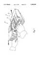
- FIG. 1is a perspective of an interconnectable EKG monitor and defibrillator having a communication interface for transmitting and receiving serial data between medical instruments in accordance with the present invention
- FIG. 2is a fragmentary perspective view of the mating communication interface of FIG. 1;
- FIG. 3is a diagrammatic perspective of a prior art electrical connector that transmits electrical signals between an EKG monitor and defibrillator;
- FIG. 4is a diagrammatic perspective showing how an electrical connector of the present invention is used to transmit serial data between a pair of medical instruments
- FIG. 5is a block diagram of a communication circuit that transmits and receives serial data from a medical instrument coupled to the connector according to the present invention
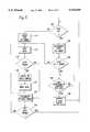
- FIG. 6is a flow chart showing the steps performed by the communication circuit shown in FIG. 5 to determine whether a connected medical instrument is transmitting serial data
- FIG. 7(on the drawing sheet with FIG. 5) is a block diagram of a communication circuit used to transmit serial data to, and receive serial data from, the communication circuit shown in FIG. 5.
- FIG. 1shows a multicomponent medical instrument having a communication interface for transmitting and receiving serial data between medical instruments in accordance with the present invention.
- the medical instrumentincludes an electrocardiogram (EKG) monitor 10 and a defibrillator 12.
- EKG monitor 10 and defibrillator 12are secured together by a cooperating tongue and groove found on opposing surfaces of the respective components.
- the defibrillator 12has a side face 13 that abuts a side face 11 on the EKG monitor 10 when the defibrillator is secured to the EKG monitor.
- a groove 15that cooperates with a tongue 17 disposed on the bottom surface of the EKG monitor 10. Additional details of the tongue and groove connection are set forth in U.S. Pat. No. 4,096,845.
- an electrical connector 25is provided.
- the electrical connectoris comprised of two sets of vertically aligned, horizontally extending leaf springs.
- a first set of leaf springs 25a, found on the EKG monitorincludes five horizontally extending leaf springs 30, 32, 34, 36 and 38.
- a second set of leaf springs 25bthat includes five vertically aligned, horizontally extending leaf springs 40, 42, 44, 46 and 48.
- leaf spring 30engages leaf spring 40
- leaf spring 32engages leaf spring 42
- leaf spring 34engages leaf spring 44
- leaf spring 36engages leaf spring 46
- leaf spring 38engages leaf spring 48.
- leaf springs 40, 42, 44, 46 and 48are described as being disposed on a defibrillator, those skilled in the art will recognize that the leaf springs could be disposed on other types of medical instruments such as cardiac pacers, etc.
- the EKG monitor 10senses the patient's electrocardiogram signal through a set of EKG electrodes (not shown).
- the EKG monitordisplays the patient's electrocardiogram signal on a display screen for a physician or medical technician to observe. If desired, the electrocardiogram signal can be primed on a strip chart.
- the defibrillator 12includes a pair of paddles 14 (see on FIG. 1) used to apply a defibrillation pulse to the patient if necessary.
- the defibrillation paddles 14can be used to sense a patient's electrocardiogram signal if no special purpose EKG leads are available.
- the electrocardiogram signal sensed by the defibrillation paddlesis transferred from the defibrillator to the EKG monitor via the electrical connector when the defibrillator 12 is coupled to the EKG monitor 10.
- the prior art LIFEPAK 5® monitor and defibrillatoruses essentially the same arrangement of leaf spring contacts as the communication interface of the present invention, but the contacts are dedicated to different operations.
- the leaf springs 34 and 44are grounded to provide a reference potential.
- Electrocardiogram signals received from hard paddles on the defibrillatorare transmitted from leaf spring 40 on the defibrillator to leaf spring 30 on the EKG monitor and from leaf spring 42 on the defibrillator to leaf spring 32 on the EKG monitor.
- the defibrillator 12can be set to provide a synchronized defibrillation pulse that is delivered at a predefined time after an R wave in the patient's EKG signal is detected.
- a D.C. logic signal "sync on”is applied to leaf spring 46 and is received by the EKG monitor on leaf spring 36.
- the EKG monitordetermines whether the defibrillator is in synchronized cardioversion mode by reading the voltage on leaf spring 36. If the defibrillator is operating in the synchronized cardioversion mode, the EKG monitor analyzes the EKG signals received on leaf springs 30 and 32 in order to detect the occurrence of an R wave. Once an R wave has been detected, the EKG monitor applies the "sync pulse" on leaf spring 38, which is received on leaf spring 48, thereby causing the defibrillation pulse to be applied to the patient at the correct time.
- the EKG monitor in accordance with the present inventionhas the ability to transmit and receive coded serial data with a cooperating medical instrument.
- This coded serial datamay include indications of the status of an instrument, operating instructions entered by a user, physiological signals received by the instrument, etc.
- the communication circuit formerly used to drive the electrical connector 25 shown in FIG. 3does not allow for the transfer and receipt of serial data. Therefore, the present invention is an improvement of the communication circuit to allow serial data to be transmitted between medical instruments equipped with similar connectors.
- a communication circuit coupled to the connectordetects whether an attached medical instrument is transmitting serial data or is expecting a sync pulse to be transmitted as a change in logic levels on one of the leaf springs of the connector.
- the electrical connector 25 used in the present inventionis physically unchanged from the electrical connector shown in FIG. 3 and described above.
- the left side of the connector 25 found in the EKG monitoris driven by a communication circuit (not shown) having the ability to receive serial data on the leaf spring 36 and transmit serial data on the leaf spring 38.
- the right side of the connector 25is found in a defibrillator or other medical instrument that is coupled to the EKG monitor.
- a communication circuit (also not shown) within the defibrillatortransmits serial data from leaf spring 46 and receives serial data on leaf spring 48.
- a communication circuit 50 found in the EKG monitorincludes a central processing unit (CPU) 60, an input-output port 64, a UART 66 and a NOR gate 68.
- the CPU 60is coupled to the input-output port 64 and the UART 66 via a set of data/address leads 62.
- a receive data pin (RxD) on the UART 66is coupled through an isolation circuit 70 to the leaf spring 36.
- a transmit pin (TxD) pin of the UART 66is coupled to an input of the NOR gate 68.
- the output of the NOR gateis coupled through an isolation circuit 72 to the leaf spring 38.
- Another input of the NOR gate 68is coupled to an output pin 64b of the input-output port 64.
- An input pin 64a of the input-output port 64is coupled through an inverter 74 to the RxD pin on the UART 66.
- the isolation circuits 70 and 72preferably comprise known optoisolation circuits.
- the communication circuit 50operates to transmit and receive both serial data from medical instruments having this capability, and to receive EKG data and provide sync pulses to defibrillators that do not have serial data transfer capability.
- the CPU 60reads the input pin 64a of the input-output port 64. If a logic high signal is detected for more than a predetermined duration, the EKG monitor assumes the defibrillator is operating in the synchronized cardioversion mode. When an R wave is detected in the patient's EKG wave form, the CPU transmits a sync pulse by strobing the output pin 64b on the input-output port 64.
- the CPUtransfers parallel data over the set of data/address leads 62 to the UART 66. The UART serializes and transmits the data.
- FIG. 6is a flow chart showing the steps performed by the CPU 60 within the communication circuit 50 to determine whether a connected medical instrument is transmitting serial data or is requesting a sync pulse to be provided on leaf spring 38.
- the CPUsamples the voltage on input pin 64a (shown in FIG. 5) to determine whether a "sync on" signal is present on leaf spring 36. If the sync on signal is present, an internal timer within the CPU is incremented at a step 102.
- the CPUdetermines whether the sync on signal has been present for more than a predefined period, such as 200 milliseconds. If not, the CPU jumps to step 116 to determine whether the serial data has been received by the UART as will be described below.
- the CPUproceeds from step 104 to a step 106 that analyzes the patient's EKG signal.
- the EKG datais analyzed for the presence of an R wave within a QRS complex according to techniques well known to those skilled in the art of medical electronics. If no R wave is detected, the CPU continues to analyze the EKG data until an R wave is detected.
- the CPUUpon the detection of an R wave, the CPU outputs a sync pulse by toggling the voltage on the output pin 64b of the input-output port 64 (shown in FIG. 5) at a step 108.
- the sync pulseinforms the defibrillator that it should apply a defibrillation pulse to the patient.
- the CPUloops back to step 100 and determines whether the "sync on" signal is still present.
- the CPUIf no "sync on" signal is detected at step 100, the CPU resets the sync on timer at a step 114. The CPU then polls the UART at a step 116 and determines whether serial data has been received. If data has been received, the CPU then determines whether the received data is ready to be read by the CPU at a step 118. If data is ready to be read, the CPU resets a "no data" timer at a step 120 and reads the received data from the UART at a step 122. After the data has been read, the CPU loops back to step 116 and polls the UART to determine if more data has been received.
- the CPUincrements the "no data" timer that tracks the time since data has been received at a step 130.
- the CPUdetermines whether more than a predefined period, such as 600 milliseconds, has passed since serial data was received by the UART. If time between the last serial data transmission is less than the predefined period, the CPU loops back to step 116 and polls the UART to see if a new serial data transmission has been received. If more than the predefined period has passed since the last serial data transmission, the CPU loops back to step 100 and again determines whether the "sync on" signal is present on leaf spring 36. Initially, the "no data" timer is set to a value more than the predetermined time (i.e., 660 milliseconds) so that if no data is received by the UART on the first pass, the answer to step 132 will be yes.
- a predefined periodsuch as 600 milliseconds
- the communication circuit within the EKG monitormonitors whether a medical instrument connected to it is transmitting serial data or is operating in a synchronized cardioversion mode and is requesting a sync pulse to be transmitted upon detection of an R wave.
- the sync code signalis encoded as a serial data packet that is transmitted from the EKG monitor to the defibrillator.
- FIG. 7is a block diagram of a communications circuit 150 found within a medical instrument that couples to and communicates with the communication circuit 50 shown in FIG. 5.
- the communication circuit 150includes a CPU 152 coupled to a UART 156 via a set of address/data leads 154.
- the CPU 152is preferably a model No. MC68HC11 produced by Motorola, and the UART 156 is preferably a model No. 68HC11 internal UART produced by Motorola.
- UART 156is shown as a separate component in FIG. 7 for ease of illustration. Those skilled in the art will appreciate that other CPUs and UARTs could also be used.
- a receive data pin (RxD) on the UARTis coupled to the leaf spring 48 through an isolation circuit 160.
- a transmit output pin (TxD) on the UARTis coupled to the leaf spring 46 through the isolation circuit 158.
- the CPU 152controls the operation of a medical instrument such as a defibrillator 170 in a manner well known to those of ordinary skill in the art. Data to be transmitted from the medical instrument to the connected EKG monitor is transferred from the CPU 152 to the UART 156. The UART serializes and transmits the data. Serial data received by the communication circuit is converted by the UART to parallel form to be read by the CPU 152.
- the communication interface of the present inventionallows sophisticated data transmissions to take place between interconnected medical instruments and is compatible with prior art interfaces that do not have serial transfer capability without the addition of additional contacts.
Landscapes
- Health & Medical Sciences (AREA)
- Cardiology (AREA)
- Radiology & Medical Imaging (AREA)
- Engineering & Computer Science (AREA)
- Biomedical Technology (AREA)
- Nuclear Medicine, Radiotherapy & Molecular Imaging (AREA)
- Heart & Thoracic Surgery (AREA)
- Life Sciences & Earth Sciences (AREA)
- Animal Behavior & Ethology (AREA)
- General Health & Medical Sciences (AREA)
- Public Health (AREA)
- Veterinary Medicine (AREA)
- Electrotherapy Devices (AREA)
- Arrangements For Transmission Of Measured Signals (AREA)
- Measurement And Recording Of Electrical Phenomena And Electrical Characteristics Of The Living Body (AREA)
Abstract
Description
Claims (6)
Priority Applications (3)
| Application Number | Priority Date | Filing Date | Title |
|---|---|---|---|
| US08/334,623US5549659A (en) | 1994-11-04 | 1994-11-04 | Communication interface for transmitting and receiving serial data between medical instruments |
| AU39724/95AAU3972495A (en) | 1994-11-04 | 1995-10-30 | Communication interface for transmitting and receiving seial data between medical instruments |
| PCT/US1995/014120WO1996014102A2 (en) | 1994-11-04 | 1995-10-30 | Communication interface for transmitting and receiving serial data between medical instruments |
Applications Claiming Priority (1)
| Application Number | Priority Date | Filing Date | Title |
|---|---|---|---|
| US08/334,623US5549659A (en) | 1994-11-04 | 1994-11-04 | Communication interface for transmitting and receiving serial data between medical instruments |
Publications (1)
| Publication Number | Publication Date |
|---|---|
| US5549659Atrue US5549659A (en) | 1996-08-27 |
Family
ID=23308044
Family Applications (1)
| Application Number | Title | Priority Date | Filing Date |
|---|---|---|---|
| US08/334,623Expired - LifetimeUS5549659A (en) | 1994-11-04 | 1994-11-04 | Communication interface for transmitting and receiving serial data between medical instruments |
Country Status (3)
| Country | Link |
|---|---|
| US (1) | US5549659A (en) |
| AU (1) | AU3972495A (en) |
| WO (1) | WO1996014102A2 (en) |
Cited By (59)
| Publication number | Priority date | Publication date | Assignee | Title |
|---|---|---|---|---|
| EP1022035A1 (en)* | 1999-01-25 | 2000-07-26 | Sun Microsystems, Inc. | Communication network and devices to be implanted within a subject |
| US6141584A (en)* | 1998-09-30 | 2000-10-31 | Agilent Technologies, Inc. | Defibrillator with wireless communications |
| US6321113B1 (en) | 1998-03-31 | 2001-11-20 | Survivalink Corporation | Automatic external defibrillator first responder and clinical data outcome management system |
| US6327497B1 (en) | 1998-09-11 | 2001-12-04 | Life Corporation | Portable emergency oxygen and automatic external defibrillator (AED) therapy system |
| US6491901B2 (en) | 2000-02-25 | 2002-12-10 | Beiersdorf Ag | Stabilization of oxidation- and/or UV-sensitive active ingredients |
| US20030212311A1 (en)* | 2002-05-07 | 2003-11-13 | Medtronic Physio-Control Manufacturing Corp. | Therapy-delivering portable medical device capable of triggering and communicating with an alarm system |
| US20040015191A1 (en)* | 2002-05-31 | 2004-01-22 | Otman Alejandro A. | Capturing images of a defibrillation scene |
| US20040019258A1 (en)* | 2002-07-09 | 2004-01-29 | Kavounas Gregory T. | Detecting removal of a medical device from a station |
| US6704602B2 (en) | 1998-07-02 | 2004-03-09 | Medtronic, Inc. | Implanted medical device/external medical instrument communication utilizing surface electrodes |
| US20040049233A1 (en)* | 2002-09-11 | 2004-03-11 | Edwards D. Craig | Medical device status information system |
| USRE38533E1 (en)* | 1998-09-11 | 2004-06-15 | Life Corporation | Portable emergency oxygen and automatic external defibrillator (AED) therapy system |
| US20040124979A1 (en)* | 2002-12-31 | 2004-07-01 | Medema Douglas K. | Communication between emergency medical device and safety agency |
| US20040127774A1 (en)* | 2002-12-26 | 2004-07-01 | Moore Mark P. | Communicating medical event information |
| US20040133242A1 (en)* | 2003-01-02 | 2004-07-08 | Chapman Fred W. | Medical device communication |
| US20040162587A1 (en)* | 2003-02-14 | 2004-08-19 | Medtronic Physio-Control Corp. | Cooperating defibrillators and external chest compression devices |
| US20040162510A1 (en)* | 2003-02-14 | 2004-08-19 | Medtronic Physio-Control Corp | Integrated external chest compression and defibrillation devices and methods of operation |
| US20040172070A1 (en)* | 2003-02-28 | 2004-09-02 | Moore Mark P. | Annotating an audio recording during a medical emergency |
| US20040172069A1 (en)* | 2003-02-28 | 2004-09-02 | Hakala Douglas T. | Recording information for emergency call by defibrillator apparatus |
| US20040204743A1 (en)* | 2003-01-14 | 2004-10-14 | Mcgrath Thomas J. | Remotely operating external medical devices |
| US20050038475A1 (en)* | 2003-02-18 | 2005-02-17 | Medtronic Physio-Control Corp. | Defibrillators learning of other concurrent therapy |
| US6937150B2 (en) | 2001-07-31 | 2005-08-30 | Medtronic Physio-Control Manufacturing Corp. | Method and system for locating a portable medical device |
| US20060030891A1 (en)* | 1999-05-14 | 2006-02-09 | Medtronic Physio-Control Manufacturing Corp. | Method and apparatus for remote wireless communication with a medical device |
| US20060041278A1 (en)* | 2000-03-09 | 2006-02-23 | Cohen Raymond W | Automatic defibrillator module for integration with standard patient monitoring equipment |
| US20060149321A1 (en)* | 2004-12-30 | 2006-07-06 | Merry Randy L | Medical device information system |
| US20060173498A1 (en)* | 2005-01-31 | 2006-08-03 | Isabelle Banville | Communication between an external defibrillator and an implantable medical device |
| US20070185545A1 (en)* | 2006-02-06 | 2007-08-09 | Medtronic Emergency Response Systems, Inc. | Post-download patient data protection in a medical device |
| US20070219598A1 (en)* | 2006-03-14 | 2007-09-20 | Rhodes Donald A | Diagnostic method and apparatus |
| US20090054940A1 (en)* | 2005-12-22 | 2009-02-26 | Medtronic, Inc. | Defibrillator with implantable medical device detection |
| US7937148B2 (en) | 2005-10-14 | 2011-05-03 | Nanostim, Inc. | Rate responsive leadless cardiac pacemaker |
| US20110172550A1 (en)* | 2009-07-21 | 2011-07-14 | Michael Scott Martin | Uspa: systems and methods for ems device communication interface |
| US8527068B2 (en) | 2009-02-02 | 2013-09-03 | Nanostim, Inc. | Leadless cardiac pacemaker with secondary fixation capability |
| US8543205B2 (en) | 2010-10-12 | 2013-09-24 | Nanostim, Inc. | Temperature sensor for a leadless cardiac pacemaker |
| US8615310B2 (en) | 2010-12-13 | 2013-12-24 | Pacesetter, Inc. | Delivery catheter systems and methods |
| US8666488B2 (en) | 2006-02-06 | 2014-03-04 | Physio-Control, Inc. | Post-download patient data protection in a medical device |
| US8761717B1 (en) | 2012-08-07 | 2014-06-24 | Brian K. Buchheit | Safety feature to disable an electronic device when a wireless implantable medical device (IMD) is proximate |
| US8930040B2 (en) | 2012-06-07 | 2015-01-06 | Zoll Medical Corporation | Systems and methods for video capture, user feedback, reporting, adaptive parameters, and remote data access in vehicle safety monitoring |
| US9020611B2 (en) | 2010-10-13 | 2015-04-28 | Pacesetter, Inc. | Leadless cardiac pacemaker with anti-unscrewing feature |
| US9060692B2 (en) | 2010-10-12 | 2015-06-23 | Pacesetter, Inc. | Temperature sensor for a leadless cardiac pacemaker |
| US9107800B2 (en) | 2002-03-21 | 2015-08-18 | Physio-Control, Inc. | Front part for support structure for CPR |
| US9126032B2 (en) | 2010-12-13 | 2015-09-08 | Pacesetter, Inc. | Pacemaker retrieval systems and methods |
| US9168383B2 (en) | 2005-10-14 | 2015-10-27 | Pacesetter, Inc. | Leadless cardiac pacemaker with conducted communication |
| US9242102B2 (en) | 2010-12-20 | 2016-01-26 | Pacesetter, Inc. | Leadless pacemaker with radial fixation mechanism |
| JP2016521613A (en)* | 2013-06-11 | 2016-07-25 | コーニンクレッカ フィリップス エヌ ヴェKoninklijke Philips N.V. | Synchronous cardio version mixed mode operation and timing verification |
| US9511236B2 (en) | 2011-11-04 | 2016-12-06 | Pacesetter, Inc. | Leadless cardiac pacemaker with integral battery and redundant welds |
| US9734720B2 (en) | 2015-04-01 | 2017-08-15 | Zoll Medical Corporation | Response mode verification in vehicle dispatch |
| US9802054B2 (en) | 2012-08-01 | 2017-10-31 | Pacesetter, Inc. | Biostimulator circuit with flying cell |
| US9872998B2 (en) | 2012-05-08 | 2018-01-23 | Physio-Control, Inc. | Defibrillator communication system |
| US10004662B2 (en) | 2014-06-06 | 2018-06-26 | Physio-Control, Inc. | Adjustable piston |
| US10092464B2 (en) | 2014-10-03 | 2018-10-09 | Physio-Control, Inc. | Medical device stabilization strap |
| US10124184B2 (en) | 2003-12-17 | 2018-11-13 | Physio-Control, Inc. | Defibrillator/monitor system having a pod with leads capable of wirelessly communicating |
| US10127810B2 (en) | 2012-06-07 | 2018-11-13 | Zoll Medical Corporation | Vehicle safety and driver condition monitoring, and geographic information based road safety systems |
| US10303852B2 (en) | 2012-07-02 | 2019-05-28 | Physio-Control, Inc. | Decision support tool for use with a medical monitor-defibrillator |
| US10413742B2 (en) | 2008-03-05 | 2019-09-17 | Physio-Control, Inc. | Defibrillator patient monitoring pod |
| US10598508B2 (en) | 2011-05-09 | 2020-03-24 | Zoll Medical Corporation | Systems and methods for EMS navigation user interface |
| US10765873B2 (en) | 2010-04-09 | 2020-09-08 | Zoll Medical Corporation | Systems and methods for EMS device communications interface |
| US10993626B2 (en) | 2012-06-29 | 2021-05-04 | Zoll Medical Corporation | Rescue scene video transmission |
| US11246796B2 (en) | 2014-06-06 | 2022-02-15 | Physio-Control, Inc. | Adjustable piston |
| US11355233B2 (en) | 2013-05-10 | 2022-06-07 | Zoll Medical Corporation | Scoring, evaluation, and feedback related to EMS clinical and operational performance |
| US11666773B2 (en)* | 2015-05-11 | 2023-06-06 | West Affum Holdings Dac | Wearable cardioverter defibrillator (WCD) system using sensor modules with reassurance code for confirmation before shock |
Citations (4)
| Publication number | Priority date | Publication date | Assignee | Title |
|---|---|---|---|---|
| US4053951A (en)* | 1973-08-06 | 1977-10-11 | Amsco/Medical Electronics, Inc. | Data acquisition, storage and display system |
| US4096856A (en)* | 1976-09-03 | 1978-06-27 | Physio-Control Corporation | Portable electronic physiological instrument having separable first and second components, and improved mechanical connector therefor |
| US4097113A (en)* | 1976-09-03 | 1978-06-27 | Physio-Control Corporation | Electrical connectors for portable electronic physiological instruments having separable first and second components |
| US4628935A (en)* | 1985-01-08 | 1986-12-16 | Physio-Control Corporation | Defibrillator adapted for use with accessory cassettes |
Family Cites Families (5)
| Publication number | Priority date | Publication date | Assignee | Title |
|---|---|---|---|---|
| DE3370284D1 (en)* | 1982-10-29 | 1987-04-23 | Medtronic Inc | Pacemaker programmer with telemetric functions |
| US5067903A (en)* | 1989-11-20 | 1991-11-26 | Siemens-Pacesetter, Inc. | Ribbon conductor set and method |
| US5052389A (en)* | 1990-07-26 | 1991-10-01 | Cook Pacemaker Corporation | Low-power A/D converter for an implantable medical device and method of use |
| US5207218A (en)* | 1991-02-27 | 1993-05-04 | Medtronic, Inc. | Implantable pulse generator |
| US5487759A (en)* | 1993-06-14 | 1996-01-30 | Bastyr; Charles A. | Nerve stimulating device and associated support device |
- 1994
- 1994-11-04USUS08/334,623patent/US5549659A/ennot_activeExpired - Lifetime
- 1995
- 1995-10-30WOPCT/US1995/014120patent/WO1996014102A2/enactiveApplication Filing
- 1995-10-30AUAU39724/95Apatent/AU3972495A/ennot_activeAbandoned
Patent Citations (4)
| Publication number | Priority date | Publication date | Assignee | Title |
|---|---|---|---|---|
| US4053951A (en)* | 1973-08-06 | 1977-10-11 | Amsco/Medical Electronics, Inc. | Data acquisition, storage and display system |
| US4096856A (en)* | 1976-09-03 | 1978-06-27 | Physio-Control Corporation | Portable electronic physiological instrument having separable first and second components, and improved mechanical connector therefor |
| US4097113A (en)* | 1976-09-03 | 1978-06-27 | Physio-Control Corporation | Electrical connectors for portable electronic physiological instruments having separable first and second components |
| US4628935A (en)* | 1985-01-08 | 1986-12-16 | Physio-Control Corporation | Defibrillator adapted for use with accessory cassettes |
Cited By (124)
| Publication number | Priority date | Publication date | Assignee | Title |
|---|---|---|---|---|
| US6321113B1 (en) | 1998-03-31 | 2001-11-20 | Survivalink Corporation | Automatic external defibrillator first responder and clinical data outcome management system |
| US6704602B2 (en) | 1998-07-02 | 2004-03-09 | Medtronic, Inc. | Implanted medical device/external medical instrument communication utilizing surface electrodes |
| USRE38533E1 (en)* | 1998-09-11 | 2004-06-15 | Life Corporation | Portable emergency oxygen and automatic external defibrillator (AED) therapy system |
| US6327497B1 (en) | 1998-09-11 | 2001-12-04 | Life Corporation | Portable emergency oxygen and automatic external defibrillator (AED) therapy system |
| USRE40365E1 (en)* | 1998-09-11 | 2008-06-10 | Life Corporation | Portable emergency oxygen and automatic external defibrillator (AED) therapy system |
| US6405083B1 (en) | 1998-09-30 | 2002-06-11 | Koninklijke Philips Electronics N.V. | Defibrillator with wireless communication of ECG signals |
| US6381492B1 (en) | 1998-09-30 | 2002-04-30 | Martin G. Rockwell | Defibrillator with mode changing infrared communications |
| US6438417B1 (en) | 1998-09-30 | 2002-08-20 | Koninklijke Philips Electronics N.V. | Defibrillator test system with wireless communications |
| US6597948B1 (en) | 1998-09-30 | 2003-07-22 | Koninklijke Philips Electronics N.V. | Defibrillator with wireless communications |
| DE19945450B4 (en)* | 1998-09-30 | 2006-10-05 | Agilent Technologies, Inc. (n.d.Ges.d.Staates Delaware), Palo Alto | Wireless communication defibrillator, associated method, defibrillator training system, and defibrillator testing system |
| US6141584A (en)* | 1998-09-30 | 2000-10-31 | Agilent Technologies, Inc. | Defibrillator with wireless communications |
| US6358202B1 (en) | 1999-01-25 | 2002-03-19 | Sun Microsystems, Inc. | Network for implanted computer devices |
| EP1022035A1 (en)* | 1999-01-25 | 2000-07-26 | Sun Microsystems, Inc. | Communication network and devices to be implanted within a subject |
| US20060030891A1 (en)* | 1999-05-14 | 2006-02-09 | Medtronic Physio-Control Manufacturing Corp. | Method and apparatus for remote wireless communication with a medical device |
| US6491901B2 (en) | 2000-02-25 | 2002-12-10 | Beiersdorf Ag | Stabilization of oxidation- and/or UV-sensitive active ingredients |
| US20090131997A1 (en)* | 2000-03-09 | 2009-05-21 | Cohen Raymond W | Automatic defibrillator module for integration with standard patient monitoring equipment |
| US20060041278A1 (en)* | 2000-03-09 | 2006-02-23 | Cohen Raymond W | Automatic defibrillator module for integration with standard patient monitoring equipment |
| US7006865B1 (en)* | 2000-03-09 | 2006-02-28 | Cardiac Science Inc. | Automatic defibrillator module for integration with standard patient monitoring equipment |
| US6937150B2 (en) | 2001-07-31 | 2005-08-30 | Medtronic Physio-Control Manufacturing Corp. | Method and system for locating a portable medical device |
| US9107800B2 (en) | 2002-03-21 | 2015-08-18 | Physio-Control, Inc. | Front part for support structure for CPR |
| US10179087B2 (en) | 2002-03-21 | 2019-01-15 | Physio-Control, Inc. | Support structure for administering cardiopulmonary resuscitation |
| US10292900B2 (en) | 2002-03-21 | 2019-05-21 | Physio-Control, Inc. | Front part for support structure for CPR |
| US7120488B2 (en) | 2002-05-07 | 2006-10-10 | Medtronic Physio-Control Manufacturing Corp. | Therapy-delivering portable medical device capable of triggering and communicating with an alarm system |
| US20030212311A1 (en)* | 2002-05-07 | 2003-11-13 | Medtronic Physio-Control Manufacturing Corp. | Therapy-delivering portable medical device capable of triggering and communicating with an alarm system |
| US20040015191A1 (en)* | 2002-05-31 | 2004-01-22 | Otman Alejandro A. | Capturing images of a defibrillation scene |
| US20040019258A1 (en)* | 2002-07-09 | 2004-01-29 | Kavounas Gregory T. | Detecting removal of a medical device from a station |
| US20040049233A1 (en)* | 2002-09-11 | 2004-03-11 | Edwards D. Craig | Medical device status information system |
| US7231258B2 (en) | 2002-12-26 | 2007-06-12 | Medtronic Physio-Control Corp. | Communicating medical event information |
| US20040127774A1 (en)* | 2002-12-26 | 2004-07-01 | Moore Mark P. | Communicating medical event information |
| US20070233199A1 (en)* | 2002-12-26 | 2007-10-04 | Moore Mark P | Communicating Medical Event Information |
| US20040124979A1 (en)* | 2002-12-31 | 2004-07-01 | Medema Douglas K. | Communication between emergency medical device and safety agency |
| US7289029B2 (en) | 2002-12-31 | 2007-10-30 | Medtronic Physio-Control Corp. | Communication between emergency medical device and safety agency |
| US20040133242A1 (en)* | 2003-01-02 | 2004-07-08 | Chapman Fred W. | Medical device communication |
| US20040204743A1 (en)* | 2003-01-14 | 2004-10-14 | Mcgrath Thomas J. | Remotely operating external medical devices |
| US20090149901A1 (en)* | 2003-02-14 | 2009-06-11 | Medtronic Emergency Response | Integrated external chest compression and defibrillation devices and methods of operation |
| US10406066B2 (en) | 2003-02-14 | 2019-09-10 | Physio-Control, Inc. | Integrated external chest compression and defibrillation devices and methods of operation |
| US8121681B2 (en) | 2003-02-14 | 2012-02-21 | Physio-Control, Inc. | Cooperating defibrillators and external chest compression devices |
| US20040162587A1 (en)* | 2003-02-14 | 2004-08-19 | Medtronic Physio-Control Corp. | Cooperating defibrillators and external chest compression devices |
| US7308304B2 (en) | 2003-02-14 | 2007-12-11 | Medtronic Physio-Control Corp. | Cooperating defibrillators and external chest compression devices |
| US20040162510A1 (en)* | 2003-02-14 | 2004-08-19 | Medtronic Physio-Control Corp | Integrated external chest compression and defibrillation devices and methods of operation |
| US20050038475A1 (en)* | 2003-02-18 | 2005-02-17 | Medtronic Physio-Control Corp. | Defibrillators learning of other concurrent therapy |
| US20040172069A1 (en)* | 2003-02-28 | 2004-09-02 | Hakala Douglas T. | Recording information for emergency call by defibrillator apparatus |
| US20040172070A1 (en)* | 2003-02-28 | 2004-09-02 | Moore Mark P. | Annotating an audio recording during a medical emergency |
| US7245964B2 (en) | 2003-02-28 | 2007-07-17 | Medtronic Physio-Control Corp. | Annotating an audio recording during a medical emergency |
| US10124184B2 (en) | 2003-12-17 | 2018-11-13 | Physio-Control, Inc. | Defibrillator/monitor system having a pod with leads capable of wirelessly communicating |
| US20060149321A1 (en)* | 2004-12-30 | 2006-07-06 | Merry Randy L | Medical device information system |
| US20060173498A1 (en)* | 2005-01-31 | 2006-08-03 | Isabelle Banville | Communication between an external defibrillator and an implantable medical device |
| US8798745B2 (en) | 2005-10-14 | 2014-08-05 | Pacesetter, Inc. | Leadless cardiac pacemaker system for usage in combination with an implantable cardioverter-defibrillator |
| US7937148B2 (en) | 2005-10-14 | 2011-05-03 | Nanostim, Inc. | Rate responsive leadless cardiac pacemaker |
| US9227077B2 (en) | 2005-10-14 | 2016-01-05 | Pacesetter, Inc. | Leadless cardiac pacemaker triggered by conductive communication |
| US8295939B2 (en) | 2005-10-14 | 2012-10-23 | Nanostim, Inc. | Programmer for biostimulator system |
| US8352025B2 (en) | 2005-10-14 | 2013-01-08 | Nanostim, Inc. | Leadless cardiac pacemaker triggered by conductive communication |
| US8457742B2 (en) | 2005-10-14 | 2013-06-04 | Nanostim, Inc. | Leadless cardiac pacemaker system for usage in combination with an implantable cardioverter-defibrillator |
| US10238883B2 (en) | 2005-10-14 | 2019-03-26 | Pacesetter Inc. | Leadless cardiac pacemaker system for usage in combination with an implantable cardioverter-defibrillator |
| US9216298B2 (en) | 2005-10-14 | 2015-12-22 | Pacesetter, Inc. | Leadless cardiac pacemaker system with conductive communication |
| US9192774B2 (en) | 2005-10-14 | 2015-11-24 | Pacesetter, Inc. | Cardiac pacemaker system for usage in combination with an implantable cardioverter-defibrillator |
| US9168383B2 (en) | 2005-10-14 | 2015-10-27 | Pacesetter, Inc. | Leadless cardiac pacemaker with conducted communication |
| US9409033B2 (en) | 2005-10-14 | 2016-08-09 | Pacesetter, Inc. | Leadless cardiac pacemaker system for usage in combination with an implantable cardioverter-defibrillator |
| US9358400B2 (en) | 2005-10-14 | 2016-06-07 | Pacesetter, Inc. | Leadless cardiac pacemaker |
| US9072913B2 (en) | 2005-10-14 | 2015-07-07 | Pacesetter, Inc. | Rate responsive leadless cardiac pacemaker |
| US8788053B2 (en) | 2005-10-14 | 2014-07-22 | Pacesetter, Inc. | Programmer for biostimulator system |
| US8788035B2 (en) | 2005-10-14 | 2014-07-22 | Pacesetter, Inc. | Leadless cardiac pacemaker triggered by conductive communication |
| US7945333B2 (en) | 2005-10-14 | 2011-05-17 | Nanostim, Inc. | Programmer for biostimulator system |
| US8855789B2 (en) | 2005-10-14 | 2014-10-07 | Pacesetter, Inc. | Implantable biostimulator delivery system |
| US9687666B2 (en) | 2005-10-14 | 2017-06-27 | Pacesetter, Inc. | Leadless cardiac pacemaker system for usage in combination with an implantable cardioverter-defibrillator |
| US9872999B2 (en) | 2005-10-14 | 2018-01-23 | Pacesetter, Inc. | Leadless cardiac pacemaker system for usage in combination with an implantable cardioverter-defibrillator |
| US8010209B2 (en) | 2005-10-14 | 2011-08-30 | Nanostim, Inc. | Delivery system for implantable biostimulator |
| US20090054940A1 (en)* | 2005-12-22 | 2009-02-26 | Medtronic, Inc. | Defibrillator with implantable medical device detection |
| US8548584B2 (en) | 2005-12-22 | 2013-10-01 | Physio-Control, Inc. | Defibrillator with implantable medical device detection |
| US9233256B2 (en) | 2005-12-22 | 2016-01-12 | Physio-Control, Inc. | Defibrillator with implantable medical device detection |
| US8666488B2 (en) | 2006-02-06 | 2014-03-04 | Physio-Control, Inc. | Post-download patient data protection in a medical device |
| US20070185545A1 (en)* | 2006-02-06 | 2007-08-09 | Medtronic Emergency Response Systems, Inc. | Post-download patient data protection in a medical device |
| US8532764B2 (en) | 2006-02-06 | 2013-09-10 | Physio-Control, Inc. | Post-download patient data protection in a medical device |
| US20100023076A1 (en)* | 2006-02-06 | 2010-01-28 | Medtronic Emergency Response Systems, Inc. | Post-download patient data protection in a medical device |
| US20070219598A1 (en)* | 2006-03-14 | 2007-09-20 | Rhodes Donald A | Diagnostic method and apparatus |
| US10413742B2 (en) | 2008-03-05 | 2019-09-17 | Physio-Control, Inc. | Defibrillator patient monitoring pod |
| USRE50564E1 (en) | 2009-02-02 | 2025-09-02 | Pacesetter, Inc. | Leadless cardiac pacemaker with secondary fixation capability |
| US8527068B2 (en) | 2009-02-02 | 2013-09-03 | Nanostim, Inc. | Leadless cardiac pacemaker with secondary fixation capability |
| US9272155B2 (en) | 2009-02-02 | 2016-03-01 | Pacesetter, Inc. | Leadless cardiac pacemaker with secondary fixation capability |
| US20110172550A1 (en)* | 2009-07-21 | 2011-07-14 | Michael Scott Martin | Uspa: systems and methods for ems device communication interface |
| US11109816B2 (en) | 2009-07-21 | 2021-09-07 | Zoll Medical Corporation | Systems and methods for EMS device communications interface |
| US10765873B2 (en) | 2010-04-09 | 2020-09-08 | Zoll Medical Corporation | Systems and methods for EMS device communications interface |
| US8543205B2 (en) | 2010-10-12 | 2013-09-24 | Nanostim, Inc. | Temperature sensor for a leadless cardiac pacemaker |
| US9687655B2 (en) | 2010-10-12 | 2017-06-27 | Pacesetter, Inc. | Temperature sensor for a leadless cardiac pacemaker |
| US9060692B2 (en) | 2010-10-12 | 2015-06-23 | Pacesetter, Inc. | Temperature sensor for a leadless cardiac pacemaker |
| US9020611B2 (en) | 2010-10-13 | 2015-04-28 | Pacesetter, Inc. | Leadless cardiac pacemaker with anti-unscrewing feature |
| US9126032B2 (en) | 2010-12-13 | 2015-09-08 | Pacesetter, Inc. | Pacemaker retrieval systems and methods |
| US11890032B2 (en) | 2010-12-13 | 2024-02-06 | Pacesetter, Inc. | Pacemaker retrieval systems and methods |
| US12226122B2 (en) | 2010-12-13 | 2025-02-18 | Pacesetter, Inc. | Pacemaker retrieval systems and methods |
| US8615310B2 (en) | 2010-12-13 | 2013-12-24 | Pacesetter, Inc. | Delivery catheter systems and methods |
| US11759234B2 (en) | 2010-12-13 | 2023-09-19 | Pacesetter, Inc. | Pacemaker retrieval systems and methods |
| US10188425B2 (en) | 2010-12-13 | 2019-01-29 | Pacesetter, Inc. | Pacemaker retrieval systems and methods |
| US11786272B2 (en) | 2010-12-13 | 2023-10-17 | Pacesetter, Inc. | Pacemaker retrieval systems and methods |
| US9242102B2 (en) | 2010-12-20 | 2016-01-26 | Pacesetter, Inc. | Leadless pacemaker with radial fixation mechanism |
| US10598508B2 (en) | 2011-05-09 | 2020-03-24 | Zoll Medical Corporation | Systems and methods for EMS navigation user interface |
| US12411018B2 (en) | 2011-05-09 | 2025-09-09 | Zoll Medical Corporation | System for tracking and management of EMS responses |
| US10942040B2 (en) | 2011-05-09 | 2021-03-09 | Zoll Medical Corporation | Systems and methods for EMS navigation user interface |
| US11635300B2 (en) | 2011-05-09 | 2023-04-25 | Zoll Medical Corporation | Systems and methods for EMS navigation user interface |
| US9511236B2 (en) | 2011-11-04 | 2016-12-06 | Pacesetter, Inc. | Leadless cardiac pacemaker with integral battery and redundant welds |
| US9872998B2 (en) | 2012-05-08 | 2018-01-23 | Physio-Control, Inc. | Defibrillator communication system |
| US10105546B2 (en) | 2012-05-08 | 2018-10-23 | Physio-Control, Inc. | Utility module |
| US10124181B2 (en) | 2012-05-08 | 2018-11-13 | Physio-Control., Inc. | Defibrillator network system |
| US10118048B2 (en) | 2012-05-08 | 2018-11-06 | Physio-Control, Inc. | Utility module system |
| US10926099B2 (en) | 2012-05-08 | 2021-02-23 | Physio-Control, Inc. | Utility module interface |
| US10159846B2 (en) | 2012-05-08 | 2018-12-25 | Physio-Control, Inc. | Utility module interface |
| US10127810B2 (en) | 2012-06-07 | 2018-11-13 | Zoll Medical Corporation | Vehicle safety and driver condition monitoring, and geographic information based road safety systems |
| US9311763B2 (en) | 2012-06-07 | 2016-04-12 | Zoll Medical Corporation | Systems and methods for video capture, user feedback, reporting, adaptive parameters, and remote data access in vehicle safety monitoring |
| US8930040B2 (en) | 2012-06-07 | 2015-01-06 | Zoll Medical Corporation | Systems and methods for video capture, user feedback, reporting, adaptive parameters, and remote data access in vehicle safety monitoring |
| US12336790B2 (en) | 2012-06-29 | 2025-06-24 | Zoll Medical Corporation | Rescue scene video transmission |
| US10993626B2 (en) | 2012-06-29 | 2021-05-04 | Zoll Medical Corporation | Rescue scene video transmission |
| US10303852B2 (en) | 2012-07-02 | 2019-05-28 | Physio-Control, Inc. | Decision support tool for use with a medical monitor-defibrillator |
| US10744332B2 (en) | 2012-08-01 | 2020-08-18 | Pacesetter, Inc. | Biostimulator circuit with flying cell |
| US9802054B2 (en) | 2012-08-01 | 2017-10-31 | Pacesetter, Inc. | Biostimulator circuit with flying cell |
| US8954030B1 (en) | 2012-08-07 | 2015-02-10 | Brian K. Buchheit | Safety feature to disable an electronic device when a wireless implantable medical device (IMD) is proximate |
| US8761717B1 (en) | 2012-08-07 | 2014-06-24 | Brian K. Buchheit | Safety feature to disable an electronic device when a wireless implantable medical device (IMD) is proximate |
| US12300381B2 (en) | 2013-05-10 | 2025-05-13 | Zoll Medical Corporation | Scoring, evaluation, and feedback related to EMS clinical and operational performance |
| US11355233B2 (en) | 2013-05-10 | 2022-06-07 | Zoll Medical Corporation | Scoring, evaluation, and feedback related to EMS clinical and operational performance |
| JP2016521613A (en)* | 2013-06-11 | 2016-07-25 | コーニンクレッカ フィリップス エヌ ヴェKoninklijke Philips N.V. | Synchronous cardio version mixed mode operation and timing verification |
| US11246796B2 (en) | 2014-06-06 | 2022-02-15 | Physio-Control, Inc. | Adjustable piston |
| US11020312B2 (en) | 2014-06-06 | 2021-06-01 | Physio-Control, Inc. | Adjustable piston |
| US10004662B2 (en) | 2014-06-06 | 2018-06-26 | Physio-Control, Inc. | Adjustable piston |
| US10092464B2 (en) | 2014-10-03 | 2018-10-09 | Physio-Control, Inc. | Medical device stabilization strap |
| US9734720B2 (en) | 2015-04-01 | 2017-08-15 | Zoll Medical Corporation | Response mode verification in vehicle dispatch |
| US11666773B2 (en)* | 2015-05-11 | 2023-06-06 | West Affum Holdings Dac | Wearable cardioverter defibrillator (WCD) system using sensor modules with reassurance code for confirmation before shock |
Also Published As
| Publication number | Publication date |
|---|---|
| WO1996014102A3 (en) | 1996-09-19 |
| AU3972495A (en) | 1996-05-31 |
| WO1996014102A2 (en) | 1996-05-17 |
Similar Documents
| Publication | Publication Date | Title |
|---|---|---|
| US5549659A (en) | Communication interface for transmitting and receiving serial data between medical instruments | |
| US6730025B1 (en) | Hand held physiological signal acquisition device | |
| US6129678A (en) | System of noninvasively determining a patient's susceptibility to arrhythima | |
| US7848813B2 (en) | System and method for real-time remote monitoring of implantable medical devices | |
| US6083156A (en) | Portable integrated physiological monitoring system | |
| EP0801959A3 (en) | Common therapy/data port for a portable defibrillator | |
| US6584352B2 (en) | Leadless fully automatic pacemaker follow-up | |
| US7117037B2 (en) | Event marker alignment by inclusion of event marker transmission latency in the real-time data stream | |
| US6728576B2 (en) | Non-contact EKG | |
| US6850795B2 (en) | Method of noninvasively determining a patient's susceptibility to arrhythmia | |
| US20020193846A1 (en) | Instrumentation and software for remote monitoring and programming of implantable medical devices (IMDs) | |
| US20040133242A1 (en) | Medical device communication | |
| KR830005829A (en) | Physiology electrode system | |
| US4705042A (en) | Pacing system analyzer having provision for direct connection of pacer to pacing leads | |
| US6625483B2 (en) | Method of noninvasively determining a patient's susceptibility to arrhythmia | |
| EP1384434B1 (en) | Sensing artifact reduction for cardiac diagnostic system | |
| US7415304B2 (en) | System and method for correlating implant and non-implant data | |
| Burns et al. | Pacemaker rhythms–normal patterns | |
| Gonzalez et al. | WalkECG: a mobile cardiac care device | |
| EP1152689A1 (en) | Method of noninvasively determining a patient's susceptibility to arrhythmia | |
| AU2005202300A1 (en) | Hand held physiological signal acquisition device |
Legal Events
| Date | Code | Title | Description |
|---|---|---|---|
| AS | Assignment | Owner name:PHYSIO-CONTROL CORPORATION, WASHINGTON Free format text:ASSIGNMENT OF ASSIGNORS INTEREST;ASSIGNORS:JOHANSEN, CURT C.;MOORE, MARK P.;HANN, EDWARD H.;REEL/FRAME:007315/0915;SIGNING DATES FROM 19941219 TO 19941221 | |
| STCF | Information on status: patent grant | Free format text:PATENTED CASE | |
| FPAY | Fee payment | Year of fee payment:4 | |
| FPAY | Fee payment | Year of fee payment:8 | |
| FPAY | Fee payment | Year of fee payment:12 | |
| AS | Assignment | Owner name:PHYSIO-CONTROL, INC., WASHINGTON Free format text:ASSIGNMENT OF ASSIGNORS INTEREST;ASSIGNOR:PHYSIO-CONTROL CORPORATION;REEL/FRAME:027015/0808 Effective date:20111004 | |
| AS | Assignment | Owner name:BANK OF NEW YORK MELLON TRUST COMPANY, N.A., AS *C Free format text:SECURITY AGREEMENT;ASSIGNOR:PHYSIO-CONTROL, INC.;REEL/FRAME:027765/0861 Effective date:20120130 | |
| AS | Assignment | Owner name:CITIBANK, N.A., AS COLLATERAL AGENT, NEW YORK Free format text:SECURITY AGREEMENT;ASSIGNOR:PHYSIO-CONTROL, INC.;REEL/FRAME:027763/0881 Effective date:20120130 | |
| AS | Assignment | Owner name:PHYSIO-CONTROL, INC., WASHINGTON Free format text:RELEASE BY SECURED PARTY;ASSIGNOR:THE BANK OF NEW YORK MELLON TRUST COMPANY, N.A.;REEL/FRAME:037519/0240 Effective date:20150605 | |
| AS | Assignment | Owner name:PHYSIO-CONTROL, INC., WASHINGTON Free format text:RELEASE BY SECURED PARTY;ASSIGNOR:CITIBANK, N.A.;REEL/FRAME:038376/0806 Effective date:20160405 |