US5549635A - Non-deformable self-expanding parallel flow endovascular stent and deployment apparatus therefore - Google Patents
Non-deformable self-expanding parallel flow endovascular stent and deployment apparatus thereforeDownload PDFInfo
- Publication number
- US5549635A US5549635AUS08/415,846US41584695AUS5549635AUS 5549635 AUS5549635 AUS 5549635AUS 41584695 AUS41584695 AUS 41584695AUS 5549635 AUS5549635 AUS 5549635A
- Authority
- US
- United States
- Prior art keywords
- stent
- balloon
- configuration
- self
- catheter body
- Prior art date
- Legal status (The legal status is an assumption and is not a legal conclusion. Google has not performed a legal analysis and makes no representation as to the accuracy of the status listed.)
- Expired - Lifetime
Links
- 239000012858resilient materialSubstances0.000claimsabstract2
- 238000000034methodMethods0.000claimsdescription38
- 210000004204blood vesselAnatomy0.000claimsdescription18
- 239000000463materialSubstances0.000claimsdescription11
- 208000037260Atherosclerotic PlaqueDiseases0.000claimsdescription5
- 238000002399angioplastyMethods0.000claimsdescription5
- 230000010339dilationEffects0.000claimsdescription4
- 239000012530fluidSubstances0.000claimsdescription4
- 238000002355open surgical procedureMethods0.000claimsdescription4
- 238000003780insertionMethods0.000claimsdescription3
- 230000037431insertionEffects0.000claimsdescription3
- 239000004033plasticSubstances0.000claimsdescription3
- 229920003023plasticPolymers0.000claimsdescription3
- 239000013536elastomeric materialSubstances0.000claimsdescription2
- 239000002985plastic filmSubstances0.000claims2
- 229920006255plastic filmPolymers0.000claims2
- 238000002679ablationMethods0.000claims1
- 238000011065in-situ storageMethods0.000abstractdescription3
- 210000003484anatomyAnatomy0.000description5
- 230000009424thromboembolic effectEffects0.000description4
- 206010028980NeoplasmDiseases0.000description3
- 230000015572biosynthetic processEffects0.000description3
- 238000010276constructionMethods0.000description3
- 230000008569processEffects0.000description3
- 238000007792additionMethods0.000description2
- 230000004075alterationEffects0.000description2
- 230000017531blood circulationEffects0.000description2
- 230000037430deletionEffects0.000description2
- 238000012217deletionMethods0.000description2
- 230000002526effect on cardiovascular systemEffects0.000description2
- 238000002513implantationMethods0.000description2
- 238000012986modificationMethods0.000description2
- 230000004048modificationEffects0.000description2
- 230000007170pathologyEffects0.000description2
- 206010002329AneurysmDiseases0.000description1
- 229910001069Ti alloyInorganic materials0.000description1
- RTAQQCXQSZGOHL-UHFFFAOYSA-NTitaniumChemical compound[Ti]RTAQQCXQSZGOHL-UHFFFAOYSA-N0.000description1
- 238000004873anchoringMethods0.000description1
- 230000003143atherosclerotic effectEffects0.000description1
- 238000005452bendingMethods0.000description1
- 210000000013bile ductAnatomy0.000description1
- 239000000560biocompatible materialSubstances0.000description1
- 238000004891communicationMethods0.000description1
- 201000010099diseaseDiseases0.000description1
- 208000037265diseases, disorders, signs and symptomsDiseases0.000description1
- 230000000694effectsEffects0.000description1
- 238000005538encapsulationMethods0.000description1
- 230000004927fusionEffects0.000description1
- 239000004816latexSubstances0.000description1
- 229920000126latexPolymers0.000description1
- 229910052751metalInorganic materials0.000description1
- 239000002184metalSubstances0.000description1
- 229920001296polysiloxanePolymers0.000description1
- 229920002635polyurethanePolymers0.000description1
- 239000004814polyurethaneSubstances0.000description1
- 230000008439repair processEffects0.000description1
- 238000007789sealingMethods0.000description1
- 239000002904solventSubstances0.000description1
- 238000003466weldingMethods0.000description1
Images


Classifications
- A—HUMAN NECESSITIES
- A61—MEDICAL OR VETERINARY SCIENCE; HYGIENE
- A61F—FILTERS IMPLANTABLE INTO BLOOD VESSELS; PROSTHESES; DEVICES PROVIDING PATENCY TO, OR PREVENTING COLLAPSING OF, TUBULAR STRUCTURES OF THE BODY, e.g. STENTS; ORTHOPAEDIC, NURSING OR CONTRACEPTIVE DEVICES; FOMENTATION; TREATMENT OR PROTECTION OF EYES OR EARS; BANDAGES, DRESSINGS OR ABSORBENT PADS; FIRST-AID KITS
- A61F2/00—Filters implantable into blood vessels; Prostheses, i.e. artificial substitutes or replacements for parts of the body; Appliances for connecting them with the body; Devices providing patency to, or preventing collapsing of, tubular structures of the body, e.g. stents
- A61F2/95—Instruments specially adapted for placement or removal of stents or stent-grafts
- A61F2/958—Inflatable balloons for placing stents or stent-grafts
- A—HUMAN NECESSITIES
- A61—MEDICAL OR VETERINARY SCIENCE; HYGIENE
- A61F—FILTERS IMPLANTABLE INTO BLOOD VESSELS; PROSTHESES; DEVICES PROVIDING PATENCY TO, OR PREVENTING COLLAPSING OF, TUBULAR STRUCTURES OF THE BODY, e.g. STENTS; ORTHOPAEDIC, NURSING OR CONTRACEPTIVE DEVICES; FOMENTATION; TREATMENT OR PROTECTION OF EYES OR EARS; BANDAGES, DRESSINGS OR ABSORBENT PADS; FIRST-AID KITS
- A61F2/00—Filters implantable into blood vessels; Prostheses, i.e. artificial substitutes or replacements for parts of the body; Appliances for connecting them with the body; Devices providing patency to, or preventing collapsing of, tubular structures of the body, e.g. stents
- A61F2/82—Devices providing patency to, or preventing collapsing of, tubular structures of the body, e.g. stents
- A61F2/86—Stents in a form characterised by the wire-like elements; Stents in the form characterised by a net-like or mesh-like structure
- A—HUMAN NECESSITIES
- A61—MEDICAL OR VETERINARY SCIENCE; HYGIENE
- A61F—FILTERS IMPLANTABLE INTO BLOOD VESSELS; PROSTHESES; DEVICES PROVIDING PATENCY TO, OR PREVENTING COLLAPSING OF, TUBULAR STRUCTURES OF THE BODY, e.g. STENTS; ORTHOPAEDIC, NURSING OR CONTRACEPTIVE DEVICES; FOMENTATION; TREATMENT OR PROTECTION OF EYES OR EARS; BANDAGES, DRESSINGS OR ABSORBENT PADS; FIRST-AID KITS
- A61F2/00—Filters implantable into blood vessels; Prostheses, i.e. artificial substitutes or replacements for parts of the body; Appliances for connecting them with the body; Devices providing patency to, or preventing collapsing of, tubular structures of the body, e.g. stents
- A61F2/95—Instruments specially adapted for placement or removal of stents or stent-grafts
- A61F2/958—Inflatable balloons for placing stents or stent-grafts
- A61F2002/9583—Means for holding the stent on the balloon, e.g. using protrusions, adhesives or an outer sleeve
Definitions
- the present inventionpertains generally to medical equipment, and more particularly to endoprosthetic stent devices and apparatus for deploying the same.
- Endoprosthetic devicescommonly referred to as a "stents" generally comprise a rigid structural member which may be implanted within an anatomical structure to reinforce or support a portion of the anatomical structure which has become occluded, weakened, compressed or otherwise affected by pathology.
- Stent devices of various configurationhave heretofore been successfully utilized to reinforce or dilate numerous types of anatomical structures, including blood vessels, urogenital passageways and bile ducts.
- endovascular stentsare typically inserted into a blood vessel to dilate areas of the vessel which have become occluded by atherosclerotic plaque or constricted by an adjacent tumor. Insertion and endovascular deployment of the stent may be accomplished either intraoperatively through an open incision or percutaneously through a transluminally positioned catheter or similar introducer apparatus.
- Endovascular stents of the prior arthave typically fallen into two general categories of construction.
- the first category of endovascular stentis the self-expanding stent formed of spring metal or similar material and deployable through the lumen of a tubular catheter or sleeve such that, when the self-expanding stent is advanced out of the distal end of the catheter or sleeve, it will automatically expand so as to exert pressure against the surrounding blood vessel wall.
- the second category of stentis the pressure-expandable stent.
- Pressure-expandable stentsare typically formed of rigid, pre-set material and may be deployed on an inflatable balloon or other expanding member such that, upon inflation of the balloon or expansion of the deployer, the stent will be radially enlarged to a desired diameter such that the stent becomes positioned against the surrounding blood vessel wall.
- Self-expanding endovascular stents of the prior artinclude those described in U.S. Pat. Nos. 4,580,568 (GIANTURCO); and 4,830,003, (WOLFF, et al.) and foreign patent publication no. EP 183372A.
- Pressure-expandable endovascular stents of the prior artinclude those described in U.S. Pat. Nos. 5,135,336 (HULSTEAD); 4,733,685 (PALMATZ); 4,922,905 (STRECKER); 4,950,227 (SAVIN, et al.); 5,041,126 (GIANTURCO); 5,108,416 (RYAN, et al.) 5,161,547 (TOWER) (and foreign patent publications nos. EP-378151A; and EP46998A.
- thromboembolic complicationsare believed to result, at least in part, due to a) disruption of laminar blood flow by the stent itself and/or b) non-biocompatibility of the stent material.
- the stentis formed of material, such as titanium wire, which is sufficiently resilient to permit the stent to be compacted or folded to a "compact" configuration wherein the stent has an outer diameter or cross-sectional dimension (D 2 ) which is smaller than its original internal flow channel diameter (D 2 ).
- the stentmay be held or maintained in such compact configuration to permit delivery of the stent into an anatomical passageway or structure. Thereafter, the means by which the stent is held in such compact configuration is removed or negated, thereby permitting the stent to resiliently self-expand to its operative configuration (D 1 ).
- the straight segments of the stentWhen so expanded to its operative configuration within an anatomical passageway, the straight segments of the stent are disposed in generally parallel relation to one another and are generally parallel to the axis of flow through the anatomical passageway, thereby minimizing the turbulence or flow disruption created by the presence of the stent within the anatomical passageway.
- the non-deformable, self-expanding stent device of the present inventionmay be inserted an implanted in an anatomical structure or passageway by any suitable deployment apparatus usable therefore, including the various encapsulation devices, retractable sleeves and tubular catheters heretofore known to be usable or delivery of self-expanding stents.
- the self-expanding stent device of the present inventionmay be deployed or delivered into an anatomical structure or passageway by using the particular stent deployment catheter of the present invention, as described herebelow.
- the stent deployment catheter of the present inventioncomprises a) a balloon, typically disposed on a catheter (i.e., a balloon catheter) and b) one or more tearable retaining sheaths.
- the stent deviceis initially positioned over the balloon and is compressed or folded to its "compact" configuration thereon. At least one tearable sheath is then disposed about at least a portion of the stent to hold the stent on the balloon in its compact configuration. Thereafter, when it is desirable to release the stent, the balloon is inflated to exert outward pressure on the tearable sheath(s). Such pressure exerted by the balloon causes the sheath(s) to tear, thus resulting in release of the stent device.
- the stent devicewhen so released, is permitted to self-expand to its "operative" configuration.
- the stentmay be size matched to the anatomical passageway such that, when the stent expands to its operative configuration it will radially engage the surrounding wall of the anatomical passageway. Thereafter, the balloon may be deflated and the deployment catheter (including the torn sheaths) may be retracted and removed from the anatomical passageway, thereby allowing the self-expanded stent to remain operatively positioned within the anatomical passageway.
- the stent devices and/or stent delivery apparatus of the present inventionmay be used as a support structure or anchoring apparatus for various tubular endovascular grafts of the type usable to repair aneurysms and/or to otherwise recanalize a blood vessel without open surgical exposure of the blood vessel.
- FIG. 2ais a side view of the wire member from which the stent is formed
- FIG. 2bis a side elevational view illustrating the manner in which the wire member is bent at spaced locations along the length thereof during the process of fabricating the stent device;
- FIG. 2cis a perspective view illustrating the manner in which the opposed ends of the wire member are drawn toward each other subsequent to the bending of the wire member in the manner shown in FIG. 2b;
- FIG. 2dis a perspective view of the stent device as formed by the attachment of the opposed ends of the wire member to each other;
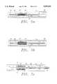
- FIG. 3ais a partial side elevational view of an alternative embodiment of the stent of the present invention.
- FIG. 3bis a partial side elevational view show an alternative bend configuration useable in forming the stents of the present invention.
- FIG. 4ais an enlarged perspective view of the distal portion of a balloon catheter having the stent device operatively positioned thereupon;
- FIG. 4bis an enlarged perspective view of a retaining sheath utilized to maintain the stent device in position upon the balloon of the balloon catheter;
- FIG. 4cis an enlarged perspective view of the distal portion of a balloon catheter wherein the balloon is inflated to tear the retaining sheaths;
- FIG. 5ashows a first stage of a preferred method for delivering a stent of the present invention using the stent delivery apparatus of the present invention.
- FIG. 5bshows a second stage of a preferred method for delivering a stent of the present invention using the stent delivery apparatus of the present invention.
- FIG. 5cshows a third stage of a preferred method for delivering a stent of the present invention using the stent delivery apparatus of the present invention.
- a stent device 10constructed in accordance with the preferred embodiment of the present invention as operatively positioned within an anatomical passageway 12 such as a blood vessel.
- anatomical passageway 12such as a blood vessel.
- the stent 10may be utilized to reinforce or dilate numerous types of anatomical passageways, including blood vessels, urogenital passageways and bioducts.
- the stent 10is typically inserted into a blood vessel to dilate areas of the vessel which have become occluded by atherosclerotic plaque or constricted by an adjacent tumor.
- the stent 10is formed from an elongate wire member 14 defining a first end 16 and a second end 18.
- the wire member 14is preferrably fabricated from a titanium alloy, though other biocompatible materials of similar resiliency may be utilized as an alternative.
- the wire member 14is manipulated in a manner defining a multiplicity of radius bends 20 which are formed at spaced locations along the length thereof.
- Each of the bends 20preferrably forms an angle of approximately 180° so as to define multiple straight segments 22 of the wire member 14 between the bends 20.
- the straight segments 22 defined between the radius bends 20are disposed in generally parallel, convoluted relation to one another.
- the wire member 14defines a multiplicity of convolutions 24, each of which are formed by an adjacent pair of straight segments 22 and a single radius bend 20.
- the wire member 14 shown in FIG. 2bincludes eight (8) convolutions formed therein, while the wire member 14 shown in FIG. 2c includes ten (10) convolutions formed therein.
- the radius bends 20are formed in the wire member 14 via the engagement of the wire member 14 to a suitable mandrel, though it will be recognized that other formation techniques may also be utilized.
- the first end 16 of the wire member 14terminates at approximately the mid-point of the adjacent straight segment 22.
- the second end 18 of the wire member 14terminates at approximately the midpoint of the straight segment 22 adjacent thereto.
- the wire member 14possesses sufficient flexibility so as to allow the first end 16 to be rolled toward the second end 18 in the manner shown in FIG. 2c subsequent to the formation of the convolutions 24 therewithin.
- the convoluted wire member 14is rolled so as to position the first end 16 thereof into coaxial alignment with the second end 18. Thereafter, the first end 16 is fused to the second end 18. Such fusion is preferrably facilitated via a welding process, though other attachment methods may be utilized.
- the straight segments 22 of the wire member 14assume a generally cylindrical array about a longitudinal axis A and define therewithin an internal flow channel 26 having a first internal diameter D 1 .
- the stent 10is compressed or folded from its "operative" configuration having inner diameter D 1 to its "compact” configuration having an outer diameter (or other cross-sectional dimension) D 2 , prior to being delivered to its intended placement site within the anatomical passageway 12.
- the stent device 10When in its desired placement location, the stent device 10 is allowed to self-expand from its "compact” configuration to its "operative” configuration, thereby causing the stent 10 to radially engage the inner wall 13 of the anatomical passageway 12.
- Such placement of the stent 10serves to maintain the patency of the anatomical passageway 12 or to otherwise hold the stent (along with any accompanying apparatus such as an endovascular graft) in fixed position within the passageway 12.
- the manner in which the stent 10 is delivered and released at its intended implantation siteis discussed in more detail below.
- the operatively configured stent 10is sized such that when the flow channel 26 is expanded to its full internal diameter D 1 the straight segments 22 are substantially parallel (i.e., preferably no more than 5° out of parallel) to one another.
- the relationship of the straight segments 22 to the longitudinal axis A of flow through the passageway 12is determinative of the amount of flow disruption or turbulence which will result from placement of the stent 10 within the passageway 12.
- the substantially parallel disposition of the straight segments 22 relative to the axis of flow Aresults in a minimization of turbulence-induced thromboembolic complications when the stent is placed within a blood vessel.
- the size of the stent 10is a function of the number of convolutions 24 formed therein and total length of the wire member 14.
- the number of convolutions 24 formed within the stent 10is selected based on the internal diameter of the anatomical passageway 12 into which the stent 10 is to be operatively positioned.
- the number of convolutions 24, and the radius and/or configuration of the radius bends 20may be varied, depending on the intended size and function of the stent 10.
- the stentcomprises a relatively large number of straight segments 22, having relatively small radius bends 20 formed therebetween.
- the embodiment shown in FIG. 3autilizes fewer straight segments 22 and incorporates larger radius bends 20a, as shown.
- the linear or squared bends 20bas shown in FIG. 3b, may be utilized in place of the generally rounded radius bends 20, 20a shown in the preferred embodiment.
- the deployment catheter 30generally comprises an elongate catheter body 32 defining an open distal end 34 and a hollow lumen 36 extending longitudinally therethrough.
- an inflatable balloon 38Positioned upon the outer surface of the catheter body 32 adjacent the distal end 34 thereof is an inflatable balloon 38 and a set of tearable retaining sheaths 40.
- the balloon 38may comprise a cylindrical elastic member, the opposed ends of which are attached to the outer surface of the catheter body 32, typically via a heat sealing process.
- the balloonis inflatable to a diameter which causes the retaining sheaths 40 to tear, thereby releasing the stent 10, and permitting the stent to self-expand in situ.
- the catheter body 32includes a balloon inflation lumen which is in fluid communication with the inflation space defined between the balloon 38 and the outer surface of the catheter body 32 for selectively inflating and deflating the balloon 38.
- the catheter body 32may be formed with a closed distal end 34, and that the lumen 36 may function as the balloon inflation lumen.
- the inflatable balloon 38may comprise an integral portion of the catheter body sized and located so as to effect the intended tearing of the retaining sheaths 32, when inflated.
- the stent 10is extended over the catheter body 32 such that the deflated balloon 38 is centrally disposed within the flow channel 26.
- the stent 10is compresses or folded to its compact configuration (D 2 ) and the retaining sheaths 40 are mounted around the ends of the compact stent 10 to hold the stent 10, in its compact configuration, on the outer surface of the deflated balloon 38, as shown in FIG. 4a.
- each of the retaining sheaths 40has a generally cylindrical configuration and is provided with sets of perforations 42 which extend longitudinally from one end of the sheath 40 to the approximate mid-point thereof.
- the retaining sheaths 40are interfaced to the stent 10 and dilation balloon 38 such that the portions thereof including the perforations 42 disposed therein are extended over (i.e., overlap) the ends of the stent 10, with the non-perforated portions being directly engaged to the outer surface of the balloon 38.
- the retaining sheaths 40are preferrably formed of plastic which is weakened or perforated such that the retaining sheaths 40 will tear away from the ends of the stent 10 as the balloon 38 is inflated.
- the retaining sheaths 40may be formed of any suitable material.
- the retaining sheaths 40may be formed of heat shrinkable plastic material and such retaining sheaths 40 may be heat shrunk into place on the ends of the stent 10.
- the retaining sheaths 40may be formed of soft pliable elastomeric material such as silicone polyurethane or latex, although such materials may not be heat shrinkable.
- the elastomeric materialsmay be elastically expanded and allowed to elastically contract into place on the ends of the stent 10 or, alternatively, may be initially swelled by solvent application and subsequently allowed to post-contract about the outer surface of the catheter body and over the ends of the stent 10, as shown.
- the retaining sheaths 40are adapted to tear under pressure as the balloon 38 is inflated. Such tearing of the sheaths 40 release the stent 10, thus allowing the stent to self-expand from its compact configuration (D 2 ) to its operation configuration (D 1 ).
- the locations of the perforations 42 within the retaining sheaths 40causes only those portions of the sheaths 40 which are extended over the opposed ends of the stent 10 to be torn by the expansion of the balloon 38, thus preventing the remaining portions of the sheaths 40 from becoming torn away from attachment to the balloon 38 and or catheter body 32.
- Such residual attachment of the torn sheaths 40ensures that the torn sheaths 40 may subsequently be extracted and removed along with the deployment catheter 30.
- the torn ends of the retaining sheaths 40are not captured between the expanded stent 10 and the inner wall 13.
- the catheter body 32, balloon 38 and torn retaining sheaths 40may easily be pulled proximally through and out of the internal flow channel 26 of the stent 10, thus leaving the stent 10 operatively positioned at the treatment site within the anatomical passageway 12.
- the balloon 38need only inflate to a diameter which is sufficient to cause tearing or breaking of the retaining sheaths 40.
- the maximal inflation limit of the balloonmay be such that the outer diameter of the balloon tears the retaining sheaths 40 but does not fully occlude or fully block the lumen of the anatomical passageway (e.g., blood vessel) within which the stent 10 is being placed.
- the self-expandability of the stentwill cause the stent to expand to its full operative configuration (D 1 ) despite the fact that the maximal diameter of the inflated balloon 38 may be substantially less than the internal diameter D 1 of the operatively configured stent.
- the stent 10 of the present inventionis utilized by initially positioning the stent 10 upon the balloon 38 of the deployment catheter 30 and thereafter compressing and folding the stent to its compact configuration.
- the ends of the stent 10are then wrapped by the retaining sheaths 40 in the aforementioned manner to hold the stent 10 in its compact configuration upon the balloon 38.
- the deployment catheter 30, having the compacted stent 10 positioned thereonis inserted and transluminally advanced through the anatomical passageway 12 to its desired placement site, such as the location of an existing or previously balloon-dilated atherosclerotic plaque occlusion 44.
- the balloon 38is inflated via the inflation lumen, thus causing the perforations 42 of the sheaths 40 to tear (FIG. 5b), and thus releasing the stent 10.
- the stentthen self-expands to its operative configuration (D 1 ).
- Such expansion of the stent 10causes the stent 10 to radially engage the inner wall 13 of the anatomical passageway 12 and to exert sufficient radial outward pressure thereon to perform the required function of the stent (e.g., to maintain patency of the passageway 12).
- the balloon 38is then deflated, and the deployment catheter 30 is removed (FIG. 5c) from the anatomical passageway 12, thus allowing the stent 10 to remain operatively positioned at the desired placement site therewithin.
- the preferred method of the present inventionmay be carried out percutaneously, or by way an open surgical procedure.
- the deployment catheter 30 having the stent 10 positioned thereuponis initially passed through an incision which provides access into the anatomical passageway 12.
- the deployment catheter 30 having the stent 10 positioned thereuponis passed percutaneously through a tubular introducer and subsequently transluminally advanced into the anatomical passageway 12 to the occlusion 44 therewithin.
- the anatomical passageway 12 in which the stent 10 is utilizedcomprises a blood vessel
- the treatment sitetypically is an area of atherosclerotic plaque occlusion or a compressed area of the blood vessel which has been affected by a tumor or other pathology.
- the present methodis typically carried out subsequent to a balloon dilation angioplasty, or any other type of angioplasty procedure at the treatment site.
Landscapes
- Health & Medical Sciences (AREA)
- Engineering & Computer Science (AREA)
- Biomedical Technology (AREA)
- Cardiology (AREA)
- Oral & Maxillofacial Surgery (AREA)
- Transplantation (AREA)
- Heart & Thoracic Surgery (AREA)
- Vascular Medicine (AREA)
- Life Sciences & Earth Sciences (AREA)
- Animal Behavior & Ethology (AREA)
- General Health & Medical Sciences (AREA)
- Public Health (AREA)
- Veterinary Medicine (AREA)
- Media Introduction/Drainage Providing Device (AREA)
Abstract
Description
Claims (30)
Priority Applications (4)
| Application Number | Priority Date | Filing Date | Title |
|---|---|---|---|
| US08/415,846US5549635A (en) | 1994-01-24 | 1995-04-03 | Non-deformable self-expanding parallel flow endovascular stent and deployment apparatus therefore |
| PCT/US1996/004644WO1996031249A1 (en) | 1995-04-03 | 1996-04-03 | Non-deformable self-expanding parallel flow endovascular stent and deployment apparatus therefor |
| EP96912563AEP0819015A4 (en) | 1995-04-03 | 1996-04-03 | Non-deformable self-expanding parallel flow endovascular stent and deployment apparatus therefor |
| JP8530471AJPH11503341A (en) | 1995-04-03 | 1996-04-03 | Non-deformable self-expanding intravascular stent for parallel flow formation and insertion device |
Applications Claiming Priority (2)
| Application Number | Priority Date | Filing Date | Title |
|---|---|---|---|
| US08/185,549US5403341A (en) | 1994-01-24 | 1994-01-24 | Parallel flow endovascular stent and deployment apparatus therefore |
| US08/415,846US5549635A (en) | 1994-01-24 | 1995-04-03 | Non-deformable self-expanding parallel flow endovascular stent and deployment apparatus therefore |
Related Parent Applications (1)
| Application Number | Title | Priority Date | Filing Date |
|---|---|---|---|
| US08/185,549Continuation-In-PartUS5403341A (en) | 1994-01-24 | 1994-01-24 | Parallel flow endovascular stent and deployment apparatus therefore |
Publications (1)
| Publication Number | Publication Date |
|---|---|
| US5549635Atrue US5549635A (en) | 1996-08-27 |
Family
ID=23647448
Family Applications (1)
| Application Number | Title | Priority Date | Filing Date |
|---|---|---|---|
| US08/415,846Expired - LifetimeUS5549635A (en) | 1994-01-24 | 1995-04-03 | Non-deformable self-expanding parallel flow endovascular stent and deployment apparatus therefore |
Country Status (4)
| Country | Link |
|---|---|
| US (1) | US5549635A (en) |
| EP (1) | EP0819015A4 (en) |
| JP (1) | JPH11503341A (en) |
| WO (1) | WO1996031249A1 (en) |
Cited By (150)
| Publication number | Priority date | Publication date | Assignee | Title |
|---|---|---|---|---|
| US5735871A (en)* | 1994-12-09 | 1998-04-07 | Sgro; Jean-Claude | Self-expanding endoprosthesis |
| US5776181A (en)* | 1995-07-25 | 1998-07-07 | Medstent Inc. | Expandable stent |
| US5843119A (en)* | 1996-10-23 | 1998-12-01 | United States Surgical Corporation | Apparatus and method for dilatation of a body lumen and delivery of a prothesis therein |
| US5873906A (en) | 1994-09-08 | 1999-02-23 | Gore Enterprise Holdings, Inc. | Procedures for introducing stents and stent-grafts |
| US5876432A (en) | 1994-04-01 | 1999-03-02 | Gore Enterprise Holdings, Inc. | Self-expandable helical intravascular stent and stent-graft |
| EP0897730A3 (en)* | 1997-08-11 | 1999-03-24 | Advanced Cardiovascular Systems, Inc. | Retainer for a stent-carrying balloon catheter |
| US5891190A (en)* | 1989-08-24 | 1999-04-06 | Boneau; Michael D. | Endovascular support device and method |
| US5925061A (en) | 1997-01-13 | 1999-07-20 | Gore Enterprise Holdings, Inc. | Low profile vascular stent |
| US6001123A (en) | 1994-04-01 | 1999-12-14 | Gore Enterprise Holdings Inc. | Folding self-expandable intravascular stent-graft |
| US6036725A (en)* | 1998-06-10 | 2000-03-14 | General Science And Technology | Expandable endovascular support device |
| US6042605A (en) | 1995-12-14 | 2000-03-28 | Gore Enterprose Holdings, Inc. | Kink resistant stent-graft |
| EP1034752A1 (en)* | 1999-03-11 | 2000-09-13 | Medtronic, Inc. | Method of stent retention to a delivery catheter balloon - braided retainers |
| WO2000078249A1 (en)* | 1999-06-17 | 2000-12-28 | Scimed Life Systems, Inc. | Stent securement by balloon modification |
| US6168616B1 (en) | 1997-06-02 | 2001-01-02 | Global Vascular Concepts | Manually expandable stent |
| US6191365B1 (en) | 1997-05-02 | 2001-02-20 | General Science And Technology Corp | Medical devices incorporating at least one element made from a plurality of twisted and drawn wires |
| US6221096B1 (en)* | 1997-06-09 | 2001-04-24 | Kanto Special Steel Works, Ltd. | Intravascular stent |
| US6235051B1 (en)* | 1997-12-16 | 2001-05-22 | Timothy P. Murphy | Method of stent-graft system delivery |
| US6261318B1 (en) | 1995-07-25 | 2001-07-17 | Medstent Inc. | Expandable stent |
| US6273908B1 (en) | 1997-10-24 | 2001-08-14 | Robert Ndondo-Lay | Stents |
| US6289568B1 (en) | 1998-11-16 | 2001-09-18 | Cordis Corporation | Method for making a balloon catheter stent deployment system |
| US6293959B1 (en) | 1998-11-16 | 2001-09-25 | Cordis Corporation | Balloon catheter and stent delivery system having enhanced stent retention and method |
| US6309411B1 (en) | 1994-10-19 | 2001-10-30 | Medtronic Ave, Inc. | Method and apparatus to prevent stent migration |
| WO2001080780A1 (en)* | 2000-04-20 | 2001-11-01 | Scimed Life Systems, Inc. | Fully sheathed balloon expandable stent delivery system |
| US6331188B1 (en) | 1994-08-31 | 2001-12-18 | Gore Enterprise Holdings, Inc. | Exterior supported self-expanding stent-graft |
| WO2001097715A1 (en)* | 2000-06-22 | 2001-12-27 | Jan Otto Solem | Delivery system |
| US6344053B1 (en)* | 1993-12-22 | 2002-02-05 | Medtronic Ave, Inc. | Endovascular support device and method |
| US6352553B1 (en) | 1995-12-14 | 2002-03-05 | Gore Enterprise Holdings, Inc. | Stent-graft deployment apparatus and method |
| US6352561B1 (en) | 1996-12-23 | 2002-03-05 | W. L. Gore & Associates | Implant deployment apparatus |
| US20020038143A1 (en)* | 1995-03-10 | 2002-03-28 | Mccrea Brendan J. | Diametrically adaptable encapsulated stent and methods for deployment thereof |
| US6464718B1 (en) | 1998-11-16 | 2002-10-15 | Cordis Corporation | Balloon catheter for stent delivery having microchannels and method |
| WO2003020173A1 (en)* | 2001-09-04 | 2003-03-13 | Graeme Cocks | A stent |
| US20030055482A1 (en)* | 2001-09-19 | 2003-03-20 | Jomed Gmbh | Cold-molding process for loading a stent onto a stent delivery system |
| US6547813B2 (en) | 2001-03-23 | 2003-04-15 | Medtronic Ave, Inc. | Stent delivery catheter with folded sleeve and method of making same |
| US6551350B1 (en) | 1996-12-23 | 2003-04-22 | Gore Enterprise Holdings, Inc. | Kink resistant bifurcated prosthesis |
| US6589274B2 (en) | 2001-03-23 | 2003-07-08 | Medtronic Ave, Inc. | Stent delivery catheter and method of making same |
| US20030130683A1 (en)* | 2001-12-03 | 2003-07-10 | Xtent, Inc., | Apparatus and methods for delivering coiled prostheses |
| WO2003065936A1 (en)* | 2002-02-04 | 2003-08-14 | Boston Scientific Limited | Medical devices |
| US20030181810A1 (en)* | 2002-03-25 | 2003-09-25 | Murphy Kieran P. | Kit for image guided surgical procedures |
| US6629992B2 (en)* | 2000-08-04 | 2003-10-07 | Advanced Cardiovascular Systems, Inc. | Sheath for self-expanding stent |
| US6638293B1 (en) | 1996-02-02 | 2003-10-28 | Transvascular, Inc. | Methods and apparatus for blocking flow through blood vessels |
| US20030204248A1 (en)* | 2002-03-25 | 2003-10-30 | Murphy Kieran P. | Device viewable under an imaging beam |
| US20030212410A1 (en)* | 2002-05-08 | 2003-11-13 | Stenzel Eric B. | Method and device for providing full protection to a stent |
| US20040006344A1 (en)* | 2002-07-02 | 2004-01-08 | Nguyen Thanh Van | Expandable percutaneous sheath |
| US20040098076A1 (en)* | 2001-05-18 | 2004-05-20 | Giovanni Rolando | Variable structure element for implant devices, corresponding implant device and method of manufacturing |
| US20040138731A1 (en)* | 2001-02-16 | 2004-07-15 | Johnson Eric G. | Method of balloon catheter stent delivery system with ridges |
| US20040153138A1 (en)* | 2002-03-25 | 2004-08-05 | Kieran Murphy | Device viewable under an imaging beam |
| US20040181273A1 (en)* | 2003-03-10 | 2004-09-16 | Evan Brasington | Dilator with expandable member |
| US6805706B2 (en) | 2002-08-15 | 2004-10-19 | Gmp Cardiac Care, Inc. | Stent-graft with rails |
| US20050017540A1 (en)* | 2003-07-22 | 2005-01-27 | Leigh Arthur Donald | Caravan |
| US20050033405A1 (en)* | 2002-08-15 | 2005-02-10 | Gmp/Cardiac Care, Inc. | Rail stent-graft for repairing abdominal aortic aneurysm |
| US20050049672A1 (en)* | 2003-03-24 | 2005-03-03 | Murphy Kieran P. | Stent delivery system and method using a balloon for a self-expandable stent |
| US20050070821A1 (en)* | 2003-07-31 | 2005-03-31 | Deal Stephen E. | System and method for introducing a prosthesis |
| US20050154443A1 (en)* | 2004-01-09 | 2005-07-14 | Rubicon Medical, Inc. | Stent delivery device |
| US20050283222A1 (en)* | 2000-09-18 | 2005-12-22 | Endotex Interventional Systems, Inc. | Apparatus for delivering endoluminal prostheses and methods of making and using them |
| US20060015171A1 (en)* | 2004-07-16 | 2006-01-19 | Armstrong Joseph R | Deployment system for intraluminal devices |
| US20060106455A1 (en)* | 2004-11-12 | 2006-05-18 | Icon Interventional Systems, Inc. | Ostial stent |
| US20060229714A1 (en)* | 1995-03-10 | 2006-10-12 | Sylvie Lombardi | Covered stent with encapsulated ends |
| US20060235501A1 (en)* | 2003-05-23 | 2006-10-19 | Keiji Igaki | Stent supplying device |
| US7147655B2 (en) | 2001-03-29 | 2006-12-12 | Xtent, Inc. | Balloon catheter for multiple adjustable stent deployment |
| US20070016280A1 (en)* | 2005-07-14 | 2007-01-18 | Cappella, Inc. | Delivery System And Method Of Use For Deployment Of Self-Expandable Vascular Device |
| US20070100424A1 (en)* | 2001-12-03 | 2007-05-03 | Xtent, Inc. | Apparatus and methods for delivery of multiple distributed stents |
| US20070233232A1 (en)* | 2006-03-31 | 2007-10-04 | St Germain Jon | Stent and system and method for deploying a stent |
| US7294146B2 (en) | 2001-12-03 | 2007-11-13 | Xtent, Inc. | Apparatus and methods for delivery of variable length stents |
| US7300456B2 (en) | 2004-06-28 | 2007-11-27 | Xtent, Inc. | Custom-length self-expanding stent delivery systems with stent bumpers |
| US7309350B2 (en) | 2001-12-03 | 2007-12-18 | Xtent, Inc. | Apparatus and methods for deployment of vascular prostheses |
| US7320702B2 (en) | 2005-06-08 | 2008-01-22 | Xtent, Inc. | Apparatus and methods for deployment of multiple custom-length prostheses (III) |
| US7326236B2 (en) | 2003-12-23 | 2008-02-05 | Xtent, Inc. | Devices and methods for controlling and indicating the length of an interventional element |
| US7351255B2 (en) | 2001-12-03 | 2008-04-01 | Xtent, Inc. | Stent delivery apparatus and method |
| US7357812B2 (en) | 2001-12-03 | 2008-04-15 | Xtent, Inc. | Apparatus and methods for delivery of braided prostheses |
| US7402168B2 (en) | 2005-04-11 | 2008-07-22 | Xtent, Inc. | Custom-length stent delivery system with independently operable expansion elements |
| US20080249464A1 (en)* | 2007-04-05 | 2008-10-09 | Boston Scientific Scimed, Inc. | Catheter Having Internal Mechanisms to Encourage Balloon Re-folding |
| US20080269868A1 (en)* | 2007-04-25 | 2008-10-30 | Abbott Cardiovascular Systems Inc. | Stent delivery catheter system and method of implanting a self-expanding stent with embolic protection |
| US20080319388A1 (en)* | 2007-06-21 | 2008-12-25 | David Slattery | Device delivery system with balloon-relative sheath positioning |
| US20090036966A1 (en)* | 2007-08-01 | 2009-02-05 | O'connor Therese | Device Delivery System With Two Stage Withdrawal |
| US7553324B2 (en) | 2003-10-14 | 2009-06-30 | Xtent, Inc. | Fixed stent delivery devices and methods |
| US20090187210A1 (en)* | 2007-12-21 | 2009-07-23 | Abbott Laboratories | Vena cava filter having hourglass shape |
| US7572270B2 (en) | 2001-02-16 | 2009-08-11 | Cordis Corporation | Balloon catheter stent delivery system with ridges |
| US20090287292A1 (en)* | 2008-05-13 | 2009-11-19 | Becking Frank P | Braid Implant Delivery Systems |
| US20100131038A1 (en)* | 2006-07-21 | 2010-05-27 | Zoran Milijasevic | Stent assembly |
| US7892203B2 (en) | 2004-09-09 | 2011-02-22 | Onset Medical Corporation | Expandable transluminal sheath |
| US7892273B2 (en) | 2001-12-03 | 2011-02-22 | Xtent, Inc. | Custom length stent apparatus |
| US7918881B2 (en) | 2003-06-09 | 2011-04-05 | Xtent, Inc. | Stent deployment systems and methods |
| US7922755B2 (en) | 2001-12-03 | 2011-04-12 | Xtent, Inc. | Apparatus and methods for delivery of multiple distributed stents |
| US20110106234A1 (en)* | 2009-10-30 | 2011-05-05 | Axel Grandt | Interluminal medical treatment devices and methods |
| US7938851B2 (en) | 2005-06-08 | 2011-05-10 | Xtent, Inc. | Devices and methods for operating and controlling interventional apparatus |
| WO2011123852A1 (en) | 2010-04-02 | 2011-10-06 | Cappella, Inc. | Systems and methods for delivering a stent to a body lumen |
| US8034100B2 (en) | 1999-03-11 | 2011-10-11 | Endologix, Inc. | Graft deployment system |
| US8080048B2 (en) | 2001-12-03 | 2011-12-20 | Xtent, Inc. | Stent delivery for bifurcated vessels |
| US8083788B2 (en) | 2001-12-03 | 2011-12-27 | Xtent, Inc. | Apparatus and methods for positioning prostheses for deployment from a catheter |
| US20120071912A1 (en)* | 2010-09-17 | 2012-03-22 | Campbell Carey V | Expandable medical devices |
| US8167925B2 (en) | 1999-03-11 | 2012-05-01 | Endologix, Inc. | Single puncture bifurcation graft deployment system |
| US8196279B2 (en) | 2008-02-27 | 2012-06-12 | C. R. Bard, Inc. | Stent-graft covering process |
| US8216295B2 (en) | 2008-07-01 | 2012-07-10 | Endologix, Inc. | Catheter system and methods of using same |
| US8236040B2 (en) | 2008-04-11 | 2012-08-07 | Endologix, Inc. | Bifurcated graft deployment systems and methods |
| US8257427B2 (en) | 2001-09-11 | 2012-09-04 | J.W. Medical Systems, Ltd. | Expandable stent |
| US8282680B2 (en) | 2003-01-17 | 2012-10-09 | J. W. Medical Systems Ltd. | Multiple independent nested stent structures and methods for their preparation and deployment |
| US8317859B2 (en) | 2004-06-28 | 2012-11-27 | J.W. Medical Systems Ltd. | Devices and methods for controlling expandable prostheses during deployment |
| US8337650B2 (en) | 1995-03-10 | 2012-12-25 | Bard Peripheral Vascular, Inc. | Methods for making a supported graft |
| US8460358B2 (en) | 2004-03-30 | 2013-06-11 | J.W. Medical Systems, Ltd. | Rapid exchange interventional devices and methods |
| US8486132B2 (en) | 2007-03-22 | 2013-07-16 | J.W. Medical Systems Ltd. | Devices and methods for controlling expandable prostheses during deployment |
| US8591565B2 (en) | 2008-12-12 | 2013-11-26 | Abbott Laboratories Vascular Enterprises Limited | Process for loading a stent onto a stent delivery system |
| US8597277B2 (en) | 2004-09-09 | 2013-12-03 | Onset Medical Corporation | Expandable transluminal sheath |
| US8617337B2 (en) | 1999-02-02 | 2013-12-31 | Bard Peripheral Vascular, Inc. | Partial encapsulation of stents |
| US8636760B2 (en) | 2009-04-20 | 2014-01-28 | Covidien Lp | System and method for delivering and deploying an occluding device within a vessel |
| US8652198B2 (en) | 2006-03-20 | 2014-02-18 | J.W. Medical Systems Ltd. | Apparatus and methods for deployment of linked prosthetic segments |
| US8696701B2 (en) | 2008-04-21 | 2014-04-15 | Covidien Lp | Braid-ball embolic devices |
| US8769796B2 (en) | 2008-09-25 | 2014-07-08 | Advanced Bifurcation Systems, Inc. | Selective stent crimping |
| US8795347B2 (en) | 2008-09-25 | 2014-08-05 | Advanced Bifurcation Systems, Inc. | Methods and systems for treating a bifurcation with provisional side branch stenting |
| US8808347B2 (en) | 2008-09-25 | 2014-08-19 | Advanced Bifurcation Systems, Inc. | Stent alignment during treatment of a bifurcation |
| US8821562B2 (en) | 2008-09-25 | 2014-09-02 | Advanced Bifurcation Systems, Inc. | Partially crimped stent |
| CN104069583A (en)* | 2014-07-23 | 2014-10-01 | 王丽华 | Heart and blood vessel expanding device |
| US8925177B2 (en) | 2006-06-19 | 2015-01-06 | Abbott Cardiovascular Systems Inc. | Methods for improving stent retention on a balloon catheter |
| US8926681B2 (en) | 2010-01-28 | 2015-01-06 | Covidien Lp | Vascular remodeling device |
| US8945202B2 (en) | 2009-04-28 | 2015-02-03 | Endologix, Inc. | Fenestrated prosthesis |
| US8979917B2 (en) | 2008-09-25 | 2015-03-17 | Advanced Bifurcation Systems, Inc. | System and methods for treating a bifurcation |
| US8980297B2 (en) | 2007-02-20 | 2015-03-17 | J.W. Medical Systems Ltd. | Thermo-mechanically controlled implants and methods of use |
| US9060886B2 (en) | 2011-09-29 | 2015-06-23 | Covidien Lp | Vascular remodeling device |
| US9089332B2 (en) | 2011-03-25 | 2015-07-28 | Covidien Lp | Vascular remodeling device |
| US9095342B2 (en) | 2009-11-09 | 2015-08-04 | Covidien Lp | Braid ball embolic device features |
| US9095343B2 (en) | 2005-05-25 | 2015-08-04 | Covidien Lp | System and method for delivering and deploying an occluding device within a vessel |
| US9101503B2 (en) | 2008-03-06 | 2015-08-11 | J.W. Medical Systems Ltd. | Apparatus having variable strut length and methods of use |
| US9155647B2 (en) | 2012-07-18 | 2015-10-13 | Covidien Lp | Methods and apparatus for luminal stenting |
| US9179918B2 (en) | 2008-07-22 | 2015-11-10 | Covidien Lp | Vascular remodeling device |
| US9204983B2 (en) | 2005-05-25 | 2015-12-08 | Covidien Lp | System and method for delivering and deploying an occluding device within a vessel |
| US9241735B2 (en) | 2003-12-05 | 2016-01-26 | Onset Medical Corporation | Expandable percutaneous sheath |
| US9254210B2 (en) | 2011-02-08 | 2016-02-09 | Advanced Bifurcation Systems, Inc. | Multi-stent and multi-balloon apparatus for treating bifurcations and methods of use |
| US9295571B2 (en) | 2013-01-17 | 2016-03-29 | Covidien Lp | Methods and apparatus for luminal stenting |
| US9314248B2 (en) | 2012-11-06 | 2016-04-19 | Covidien Lp | Multi-pivot thrombectomy device |
| US9364356B2 (en) | 2011-02-08 | 2016-06-14 | Advanced Bifurcation System, Inc. | System and methods for treating a bifurcation with a fully crimped stent |
| US9375203B2 (en) | 2002-03-25 | 2016-06-28 | Kieran Murphy Llc | Biopsy needle |
| US9393022B2 (en) | 2011-02-11 | 2016-07-19 | Covidien Lp | Two-stage deployment aneurysm embolization devices |
| US9463105B2 (en) | 2013-03-14 | 2016-10-11 | Covidien Lp | Methods and apparatus for luminal stenting |
| US9468442B2 (en) | 2010-01-28 | 2016-10-18 | Covidien Lp | Vascular remodeling device |
| US9549835B2 (en) | 2011-03-01 | 2017-01-24 | Endologix, Inc. | Catheter system and methods of using same |
| US9737424B2 (en) | 2008-09-25 | 2017-08-22 | Advanced Bifurcation Systems, Inc. | Partially crimped stent |
| US10245166B2 (en) | 2008-02-22 | 2019-04-02 | Endologix, Inc. | Apparatus and method of placement of a graft or graft system |
| US10478194B2 (en) | 2015-09-23 | 2019-11-19 | Covidien Lp | Occlusive devices |
| WO2020022915A1 (en) | 2018-07-24 | 2020-01-30 | American Heart Of Poland S.A. | Delivery system for implants used in structural heart diseases by a minimally invasive method |
| US10575973B2 (en) | 2018-04-11 | 2020-03-03 | Abbott Cardiovascular Systems Inc. | Intravascular stent having high fatigue performance |
| US10736758B2 (en) | 2013-03-15 | 2020-08-11 | Covidien | Occlusive device |
| CN113081390A (en)* | 2021-04-12 | 2021-07-09 | 苏州茵络医疗器械有限公司 | Bare crown stent releasing assembly for ascending aorta covered stent conveying system |
| US11129737B2 (en) | 2015-06-30 | 2021-09-28 | Endologix Llc | Locking assembly for coupling guidewire to delivery system |
| US11298252B2 (en) | 2008-09-25 | 2022-04-12 | Advanced Bifurcation Systems Inc. | Stent alignment during treatment of a bifurcation |
| US11406518B2 (en) | 2010-11-02 | 2022-08-09 | Endologix Llc | Apparatus and method of placement of a graft or graft system |
| US12042617B2 (en) | 2018-02-13 | 2024-07-23 | Kieran P. Murphy | Delivery system for delivering a drug depot to a target site under image guidance and methods and uses of same |
| US12076258B2 (en) | 2008-09-25 | 2024-09-03 | Advanced Bifurcation Systems Inc. | Selective stent crimping |
| US12102527B2 (en) | 2018-07-24 | 2024-10-01 | Innovations For Heart And Vessels Sp. Z O.O. | Biological low profile, balloon expandable prosthetic heart valve, particularly aortic, for transcatheter implantation and the method of its manufacturing |
| US12156808B2 (en) | 2018-07-24 | 2024-12-03 | Innovations For Heart And Vessels Sp. Z O.O. | Method of forming prefabricated units used in production of systems of prosthetic aortic valve transcatheter implantation and prosthetic aortic valve prefabricated unit |
| US12263082B2 (en) | 2018-07-24 | 2025-04-01 | Innovations For Heart And Vessels Sp. Z O.O. | Low profile balloon expandable artificial prosthetic heart valve, particularly aortic, for transcatheter implantation |
| US12324756B2 (en) | 2008-09-25 | 2025-06-10 | Advanced Bifurcation Systems Inc. | System and methods for treating a bifurcation |
Families Citing this family (10)
| Publication number | Priority date | Publication date | Assignee | Title |
|---|---|---|---|---|
| US6533805B1 (en) | 1996-04-01 | 2003-03-18 | General Surgical Innovations, Inc. | Prosthesis and method for deployment within a body lumen |
| US5810871A (en)* | 1997-04-29 | 1998-09-22 | Medtronic, Inc. | Stent delivery system |
| US6174316B1 (en) | 1998-05-28 | 2001-01-16 | Medtronic, Inc. | Stent delivery system |
| US6964676B1 (en)* | 2000-04-14 | 2005-11-15 | Scimed Life Systems, Inc. | Stent securement system |
| US6899727B2 (en)* | 2001-01-22 | 2005-05-31 | Gore Enterprise Holdings, Inc. | Deployment system for intraluminal devices |
| US6623451B2 (en)* | 2001-05-01 | 2003-09-23 | Scimed Life Systems, Inc. | Folding spring for a catheter balloon |
| EP1679095A4 (en)* | 2003-10-15 | 2011-08-03 | Igaki Iryo Sekkei Kk | Vessel stent feeder |
| DE102006040301A1 (en)* | 2005-12-06 | 2008-03-06 | Düring, Klaus, Dr. | Device for splinting a cavity, organ path and / or vessel |
| EP2170230A1 (en)* | 2007-06-21 | 2010-04-07 | Cappella Inc. | Medical device delivery system with sheath having balloon-relative position |
| WO2015157181A1 (en)* | 2014-04-08 | 2015-10-15 | Stryker Corporation | Implant delivery system |
Citations (13)
| Publication number | Priority date | Publication date | Assignee | Title |
|---|---|---|---|---|
| US4580568A (en)* | 1984-10-01 | 1986-04-08 | Cook, Incorporated | Percutaneous endovascular stent and method for insertion thereof |
| US4733665A (en)* | 1985-11-07 | 1988-03-29 | Expandable Grafts Partnership | Expandable intraluminal graft, and method and apparatus for implanting an expandable intraluminal graft |
| US4830003A (en)* | 1988-06-17 | 1989-05-16 | Wolff Rodney G | Compressive stent and delivery system |
| US4922905A (en)* | 1985-11-30 | 1990-05-08 | Strecker Ernst P | Dilatation catheter |
| US4950227A (en)* | 1988-11-07 | 1990-08-21 | Boston Scientific Corporation | Stent delivery system |
| US5035706A (en)* | 1989-10-17 | 1991-07-30 | Cook Incorporated | Percutaneous stent and method for retrieval thereof |
| US5041126A (en)* | 1987-03-13 | 1991-08-20 | Cook Incorporated | Endovascular stent and delivery system |
| US5108416A (en)* | 1990-02-13 | 1992-04-28 | C. R. Bard, Inc. | Stent introducer system |
| US5135536A (en)* | 1991-02-05 | 1992-08-04 | Cordis Corporation | Endovascular stent and method |
| US5161547A (en)* | 1990-11-28 | 1992-11-10 | Numed, Inc. | Method of forming an intravascular radially expandable stent |
| US5282824A (en)* | 1990-10-09 | 1994-02-01 | Cook, Incorporated | Percutaneous stent assembly |
| US5292331A (en)* | 1989-08-24 | 1994-03-08 | Applied Vascular Engineering, Inc. | Endovascular support device |
| US5403341A (en)* | 1994-01-24 | 1995-04-04 | Solar; Ronald J. | Parallel flow endovascular stent and deployment apparatus therefore |
- 1995
- 1995-04-03USUS08/415,846patent/US5549635A/ennot_activeExpired - Lifetime
- 1996
- 1996-04-03EPEP96912563Apatent/EP0819015A4/ennot_activeWithdrawn
- 1996-04-03JPJP8530471Apatent/JPH11503341A/ennot_activeCeased
- 1996-04-03WOPCT/US1996/004644patent/WO1996031249A1/ennot_activeApplication Discontinuation
Patent Citations (15)
| Publication number | Priority date | Publication date | Assignee | Title |
|---|---|---|---|---|
| US4580568A (en)* | 1984-10-01 | 1986-04-08 | Cook, Incorporated | Percutaneous endovascular stent and method for insertion thereof |
| US4733665A (en)* | 1985-11-07 | 1988-03-29 | Expandable Grafts Partnership | Expandable intraluminal graft, and method and apparatus for implanting an expandable intraluminal graft |
| US4733665C2 (en)* | 1985-11-07 | 2002-01-29 | Expandable Grafts Partnership | Expandable intraluminal graft and method and apparatus for implanting an expandable intraluminal graft |
| US4733665B1 (en)* | 1985-11-07 | 1994-01-11 | Expandable Grafts Partnership | Expandable intraluminal graft,and method and apparatus for implanting an expandable intraluminal graft |
| US4922905A (en)* | 1985-11-30 | 1990-05-08 | Strecker Ernst P | Dilatation catheter |
| US5041126A (en)* | 1987-03-13 | 1991-08-20 | Cook Incorporated | Endovascular stent and delivery system |
| US4830003A (en)* | 1988-06-17 | 1989-05-16 | Wolff Rodney G | Compressive stent and delivery system |
| US4950227A (en)* | 1988-11-07 | 1990-08-21 | Boston Scientific Corporation | Stent delivery system |
| US5292331A (en)* | 1989-08-24 | 1994-03-08 | Applied Vascular Engineering, Inc. | Endovascular support device |
| US5035706A (en)* | 1989-10-17 | 1991-07-30 | Cook Incorporated | Percutaneous stent and method for retrieval thereof |
| US5108416A (en)* | 1990-02-13 | 1992-04-28 | C. R. Bard, Inc. | Stent introducer system |
| US5282824A (en)* | 1990-10-09 | 1994-02-01 | Cook, Incorporated | Percutaneous stent assembly |
| US5161547A (en)* | 1990-11-28 | 1992-11-10 | Numed, Inc. | Method of forming an intravascular radially expandable stent |
| US5135536A (en)* | 1991-02-05 | 1992-08-04 | Cordis Corporation | Endovascular stent and method |
| US5403341A (en)* | 1994-01-24 | 1995-04-04 | Solar; Ronald J. | Parallel flow endovascular stent and deployment apparatus therefore |
Non-Patent Citations (3)
| Title |
|---|
| Abstract for Cordis Corp. EP 378161A Publication Date Jul. 1990.* |
| Abstract for Raychem Corp.EP 183372A Publication Date Oct. 1995.* |
| Abstract for Zeta Ltd. EP 246998A Publication Date May 1987.* |
Cited By (314)
| Publication number | Priority date | Publication date | Assignee | Title |
|---|---|---|---|---|
| US5891190A (en)* | 1989-08-24 | 1999-04-06 | Boneau; Michael D. | Endovascular support device and method |
| US6663661B2 (en)* | 1989-08-24 | 2003-12-16 | Medtronic Ave, Inc. | Endovascular support device and method |
| US6827733B2 (en) | 1989-08-24 | 2004-12-07 | Medtronic Ave, Inc. | Endovascular support device and method |
| US6344053B1 (en)* | 1993-12-22 | 2002-02-05 | Medtronic Ave, Inc. | Endovascular support device and method |
| US6017362A (en) | 1994-04-01 | 2000-01-25 | Gore Enterprise Holdings, Inc. | Folding self-expandable intravascular stent |
| US5876432A (en) | 1994-04-01 | 1999-03-02 | Gore Enterprise Holdings, Inc. | Self-expandable helical intravascular stent and stent-graft |
| US6001123A (en) | 1994-04-01 | 1999-12-14 | Gore Enterprise Holdings Inc. | Folding self-expandable intravascular stent-graft |
| US6165210A (en) | 1994-04-01 | 2000-12-26 | Gore Enterprise Holdings, Inc. | Self-expandable helical intravascular stent and stent-graft |
| US8623065B2 (en) | 1994-08-31 | 2014-01-07 | W. L. Gore & Associates, Inc. | Exterior supported self-expanding stent-graft |
| US6517570B1 (en) | 1994-08-31 | 2003-02-11 | Gore Enterprise Holdings, Inc. | Exterior supported self-expanding stent-graft |
| US6331188B1 (en) | 1994-08-31 | 2001-12-18 | Gore Enterprise Holdings, Inc. | Exterior supported self-expanding stent-graft |
| US6613072B2 (en) | 1994-09-08 | 2003-09-02 | Gore Enterprise Holdings, Inc. | Procedures for introducing stents and stent-grafts |
| US5919225A (en) | 1994-09-08 | 1999-07-06 | Gore Enterprise Holdings, Inc. | Procedures for introducing stents and stent-grafts |
| US6015429A (en) | 1994-09-08 | 2000-01-18 | Gore Enterprise Holdings, Inc. | Procedures for introducing stents and stent-grafts |
| US5873906A (en) | 1994-09-08 | 1999-02-23 | Gore Enterprise Holdings, Inc. | Procedures for introducing stents and stent-grafts |
| US6309411B1 (en) | 1994-10-19 | 2001-10-30 | Medtronic Ave, Inc. | Method and apparatus to prevent stent migration |
| US5735871A (en)* | 1994-12-09 | 1998-04-07 | Sgro; Jean-Claude | Self-expanding endoprosthesis |
| US8337650B2 (en) | 1995-03-10 | 2012-12-25 | Bard Peripheral Vascular, Inc. | Methods for making a supported graft |
| US7306756B2 (en) | 1995-03-10 | 2007-12-11 | Bard Peripheral Vascular, Inc. | Methods for making encapsulated stent-grafts |
| US6758858B2 (en)* | 1995-03-10 | 2004-07-06 | Bard Peripheral Vascular, Inc. | Diametrically adaptable encapsulated stent and methods for deployment thereof |
| US20040236400A1 (en)* | 1995-03-10 | 2004-11-25 | Bard Peripheral Vascular, Inc. | Diametrically adaptable encapsulated stent and methods for deployment thereof |
| US20040232588A1 (en)* | 1995-03-10 | 2004-11-25 | Bard Peripheral Vascular, Inc. | Methods for making encapsulated stent-grafts |
| US20060229714A1 (en)* | 1995-03-10 | 2006-10-12 | Sylvie Lombardi | Covered stent with encapsulated ends |
| US8647458B2 (en) | 1995-03-10 | 2014-02-11 | Bard Peripheral Vascular, Inc. | Methods for making a supported graft |
| US8617441B2 (en) | 1995-03-10 | 2013-12-31 | Bard Peripheral Vascular, Inc. | Methods for making an encapsulated stent |
| US7939000B2 (en) | 1995-03-10 | 2011-05-10 | Bard Peripheral Vascular, Inc. | Methods for making an encapsulated stent and intraluminal delivery thereof |
| US7468071B2 (en) | 1995-03-10 | 2008-12-23 | C. R. Bard, Inc. | Diametrically adaptable encapsulated stent and methods for deployment thereof |
| US20020038143A1 (en)* | 1995-03-10 | 2002-03-28 | Mccrea Brendan J. | Diametrically adaptable encapsulated stent and methods for deployment thereof |
| US20090125092A1 (en)* | 1995-03-10 | 2009-05-14 | C.R. Bard, Inc. | Methods for making an encapsulated stent and intraluminal delivery thereof |
| US5776181A (en)* | 1995-07-25 | 1998-07-07 | Medstent Inc. | Expandable stent |
| US6261318B1 (en) | 1995-07-25 | 2001-07-17 | Medstent Inc. | Expandable stent |
| US20050060024A1 (en)* | 1995-07-25 | 2005-03-17 | Lee J. Michael | Expandible stent |
| US6520986B2 (en) | 1995-12-14 | 2003-02-18 | Gore Enterprise Holdings, Inc. | Kink resistant stent-graft |
| US6042605A (en) | 1995-12-14 | 2000-03-28 | Gore Enterprose Holdings, Inc. | Kink resistant stent-graft |
| US8323328B2 (en) | 1995-12-14 | 2012-12-04 | W. L. Gore & Associates, Inc. | Kink resistant stent-graft |
| US6352553B1 (en) | 1995-12-14 | 2002-03-05 | Gore Enterprise Holdings, Inc. | Stent-graft deployment apparatus and method |
| US6361637B2 (en) | 1995-12-14 | 2002-03-26 | Gore Enterprise Holdings, Inc. | Method of making a kink resistant stent-graft |
| US20040098030A1 (en)* | 1996-02-02 | 2004-05-20 | Trans Vascular, Inc. | Methods and apparatus for blocking flow through blood vessels |
| US6638293B1 (en) | 1996-02-02 | 2003-10-28 | Transvascular, Inc. | Methods and apparatus for blocking flow through blood vessels |
| US7303571B2 (en) | 1996-02-02 | 2007-12-04 | Medtronic Vascular, Inc. | Methods and apparatus for blocking flow through blood vessels |
| US7955343B2 (en) | 1996-02-02 | 2011-06-07 | Medtronic Vascular, Inc. | Methods and apparatus for blocking flow through blood vessel |
| US5993484A (en)* | 1996-10-23 | 1999-11-30 | United States Surgical | Apparatus and method for dilatation of a body lumen and delivery of a prosthesis therein |
| US5843119A (en)* | 1996-10-23 | 1998-12-01 | United States Surgical Corporation | Apparatus and method for dilatation of a body lumen and delivery of a prothesis therein |
| US7682380B2 (en) | 1996-12-23 | 2010-03-23 | Gore Enterprise Holdings, Inc. | Kink-resistant bifurcated prosthesis |
| US6551350B1 (en) | 1996-12-23 | 2003-04-22 | Gore Enterprise Holdings, Inc. | Kink resistant bifurcated prosthesis |
| US6352561B1 (en) | 1996-12-23 | 2002-03-05 | W. L. Gore & Associates | Implant deployment apparatus |
| US5925061A (en) | 1997-01-13 | 1999-07-20 | Gore Enterprise Holdings, Inc. | Low profile vascular stent |
| US6191365B1 (en) | 1997-05-02 | 2001-02-20 | General Science And Technology Corp | Medical devices incorporating at least one element made from a plurality of twisted and drawn wires |
| US6168616B1 (en) | 1997-06-02 | 2001-01-02 | Global Vascular Concepts | Manually expandable stent |
| US6221096B1 (en)* | 1997-06-09 | 2001-04-24 | Kanto Special Steel Works, Ltd. | Intravascular stent |
| EP0897730A3 (en)* | 1997-08-11 | 1999-03-24 | Advanced Cardiovascular Systems, Inc. | Retainer for a stent-carrying balloon catheter |
| US6273908B1 (en) | 1997-10-24 | 2001-08-14 | Robert Ndondo-Lay | Stents |
| US6235051B1 (en)* | 1997-12-16 | 2001-05-22 | Timothy P. Murphy | Method of stent-graft system delivery |
| US6036725A (en)* | 1998-06-10 | 2000-03-14 | General Science And Technology | Expandable endovascular support device |
| US6464718B1 (en) | 1998-11-16 | 2002-10-15 | Cordis Corporation | Balloon catheter for stent delivery having microchannels and method |
| US6289568B1 (en) | 1998-11-16 | 2001-09-18 | Cordis Corporation | Method for making a balloon catheter stent deployment system |
| US6293959B1 (en) | 1998-11-16 | 2001-09-25 | Cordis Corporation | Balloon catheter and stent delivery system having enhanced stent retention and method |
| US8617337B2 (en) | 1999-02-02 | 2013-12-31 | Bard Peripheral Vascular, Inc. | Partial encapsulation of stents |
| US10213328B2 (en) | 1999-02-02 | 2019-02-26 | Bard Peripheral Vascular, Inc. | Partial encapsulation of stents |
| EP1034752A1 (en)* | 1999-03-11 | 2000-09-13 | Medtronic, Inc. | Method of stent retention to a delivery catheter balloon - braided retainers |
| US6183505B1 (en) | 1999-03-11 | 2001-02-06 | Medtronic Ave, Inc. | Method of stent retention to a delivery catheter balloon-braided retainers |
| US8034100B2 (en) | 1999-03-11 | 2011-10-11 | Endologix, Inc. | Graft deployment system |
| US8167925B2 (en) | 1999-03-11 | 2012-05-01 | Endologix, Inc. | Single puncture bifurcation graft deployment system |
| WO2000078249A1 (en)* | 1999-06-17 | 2000-12-28 | Scimed Life Systems, Inc. | Stent securement by balloon modification |
| US6280412B1 (en) | 1999-06-17 | 2001-08-28 | Scimed Life Systems, Inc. | Stent securement by balloon modification |
| US6432130B1 (en) | 2000-04-20 | 2002-08-13 | Scimed Life Systems, Inc. | Fully sheathed balloon expandable stent delivery system |
| WO2001080780A1 (en)* | 2000-04-20 | 2001-11-01 | Scimed Life Systems, Inc. | Fully sheathed balloon expandable stent delivery system |
| WO2001097715A1 (en)* | 2000-06-22 | 2001-12-27 | Jan Otto Solem | Delivery system |
| US6656213B2 (en) | 2000-06-22 | 2003-12-02 | Jan Otto Solem | Stent delivery system |
| US20040133261A1 (en)* | 2000-08-04 | 2004-07-08 | Steve Bigus | Sheath for self-expanding stents |
| US6629992B2 (en)* | 2000-08-04 | 2003-10-07 | Advanced Cardiovascular Systems, Inc. | Sheath for self-expanding stent |
| US20050283222A1 (en)* | 2000-09-18 | 2005-12-22 | Endotex Interventional Systems, Inc. | Apparatus for delivering endoluminal prostheses and methods of making and using them |
| US20090281612A1 (en)* | 2001-02-16 | 2009-11-12 | Eric Gerard Johnson | Balloon catheter stent delivery system with ridges |
| US7572270B2 (en) | 2001-02-16 | 2009-08-11 | Cordis Corporation | Balloon catheter stent delivery system with ridges |
| US6942681B2 (en) | 2001-02-16 | 2005-09-13 | Cordis Corporation | Method of balloon catheter stent delivery system with ridges |
| US20040138731A1 (en)* | 2001-02-16 | 2004-07-15 | Johnson Eric G. | Method of balloon catheter stent delivery system with ridges |
| US6547813B2 (en) | 2001-03-23 | 2003-04-15 | Medtronic Ave, Inc. | Stent delivery catheter with folded sleeve and method of making same |
| US6589274B2 (en) | 2001-03-23 | 2003-07-08 | Medtronic Ave, Inc. | Stent delivery catheter and method of making same |
| US7147655B2 (en) | 2001-03-29 | 2006-12-12 | Xtent, Inc. | Balloon catheter for multiple adjustable stent deployment |
| US9980839B2 (en) | 2001-03-29 | 2018-05-29 | J.W. Medical Systems Ltd. | Balloon catheter for multiple adjustable stent deployment |
| US8147536B2 (en) | 2001-03-29 | 2012-04-03 | Xtent, Inc. | Balloon catheter for multiple adjustable stent deployment |
| US8142487B2 (en) | 2001-03-29 | 2012-03-27 | Xtent, Inc. | Balloon catheter for multiple adjustable stent deployment |
| US10912665B2 (en) | 2001-03-29 | 2021-02-09 | J.W. Medical Systems Ltd. | Balloon catheter for multiple adjustable stent deployment |
| US9119739B2 (en) | 2001-03-29 | 2015-09-01 | J.W. Medical Systems Ltd. | Balloon catheter for multiple adjustable stent deployment |
| US20040098076A1 (en)* | 2001-05-18 | 2004-05-20 | Giovanni Rolando | Variable structure element for implant devices, corresponding implant device and method of manufacturing |
| WO2003020173A1 (en)* | 2001-09-04 | 2003-03-13 | Graeme Cocks | A stent |
| US20050049678A1 (en)* | 2001-09-04 | 2005-03-03 | Graeme Cocks | Stent |
| US8257427B2 (en) | 2001-09-11 | 2012-09-04 | J.W. Medical Systems, Ltd. | Expandable stent |
| US20030055482A1 (en)* | 2001-09-19 | 2003-03-20 | Jomed Gmbh | Cold-molding process for loading a stent onto a stent delivery system |
| US9295570B2 (en) | 2001-09-19 | 2016-03-29 | Abbott Laboratories Vascular Enterprises Limited | Cold-molding process for loading a stent onto a stent delivery system |
| US6863683B2 (en) | 2001-09-19 | 2005-03-08 | Abbott Laboratoris Vascular Entities Limited | Cold-molding process for loading a stent onto a stent delivery system |
| US10166131B2 (en) | 2001-09-19 | 2019-01-01 | Abbott Laboratories Vascular Enterprises Limited | Process for loading a stent onto a stent delivery system |
| US20030130683A1 (en)* | 2001-12-03 | 2003-07-10 | Xtent, Inc., | Apparatus and methods for delivering coiled prostheses |
| US8177831B2 (en) | 2001-12-03 | 2012-05-15 | Xtent, Inc. | Stent delivery apparatus and method |
| US20070100424A1 (en)* | 2001-12-03 | 2007-05-03 | Xtent, Inc. | Apparatus and methods for delivery of multiple distributed stents |
| US7294146B2 (en) | 2001-12-03 | 2007-11-13 | Xtent, Inc. | Apparatus and methods for delivery of variable length stents |
| US8016870B2 (en) | 2001-12-03 | 2011-09-13 | Xtent, Inc. | Apparatus and methods for delivery of variable length stents |
| US7938852B2 (en) | 2001-12-03 | 2011-05-10 | Xtent, Inc. | Apparatus and methods for delivery of braided prostheses |
| US8702781B2 (en) | 2001-12-03 | 2014-04-22 | J.W. Medical Systems Ltd. | Apparatus and methods for delivery of multiple distributed stents |
| US7309350B2 (en) | 2001-12-03 | 2007-12-18 | Xtent, Inc. | Apparatus and methods for deployment of vascular prostheses |
| US7922755B2 (en) | 2001-12-03 | 2011-04-12 | Xtent, Inc. | Apparatus and methods for delivery of multiple distributed stents |
| US8016871B2 (en) | 2001-12-03 | 2011-09-13 | Xtent, Inc. | Apparatus and methods for delivery of multiple distributed stents |
| US7905913B2 (en) | 2001-12-03 | 2011-03-15 | Xtent, Inc. | Apparatus and methods for delivery of multiple distributed stents |
| US7351255B2 (en) | 2001-12-03 | 2008-04-01 | Xtent, Inc. | Stent delivery apparatus and method |
| US7357812B2 (en) | 2001-12-03 | 2008-04-15 | Xtent, Inc. | Apparatus and methods for delivery of braided prostheses |
| US7892273B2 (en) | 2001-12-03 | 2011-02-22 | Xtent, Inc. | Custom length stent apparatus |
| US7892274B2 (en) | 2001-12-03 | 2011-02-22 | Xtent, Inc. | Apparatus and methods for deployment of vascular prostheses |
| US8574282B2 (en) | 2001-12-03 | 2013-11-05 | J.W. Medical Systems Ltd. | Apparatus and methods for delivery of braided prostheses |
| US8070789B2 (en) | 2001-12-03 | 2011-12-06 | Xtent, Inc. | Apparatus and methods for deployment of vascular prostheses |
| US8080048B2 (en) | 2001-12-03 | 2011-12-20 | Xtent, Inc. | Stent delivery for bifurcated vessels |
| US8083788B2 (en) | 2001-12-03 | 2011-12-27 | Xtent, Inc. | Apparatus and methods for positioning prostheses for deployment from a catheter |
| US8956398B2 (en) | 2001-12-03 | 2015-02-17 | J.W. Medical Systems Ltd. | Custom length stent apparatus |
| US9326876B2 (en) | 2001-12-03 | 2016-05-03 | J.W. Medical Systems Ltd. | Apparatus and methods for delivery of multiple distributed stents |
| US7270668B2 (en) | 2001-12-03 | 2007-09-18 | Xtent, Inc. | Apparatus and methods for delivering coiled prostheses |
| US6790224B2 (en) | 2002-02-04 | 2004-09-14 | Scimed Life Systems, Inc. | Medical devices |
| WO2003065936A1 (en)* | 2002-02-04 | 2003-08-14 | Boston Scientific Limited | Medical devices |
| US20050234334A1 (en)* | 2002-03-25 | 2005-10-20 | Murphy Kieran P | Kit for image guided surgical procedures |
| US9427254B2 (en) | 2002-03-25 | 2016-08-30 | Kieran Murphy Llc | Apparatus for use in a surgical procedure |
| US20040153138A1 (en)* | 2002-03-25 | 2004-08-05 | Kieran Murphy | Device viewable under an imaging beam |
| US7927368B2 (en) | 2002-03-25 | 2011-04-19 | Kieran Murphy Llc | Device viewable under an imaging beam |
| US20030204248A1 (en)* | 2002-03-25 | 2003-10-30 | Murphy Kieran P. | Device viewable under an imaging beam |
| US9028543B2 (en) | 2002-03-25 | 2015-05-12 | Kieran Murphy, Llc | Device viewable under an imaging beam |
| US20030181810A1 (en)* | 2002-03-25 | 2003-09-25 | Murphy Kieran P. | Kit for image guided surgical procedures |
| US9375203B2 (en) | 2002-03-25 | 2016-06-28 | Kieran Murphy Llc | Biopsy needle |
| US20060079748A1 (en)* | 2002-03-25 | 2006-04-13 | Murphy Kieran P | Kit for image guided surgical procedures |
| US8465539B2 (en) | 2002-03-25 | 2013-06-18 | Kieran Murphy, Llc | Device viewable under an imaging beam |
| US20110166645A1 (en)* | 2002-03-25 | 2011-07-07 | Kieran Murphy | Device viewable under an imaging beam |
| US20030212410A1 (en)* | 2002-05-08 | 2003-11-13 | Stenzel Eric B. | Method and device for providing full protection to a stent |
| WO2003094793A1 (en)* | 2002-05-08 | 2003-11-20 | Scimed Life Systems, Inc. | Device for providing full protection to a stent |
| US20050096724A1 (en)* | 2002-05-08 | 2005-05-05 | Scimed Life Systems, Inc. | Method and device for providing full protection to a stent |
| US7691138B2 (en)* | 2002-05-08 | 2010-04-06 | Boston Scientific Scimed, Inc. | Method and device for providing full protection to a stent |
| US6830575B2 (en)* | 2002-05-08 | 2004-12-14 | Scimed Life Systems, Inc. | Method and device for providing full protection to a stent |
| US8034072B2 (en)* | 2002-07-02 | 2011-10-11 | Warsaw Orthopedic, Inc. | Expandable percutaneous sheath |
| US20060142795A1 (en)* | 2002-07-02 | 2006-06-29 | Nguyen Thanh V | Expandable percutaneous sheath |
| US7914555B2 (en) | 2002-07-02 | 2011-03-29 | Warsaw Orthopedic, Inc. | Expandable percutaneous sheath |
| US7329268B2 (en)* | 2002-07-02 | 2008-02-12 | Warsaw Orthopedic, Inc. | Expandable percutaneous sheath |
| US20040006344A1 (en)* | 2002-07-02 | 2004-01-08 | Nguyen Thanh Van | Expandable percutaneous sheath |
| US20060036276A1 (en)* | 2002-07-02 | 2006-02-16 | Sdgi Holdings, Inc. | Expandable percutaneous sheath |
| US6805706B2 (en) | 2002-08-15 | 2004-10-19 | Gmp Cardiac Care, Inc. | Stent-graft with rails |
| US20050033405A1 (en)* | 2002-08-15 | 2005-02-10 | Gmp/Cardiac Care, Inc. | Rail stent-graft for repairing abdominal aortic aneurysm |
| US8282680B2 (en) | 2003-01-17 | 2012-10-09 | J. W. Medical Systems Ltd. | Multiple independent nested stent structures and methods for their preparation and deployment |
| US8740968B2 (en) | 2003-01-17 | 2014-06-03 | J.W. Medical Systems Ltd. | Multiple independent nested stent structures and methods for their preparation and deployment |
| US20100121345A1 (en)* | 2003-03-10 | 2010-05-13 | Boston Scientific Scimed, Inc. | Dilator with expandable member |
| US8491620B2 (en) | 2003-03-10 | 2013-07-23 | Boston Scientific Scimed, Inc. | Dilator with expandable member |
| US20040181273A1 (en)* | 2003-03-10 | 2004-09-16 | Evan Brasington | Dilator with expandable member |
| US7655021B2 (en) | 2003-03-10 | 2010-02-02 | Boston Scientific Scimed, Inc. | Dilator with expandable member |
| US20050049672A1 (en)* | 2003-03-24 | 2005-03-03 | Murphy Kieran P. | Stent delivery system and method using a balloon for a self-expandable stent |
| US8784466B2 (en)* | 2003-05-23 | 2014-07-22 | Kabushikikaisha Igaki Iryo Sekkei | Stent delivery system |
| US20060235501A1 (en)* | 2003-05-23 | 2006-10-19 | Keiji Igaki | Stent supplying device |
| US7918881B2 (en) | 2003-06-09 | 2011-04-05 | Xtent, Inc. | Stent deployment systems and methods |
| US20050017540A1 (en)* | 2003-07-22 | 2005-01-27 | Leigh Arthur Donald | Caravan |
| US20050070821A1 (en)* | 2003-07-31 | 2005-03-31 | Deal Stephen E. | System and method for introducing a prosthesis |
| US7553324B2 (en) | 2003-10-14 | 2009-06-30 | Xtent, Inc. | Fixed stent delivery devices and methods |
| US9241735B2 (en) | 2003-12-05 | 2016-01-26 | Onset Medical Corporation | Expandable percutaneous sheath |
| US10349976B2 (en) | 2003-12-05 | 2019-07-16 | Onset Medical, Inc. | Expandable percutaneous sheath |
| US8585747B2 (en) | 2003-12-23 | 2013-11-19 | J.W. Medical Systems Ltd. | Devices and methods for controlling and indicating the length of an interventional element |
| US9566179B2 (en) | 2003-12-23 | 2017-02-14 | J.W. Medical Systems Ltd. | Devices and methods for controlling and indicating the length of an interventional element |
| US7326236B2 (en) | 2003-12-23 | 2008-02-05 | Xtent, Inc. | Devices and methods for controlling and indicating the length of an interventional element |
| US20050154443A1 (en)* | 2004-01-09 | 2005-07-14 | Rubicon Medical, Inc. | Stent delivery device |
| US9254213B2 (en) | 2004-01-09 | 2016-02-09 | Rubicon Medical, Inc. | Stent delivery device |
| US8460358B2 (en) | 2004-03-30 | 2013-06-11 | J.W. Medical Systems, Ltd. | Rapid exchange interventional devices and methods |
| US8986362B2 (en) | 2004-06-28 | 2015-03-24 | J.W. Medical Systems Ltd. | Devices and methods for controlling expandable prostheses during deployment |
| US7300456B2 (en) | 2004-06-28 | 2007-11-27 | Xtent, Inc. | Custom-length self-expanding stent delivery systems with stent bumpers |
| US9700448B2 (en) | 2004-06-28 | 2017-07-11 | J.W. Medical Systems Ltd. | Devices and methods for controlling expandable prostheses during deployment |
| US8317859B2 (en) | 2004-06-28 | 2012-11-27 | J.W. Medical Systems Ltd. | Devices and methods for controlling expandable prostheses during deployment |
| US20060015171A1 (en)* | 2004-07-16 | 2006-01-19 | Armstrong Joseph R | Deployment system for intraluminal devices |
| US8308789B2 (en) | 2004-07-16 | 2012-11-13 | W. L. Gore & Associates, Inc. | Deployment system for intraluminal devices |
| US7892203B2 (en) | 2004-09-09 | 2011-02-22 | Onset Medical Corporation | Expandable transluminal sheath |
| US8348892B2 (en) | 2004-09-09 | 2013-01-08 | Onset Medical Corporation | Expandable transluminal sheath |
| US8764704B2 (en) | 2004-09-09 | 2014-07-01 | Onset Medical Corporation | Expandable transluminal sheath |
| US9801619B2 (en) | 2004-09-09 | 2017-10-31 | Onset Medical Corporation | Expandable transluminal sheath |
| US8597277B2 (en) | 2004-09-09 | 2013-12-03 | Onset Medical Corporation | Expandable transluminal sheath |
| US20080275541A1 (en)* | 2004-11-12 | 2008-11-06 | Icon Interventional Systems, Inc. | Ostial stent |
| US7455688B2 (en) | 2004-11-12 | 2008-11-25 | Con Interventional Systems, Inc. | Ostial stent |
| US20060106455A1 (en)* | 2004-11-12 | 2006-05-18 | Icon Interventional Systems, Inc. | Ostial stent |
| US7803181B2 (en) | 2004-11-12 | 2010-09-28 | Icon Interventional Systems, Inc. | Ostial stent |
| US7402168B2 (en) | 2005-04-11 | 2008-07-22 | Xtent, Inc. | Custom-length stent delivery system with independently operable expansion elements |
| US9204983B2 (en) | 2005-05-25 | 2015-12-08 | Covidien Lp | System and method for delivering and deploying an occluding device within a vessel |
| US9381104B2 (en) | 2005-05-25 | 2016-07-05 | Covidien Lp | System and method for delivering and deploying an occluding device within a vessel |
| US10322018B2 (en) | 2005-05-25 | 2019-06-18 | Covidien Lp | System and method for delivering and deploying an occluding device within a vessel |
| US9095343B2 (en) | 2005-05-25 | 2015-08-04 | Covidien Lp | System and method for delivering and deploying an occluding device within a vessel |
| US10064747B2 (en) | 2005-05-25 | 2018-09-04 | Covidien Lp | System and method for delivering and deploying an occluding device within a vessel |
| US9198666B2 (en) | 2005-05-25 | 2015-12-01 | Covidien Lp | System and method for delivering and deploying an occluding device within a vessel |
| US10219923B2 (en) | 2005-06-08 | 2019-03-05 | J.W. Medical Systems Ltd. | Apparatus and methods for deployment of multiple custom-length prostheses (III) |
| US9198784B2 (en) | 2005-06-08 | 2015-12-01 | J.W. Medical Systems Ltd. | Apparatus and methods for deployment of multiple custom-length prostheses |
| US11439524B2 (en) | 2005-06-08 | 2022-09-13 | J.W. Medical Systems Ltd. | Apparatus and methods for deployment of multiple custom-length prostheses (III) |
| US8157851B2 (en) | 2005-06-08 | 2012-04-17 | Xtent, Inc. | Apparatus and methods for deployment of multiple custom-length prostheses |
| US7938851B2 (en) | 2005-06-08 | 2011-05-10 | Xtent, Inc. | Devices and methods for operating and controlling interventional apparatus |
| US7320702B2 (en) | 2005-06-08 | 2008-01-22 | Xtent, Inc. | Apparatus and methods for deployment of multiple custom-length prostheses (III) |
| US10369033B2 (en) | 2005-07-14 | 2019-08-06 | Merit Medical Ireland Limited | Delivery system and method of use for deployment of self-expandable vascular device |
| US20070016280A1 (en)* | 2005-07-14 | 2007-01-18 | Cappella, Inc. | Delivery System And Method Of Use For Deployment Of Self-Expandable Vascular Device |
| US8652198B2 (en) | 2006-03-20 | 2014-02-18 | J.W. Medical Systems Ltd. | Apparatus and methods for deployment of linked prosthetic segments |
| US9883957B2 (en) | 2006-03-20 | 2018-02-06 | J.W. Medical Systems Ltd. | Apparatus and methods for deployment of linked prosthetic segments |
| US8652192B2 (en) | 2006-03-31 | 2014-02-18 | St. Jude Medical, Cardiology Division, Inc. | Stent and system and method for deploying a stent |
| US20070233232A1 (en)* | 2006-03-31 | 2007-10-04 | St Germain Jon | Stent and system and method for deploying a stent |
| US8925177B2 (en) | 2006-06-19 | 2015-01-06 | Abbott Cardiovascular Systems Inc. | Methods for improving stent retention on a balloon catheter |
| US9579225B2 (en) | 2006-06-19 | 2017-02-28 | Abbott Cardiovascular Systems Inc. | Methods for improving stent retention on a balloon catheter |
| US9259341B2 (en) | 2006-06-19 | 2016-02-16 | Abbott Cardiovascular Systems Inc. | Methods for improving stent retention on a balloon catheter |
| US10342688B2 (en) | 2006-06-19 | 2019-07-09 | Abbott Cardiovascular Systems Inc. | Methods for improving stent retention on a balloon catheter |
| US20100131038A1 (en)* | 2006-07-21 | 2010-05-27 | Zoran Milijasevic | Stent assembly |
| US9457133B2 (en) | 2007-02-20 | 2016-10-04 | J.W. Medical Systems Ltd. | Thermo-mechanically controlled implants and methods of use |
| US8980297B2 (en) | 2007-02-20 | 2015-03-17 | J.W. Medical Systems Ltd. | Thermo-mechanically controlled implants and methods of use |
| US9339404B2 (en) | 2007-03-22 | 2016-05-17 | J.W. Medical Systems Ltd. | Devices and methods for controlling expandable prostheses during deployment |
| US8486132B2 (en) | 2007-03-22 | 2013-07-16 | J.W. Medical Systems Ltd. | Devices and methods for controlling expandable prostheses during deployment |
| US20110152912A1 (en)* | 2007-04-05 | 2011-06-23 | Boston Scientific Scimed, Inc. | Catheter Having Internal Mechanisms to Encourage Balloon Re-folding |
| US20080249464A1 (en)* | 2007-04-05 | 2008-10-09 | Boston Scientific Scimed, Inc. | Catheter Having Internal Mechanisms to Encourage Balloon Re-folding |
| US20080269868A1 (en)* | 2007-04-25 | 2008-10-30 | Abbott Cardiovascular Systems Inc. | Stent delivery catheter system and method of implanting a self-expanding stent with embolic protection |
| US7776080B2 (en) | 2007-04-25 | 2010-08-17 | Abbott Cardiovascualr Systems Inc. | Stent delivery catheter system and method of implanting a self-expanding stent with embolic protection |
| US20100331951A1 (en)* | 2007-04-25 | 2010-12-30 | Abbott Cardiovascular Systems Inc. | Stent delivery catheter system and method of implanting a self-expanding stent with embolic protection |
| US8323327B2 (en) | 2007-04-25 | 2012-12-04 | Abbott Cardiovascular Shstems Inc. | Stent delivery catheter system and method of implanting a self-expanding stent with embolic protection |
| US20080319388A1 (en)* | 2007-06-21 | 2008-12-25 | David Slattery | Device delivery system with balloon-relative sheath positioning |
| US8252035B2 (en)* | 2007-08-01 | 2012-08-28 | Cappella, Inc. | Device delivery system with two stage withdrawal |
| US20090036966A1 (en)* | 2007-08-01 | 2009-02-05 | O'connor Therese | Device Delivery System With Two Stage Withdrawal |
| US20090187210A1 (en)* | 2007-12-21 | 2009-07-23 | Abbott Laboratories | Vena cava filter having hourglass shape |
| US8236039B2 (en) | 2007-12-21 | 2012-08-07 | Abbott Laboratories | Vena cava filter having wall contacts |
| US10245166B2 (en) | 2008-02-22 | 2019-04-02 | Endologix, Inc. | Apparatus and method of placement of a graft or graft system |
| US8196279B2 (en) | 2008-02-27 | 2012-06-12 | C. R. Bard, Inc. | Stent-graft covering process |
| US9101503B2 (en) | 2008-03-06 | 2015-08-11 | J.W. Medical Systems Ltd. | Apparatus having variable strut length and methods of use |
| US8236040B2 (en) | 2008-04-11 | 2012-08-07 | Endologix, Inc. | Bifurcated graft deployment systems and methods |
| US8764812B2 (en) | 2008-04-11 | 2014-07-01 | Endologix, Inc. | Bifurcated graft deployment systems and methods |
| US8357192B2 (en) | 2008-04-11 | 2013-01-22 | Endologix, Inc. | Bifurcated graft deployment systems and methods |
| US8696701B2 (en) | 2008-04-21 | 2014-04-15 | Covidien Lp | Braid-ball embolic devices |
| US11844528B2 (en) | 2008-04-21 | 2023-12-19 | Covidien Lp | Multiple layer filamentary devices for treatment of vascular defects |
| US9585669B2 (en) | 2008-04-21 | 2017-03-07 | Covidien Lp | Multiple layer filamentary devices for treatment of vascular defects |
| US8747597B2 (en) | 2008-04-21 | 2014-06-10 | Covidien Lp | Methods for making braid-ball occlusion devices |
| US10610389B2 (en) | 2008-05-13 | 2020-04-07 | Covidien Lp | Braid implant delivery systems |
| US11707371B2 (en) | 2008-05-13 | 2023-07-25 | Covidien Lp | Braid implant delivery systems |
| US20090287292A1 (en)* | 2008-05-13 | 2009-11-19 | Becking Frank P | Braid Implant Delivery Systems |
| US9675482B2 (en)* | 2008-05-13 | 2017-06-13 | Covidien Lp | Braid implant delivery systems |
| US8216295B2 (en) | 2008-07-01 | 2012-07-10 | Endologix, Inc. | Catheter system and methods of using same |
| US10512758B2 (en) | 2008-07-01 | 2019-12-24 | Endologix, Inc. | Catheter system and methods of using same |
| US9700701B2 (en) | 2008-07-01 | 2017-07-11 | Endologix, Inc. | Catheter system and methods of using same |
| US9179918B2 (en) | 2008-07-22 | 2015-11-10 | Covidien Lp | Vascular remodeling device |
| US8808347B2 (en) | 2008-09-25 | 2014-08-19 | Advanced Bifurcation Systems, Inc. | Stent alignment during treatment of a bifurcation |
| US10219927B2 (en) | 2008-09-25 | 2019-03-05 | Advanced Bifurcation Systems Inc. | System and methods for treating a bifurcation |
| US8828071B2 (en) | 2008-09-25 | 2014-09-09 | Advanced Bifurcation Systems, Inc. | Methods and systems for ostial stenting of a bifurcation |
| US8821562B2 (en) | 2008-09-25 | 2014-09-02 | Advanced Bifurcation Systems, Inc. | Partially crimped stent |
| US12324756B2 (en) | 2008-09-25 | 2025-06-10 | Advanced Bifurcation Systems Inc. | System and methods for treating a bifurcation |
| US12076258B2 (en) | 2008-09-25 | 2024-09-03 | Advanced Bifurcation Systems Inc. | Selective stent crimping |
| US11000392B2 (en) | 2008-09-25 | 2021-05-11 | Advanced Bifurcation Systems Inc. | Partially crimped stent |
| US11426297B2 (en) | 2008-09-25 | 2022-08-30 | Advanced Bifurcation Systems Inc. | Selective stent crimping |
| US12042412B2 (en) | 2008-09-25 | 2024-07-23 | Advanced Bifurcation Systems Inc. | Stent alignment during treatment of a bifurcation |
| US9724218B2 (en) | 2008-09-25 | 2017-08-08 | Advanced Bifurcation Systems, Inc. | Methods and systems for ostial stenting of a bifurcation |
| US9730821B2 (en) | 2008-09-25 | 2017-08-15 | Advanced Bifurcation Systems, Inc. | Methods and systems for treating a bifurcation with provisional side branch stenting |
| US9737424B2 (en) | 2008-09-25 | 2017-08-22 | Advanced Bifurcation Systems, Inc. | Partially crimped stent |
| US8795347B2 (en) | 2008-09-25 | 2014-08-05 | Advanced Bifurcation Systems, Inc. | Methods and systems for treating a bifurcation with provisional side branch stenting |
| US9855158B2 (en) | 2008-09-25 | 2018-01-02 | Advanced Bifurcation Systems, Inc. | Stent alignment during treatment of a bifurcation |
| US10918506B2 (en) | 2008-09-25 | 2021-02-16 | Advanced Bifurcation Systems Inc. | System and methods for treating a bifurcation |
| US8769796B2 (en) | 2008-09-25 | 2014-07-08 | Advanced Bifurcation Systems, Inc. | Selective stent crimping |
| US11857442B2 (en) | 2008-09-25 | 2024-01-02 | Advanced Bifurcation Systems Inc. | System and methods for treating a bifurcation |
| US11298252B2 (en) | 2008-09-25 | 2022-04-12 | Advanced Bifurcation Systems Inc. | Stent alignment during treatment of a bifurcation |
| US10219926B2 (en) | 2008-09-25 | 2019-03-05 | Advanced Bifurcation Systems Inc. | Selective stent crimping |
| US10610391B2 (en) | 2008-09-25 | 2020-04-07 | Advanced Bifurcation Systems Inc. | Stent alignment during treatment of a bifurcation |
| US8979917B2 (en) | 2008-09-25 | 2015-03-17 | Advanced Bifurcation Systems, Inc. | System and methods for treating a bifurcation |
| US11839562B2 (en) | 2008-09-25 | 2023-12-12 | Advanced Bifurcation Systems Inc. | Partially crimped stent |
| US8591565B2 (en) | 2008-12-12 | 2013-11-26 | Abbott Laboratories Vascular Enterprises Limited | Process for loading a stent onto a stent delivery system |
| US8636760B2 (en) | 2009-04-20 | 2014-01-28 | Covidien Lp | System and method for delivering and deploying an occluding device within a vessel |
| US8945202B2 (en) | 2009-04-28 | 2015-02-03 | Endologix, Inc. | Fenestrated prosthesis |
| US10603196B2 (en) | 2009-04-28 | 2020-03-31 | Endologix, Inc. | Fenestrated prosthesis |
| US20110106234A1 (en)* | 2009-10-30 | 2011-05-05 | Axel Grandt | Interluminal medical treatment devices and methods |
| US9095342B2 (en) | 2009-11-09 | 2015-08-04 | Covidien Lp | Braid ball embolic device features |
| US8926681B2 (en) | 2010-01-28 | 2015-01-06 | Covidien Lp | Vascular remodeling device |
| US9468442B2 (en) | 2010-01-28 | 2016-10-18 | Covidien Lp | Vascular remodeling device |
| WO2011123852A1 (en) | 2010-04-02 | 2011-10-06 | Cappella, Inc. | Systems and methods for delivering a stent to a body lumen |
| US10780251B2 (en)* | 2010-09-17 | 2020-09-22 | W. L. Gore & Associates, Inc. | Expandable medical devices |
| US20120071912A1 (en)* | 2010-09-17 | 2012-03-22 | Campbell Carey V | Expandable medical devices |
| US11406518B2 (en) | 2010-11-02 | 2022-08-09 | Endologix Llc | Apparatus and method of placement of a graft or graft system |
| US10406010B2 (en) | 2011-02-08 | 2019-09-10 | Advanced Bifurcation Systems Inc. | Multi-stent and multi-balloon apparatus for treating bifurcations and methods of use |
| US11000393B2 (en) | 2011-02-08 | 2021-05-11 | Advanced Bifurcation Systems Inc. | System and methods for treating a bifurcation with a fully crimped stent |
| US9254210B2 (en) | 2011-02-08 | 2016-02-09 | Advanced Bifurcation Systems, Inc. | Multi-stent and multi-balloon apparatus for treating bifurcations and methods of use |
| US12324757B2 (en) | 2011-02-08 | 2025-06-10 | Advanced Bifurcation Systems Inc. | Multi-stent and multi-balloon apparatus for treating bifurcations and methods of use |
| US10285832B2 (en) | 2011-02-08 | 2019-05-14 | Advanced Bifurcation Systems Inc. | System and methods for treating a bifurcation with a fully crimped stent |
| US12053400B2 (en) | 2011-02-08 | 2024-08-06 | Advanced Bifurcation Systems Inc. | Multi-stent and multi-balloon apparatus for treating bifurcations and methods of use |
| US11717428B2 (en) | 2011-02-08 | 2023-08-08 | Advanced Bifurcation Systems Inc. | System and methods for treating a bifurcation with a fully crimped stent |
| US12263107B2 (en) | 2011-02-08 | 2025-04-01 | Advanced Bifurcation Systems Inc. | System and methods for treating a bifurcation with a fully crimped stent |
| US9364356B2 (en) | 2011-02-08 | 2016-06-14 | Advanced Bifurcation System, Inc. | System and methods for treating a bifurcation with a fully crimped stent |
| US11484424B2 (en) | 2011-02-08 | 2022-11-01 | Advanced Bifurcation Systems Inc. | Multi-stent and multi-balloon apparatus for treating bifurcations and methods of use |
| US9393022B2 (en) | 2011-02-11 | 2016-07-19 | Covidien Lp | Two-stage deployment aneurysm embolization devices |
| US12239558B2 (en) | 2011-03-01 | 2025-03-04 | Endologix Llc | Catheter system and methods of using same |
| US10660775B2 (en) | 2011-03-01 | 2020-05-26 | Endologix, Inc. | Catheter system and methods of using same |
| US9687374B2 (en) | 2011-03-01 | 2017-06-27 | Endologix, Inc. | Catheter system and methods of using same |
| US9549835B2 (en) | 2011-03-01 | 2017-01-24 | Endologix, Inc. | Catheter system and methods of using same |
| US10004511B2 (en) | 2011-03-25 | 2018-06-26 | Covidien Lp | Vascular remodeling device |
| US9089332B2 (en) | 2011-03-25 | 2015-07-28 | Covidien Lp | Vascular remodeling device |
| US11147563B2 (en) | 2011-03-25 | 2021-10-19 | Covidien Lp | Vascular remodeling device |
| US9060886B2 (en) | 2011-09-29 | 2015-06-23 | Covidien Lp | Vascular remodeling device |
| US11654037B2 (en) | 2011-09-29 | 2023-05-23 | Covidien Lp | Vascular remodeling device |
| US10828182B2 (en) | 2011-09-29 | 2020-11-10 | Covidien Lp | Vascular remodeling device |
| US9877856B2 (en) | 2012-07-18 | 2018-01-30 | Covidien Lp | Methods and apparatus for luminal stenting |
| US9155647B2 (en) | 2012-07-18 | 2015-10-13 | Covidien Lp | Methods and apparatus for luminal stenting |
| US11406405B2 (en) | 2012-11-06 | 2022-08-09 | Covidien Lp | Multi-pivot thrombectomy device |
| US9314248B2 (en) | 2012-11-06 | 2016-04-19 | Covidien Lp | Multi-pivot thrombectomy device |
| US9924959B2 (en) | 2012-11-06 | 2018-03-27 | Covidien Lp | Multi-pivot thrombectomy device |
| US12089863B2 (en) | 2012-11-06 | 2024-09-17 | Covidien Lp | Multi-pivot thrombectomy device |
| US9901472B2 (en) | 2013-01-17 | 2018-02-27 | Covidien Lp | Methods and apparatus for luminal stenting |
| US9295571B2 (en) | 2013-01-17 | 2016-03-29 | Covidien Lp | Methods and apparatus for luminal stenting |
| US9463105B2 (en) | 2013-03-14 | 2016-10-11 | Covidien Lp | Methods and apparatus for luminal stenting |
| US12150871B2 (en) | 2013-03-15 | 2024-11-26 | Covidien Lp | Occlusive device |
| US11389309B2 (en) | 2013-03-15 | 2022-07-19 | Covidien Lp | Occlusive device |
| US10736758B2 (en) | 2013-03-15 | 2020-08-11 | Covidien | Occlusive device |
| CN104069583A (en)* | 2014-07-23 | 2014-10-01 | 王丽华 | Heart and blood vessel expanding device |
| US12186215B2 (en) | 2015-06-30 | 2025-01-07 | Endologix Llc | Locking assembly for coupling guidewire to delivery system |
| US11129737B2 (en) | 2015-06-30 | 2021-09-28 | Endologix Llc | Locking assembly for coupling guidewire to delivery system |
| US10478194B2 (en) | 2015-09-23 | 2019-11-19 | Covidien Lp | Occlusive devices |
| US11357510B2 (en) | 2015-09-23 | 2022-06-14 | Covidien Lp | Occlusive devices |
| US12042617B2 (en) | 2018-02-13 | 2024-07-23 | Kieran P. Murphy | Delivery system for delivering a drug depot to a target site under image guidance and methods and uses of same |
| US10575973B2 (en) | 2018-04-11 | 2020-03-03 | Abbott Cardiovascular Systems Inc. | Intravascular stent having high fatigue performance |
| US12156808B2 (en) | 2018-07-24 | 2024-12-03 | Innovations For Heart And Vessels Sp. Z O.O. | Method of forming prefabricated units used in production of systems of prosthetic aortic valve transcatheter implantation and prosthetic aortic valve prefabricated unit |
| US12102527B2 (en) | 2018-07-24 | 2024-10-01 | Innovations For Heart And Vessels Sp. Z O.O. | Biological low profile, balloon expandable prosthetic heart valve, particularly aortic, for transcatheter implantation and the method of its manufacturing |
| WO2020022915A1 (en) | 2018-07-24 | 2020-01-30 | American Heart Of Poland S.A. | Delivery system for implants used in structural heart diseases by a minimally invasive method |
| EP3826595A4 (en)* | 2018-07-24 | 2022-05-04 | American Heart of Poland S.A. | Delivery system for implants used in structural heart diseases by a minimally invasive method |
| US12263082B2 (en) | 2018-07-24 | 2025-04-01 | Innovations For Heart And Vessels Sp. Z O.O. | Low profile balloon expandable artificial prosthetic heart valve, particularly aortic, for transcatheter implantation |
| EP3826595A1 (en) | 2018-07-24 | 2021-06-02 | American Heart of Poland S.A. | Delivery system for implants used in structural heart diseases by a minimally invasive method |
| CN113081390A (en)* | 2021-04-12 | 2021-07-09 | 苏州茵络医疗器械有限公司 | Bare crown stent releasing assembly for ascending aorta covered stent conveying system |
Also Published As
| Publication number | Publication date |
|---|---|
| WO1996031249A1 (en) | 1996-10-10 |
| JPH11503341A (en) | 1999-03-26 |
| EP0819015A4 (en) | 1999-08-18 |
| EP0819015A1 (en) | 1998-01-21 |
Similar Documents
| Publication | Publication Date | Title |
|---|---|---|
| US5549635A (en) | Non-deformable self-expanding parallel flow endovascular stent and deployment apparatus therefore | |
| US5403341A (en) | Parallel flow endovascular stent and deployment apparatus therefore | |
| US20230128309A1 (en) | Vascular implant | |
| US20210106447A1 (en) | Balloon catheter for multiple adjustable stent deployment | |
| US5007926A (en) | Expandable transluminally implantable tubular prosthesis | |
| US6514281B1 (en) | System for delivering bifurcation stents | |
| CA2475089C (en) | Medical devices | |
| US5935135A (en) | Balloon delivery system for deploying stents | |
| US10369033B2 (en) | Delivery system and method of use for deployment of self-expandable vascular device | |
| CA2236602C (en) | Intraluminal grafting of a bifurcated artery | |
| US20030236565A1 (en) | Implantable prosthesis | |
| JP2002516704A (en) | Deformable multicellular support stent | |
| JPH08164210A (en) | Intravascular support device having stent means and method of manufacturing the same | |
| JP2002052086A (en) | Stent | |
| WO1998048732A1 (en) | Stent delivery system | |
| JPH09507422A (en) | Catheter with stent and method of manufacturing the same | |
| JP2008173499A (en) | Endoluminal graft having continuously curvilinear wireforms | |
| EP1836998B1 (en) | Split sheath delivery system for self expanding stents | |
| JPH1015076A (en) | Medical treating device for supporting lumen surface of human body or animal body |
Legal Events
| Date | Code | Title | Description |
|---|---|---|---|
| AS | Assignment | Owner name:SOLAR, RITA & GATERUD, LTD., CALIFORNIA Free format text:ASSIGNMENT OF ASSIGNORS INTEREST;ASSIGNOR:SOLAR, RONALD JAY;REEL/FRAME:007943/0151 Effective date:19960502 | |
| STCF | Information on status: patent grant | Free format text:PATENTED CASE | |
| AS | Assignment | Owner name:SOLAR, RONALD JAY, CALIFORNIA Free format text:ASSIGNMENT OF ASSIGNORS INTEREST;ASSIGNOR:SOLAR, RITA & GATERUD, LTD.;REEL/FRAME:008261/0868 Effective date:19961119 | |
| FEPP | Fee payment procedure | Free format text:PAYOR NUMBER ASSIGNED (ORIGINAL EVENT CODE: ASPN); ENTITY STATUS OF PATENT OWNER: LARGE ENTITY | |
| FPAY | Fee payment | Year of fee payment:4 | |
| AS | Assignment | Owner name:GUIDANT CORPORATION, INDIANA Free format text:SECURITY AGREEMENT;ASSIGNOR:X TECHNOLOGIES INC.;REEL/FRAME:013463/0799 Effective date:20030304 | |
| AS | Assignment | Owner name:X TECHNOLOGIES INC., CALIFORNIA Free format text:ASSIGNMENT OF ASSIGNORS INTEREST;ASSIGNOR:SOLAR, RONALD JAY;REEL/FRAME:014162/0721 Effective date:20030612 | |
| FEPP | Fee payment procedure | Free format text:PAT HOLDER NO LONGER CLAIMS SMALL ENTITY STATUS, ENTITY STATUS SET TO UNDISCOUNTED (ORIGINAL EVENT CODE: STOL); ENTITY STATUS OF PATENT OWNER: LARGE ENTITY | |
| REFU | Refund | Free format text:REFUND - 7.5 YR SURCHARGE - LATE PMT W/IN 6 MO, SMALL ENTITY (ORIGINAL EVENT CODE: R2555); ENTITY STATUS OF PATENT OWNER: LARGE ENTITY Free format text:REFUND - PAYMENT OF MAINTENANCE FEE, 8TH YR, SMALL ENTITY (ORIGINAL EVENT CODE: R2552); ENTITY STATUS OF PATENT OWNER: LARGE ENTITY | |
| REMI | Maintenance fee reminder mailed | ||
| FPAY | Fee payment | Year of fee payment:8 | |
| SULP | Surcharge for late payment | Year of fee payment:7 | |
| FPAY | Fee payment | Year of fee payment:12 |