US5549632A - Method and apparatus for ophthalmic surgery - Google Patents
Method and apparatus for ophthalmic surgeryDownload PDFInfo
- Publication number
- US5549632A US5549632AUS07/967,253US96725392AUS5549632AUS 5549632 AUS5549632 AUS 5549632AUS 96725392 AUS96725392 AUS 96725392AUS 5549632 AUS5549632 AUS 5549632A
- Authority
- US
- United States
- Prior art keywords
- eye
- cornea
- laser beam
- tissue
- applanator plate
- Prior art date
- Legal status (The legal status is an assumption and is not a legal conclusion. Google has not performed a legal analysis and makes no representation as to the accuracy of the status listed.)
- Expired - Lifetime
Links
Images


Classifications
- A—HUMAN NECESSITIES
- A61—MEDICAL OR VETERINARY SCIENCE; HYGIENE
- A61F—FILTERS IMPLANTABLE INTO BLOOD VESSELS; PROSTHESES; DEVICES PROVIDING PATENCY TO, OR PREVENTING COLLAPSING OF, TUBULAR STRUCTURES OF THE BODY, e.g. STENTS; ORTHOPAEDIC, NURSING OR CONTRACEPTIVE DEVICES; FOMENTATION; TREATMENT OR PROTECTION OF EYES OR EARS; BANDAGES, DRESSINGS OR ABSORBENT PADS; FIRST-AID KITS
- A61F9/00—Methods or devices for treatment of the eyes; Devices for putting in contact-lenses; Devices to correct squinting; Apparatus to guide the blind; Protective devices for the eyes, carried on the body or in the hand
- A61F9/007—Methods or devices for eye surgery
- A61F9/008—Methods or devices for eye surgery using laser
- A61F9/009—Auxiliary devices making contact with the eyeball and coupling in laser light, e.g. goniolenses
- A—HUMAN NECESSITIES
- A61—MEDICAL OR VETERINARY SCIENCE; HYGIENE
- A61F—FILTERS IMPLANTABLE INTO BLOOD VESSELS; PROSTHESES; DEVICES PROVIDING PATENCY TO, OR PREVENTING COLLAPSING OF, TUBULAR STRUCTURES OF THE BODY, e.g. STENTS; ORTHOPAEDIC, NURSING OR CONTRACEPTIVE DEVICES; FOMENTATION; TREATMENT OR PROTECTION OF EYES OR EARS; BANDAGES, DRESSINGS OR ABSORBENT PADS; FIRST-AID KITS
- A61F9/00—Methods or devices for treatment of the eyes; Devices for putting in contact-lenses; Devices to correct squinting; Apparatus to guide the blind; Protective devices for the eyes, carried on the body or in the hand
- A61F9/007—Methods or devices for eye surgery
- A61F9/008—Methods or devices for eye surgery using laser
- A61F9/00825—Methods or devices for eye surgery using laser for photodisruption
- A—HUMAN NECESSITIES
- A61—MEDICAL OR VETERINARY SCIENCE; HYGIENE
- A61B—DIAGNOSIS; SURGERY; IDENTIFICATION
- A61B17/00—Surgical instruments, devices or methods
- A61B2017/00681—Aspects not otherwise provided for
- A61B2017/00694—Aspects not otherwise provided for with means correcting for movement of or for synchronisation with the body
- A—HUMAN NECESSITIES
- A61—MEDICAL OR VETERINARY SCIENCE; HYGIENE
- A61B—DIAGNOSIS; SURGERY; IDENTIFICATION
- A61B17/00—Surgical instruments, devices or methods
- A61B17/30—Surgical pincettes, i.e. surgical tweezers without pivotal connections
- A61B2017/306—Surgical pincettes, i.e. surgical tweezers without pivotal connections holding by means of suction
- A—HUMAN NECESSITIES
- A61—MEDICAL OR VETERINARY SCIENCE; HYGIENE
- A61F—FILTERS IMPLANTABLE INTO BLOOD VESSELS; PROSTHESES; DEVICES PROVIDING PATENCY TO, OR PREVENTING COLLAPSING OF, TUBULAR STRUCTURES OF THE BODY, e.g. STENTS; ORTHOPAEDIC, NURSING OR CONTRACEPTIVE DEVICES; FOMENTATION; TREATMENT OR PROTECTION OF EYES OR EARS; BANDAGES, DRESSINGS OR ABSORBENT PADS; FIRST-AID KITS
- A61F9/00—Methods or devices for treatment of the eyes; Devices for putting in contact-lenses; Devices to correct squinting; Apparatus to guide the blind; Protective devices for the eyes, carried on the body or in the hand
- A61F9/007—Methods or devices for eye surgery
- A61F9/008—Methods or devices for eye surgery using laser
- A61F2009/00844—Feedback systems
- A61F2009/00846—Eyetracking
- A—HUMAN NECESSITIES
- A61—MEDICAL OR VETERINARY SCIENCE; HYGIENE
- A61F—FILTERS IMPLANTABLE INTO BLOOD VESSELS; PROSTHESES; DEVICES PROVIDING PATENCY TO, OR PREVENTING COLLAPSING OF, TUBULAR STRUCTURES OF THE BODY, e.g. STENTS; ORTHOPAEDIC, NURSING OR CONTRACEPTIVE DEVICES; FOMENTATION; TREATMENT OR PROTECTION OF EYES OR EARS; BANDAGES, DRESSINGS OR ABSORBENT PADS; FIRST-AID KITS
- A61F9/00—Methods or devices for treatment of the eyes; Devices for putting in contact-lenses; Devices to correct squinting; Apparatus to guide the blind; Protective devices for the eyes, carried on the body or in the hand
- A61F9/007—Methods or devices for eye surgery
- A61F9/008—Methods or devices for eye surgery using laser
- A61F2009/00861—Methods or devices for eye surgery using laser adapted for treatment at a particular location
- A61F2009/00863—Retina
- A—HUMAN NECESSITIES
- A61—MEDICAL OR VETERINARY SCIENCE; HYGIENE
- A61F—FILTERS IMPLANTABLE INTO BLOOD VESSELS; PROSTHESES; DEVICES PROVIDING PATENCY TO, OR PREVENTING COLLAPSING OF, TUBULAR STRUCTURES OF THE BODY, e.g. STENTS; ORTHOPAEDIC, NURSING OR CONTRACEPTIVE DEVICES; FOMENTATION; TREATMENT OR PROTECTION OF EYES OR EARS; BANDAGES, DRESSINGS OR ABSORBENT PADS; FIRST-AID KITS
- A61F9/00—Methods or devices for treatment of the eyes; Devices for putting in contact-lenses; Devices to correct squinting; Apparatus to guide the blind; Protective devices for the eyes, carried on the body or in the hand
- A61F9/007—Methods or devices for eye surgery
- A61F9/008—Methods or devices for eye surgery using laser
- A61F2009/00861—Methods or devices for eye surgery using laser adapted for treatment at a particular location
- A61F2009/0087—Lens
- A—HUMAN NECESSITIES
- A61—MEDICAL OR VETERINARY SCIENCE; HYGIENE
- A61F—FILTERS IMPLANTABLE INTO BLOOD VESSELS; PROSTHESES; DEVICES PROVIDING PATENCY TO, OR PREVENTING COLLAPSING OF, TUBULAR STRUCTURES OF THE BODY, e.g. STENTS; ORTHOPAEDIC, NURSING OR CONTRACEPTIVE DEVICES; FOMENTATION; TREATMENT OR PROTECTION OF EYES OR EARS; BANDAGES, DRESSINGS OR ABSORBENT PADS; FIRST-AID KITS
- A61F9/00—Methods or devices for treatment of the eyes; Devices for putting in contact-lenses; Devices to correct squinting; Apparatus to guide the blind; Protective devices for the eyes, carried on the body or in the hand
- A61F9/007—Methods or devices for eye surgery
- A61F9/008—Methods or devices for eye surgery using laser
- A61F2009/00861—Methods or devices for eye surgery using laser adapted for treatment at a particular location
- A61F2009/00872—Cornea
- A—HUMAN NECESSITIES
- A61—MEDICAL OR VETERINARY SCIENCE; HYGIENE
- A61F—FILTERS IMPLANTABLE INTO BLOOD VESSELS; PROSTHESES; DEVICES PROVIDING PATENCY TO, OR PREVENTING COLLAPSING OF, TUBULAR STRUCTURES OF THE BODY, e.g. STENTS; ORTHOPAEDIC, NURSING OR CONTRACEPTIVE DEVICES; FOMENTATION; TREATMENT OR PROTECTION OF EYES OR EARS; BANDAGES, DRESSINGS OR ABSORBENT PADS; FIRST-AID KITS
- A61F9/00—Methods or devices for treatment of the eyes; Devices for putting in contact-lenses; Devices to correct squinting; Apparatus to guide the blind; Protective devices for the eyes, carried on the body or in the hand
- A61F9/007—Methods or devices for eye surgery
- A61F9/008—Methods or devices for eye surgery using laser
- A61F2009/00861—Methods or devices for eye surgery using laser adapted for treatment at a particular location
- A61F2009/00876—Iris
Definitions
- This inventionrelates to a method and apparatus for performing ophthalmic surgery, and more particularly to a method and apparatus for performing ophthalmic surgery using a guided laser beam.
- the laser beam energy absorption characteristics of the tissuechanges from highly transparent to strongly absorbent.
- the reactionis very violent, and the effects are widely variable.
- the amount of tissue removedis a highly non-linear function of the incident beam power. Hence, the tissue removal rate is difficult to control.
- a laser beamcan be directed to specific points within the eye.
- One methodinvolves manually directing a hand-held contact probe such as described in a paper entitled “Optically coupled technique for photorefractive surgery of the cornea” by J. Taboada and R. H. Poirier (Optics Letters, Vol. 15, No. 9, May 1990).
- Laser radiation capable of tissue photodisruptionis delivered to ablate tissue within the stroma.
- the laser beamis delivered by means of a microscopic objective handpiece at the end of a low-inertia air-bearing-supported delivery arm.
- the handpiececomprises a pencil-like contact probe having objective lenses.
- Both lensesare plano-convex sapphire lens, with the plano side of the distal lens in contact with the corneal epithelium.
- the lensesfunction together to focus the laser beam.
- the physiciandirects the handpiece to a specified point and activates the laser.
- the contact probeis then repositioned and once again the laser is activated. This point-by-point process is repeated until the desired affect is achieved (e.g., an incision is created within the stroma). While this procedure provides a means to accurately affect the tissue within the stroma, it is limited in that the laser beam cannot be accurately controlled in the Z-axis (i.e., the depth of the interaction point is fixed).
- control in the X and Y planeis limited by the inability of the surgeon to make straight cuts accurately by connecting contact points.
- the processis laborious and requires extraordinary care and control by the surgeon in positioning the contact probe.
- the second method by which the laser beam may be directed-to specific points within the eyeinvolves automated control of the point at which the laser is focussed.
- U.S. Pat. No. 4,718,418, L'Esperance, Jr.discloses the use of a scanning laser to achieve controlled ablative photodecomposition of one or more selected regions of a cornea.
- a laser beamis reduced in its cross-sectional area, through a combination of optical elements, to a 0.5 mm by 0.5 mm rounded-square beam spot that is scanned over a target by deflectable mirrors.
- each laser pulseetches out a square patch of tissue.
- the patient's headis stabilized with respect to the laser by a clamping means.
- An eye-retaining fixturecomprising a hollow annulus, having a convergent axial-end wall of air-permeable material contoured to engage and retain the eye via the scleral-corneal region, is fixed to the patient's eye to stabilize the position of the tissue to be affected by the laser with respect to the beam control apparatus.
- Each such square patchmust be placed precisely adjacent to the next patch; otherwise, any slight displacement of any of the etched squares would result in grooves or pits in the tissue at the locations where the squares overlap and cause excessive erosion, and ridges or bumps of unetched tissue at the locations in the tissue where the squares are not contiguous.
- the resulting minimum surface roughnesstherefore will be about two times the etch depth per pulse.
- a larger etch depth of 14 microns per pulseis taught for the illustrated embodiment. This larger etch depth would be expected to result in an increase of the surface roughness, thus adversely affecting visual acuity.
- an eye-retaining fixtureis fixed to the scleral-corneal region, and the retaining fixture has a flange which allows the eye retaining fixture to be secured to the laser, small amounts of motion of the eye retaining fixture relative to the laser source are possible.
- the fact that the patient's head and eye must be held absolutely motionless with respect to the laser source for the entire duration of the operationplaces a strain on the patient.
- eye tracking systemsIn response to this need to more accurately determine and control the location of the point of interaction between the laser beam and the tissue to be affected, eye tracking systems have been contemplated which track the motion of the eye with respect to the source of the laser beam. Positional feedback indicative of corneal motion relative to the laser source would be used by the laser beam control system to compensate for motion of the eye with respect to the laser beam source. Clearly, such a tracking system is complex, expensive, and poses reliability concerns.
- the laser beam control systemIn addition to the problem of locating the interaction point of the laser beam relative to the tissue to be affected, the laser beam control system must precisely control the movement of the interaction point of the laser beam in three dimensions in order to create incisions that follow the contour of the cornea, and to create incisions of varying depth. The requirement that the interaction point be controlled in three dimensions adds a level of complexity to the procedure.
- a further problemis created by the fact that the curved surface of the cornea, in combination with the difference in the index of refraction between air and the stroma, causes the laser beam to become distorted as the laser beams passes through the boundary between air and the epithelium. This distortion can further complicate the control of the laser beam by shifting the focal point, and thus the interaction point of the laser beam.
- a method and apparatuswhich controls the location of the focal point of a laser beam, such that extremely accurate positioning of the interaction point of the laser with respect to the eye is possible, thereby permitting the safe use of a high power laser to affect the tissue within the stroma without risk of disrupting the epithelium, endothelium, or Bowman's layer. It would also be desirable for such a laser system to accommodate motion of the eye with respect to the laser beam source. Further, it would also be desirable to be able to controllably deform the corneal surface to improve and simplify certain types of surgical procedures. Furthermore, it would be desirable to have a method and apparatus which simplifies the laser beam control requirements such that two-dimensional control of the laser beam results in an incision which follows the contour of the cornea, or which deviates therefrom in a precise and controlled manner.
- the present inventionprovides an ophthalmic surgical system which permit safe use of a high power laser beam to affect tissue within the stroma of a human eye.
- the present inventionalso accommodates motion of the patient's eye during the surgical procedure, while maintaining accurate location of the interaction point of the surgical laser beam.
- the present inventionallows a three-dimensional incision to be made in the cornea of a patient's eye without the need to control the laser beam in more than two dimensions.
- the present inventionis a method and apparatus for precisely controlling and determining the location of the interaction point of a surgical laser beam, and for controlling the shape of the cornea during ophthalmic surgery.
- a transparent applanator plateis placed in contact with the cornea of a patient's eye.
- the applanator platecreates a fixed positional frame of reference from which a laser beam control system can determine the desired point or points at which to focus the surgical laser beam, and thereby direct an interaction point of the beam to very precisely defined locations within the patient's eye.
- the surface of the applanator plate in contact with the patient's eyecan be planar, concave, or convex, with either a spheric or aspheric curvature, a compound curve, or any other shape chosen by the surgeon. Applying the applanator plate to the cornea of the patient's eye causes the cornea to conform to the shape of the applanator plate.
- a surgical tip at the distal end of an articulated arm having flexible jointsis placed in contact with the applanator plate and follows any motion of the patient's eye.
- the articulated armis coupled to a surgical laser source including a laser beam control system, such as the system described in co-pending patent applications filed by the present inventor for inventions entitled “Two Dimensional Scanner-Amplifier Laser” (U.S. patent application Ser. No. 07/740,004), and “Method of, and Apparatus for, Surgery of the Cornea” (U.S. application Ser. No. 07/788,424).
- the surgical laser sourcealso includes the source of the laser beam.
- the articulated armdirects the laser beam to the surgical tip, translating the motion of the beam relative to a reference frame fixed to the surgical laser source to a reference frame fixed with respect to the applanator plate to which the surgical tip is in contact. Since the shape of the cornea conforms to the surface contour of the applanator plate, incisions of various shapes can be made by selecting an appropriate applanator plate and controlling the surgical beam to move linearly with respect to the fixed frame by the applanator plate.
- the applanator platealso provides a means to control the contour of the index of refraction boundary between the corneal epithelium of the patient's eye and the air. Controlling the contour of this boundary reduces the distortion of the surgical laser beam which would otherwise be present due to the curvature of the outer surface of the epithelium and the difference in the index of refraction between the air and the stroma underlying the epithelium.
- the index of refraction of the applanator plateis preferably closely matched to the index of refraction of the cornea (i.e., index of approximately 1.38).
- the upper surface of the applanator plateis selectively shaped to provide a desirable contour at the boundary between the index of refraction of the stroma and air.
- the applanator plateserves at least three purposes: (1) to provide a positional reference for a surgical laser; (2) to control the shape of the patient's cornea during a surgical laser procedure; and (3) to provide a boundary between the epithelium and air, the contour of which can be controlled to reduce the distortion of the surgical laser beam.
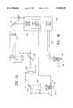
- FIG. 1is a front plane view of the preferred embodiment of the present invention.
- FIG. 2is an illustration of one embodiment of the optical train through the articulated arm of the present invention.
- FIG. 2ais an illustration of an embodiment of the optical train through the articulated arm of the present invention.
- FIG. 2bis an illustration of an embodiment of the present invention in which fiber optic guides the surgical laser beam to the surgical tip.
- FIG. 3is a cross-sectional side view of the surgical tip of the present invention in contact with an applanator plate in accordance with the present invention.
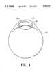
- FIG. 4is a cross-sectional side view of a resulting incision made by the present invention after removing the applanator plate from the corneal epithelium.
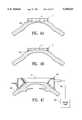
- FIG. 4Ais a cross-sectional side view of a convex applanator plate applied to an eye.
- FIG. 4Bis a cross-sectional side view of a concave applanator plate applied to an eye.
- FIG. 4Cis a cross-sectional side view of the use of a retention ring in accordance with the present invention.
- FIG. 5is a cross-sectional side view of a cornea showing some of the resulting incisions which can be formed in a stroma by the present invention.
- FIG. 6is a top view of a cornea, showing the use of the present invention to make radial incisions on the cornea.
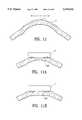
- FIG. 7Ais a cross-sectional side view of the use of a partially curved applanator plate used to create an incision of varying depth within a stroma in contact with a cornea.
- FIG. 7Bis a cross-sectional side view of the cornea of FIG. 7A after the applanator plate has been removed, showing a shallower cut depth near the central region of the cornea and a deeper cut depth near the outer edge of the cornea.
- FIG. 8is a top view of a cornea, showing the use of the present invention to make transverse-cut incisions on the cornea.
- FIG. 9is a cross-sectional side view of a cornea, showing the use of the present invention to remove tissue to a desired depth d over a predetermined area on the cornea, and showing an alternative method for performing a cornea transplant.
- FIG. 10is a cross-sectional side view of a cornea, showing the use of the present invention to correct myopia.
- FIG. 10Ais a cross-sectional side view of a cornea, showing the present invention in contact with the eye to produce the excision shown in FIG. 10.
- FIG. 10Bis a cross-sectional side view of a cornea, showing an alternative embodiment of the present invention in contact with the eye to produce the excision shown in FIG. 10.
- FIG. 10Cis a cross-sectional side view of a cornea, showing an excision used to correct moypia.
- FIG. 10Dis a cross-sectional side view of a cornea, showing a portion of the cornea of FIG. 10C removed, and the exposed cornea bed.
- FIG. 10Eis a cross-sectional side view of a cornea, showing the portion of the cornea of FIG. 10D replaced in the cornea bed.
- FIG. 11is a cross-sectional side view of a cornea, showing the use of the present invention to correct hyperopia.
- FIG. 11Ais a cross-sectional side view of a cornea, showing an applanator plate of the present invention in contact with the eye to produce the excision shown in FIG. 11.
- FIG. 11Bis a cross-sectional side view of a cornea, showing the applanator plate of the present invention in contact with the eye to produce an excision as shown in FIG. 11.
- FIG. 11Cis a cross-sectional side view of a cornea, showing an excision used to correct hyperopia.
- FIG. 11Dis a cross-sectional side view of a cornea, showing a portion of the cornea of FIG. 11C removed, and the exposed cornea bed.
- FIG. 11Eis a cross-sectional side view of a cornea, showing the surface of the cornea of FIG. 11C replaced in the cornea bed.
- FIG. 1is an illustration of the preferred embodiment of the present invention.
- the preferred embodiment of the present inventioncomprises a surgical laser source 100 including a laser system (not shown), such as the system disclosed in a co-pending application for U.S. patent filed by the present inventor, entitled “Method of, and Apparatus for, Surgery of the Cornea” (U.S. application Ser. No. 07/788,424), having a Ti-doped Al 2 O 3 laser emitting pulses at about 100 to about 50,000 laser pulses per second.
- the laser beamis directed to an intended interaction point to be ablated by a laser beam control means, such as the type described in co-pending applications for U.S.
- An articulated arm 103 having flexible joints 107guides the laser beam from the surgical laser source to a surgical tip 109 along a path determined by the disposition of each flexible joint 107.
- the distal end 115 of the surgical tip 109is placed in contact with an applanator plate 111.
- the optical train through the articulated arm 103is shown in detail in FIG. 2.
- four lensesare used to control the beam diameter, within the cross-sectional area of the articulated arm 103 required to direct the surgical beam to each point of interest within the eye.
- the surgical beamis emitted by the surgical laser source 100 and is directed to strike a series of reflective surfaces, such as a polished mirror 310 located at the flexible joint 107, which redirect the beam to follow the path of the articulated arm 103.
- each flexible jointis capable of rotating about one axis of rotation.
- the beamis reflected off the first mirror 310 and passes through the first lens 312.
- the first lens 312has a focal length of f1 and is positioned a distance of f1 from the laser source. Passing the beam through the first lens 312 prevents further divergence of the beam from the local longitudinal axis of the articulated arm 103.
- the beamAfter passing through the first lens 312, the beam propagates a distance f1 and strikes a second mirror 314 located at a second of the flexible joints 107 of the articulated arm 103.
- the second mirror 314redirects the beam once again.
- the beamcontinues propagating through the path of the articulated arm 103 a distance f2 to a second lens 316, having a focal length of f2.
- the beamUpon passing through the second lens 316, the beam begins to converge toward the focal point of that lens a distance f2 ahead.
- the beamstrikes a third mirror 318 located at a third flexible joint 107. The surface of the third mirror 318 is coincident with the focal point of the second lens 316.
- the third mirror 318redirects the beam to continue down the path through the articulated arm 103.
- the beamdiverges from the local longitudinal axis of the articulated arm 103 as it leaves the surface of the third mirror 318.
- a third lens 320 having a focal length of f3is located at a distance f3 from the third mirror 318. The third lens 320 stops the beam from diverging further from the longitudinal axis of the articulated arm 103.
- a fourth mirror 322is located at a fourth flexible joint 107 a distance f3 from the lens 320.
- the beamreflects off the fourth mirror 322 and continues down the path of the articulated arm 103.
- a fourth lens 324 having a focal length f4is located a distance f4 from the mirror 322.
- the fourth lens 324causes the beam to converge toward the focal point located a distance f4 from the lens 324.
- the beamenters the surgical tip 109 at a distance which is less than the distance f4. Once the beam enters the surgical tip 109, the beam is finely focussed to a spot beam at the interaction point 307.
- the combination of lenses and mirrors of the articulated arm 103provide a means by which points on a frame of reference fixed with respect to the laser source 100 can be mapped into a second frame of reference fixed with respect to the surgical tip 109 at the end of the relatively long and narrow articulated arm 103.
- the particular configuration of mirrors and lenses described hereinis merely meant to be illustrative of the means by which the beam is directed to the surgical tip 109.
- Alternative embodiments in which the mirrors have curved surfaces and the number of optical elements vary from that illustratedare possible and remain within the scope of the present invention.
- FIG. 3is an illustration of the surgical tip 109 of the present invention which is in contact with an applanator plate 111 made and used in accordance with the present invention.
- the applanator plate 111is in contact with the corneal epithelium 113 of a patient's eye 105.
- a wetting solutionsuch as a saline solution
- Optical focusing elements 301are used to focus the interaction point of the surgical beam in known fashion.
- the applanator plate 111is preferably constructed of a transparent light weight plastic, such as acrylic, having an index of refraction that closely matches that of a cornea (i.e., approximately 1.38).
- the applanator plate 111has at least two planar surfaces, a tip surface 302 in contact with the surgical tip 109 and a corneal surface 303 in contact with epithelium 113.
- the applanator plate 111is placed in contact with the corneal epithelium 113 and deforms the cornea to conform to the shape of the corneal surface 303.
- the corneal surface 303 of the applanator plate 111may be shaped to conform the cornea to any contour that would be helpful in performing a particular surgical procedure.
- the corneal surface 303 of the applanator plate 111may be planar, convex or concave with a spheric or aspheric curvature, or may conform to any irregular shape that would be advantageous for the surgical procedure to be performed.
- the applanator plate 111may have a convex corneal surface 303 which deforms the cornea such that incisions may be made which are close to the epithelium at the center of the cornea, but which are further away from the epithelium toward the edges of the cornea.
- FIG. 4Bshows an applanator plate 111 having a concave corneal surface 303 having a curvature that matches the curvature of the eye has the advantage of creating no beam distortion, and little or no corneal deformation. Furthermore in an alternative embodiment of the present invention, the corneal surface 303 may have a rough texture.
- the area of contact between the applanator plate 111 and the corneais preferably about 0.5 mm to 20 mm in diameter, as selected by a surgeon.
- the applanator plate 111creates a prepared area on an eye for conducting a surgical procedure with a laser beam.
- a non-linear incisionmay be made by moving the beam linearly.
- Control of the surgical beam in a two-dimensional (X, Y) plane perpendicular to the longitudinal axis of the surgical tip 109results in a three-dimensional incision.
- the approximately lineal incision 305 shown in FIG. 3was created by moving the surgical beam along a single axis.
- FIG. 4illustrates the resulting incision 305 after removing the applanator plate 111 from the corneal epithelium 113. It can be seen from FIG. 4 that the resulting incision 305 follows the curvature of the surface of the epithelium 113. This greatly simplifies the control of the laser beam. In particular, the use of a plano-plano applanator plate 111 makes it possible to follow the contour of the surface of the epithelium 113 without complex apparatus to determine the contour thereof, or the need to control the beam in more than two dimensions.
- Control of the interaction point of the laser beam in the Z-axisis accomplished by moving one or more lenses in the optical train (see FIG. 2) from the laser source to the last lens in the surgical tip 109. Such movement may be done manually or under automated control (for example, by a computer-controlled actuator such as a galvanometer drive).
- the tip surface 302 of the applanator plate 111is planar. This reduces the distortion that would otherwise occur as the laser beam crosses the boundary from the air above the applanator plate 111 into the applanator plate 111 due to the difference in the index of refraction between the air and the applanator plate 111.
- the applanator plate 111preferably has an index of refraction close to that of the stroma of an eye, the curved boundary between the corneal surface 303 of the applanator plate 111 and the epithelium does not distort the surgical laser beam.
- the contour of the tip surface 302 of the applanator plate 111may be other than planar.
- the surfacemay be either convex or concave, with a spheric or aspheric curvature, or may conform to any irregular shape that would be advantageous for the surgical procedure to be performed.
- a convex tip surface 302can be used as a focusing element for the laser beam, allowing a small f number optics, and consequently a more tightly focused interaction point.
- the applanator plate 111provides a rigid reference point for the surgical tip 109 with respect to the eye 105. Therefore, very accurate work can be done with the laser beam without risk that the beam will accidentally contact the endothelium 401. This is critical, since any contact between the interaction point 307 of the laser beam and the endothelium 401 may cause permanent damage to the eye 105, as the endothelium 401 is vital for bringing nutrients to the eye 105 and does not regenerate in humans. (See FIG. 4).
- the entire eye 105cannot move with respect to the reference used to guide the positioning of the interaction point 307.
- a simple ultrasonic distance measuring apparatussuch as a pachymeter, can be used to determine the relative location of each of the relevant regions within the cornea, such as the endothelium, and Bowman's layer. This information permits a surgeon to focus the surgical beam with the optical focusing elements 301 to locate the interaction point 301 at a desired depth within the eye 105.
- the applanator plate 111may be secured to the eye by a retention ring attached to the scleral-corneal region of the eye.
- the retention ringmay be held in place by partial vacuum pressure generated by a vacuum pump coupled to the retention ring.
- FIG. 4Cillustrates the use of a retention ring 501 in accordance with the present invention. Vacuum line 503 creates a vacuum pressure against the sclera 505, thereby preventing the applanator plate 111 from moving with respect to the eye 105.
- a major advantage of the present inventionis the ease and accuracy with which interior portions of the stroma can be liquified, vaporized, or welded (i.e., heat melted). It is well known that incisions made within the stroma and which preserve the Bowman's layer and the epithelium have the advantages of (1) reduced pain, (2) faster healing, and (3) no post-operative haze.
- FIG. 5illustrates some of the resulting incisions which can be formed in a stroma 601. The incisions shown in FIG.
- the incisions illustrated in FIG. 5include a straight channel 603, a curved channel 605, a point 607, a line 609, an interrupted line 611, a curve of varying depth 613, a circular area 615, a square or parallelepiped area 617, or a spiral 619.
- the inventionencompasses any combination of such incisions.
- the lasermay be either a continuous wave (CW) or pulsed (shuttered) laser.
- the applanator plate 111may be marked to aid in guiding the laser beam during the surgical procedure.
- the laser surgical system of the present inventioncan perform numerous types of surgical procedures on Bowman's layer, the stroma, anterior capsule, lens, posterior capsule, iris, vitreoretinal membranes, and the retina.
- two types of laser tissue interactionare particularly suited for the inventive system:
- the inventive systemcan easily create straight line and curved-line excisions, of any predetermined length and depth, at a very precise location determined by a surgeon.
- multiple radial cuts 902equal or partially equal in incision length and with an angular separation between cuts, can be made on the cornea with the present surgical system.
- An incisioncan be made by directing the surgical laser beam to a predetermined location at the cornea, and removing the desired amount of tissue by controlling the laser beam energy dosage.
- the incisionmay be made with either a wide incision width by using a larger beam spot size on the cornea surface, or a fine incision width by using a more focussed beam spot.
- the depth of each cutcan be very accurately varied over the length of the cut, either by directly controlling the location and volume of the interaction point, or by varying the contour of the surface of the applanator plate 111a which is in contact with the epithelium 113, as shown in FIG. 7A.
- FIG. 7Aillustrates an incision having a shallow portion 904 and a deep portion 905. Such an incision may be made entirely within the stroma without disruption of the epithelium, endothelium, or Bowman's layer.
- a side view of a cross-section of the cornea after the applanator plate 111a has been removedshows a shallower cut depth 904 near the central region of the cornea and a deeper cut depth 905 near the outer edge of the cornea.
- the inventioncan also easily generate transverse cuts ("T-cuts"), as shown in FIG. 8.
- T-cutstransverse cuts
- the surgical laser beamBy directing the surgical laser beam to make a pair of opposing transverse excisions 906 along an axis 908 relative to the center of the eye, the refractive power of the eye is decreased along the axis.
- the exact length d and the location of the incisioncan vary according to the amount of desired correction, in known fashion.
- the inventive systemcan also be used for procedures in cornea transplants.
- a circumcision of the cornea in any predetermined shapee.g., circular, elliptical, hexagonal, etc.
- a computer control unitas described in the co-pending application for U.S. patent entitled “Method of, and Apparatus for, Surgery of the Cornea” (U.S. patent application Ser. No. 07/788,424), calculates the beam location based on the location of the applanator plate 111 relative to the location of the desired incision, the particular shape incision, and the amount of laser energy needed to cut through the cornea.
- excisions in the corneacan be made at effective locations for performing radial keratotomies or making T-cuts, to correct myopia, hyperopia, or astigmatism (regular or irregular).
- the second important type of laser-tissue interaction provided by the inventive systemis area ablation, which permits direct sculpting of the corneal surface.
- a local scar or infected tissuecan be removed with the present invention.
- the defective tissueis removed to a desired depth d over a predetermined area on the cornea.
- a donor cornea capcan be cut and ablated ("sculpted") to the desired dimension, curvature, and thickness using the invention described in co-pending U.S. patent application Ser. No. 07/788,424.
- the cap pieceis then transferred to the bared stroma bed and attached by suture, glue, or other appropriate means, in known fashion.
- Such a capcan be used to change the refractive power of the eye to correct myopia, hyperopia, or astigmatism (regular or irregular).
- FIG. 9an alternative method is shown for performing a cornea transplant.
- the inventioncan be used to ablate the cornea most of the way or all of the way through, from the epithelium to the endothelium of the cornea. Then a donor cornea 1001 is cut to matching dimensions, and attached to the open ablated area by sutures or other known methods.
- the curvature of the corneacan be reduced by selectively ablating the cornea in such a way that more tissue is removed at the center portion C of the cornea, with a decreasing amount of tissue being removed towards the periphery P of the cornea.
- the inventive systemcan also be applied to ablate the corneal tissue near the surface of cornea.
- the new desired profile of the eyemay include Bowman's membrane and part of the stromal layer, depending on the amount of refractive correction required.
- the computer control unit 114provides for the sequence, location, and intensity of laser pulses to be deposited.
- the deposition patternis preferably in accordance with the patterns discussed in the section "Method of Depositing Laser Pulses" within the pending application.
- the applanator plate 111may have a concave corneal surface 303 as shown in FIG. 10A, or may have a planar corneal surface 303 as shown in FIG. 10B.
- the interaction point of the surgical laser beamchanges position in only the X-axis and Y-axis.
- the applanator plate 111has a planar corneal surface 303, the position of the interaction point of the surgical laser beam is changed in the Z-axis, as well as in the X-axis and Y-axis.
- FIG. 10Cillustrates an ablated area 2000 within the stroma 2001 of an eye 2003 without disrupting the surface 2005 of the cornea.
- An applanator plate 111 having a planar corneal surface 303is placed in contact with the cornea.
- the surgical laser beamis directed to ablate a first area of the interior of the stroma at a first fixed distance from the surface of the cornea.
- the surgical laser beamis directed to a second area of the interior of the stroma adjacent to the first area, and at a second fixed distance from the surface of the cornea.
- the second distanceis less than the first distance, and the second area is smaller than the first area. This procedure is repeated to ablate a predetermined volume defining a cavity.
- the cavityhas a convex-convex shape, more tissue being removed near center of the convex-convex cavity.
- the depth of the cavitydiminishes towards the end of the cavity.
- the tissue in the ablated volume 2000is either liquified or vaporized.
- the liquid or vaporis absorbed by the surrounding unablated tissue. Therefore, the surface of the cornea above the ablated volume 2000 settles down such that the overall curvature of the cornea is reduced.
- the present inventionhas the advantage of maintaining a fixed reference with respect to the surface of the cornea, even as corneal tissue is removed by vaporization. Thus, precise ablation of the interior of the stroma is possible.
- a portion 2007 of the corneais removed after the procedure illustrated in FIG. 10C has been performed. Once the portion 2007 of the cornea has been removed, the portion 2007 is replaced such that that portion 2007 relaxes to conform to the cavity bed resulting in a reduction in the curvature. Such precision is difficult to achieve using an eye-tracking device.
- FIG. 11Aillustrates the use of an applanator plate having a convex corneal surface 303 used to create the excision shown in FIG. 11.
- FIG. 11Billustrates the use of an applanator plate having a planar corneal surface 303.
- the inventionis particularly useful for the correction of asymmetric refractive errors. Irregular distortions may result from poor matching of a cornea from a transplant, uneven suturing, or from imperfect refractive surgical procedures such as lameliar keratomileusis or epikeratophakia.
- the inventive systemcan direct the surgical laser beam to any desired location to sculpt the cornea according to a predetermined shape. The surgical laser beam thus can be applied to smooth out an irregular corneal profile.
- FIG. 11Cillustrates an ablated volume 2010 within the stroma 2011 of an eye 2013 without disrupting the surface 2015 of the cornea.
- An applanator plate 111 having a planar corneal surface 303is placed in contact with the cornea.
- the surgical laser beamis directed to ablate a first area of the interior of the stroma at a first fixed distance from the surface of the cornea.
- the surgical laser beamis directed to a second area of the interior of the stroma adjacent to the first area, and at a second fixed distance from the surface of the cornea.
- the second distanceis donut shaped, with the outside radius of the second area being smaller than the outside radius of the first area. This procedure is repeated to ablate a volume 2010 having a donut shaped cavity.
- the tissue in the ablated volume 2010is either liquified or vaporized.
- the liquid or vaporis absorbed by the surrounding unablated tissue. Therefore, the surface of the cornea above the ablated volume 2010 settles down such that the overall curvature of the cornea is increased.
- the surfacemay be removed as described in the discussion of FIGS. 10D and 10E.
- FIG. 11Dillustrates an eye in which the portion 2017 of the cornea is removed after the procedure illustrated in FIG. 11C has been performed.
- the portion 2017is replaced such that that portion 2017 relaxes to conform to the cavity bed resulting in an increase in the curvature.
- the surface section 2017 which was removedconforms to the bottom of the cavity formed when the area 2010 of the stroma was ablated. This results in a smooth corneal surface 2015 with an improved radius of curvature.
- the above described methodmay be used to correct regular or irregular astigmatism, or complex refractive errors.
- the amount and distribution of tissue to be removed from various locations within the stromais determined by the amount of correction required.
- Another use of the inventionis to produce standard or custom sculpted cornea caps in advance of need.
- the inventioncan be used on a donor cornea or a synthetic cornea substitute to ablate a desired profile to correct for myopia, hyperopia, or astigmatism. Such sculpted caps can then be attached to a properly prepared cornea, in known fashion.
- the present inventionis also very useful for performing surgical procedures to correct glaucoma by creating a one or more openings through an iris to release fluids from the posterior chamber which create undesirable pressure behind the cornea.
- one or more excisionsmay be created in the posterior or anterior capsule to permit removal of material from the capsule and to implant an interocular lens (IOL) or any other material or structure.
- IOLinterocular lens
- portions of the retinal membrane which create tension on the retinamay be cut to relieve such tension.
- portions of the retinamay be operated upon to remove harmful tissue.
- the inventionprecisely controls and determines the location of the interaction point of a surgical laser beam, and controls the shape of the cornea during ophthalmic surgery.
- An articulated arm having flexible jointsfollows any motion of the eye.
- the applanator platealso provides a means to control the contour of the index of refraction boundary between the corneal epithelium of the eye and the air.
- the surgical laser beammay be delivered to the surgical tip in any manner that permits an exact mapping of the position of the surgical laser beam into a frame of reference fixed to the applanator plate.
- a system having a fiber optic path from the surgical laser source to a beam control unit, fixed to the applanator plate, which receives commands from the beam control system within the surgical laser source and accordingly directs the beam through the applanator platewould fall within the scope of the present invention.
- any appropriate laser mediummay be used in generating the surgical laser beam.
- any appropriate beam control meansmay be used.
Landscapes
- Health & Medical Sciences (AREA)
- Ophthalmology & Optometry (AREA)
- Optics & Photonics (AREA)
- Physics & Mathematics (AREA)
- Heart & Thoracic Surgery (AREA)
- Surgery (AREA)
- Engineering & Computer Science (AREA)
- Biomedical Technology (AREA)
- Nuclear Medicine, Radiotherapy & Molecular Imaging (AREA)
- Vascular Medicine (AREA)
- Life Sciences & Earth Sciences (AREA)
- Animal Behavior & Ethology (AREA)
- General Health & Medical Sciences (AREA)
- Public Health (AREA)
- Veterinary Medicine (AREA)
- Laser Surgery Devices (AREA)
Abstract
Description
Claims (61)
Priority Applications (1)
| Application Number | Priority Date | Filing Date | Title |
|---|---|---|---|
| US07/967,253US5549632A (en) | 1992-10-26 | 1992-10-26 | Method and apparatus for ophthalmic surgery |
Applications Claiming Priority (1)
| Application Number | Priority Date | Filing Date | Title |
|---|---|---|---|
| US07/967,253US5549632A (en) | 1992-10-26 | 1992-10-26 | Method and apparatus for ophthalmic surgery |
Publications (1)
| Publication Number | Publication Date |
|---|---|
| US5549632Atrue US5549632A (en) | 1996-08-27 |
Family
ID=25512521
Family Applications (1)
| Application Number | Title | Priority Date | Filing Date |
|---|---|---|---|
| US07/967,253Expired - LifetimeUS5549632A (en) | 1992-10-26 | 1992-10-26 | Method and apparatus for ophthalmic surgery |
Country Status (1)
| Country | Link |
|---|---|
| US (1) | US5549632A (en) |
Cited By (217)
| Publication number | Priority date | Publication date | Assignee | Title |
|---|---|---|---|---|
| US5957915A (en)* | 1995-01-23 | 1999-09-28 | Coherent, Inc. | Hand-held laser scanner |
| US6036683A (en)* | 1997-01-02 | 2000-03-14 | G. Rodenstock Instruments Gmbh | Process and apparatus for changing the curvature of the cornea |
| EP0993814A1 (en)* | 1998-10-15 | 2000-04-19 | Intralase Corporation | Corneal aplanation device |
| EP1034755A1 (en)* | 1999-03-11 | 2000-09-13 | Intralase Corporation | Ophthalmic laser system including disposable contact lens |
| US6146405A (en)* | 1999-02-11 | 2000-11-14 | Johnston; Robert M. | Ophthalmic applanator |
| EP1034757A3 (en)* | 1999-03-11 | 2001-09-05 | Intralase Corporation | Device for removing gas and tissue debris |
| US20020103481A1 (en)* | 2001-01-29 | 2002-08-01 | Webb R. Kyle | Ocular fixation and stabilization device for ophthalmic surgical applications |
| USD462442S1 (en) | 2001-04-11 | 2002-09-03 | Intralase Corporation | Suction ring for ophthalmic laser surgery |
| USD462443S1 (en) | 2001-04-11 | 2002-09-03 | Intralase Corporation | Applanation lens cone for ophthalmic laser surgery |
| WO2002083018A1 (en)* | 2001-04-13 | 2002-10-24 | Intralase Corp. | Device and method for reducing corneal induced aberrations during ophthalmic laser surgery |
| DE19943723C2 (en)* | 1999-09-03 | 2002-11-07 | Zeiss Carl Jena Gmbh | Device for irradiating the eye |
| US6478792B1 (en) | 1999-09-03 | 2002-11-12 | Carl Zeiss Jena Gmbh | Method and apparatus for illumination of the eye |
| WO2003002008A1 (en)* | 2001-06-29 | 2003-01-09 | Intralase Corp. | Improved applanation lens and method for ophthalmic surgical applications |
| US20030018347A1 (en)* | 2001-07-23 | 2003-01-23 | Ioannis Pallikaris | Device for separating the epithelium layer from the surface of the cornea of an eye |
| US20030053219A1 (en)* | 2001-07-30 | 2003-03-20 | Manzi David J. | Lens system and method |
| US6551306B1 (en)* | 1999-04-13 | 2003-04-22 | Cesar C. Carriazo | Refractive laser ablation through topography |
| US20030212387A1 (en)* | 2002-03-23 | 2003-11-13 | Intralase Corp. | System and method for improved material processing using a laser beam |
| US20040215065A1 (en)* | 2001-05-23 | 2004-10-28 | Setten Gysbert Van | Materials and methods for visualizing and illuminating the lens and anterior lens capsule of the eye |
| US6818004B2 (en) | 2001-10-24 | 2004-11-16 | Cesar C. Carriazo | Aspherical positioning ring |
| EP1486185A1 (en) | 2003-06-10 | 2004-12-15 | SIE AG, Surgical Instrument Engineering | Opthalmological device for ablation of eye tissue |
| US20050043722A1 (en)* | 2003-08-22 | 2005-02-24 | Lin J. T. | Methods and apparatus for treatment of eye disorders using articulated-arm-coupled ultraviolet lasers |
| US20050096639A1 (en)* | 2000-05-08 | 2005-05-05 | Michael Slatkine | Non-penetrating filtration surgery |
| WO2005039462A1 (en) | 2003-10-23 | 2005-05-06 | Carl Zeiss Meditec Ag | Laser machining |
| US20050113813A1 (en)* | 2003-11-20 | 2005-05-26 | Josef Bille | Eye position control monitor for laser vision correction |
| WO2005048896A1 (en) | 2003-11-14 | 2005-06-02 | Carl Zeiss Meditec Ag | Adapter for coupling a laser processing device to an object |
| US20050143718A1 (en)* | 2004-12-02 | 2005-06-30 | Sie Ag Surgical Instrument Engineering | Method for surgical treatment of a patient's eye by means of a laser |
| WO2005079717A1 (en)* | 2004-02-25 | 2005-09-01 | Carl Zeiss Meditec Ag | Contact element for laser machining |
| US20050192562A1 (en)* | 2004-03-01 | 2005-09-01 | Frieder Loesel | System and method for positioning a patient for laser surgery |
| US20060000812A1 (en)* | 2004-07-02 | 2006-01-05 | Jan Weber | Method and apparatus for controlling and adjusting the intensity profile of a laser beam employed in a laser welder for welding polymeric and metallic components |
| US20060044510A1 (en)* | 1996-12-23 | 2006-03-02 | University Of Rochester | Method and apparatus for improving vision and the resolution of retinal images |
| US20060095023A1 (en)* | 2004-11-01 | 2006-05-04 | Frieder Loesel | Time-resolved scanning patterns for intrastromal surgery |
| US20060106372A1 (en)* | 2004-11-12 | 2006-05-18 | Tobias Kuhn | Systems and methods for intrastromal scanning patterns |
| US20060111697A1 (en)* | 2003-07-11 | 2006-05-25 | Medizinisches Laserzentrum Luebeck Gmbh | Method for operation of laser |
| US20060155264A1 (en)* | 2004-09-20 | 2006-07-13 | Hovanesian John A | Methods and apparatus for vision correction |
| US20060155265A1 (en)* | 1995-03-20 | 2006-07-13 | Intralase Corp. | Method of corneal surgery by laser incising a contoured corneal flap |
| US20060195075A1 (en)* | 2003-07-18 | 2006-08-31 | Dirk Muhlhoff | Method and device for forming curved sections in a transparent material |
| US20060192921A1 (en)* | 2005-02-25 | 2006-08-31 | Frieder Loesel | Device and method for aligning an eye with a surgical laser |
| US20060217688A1 (en)* | 1991-11-06 | 2006-09-28 | Lai Shui T | Method and Apparatus for Laser Surgery of the Cornea |
| US20060253110A1 (en)* | 2005-05-09 | 2006-11-09 | Rosen Robert S | Device for conjunctival/scleral compression to constrict superficial blood flow and method of use |
| EP1731120A1 (en) | 2005-06-09 | 2006-12-13 | SIE AG, Surgical Instrument Engineering | Ophthalmological device for ablation of eye tissue. |
| US20060287662A1 (en)* | 2005-05-26 | 2006-12-21 | Ntk Enterprises, Inc. | Device, system, and method for epithelium protection during cornea reshaping |
| US20070016234A1 (en)* | 2003-05-02 | 2007-01-18 | Albert Daxer | Device for cutting the cornea of an eye |
| US20070027438A1 (en)* | 2005-07-26 | 2007-02-01 | Frieder Loesel | System and method for compensating a corneal dissection |
| DE19943735B4 (en)* | 1999-09-03 | 2007-04-26 | Carl Zeiss Meditec Ag | Device for irradiating the eye |
| US20070093795A1 (en)* | 2005-10-21 | 2007-04-26 | Markus Melcher | Cornea contact system |
| US20070093796A1 (en)* | 2005-10-24 | 2007-04-26 | Intralase Corp. | Disposable patient interface |
| US7220256B2 (en) | 2001-03-13 | 2007-05-22 | Hobart James L | Laser system and method for treatment of biological tissues |
| US20070151963A1 (en)* | 2005-12-20 | 2007-07-05 | Koichiro Tanaka | Laser irradiation apparatus, laser irradiation method, and method for manufacturing semiconductor device |
| US20070173791A1 (en)* | 2006-01-20 | 2007-07-26 | Intralase Corp. | System for ophthalmic laser surgery |
| US20070208325A1 (en)* | 2006-03-06 | 2007-09-06 | Intralase Corp. | Method of transplanting a cornea |
| US20070219541A1 (en)* | 2006-03-14 | 2007-09-20 | Intralase Corp. | System and method for ophthalmic laser surgery on a cornea |
| US20070219543A1 (en)* | 2006-03-17 | 2007-09-20 | Visx, Incorporated | Intrastromal Refractive Correction Systems and Methods |
| US20070237620A1 (en)* | 2003-11-19 | 2007-10-11 | Muehlhoff Dirk | Adapter for Mechanically Coupling a Laser Processing Device to an Object |
| US20070258046A1 (en)* | 2006-02-14 | 2007-11-08 | Lai Shui T | Subjective Wavefront Refraction Using Continuously Adjustable Wave Plates of Zernike Function |
| WO2007130221A2 (en) | 2006-04-07 | 2007-11-15 | Amo Development, Llc | Adaptive pattern correction for laser scanners |
| US20070293851A1 (en)* | 2003-07-25 | 2007-12-20 | Carl Zeiss Meditec Ag | Method and Device for Producing Curved Cuts in a Transparent Material |
| US20070291224A1 (en)* | 2006-06-15 | 2007-12-20 | Lai Shui T | High Visual Acuity Contact Lenses |
| US20080039825A1 (en)* | 2006-07-26 | 2008-02-14 | Lai Shui T | Intrastromal Surgery Correcting Low Order and High Order Aberrations of the Eye |
| US20080037135A1 (en)* | 2006-07-25 | 2008-02-14 | Lai Shui T | Method of Making High Precision Optics Having a Wavefront Profile |
| EP1889588A1 (en) | 2006-07-04 | 2008-02-20 | WaveLight AG | Improved contact lens |
| US20080058777A1 (en)* | 2006-09-05 | 2008-03-06 | Intralase Corp. | System and method for resecting corneal tissue using non-continuous initial incisions |
| US20080058841A1 (en)* | 2006-09-05 | 2008-03-06 | Kurtz Ronald M | System and method for marking corneal tissue in a transplant procedure |
| WO2008030698A2 (en) | 2006-09-05 | 2008-03-13 | Amo Development, Llc | System and method for resecting corneal tissue |
| US20080078752A1 (en)* | 2006-09-29 | 2008-04-03 | Carl Zeiss Meditec Ag | Apparatus and method for material processing using a transparent contact element |
| US20080082086A1 (en)* | 2006-09-05 | 2008-04-03 | Kurtz Ronald M | System and method for resecting corneal tissue |
| US20080183159A1 (en)* | 2005-08-25 | 2008-07-31 | Dirk Preuss | Contact glass for ophtalmologic surgery |
| US20080186551A1 (en)* | 2005-03-26 | 2008-08-07 | Carl Zeiss Meditec Ag | Scanning Device |
| US20080212024A1 (en)* | 2006-09-18 | 2008-09-04 | Lai Shui T | Customized contact lenses for reducing aberrations of the eye |
| US20080234667A1 (en)* | 2005-09-27 | 2008-09-25 | Stefan Lang | System and Method for the Treatment of a Patients Eye Working at High Speed |
| DE102007020565A1 (en) | 2007-04-26 | 2008-10-30 | Carl Zeiss Meditec Ag | Contact glass with mark |
| US20080287927A1 (en)* | 2004-12-02 | 2008-11-20 | Sie Ag Surgical Instrument Engineering | Protective device for ophthalmic laser treatment |
| US20080319428A1 (en)* | 2006-11-10 | 2008-12-25 | Carl Zeiss Meditec Ag | Treatment apparatus for surgical correction of defective eyesight, method of generating control data therefore, and method for surgical correction of defective eyesight |
| US20090054879A1 (en)* | 2007-08-23 | 2009-02-26 | Ntk Enterprises, Inc. | System and method for defining and controlling ltk and other surgical eye procedures to produce little or no stromal collagen shrinkage |
| US20090069794A1 (en)* | 2007-09-10 | 2009-03-12 | Kurtz Ronald M | Apparatus, Systems And Techniques For Interfacing With An Eye In Laser Surgery |
| US20090076601A1 (en)* | 2006-03-16 | 2009-03-19 | Albert Daxer | Cornea Implant |
| WO2009033111A3 (en)* | 2007-09-06 | 2009-04-30 | Lensx Lasers Inc | Precise targeting of surgical photodisruption |
| US20090118716A1 (en)* | 2007-11-07 | 2009-05-07 | Intralase, Inc. | System and method for scanning a pulsed laser beam |
| DE102007053281A1 (en) | 2007-11-08 | 2009-05-14 | Carl Zeiss Meditec Ag | A treatment device for operative vision correction of an eye, a method for generating control data therefor and methods for surgical correction of defective vision of an eye |
| DE102007053283A1 (en) | 2007-11-08 | 2009-05-14 | Carl Zeiss Meditec Ag | A treatment device for operative vision correction of an eye, a method for generating control data therefor and methods for surgical correction of defective vision of an eye |
| US20090137993A1 (en)* | 2007-09-18 | 2009-05-28 | Kurtz Ronald M | Methods and Apparatus for Integrated Cataract Surgery |
| US20090137991A1 (en)* | 2007-09-18 | 2009-05-28 | Kurtz Ronald M | Methods and Apparatus for Laser Treatment of the Crystalline Lens |
| US20090137988A1 (en)* | 2007-11-02 | 2009-05-28 | Lensx Lasers, Inc | Methods And Apparatus For Improved Post-Operative Ocular Optical Performance |
| US20090143772A1 (en)* | 2007-09-05 | 2009-06-04 | Kurtz Ronald M | Laser-Induced Protection Shield in Laser Surgery |
| US20090149840A1 (en)* | 2007-09-06 | 2009-06-11 | Kurtz Ronald M | Photodisruptive Treatment of Crystalline Lens |
| US20090149841A1 (en)* | 2007-09-10 | 2009-06-11 | Kurtz Ronald M | Effective Laser Photodisruptive Surgery in a Gravity Field |
| US20090157063A1 (en)* | 2007-12-17 | 2009-06-18 | Luis Antonio Ruiz | Method patterns for intrastromal refractive surgery |
| US20090157061A1 (en)* | 2007-12-17 | 2009-06-18 | Luis Antonio Ruiz | Method for intrastromal refractive surgery |
| US20090177497A1 (en)* | 2008-01-09 | 2009-07-09 | Ferenc Raksi | Ophthalmic Surgical Systems with Automated Billing Mechanism |
| US20090177189A1 (en)* | 2008-01-09 | 2009-07-09 | Ferenc Raksi | Photodisruptive laser fragmentation of tissue |
| US20090240327A1 (en)* | 2006-05-23 | 2009-09-24 | Albert Daxer | Corneal Implant and Method for Correction of Impaired Vision in the Human Eye |
| US20090247997A1 (en)* | 2008-04-01 | 2009-10-01 | Amo Development, Llc | Ophthalmic laser apparatus, system, and method with high resolution imaging |
| US20090247999A1 (en)* | 2008-04-01 | 2009-10-01 | Amo Development, Llc | Corneal implant system, interface, and method |
| DE102008017293A1 (en) | 2008-04-04 | 2009-10-08 | Carl Zeiss Meditec Ag | A method of generating control data for ophthalmic surgery and ophthalmic surgical apparatus and methods |
| EP2133048A1 (en) | 2007-03-14 | 2009-12-16 | WaveLight AG | Apparatus for connecting an element to an eye |
| WO2009152838A1 (en)* | 2008-06-20 | 2009-12-23 | Wavelight Ag | Device for cutting a tissue part with focussed laser radiation |
| WO2009158723A2 (en) | 2008-06-27 | 2009-12-30 | Amo Development, Llc. | Intracorneal inlay, system, and method |
| WO2010022745A1 (en) | 2008-08-25 | 2010-03-04 | Wavelight Ag | Coupling of an eye to a laser device |
| WO2010036859A1 (en) | 2008-09-26 | 2010-04-01 | Amo Development Llc | Laser modification of intraocular lens |
| US20100130966A1 (en)* | 2008-11-21 | 2010-05-27 | Advanced Medical Optics, Inc. | Apparatus, System and Method for Precision Depth Measurement |
| US20100137849A1 (en)* | 2007-04-26 | 2010-06-03 | Carl Zeiss Meditec Ag | Multiple-spot laser refractive ophthalmic surgery |
| US20100133246A1 (en)* | 2008-12-01 | 2010-06-03 | Amo Development, Llc | System and method for multibeam scanning |
| US20100174274A1 (en)* | 2009-01-06 | 2010-07-08 | Bille Josef F | Minimizing the side-effects of refractive corrections using statistically determined irregularities in intrastromal incisions |
| EP2206478A1 (en)* | 2000-05-08 | 2010-07-14 | I Optima Ltd. | Apparatus for non-penetrating filtration surgery |
| DE102009005482A1 (en) | 2009-01-21 | 2010-07-22 | Carl Zeiss Meditec Ag | Device and method for generating control data for the surgical ametropia correction of an eye |
| US20100191227A1 (en)* | 2009-01-27 | 2010-07-29 | Bille Josef F | System and Method for Correcting Higher Order Aberrations with Changes in Intrastromal Biomechanical Stress Distributions |
| US20100191228A1 (en)* | 2009-01-27 | 2010-07-29 | Luis Antonio Ruiz | System and Method for Refractive Surgery with Augmentation by Intrastromal Corrective Procedures |
| US20100191229A1 (en)* | 2009-01-27 | 2010-07-29 | Bille Josef F | Methods for Employing Intrastromal Corrections in Combination with Surface Refractive Surgery to Correct Myopic/Hyperopic Presbyopia |
| WO2010091419A1 (en) | 2009-02-09 | 2010-08-12 | Amo Development Llc. | System and method for intrastromal refractive correction |
| DE102009009382A1 (en) | 2009-02-18 | 2010-08-19 | Carl Zeiss Meditec Ag | Control data producing device for controlling treatment device for corrective surgery of defective vision of eye of patient, determines control data such that volumes lying at edge of lamella are ablated or removed according to control data |
| US20100217247A1 (en)* | 2009-02-20 | 2010-08-26 | Bille Josef F | System and Methods for Minimizing Higher Order Aberrations Introduced During Refractive Surgery |
| US20100256965A1 (en)* | 2009-04-02 | 2010-10-07 | Christian Rathjen | System for defining cuts in eye tissue |
| EP2277481A2 (en) | 2006-04-11 | 2011-01-26 | WaveLight GmbH | Laser arrangement for ophthalmic surgery |
| US20110022037A1 (en)* | 2009-01-06 | 2011-01-27 | Bille Josef F | System and Method for Minimizing the Side Effects of Refractive Corrections Using Line or Dot Cuts for Incisions |
| US20110028952A1 (en)* | 2009-07-29 | 2011-02-03 | Lensx Lasers, Inc. | Optical System with Multiple Scanners for Ophthalmic Surgical Laser |
| US20110028958A1 (en)* | 2009-07-29 | 2011-02-03 | Lensx Lasers, Inc. | Optical System for Ophthalmic Surgical Laser |
| US20110028953A1 (en)* | 2009-07-29 | 2011-02-03 | Lensx Lasers, Inc. | Optical System for Ophthalmic Surgical Laser |
| EP2298255A1 (en) | 2006-11-10 | 2011-03-23 | Carl Zeiss Meditec AG | Planning device for preparing control data for a treatment device for operatively correcting defective vision, treatment device for operatively correcting defective vision and method for preparing control date therefor |
| WO2011035793A1 (en)* | 2009-09-23 | 2011-03-31 | Wavelight Gmbh | Apparatus for ophthalmological laser surgery |
| WO2011038748A1 (en)* | 2009-09-30 | 2011-04-07 | Wavelight Gmbh | Device for ophthalmological laser surgery |
| WO2011042031A1 (en)* | 2009-10-05 | 2011-04-14 | Wavelight Gmbh | Device for ophthalmological laser surgery |
| US20110098790A1 (en)* | 2009-10-26 | 2011-04-28 | Albert Daxer | Methods for treating corneal disease |
| US20110118713A1 (en)* | 2009-11-16 | 2011-05-19 | Lensx Lasers, Inc. | Variable Stage Optical System For Ophthalmic Surgical Laser |
| US20110137299A1 (en)* | 2009-12-07 | 2011-06-09 | Wavelight Ag | Apparatus for Laser Surgical Ophthalmology |
| US20110184394A1 (en)* | 2010-01-22 | 2011-07-28 | Wavelight Ag | Apparatus for Cutting a Human Cornea |
| US20110190739A1 (en)* | 2010-01-29 | 2011-08-04 | Lensar, Inc. | Servo controlled docking force device for use in ophthalmic applications |
| US20110319873A1 (en)* | 2010-06-25 | 2011-12-29 | Ferenc Raksi | Adaptive Patient Interface |
| DE102010031348A1 (en) | 2010-07-14 | 2012-01-19 | Carl Zeiss Meditec Ag | Control data generation for ophthalmologic defecation treatment |
| CN102625684A (en)* | 2009-07-24 | 2012-08-01 | 能斯雅有限公司 | Laser systems and methods for correction of induced astigmatism and correction of astigmatism associated with cataract treatment |
| US8265364B2 (en) | 2010-02-05 | 2012-09-11 | Alcon Lensx, Inc. | Gradient search integrated with local imaging in laser surgical systems |
| US20120283708A1 (en)* | 2011-05-06 | 2012-11-08 | Ferenc Raksi | Adjusting ophthalmic docking system |
| EP2529712A1 (en) | 2006-11-10 | 2012-12-05 | Carl Zeiss Meditec AG | Device for the corrective surgery of defective vision of an eye and method for generating control data therefor |
| WO2012178054A1 (en) | 2011-06-23 | 2012-12-27 | Amo Development, Llc | Ophthalmic range finding |
| US8398236B2 (en) | 2010-06-14 | 2013-03-19 | Alcon Lensx, Inc. | Image-guided docking for ophthalmic surgical systems |
| US8398238B1 (en) | 2011-08-26 | 2013-03-19 | Alcon Lensx, Inc. | Imaging-based guidance system for ophthalmic docking using a location-orientation analysis |
| US8409177B1 (en) | 2005-10-13 | 2013-04-02 | Shui T. Lai | Intrastromal refractive surgery by inducing shape change of the cornea |
| DE102011083928A1 (en) | 2011-09-30 | 2013-04-04 | Carl Zeiss Meditec Ag | A treatment device for operative vision correction of an eye, a method for generating control data therefor and methods for surgical correction of defective vision of an eye |
| US8414564B2 (en) | 2010-02-18 | 2013-04-09 | Alcon Lensx, Inc. | Optical coherence tomographic system for ophthalmic surgery |
| EP2581060A1 (en) | 2005-11-09 | 2013-04-17 | AMO Development, LLC | Laser scanner |
| WO2013053367A1 (en)* | 2011-10-10 | 2013-04-18 | Wavelight Gmbh | System, interface devices, use of the interface devices and method for eye surgery |
| WO2013057318A1 (en) | 2011-10-21 | 2013-04-25 | Carl Zeiss Meditec Ag | Producing cut surfaces in a transparent material by means of optical radiation |
| WO2013056867A1 (en) | 2011-10-21 | 2013-04-25 | Carl Zeiss Meditec Ag | Creating cuts in a transparent material using optical radiation |
| US20130102895A1 (en)* | 2011-10-21 | 2013-04-25 | Optimedica Corporation | Patient interface for ophthalmologic diagnostic and interventional procedures |
| US20130102922A1 (en)* | 2011-10-21 | 2013-04-25 | Optimedica Corporation | Patient interface for ophthalmologic diagnostic and interventional procedures |
| US20130131686A1 (en)* | 1997-01-22 | 2013-05-23 | Abbott Medical Optics Inc. | Micro-burst ultrasonic power delivery |
| US8459794B2 (en) | 2011-05-02 | 2013-06-11 | Alcon Lensx, Inc. | Image-processor-controlled misalignment-reduction for ophthalmic systems |
| US20130150835A1 (en)* | 2011-02-22 | 2013-06-13 | Anita Nevyas-Wallace | Method and apparatus for making improved surgical incisions in corrective eye surgery |
| CN103167852A (en)* | 2010-09-30 | 2013-06-19 | 威孚莱有限公司 | Apparatus and method for processing the human eye using laser technology |
| WO2013126316A1 (en)* | 2012-02-24 | 2013-08-29 | Nexus Medical, Inc. | Laser beam ophthalmological surgery method and apparatus |
| WO2013126653A1 (en) | 2012-02-22 | 2013-08-29 | Amo Development, Llc | Preformed lens systems and methods |
| US8568394B2 (en) | 2001-01-29 | 2013-10-29 | Amo Development Llc | Ophthalmic interface apparatus and system and method of interfacing a surgical laser with an eye |
| US20130331935A1 (en)* | 2011-02-15 | 2013-12-12 | Johannes Krause | Apparatus for assistance in the implantation of a corneal prosthesis in a human eye and method for executing such an implantation |
| US8617146B2 (en) | 2009-07-24 | 2013-12-31 | Lensar, Inc. | Laser system and method for correction of induced astigmatism |
| US8758332B2 (en) | 2009-07-24 | 2014-06-24 | Lensar, Inc. | Laser system and method for performing and sealing corneal incisions in the eye |
| WO2014113569A1 (en) | 2013-01-16 | 2014-07-24 | Amo Development, Llc. | Robust laser cutting methods for ophthalmic surgery |
| US8801186B2 (en) | 2010-10-15 | 2014-08-12 | Lensar, Inc. | System and method of scan controlled illumination of structures within an eye |
| US8807752B2 (en) | 2012-03-08 | 2014-08-19 | Technolas Perfect Vision Gmbh | System and method with refractive corrections for controlled placement of a laser beam's focal point |
| US20140276678A1 (en)* | 2013-03-15 | 2014-09-18 | Michael Berry | Systems and devices for shaping human cornea and methods of use thereof |
| WO2014149774A2 (en) | 2013-03-15 | 2014-09-25 | Amo Development Llc. | System and method for ophthalmic laser surgery employing eye tracking without eye docking |
| WO2014149541A1 (en) | 2013-03-15 | 2014-09-25 | Amo Development, Llc. | Hybrid fiber-bulk laser isolator |
| US8852177B2 (en) | 2012-03-09 | 2014-10-07 | Alcon Lensx, Inc. | Spatio-temporal beam modulator for surgical laser systems |
| US8858581B2 (en) | 2010-09-30 | 2014-10-14 | Wavelight Gmbh | Interface unit for positioning an object to be irradiated in relation to a radiation source |
| US8863749B2 (en) | 2011-10-21 | 2014-10-21 | Optimedica Corporation | Patient interface for ophthalmologic diagnostic and interventional procedures |
| US8939967B2 (en) | 2011-08-03 | 2015-01-27 | Alcon Lensx, Inc. | Patient interface defogger |
| US8944601B2 (en) | 2005-08-25 | 2015-02-03 | Carl Zeiss Meditec Ag | Contact glass for ophthalmic surgery |
| US9023016B2 (en) | 2011-12-19 | 2015-05-05 | Alcon Lensx, Inc. | Image processor for intra-surgical optical coherence tomographic imaging of laser cataract procedures |
| US9044304B2 (en) | 2011-12-23 | 2015-06-02 | Alcon Lensx, Inc. | Patient interface with variable applanation |
| US9066784B2 (en) | 2011-12-19 | 2015-06-30 | Alcon Lensx, Inc. | Intra-surgical optical coherence tomographic imaging of cataract procedures |
| US9101446B2 (en) | 2008-01-02 | 2015-08-11 | Intralase Corp. | System and method for scanning a pulsed laser beam |
| US9108270B2 (en) | 2008-01-02 | 2015-08-18 | Amo Development, Llc | System and method for scanning a pulsed laser beam |
| US20150313756A1 (en)* | 2013-01-28 | 2015-11-05 | Wavelight Gmbh | Apparatus for corneal crosslinking |
| US9180051B2 (en) | 2006-01-20 | 2015-11-10 | Lensar Inc. | System and apparatus for treating the lens of an eye |
| WO2015200875A1 (en)* | 2014-06-27 | 2015-12-30 | Iridex Corporation | Convex contact probe for the delivery of laser energy |
| US9233023B2 (en) | 2007-03-13 | 2016-01-12 | Optimedica Corporation | Method and apparatus for creating ocular surgical and relaxing incisions |
| US9237967B2 (en) | 2011-10-21 | 2016-01-19 | Optimedica Corporation | Patient interface for ophthalmologic diagnostic and interventional procedures |
| US9265458B2 (en) | 2012-12-04 | 2016-02-23 | Sync-Think, Inc. | Application of smooth pursuit cognitive testing paradigms to clinical drug development |
| DE102014014567A1 (en) | 2014-09-29 | 2016-03-31 | Carl Zeiss Meditec Ag | Production of special cuts in a transparent material by means of optical radiation |
| DE102014014565A1 (en) | 2014-09-29 | 2016-03-31 | Carl Zeiss Meditec Ag | Producing cuts in a transparent material by means of optical radiation |
| US20160120700A1 (en)* | 2014-11-03 | 2016-05-05 | Taehee Han | Intrastromal Corneal Reshaping Method and Apparatus for Correction of Refractive Errors Using Ultra-Short and Ultra-Intensive Laser Pulses |
| US9351879B2 (en) | 2010-09-02 | 2016-05-31 | Optimedica Corporation | Patient interface for ophthalmologic diagnostic and interventional procedures |
| US9380976B2 (en) | 2013-03-11 | 2016-07-05 | Sync-Think, Inc. | Optical neuroinformatics |
| US9398979B2 (en) | 2013-03-11 | 2016-07-26 | Technolas Perfect Vision Gmbh | Dimensional compensator for use with a patient interface |
| US9421131B2 (en) | 2008-04-01 | 2016-08-23 | Amo Development, Llc | System and method of iris-pupil contrast enhancement |
| US9456925B2 (en) | 2007-09-06 | 2016-10-04 | Alcon Lensx, Inc. | Photodisruptive laser treatment of the crystalline lens |
| US9474649B2 (en)* | 2005-01-10 | 2016-10-25 | Optimedica Corporation | Apparatus for patterned plasma-mediated laser ophthalmic surgery |
| US9492322B2 (en) | 2009-11-16 | 2016-11-15 | Alcon Lensx, Inc. | Imaging surgical target tissue by nonlinear scanning |
| US9504608B2 (en) | 2009-07-29 | 2016-11-29 | Alcon Lensx, Inc. | Optical system with movable lens for ophthalmic surgical laser |
| US9532708B2 (en) | 2010-09-17 | 2017-01-03 | Alcon Lensx, Inc. | Electronically controlled fixation light for ophthalmic imaging systems |
| US9603744B2 (en) | 2012-11-09 | 2017-03-28 | Technolas Perfect Vision Gmbh | Adaptable patient interface |
| US9622913B2 (en) | 2011-05-18 | 2017-04-18 | Alcon Lensx, Inc. | Imaging-controlled laser surgical system |
| US9642745B2 (en) | 2002-10-21 | 2017-05-09 | Abbott Medical Optics Inc. | Modulated pulsed ultrasonic power delivery system and method |
| US20170172801A1 (en)* | 2015-12-17 | 2017-06-22 | Novartis Ag | Ophthalmic Relaxing Incisions and Associated Devices, Systems, and Methods |
| US9788998B2 (en) | 1997-01-22 | 2017-10-17 | Abbott Medical Optics Inc. | Control of pulse duty cycle based upon footswitch displacement |
| US9849032B2 (en)* | 2013-03-13 | 2017-12-26 | Optimedica Corporation | Laser eye surgery system |
| DE102016116267A1 (en) | 2016-08-01 | 2018-02-01 | Carl Zeiss Meditec Ag | An apparatus for operative vision correction of an eye and method for generating control data therefor |
| US10092393B2 (en) | 2013-03-14 | 2018-10-09 | Allotex, Inc. | Corneal implant systems and methods |
| US10182943B2 (en) | 2012-03-09 | 2019-01-22 | Alcon Lensx, Inc. | Adjustable pupil system for surgical laser systems |
| US10219948B2 (en) | 2016-02-24 | 2019-03-05 | Perfect Ip, Llc | Ophthalmic laser treatment system and method |
| US10245179B2 (en) | 2002-10-21 | 2019-04-02 | Johnson & Johnson Surgical Vision, Inc. | System and method for pulsed ultrasonic power delivery employing cavitation effects |
| US10335315B2 (en) | 2013-02-01 | 2019-07-02 | Alcon Lensx, Inc. | Bi-radial patient interface |
| US10362937B2 (en)* | 2007-04-26 | 2019-07-30 | Carl Zeiss Meditec Ag | Cornea transplantation |
| US10390995B2 (en) | 2013-03-15 | 2019-08-27 | Amo Development, Llc | Short pulse laser with adjustable pulse length |
| US10449090B2 (en) | 2015-07-31 | 2019-10-22 | Allotex, Inc. | Corneal implant systems and methods |
| US10463541B2 (en) | 2011-03-25 | 2019-11-05 | Lensar, Inc. | System and method for correcting astigmatism using multiple paired arcuate laser generated corneal incisions |
| US10470932B2 (en) | 2013-03-13 | 2019-11-12 | Optimedica Corporation | Free floating patient interface for laser surgery system |
| US10543123B2 (en) | 2008-04-28 | 2020-01-28 | Joseph Neev | Devices and methods for generation of subsurface micro-disruptions for opthalmic surgery and opthalmic applications |
| US10588694B1 (en) | 2007-01-19 | 2020-03-17 | Joseph Neev | Devices and methods for generation of subsurface micro-disruptions for biomedical applications |
| US10624787B2 (en) | 2009-07-10 | 2020-04-21 | Alcon Inc. | Apparatus for cutting a tissue section of an eye by laser radiation |
| US10675183B2 (en) | 2014-09-29 | 2020-06-09 | Carl Zeiss Meditec Ag | Creating cuts in a transparent material using optical radiation |
| US10722400B2 (en) | 2011-09-12 | 2020-07-28 | Amo Development, Llc | Hybrid ophthalmic interface apparatus and method of interfacing a surgical laser with an eye |
| CN111568638A (en)* | 2019-02-15 | 2020-08-25 | 施温德眼科技术解决方式有限公司 | Ophthalmic surgery laser control method and treatment device |
| US10758118B2 (en) | 2016-06-30 | 2020-09-01 | Iridex Corporation | Handheld ophthalmic laser system with replaceable contact tips and treatment guide |
| US11234588B2 (en) | 2018-04-09 | 2022-02-01 | Shui T Lai | Concise representation for review of a subjective refraction test |
| DE102006053118B4 (en) | 2006-11-10 | 2022-02-17 | Carl Zeiss Meditec Ag | Planning device for preparing control data for a treatment device for surgical correction of ametropia, treatment device for surgical correction of ametropia and method for preparing control data therefor |
| US11877953B2 (en) | 2019-12-26 | 2024-01-23 | Johnson & Johnson Surgical Vision, Inc. | Phacoemulsification apparatus |
| US12145003B2 (en) | 2019-12-11 | 2024-11-19 | Raysearch Laboratories Ab | Providing a treatment plan for radiotherapy when the delivery is interrupted |
| US12213918B2 (en) | 2007-10-30 | 2025-02-04 | Iridex Corporation | Contact probe for the delivery of laser energy |
| EP4346650A4 (en)* | 2021-05-27 | 2025-03-26 | Insightful Instruments, Inc. | Systems and methods for incising tissue |
Citations (6)
| Publication number | Priority date | Publication date | Assignee | Title |
|---|---|---|---|---|
| WO1989006519A2 (en)* | 1988-01-25 | 1989-07-27 | Refractive Laser Research & Development Program, L | Method and apparatus for laser surgery |
| US4903695A (en)* | 1988-11-30 | 1990-02-27 | Lri L.P. | Method and apparatus for performing a keratomileusis or the like operation |
| EP0372127A1 (en)* | 1988-11-30 | 1990-06-13 | L'Esperance, Francis A. | Beam exposure determining method and apparatus |
| US4994058A (en)* | 1986-03-19 | 1991-02-19 | Summit Technology, Inc. | Surface shaping using lasers |
| US5196027A (en)* | 1990-05-02 | 1993-03-23 | Thompson Keith P | Apparatus and process for application and adjustable reprofiling of synthetic lenticules for vision correction |
| US5336215A (en)* | 1993-01-22 | 1994-08-09 | Intelligent Surgical Lasers | Eye stabilizing mechanism for use in ophthalmic laser surgery |
- 1992
- 1992-10-26USUS07/967,253patent/US5549632A/ennot_activeExpired - Lifetime
Patent Citations (7)
| Publication number | Priority date | Publication date | Assignee | Title |
|---|---|---|---|---|
| US4994058A (en)* | 1986-03-19 | 1991-02-19 | Summit Technology, Inc. | Surface shaping using lasers |
| WO1989006519A2 (en)* | 1988-01-25 | 1989-07-27 | Refractive Laser Research & Development Program, L | Method and apparatus for laser surgery |
| US4903695A (en)* | 1988-11-30 | 1990-02-27 | Lri L.P. | Method and apparatus for performing a keratomileusis or the like operation |
| EP0372127A1 (en)* | 1988-11-30 | 1990-06-13 | L'Esperance, Francis A. | Beam exposure determining method and apparatus |
| US4903695C1 (en)* | 1988-11-30 | 2001-09-11 | Lri L P | Method and apparatus for performing a keratomileusis or the like operation |
| US5196027A (en)* | 1990-05-02 | 1993-03-23 | Thompson Keith P | Apparatus and process for application and adjustable reprofiling of synthetic lenticules for vision correction |
| US5336215A (en)* | 1993-01-22 | 1994-08-09 | Intelligent Surgical Lasers | Eye stabilizing mechanism for use in ophthalmic laser surgery |
Cited By (538)
| Publication number | Priority date | Publication date | Assignee | Title |
|---|---|---|---|---|
| US20060217688A1 (en)* | 1991-11-06 | 2006-09-28 | Lai Shui T | Method and Apparatus for Laser Surgery of the Cornea |
| US6328733B1 (en) | 1995-01-23 | 2001-12-11 | Lumenis Inc. | Hand-held laser scanner |
| US5957915A (en)* | 1995-01-23 | 1999-09-28 | Coherent, Inc. | Hand-held laser scanner |
| US7892226B2 (en) | 1995-03-20 | 2011-02-22 | Amo Development, Llc. | Method of corneal surgery by laser incising a contoured corneal flap |
| US20060155265A1 (en)* | 1995-03-20 | 2006-07-13 | Intralase Corp. | Method of corneal surgery by laser incising a contoured corneal flap |
| US7416305B2 (en) | 1996-12-23 | 2008-08-26 | University Of Rochester | Method and apparatus for improving vision and the resolution of retinal images |
| US20060044510A1 (en)* | 1996-12-23 | 2006-03-02 | University Of Rochester | Method and apparatus for improving vision and the resolution of retinal images |
| US6036683A (en)* | 1997-01-02 | 2000-03-14 | G. Rodenstock Instruments Gmbh | Process and apparatus for changing the curvature of the cornea |
| US8876747B2 (en)* | 1997-01-22 | 2014-11-04 | Abbott Medical Optics Inc. | Micro-burst ultrasonic power delivery |
| US9788998B2 (en) | 1997-01-22 | 2017-10-17 | Abbott Medical Optics Inc. | Control of pulse duty cycle based upon footswitch displacement |
| US20130131686A1 (en)* | 1997-01-22 | 2013-05-23 | Abbott Medical Optics Inc. | Micro-burst ultrasonic power delivery |
| US6254595B1 (en) | 1998-10-15 | 2001-07-03 | Intralase Corporation | Corneal aplanation device |
| EP0993814A1 (en)* | 1998-10-15 | 2000-04-19 | Intralase Corporation | Corneal aplanation device |
| US6991629B1 (en) | 1998-10-15 | 2006-01-31 | Intralase Corp. | Device and method for reducing corneal induced aberrations during ophthalmic laser surgery |
| US6623476B2 (en)* | 1998-10-15 | 2003-09-23 | Intralase Corp. | Device and method for reducing corneal induced aberrations during ophthalmic laser surgery |
| US6146405A (en)* | 1999-02-11 | 2000-11-14 | Johnston; Robert M. | Ophthalmic applanator |
| US6344040B1 (en)* | 1999-03-11 | 2002-02-05 | Intralase Corporation | Device and method for removing gas and debris during the photodisruption of stromal tissue |
| US6676653B2 (en)* | 1999-03-11 | 2004-01-13 | Intralase Corp. | Device and method for removing gas and debris during the photodisruption of stromal tissue |
| EP1034757A3 (en)* | 1999-03-11 | 2001-09-05 | Intralase Corporation | Device for removing gas and tissue debris |
| EP1034755A1 (en)* | 1999-03-11 | 2000-09-13 | Intralase Corporation | Ophthalmic laser system including disposable contact lens |
| US6551306B1 (en)* | 1999-04-13 | 2003-04-22 | Cesar C. Carriazo | Refractive laser ablation through topography |
| DE19943735B4 (en)* | 1999-09-03 | 2007-04-26 | Carl Zeiss Meditec Ag | Device for irradiating the eye |
| DE19943723C2 (en)* | 1999-09-03 | 2002-11-07 | Zeiss Carl Jena Gmbh | Device for irradiating the eye |
| US6478792B1 (en) | 1999-09-03 | 2002-11-12 | Carl Zeiss Jena Gmbh | Method and apparatus for illumination of the eye |
| US7886747B2 (en) | 2000-05-08 | 2011-02-15 | I Optima Ltd. | Non-penetrating filtration surgery |
| US20110092965A1 (en)* | 2000-05-08 | 2011-04-21 | I Optima Ltd. | Non-penetrating filtration surgery |
| EP2206478A1 (en)* | 2000-05-08 | 2010-07-14 | I Optima Ltd. | Apparatus for non-penetrating filtration surgery |
| US20050096639A1 (en)* | 2000-05-08 | 2005-05-05 | Michael Slatkine | Non-penetrating filtration surgery |
| US7018376B2 (en)* | 2001-01-29 | 2006-03-28 | Intralase Corp. | Ocular fixation and stabilization device for ophthalmic surgical applications |
| US6863667B2 (en)* | 2001-01-29 | 2005-03-08 | Intralase Corp. | Ocular fixation and stabilization device for ophthalmic surgical applications |
| US20040225284A1 (en)* | 2001-01-29 | 2004-11-11 | Webb R. Kyle | Ocular fixation and stabilization device for ophthalmic surgical applications |
| US7371230B2 (en)* | 2001-01-29 | 2008-05-13 | Amo Development, Llc | Ocular fixation and stabilization device for ophthalmic surgical applications |
| US8568394B2 (en) | 2001-01-29 | 2013-10-29 | Amo Development Llc | Ophthalmic interface apparatus and system and method of interfacing a surgical laser with an eye |
| US6899707B2 (en)* | 2001-01-29 | 2005-05-31 | Intralase Corp. | Applanation lens and method for ophthalmic surgical applications |
| US20020103481A1 (en)* | 2001-01-29 | 2002-08-01 | Webb R. Kyle | Ocular fixation and stabilization device for ophthalmic surgical applications |
| US20060195078A1 (en)* | 2001-01-29 | 2006-08-31 | Intralase Corp. | Ocular Fixation And Stabilization Device For Ophthalmic Surgical Applications |
| US7220256B2 (en) | 2001-03-13 | 2007-05-22 | Hobart James L | Laser system and method for treatment of biological tissues |
| USD462442S1 (en) | 2001-04-11 | 2002-09-03 | Intralase Corporation | Suction ring for ophthalmic laser surgery |
| USD462443S1 (en) | 2001-04-11 | 2002-09-03 | Intralase Corporation | Applanation lens cone for ophthalmic laser surgery |
| WO2002083018A1 (en)* | 2001-04-13 | 2002-10-24 | Intralase Corp. | Device and method for reducing corneal induced aberrations during ophthalmic laser surgery |
| US20040215065A1 (en)* | 2001-05-23 | 2004-10-28 | Setten Gysbert Van | Materials and methods for visualizing and illuminating the lens and anterior lens capsule of the eye |
| CN100402006C (en)* | 2001-06-29 | 2008-07-16 | Amo发展有限责任公司 | Improved applanation lens and method for ophthalmic surgical applications |
| WO2003002008A1 (en)* | 2001-06-29 | 2003-01-09 | Intralase Corp. | Improved applanation lens and method for ophthalmic surgical applications |
| US7708750B2 (en) | 2001-07-23 | 2010-05-04 | Fos Holdings S.A. | Device for separating the epithelium layer from the surface of the cornea of an eye |
| US20030018348A1 (en)* | 2001-07-23 | 2003-01-23 | Ioannis Pallikaris | Device for separating the epithelium layer from the surface of the cornea of an eye |
| US7004953B2 (en) | 2001-07-23 | 2006-02-28 | Fos Holding S.A. | Device for separating the epithelium layer from the surface of the cornea of an eye |
| US7156859B2 (en) | 2001-07-23 | 2007-01-02 | Fos Holding S.A. | Device for separating the epithelium layer from the surface of the cornea of an eye |
| US20030018347A1 (en)* | 2001-07-23 | 2003-01-23 | Ioannis Pallikaris | Device for separating the epithelium layer from the surface of the cornea of an eye |
| US20030053219A1 (en)* | 2001-07-30 | 2003-03-20 | Manzi David J. | Lens system and method |
| US6818004B2 (en) | 2001-10-24 | 2004-11-16 | Cesar C. Carriazo | Aspherical positioning ring |
| US7189224B2 (en) | 2002-03-23 | 2007-03-13 | Intralase Corp. | System and method for improved material processing using a laser beam |
| US20050165386A1 (en)* | 2002-03-23 | 2005-07-28 | Intralase Corp. | System and method for improved material processing using a laser beam |
| US20030212387A1 (en)* | 2002-03-23 | 2003-11-13 | Intralase Corp. | System and method for improved material processing using a laser beam |
| US6902561B2 (en) | 2002-03-23 | 2005-06-07 | Intralase Corp. | System and method for improved material processing using a laser beam |
| US10765557B2 (en) | 2002-10-21 | 2020-09-08 | Johnson & Johnson Surgical Vision, Inc. | Modulated pulsed ultrasonic power delivery system and method |
| US10245179B2 (en) | 2002-10-21 | 2019-04-02 | Johnson & Johnson Surgical Vision, Inc. | System and method for pulsed ultrasonic power delivery employing cavitation effects |
| US9707127B2 (en) | 2002-10-21 | 2017-07-18 | Abbott Medical Optics Inc. | Modulated pulsed ultrasonic power delivery system and method |
| US9642745B2 (en) | 2002-10-21 | 2017-05-09 | Abbott Medical Optics Inc. | Modulated pulsed ultrasonic power delivery system and method |
| US7922735B2 (en)* | 2003-05-02 | 2011-04-12 | Albert Daxer | Device for cutting the cornea of an eye |
| US20070016234A1 (en)* | 2003-05-02 | 2007-01-18 | Albert Daxer | Device for cutting the cornea of an eye |
| US20040254568A1 (en)* | 2003-06-10 | 2004-12-16 | Sie Ag Surgical Instrument Engineering | Ophthalmological apparatus for the breakdown of eye tissue |
| EP1627617A3 (en)* | 2003-06-10 | 2007-08-22 | SIE AG, Surgical Instrument Engineering | Ophthalmological device for ablation of eye tissue |
| US11202720B2 (en) | 2003-06-10 | 2021-12-21 | Sie Ag Surgical Instrument Engineering | Ophthalmological apparatus for the breakdown of eye tissue |
| US10201453B2 (en) | 2003-06-10 | 2019-02-12 | Sie Ag Surgical Instrument Engineering | Ophthalmological apparatus for the breakdown of eye tissue |
| US8920408B2 (en)* | 2003-06-10 | 2014-12-30 | Sie Ag Surgical Instrument Engineering | Ophthalmological apparatus for the breakdown of eye tissue |
| EP1486185A1 (en) | 2003-06-10 | 2004-12-15 | SIE AG, Surgical Instrument Engineering | Opthalmological device for ablation of eye tissue |
| US9468559B2 (en) | 2003-06-10 | 2016-10-18 | Sie Ag Surgical Instrument Engineering | Ophthalmological apparatus for the breakdown of eye tissue |
| US7836894B2 (en)* | 2003-07-11 | 2010-11-23 | Medizinisches Laserzentrum Luebeck Gmbh | Phototherapy method for irradiating biological tissue with a series of laser pulse sequences |
| US20060111697A1 (en)* | 2003-07-11 | 2006-05-25 | Medizinisches Laserzentrum Luebeck Gmbh | Method for operation of laser |
| US20060195075A1 (en)* | 2003-07-18 | 2006-08-31 | Dirk Muhlhoff | Method and device for forming curved sections in a transparent material |
| US7921852B2 (en) | 2003-07-18 | 2011-04-12 | Carl Zeiss Meditec Ag | Method and device for forming curved sections in a transparent material |
| US10213339B2 (en)* | 2003-07-25 | 2019-02-26 | Carl Zeiss Meditec Ag | Method and device for producing curved cuts in a transparent material |
| US11071648B2 (en) | 2003-07-25 | 2021-07-27 | Carl Zeiss Meditec Ag | Method and device for producing curved cuts in a transparent material |
| US20070293851A1 (en)* | 2003-07-25 | 2007-12-20 | Carl Zeiss Meditec Ag | Method and Device for Producing Curved Cuts in a Transparent Material |
| US20050043722A1 (en)* | 2003-08-22 | 2005-02-24 | Lin J. T. | Methods and apparatus for treatment of eye disorders using articulated-arm-coupled ultraviolet lasers |
| US10772764B2 (en) | 2003-10-23 | 2020-09-15 | Carl Zeiss Meditec Ag | Laser treatment device |
| WO2005039462A1 (en) | 2003-10-23 | 2005-05-06 | Carl Zeiss Meditec Ag | Laser machining |
| US20070010803A1 (en)* | 2003-10-23 | 2007-01-11 | Mark Bischoff | Laser machining |
| US9427822B2 (en)* | 2003-10-23 | 2016-08-30 | Carl Zeiss Meditec Ag | Laser treatment device |
| JP2007510478A (en)* | 2003-11-14 | 2007-04-26 | カール ツァイス メディテック アクチエンゲゼルシャフト | Adapter for connecting a laser therapy device to an object |
| WO2005048896A1 (en) | 2003-11-14 | 2005-06-02 | Carl Zeiss Meditec Ag | Adapter for coupling a laser processing device to an object |
| US7976155B2 (en) | 2003-11-14 | 2011-07-12 | Carl Zeiss Meditec Ag | Adapter for coupling a laser processing device to an object |
| US20100228236A1 (en)* | 2003-11-14 | 2010-09-09 | Carl Zeiss Meditec Ag | Adapter for coupling a laser processing device to an object |
| US20070253083A1 (en)* | 2003-11-14 | 2007-11-01 | Dirk Muhlhoff | Adapter for Coupling a Laser Processing Device to an Object |
| US7692865B2 (en) | 2003-11-14 | 2010-04-06 | Carl Zeiss Meditec Ag | Adapter for coupling a laser processing device to an object |
| DE10353264B4 (en) | 2003-11-14 | 2022-07-07 | Carl Zeiss Meditec Ag | Adapter for coupling a laser processing device to an object |
| DE10353264A1 (en)* | 2003-11-14 | 2005-06-16 | Carl Zeiss Meditec Ag | Adapter for coupling a laser processing device with an object |
| EP1844745A3 (en)* | 2003-11-14 | 2008-10-01 | Carl Zeiss Meditec AG | Adapter for connecting a laser processing device with an object |
| DE10354025B4 (en) | 2003-11-19 | 2022-03-24 | Carl Zeiss Meditec Ag | Adapter for mechanically coupling a laser processing device to an object |
| US8425494B2 (en) | 2003-11-19 | 2013-04-23 | Carl Zeiss Meditec Ag | Adapter for mechanically coupling a laser processing device to an object |
| US20070237620A1 (en)* | 2003-11-19 | 2007-10-11 | Muehlhoff Dirk | Adapter for Mechanically Coupling a Laser Processing Device to an Object |
| EP2292194A1 (en) | 2003-11-19 | 2011-03-09 | Carl Zeiss Meditec AG | Adapter for mechanically coupling a laser processing device to an object |
| US20050113813A1 (en)* | 2003-11-20 | 2005-05-26 | Josef Bille | Eye position control monitor for laser vision correction |
| US6966905B2 (en)* | 2003-11-20 | 2005-11-22 | 20/10 Perfect Vision Optische Geraete Gmbh | Eye position control monitor for laser vision correction |
| US20070179478A1 (en)* | 2004-02-25 | 2007-08-02 | Dobschal Hans-Juergen | Contact element for laser machining |
| DE102004009212A1 (en)* | 2004-02-25 | 2005-09-08 | Carl Zeiss Meditec Ag | Contact element for laser processing |
| DE102004009212B4 (en)* | 2004-02-25 | 2015-08-20 | Carl Zeiss Meditec Ag | Contact element for laser processing and laser processing device |
| US9265658B2 (en) | 2004-02-25 | 2016-02-23 | Carl Zeiss Meditec Ag | Contact element for laser machining |
| WO2005079717A1 (en)* | 2004-02-25 | 2005-09-01 | Carl Zeiss Meditec Ag | Contact element for laser machining |
| US20050192562A1 (en)* | 2004-03-01 | 2005-09-01 | Frieder Loesel | System and method for positioning a patient for laser surgery |
| US7402159B2 (en)* | 2004-03-01 | 2008-07-22 | 20/10 Perfect Vision Optische Geraete Gmbh | System and method for positioning a patient for laser surgery |
| US7820936B2 (en)* | 2004-07-02 | 2010-10-26 | Boston Scientific Scimed, Inc. | Method and apparatus for controlling and adjusting the intensity profile of a laser beam employed in a laser welder for welding polymeric and metallic components |
| US20060000812A1 (en)* | 2004-07-02 | 2006-01-05 | Jan Weber | Method and apparatus for controlling and adjusting the intensity profile of a laser beam employed in a laser welder for welding polymeric and metallic components |
| US7780653B2 (en) | 2004-09-20 | 2010-08-24 | Hovanesian John A | Methods and apparatus for vision correction |
| US20060155264A1 (en)* | 2004-09-20 | 2006-07-13 | Hovanesian John A | Methods and apparatus for vision correction |
| US7717905B2 (en) | 2004-11-01 | 2010-05-18 | Technolas Perfect Vision Gmbh | Time-resolved scanning patterns for intrastromal surgery |
| US20060095023A1 (en)* | 2004-11-01 | 2006-05-04 | Frieder Loesel | Time-resolved scanning patterns for intrastromal surgery |
| US7662148B2 (en) | 2004-11-12 | 2010-02-16 | Technolas Perfect Vision Gmbh | Systems and methods for intrastromal scanning patterns |
| US20060106372A1 (en)* | 2004-11-12 | 2006-05-18 | Tobias Kuhn | Systems and methods for intrastromal scanning patterns |
| US20080287927A1 (en)* | 2004-12-02 | 2008-11-20 | Sie Ag Surgical Instrument Engineering | Protective device for ophthalmic laser treatment |
| US20050143718A1 (en)* | 2004-12-02 | 2005-06-30 | Sie Ag Surgical Instrument Engineering | Method for surgical treatment of a patient's eye by means of a laser |
| US9693905B2 (en) | 2005-01-10 | 2017-07-04 | Optimedica Corporation | Apparatus for patterned plasma-mediated laser ophthalmic surgery |
| US9474649B2 (en)* | 2005-01-10 | 2016-10-25 | Optimedica Corporation | Apparatus for patterned plasma-mediated laser ophthalmic surgery |
| US9750640B2 (en) | 2005-01-10 | 2017-09-05 | Optimedica Corporation | Apparatus for patterned plasma-mediated laser ophthalmic surgery |
| US12102565B2 (en) | 2005-01-10 | 2024-10-01 | Amo Development, Llc | Apparatus for patterned plasma-mediated laser ophthalmic surgery |
| US9693903B2 (en) | 2005-01-10 | 2017-07-04 | Optimedica Corporation | Apparatus for patterned plasma-mediated laser ophthalmic surgery |
| US10874553B2 (en) | 2005-01-10 | 2020-12-29 | Amo Development, Llc | Apparatus for patterned plasma-mediated laser ophthalmic surgery |
| US9474648B2 (en)* | 2005-01-10 | 2016-10-25 | Optimedica Corporation | Apparatus for patterned plasma-mediated laser ophthalmic surgery |
| US11364147B2 (en) | 2005-01-10 | 2022-06-21 | Amo Development, Llc | Apparatus for patterned plasma-mediated laser ophthalmic surgery |
| US9480601B2 (en)* | 2005-01-10 | 2016-11-01 | Optimedica Corporation | Apparatus for patterned plasma-mediated laser ophthalmic surgery |
| US10130510B2 (en) | 2005-01-10 | 2018-11-20 | Optimedica Corporation | Apparatus for patterned plasma-mediated laser ophthalmic surgery |
| US11998486B2 (en) | 2005-01-10 | 2024-06-04 | Amo Development, Llc | Apparatus for patterned plasma-mediated laser ophthalmic surgery |
| US9693904B2 (en) | 2005-01-10 | 2017-07-04 | Optimedica Corporation | Apparatus for patterned plasma-mediated laser ophthalmic surgery |
| US20060192921A1 (en)* | 2005-02-25 | 2006-08-31 | Frieder Loesel | Device and method for aligning an eye with a surgical laser |
| US7390089B2 (en) | 2005-02-25 | 2008-06-24 | 20/10 Perfect Vision Optische Geraete Gmbh | Device and method for aligning an eye with a surgical laser |
| US10092448B2 (en) | 2005-03-26 | 2018-10-09 | Carl Zeiss Meditec Ag | Scanning device |
| US9261697B2 (en) | 2005-03-26 | 2016-02-16 | Carl Zeiss Meditec Ag | Scanning device |
| US11058585B2 (en) | 2005-03-26 | 2021-07-13 | Carl Zeiss Meditec Ag | Surgical laser system and method of focusing a luminous beam into a selected range of a volume of an eye to be treated |
| US20080186551A1 (en)* | 2005-03-26 | 2008-08-07 | Carl Zeiss Meditec Ag | Scanning Device |
| US8702770B2 (en)* | 2005-03-26 | 2014-04-22 | Carl Zeiss Meditec Ag | Femtosecond laser scanning device |
| US10517762B2 (en) | 2005-03-26 | 2019-12-31 | Carl Zeiss Meditec Ag | Scanning device |
| US7189225B2 (en)* | 2005-05-09 | 2007-03-13 | Rosen Robert S | Device for conjunctival/scleral compression to constrict superficial blood flow and method of use |
| US20060253110A1 (en)* | 2005-05-09 | 2006-11-09 | Rosen Robert S | Device for conjunctival/scleral compression to constrict superficial blood flow and method of use |
| US20060287662A1 (en)* | 2005-05-26 | 2006-12-21 | Ntk Enterprises, Inc. | Device, system, and method for epithelium protection during cornea reshaping |
| EP1887959A4 (en)* | 2005-05-26 | 2009-11-25 | Ntk Entpr Inc | Device, system, and method for epithelium protection during cornea reshaping |
| US20100076418A1 (en)* | 2005-06-09 | 2010-03-25 | Sie Ag Surgical Instrument Engineering | Ophthalmologic device for breaking down eye tissue |
| US8998416B2 (en) | 2005-06-09 | 2015-04-07 | Sie Ag Surgical Instrument Engineering | Ophthalmologic device for breaking down eye tissue |
| EP1731120A1 (en) | 2005-06-09 | 2006-12-13 | SIE AG, Surgical Instrument Engineering | Ophthalmological device for ablation of eye tissue. |
| US20100049175A1 (en)* | 2005-06-09 | 2010-02-25 | Sie Ag Surgical Instrument Engineering | Ophthalmologic device for breaking down eye tissue |
| JP2006341103A (en)* | 2005-06-09 | 2006-12-21 | Sie Ag Surgical Instrument Engineering | Ophthalmologic device for breaking down eye tissue |
| US8360579B2 (en) | 2005-06-09 | 2013-01-29 | Sie Ag Surgical Instrument Engineering | Ophthalmologic device for breaking down eye tissue |
| US20070010804A1 (en)* | 2005-06-09 | 2007-01-11 | Sie Ag Surgical Instrument Engineering | Ophthalmologic device for breaking down eye tissue |
| US8177365B2 (en) | 2005-06-09 | 2012-05-15 | Sie Ag Surgical Instrument Engineering | Ophthalmologic device for breaking down eye tissue |
| US7621637B2 (en) | 2005-06-09 | 2009-11-24 | Sie Ag Surgical Instrument Engineering | Ophthalmologic device for breaking down eye tissue |
| US10092445B2 (en) | 2005-06-09 | 2018-10-09 | Sie Ag Surgical Instrument Engineering | Ophthalmologic device for breaking down eye tissue |
| US20070027438A1 (en)* | 2005-07-26 | 2007-02-01 | Frieder Loesel | System and method for compensating a corneal dissection |
| US8623001B2 (en) | 2005-08-25 | 2014-01-07 | Carl Zeiss Meditec Ag | Contact glass for ophthalmologic surgery |
| US8944601B2 (en) | 2005-08-25 | 2015-02-03 | Carl Zeiss Meditec Ag | Contact glass for ophthalmic surgery |
| US20080183159A1 (en)* | 2005-08-25 | 2008-07-31 | Dirk Preuss | Contact glass for ophtalmologic surgery |
| WO2007035189A3 (en)* | 2005-09-20 | 2007-08-09 | John A Hovanesian | Methods and apparatus for vision correction |
| US20080234667A1 (en)* | 2005-09-27 | 2008-09-25 | Stefan Lang | System and Method for the Treatment of a Patients Eye Working at High Speed |
| US8303578B2 (en) | 2005-09-27 | 2012-11-06 | Technolas Perfect Vision Gmbh | System and method for the treatment of a patients eye working at high speed |
| US8409177B1 (en) | 2005-10-13 | 2013-04-02 | Shui T. Lai | Intrastromal refractive surgery by inducing shape change of the cornea |
| US20070093795A1 (en)* | 2005-10-21 | 2007-04-26 | Markus Melcher | Cornea contact system |
| US7955324B2 (en)* | 2005-10-21 | 2011-06-07 | Technolas Perfect Vision Gmbh | Cornea contact system |
| US20070093796A1 (en)* | 2005-10-24 | 2007-04-26 | Intralase Corp. | Disposable patient interface |
| US7611507B2 (en) | 2005-10-24 | 2009-11-03 | Amo Development Llc | Disposable patient interface |
| WO2007050572A2 (en) | 2005-10-24 | 2007-05-03 | Amo Development, Llc | Disposable patient interface |
| EP2581060A1 (en) | 2005-11-09 | 2013-04-17 | AMO Development, LLC | Laser scanner |
| US8525070B2 (en)* | 2005-12-20 | 2013-09-03 | Semiconductor Energy Laboratory Co., Ltd. | Laser irradiation apparatus, laser irradiation method, and method for manufacturing semiconductor device |
| US20070151963A1 (en)* | 2005-12-20 | 2007-07-05 | Koichiro Tanaka | Laser irradiation apparatus, laser irradiation method, and method for manufacturing semiconductor device |
| US20070173791A1 (en)* | 2006-01-20 | 2007-07-26 | Intralase Corp. | System for ophthalmic laser surgery |
| US9180051B2 (en) | 2006-01-20 | 2015-11-10 | Lensar Inc. | System and apparatus for treating the lens of an eye |
| US7726811B2 (en) | 2006-02-14 | 2010-06-01 | Lai Shui T | Subjective wavefront refraction using continuously adjustable wave plates of Zernike function |
| US9320426B2 (en) | 2006-02-14 | 2016-04-26 | Shui T. Lai | Subjective wavefront refraction using continuously adjustable wave plates of zernike function |
| US10383512B2 (en) | 2006-02-14 | 2019-08-20 | Shui T. Lai | Subjective wavefront refraction using continuously adjustable wave plates of Zernike function |
| US20070258046A1 (en)* | 2006-02-14 | 2007-11-08 | Lai Shui T | Subjective Wavefront Refraction Using Continuously Adjustable Wave Plates of Zernike Function |
| US10292866B2 (en) | 2006-03-06 | 2019-05-21 | Amo Development, Llc | Method of transplanting a cornea |
| US9402714B2 (en) | 2006-03-06 | 2016-08-02 | Amo Development, Llc | Method of transplanting a cornea |
| AU2007222027B2 (en)* | 2006-03-06 | 2013-04-04 | Amo Development, Llc | Method of preparing a donor cornea for transplantation |
| US20070208325A1 (en)* | 2006-03-06 | 2007-09-06 | Intralase Corp. | Method of transplanting a cornea |
| WO2007103053A3 (en)* | 2006-03-06 | 2007-12-27 | Intralase Corp | Method of preparing a donor cornea for transplantation |
| US20100179519A1 (en)* | 2006-03-14 | 2010-07-15 | Amo Development, Llc | System and Method For Ophthalmic Laser Surgery on a Cornea |
| US20070219541A1 (en)* | 2006-03-14 | 2007-09-20 | Intralase Corp. | System and method for ophthalmic laser surgery on a cornea |
| US8377121B2 (en) | 2006-03-16 | 2013-02-19 | Albert Daxer | Cornea implant |
| US20090076601A1 (en)* | 2006-03-16 | 2009-03-19 | Albert Daxer | Cornea Implant |
| US8092526B2 (en) | 2006-03-16 | 2012-01-10 | Albert Daxer | Cornea implant |
| US20090234335A1 (en)* | 2006-03-17 | 2009-09-17 | Amo Manufacturing Usa, Llc | Intrastromal refractive correction systems and methods |
| US20070219543A1 (en)* | 2006-03-17 | 2007-09-20 | Visx, Incorporated | Intrastromal Refractive Correction Systems and Methods |
| US8182472B2 (en)* | 2006-03-17 | 2012-05-22 | Amo Manufacturing Usa, Llc. | Intrastromal refractive correction systems and methods |
| US8182471B2 (en)* | 2006-03-17 | 2012-05-22 | Amo Manufacturing Usa, Llc. | Intrastromal refractive correction systems and methods |
| WO2007130221A2 (en) | 2006-04-07 | 2007-11-15 | Amo Development, Llc | Adaptive pattern correction for laser scanners |
| EP2277481A2 (en) | 2006-04-11 | 2011-01-26 | WaveLight GmbH | Laser arrangement for ophthalmic surgery |
| US9510938B2 (en) | 2006-05-23 | 2016-12-06 | Albert Daxer | Corneal implant and method for correction of impaired vision in the human eye |
| US20090240327A1 (en)* | 2006-05-23 | 2009-09-24 | Albert Daxer | Corneal Implant and Method for Correction of Impaired Vision in the Human Eye |
| US7748844B2 (en) | 2006-06-15 | 2010-07-06 | Lai Shui T | High visual acuity contact lenses |
| US20070291224A1 (en)* | 2006-06-15 | 2007-12-20 | Lai Shui T | High Visual Acuity Contact Lenses |
| EP1889588A1 (en) | 2006-07-04 | 2008-02-20 | WaveLight AG | Improved contact lens |
| US8118806B2 (en)* | 2006-07-04 | 2012-02-21 | Wavelight Ag | Eye-contact element |
| US20080228176A1 (en)* | 2006-07-04 | 2008-09-18 | Wavelight Ag | Eye-Contact Element |
| US7959284B2 (en) | 2006-07-25 | 2011-06-14 | Lai Shui T | Method of making high precision optics having a wavefront profile |
| US20080037135A1 (en)* | 2006-07-25 | 2008-02-14 | Lai Shui T | Method of Making High Precision Optics Having a Wavefront Profile |
| US20080039825A1 (en)* | 2006-07-26 | 2008-02-14 | Lai Shui T | Intrastromal Surgery Correcting Low Order and High Order Aberrations of the Eye |
| US10874298B2 (en) | 2006-07-26 | 2020-12-29 | Shui T. Lai | Intrastromal surgery correcting low order and high order aberrations of the eye |
| US9955867B2 (en) | 2006-07-26 | 2018-05-01 | Shui T. Lai | Intrastromal surgery correcting low order and high order aberrations of the eye |
| US20080082086A1 (en)* | 2006-09-05 | 2008-04-03 | Kurtz Ronald M | System and method for resecting corneal tissue |
| WO2008030699A3 (en)* | 2006-09-05 | 2008-12-04 | Amo Dev Llc | System and method for resecting corneal tissue |
| WO2008030719A2 (en) | 2006-09-05 | 2008-03-13 | Amo Development, Llc | System and method for resecting corneal tissue using non-continuous initial incisions |
| AU2007292492B2 (en)* | 2006-09-05 | 2012-02-02 | Amo Development, Llc | System and method for resecting corneal tissue using non-continuous initial incisions |
| WO2008030719A3 (en)* | 2006-09-05 | 2008-06-19 | Intralase Corp | System and method for resecting corneal tissue using non-continuous initial incisions |
| US7887532B2 (en) | 2006-09-05 | 2011-02-15 | Amo Development, Llc. | System and method for resecting corneal tissue using non-continuous initial incisions |
| WO2008030698A2 (en) | 2006-09-05 | 2008-03-13 | Amo Development, Llc | System and method for resecting corneal tissue |
| WO2008030718A3 (en)* | 2006-09-05 | 2008-12-04 | Amo Dev Llc | System and method for marking corneal tissue in a transplant procedure |
| WO2008030718A2 (en) | 2006-09-05 | 2008-03-13 | Amo Development, Llc | System and method for marking corneal tissue in a transplant procedure |
| WO2008030698A3 (en)* | 2006-09-05 | 2008-11-20 | Amo Dev Llc | System and method for resecting corneal tissue |
| US20080082088A1 (en)* | 2006-09-05 | 2008-04-03 | Intralase Corp. | System and method for resecting corneal tissue |
| US20080058841A1 (en)* | 2006-09-05 | 2008-03-06 | Kurtz Ronald M | System and method for marking corneal tissue in a transplant procedure |
| US20080058777A1 (en)* | 2006-09-05 | 2008-03-06 | Intralase Corp. | System and method for resecting corneal tissue using non-continuous initial incisions |
| US20080212024A1 (en)* | 2006-09-18 | 2008-09-04 | Lai Shui T | Customized contact lenses for reducing aberrations of the eye |
| US7863543B2 (en) | 2006-09-29 | 2011-01-04 | Carl Zeiss Meditec Ag | Apparatus and method for material processing using a transparent contact element |
| US10279425B2 (en) | 2006-09-29 | 2019-05-07 | Carl Zeiss Meditec Ag | Apparatus and method for material processing using a transparent contact element |
| CN101511523B (en)* | 2006-09-29 | 2012-07-04 | 卡尔蔡司医疗技术股份公司 | Device and method for material processing using transparent contact elements |
| US20080078752A1 (en)* | 2006-09-29 | 2008-04-03 | Carl Zeiss Meditec Ag | Apparatus and method for material processing using a transparent contact element |
| US9296069B2 (en) | 2006-09-29 | 2016-03-29 | Carl Zeiss Meditec Ag | Apparatus and method for material processing using a transparent contact element |
| WO2008040436A1 (en)* | 2006-09-29 | 2008-04-10 | Carl Zeiss Meditec Ag | Device and method for processing material using a transparent contact element |
| US8502113B2 (en) | 2006-09-29 | 2013-08-06 | Carl Zeiss Meditec Ag | Apparatus and method for material processing using a transparent contact element |
| CN102697599A (en)* | 2006-09-29 | 2012-10-03 | 卡尔蔡司医疗技术股份公司 | Device and method for processing material using a transparent contact element |
| EP2529712A1 (en) | 2006-11-10 | 2012-12-05 | Carl Zeiss Meditec AG | Device for the corrective surgery of defective vision of an eye and method for generating control data therefor |
| EP3037077A1 (en) | 2006-11-10 | 2016-06-29 | Carl Zeiss Meditec AG | System for preparing control data for a treatment device for surgical correction of defective vision and treatment device for surgical correction of defective vision |
| EP4342436A2 (en) | 2006-11-10 | 2024-03-27 | Carl Zeiss Meditec AG | Laser-based treatment device for surgical correction of poor eyesight |
| EP2298255A1 (en) | 2006-11-10 | 2011-03-23 | Carl Zeiss Meditec AG | Planning device for preparing control data for a treatment device for operatively correcting defective vision, treatment device for operatively correcting defective vision and method for preparing control date therefor |
| EP3831348A1 (en) | 2006-11-10 | 2021-06-09 | Carl Zeiss Meditec AG | Laser-based treatment device for surgical correction of poor eyesight |
| US10098784B2 (en) | 2006-11-10 | 2018-10-16 | Carl Zeiss Meditec Ag | Treatment apparatus for surgical correction of defective eyesight, method of generating control data therefore, and method for surgical correction of defective eyesight |
| US11103381B2 (en) | 2006-11-10 | 2021-08-31 | Carl Zeiss Meditec Ag | Treatment apparatus for surgical correction of defective eyesight, method of generating control data therefore, and method for surgical correction of defective eyesight |
| US20080319428A1 (en)* | 2006-11-10 | 2008-12-25 | Carl Zeiss Meditec Ag | Treatment apparatus for surgical correction of defective eyesight, method of generating control data therefore, and method for surgical correction of defective eyesight |
| DE102006053118B4 (en) | 2006-11-10 | 2022-02-17 | Carl Zeiss Meditec Ag | Planning device for preparing control data for a treatment device for surgical correction of ametropia, treatment device for surgical correction of ametropia and method for preparing control data therefor |
| US8685006B2 (en) | 2006-11-10 | 2014-04-01 | Carl Zeiss Meditec Ag | Treatment apparatus for surgical correction of defective eyesight, method of generating control data therefore, and method for surgical correction of defective eyesight |
| US10390994B2 (en) | 2006-11-10 | 2019-08-27 | Carl Zeiss Meditec Ag | Treatment apparatus for surgical correction of defective eyesight, method of generating control data therefore, and method for surgical correction of defective eyesight |
| US9370445B2 (en) | 2006-11-10 | 2016-06-21 | Carl Zeiss Meditec Ag | Treatment apparatus for surgical correction of defective eyesight, method of generating control data therefore, and method for surgical correction of defective eyesight |
| US10588694B1 (en) | 2007-01-19 | 2020-03-17 | Joseph Neev | Devices and methods for generation of subsurface micro-disruptions for biomedical applications |
| US20130237970A1 (en)* | 2007-02-21 | 2013-09-12 | Amo Development, Llc | Preformed lens systems and methods |
| US9427357B2 (en)* | 2007-02-21 | 2016-08-30 | Amo Development, Llc | Preformed lens systems and methods |
| US11931243B2 (en) | 2007-03-13 | 2024-03-19 | Amo Development, Llc | Method and apparatus for creating ocular surgical and relaxing incisions |
| US10709548B2 (en) | 2007-03-13 | 2020-07-14 | Amo Development, Llc | Method and apparatus for creating ocular surgical and relaxing incisions |
| US10405970B2 (en) | 2007-03-13 | 2019-09-10 | Optimedica Corporation | Method and apparatus for creating ocular surgical and relaxing incisions |
| US10376356B2 (en) | 2007-03-13 | 2019-08-13 | Optimedica Corporation | Method and apparatus for creating ocular surgical and relaxing incisions |
| US9233024B2 (en) | 2007-03-13 | 2016-01-12 | Optimedica Corporation | Method and apparatus for creating ocular surgical and relaxing incisions |
| US9233023B2 (en) | 2007-03-13 | 2016-01-12 | Optimedica Corporation | Method and apparatus for creating ocular surgical and relaxing incisions |
| US10925720B2 (en) | 2007-03-13 | 2021-02-23 | Amo Development, Llc | Method and apparatus for creating ocular surgical and relaxing incisions |
| EP2772234B1 (en) | 2007-03-13 | 2021-05-26 | AMO Development, LLC | Apparatus for creating ocular surgical and relaxing incisions |
| US20100274228A1 (en)* | 2007-03-14 | 2010-10-28 | Wavelight Ag | APPARATUS FOR COUPLING AN ELEMENT TO THE EYE (as amended) |
| US8475433B2 (en) | 2007-03-14 | 2013-07-02 | Wavelight Ag | Apparatus for coupling an element to the eye |
| EP2133048A1 (en) | 2007-03-14 | 2009-12-16 | WaveLight AG | Apparatus for connecting an element to an eye |
| US8753321B2 (en) | 2007-03-14 | 2014-06-17 | Wavelight Ag | Apparatus for coupling an element to the eye |
| US11154191B2 (en) | 2007-04-26 | 2021-10-26 | Carl Zeiss Meditec Ag | Cornea transplantation |
| US10362937B2 (en)* | 2007-04-26 | 2019-07-30 | Carl Zeiss Meditec Ag | Cornea transplantation |
| DE102007020565A1 (en) | 2007-04-26 | 2008-10-30 | Carl Zeiss Meditec Ag | Contact glass with mark |
| US20100137849A1 (en)* | 2007-04-26 | 2010-06-03 | Carl Zeiss Meditec Ag | Multiple-spot laser refractive ophthalmic surgery |
| US8740886B2 (en) | 2007-04-26 | 2014-06-03 | Carl Zeiss Meditec Ag | Multiple-spot laser refractive ophthalmic surgery |
| US8388607B2 (en)* | 2007-04-26 | 2013-03-05 | Carl Zeiss Meditec Ag | Multiple-spot laser refractive ophthalmic surgery |
| US8603081B2 (en) | 2007-08-23 | 2013-12-10 | Ntk Enterprises, Inc. | System and method for defining and controlling LTK and other surgical eye procedures to produce little or no stromal collagen shrinkage |
| US20090054879A1 (en)* | 2007-08-23 | 2009-02-26 | Ntk Enterprises, Inc. | System and method for defining and controlling ltk and other surgical eye procedures to produce little or no stromal collagen shrinkage |
| US20090143772A1 (en)* | 2007-09-05 | 2009-06-04 | Kurtz Ronald M | Laser-Induced Protection Shield in Laser Surgery |
| US8764736B2 (en) | 2007-09-05 | 2014-07-01 | Alcon Lensx, Inc. | Laser-induced protection shield in laser surgery |
| US9044303B2 (en) | 2007-09-06 | 2015-06-02 | Alcon Lensx, Inc. | Precise targeting of surgical photodisruption |
| US20090149840A1 (en)* | 2007-09-06 | 2009-06-11 | Kurtz Ronald M | Photodisruptive Treatment of Crystalline Lens |
| US8764737B2 (en) | 2007-09-06 | 2014-07-01 | Alcon Lensx, Inc. | Precise targeting of surgical photodisruption |
| US9408749B2 (en) | 2007-09-06 | 2016-08-09 | Alcon Lensx, Inc. | Precise targeting of surgical photodisruption |
| US9456925B2 (en) | 2007-09-06 | 2016-10-04 | Alcon Lensx, Inc. | Photodisruptive laser treatment of the crystalline lens |
| WO2009033111A3 (en)* | 2007-09-06 | 2009-04-30 | Lensx Lasers Inc | Precise targeting of surgical photodisruption |
| US9504609B2 (en)* | 2007-09-10 | 2016-11-29 | Alcon Lensx, Inc. | Apparatus, systems and techniques for interfacing with an eye in laser surgery |
| JP2010538703A (en)* | 2007-09-10 | 2010-12-16 | アルコン レンゼックス, インコーポレーテッド | Apparatus, system and technique for providing an interface to the eye in laser surgery |
| US20090069794A1 (en)* | 2007-09-10 | 2009-03-12 | Kurtz Ronald M | Apparatus, Systems And Techniques For Interfacing With An Eye In Laser Surgery |
| JP2013252438A (en)* | 2007-09-10 | 2013-12-19 | Alcon Lensx Inc | Apparatus, systems and techniques for interfacing with eye in laser surgery |
| WO2009036098A3 (en)* | 2007-09-10 | 2009-05-07 | Lensx Lasers Inc | Apparatus, systems and techniques for interfacing with an eye in laser surgery |
| US20090149841A1 (en)* | 2007-09-10 | 2009-06-11 | Kurtz Ronald M | Effective Laser Photodisruptive Surgery in a Gravity Field |
| DE112008002446T5 (en) | 2007-09-10 | 2010-06-24 | LenSx Lasers, Inc., Aliso Viejo | Devices, systems and techniques for coupling with an eye in laser surgery |
| US20090137991A1 (en)* | 2007-09-18 | 2009-05-28 | Kurtz Ronald M | Methods and Apparatus for Laser Treatment of the Crystalline Lens |
| US20090137993A1 (en)* | 2007-09-18 | 2009-05-28 | Kurtz Ronald M | Methods and Apparatus for Integrated Cataract Surgery |
| US12213918B2 (en) | 2007-10-30 | 2025-02-04 | Iridex Corporation | Contact probe for the delivery of laser energy |
| US20090137988A1 (en)* | 2007-11-02 | 2009-05-28 | Lensx Lasers, Inc | Methods And Apparatus For Improved Post-Operative Ocular Optical Performance |
| US20140257258A1 (en)* | 2007-11-02 | 2014-09-11 | Alcon Lensx, Inc. | Methods And Apparatus For Improved Post-Operative Ocular Optical Performance |
| US20090118716A1 (en)* | 2007-11-07 | 2009-05-07 | Intralase, Inc. | System and method for scanning a pulsed laser beam |
| DE102007053281A1 (en) | 2007-11-08 | 2009-05-14 | Carl Zeiss Meditec Ag | A treatment device for operative vision correction of an eye, a method for generating control data therefor and methods for surgical correction of defective vision of an eye |
| US10682256B2 (en) | 2007-11-08 | 2020-06-16 | Carl Zeiss Meditec Ag | Treatment apparatus for operatively correcting defective vision of an eye, method for generating control data therefor, and method for operatively correcting defective vision of an eye |
| US9084667B2 (en) | 2007-11-08 | 2015-07-21 | Carl Zeiss Meditec Ag | Treatment device for operatively correcting defective vision of an eye, method for producing control data therefor and method for operatively correcting defective vision of an eye |
| US12433789B2 (en) | 2007-11-08 | 2025-10-07 | Carl Zeiss Meditec Ag | Treatment apparatus for operatively correcting defective vision of an eye, method for generating control data therefor, and method for operatively correcting defective vision of an eye |
| US11357667B2 (en) | 2007-11-08 | 2022-06-14 | Carl Zeiss Meditec Ag | Treatment apparatus for operatively correcting defective vision of an eye, method for generating control data therefor, and method for operatively correcting defective vision of an eye |
| US10327950B2 (en) | 2007-11-08 | 2019-06-25 | Carl Zeiss Meditec Ag | Treatment apparatus for operatively correcting defective vision of an eye, method for generating control data therefor, and method for operatively correcting defective vision of an eye |
| US12011392B2 (en) | 2007-11-08 | 2024-06-18 | Carl Zeiss Meditec Ag | Treatment apparatus for operatively correcting defective vision of an eye, method for generating control data therefor, and method for operatively correcting defective vision of an eye |
| US11602457B2 (en) | 2007-11-08 | 2023-03-14 | Carl Zeiss Meditec Ag | Treatment apparatus for operatively correcting defective vision of an eye, method for generating control data therefor, and method for operatively correcting defective vision of an eye |
| US9084666B2 (en) | 2007-11-08 | 2015-07-21 | Carl Zeiss Meditec Ag | Treatment device for surgically correcting ametropia of an eye and method for creating control data therefore |
| US20100331830A1 (en)* | 2007-11-08 | 2010-12-30 | Carl Zeiss Meditec Ag | Treatment device for surgically correcting ametropia of an eye and method for creating control data therefore |
| DE102007053283A1 (en) | 2007-11-08 | 2009-05-14 | Carl Zeiss Meditec Ag | A treatment device for operative vision correction of an eye, a method for generating control data therefor and methods for surgical correction of defective vision of an eye |
| US20100331831A1 (en)* | 2007-11-08 | 2010-12-30 | Carl Zeiss Meditec Ag | Treatment device for operatively correcting defective vision of an eye, method for producing control data therefor and method for operatively correcting defective vision of an eye |
| US20090157061A1 (en)* | 2007-12-17 | 2009-06-18 | Luis Antonio Ruiz | Method for intrastromal refractive surgery |
| US20090157063A1 (en)* | 2007-12-17 | 2009-06-18 | Luis Antonio Ruiz | Method patterns for intrastromal refractive surgery |
| US7717908B2 (en) | 2007-12-17 | 2010-05-18 | Technolas Perfect Vision Gmbh | Method patterns for intrastromal refractive surgery |
| US7717907B2 (en) | 2007-12-17 | 2010-05-18 | Technolas Perfect Vision Gmbh | Method for intrastromal refractive surgery |
| US9138351B2 (en) | 2008-01-02 | 2015-09-22 | Amo Development, Llc | Method for scanning a pulsed laser beam |
| US9108270B2 (en) | 2008-01-02 | 2015-08-18 | Amo Development, Llc | System and method for scanning a pulsed laser beam |
| US9101446B2 (en) | 2008-01-02 | 2015-08-11 | Intralase Corp. | System and method for scanning a pulsed laser beam |
| US9226853B2 (en) | 2008-01-02 | 2016-01-05 | Amo Development, Llc | Method for scanning a pulsed laser beam |
| US9427356B2 (en) | 2008-01-09 | 2016-08-30 | Alcon Lensx, Inc. | Photodisruptive laser fragmentation of tissue |
| US11026838B2 (en) | 2008-01-09 | 2021-06-08 | Alcon Inc. | Photodisruptive laser fragmentation of tissue |
| US20090177497A1 (en)* | 2008-01-09 | 2009-07-09 | Ferenc Raksi | Ophthalmic Surgical Systems with Automated Billing Mechanism |
| US20090177189A1 (en)* | 2008-01-09 | 2009-07-09 | Ferenc Raksi | Photodisruptive laser fragmentation of tissue |
| US20090247997A1 (en)* | 2008-04-01 | 2009-10-01 | Amo Development, Llc | Ophthalmic laser apparatus, system, and method with high resolution imaging |
| US9844463B2 (en) | 2008-04-01 | 2017-12-19 | Amo Development, Llc | Ophthalmic laser apparatus, system, and method with high resolution imaging |
| US10687980B2 (en) | 2008-04-01 | 2020-06-23 | Amo Development, Llc | System and method of iris-pupil contrast enhancement |
| US10695223B2 (en) | 2008-04-01 | 2020-06-30 | Amo Development, Llc | System and method of iris-pupil contrast enhancement |
| US20090247999A1 (en)* | 2008-04-01 | 2009-10-01 | Amo Development, Llc | Corneal implant system, interface, and method |
| US9421131B2 (en) | 2008-04-01 | 2016-08-23 | Amo Development, Llc | System and method of iris-pupil contrast enhancement |
| US8632527B2 (en) | 2008-04-04 | 2014-01-21 | Carl Zeiss Meditec Ag | Method for generating control data for eye surgery, and eye-surgical treatment device and method |
| US20110034911A1 (en)* | 2008-04-04 | 2011-02-10 | Carl Zeiss Meditec Ag | Method for generating control data for eye surgery, and eye-surgical treatment device and method |
| DE102008017293A1 (en) | 2008-04-04 | 2009-10-08 | Carl Zeiss Meditec Ag | A method of generating control data for ophthalmic surgery and ophthalmic surgical apparatus and methods |
| US10543123B2 (en) | 2008-04-28 | 2020-01-28 | Joseph Neev | Devices and methods for generation of subsurface micro-disruptions for opthalmic surgery and opthalmic applications |
| US20110112519A1 (en)* | 2008-06-20 | 2011-05-12 | Christof Donitzky | Apparatus for cutting a tissue part with focused laser radiation |
| CN102083396A (en)* | 2008-06-20 | 2011-06-01 | 威孚莱有限公司 | Device for cutting a tissue part with focussed laser radiation |
| WO2009152838A1 (en)* | 2008-06-20 | 2009-12-23 | Wavelight Ag | Device for cutting a tissue part with focussed laser radiation |
| CN102083396B (en)* | 2008-06-20 | 2013-01-16 | 威孚莱有限公司 | Device for cutting a tissue part with focused laser radiation |
| WO2009158723A2 (en) | 2008-06-27 | 2009-12-30 | Amo Development, Llc. | Intracorneal inlay, system, and method |
| US20090326650A1 (en)* | 2008-06-27 | 2009-12-31 | Amo Development, Llc | Intracorneal inlay, system, and method |
| EP2926769A1 (en) | 2008-06-27 | 2015-10-07 | AMO Development, LLC | Intracorneal inlay, system, and method |
| WO2009158723A3 (en)* | 2008-06-27 | 2010-04-15 | Amo Development, Llc. | Intracorneal inlay, system, and method |
| US8246609B2 (en) | 2008-06-27 | 2012-08-21 | Amo Development, Llc. | Intracorneal inlay, system, and method |
| WO2010022745A1 (en) | 2008-08-25 | 2010-03-04 | Wavelight Ag | Coupling of an eye to a laser device |
| US20110190741A1 (en)* | 2008-08-25 | 2011-08-04 | Thomas Deisinger | Coupling of an eye to a laser device |
| WO2010036859A1 (en) | 2008-09-26 | 2010-04-01 | Amo Development Llc | Laser modification of intraocular lens |
| EP3777790A1 (en) | 2008-09-26 | 2021-02-17 | AMO Development, LLC | Laser modification of intraocular lens |
| EP3123987A1 (en) | 2008-09-26 | 2017-02-01 | AMO Development, LLC | Laser modification of intraocular lens |
| US20100130966A1 (en)* | 2008-11-21 | 2010-05-27 | Advanced Medical Optics, Inc. | Apparatus, System and Method for Precision Depth Measurement |
| EP3146893A2 (en) | 2008-11-21 | 2017-03-29 | AMO Development, LLC | Apparatus, system and method for precision depth measurement |
| US8852175B2 (en) | 2008-11-21 | 2014-10-07 | Amo Development Llc | Apparatus, system and method for precision depth measurement |
| US9462943B2 (en) | 2008-11-21 | 2016-10-11 | Amo Development, Llc | Apparatus, system and method for precision depth measurement |
| US20100331829A1 (en)* | 2008-12-01 | 2010-12-30 | Amo Development, Llc. | System and method for multi-beam scanning |
| US20100133246A1 (en)* | 2008-12-01 | 2010-06-03 | Amo Development, Llc | System and method for multibeam scanning |
| US8388609B2 (en) | 2008-12-01 | 2013-03-05 | Amo Development, Llc. | System and method for multibeam scanning |
| US8377048B2 (en) | 2009-01-06 | 2013-02-19 | Technolas Perfect Vision Gmbh | Minimizing the side-effects of refractive corrections using statistically determined irregularities in intrastromal incisions |
| US20100174274A1 (en)* | 2009-01-06 | 2010-07-08 | Bille Josef F | Minimizing the side-effects of refractive corrections using statistically determined irregularities in intrastromal incisions |
| US20110022037A1 (en)* | 2009-01-06 | 2011-01-27 | Bille Josef F | System and Method for Minimizing the Side Effects of Refractive Corrections Using Line or Dot Cuts for Incisions |
| US10179069B2 (en) | 2009-01-21 | 2019-01-15 | Carl Zeiss Meditec Ag | Device and method for producing control data for the surgical correction of defective eye vision |
| US9050172B2 (en) | 2009-01-21 | 2015-06-09 | Carl Zeiss Meditec Ag | Device and method for producing control data for the surgical correction of defective eye vision |
| US11413189B2 (en) | 2009-01-21 | 2022-08-16 | Carl Zeiss Meditec Ag | Device and method for producing control data for the surgical correction of defective eye vision |
| US12220351B2 (en) | 2009-01-21 | 2025-02-11 | Carl Zeiss Meditec Ag | Device and method for producing control data for the surgical correction of defective eye vision |
| US12076275B2 (en) | 2009-01-21 | 2024-09-03 | Carl Zeiss Meditec Ag | Device and method for producing control data for the surgical correction of the defective eye vision |
| DE102009005482A1 (en) | 2009-01-21 | 2010-07-22 | Carl Zeiss Meditec Ag | Device and method for generating control data for the surgical ametropia correction of an eye |
| WO2010084162A2 (en) | 2009-01-21 | 2010-07-29 | Carl Zeiss Meditec Ag | Device and method for producing control data for the surgical correction of defective eye vision |
| EP3925584A1 (en) | 2009-01-21 | 2021-12-22 | Carl Zeiss Meditec AG | Device and method for producing control data for the surgical correction of defective eye vision |
| US10828197B2 (en) | 2009-01-21 | 2020-11-10 | Carl Zeiss Meditec Ag | Device and method for producing control data for the surgical correction of the defective vision of an eye |
| WO2010084163A1 (en) | 2009-01-21 | 2010-07-29 | Carl Zeiss Meditec Ag | Device and method for producing control data for the surgical correction of defective eye vision |
| EP4477196A2 (en) | 2009-01-21 | 2024-12-18 | Carl Zeiss Meditec AG | Device and method for producing control data for the surgical correction of defective eye vision |
| US8366701B2 (en) | 2009-01-27 | 2013-02-05 | Technolas Perfect Vision Gmbh | System and method for correcting higher order aberrations with changes in intrastromal biomechanical stress distributions |
| US20100191228A1 (en)* | 2009-01-27 | 2010-07-29 | Luis Antonio Ruiz | System and Method for Refractive Surgery with Augmentation by Intrastromal Corrective Procedures |
| US20100191227A1 (en)* | 2009-01-27 | 2010-07-29 | Bille Josef F | System and Method for Correcting Higher Order Aberrations with Changes in Intrastromal Biomechanical Stress Distributions |
| US8496651B2 (en) | 2009-01-27 | 2013-07-30 | Technolas Perfect Vision Gmbh | System and method for refractive surgery with augmentation by intrastromal corrective procedure |
| US20100191229A1 (en)* | 2009-01-27 | 2010-07-29 | Bille Josef F | Methods for Employing Intrastromal Corrections in Combination with Surface Refractive Surgery to Correct Myopic/Hyperopic Presbyopia |
| US8663208B2 (en) | 2009-02-09 | 2014-03-04 | Amo Development, Llc | System and method for intrastromal refractive correction |
| WO2010091419A1 (en) | 2009-02-09 | 2010-08-12 | Amo Development Llc. | System and method for intrastromal refractive correction |
| EP3335679A1 (en) | 2009-02-09 | 2018-06-20 | AMO Development, LLC | System and method for intrastromal refractive correction |
| DE102009009382A1 (en) | 2009-02-18 | 2010-08-19 | Carl Zeiss Meditec Ag | Control data producing device for controlling treatment device for corrective surgery of defective vision of eye of patient, determines control data such that volumes lying at edge of lamella are ablated or removed according to control data |
| US20100217247A1 (en)* | 2009-02-20 | 2010-08-26 | Bille Josef F | System and Methods for Minimizing Higher Order Aberrations Introduced During Refractive Surgery |
| US20100256965A1 (en)* | 2009-04-02 | 2010-10-07 | Christian Rathjen | System for defining cuts in eye tissue |
| US9411938B2 (en)* | 2009-04-02 | 2016-08-09 | Sie Ag, Surgical Instrument Engineering | System for defining cuts in eye tissue |
| US11717446B2 (en) | 2009-07-10 | 2023-08-08 | Alcon Inc. | Apparatus for cutting a tissue section of an eye by laser radiation |
| US10624787B2 (en) | 2009-07-10 | 2020-04-21 | Alcon Inc. | Apparatus for cutting a tissue section of an eye by laser radiation |
| US8617146B2 (en) | 2009-07-24 | 2013-12-31 | Lensar, Inc. | Laser system and method for correction of induced astigmatism |
| EP2456401A4 (en)* | 2009-07-24 | 2013-03-27 | Lensar Inc | LASER SYSTEM AND METHOD FOR: CORRECTION OF INDUCED ASTIGMATISM AND ASTIGMATIC CORRECTION IN ASSOCIATION WITH CATARACT TREATMENT |
| CN102625684B (en)* | 2009-07-24 | 2014-12-10 | 能斯雅有限公司 | Laser system and method for: correction of induced astigmatism and astigmatic correction in association with cataract treatment |
| CN102625684A (en)* | 2009-07-24 | 2012-08-01 | 能斯雅有限公司 | Laser systems and methods for correction of induced astigmatism and correction of astigmatism associated with cataract treatment |
| US8758332B2 (en) | 2009-07-24 | 2014-06-24 | Lensar, Inc. | Laser system and method for performing and sealing corneal incisions in the eye |
| US20110028953A1 (en)* | 2009-07-29 | 2011-02-03 | Lensx Lasers, Inc. | Optical System for Ophthalmic Surgical Laser |
| US8419721B2 (en) | 2009-07-29 | 2013-04-16 | Alcon Lensx, Inc. | Optical system for ophthalmic surgical laser |
| US20110028958A1 (en)* | 2009-07-29 | 2011-02-03 | Lensx Lasers, Inc. | Optical System for Ophthalmic Surgical Laser |
| US20110028952A1 (en)* | 2009-07-29 | 2011-02-03 | Lensx Lasers, Inc. | Optical System with Multiple Scanners for Ophthalmic Surgical Laser |
| US8920407B2 (en) | 2009-07-29 | 2014-12-30 | Alcon Lensx, Inc. | Optical system for ophthalmic surgical laser |
| US9504608B2 (en) | 2009-07-29 | 2016-11-29 | Alcon Lensx, Inc. | Optical system with movable lens for ophthalmic surgical laser |
| US8500725B2 (en) | 2009-07-29 | 2013-08-06 | Alcon Lensx, Inc. | Optical system for ophthalmic surgical laser |
| US20110028950A1 (en)* | 2009-07-29 | 2011-02-03 | Lensx Lasers, Inc. | Optical System for Ophthalmic Surgical Laser |
| US8679100B2 (en) | 2009-07-29 | 2014-03-25 | Alcon Lensx, Inc. | Optical system with multiple scanners for ophthalmic surgical laser |
| US8262647B2 (en) | 2009-07-29 | 2012-09-11 | Alcon Lensx, Inc. | Optical system for ophthalmic surgical laser |
| US20110028954A1 (en)* | 2009-07-29 | 2011-02-03 | Lensx Lasers, Inc. | Optical System for Ophthalmic Surgical Laser |
| US20110028957A1 (en)* | 2009-07-29 | 2011-02-03 | Lensx Lasers, Inc. | Optical System for Ophthalmic Surgical Laser |
| US20110028948A1 (en)* | 2009-07-29 | 2011-02-03 | Lensx Lasers, Inc. | Optical System for Ophthalmic Surgical Laser |
| US8267925B2 (en) | 2009-07-29 | 2012-09-18 | Alcon Lensx, Inc. | Optical system for ophthalmic surgical laser |
| WO2011035793A1 (en)* | 2009-09-23 | 2011-03-31 | Wavelight Gmbh | Apparatus for ophthalmological laser surgery |
| CN102470047A (en)* | 2009-09-23 | 2012-05-23 | 威孚莱有限公司 | Apparatus for ophthalmic laser surgery |
| CN102548515A (en)* | 2009-09-30 | 2012-07-04 | 威孚莱有限公司 | Device for ophthalmological laser surgery |
| CN102548515B (en)* | 2009-09-30 | 2014-06-11 | 威孚莱有限公司 | Devices for ophthalmic laser surgery |
| AU2009353572B2 (en)* | 2009-09-30 | 2014-07-24 | Alcon Inc. | Apparatus for ophthalmic laser surgery |
| RU2516121C2 (en)* | 2009-09-30 | 2014-05-20 | Уэйвлайт Гмбх | Apparatus for laser surgical ophthalmology |
| WO2011038748A1 (en)* | 2009-09-30 | 2011-04-07 | Wavelight Gmbh | Device for ophthalmological laser surgery |
| US8821481B2 (en)* | 2009-09-30 | 2014-09-02 | Wavelight Gmbh | Apparatus for ophthalmic laser surgery |
| KR101476765B1 (en)* | 2009-09-30 | 2014-12-26 | 웨이브라이트 게엠베하 | Device for ophthalmic laser surgery |
| US20120172855A1 (en)* | 2009-09-30 | 2012-07-05 | Peter Riedel | Apparatus for ophthalmic laser surgery |
| WO2011042031A1 (en)* | 2009-10-05 | 2011-04-14 | Wavelight Gmbh | Device for ophthalmological laser surgery |
| US20110098790A1 (en)* | 2009-10-26 | 2011-04-28 | Albert Daxer | Methods for treating corneal disease |
| US20110118713A1 (en)* | 2009-11-16 | 2011-05-19 | Lensx Lasers, Inc. | Variable Stage Optical System For Ophthalmic Surgical Laser |
| US9492322B2 (en) | 2009-11-16 | 2016-11-15 | Alcon Lensx, Inc. | Imaging surgical target tissue by nonlinear scanning |
| US8506559B2 (en) | 2009-11-16 | 2013-08-13 | Alcon Lensx, Inc. | Variable stage optical system for ophthalmic surgical laser |
| US20110137299A1 (en)* | 2009-12-07 | 2011-06-09 | Wavelight Ag | Apparatus for Laser Surgical Ophthalmology |
| US8465477B2 (en) | 2009-12-07 | 2013-06-18 | Wavelight Ag | Apparatus for laser surgical ophthalmology |
| US8425499B2 (en)* | 2010-01-22 | 2013-04-23 | Wavelight Ag | Apparatus for cutting a human cornea |
| US20110184394A1 (en)* | 2010-01-22 | 2011-07-28 | Wavelight Ag | Apparatus for Cutting a Human Cornea |
| US20110190739A1 (en)* | 2010-01-29 | 2011-08-04 | Lensar, Inc. | Servo controlled docking force device for use in ophthalmic applications |
| US8265364B2 (en) | 2010-02-05 | 2012-09-11 | Alcon Lensx, Inc. | Gradient search integrated with local imaging in laser surgical systems |
| US8414564B2 (en) | 2010-02-18 | 2013-04-09 | Alcon Lensx, Inc. | Optical coherence tomographic system for ophthalmic surgery |
| US8398236B2 (en) | 2010-06-14 | 2013-03-19 | Alcon Lensx, Inc. | Image-guided docking for ophthalmic surgical systems |
| CN103037754A (en)* | 2010-06-25 | 2013-04-10 | 爱尔康手术激光股份有限公司 | Adaptive Patient Interface |
| US9301878B2 (en) | 2010-06-25 | 2016-04-05 | Alcon Lensx, Inc. | Adaptive patient interface |
| TWI587849B (en)* | 2010-06-25 | 2017-06-21 | 愛爾康眼科手術激光股份有限公司 | Adaptive patient interface |
| TWI561228B (en)* | 2010-06-25 | 2016-12-11 | Alcon Lensx Inc | Adaptive patient interface |
| US20110319873A1 (en)* | 2010-06-25 | 2011-12-29 | Ferenc Raksi | Adaptive Patient Interface |
| RU2696195C2 (en)* | 2010-06-25 | 2019-07-31 | Алькон Ленскс, Инк. | Adaptive patient interface |
| WO2011163507A3 (en)* | 2010-06-25 | 2012-04-19 | Alcon Lensx, Inc. | Adaptive patient interface |
| RU2580659C2 (en)* | 2010-06-25 | 2016-04-10 | Алькон Ленскс, Инк. | Adaptive patient interface |
| US8845624B2 (en)* | 2010-06-25 | 2014-09-30 | Alcon LexSx, Inc. | Adaptive patient interface |
| CN103037754B (en)* | 2010-06-25 | 2016-01-27 | 爱尔康手术激光股份有限公司 | Adaptive Patient Interface |
| US10166073B2 (en) | 2010-07-14 | 2019-01-01 | Carl Zeiss Meditec Ag | Control data generation for the eye-surgical treatment of defective vision |
| WO2012007552A1 (en) | 2010-07-14 | 2012-01-19 | Carl Zeiss Meditec Ag | Control data generation for the eye-surgical treatment of defective vision |
| US11076917B2 (en) | 2010-07-14 | 2021-08-03 | Carl Zeiss Meditec Ag | Control data generation for the eye surgical treatment of defective vision |
| DE102010031348A1 (en) | 2010-07-14 | 2012-01-19 | Carl Zeiss Meditec Ag | Control data generation for ophthalmologic defecation treatment |
| DE102010031348B4 (en) | 2010-07-14 | 2022-10-13 | Carl Zeiss Meditec Ag | Control data generation for the ophthalmic surgical treatment of ametropia |
| US10456296B2 (en) | 2010-09-02 | 2019-10-29 | Optimedica Corporation | Patient interface for ophthalmologic diagnostic and interventional procedures |
| US9351879B2 (en) | 2010-09-02 | 2016-05-31 | Optimedica Corporation | Patient interface for ophthalmologic diagnostic and interventional procedures |
| US10004639B2 (en) | 2010-09-02 | 2018-06-26 | Optimedica Corporation | Patient interface for ophthalmologic diagnostic and interventional procedures |
| US9532708B2 (en) | 2010-09-17 | 2017-01-03 | Alcon Lensx, Inc. | Electronically controlled fixation light for ophthalmic imaging systems |
| CN103167852B (en)* | 2010-09-30 | 2016-03-02 | 视乐有限公司 | Apparatus and method for processing the human eye using laser technology |
| US8858581B2 (en) | 2010-09-30 | 2014-10-14 | Wavelight Gmbh | Interface unit for positioning an object to be irradiated in relation to a radiation source |
| CN103167852A (en)* | 2010-09-30 | 2013-06-19 | 威孚莱有限公司 | Apparatus and method for processing the human eye using laser technology |
| US8801186B2 (en) | 2010-10-15 | 2014-08-12 | Lensar, Inc. | System and method of scan controlled illumination of structures within an eye |
| US20130331935A1 (en)* | 2011-02-15 | 2013-12-12 | Johannes Krause | Apparatus for assistance in the implantation of a corneal prosthesis in a human eye and method for executing such an implantation |
| US9241786B2 (en)* | 2011-02-15 | 2016-01-26 | Wavelight Gmbh | Method for producing an incision figure for a corneal prosthesis |
| US9737437B2 (en)* | 2011-02-22 | 2017-08-22 | Anita Nevyas-Wallace | Method and apparatus for making improved surgical incisions in corrective eye surgery |
| US20160213513A1 (en)* | 2011-02-22 | 2016-07-28 | Anita Nevyas-Wallace | Method and Apparatus for Making Improved Surgical Incisions in Corrective Eye Surgery |
| US10143589B2 (en)* | 2011-02-22 | 2018-12-04 | Anita Nevyas-Wallace | Method and apparatus for making improved surgical incisions in corrective eye surgery |
| US20130150835A1 (en)* | 2011-02-22 | 2013-06-13 | Anita Nevyas-Wallace | Method and apparatus for making improved surgical incisions in corrective eye surgery |
| US10463541B2 (en) | 2011-03-25 | 2019-11-05 | Lensar, Inc. | System and method for correcting astigmatism using multiple paired arcuate laser generated corneal incisions |
| US8459794B2 (en) | 2011-05-02 | 2013-06-11 | Alcon Lensx, Inc. | Image-processor-controlled misalignment-reduction for ophthalmic systems |
| US9089401B2 (en)* | 2011-05-06 | 2015-07-28 | Alcon Lensx, Inc. | Adjusting ophthalmic docking system |
| US20120283708A1 (en)* | 2011-05-06 | 2012-11-08 | Ferenc Raksi | Adjusting ophthalmic docking system |
| US9622913B2 (en) | 2011-05-18 | 2017-04-18 | Alcon Lensx, Inc. | Imaging-controlled laser surgical system |
| WO2012178054A1 (en) | 2011-06-23 | 2012-12-27 | Amo Development, Llc | Ophthalmic range finding |
| EP3001944A1 (en) | 2011-06-23 | 2016-04-06 | AMO Development, LLC | Ophthalmic range finding |
| US8939967B2 (en) | 2011-08-03 | 2015-01-27 | Alcon Lensx, Inc. | Patient interface defogger |
| US8398238B1 (en) | 2011-08-26 | 2013-03-19 | Alcon Lensx, Inc. | Imaging-based guidance system for ophthalmic docking using a location-orientation analysis |
| US10722400B2 (en) | 2011-09-12 | 2020-07-28 | Amo Development, Llc | Hybrid ophthalmic interface apparatus and method of interfacing a surgical laser with an eye |
| DE102011083928A1 (en) | 2011-09-30 | 2013-04-04 | Carl Zeiss Meditec Ag | A treatment device for operative vision correction of an eye, a method for generating control data therefor and methods for surgical correction of defective vision of an eye |
| WO2013045564A1 (en) | 2011-09-30 | 2013-04-04 | Carl Zeiss Meditec Ag | Treatment device for surgical correction of a refractive error of an eye, method for generating control data therefor, and method for surgical correction of a refractive error of an eye |
| US10271990B2 (en) | 2011-09-30 | 2019-04-30 | Carl Zeiss Meditec Ag | Treatment device for the surgical correction of defective vision of an eye, method for producing control data therefor, and method for the surgical correction of defective vision of an eye |
| WO2013053367A1 (en)* | 2011-10-10 | 2013-04-18 | Wavelight Gmbh | System, interface devices, use of the interface devices and method for eye surgery |
| EP3536289A1 (en)* | 2011-10-10 | 2019-09-11 | WaveLight GmbH | System, interface devices, use of the interface devices and method for eye surgery |
| US10195083B2 (en) | 2011-10-21 | 2019-02-05 | Carl Zeiss Meditec Ag | Sectioning a transparent material using optical radiation |
| US20130102895A1 (en)* | 2011-10-21 | 2013-04-25 | Optimedica Corporation | Patient interface for ophthalmologic diagnostic and interventional procedures |
| US11033432B2 (en) | 2011-10-21 | 2021-06-15 | Carl Zeiss Meditec Ag | Producing cut surfaces in a transparent material by means of optical radiation |
| US9636257B2 (en) | 2011-10-21 | 2017-05-02 | Optimedica Corporation | Patient interface for ophthalmologic diagnostic and interventional procedures |
| EP4101426A1 (en) | 2011-10-21 | 2022-12-14 | Carl Zeiss Meditec AG | Producing cut surfaces in a transparent material by means of optical radiation |
| US10905592B2 (en) | 2011-10-21 | 2021-02-02 | Amo Development, Llc | Patient interface for ophthalmologic diagnostic and interventional procedures |
| US10206818B2 (en) | 2011-10-21 | 2019-02-19 | Optimedica Corporation | Patient interface for ophthalmologic diagnostic and interventional procedures |
| US20150190277A1 (en)* | 2011-10-21 | 2015-07-09 | Optimedica Corporation | Patient Interface for Opthalmologic Diagnostic and Interventional Procedures |
| US9451880B2 (en) | 2011-10-21 | 2016-09-27 | Optimedica Corporation | Patient interface for ophthalmologic diagnostic and interventional procedures |
| US9642748B2 (en) | 2011-10-21 | 2017-05-09 | Optimedica Corporation | Patient interface for ophthalmologic diagnostic and interventional procedures |
| US9044302B2 (en)* | 2011-10-21 | 2015-06-02 | Optimedica Corp. | Patient interface for ophthalmologic diagnostic and interventional procedures |
| DE102011085046A1 (en) | 2011-10-21 | 2013-04-25 | Carl Zeiss Meditec Ag | Generation of cut surfaces in a transparent material by means of optical radiation |
| US9789004B2 (en) | 2011-10-21 | 2017-10-17 | Optimedica Corporation | Patient interface for ophthalmologic diagnostic and interventional procedures |
| US10434013B2 (en)* | 2011-10-21 | 2019-10-08 | Optimedica Corporation | Patient interface for ophthalmologic diagnostic and interventional procedures |
| US20130102922A1 (en)* | 2011-10-21 | 2013-04-25 | Optimedica Corporation | Patient interface for ophthalmologic diagnostic and interventional procedures |
| US10105262B2 (en) | 2011-10-21 | 2018-10-23 | Carl Zeiss Meditec Ag | Producing cut surfaces in a transparent material by means of optical radiation |
| US9237967B2 (en) | 2011-10-21 | 2016-01-19 | Optimedica Corporation | Patient interface for ophthalmologic diagnostic and interventional procedures |
| US11602459B2 (en) | 2011-10-21 | 2023-03-14 | Amo Development, Llc | Patient interface for ophthalmologic diagnostic and interventional procedures |
| US9895263B2 (en) | 2011-10-21 | 2018-02-20 | Optimedica Corporation | Patient interface for ophthalmologic diagnostic and interventional procedures |
| WO2013057318A1 (en) | 2011-10-21 | 2013-04-25 | Carl Zeiss Meditec Ag | Producing cut surfaces in a transparent material by means of optical radiation |
| WO2013056867A1 (en) | 2011-10-21 | 2013-04-25 | Carl Zeiss Meditec Ag | Creating cuts in a transparent material using optical radiation |
| US9987166B2 (en) | 2011-10-21 | 2018-06-05 | Optimedica Corporation | Patient interface for ophthalmologic diagnostic and interventional procedures |
| DE102011085047A1 (en) | 2011-10-21 | 2013-04-25 | Carl Zeiss Meditec Ag | Producing cuts in a transparent material by means of optical radiation |
| US9968486B2 (en)* | 2011-10-21 | 2018-05-15 | Optimedica Corporation | Patient interface for opthalmologic diagnostic and interventional procedures |
| US10660794B2 (en) | 2011-10-21 | 2020-05-26 | Amo Development, Llc | Patient interface for ophthalmologic diagnostic and interventional procedures |
| US8863749B2 (en) | 2011-10-21 | 2014-10-21 | Optimedica Corporation | Patient interface for ophthalmologic diagnostic and interventional procedures |
| US9066784B2 (en) | 2011-12-19 | 2015-06-30 | Alcon Lensx, Inc. | Intra-surgical optical coherence tomographic imaging of cataract procedures |
| US9023016B2 (en) | 2011-12-19 | 2015-05-05 | Alcon Lensx, Inc. | Image processor for intra-surgical optical coherence tomographic imaging of laser cataract procedures |
| US9456927B2 (en) | 2011-12-19 | 2016-10-04 | Alcon Lensx, Inc. | Image processor for intra-surgical optical coherence tomographic imaging of laser cataract procedures |
| US9456926B2 (en) | 2011-12-19 | 2016-10-04 | Alcon Lensx, Inc. | Intra-surgical optical coherence tomographic imaging of cataract procedures |
| US9044304B2 (en) | 2011-12-23 | 2015-06-02 | Alcon Lensx, Inc. | Patient interface with variable applanation |
| WO2013126653A1 (en) | 2012-02-22 | 2013-08-29 | Amo Development, Llc | Preformed lens systems and methods |
| WO2013126316A1 (en)* | 2012-02-24 | 2013-08-29 | Nexus Medical, Inc. | Laser beam ophthalmological surgery method and apparatus |
| US8807752B2 (en) | 2012-03-08 | 2014-08-19 | Technolas Perfect Vision Gmbh | System and method with refractive corrections for controlled placement of a laser beam's focal point |
| US8852177B2 (en) | 2012-03-09 | 2014-10-07 | Alcon Lensx, Inc. | Spatio-temporal beam modulator for surgical laser systems |
| US10182943B2 (en) | 2012-03-09 | 2019-01-22 | Alcon Lensx, Inc. | Adjustable pupil system for surgical laser systems |
| US9603744B2 (en) | 2012-11-09 | 2017-03-28 | Technolas Perfect Vision Gmbh | Adaptable patient interface |
| US9265458B2 (en) | 2012-12-04 | 2016-02-23 | Sync-Think, Inc. | Application of smooth pursuit cognitive testing paradigms to clinical drug development |
| EP3192479A1 (en) | 2013-01-16 | 2017-07-19 | AMO Development, LLC | Robust laser cutting methods for ophthalmic surgery |
| EP3001988A1 (en) | 2013-01-16 | 2016-04-06 | AMO Development, LLC | Robust laser cutting methods for ophthalmic surgery |
| US10376415B2 (en) | 2013-01-16 | 2019-08-13 | Amo Development, Llc | Robust laser cutting methods for ophthalmic surgery |
| WO2014113569A1 (en) | 2013-01-16 | 2014-07-24 | Amo Development, Llc. | Robust laser cutting methods for ophthalmic surgery |
| US11865046B2 (en) | 2013-01-16 | 2024-01-09 | Amo Development, Llc | Robust laser cutting methods for ophthalmic surgery |
| US11399981B2 (en) | 2013-01-16 | 2022-08-02 | Amo Development, Llc | Robust laser cutting methods for ophthalmic surgery |
| US9861527B2 (en) | 2013-01-16 | 2018-01-09 | Amo Development, Llc | Robust laser cutting methods for ophthalmic surgery |
| US10363170B2 (en)* | 2013-01-28 | 2019-07-30 | Novartis Ag | Apparatus for corneal crosslinking |
| US20150313756A1 (en)* | 2013-01-28 | 2015-11-05 | Wavelight Gmbh | Apparatus for corneal crosslinking |
| US10335315B2 (en) | 2013-02-01 | 2019-07-02 | Alcon Lensx, Inc. | Bi-radial patient interface |
| US9380976B2 (en) | 2013-03-11 | 2016-07-05 | Sync-Think, Inc. | Optical neuroinformatics |
| US9398979B2 (en) | 2013-03-11 | 2016-07-26 | Technolas Perfect Vision Gmbh | Dimensional compensator for use with a patient interface |
| US9849032B2 (en)* | 2013-03-13 | 2017-12-26 | Optimedica Corporation | Laser eye surgery system |
| US10470932B2 (en) | 2013-03-13 | 2019-11-12 | Optimedica Corporation | Free floating patient interface for laser surgery system |
| US11534340B2 (en) | 2013-03-13 | 2022-12-27 | Amo Development, Llc | Free floating patient interface for laser surgery system |
| US11759361B2 (en) | 2013-03-13 | 2023-09-19 | Amo Development, Llc | Free floating patient interface for laser surgery system |
| US11478380B2 (en) | 2013-03-13 | 2022-10-25 | Amo Development, Llc | Laser eye surgery system |
| US10751217B2 (en) | 2013-03-13 | 2020-08-25 | Amo Development, Llc | Free floating patient interface for laser surgery system |
| US11857462B2 (en) | 2013-03-13 | 2024-01-02 | Amo Development, Llc | Laser eye surgery system |
| US10736780B2 (en) | 2013-03-13 | 2020-08-11 | Amo Development, Llc | Laser eye surgery system |
| US12213919B2 (en) | 2013-03-13 | 2025-02-04 | Amo Development, Llc | Free floating patient interface for laser surgery system |
| US10736779B2 (en) | 2013-03-13 | 2020-08-11 | Amo Development, Llc | Laser eye surgery system |
| US9849033B2 (en)* | 2013-03-13 | 2017-12-26 | Optimedica Corporation | Laser eye surgery system |
| US10092393B2 (en) | 2013-03-14 | 2018-10-09 | Allotex, Inc. | Corneal implant systems and methods |
| EP3900684A1 (en) | 2013-03-15 | 2021-10-27 | AMO Development, LLC | System and method for ophthalmic laser surgery employing eye tracking without eye docking |
| US10390995B2 (en) | 2013-03-15 | 2019-08-27 | Amo Development, Llc | Short pulse laser with adjustable pulse length |
| WO2014149541A1 (en) | 2013-03-15 | 2014-09-25 | Amo Development, Llc. | Hybrid fiber-bulk laser isolator |
| WO2014149774A2 (en) | 2013-03-15 | 2014-09-25 | Amo Development Llc. | System and method for ophthalmic laser surgery employing eye tracking without eye docking |
| US20140276678A1 (en)* | 2013-03-15 | 2014-09-18 | Michael Berry | Systems and devices for shaping human cornea and methods of use thereof |
| US11076990B2 (en) | 2013-03-15 | 2021-08-03 | Amo Development, Llc | System and method for ophthalmic laser surgery employing eye tracking without eye docking |
| US10500094B2 (en) | 2014-06-27 | 2019-12-10 | Iridex Corporation | Convex contact probe for the delivery of laser energy |
| JP2017520378A (en)* | 2014-06-27 | 2017-07-27 | イリデックス・コーポレーション | Convex contact probe for delivering laser energy |
| US9700461B2 (en) | 2014-06-27 | 2017-07-11 | Iridex Corporation | Convex contact probe for the delivery of laser energy |
| WO2015200875A1 (en)* | 2014-06-27 | 2015-12-30 | Iridex Corporation | Convex contact probe for the delivery of laser energy |
| US10675183B2 (en) | 2014-09-29 | 2020-06-09 | Carl Zeiss Meditec Ag | Creating cuts in a transparent material using optical radiation |
| DE102014014567A1 (en) | 2014-09-29 | 2016-03-31 | Carl Zeiss Meditec Ag | Production of special cuts in a transparent material by means of optical radiation |
| DE102014014565A1 (en) | 2014-09-29 | 2016-03-31 | Carl Zeiss Meditec Ag | Producing cuts in a transparent material by means of optical radiation |
| US20160120700A1 (en)* | 2014-11-03 | 2016-05-05 | Taehee Han | Intrastromal Corneal Reshaping Method and Apparatus for Correction of Refractive Errors Using Ultra-Short and Ultra-Intensive Laser Pulses |
| US10449090B2 (en) | 2015-07-31 | 2019-10-22 | Allotex, Inc. | Corneal implant systems and methods |
| US10952900B2 (en) | 2015-07-31 | 2021-03-23 | Allotex, Inc. | Corneal implant systems and methods |
| US12070422B2 (en) | 2015-07-31 | 2024-08-27 | Allotex, Inc. | Corneal implant systems and methods |
| AU2016372821B2 (en)* | 2015-12-17 | 2021-04-01 | Alcon Inc. | Ophthalmic relaxing incisions and associated devices and systems |
| US20170172801A1 (en)* | 2015-12-17 | 2017-06-22 | Novartis Ag | Ophthalmic Relaxing Incisions and Associated Devices, Systems, and Methods |
| US10383767B2 (en)* | 2015-12-17 | 2019-08-20 | Novartis Ag | Ophthalmic relaxing incisions and associated devices, systems, and methods |
| US10492955B2 (en) | 2016-02-24 | 2019-12-03 | Perfect Ip, Llc | Ophthalmic laser treatment system and method |
| US10219948B2 (en) | 2016-02-24 | 2019-03-05 | Perfect Ip, Llc | Ophthalmic laser treatment system and method |
| US12167891B2 (en) | 2016-06-30 | 2024-12-17 | Iridex Corporation | Handheld ophthalmic laser system with replaceable contact tips and treatment guide |
| US11576569B2 (en) | 2016-06-30 | 2023-02-14 | Iridex Corporation | Handheld ophthalmic laser system with replaceable contact tips and treatment guide |
| US10758118B2 (en) | 2016-06-30 | 2020-09-01 | Iridex Corporation | Handheld ophthalmic laser system with replaceable contact tips and treatment guide |
| DE102016116267A1 (en) | 2016-08-01 | 2018-02-01 | Carl Zeiss Meditec Ag | An apparatus for operative vision correction of an eye and method for generating control data therefor |
| US11272986B2 (en) | 2016-08-01 | 2022-03-15 | Carl Zeiss Meditec Ag | Device for surgically correcting ametropia of an eye and method for creating control data therefor |
| WO2018024721A1 (en) | 2016-08-01 | 2018-02-08 | Carl Zeiss Meditec Ag | Device for surgically correcting ametropia of an eye and method for creating control data therefor |
| US11234588B2 (en) | 2018-04-09 | 2022-02-01 | Shui T Lai | Concise representation for review of a subjective refraction test |
| US12295658B2 (en) | 2018-04-09 | 2025-05-13 | Shui T Lai | Concise representation for review of a subjective refraction test |
| CN111568638A (en)* | 2019-02-15 | 2020-08-25 | 施温德眼科技术解决方式有限公司 | Ophthalmic surgery laser control method and treatment device |
| US12145003B2 (en) | 2019-12-11 | 2024-11-19 | Raysearch Laboratories Ab | Providing a treatment plan for radiotherapy when the delivery is interrupted |
| US11877953B2 (en) | 2019-12-26 | 2024-01-23 | Johnson & Johnson Surgical Vision, Inc. | Phacoemulsification apparatus |
| EP4346650A4 (en)* | 2021-05-27 | 2025-03-26 | Insightful Instruments, Inc. | Systems and methods for incising tissue |
Similar Documents
| Publication | Publication Date | Title |
|---|---|---|
| US5549632A (en) | Method and apparatus for ophthalmic surgery | |
| US6210399B1 (en) | Noncontact laser microsurgical method | |
| US5984916A (en) | Ophthalmic surgical laser and method | |
| US6325792B1 (en) | Ophthalmic surgical laser and method | |
| US4887592A (en) | Cornea laser-cutting apparatus | |
| US4941093A (en) | Surface erosion using lasers | |
| US7238176B2 (en) | Method for intrastromal photodisruption of dome-shaped surfaces | |
| US5423801A (en) | Laser corneal surgery | |
| US5395356A (en) | Correction of presbyopia by photorefractive keratectomy | |
| US6520956B1 (en) | Apparatus and method for performing laser thermal keratoplasty with minimized regression | |
| JP5932918B2 (en) | Photodestructive laser treatment of the lens | |
| US5263951A (en) | Correction of the optical focusing system of the eye using laser thermal keratoplasty | |
| US6312439B1 (en) | Refraction correction with custom shaping by inner corneal tissue removal using a microjet beam | |
| US6342053B1 (en) | Apparatus for cornea reshaping | |
| EP0484005B1 (en) | Laser thermokeratoplasty apparatus | |
| US6824540B1 (en) | Apparatus and methods for the treatment of presbyopia using fiber-coupled-lasers | |
| JPS6253650A (en) | Opthalmic operation method and apparatus | |
| US20130131653A1 (en) | Ophthalmological laser method and apparatus | |
| KR20090111787A (en) | Laser-Optical Devices for Eye Surgery | |
| JPH10510184A (en) | Corneal reshaping using an annular beam of ablation radiation | |
| US7662148B2 (en) | Systems and methods for intrastromal scanning patterns | |
| JPH0377553A (en) | Laser reshaping system using light-limiting mask | |
| WO1993025166A1 (en) | Correction of presbyopia by photorefractive keratectomy | |
| JP2003079656A (en) | Ophthalmic laser operation instrument |
Legal Events
| Date | Code | Title | Description |
|---|---|---|---|
| STCF | Information on status: patent grant | Free format text:PATENTED CASE | |
| AS | Assignment | Owner name:BOWMAN GRAY SCHOOL OF MEDICINE, THE, NORTH CAROLIN Free format text:JUDGMENT LIEN;ASSIGNOR:NOVATEC LASER SYSTEMS, INC., A CORP. OF CALIFORNIA;REEL/FRAME:010216/0704 Effective date:19990908 | |
| REMI | Maintenance fee reminder mailed | ||
| CC | Certificate of correction | ||
| FPAY | Fee payment | Year of fee payment:4 | |
| SULP | Surcharge for late payment | ||
| FPAY | Fee payment | Year of fee payment:8 | |
| FEPP | Fee payment procedure | Free format text:PAT HOLDER NO LONGER CLAIMS SMALL ENTITY STATUS, ENTITY STATUS SET TO UNDISCOUNTED (ORIGINAL EVENT CODE: STOL); ENTITY STATUS OF PATENT OWNER: LARGE ENTITY | |
| AS | Assignment | Owner name:BANK OF AMERICA, N.A., AS ADMINISTRATIVE AGENT, NO Free format text:INTELLECTUAL PROPERTY SECURITY AGREEMENT;ASSIGNOR:INTRALASE CORP.;REEL/FRAME:019501/0208 Effective date:20070402 | |
| FPAY | Fee payment | Year of fee payment:12 | |
| AS | Assignment | Owner name:AMO DEVELOPMENT, LLC, CALIFORNIA Free format text:CHANGE OF NAME;ASSIGNOR:INTRALASE CORP.;REEL/FRAME:020309/0349 Effective date:20080101 | |
| AS | Assignment | Owner name:AMO DEVELOPMENT, LLC, CALIFORNIA Free format text:CORRECTIVE ASSIGNMENT TO CORRECT THE U.S. PATENT NO. 5466233 WAS INCORRECTLY ASSIGNED TO AMO DEVELOPMENT, LLC PREVIOUSLY RECORDED ON REEL 020309 FRAME 0349;ASSIGNOR:INTRALASE CORP.;REEL/FRAME:020679/0026 Effective date:20080101 | |
| AS | Assignment | Owner name:AMO DEVELOPMENT, LLC, FORMERLY INTRALASE CORP., CA Free format text:RELEASE BY SECURED PARTY;ASSIGNOR:BANK OF AMERICA, N.A. AS ADMINISTRATIVE AGENT;REEL/FRAME:022320/0483 Effective date:20090225 |