US5549605A - Roller electrodes for electrocautery probes for use with a resectoscope - Google Patents
Roller electrodes for electrocautery probes for use with a resectoscopeDownload PDFInfo
- Publication number
- US5549605A US5549605AUS08/425,367US42536795AUS5549605AUS 5549605 AUS5549605 AUS 5549605AUS 42536795 AUS42536795 AUS 42536795AUS 5549605 AUS5549605 AUS 5549605A
- Authority
- US
- United States
- Prior art keywords
- electrode
- roller electrode
- arms
- conductive member
- substantially perpendicular
- Prior art date
- Legal status (The legal status is an assumption and is not a legal conclusion. Google has not performed a legal analysis and makes no representation as to the accuracy of the status listed.)
- Expired - Lifetime
Links
Images


Classifications
- A—HUMAN NECESSITIES
- A61—MEDICAL OR VETERINARY SCIENCE; HYGIENE
- A61B—DIAGNOSIS; SURGERY; IDENTIFICATION
- A61B18/00—Surgical instruments, devices or methods for transferring non-mechanical forms of energy to or from the body
- A61B18/04—Surgical instruments, devices or methods for transferring non-mechanical forms of energy to or from the body by heating
- A61B18/12—Surgical instruments, devices or methods for transferring non-mechanical forms of energy to or from the body by heating by passing a current through the tissue to be heated, e.g. high-frequency current
- A61B18/14—Probes or electrodes therefor
- A61B18/149—Probes or electrodes therefor bow shaped or with rotatable body at cantilever end, e.g. for resectoscopes, or coagulating rollers
- A—HUMAN NECESSITIES
- A61—MEDICAL OR VETERINARY SCIENCE; HYGIENE
- A61B—DIAGNOSIS; SURGERY; IDENTIFICATION
- A61B17/00—Surgical instruments, devices or methods
- A61B17/42—Gynaecological or obstetrical instruments or methods
- A61B2017/4216—Operations on uterus, e.g. endometrium
Definitions
- the inventionrelates to endoscopic instruments. More particularly, the invention relates to electrocautery probes for use with a resectoscope or hysteroscope and specifically relates to roller electrodes used in electrocautery probes.
- Electrosurgical resectionis a procedure in which damaged or enlarged tissue is excised with an electrocautery probe.
- Transurethral resectionis an electrosurgical procedure in which a portion of the prostrate is excised by means of an instrument passed through the urethra.
- Endometrial ablationis an electrosurgical alternative procedure to hysterectomy for women with menorrhagia (abnormal or excessive uterine bleeding).
- the instrument typically usedis called a resectoscope or hysteroscope.
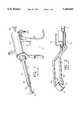
- FIG. 1shows a typical resectoscope 10 with an electrocautery probe 12.
- the resectoscope 10includes a distal guide tube 14 and a proximal handle 16.
- a telescope 18is inserted through the guide tube 14 and is provided with a proximal eye piece 20 for viewing the interior of the bladder or other operative site.
- the cautery probe 12has a distal electrode 22 which is mounted between a pair of arms 23, 25.
- the arms 23, 25are joined at their proximal ends to an electrode lead 27 which is coupled via the handle 16 to a wire 24 which is coupled to a source of cautery current (not shown).
- a mounting sleeve 29is provided on the probe 12 for slideably coupling it to the guide tube 14.
- the mounting sleeve 29is typically located at the point where the arms 23, 25 are joined to the electrode lead 27.
- the handle 16is generally capable of axially sliding the probe 12 and its distally mounted electrode 22 relative to the guide tube 14.
- the ablation or resection procedureinvolves applying a cauterizing voltage to the electrode 22 and moving the electrode slowly over the prostate or endometrium while viewing the tissue through the scope 18. Thermal energy is applied through the electrode to the prostate or the endometrium so that tissue is excised.
- the resectoscope and cautery probeare also useful in other procedures for resecting the uterus, ureter, or renal pelvis.
- Electrodes for use in resectoscopesare available in many different shapes and sizes.
- U.S. Pat. No. 4,917,082 to Grossi et al.discloses several embodiments of a "Resectoscope Electrode” including a coagulating electrode, a knife electrode, a punctate electrode, and a roller electrode, among others. Electrodes for use with resectoscopes are also widely available from Olsen Electrosurgical, Inc., Concord, Calif. They are available as blades, needles, balls, loops, spear tips, flexible wires, semi-circular wires, hooks, spatulas and blunt tips.
- roller baroften referred to as "roller bar” or “roller ball”
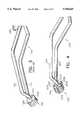
- FIGS. 1 and 2show a roller bar electrode 22.
- the roller baris approximately 2.5 mm long and has a central bore 22b. It is rotatably mounted between the arms 23, 25 at the distal end of the electrocautery probe 12 by means of an axle wire 21 which extends through the central bore 22b of the electrode 22.
- the roller baris supplied with a cauterizing voltage through the wire 21 which is coupled to the arms 23, 25 in the probe 12.
- the electrode 22When energized, the electrode 22 is rolled across the endometrial surface methodically until desired areas of the endometrium have been ablated.
- Roller bar electrodesare also used in prostatic resection. It is generally appreciated that in both endometrial ablation and prostatic resection, a larger surface area will allow the electrode to cover more tissue and thereby shorten the procedure. It is also understood that in the case of prostatic resection, the overall size of the electrode (as well as the resectoscope) must be kept to a minimum. Thus, it is difficult to increase the surface area of the electrode while maintaining a small overall size.
- One known way of providing increased electrode surface area while maintaining a small overall sizeis disclosed in co-owned U.S. Pat. No. 5,354,296 which describes a variable morphology electrode.
- FIG. 3shows an electrocautery probe 112 which is fitted with a roller electrode 122 having a helical groove 122a.
- the grooveeffectively increases the surface area of the electrode without increasing its overall size.
- the resulting roller electrodelacks traction and tends to glide over the tissue rather than rolling. This causes tissue to accumulate on the surface of the electrode and interfere with the surgical procedure.
- the electrocautery probe of the present inventionincludes a pair of arms between which a roller electrode is mounted.
- the armsare joined at their proximal ends to an electrode lead and a mounting sleeve is provided intermediate of the arms and the lead for slideably coupling the probe to a resectoscope.
- the roller electrodeis provided with a plurality of longitudinal surface grooves which increase surface area of the electrode and also enhance traction of the electrode.
- the groovespreferably have a depth of approximately 15-20% of the overall diameter of the roller electrode.
- the electrodeis provided with an eccentric concave or convex surface which increase the surface are of the electrode.
- the longitudinal groovesmay also be provided on electrodes having an eccentric surface thereby providing both increased traction and increased surface area.
- the electrodes according to the inventionare preferably made of copper, chromium cobalt, or carbonless stainless steel. They preferably have an overall diameter of from about 0.115 to about 0.187 inches and an overall length of from about 0.110 to about 0.120 inches. It has been discovered that the relatively sharp edges defined by the surface grooves also provide high heat zones for enhanced tissue vaporization.
- FIG. 1is perspective view of a prior art resectoscope with an electrocautery probe having a roller bar electrode;
- FIG. 2is an enlarged broken perspective view of the distal end of the prior art electrocautery probe of FIG. 1;
- FIG. 3is an enlarged broken perspective view of the distal end of another prior art electrocautery probe having a roller electrode with a helical surface groove;
- FIG. 4is a view similar to FIG. 3 of the distal end of an electrocautery probe having a roller electrode with longitudinal grooves according to a first embodiment of the invention
- FIG. 5is a view similar to FIG. 2 of an electrocautery probe having a roller electrode with longitudinal grooves according to a second embodiment of the invention
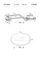
- FIG. 6is an enlarged side elevation view of a roller electrode with an eccentric surface according to a third embodiment of the invention.
- FIG. 7is an enlarged side elevation view of a roller electrode with an eccentric surface and longitudinal grooves according to a fourth embodiment of the invention.
- FIG. 8is an enlarged side elevation view of a roller electrode with an eccentric surface according to a fifth embodiment of the invention.
- FIG. 9is an enlarged side elevation view of a roller electrode with an eccentric surface and longitudinal grooves according to a sixth embodiment of the invention.
- an electrocautery probe 212includes an electrode 222 which is rotatably mounted between a pair of arms 223,225 at their distal ends.
- the proximal ends of the arms 223, 225are coupled to an electrode lead and a mounting sleeve (not shown) in a conventional manner.
- the electrode 222is a substantially cylindrical member having a helical surface groove 222a and a central axial bore 222b through which it is mounted to the arms 223, 225 in a conventional manner using an axle wire 221.
- the electrodemay be made of copper, chromium cobalt, or carbonless stainless steel. It has an overall diameter of approximately 0.115-0.187 inches and a length of approximately 0.110-0.120 inches.
- the axial bore 222bhas a diameter of approximately 0.020 inches and the axle wire 221 has a diameter of approximately 0.016 inches.
- a plurality of longitudinal surface grooves 221a-221dare provided on the outer surface of the electrode.
- the groovesare preferably approximately 0.020 inches deep, approximately 0.010 to 0.020 inches wide, and extend along substantially the entire length of the electrode.
- these grooves 221a-221dare spaced equidistantly about the electrode 222 and are substantially parallel to each other and to the rotational axis of the electrode. This arrangement places the longitudinal grooves 221a-221d substantially perpendicular to the helical groove 222a.
- the provided electrodehas improved traction as compared to the prior art electrode shown in FIG. 3.
- the added longitudinal grooves 221a-221dincrease the surface area of the electrode 222.
- the relatively sharp portions of the electrode 222 defined by the helical and longitudinal groovesserve as high heat zones for better tissue vaporization.
- the helical groove 222amay be replaced with a plurality of parallel radial grooves and that the longitudinal grooves need not be parallel to each other or to the rotational axis of the electrode.
- the helical groovehas a V-shaped section and the longitudinal grooves have U-shaped sections.
- the groovesmay have other shapes. While it is preferable that the longitudinal grooves extend along substantially the entire length of the electrode, it is sufficient that longitudinal grooves cross at least some of the radial grooves or at least a portion of the helical groove.
- FIG. 5a second embodiment of an electrode 322 according to the invention is shown mounted on the distal end of a probe 312.
- the probe 312is substantially the same as the probes 12, 112, and 212 described above, and similar reference numerals refer to similar parts of the probe.
- the electrode 322is a substantially cylindrical member having a relatively smooth surface 322a and an axial bore 322b.
- the outer surface of the electrode 322is provided with a plurality of longitudinal grooves 321a-321d.
- the electrode 322may be made of the same materials and the same or similar dimensions as the electrode 222 described above.
- the provided electrodehas increased traction due to the grooves 321a-321d and a somewhat increased surface area due to the grooves.
- the relatively sharp areas defined by the groovesprovide high heat zones for better tissue vaporization.
- FIG. 6a third embodiment of an electrode 422 is shown apart from a cautery probe.
- the electrode 422has a convex eccentric surface 422a which is either ovoid or ellipsoid, and a longitudinal bore 422b for mounting it on a cautery probe (not shown).
- the eccentric surface 422a of the electrode 422provides an increased surface area without dramatically increasing the overall size of the electrode.
- a fourth embodiment of an electrode 522has a substantially ovoid, ellipsoid or otherwise convex eccentric surface 522a and a longitudinal bore 522b for mounting it between arms of a probe (not shown) in a conventional manner.
- the outer surface of the electrode 522is provided with a plurality of longitudinal grooves 521a-521d.
- the electrode 522may be made of the same materials and the same or similar dimensions as the electrode 422 described above.
- the provided electrodehas increased surface area due in part to its eccentric surface and also due in part to the grooves. It will be appreciated that, the grooves provide added traction for the electrode when it is mounted for rotation at the distal end of a cautery probe. In addition, it will be understood that the grooves define relatively sharp edges which serve as high heat zones for better tissue vaporization.
- FIG. 8A fifth embodiment of the invention is shown in FIG. 8.
- the electrode 622 shown in FIG. 8has a concave eccentric surface 622a and resembles a spool.
- An axial bore 622bis provided for mounting the electrode between arms (not shown) in a conventional manner.
- the electrode 622may be made of the same materials and similar dimensions as the electrode 222 described above.
- the provided electrodehas an enlarged surface area and reduced mass. The electrode will therefore heat up faster.
- FIG. 9shows a sixth embodiment of the invention.
- the electrode 722 shown in FIG. 9is similar to the electrode 622 described above with a concave eccentric surface 722a and an axial bore 722b.
- the electrode 722is also provided with a plurality of longitudinal grooves 721a-721f.
- the groovesprovide increased traction to keep the electrode rolling when it is moved over tissue and also provide additional high heat zones as described above. From the foregoing, it will also be understood that it may be advantageous to place the grooves only at the extreme ends of the electrode, i.e. on the high points of the spool. This would be advantageous, for example, where the waist portion of the spool is too thin to be provided with a groove.
Landscapes
- Health & Medical Sciences (AREA)
- Surgery (AREA)
- Engineering & Computer Science (AREA)
- Life Sciences & Earth Sciences (AREA)
- Biomedical Technology (AREA)
- Molecular Biology (AREA)
- Nuclear Medicine, Radiotherapy & Molecular Imaging (AREA)
- Plasma & Fusion (AREA)
- Physics & Mathematics (AREA)
- Heart & Thoracic Surgery (AREA)
- Medical Informatics (AREA)
- Otolaryngology (AREA)
- Animal Behavior & Ethology (AREA)
- General Health & Medical Sciences (AREA)
- Public Health (AREA)
- Veterinary Medicine (AREA)
- Surgical Instruments (AREA)
- Endoscopes (AREA)
Abstract
Description
Claims (21)
Priority Applications (1)
| Application Number | Priority Date | Filing Date | Title |
|---|---|---|---|
| US08/425,367US5549605A (en) | 1995-04-20 | 1995-04-20 | Roller electrodes for electrocautery probes for use with a resectoscope |
Applications Claiming Priority (1)
| Application Number | Priority Date | Filing Date | Title |
|---|---|---|---|
| US08/425,367US5549605A (en) | 1995-04-20 | 1995-04-20 | Roller electrodes for electrocautery probes for use with a resectoscope |
Publications (1)
| Publication Number | Publication Date |
|---|---|
| US5549605Atrue US5549605A (en) | 1996-08-27 |
Family
ID=23686248
Family Applications (1)
| Application Number | Title | Priority Date | Filing Date |
|---|---|---|---|
| US08/425,367Expired - LifetimeUS5549605A (en) | 1995-04-20 | 1995-04-20 | Roller electrodes for electrocautery probes for use with a resectoscope |
Country Status (1)
| Country | Link |
|---|---|
| US (1) | US5549605A (en) |
Cited By (50)
| Publication number | Priority date | Publication date | Assignee | Title |
|---|---|---|---|---|
| WO1997017027A1 (en)* | 1995-11-08 | 1997-05-15 | Femrx, Inc. | Electrosurgical device having rollers for ablating and segmenting of tissues |
| WO1997034534A1 (en)* | 1996-03-18 | 1997-09-25 | Femrx, Inc. | Method and device for tissue vaporization and extraction |
| USD385351S (en)* | 1995-12-06 | 1997-10-21 | Northgate Technologies Incorporated | Tip portion of a resectoscope electrode |
| WO1997049346A1 (en)* | 1996-06-24 | 1997-12-31 | Karl Storz Gmbh & Co. | Smooth-surface rotary electrode for hf surgery |
| WO1998007377A1 (en)* | 1996-08-23 | 1998-02-26 | Nebl, Inc. | Electrode for coagulation and resection |
| US5746746A (en)* | 1996-08-30 | 1998-05-05 | Garito; Jon C. | Electrosurgical electrode and method for skin resurfacing |
| WO1998019612A1 (en) | 1996-11-05 | 1998-05-14 | Vandusseldorp Gregg A | Vaporizing roller for an electrosurgical probe |
| US5766215A (en)* | 1995-09-27 | 1998-06-16 | Endocare, Inc. | Electrosurgical loop providing enhanced tissue coagulation |
| US5766168A (en)* | 1996-01-11 | 1998-06-16 | Northgate Technologies, Inc. | Perforated resectoscope electrode assembly |
| US5782829A (en)* | 1995-12-06 | 1998-07-21 | Northgate Technologies Incorporated | Resectoscope electrode assembly and methods of use |
| US5827274A (en)* | 1995-07-18 | 1998-10-27 | Richard Wolf Gmbh | Electrode for vaporizing tissue |
| USD401338S (en) | 1996-06-18 | 1998-11-17 | Northgate Technologies, Inc. | Tip of a resectoscope electrode assembly design |
| US5925040A (en)* | 1997-06-18 | 1999-07-20 | Medical Scientific, Inc. | Electrosurgical instrument having a segmented roller electrode |
| US5935125A (en)* | 1996-04-17 | 1999-08-10 | Uros Corporation | Fulguration and cauterization device |
| US5944715A (en) | 1996-06-20 | 1999-08-31 | Gyrus Medical Limited | Electrosurgical instrument |
| US6004319A (en) | 1995-06-23 | 1999-12-21 | Gyrus Medical Limited | Electrosurgical instrument |
| US6013076A (en) | 1996-01-09 | 2000-01-11 | Gyrus Medical Limited | Electrosurgical instrument |
| US6015406A (en) | 1996-01-09 | 2000-01-18 | Gyrus Medical Limited | Electrosurgical instrument |
| US6027501A (en) | 1995-06-23 | 2000-02-22 | Gyrus Medical Limited | Electrosurgical instrument |
| US6032673A (en)* | 1994-10-13 | 2000-03-07 | Femrx, Inc. | Methods and devices for tissue removal |
| US6090106A (en) | 1996-01-09 | 2000-07-18 | Gyrus Medical Limited | Electrosurgical instrument |
| US6093186A (en) | 1996-12-20 | 2000-07-25 | Gyrus Medical Limited | Electrosurgical generator and system |
| US6152921A (en)* | 1995-12-22 | 2000-11-28 | Karl Storz Gmbh & Co. Kg | High frequency (HF) electrode for a HF instrument operating in monopolar mode |
| US6210405B1 (en) | 1996-06-20 | 2001-04-03 | Gyrus Medical Limited | Under water treatment |
| US6261286B1 (en) | 1995-06-23 | 2001-07-17 | Gyrus Medical Limited | Electrosurgical generator and system |
| US6277114B1 (en) | 1998-04-03 | 2001-08-21 | Gyrus Medical Limited | Electrode assembly for an electrosurical instrument |
| US6394949B1 (en) | 1998-10-05 | 2002-05-28 | Scimed Life Systems, Inc. | Large area thermal ablation |
| US6565561B1 (en) | 1996-06-20 | 2003-05-20 | Cyrus Medical Limited | Electrosurgical instrument |
| US20030130653A1 (en)* | 1997-09-30 | 2003-07-10 | Scimed Life Systems, Inc. | Electrosurgical tissue removal with a selectively insulated electrode |
| US20040030330A1 (en)* | 2002-04-18 | 2004-02-12 | Brassell James L. | Electrosurgery systems |
| US6780180B1 (en) | 1995-06-23 | 2004-08-24 | Gyrus Medical Limited | Electrosurgical instrument |
| US20040254571A1 (en)* | 2003-01-31 | 2004-12-16 | Kobi Iki | Cartilage treatment probe |
| US6997926B2 (en) | 2002-02-04 | 2006-02-14 | Boston Scientific Scimed, Inc. | Resistance heated tissue morcellation |
| USD569522S1 (en)* | 2004-08-24 | 2008-05-20 | Eli Eliachar | Roller bar electrode |
| US7481807B2 (en) | 2002-02-12 | 2009-01-27 | Oratec Interventions, Inc. | Radiofrequency arthroscopic ablation device |
| CN100457054C (en)* | 2007-03-19 | 2009-02-04 | 孙茂莲 | Forceps for removing submucous myoma of uterus |
| US20090247823A1 (en)* | 2005-09-26 | 2009-10-01 | Hironori Yamamoto | Instrument for Endoscopic Treatment |
| US20090281534A1 (en)* | 2007-05-11 | 2009-11-12 | Prinz Friedrich B | System for delivering therapy |
| US7867163B2 (en) | 1998-06-22 | 2011-01-11 | Maquet Cardiovascular Llc | Instrument and method for remotely manipulating a tissue structure |
| US7938842B1 (en) | 1998-08-12 | 2011-05-10 | Maquet Cardiovascular Llc | Tissue dissector apparatus |
| US7972265B1 (en) | 1998-06-22 | 2011-07-05 | Maquet Cardiovascular, Llc | Device and method for remote vessel ligation |
| US7981133B2 (en) | 1995-07-13 | 2011-07-19 | Maquet Cardiovascular, Llc | Tissue dissection method |
| US8066700B2 (en)* | 2003-01-31 | 2011-11-29 | Smith & Nephew, Inc. | Cartilage treatment probe |
| US20120059219A1 (en)* | 2009-06-30 | 2012-03-08 | Gyrus Acmi, Inc. | Bipolar resection device having simplified rotational control and better visualization |
| US8241210B2 (en) | 1998-06-22 | 2012-08-14 | Maquet Cardiovascular Llc | Vessel retractor |
| WO2012175912A1 (en) | 2011-06-23 | 2012-12-27 | Gyrus Medical Limited | Electrosurgical electrode |
| DE102014212102A1 (en) | 2013-06-24 | 2014-12-24 | Gyrus Medical Ltd. | Electrosurgical electrode |
| US10299770B2 (en) | 2006-06-01 | 2019-05-28 | Maquet Cardiovascular Llc | Endoscopic vessel harvesting system components |
| CN110151306A (en)* | 2019-05-17 | 2019-08-23 | 杭州睿笛生物科技有限公司 | An electric pulse parallel electrode |
| US10507012B2 (en) | 2000-11-17 | 2019-12-17 | Maquet Cardiovascular Llc | Vein harvesting system and method |
Citations (11)
| Publication number | Priority date | Publication date | Assignee | Title |
|---|---|---|---|---|
| US1971024A (en)* | 1932-01-25 | 1934-08-21 | Wappler Frederick Charles | Instrument for electrosurgical resection |
| US2487502A (en)* | 1945-09-26 | 1949-11-08 | American Cystoscope Makers Inc | Instrument for electrosurgical resection |
| US2815757A (en)* | 1956-01-18 | 1957-12-10 | Elmer A Piar | Medical electrode |
| US3752159A (en)* | 1971-05-03 | 1973-08-14 | American Cystoscope Makers Inc | Resectoscope cutting electrode |
| WO1981003271A1 (en)* | 1980-05-13 | 1981-11-26 | American Hospital Supply Corp | A multipolar electrosurgical device |
| US4917082A (en)* | 1988-06-02 | 1990-04-17 | Circon Corporation | Resectoscope electrode |
| US5196011A (en)* | 1990-10-15 | 1993-03-23 | Olympus Winter & Ibe Gmbh | Cutting electrode for medical resectoscope |
| US5324288A (en)* | 1991-04-30 | 1994-06-28 | Utah Medical Products, Inc. | Electrosurgical loop with a depth gauge |
| US5354296A (en)* | 1993-03-24 | 1994-10-11 | Symbiosis Corporation | Electrocautery probe with variable morphology electrode |
| US5395363A (en)* | 1993-06-29 | 1995-03-07 | Utah Medical Products | Diathermy coagulation and ablation apparatus and method |
| US5395312A (en)* | 1991-10-18 | 1995-03-07 | Desai; Ashvin | Surgical tool |
- 1995
- 1995-04-20USUS08/425,367patent/US5549605A/ennot_activeExpired - Lifetime
Patent Citations (12)
| Publication number | Priority date | Publication date | Assignee | Title |
|---|---|---|---|---|
| US1971024A (en)* | 1932-01-25 | 1934-08-21 | Wappler Frederick Charles | Instrument for electrosurgical resection |
| US2487502A (en)* | 1945-09-26 | 1949-11-08 | American Cystoscope Makers Inc | Instrument for electrosurgical resection |
| US2815757A (en)* | 1956-01-18 | 1957-12-10 | Elmer A Piar | Medical electrode |
| US3752159A (en)* | 1971-05-03 | 1973-08-14 | American Cystoscope Makers Inc | Resectoscope cutting electrode |
| US3752159B1 (en)* | 1971-05-03 | 1984-07-17 | ||
| WO1981003271A1 (en)* | 1980-05-13 | 1981-11-26 | American Hospital Supply Corp | A multipolar electrosurgical device |
| US4917082A (en)* | 1988-06-02 | 1990-04-17 | Circon Corporation | Resectoscope electrode |
| US5196011A (en)* | 1990-10-15 | 1993-03-23 | Olympus Winter & Ibe Gmbh | Cutting electrode for medical resectoscope |
| US5324288A (en)* | 1991-04-30 | 1994-06-28 | Utah Medical Products, Inc. | Electrosurgical loop with a depth gauge |
| US5395312A (en)* | 1991-10-18 | 1995-03-07 | Desai; Ashvin | Surgical tool |
| US5354296A (en)* | 1993-03-24 | 1994-10-11 | Symbiosis Corporation | Electrocautery probe with variable morphology electrode |
| US5395363A (en)* | 1993-06-29 | 1995-03-07 | Utah Medical Products | Diathermy coagulation and ablation apparatus and method |
Cited By (79)
| Publication number | Priority date | Publication date | Assignee | Title |
|---|---|---|---|---|
| US6032673A (en)* | 1994-10-13 | 2000-03-07 | Femrx, Inc. | Methods and devices for tissue removal |
| US6174308B1 (en) | 1995-06-23 | 2001-01-16 | Gyrus Medical Limited | Electrosurgical instrument |
| US6056746A (en) | 1995-06-23 | 2000-05-02 | Gyrus Medical Limited | Electrosurgical instrument |
| US6780180B1 (en) | 1995-06-23 | 2004-08-24 | Gyrus Medical Limited | Electrosurgical instrument |
| US6027501A (en) | 1995-06-23 | 2000-02-22 | Gyrus Medical Limited | Electrosurgical instrument |
| US6416509B1 (en) | 1995-06-23 | 2002-07-09 | Gyrus Medical Limited | Electrosurgical generator and system |
| US6364877B1 (en) | 1995-06-23 | 2002-04-02 | Gyrus Medical Limited | Electrosurgical generator and system |
| US6306134B1 (en) | 1995-06-23 | 2001-10-23 | Gyrus Medical Limited | Electrosurgical generator and system |
| US6004319A (en) | 1995-06-23 | 1999-12-21 | Gyrus Medical Limited | Electrosurgical instrument |
| US6261286B1 (en) | 1995-06-23 | 2001-07-17 | Gyrus Medical Limited | Electrosurgical generator and system |
| US6293942B1 (en) | 1995-06-23 | 2001-09-25 | Gyrus Medical Limited | Electrosurgical generator method |
| US7981133B2 (en) | 1995-07-13 | 2011-07-19 | Maquet Cardiovascular, Llc | Tissue dissection method |
| US5827274A (en)* | 1995-07-18 | 1998-10-27 | Richard Wolf Gmbh | Electrode for vaporizing tissue |
| US5766215A (en)* | 1995-09-27 | 1998-06-16 | Endocare, Inc. | Electrosurgical loop providing enhanced tissue coagulation |
| WO1997017027A1 (en)* | 1995-11-08 | 1997-05-15 | Femrx, Inc. | Electrosurgical device having rollers for ablating and segmenting of tissues |
| US5782829A (en)* | 1995-12-06 | 1998-07-21 | Northgate Technologies Incorporated | Resectoscope electrode assembly and methods of use |
| USD385351S (en)* | 1995-12-06 | 1997-10-21 | Northgate Technologies Incorporated | Tip portion of a resectoscope electrode |
| US6152921A (en)* | 1995-12-22 | 2000-11-28 | Karl Storz Gmbh & Co. Kg | High frequency (HF) electrode for a HF instrument operating in monopolar mode |
| US6090106A (en) | 1996-01-09 | 2000-07-18 | Gyrus Medical Limited | Electrosurgical instrument |
| US6234178B1 (en) | 1996-01-09 | 2001-05-22 | Gyrus Medical Limited | Electrosurgical instrument |
| US6013076A (en) | 1996-01-09 | 2000-01-11 | Gyrus Medical Limited | Electrosurgical instrument |
| US6015406A (en) | 1996-01-09 | 2000-01-18 | Gyrus Medical Limited | Electrosurgical instrument |
| US5766168A (en)* | 1996-01-11 | 1998-06-16 | Northgate Technologies, Inc. | Perforated resectoscope electrode assembly |
| WO1997034534A1 (en)* | 1996-03-18 | 1997-09-25 | Femrx, Inc. | Method and device for tissue vaporization and extraction |
| US5935125A (en)* | 1996-04-17 | 1999-08-10 | Uros Corporation | Fulguration and cauterization device |
| USD401338S (en) | 1996-06-18 | 1998-11-17 | Northgate Technologies, Inc. | Tip of a resectoscope electrode assembly design |
| US6565561B1 (en) | 1996-06-20 | 2003-05-20 | Cyrus Medical Limited | Electrosurgical instrument |
| US6482202B1 (en) | 1996-06-20 | 2002-11-19 | Gyrus Medical Limited | Under water treatment |
| US5944715A (en) | 1996-06-20 | 1999-08-31 | Gyrus Medical Limited | Electrosurgical instrument |
| US6210405B1 (en) | 1996-06-20 | 2001-04-03 | Gyrus Medical Limited | Under water treatment |
| WO1997049346A1 (en)* | 1996-06-24 | 1997-12-31 | Karl Storz Gmbh & Co. | Smooth-surface rotary electrode for hf surgery |
| US6251108B1 (en)* | 1996-06-24 | 2001-06-26 | Karl Storz Gmbh & Co. Kg | Smooth-surface rotary electrode for HF surgery |
| US5749870A (en)* | 1996-08-23 | 1998-05-12 | Nebl, Inc. | Electrode for coagulation and resection |
| WO1998007377A1 (en)* | 1996-08-23 | 1998-02-26 | Nebl, Inc. | Electrode for coagulation and resection |
| US5746746A (en)* | 1996-08-30 | 1998-05-05 | Garito; Jon C. | Electrosurgical electrode and method for skin resurfacing |
| US5759183A (en)* | 1996-11-05 | 1998-06-02 | Vandusseldorp; Gregg A. | Vaporizing roller for an electrosurgical probe |
| WO1998019612A1 (en) | 1996-11-05 | 1998-05-14 | Vandusseldorp Gregg A | Vaporizing roller for an electrosurgical probe |
| US6093186A (en) | 1996-12-20 | 2000-07-25 | Gyrus Medical Limited | Electrosurgical generator and system |
| US5925040A (en)* | 1997-06-18 | 1999-07-20 | Medical Scientific, Inc. | Electrosurgical instrument having a segmented roller electrode |
| US20030130653A1 (en)* | 1997-09-30 | 2003-07-10 | Scimed Life Systems, Inc. | Electrosurgical tissue removal with a selectively insulated electrode |
| US6277114B1 (en) | 1998-04-03 | 2001-08-21 | Gyrus Medical Limited | Electrode assembly for an electrosurical instrument |
| US8241210B2 (en) | 1998-06-22 | 2012-08-14 | Maquet Cardiovascular Llc | Vessel retractor |
| US7972265B1 (en) | 1998-06-22 | 2011-07-05 | Maquet Cardiovascular, Llc | Device and method for remote vessel ligation |
| US7867163B2 (en) | 1998-06-22 | 2011-01-11 | Maquet Cardiovascular Llc | Instrument and method for remotely manipulating a tissue structure |
| US7938842B1 (en) | 1998-08-12 | 2011-05-10 | Maquet Cardiovascular Llc | Tissue dissector apparatus |
| US8460331B2 (en) | 1998-08-12 | 2013-06-11 | Maquet Cardiovascular, Llc | Tissue dissector apparatus and method |
| US8986335B2 (en) | 1998-08-12 | 2015-03-24 | Maquet Cardiovascular Llc | Tissue dissector apparatus and method |
| US9730782B2 (en) | 1998-08-12 | 2017-08-15 | Maquet Cardiovascular Llc | Vessel harvester |
| US9700398B2 (en) | 1998-08-12 | 2017-07-11 | Maquet Cardiovascular Llc | Vessel harvester |
| US6394949B1 (en) | 1998-10-05 | 2002-05-28 | Scimed Life Systems, Inc. | Large area thermal ablation |
| US7749159B2 (en) | 1998-10-05 | 2010-07-06 | Boston Scientific Scimed, Inc. | Large area thermal ablation |
| US20100256632A1 (en)* | 1998-10-05 | 2010-10-07 | Boston Scientific Scimed, Inc. | Large area thermal ablation |
| US20060020264A1 (en)* | 1998-10-05 | 2006-01-26 | Boston Scientific Scimed, Inc. | Large area thermal ablation |
| US6932812B2 (en) | 1998-10-05 | 2005-08-23 | Scimed Life Systems, Inc. | Large area thermal ablation |
| US10507012B2 (en) | 2000-11-17 | 2019-12-17 | Maquet Cardiovascular Llc | Vein harvesting system and method |
| US6997926B2 (en) | 2002-02-04 | 2006-02-14 | Boston Scientific Scimed, Inc. | Resistance heated tissue morcellation |
| US7481807B2 (en) | 2002-02-12 | 2009-01-27 | Oratec Interventions, Inc. | Radiofrequency arthroscopic ablation device |
| US20040030330A1 (en)* | 2002-04-18 | 2004-02-12 | Brassell James L. | Electrosurgery systems |
| US20040254571A1 (en)* | 2003-01-31 | 2004-12-16 | Kobi Iki | Cartilage treatment probe |
| US20110230879A1 (en)* | 2003-01-31 | 2011-09-22 | Smith & Nephew, Inc. | Cartilage treatment probe |
| US8066700B2 (en)* | 2003-01-31 | 2011-11-29 | Smith & Nephew, Inc. | Cartilage treatment probe |
| US7951142B2 (en)* | 2003-01-31 | 2011-05-31 | Smith & Nephew, Inc. | Cartilage treatment probe |
| US8500734B2 (en) | 2003-01-31 | 2013-08-06 | Smith & Nephew, Inc. | Cartilage treatment probe |
| US8377058B2 (en) | 2003-01-31 | 2013-02-19 | Smith & Nephew, Inc. | Cartilage treatment probe |
| USD569522S1 (en)* | 2004-08-24 | 2008-05-20 | Eli Eliachar | Roller bar electrode |
| US9220560B2 (en)* | 2005-09-26 | 2015-12-29 | Jichi Medical University | Instrument for endoscopic treatment |
| US20090247823A1 (en)* | 2005-09-26 | 2009-10-01 | Hironori Yamamoto | Instrument for Endoscopic Treatment |
| EP2572666B1 (en)* | 2005-09-26 | 2018-11-07 | Jichi Medical University | Instrument for endoscopic treatment |
| US11141055B2 (en) | 2006-06-01 | 2021-10-12 | Maquet Cardiovascular Llc | Endoscopic vessel harvesting system components |
| US11134835B2 (en) | 2006-06-01 | 2021-10-05 | Maquet Cardiovascular Llc | Endoscopic vessel harvesting system components |
| US10299770B2 (en) | 2006-06-01 | 2019-05-28 | Maquet Cardiovascular Llc | Endoscopic vessel harvesting system components |
| CN100457054C (en)* | 2007-03-19 | 2009-02-04 | 孙茂莲 | Forceps for removing submucous myoma of uterus |
| US8100900B2 (en)* | 2007-05-11 | 2012-01-24 | Board Of Trustees Of The Leland Stanford Junior University | System for delivering therapy |
| US20090281534A1 (en)* | 2007-05-11 | 2009-11-12 | Prinz Friedrich B | System for delivering therapy |
| US20120059219A1 (en)* | 2009-06-30 | 2012-03-08 | Gyrus Acmi, Inc. | Bipolar resection device having simplified rotational control and better visualization |
| US9414886B2 (en) | 2011-06-23 | 2016-08-16 | Gyrus Medical Limited | Electrosurgical electrode |
| WO2012175912A1 (en) | 2011-06-23 | 2012-12-27 | Gyrus Medical Limited | Electrosurgical electrode |
| DE102014212102A1 (en) | 2013-06-24 | 2014-12-24 | Gyrus Medical Ltd. | Electrosurgical electrode |
| CN110151306A (en)* | 2019-05-17 | 2019-08-23 | 杭州睿笛生物科技有限公司 | An electric pulse parallel electrode |
Similar Documents
| Publication | Publication Date | Title |
|---|---|---|
| US5549605A (en) | Roller electrodes for electrocautery probes for use with a resectoscope | |
| US5569244A (en) | Loop electrodes for electrocautery probes for use with a resectoscope | |
| US5938661A (en) | Single arm electrocautery probes for use with a resectoscope | |
| US5957923A (en) | Loop electrodes for electrocautery probes for use with a resectoscope | |
| US5906615A (en) | Serpentine ablation/coagulation electrode | |
| US5192280A (en) | Pivoting multiple loop bipolar cutting device | |
| EP0930847B1 (en) | Apparatus for thermal treatment of tissue | |
| US5980519A (en) | Electrocautery probe with variable morphology electrode | |
| US6673071B2 (en) | Partial ablation procedure and device therefor | |
| US5250047A (en) | Bipolar laparoscopic instrument with replaceable electrode tip assembly | |
| US6106521A (en) | Apparatus for thermal treatment of tissue | |
| EP1330989B1 (en) | An electrosurgical instrument | |
| US9066724B2 (en) | Surgical instrument | |
| US20090254082A1 (en) | Electrosurgical instrument | |
| JP2001504000A (en) | Coagulation and resection electrodes | |
| US6852111B1 (en) | Laparoscopic electrotome | |
| JP2000506405A (en) | Underwater electrosurgical instrument | |
| US5902300A (en) | Electrodes having upper and lower operating surfaces for electrocautery probes for use with a resectoscope | |
| JP2001128987A (en) | Articulated-movable ionizable gas coagulation instrument | |
| US5779700A (en) | Roller electrodes for electrocautery probes for use with a resectroscope | |
| US5908419A (en) | Resectoscope roller electrode having high heat zone insert | |
| EP1072230A1 (en) | A bipolar ablation/coagulation electrode | |
| WO1998033445A1 (en) | Single arm electrocautery probes and probes with upper and lower operating surfaces for use with a resectoscope | |
| WO1998033445A9 (en) | Single arm electrocautery probes and probes with upper and lower operating surfaces for use with a resectoscope | |
| US20090093808A1 (en) | Partial (non-apical) prostate ablation procedure and device |
Legal Events
| Date | Code | Title | Description |
|---|---|---|---|
| AS | Assignment | Owner name:SYMBIOSIS CORPORATION, FLORIDA Free format text:ASSIGNMENT OF ASSIGNORS INTEREST;ASSIGNOR:HAHNEN, KEVIN F.;REEL/FRAME:007610/0762 Effective date:19950419 | |
| STCF | Information on status: patent grant | Free format text:PATENTED CASE | |
| FEPP | Fee payment procedure | Free format text:PAYOR NUMBER ASSIGNED (ORIGINAL EVENT CODE: ASPN); ENTITY STATUS OF PATENT OWNER: LARGE ENTITY | |
| AS | Assignment | Owner name:CIRCON CORPORATION, CALIFORNIA Free format text:ASSIGNMENT OF ASSIGNORS INTEREST;ASSIGNOR:BOSTON SCIENTIFIC CORPORATION THROUGH ITS WHOLLY OWNED SUBSIDIARY SYMBIOSIS CORPORATION;REEL/FRAME:009638/0619 Effective date:19980929 | |
| DC | Disclaimer filed | Effective date:19990119 | |
| FPAY | Fee payment | Year of fee payment:4 | |
| AS | Assignment | Owner name:CHASE MANHATTAN BANK, THE, AS COLLATERAL AGENT, NE Free format text:SECURITY AGREEMENT;ASSIGNOR:CIRCON CORPORATION;REEL/FRAME:011122/0530 Effective date:19991112 | |
| AS | Assignment | Owner name:ACMI CORPORATION, MASSACHUSETTS Free format text:CHANGE OF NAME;ASSIGNOR:CIRCON CORPORATION;REEL/FRAME:013295/0416 Effective date:20011227 | |
| AS | Assignment | Owner name:ANTARES CAPITAL CORPORATION, AS AGENT, ILLINOIS Free format text:SECURITY INTEREST;ASSIGNOR:ACMI CORPORATION;REEL/FRAME:014815/0179 Effective date:20031219 Owner name:CIRCON CORPORATION, MASSACHUSETTS Free format text:RELEASE BY SECURED PARTY;ASSIGNOR:JPMORGAN CHASE BANK, AS COLLATERAL AGENT (F/K/A THE CHASE MANHATTAN BANK);REEL/FRAME:015592/0392 Effective date:20031219 | |
| FPAY | Fee payment | Year of fee payment:8 | |
| AS | Assignment | Owner name:ACMI CORPORATION, MASSACHUSETTS Free format text:RELASE OF SECURITY AGREEMENT;ASSIGNOR:ANTARES CAPITAL CORPORATION;REEL/FRAME:016309/0574 Effective date:20050721 | |
| AS | Assignment | Owner name:THE GOVERNOR AND COMPANY OF THE BANK OF SCOTLAND, Free format text:SECURITY AGREEMENT;ASSIGNOR:ACMI CORPORATION;REEL/FRAME:016418/0218 Effective date:20050804 | |
| FPAY | Fee payment | Year of fee payment:12 | |
| AS | Assignment | Owner name:GYRUS ACMI, INC., MASSACHUSETTS Free format text:CHANGE OF NAME;ASSIGNOR:ACMI CORPORATION;REEL/FRAME:024755/0110 Effective date:20070110 | |
| AS | Assignment | Owner name:GYRUS ACMI, INC., MASSACHUSETTS Free format text:ASSIGNMENT OF ASSIGNORS INTEREST;ASSIGNOR:BANK OF SCOTLAND;REEL/FRAME:030422/0113 Effective date:20130419 |