US5549558A - Self sheathing safety needle - Google Patents
Self sheathing safety needleDownload PDFInfo
- Publication number
- US5549558A US5549558AUS08/488,516US48851695AUS5549558AUS 5549558 AUS5549558 AUS 5549558AUS 48851695 AUS48851695 AUS 48851695AUS 5549558 AUS5549558 AUS 5549558A
- Authority
- US
- United States
- Prior art keywords
- needle
- needle guard
- guard member
- casing
- self
- Prior art date
- Legal status (The legal status is an assumption and is not a legal conclusion. Google has not performed a legal analysis and makes no representation as to the accuracy of the status listed.)
- Expired - Lifetime
Links
Images


Classifications
- A—HUMAN NECESSITIES
- A61—MEDICAL OR VETERINARY SCIENCE; HYGIENE
- A61M—DEVICES FOR INTRODUCING MEDIA INTO, OR ONTO, THE BODY; DEVICES FOR TRANSDUCING BODY MEDIA OR FOR TAKING MEDIA FROM THE BODY; DEVICES FOR PRODUCING OR ENDING SLEEP OR STUPOR
- A61M5/00—Devices for bringing media into the body in a subcutaneous, intra-vascular or intramuscular way; Accessories therefor, e.g. filling or cleaning devices, arm-rests
- A61M5/178—Syringes
- A61M5/31—Details
- A61M5/32—Needles; Details of needles pertaining to their connection with syringe or hub; Accessories for bringing the needle into, or holding the needle on, the body; Devices for protection of needles
- A61M5/3205—Apparatus for removing or disposing of used needles or syringes, e.g. containers; Means for protection against accidental injuries from used needles
- A61M5/321—Means for protection against accidental injuries by used needles
- A61M5/3243—Means for protection against accidental injuries by used needles being axially-extensible, e.g. protective sleeves coaxially slidable on the syringe barrel
- A61M5/3271—Means for protection against accidental injuries by used needles being axially-extensible, e.g. protective sleeves coaxially slidable on the syringe barrel with guiding tracks for controlled sliding of needle protective sleeve from needle exposing to needle covering position
- A—HUMAN NECESSITIES
- A61—MEDICAL OR VETERINARY SCIENCE; HYGIENE
- A61M—DEVICES FOR INTRODUCING MEDIA INTO, OR ONTO, THE BODY; DEVICES FOR TRANSDUCING BODY MEDIA OR FOR TAKING MEDIA FROM THE BODY; DEVICES FOR PRODUCING OR ENDING SLEEP OR STUPOR
- A61M5/00—Devices for bringing media into the body in a subcutaneous, intra-vascular or intramuscular way; Accessories therefor, e.g. filling or cleaning devices, arm-rests
- A61M5/178—Syringes
- A61M5/31—Details
- A61M5/32—Needles; Details of needles pertaining to their connection with syringe or hub; Accessories for bringing the needle into, or holding the needle on, the body; Devices for protection of needles
- A61M5/3205—Apparatus for removing or disposing of used needles or syringes, e.g. containers; Means for protection against accidental injuries from used needles
- A61M5/321—Means for protection against accidental injuries by used needles
- A61M5/3243—Means for protection against accidental injuries by used needles being axially-extensible, e.g. protective sleeves coaxially slidable on the syringe barrel
- A61M5/326—Fully automatic sleeve extension, i.e. in which triggering of the sleeve does not require a deliberate action by the user
- A61M2005/3267—Biased sleeves where the needle is uncovered by insertion of the needle into a patient's body
- A—HUMAN NECESSITIES
- A61—MEDICAL OR VETERINARY SCIENCE; HYGIENE
- A61M—DEVICES FOR INTRODUCING MEDIA INTO, OR ONTO, THE BODY; DEVICES FOR TRANSDUCING BODY MEDIA OR FOR TAKING MEDIA FROM THE BODY; DEVICES FOR PRODUCING OR ENDING SLEEP OR STUPOR
- A61M5/00—Devices for bringing media into the body in a subcutaneous, intra-vascular or intramuscular way; Accessories therefor, e.g. filling or cleaning devices, arm-rests
- A61M5/178—Syringes
- A61M5/31—Details
- A61M5/32—Needles; Details of needles pertaining to their connection with syringe or hub; Accessories for bringing the needle into, or holding the needle on, the body; Devices for protection of needles
- A61M5/3205—Apparatus for removing or disposing of used needles or syringes, e.g. containers; Means for protection against accidental injuries from used needles
- A61M5/321—Means for protection against accidental injuries by used needles
- A61M5/3243—Means for protection against accidental injuries by used needles being axially-extensible, e.g. protective sleeves coaxially slidable on the syringe barrel
- A61M5/3271—Means for protection against accidental injuries by used needles being axially-extensible, e.g. protective sleeves coaxially slidable on the syringe barrel with guiding tracks for controlled sliding of needle protective sleeve from needle exposing to needle covering position
- A61M5/3272—Means for protection against accidental injuries by used needles being axially-extensible, e.g. protective sleeves coaxially slidable on the syringe barrel with guiding tracks for controlled sliding of needle protective sleeve from needle exposing to needle covering position having projections following labyrinth paths
Definitions
- This inventionrelates to medical equipment, and more specifically to safety needle devices for the injection or aspiration of a fluid.
- U.S. Pat. No. 4,813,940 dated Mar. 21, 1989shows an injection device in which a pair of telescoping sleeve members receive a needle with an inner sleeve member covering the needle in an extended position.
- the inner sleeve memberis manually rotated for movement from a locked position preventing retraction of the sleeve member, and an unlocked position permitting retraction of the sleeve member for injection or aspiration of a fluid from the needle.
- the outer sleeve member or housingis secured to an inner member in which the base of a needle is press fitted.
- the present inventionis directed particularly to a self sheathing needle in which an inner needle guard member or sheath is mounted in telescoping relation within an outer casing member for relative rotation between an extended locked position of the needle guard member and an extended unlocked position of the needle guard member.
- the sheathIn the unlocked position of the needle guard member or sheath, the sheath may be moved to a retracted position by contact with a patient or object upon injection or aspiration of a fluid by the needle.
- the needlemay be used more than once to permit first the drawing of the medication for injection, and then performing the injection procedure.
- the outer casing memberreceives the inner needle guard member which is continuously urged to an extended position, and coacting guide means on the casing member and the needle guard member guide the needle guard member to an unlocked position upon manual rotation of the outer casing member.
- the guide means on the needle guard memberincludes a resilient spring finger having a locking tab on the extending free end of the spring finger. The locking tab is cammed radially by a ramp on the casing member for movement between locked and unlocked positions.
- a needle assemblyincludes the hollow needle and a base for the needle. Additional coacting guide means on the base and the needle guard member operably connect the base and needle guard member for relative longitudinal sliding movement of the needle guard member while blocking relative rotational movement between the base and the needle guard member.
- the baseincludes a hub portion which has an outer arcuate bearing supporting the casing member for rotative movement upon manual rotation of the casing member. Stops are provided adjacent the bearing for limiting the rotation of the casing member at the extended locked position and the extended unlocked position of the needle guard member. Thus, separate stop means for blocking rotation of the casing member past the locked and unlocked extended positions of the needle guard member are provided to supplement the blocking by the locking tab. Such an arrangement provides a safety feature in the event of failure of a locking tab.
- a compression springconstantly urges the needle guard member to an extended position. This results in the needle guard member always being in contact with the human patient or other object being injected, while the needle device is in actual operation. Thus, the sharp needle point is never exposed to the outside during use of the self sheathing needle thereof preventing accidental needle sticks or pricks.
- the embodiment illustrated in the drawingsis designed to be used with any type hypodermic syringe device, or any other device with a conventional luer lock fitting which may be used for introducing fluid into a human body or extracting any fluid or other material from a human body, during medical procedures in the health care setting, or similar procedures in the veterinary setting.
- the present inventionmay be utilized with a friction fit design such as would be used on the end of an insulin syringe, or other friction fit type syringe or device, in which the needle is installed with a friction fit.
- the present inventionmay be utilized in a blood collecting design, to be used with conventional blood collection systems that utilize a double sided blood collection needle with a threaded attachment to a blood collection needle holder.
- any of the various embodimentsmay be pre-installed with the hypodermic syringe or other device, or it may be installed manually prior to use by the medical worker.
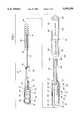
- FIG. 1is an isometric exploded view of the self sheathing needle comprising the present invention
- FIG. 2is an enlarged isometric view of the needle assembly of the invention shown in FIG. 1;
- FIG. 3is an enlarged isometric view of the needle guard member of the invention shown in FIG. 1;
- FIG. 4is an enlarged isometric cutaway view of the casing member of my self sheathing needle shown in FIG. 1;
- FIG. 5is a schematic view of the locking tab track, and locking tab illustrating the different positions of the locking tab during operation
- FIG. 6is an isometric view with certain parts broken away of the assembled self sheathing needle shown in FIG. 1;
- FIG. 7is a plan view illustrating the connection of a luer lock syringe to the self sheathing needle of the present invention.
- FIG. 8is a front plan view of the needle guard member shown in FIG. 1;
- FIG. 9Ais an end view of the casing member and needle assembly
- FIG. 9Bis an end view of the casing member and needle guard member illustrating the locking tab immediately prior to engaging the ramp for moving to a locked position
- FIG. 9Cis an end view of the casing member and needle guard member similar to FIG. 9B but showing the locking tab in a locked position behind the ramp.
- the self sheathing needle of this inventioncomprises a needle assembly 50, a compression spring 56, a needle guard member 52, and a casing member 54.
- Needle assembly 50is shown in an enlarged view in FIG. 2.
- needle assembly 50comprises a hollow tapered needle hub or base 86, a rectangularly shaped sliding bar portion 66 secured to hub 86, and a hollow needle 72 having a hollow sharp needle point 70.
- Needle or needle shaft 72can be made of any desired length, size, or gauge, generally out of a suitable metal, such as stainless steel.
- the remainder of needle assembly 50can be made of any suitable plastic, common to disposable syringes, which is able to tolerate standard sterilization treatment prior to distribution.
- Needle assembly 50can also be made of any other suitable materials, such as stainless steel or other metals when used in veterinary practices, or working with laboratory animals, where using a needle on multiple subjects is permissible. Any material that will fit the properties needed may be used.
- Hub 86is hollow, and is of a tapered tubular shape to receive the male connector portion of the conventional luer lock syringe 85 as shown in FIG. 7, in a sealing frictional engagement.
- arcuate rotational bearings 60 and 62Spaced longitudinally on the outside surface of hub 86 are arcuate rotational bearings 60 and 62.
- stops 80 and 82At the ends of bearing 60 are two opposing rotational safety stops 80 and 82 having flat surfaces.
- the surfaces of stops 80 and 82form an inclined acute angle with the outer surface of hub 86. This inclined angle matches the angle at which stops 80 and 82 engage a rotational safety stop bar 202 at a pair of surfaces 204 and 206, as casing or casing member 54 rotates on bearings 60 and 62 as shown particularly in FIGS. 4 and 6.
- stops 80 and 82Because of the inclined surfaces of stops 80 and 82, and the matching inclined surfaces 204 and 206 of stop bar 202; the harder that casing 54 is twisted either clockwise or counterclockwise, the tighter safety stops 80 and 82 are pushed into the angles formed at the junction of stop bar 202 with casing 54. This gives the entire assembly exceptional strength and stability against strong rotational forces which may be exerted while attaching my self sheathing needle to a conventional luer lock syringe.
- Bearing 62 at the end of hub 86is also provided with a pair of rotational safety stops 76 and 78, which are formed in similar fashion to stops 80 and 82, one stop being at each end of bearing 62. Stops 76 and 78 also are formed at inclined acute angles, and are matching with the inclined surfaces of stop bar 202 at safety stop surfaces 142 and 198. Second bearing 62 is not essential to my self sheathing needle, but will make it stronger and more stable when used.
- the bottom inside surface of hub 86has a small hole 77 as shown in FIG. 2 which is formed integrally with the inner end of hollow needle shaft 72.
- the inner end of hub 86defines a planar surface 63 and rectangular sliding bar 66 is fixedly attached to surface 63.
- a rectangular reinforcing strip 64is integrally connected to each side of sliding bar 66 and surface 63 for reinforcing sliding bar 66.
- Sliding bar 66fits within a rectangular groove 112 formed within needle guard 52. Sliding bar 66 engages groove 112 in a sliding telescopic in and out motion, and prevents needle guard 52 from rotating, but maintains needle assembly 50 in coaxial alignment with needle guard 52 at all times.
- a locking tab memory lever or spring finger 98also has a slight down and up movement during use, which will be more fully explained hereafter.
- Needle shaft 72is made of any desired length, so long as needle point 70 does not protrude from the end of needle guard 52 at an opening 106. Needle shaft 72 can also be made of any gauge or thickness, so long as it slides easily within a needle guard shaft circular lumen 108, contained in a needle guard tubular nose portion 102. Lumen 108 is also sized to receive needle shaft 72 according to the size of needle shaft 72. Hollow needle point 70 is sharp to penetrate a patient's skin for injection of a fluid medication or aspiration of a body substance. Needle point 70 is typical of conventional hypodermic syringe needles.
- a compression spring 56shown in FIGS. 1 and 6.
- the length and diameter of spring 56is made such that there is always a slight forward urging force applied to an end 91 of needle guard 52.
- the diameter of spring 56is also made such that it fits within casing 54 without binding when in operation, and surrounds sliding bar 66.
- spring 56is sized to fit into a stabilizing groove 93 cut into end 91 of needle guard 52 as shown particularly in FIG. 8 to hold spring 56 in proper alignment within the device.
- Spring 56is further made of a light tension, which is enough to continuously push needle guard 52 forward at all times, but which will not cause the patient any undue discomfort during injection.
- a front end 90 of spring 56pushes on end 91 of needle guard 52 from within stabilizing groove 93 shown in FIG. 8.
- a rear end 88 of spring 56abuts against surface 63 of needle assembly 50, and is thus held in position between needle assembly 50 and needle guard 52.
- Needle guard 52comprises two main body portions, a large diameter rear cylindrically shaped hollow body portion 113 and integral small diameter front cylindrically shaped hollow body portion or nose portion 102.
- Body portion 102extends through an opening 122 in casing 54 and slides back and forth along annular surface 164 defining opening 122 during operation.
- Needle guard 52abuts an internal circular shoulder surface 168 of casing 54 in an extended position.
- Body portion 113has a cylindrical outer surface between annular end surfaces 91 and 101.
- a cutout portion 111 communicating with central bore 96 of hollow body portion 113has integral resilient finger or memory lever 98 therein as shown particularly in FIG. 3.
- Memory lever 98is integrally formed with body 113 at a junction 99, and is made out of a resilient material such as plastic, that has properties of springing back to its original shape. Memory lever or finger 98 also follows the curvature and is flush with body portion 113 when at rest.
- a pair of C shaped stress openings 95 and 97are located at either end of cutout portion 111, and distribute the stress placed on junction 99 as memory lever 98 is flexed over a wide area of needle guard 52, instead of only in the immediate vicinity of junction 99.
- a triangular shaped locking tab 100which protrudes outwardly from the outer surface of body portion 113, in order to engage with a locking tab track 145 which is formed in an inside wall 191 of casing 54, and is shown in FIG. 4.
- locking tab 100is represented by a triangular shape, a round circular shape will function in a satisfactory manner, and thus locking tab 100 does not necessarily have to be a triangular shape for adequate functioning of my self sheathing needle. Also locking tab 100 and track 145 could be reversed on casing 54 and needle guard 52.
- locking tab 100The sides of locking tab 100 are formed at an inclined acute angle with the surface of memory lever 98.
- the bottom of locking tab 100 which is integrally formed with memory lever 98is thus smaller than the top of locking tab 100.
- the inclined acute angles of locking tab 100match similar inclined acute angles formed on the engaging surfaces of locking tab track 145. This configuration serves to pull locking tab 100 into and against the locking tab track 145 during operation, and prevents disengagement of the locking tab 100 from locking tab track 145.
- the only way that locking tab 100 can become disengaged from locking tab track 145would be under an extreme twisting force strong enough to break the entire device. Such a force could only be encountered in a normal patient injection during attachment of the invention to a syringe. However, under such extreme force, the threads of the syringe should strip before the device would fail. If the device did fail under these conditions, the device would jam and become inoperable, thus preventing a needle stick injury.
- Extension areas 114 and 94are tapered to guide sliding bar 66 into groove 112.
- Body portion 113has a bore 96 which starts in a tapered fashion at area 92, extends through body portion 113, and then tapers to needle shaft lumen 108.
- needle point 70passes through opening 106 at a front end 104 of front body portion 102.
- front end 104always stays in contact with whatever is being injected, whether medication vial or patient, and needle point 70 is thus never exposed to the outside. Therefore, needle point 70 is unable to inflict any accidental needle stick injury.
- Casing 54is shown in FIG. 1 in an exploded view and in FIG. 4 in an enlarged view.
- Casing 54has a tubular generally cylindrical body having an open outer end 130, an outside perimeter 209, and a smaller opening 122 at the opposite inner end.
- Outer peripheral surface 116extends between open end 130 and smaller opening 122.
- a direction arrow 128 and an instruction text 118may be printed on the outside of casing 54, towards the back portion if desired.
- a second direction arrow 126 and an instruction text 120may also be printed on casing 54 if desired towards the front portion.
- End surface 104 with opening 122 substantially in the middleforms the forward end of casing 54.
- Casing 54is preferably made of one piece construction, but may, if desired, be formed of a pair of longitudinal half sections which are joined together.
- outside perimeter 209forms the back end of casing 54.
- An elongated locking tab track 145begins with a flared opening 132 near outside perimeter 209.
- a circular bearing track 208 and a circular bearing track 136are formed in an inside wall 191 of casing 54.
- Bearing tracks 208 and 136are sized and shaped to receive bearing 60 in a rotational sliding engagement.
- Bearing track 136intersects track 145 at an opening 134.
- Bearing track 208also intersects track 145 similarly at opening 134.
- the opposite end of bearing track 208terminates at the intersection of track 208 with a longitudinally extending rotational stop bar 202 at a rotational stop surface 206.
- Rotational stop surface 206also forms one end of track 208. Stop surface 206 limits the rotational movement of casing 54 when engaged by safety stop 82 during operation.
- Rotational stop bar 202projects from inside wall 191, extends between track 208 and track 200 in a lengthwise direction, and terminates at end 196.
- the intersection of track 200 with stop bar 202forms a rotational stop surface 198.
- Track 200 and a rotational beating track 194intersect track 145 at an opening 140.
- Track 200 and track 194are sized and shaped to receive bearing 62 in a sliding rotational engagement, and are formed in wall 191 of casing 54.
- a bearing track wall 141 and a bearing track wall 139prevent bearing 62 and bearing 60 from any forward movement inside casing 54.
- a bearing track wall 193 and a bearing track wall 131prevent backward movement of bearing 62 and bearing 60 within casing 54.
- casing 54is only allowed to rotate a predetermined amount, such as 60 degrees, about the central longitudinal axis of the device.
- Track 194terminates at a rotational stop surface 142, which is formed by the intersection of track 194 with stop bar 202.
- a side track wall 144 and a side track wall 190 of track 145extend from opening 134 until they reach an inclined flat track wall 146 and an inclined flat track wall 188 respectively.
- Walls 146 and 188are formed at an inclined angle, to approximately match the inclination of surface 98 of locking tab 100.
- Walls 146 and 188form part of track 145 in which locking tab 100 travels.
- Elongate track section 147leads to an enlarged track area in which a cam lug generally indicated at 148 has a plurality of surfaces for guiding locking tab 100 between an extended locked position of needle guard 52 and an extended unlocked position of needle guard 52 to permit retraction of needle guard 52.
- the enlarged track areaincludes a track surface 150 which continues the track for locking tab 100 from a retracted position of needle guard 52 and is substantially parallel to the longitudinal axis of the device.
- a surface 151 on lug 148is near the middle of track 145 and has an inclination angle similar to surface 103 of locking tab 100. Surface 151 articulates with locking tab 100 and forces it into a channel 149 as seen in FIG. 4 and FIG. 5. The forward force of spring 56 then forces locking tab 100 to continue to move forward, and up a locking ramp 152 on lug 148.
- locking tab 100After passing up ramp 152 and over an adjacent lug portion 154, locking tab 100 passes over an edge surface 156 of lug portion 154. After passing over edge surface 156 of lug portion 154, memory lever 98 then forces locking tab 100 radially outwardly toward the outer surface 116 of casing 54 in track 145 away from the central longitudinal axis of casing 54. Locking tab 100 is now in the locked position of needle guard 52, as it can only go slightly forward, but is prevented from going rearwardly as blocked by edge surface 156 on lug portion 154 if needle guard 52 is forced in a backward direction. Edge surface 156 is formed at an inclined angle to match a rear surface 105 of locking tab 100. In the locked position, locking tab 100 will remain in channel 159, as seen in FIG. 4 and FIG. 5.
- casing 54 having an outer cylindrical bodymay be easily gripped.
- Needle assembly 50has a sliding bar 66 fitting within internal grooves 112 of needle guard 52 thereby to define coacting guide members to permit sliding longitudinal movement of needle guard 52 relative to needle assembly 50 but blocking any relative rotative movement between needle guard 52 and needle assembly 50.
- Needle guard 52 and needle assembly 50are received within outer casing 54 which is supported on arcuate bearings 60 and 62 for limited relative rotation between locked and unlocked extended positions of needle guard 52.
- Stop bar 202 on casing 54abuts stops 78, 82 on bearings 60, 62 in a locked extended position of needle guard 52 to permit retraction of needle guard 52.
- Syringe 85is attached to projecting lugs 58, 84 on needle assembly 50 as shown in FIG. 7.
- casing 54is normally rotated relative to syringe 85, needle assembly 50, and needle guard 52.
- syringe 85, needle assembly 50, and needle guard 52may be rotated relative to casing 54, if desired.
- casing 54In operation with syringe 85 attached for an intramuscular injection and needle guard 52 in an extended locked position, casing 54 is rotated counterclockwise until a "click" is heard. During rotation, locking tab 100 moves sideways through channel 159, and up a side ramp 158 on cam lug 148. At edge surface 176 of ramp 158, locking tab 100 is then forced radially outward by memory lever 98 into channel 184, and is prevented from going back into channel 159 by edge 176. A base surface 107 of locking tab 100 abuts edge 176 and prevents any clockwise rotation of casing 54. A wall 172 of track 145 is formed at an inclined angle to approximately match surface 103 of locking tab 100, and prevents locking tab 100 from moving forward while located in channel 184.
- cam lug 148blocks locking tab 100 on one side, and a track wall 186 blocks locking tab 100 on the other side, only allowing locking tab 100 to travel along the longitudinal axis of the device, while in channel 184.
- a track wall 186blocks locking tab 100 on the other side, only allowing locking tab 100 to travel along the longitudinal axis of the device, while in channel 184.
- locking tab 100travels along channel 184.
- Surface 105 of locking tab 100then engages wall 188 of track 145.
- Wall 188then forces locking tab 100 to travel into an elongated section 147 of track 145, and backward further up track 145, as needle 72 is injected.
- locking tab 100As needle 72 is withdrawn from the patient, locking tab 100 then travels back down track 145, engages surface 151 of lug 148, and is forced into channel 149 of track 145. Due to the forward force exerted by spring 56, locking tab 100 is then forced up ramp 152, and memory lever 98 is simultaneously flexed radially inwardly to allow locking tab 100 to ascend ramp 152. Locking tab 100 now continues in a forward direction, transverses ramp 152 while sliding over a surface 154, and finally snaps back radially outwardly into place in channel 158, after transversing surface edge 156. Memory lever 98 also assumes its original shape flexing outwardly again at the same time. Reference is made also to FIGS. 9A, 9B and 9C which illustrate movement of locking tab 100. Locking tab 100 is now again in the locked position, and a needle stick injury is not possible. As a result of the present invention, this protection is accomplished simultaneously as the needle is being withdrawn from the patient.
Landscapes
- Health & Medical Sciences (AREA)
- Engineering & Computer Science (AREA)
- Heart & Thoracic Surgery (AREA)
- Vascular Medicine (AREA)
- Anesthesiology (AREA)
- Biomedical Technology (AREA)
- Environmental & Geological Engineering (AREA)
- Hematology (AREA)
- Life Sciences & Earth Sciences (AREA)
- Animal Behavior & Ethology (AREA)
- General Health & Medical Sciences (AREA)
- Public Health (AREA)
- Veterinary Medicine (AREA)
- Infusion, Injection, And Reservoir Apparatuses (AREA)
Abstract
Description
Claims (20)
Priority Applications (1)
| Application Number | Priority Date | Filing Date | Title |
|---|---|---|---|
| US08/488,516US5549558A (en) | 1995-06-09 | 1995-06-09 | Self sheathing safety needle |
Applications Claiming Priority (1)
| Application Number | Priority Date | Filing Date | Title |
|---|---|---|---|
| US08/488,516US5549558A (en) | 1995-06-09 | 1995-06-09 | Self sheathing safety needle |
Publications (1)
| Publication Number | Publication Date |
|---|---|
| US5549558Atrue US5549558A (en) | 1996-08-27 |
Family
ID=23939971
Family Applications (1)
| Application Number | Title | Priority Date | Filing Date |
|---|---|---|---|
| US08/488,516Expired - LifetimeUS5549558A (en) | 1995-06-09 | 1995-06-09 | Self sheathing safety needle |
Country Status (1)
| Country | Link |
|---|---|
| US (1) | US5549558A (en) |
Cited By (66)
| Publication number | Priority date | Publication date | Assignee | Title |
|---|---|---|---|---|
| US5697907A (en)* | 1993-07-20 | 1997-12-16 | Graphic Controls Corporation | Safety catheter |
| US5733264A (en)* | 1997-01-22 | 1998-03-31 | Becton, Dickinson And Company | Shieldable syringe assembly |
| US5755696A (en)* | 1997-06-30 | 1998-05-26 | Becton, Dickinson And Company | Syringe filling and delivery device |
| US5893845A (en)* | 1996-06-21 | 1999-04-13 | Becton Dickinson & Company | Telescoping needle shield |
| WO1999032177A1 (en)* | 1997-12-22 | 1999-07-01 | Robert Malenchek | Safety syringe |
| WO2000006226A1 (en)* | 1998-07-31 | 2000-02-10 | Albany Medical College | Safety intravenous catheter assembly and method for use with a needle |
| US6053893A (en)* | 1997-09-12 | 2000-04-25 | Disetronic Licensing Ag | Device for the dosed release of an injectable product |
| US6080135A (en)* | 1998-08-26 | 2000-06-27 | Van Stokkum; Petrus J. M. | Automatically activated protection system for hypodermic needles |
| US6086567A (en)* | 1996-04-02 | 2000-07-11 | Disetronic Licensing Ag | Injection device |
| US6090080A (en)* | 1996-07-05 | 2000-07-18 | Disetronic Licensing Ag | Injection device for injection of liquid |
| US6183446B1 (en)* | 1997-12-11 | 2001-02-06 | Disetronic Licensing Ag | Needle protection injection devices |
| US6258068B1 (en) | 1998-05-15 | 2001-07-10 | Disetronic Licensing Ag | Device for administering an injectable product |
| US6277101B1 (en) | 1996-04-02 | 2001-08-21 | Disetronic Licensing Ag | Injection device |
| US6280421B1 (en) | 1998-05-15 | 2001-08-28 | Disetronic Licensing Ag | Automatic injection device |
| US6290679B1 (en) | 1999-05-14 | 2001-09-18 | Disetronic Licensing Ag | Device for metered administration of an injectable product |
| WO2001076664A1 (en)* | 2000-04-07 | 2001-10-18 | Equidyne Systems, Inc. | Low cost disposable needleless injector system for variable and fixed dose applications |
| USD449687S1 (en) | 2000-08-31 | 2001-10-23 | Disetronic Licensing Ag | Needle shield for an injection device |
| US6413242B1 (en) | 1996-07-05 | 2002-07-02 | Disetronic Licensing Ag | Injection device for injection of liquid |
| US6416497B1 (en) | 1999-08-27 | 2002-07-09 | Dispomedic 2000 Ltd. | Needle protection holder |
| EP1221301A3 (en)* | 2001-01-05 | 2002-07-17 | Becton Dickinson and Company | Blood collection set |
| US6482176B1 (en) | 1997-11-27 | 2002-11-19 | Disetronic Licensing Ag | Method and device for controlling the introduction depth of an injection needle |
| US6527742B1 (en) | 2001-11-14 | 2003-03-04 | Robert C. Malenchek | Safety syringe |
| US6605058B1 (en) | 1997-11-17 | 2003-08-12 | Disetronic Licensing Ag | Device for introducing a needle |
| US6613023B2 (en) | 1999-01-12 | 2003-09-02 | Disetronic Licensing Ag | Device for administering an injectable product in doses |
| US6632201B1 (en) | 1999-11-17 | 2003-10-14 | Baxter International Inc. | Locking needle protector |
| US6689102B2 (en) | 1998-07-31 | 2004-02-10 | Albany Medical College | Safety intravenous catheter assembly |
| US6699224B2 (en) | 1999-01-12 | 2004-03-02 | Disetronic Licensing Ag | Device for administering an injectable product |
| US20040133172A1 (en)* | 2002-06-07 | 2004-07-08 | Becton, Dickinson And Company | Needle safety device |
| US6796967B2 (en) | 2001-10-22 | 2004-09-28 | Nps Pharmaceuticals, Inc. | Injection needle assembly |
| US20040230158A1 (en)* | 2003-05-13 | 2004-11-18 | Robert Malenchek | Adaptor for converting a non-safety syringe into a safety syringe |
| US20050038392A1 (en)* | 2003-08-11 | 2005-02-17 | Becton, Dickinson And Company | Medication delivery pen assembly with needle locking safety shield |
| US20050171485A1 (en)* | 2000-05-31 | 2005-08-04 | Larsen Carsten G. | Disposable double pointed injection needle, and an insulin injection system comprising a disposable double pointed injection needle |
| US20050277895A1 (en)* | 2000-08-02 | 2005-12-15 | Becton, Dickinson And Company | Pen needle and safety system |
| US20050283115A1 (en)* | 2000-08-02 | 2005-12-22 | Lucio Giambattista | Pen needle and safety shield system |
| US6984223B2 (en) | 2001-11-13 | 2006-01-10 | Becton, Dickinson And Company | Needle safety device |
| US20060129105A1 (en)* | 2000-03-01 | 2006-06-15 | Techpharma Licensing Ag | Needle protection device for an injection unit |
| US7066909B1 (en) | 1997-04-23 | 2006-06-27 | Disetronic Licensing Ag | Propelling device for a piston in a container containing a liquid medicament |
| US7074211B1 (en) | 1999-06-07 | 2006-07-11 | Tecpharma Licensing Ag | Apparatus for subcutaneous administration of an injectable product |
| US20060178167A1 (en)* | 1997-04-24 | 2006-08-10 | Ntt Mobile Communications Network, Inc. | Method and system for mobile communications |
| US20060229573A1 (en)* | 2005-04-08 | 2006-10-12 | Mckinley Medical L.L.L.P. | Adjustable infusion catheter |
| US20070106225A1 (en)* | 2005-11-04 | 2007-05-10 | Don Millerd | Automatic needle guard for medication pen |
| WO2007024274A3 (en)* | 2005-08-25 | 2007-10-11 | Visual Connections Inc | Syringe guard for pre-filled medicament vial |
| US20080215001A1 (en)* | 2005-09-01 | 2008-09-04 | Owen Mumford Limited | Needle Shroud Assembly |
| WO2008127195A1 (en)* | 2007-04-11 | 2008-10-23 | Agency For Science, Technology And Research | Safety guard for syringe needle |
| US20080319346A1 (en)* | 2007-03-07 | 2008-12-25 | Becton, Dickinson And Company | Safety Blood Collection Assembly With Indicator |
| US20090101051A1 (en)* | 2007-10-23 | 2009-04-23 | Card-Monroe Corp. | System and method for control of yarn feed in a tufting machine |
| US7553293B2 (en) | 2001-11-30 | 2009-06-30 | Novo Nordisk A/S | Safety needle assembly |
| US7566327B2 (en) | 2002-08-09 | 2009-07-28 | Fenwal, Inc. | Needle protector |
| US20090204026A1 (en)* | 2007-03-07 | 2009-08-13 | Becton, Dickinson And Company | Safety Blood Collection Assembly With Indicator |
| US20090227896A1 (en)* | 2008-03-07 | 2009-09-10 | Becton, Dickinson And Company | Flashback Blood Collection Needle |
| US20110160675A1 (en)* | 2008-08-15 | 2011-06-30 | Becton, Dickinson And Company | Safety pen needle assembly |
| US7985216B2 (en) | 2004-03-16 | 2011-07-26 | Dali Medical Devices Ltd. | Medicinal container engagement and automatic needle device |
| US20110270198A1 (en)* | 2008-04-16 | 2011-11-03 | Becton Dickinson France | Needle protection assembly |
| US8057431B2 (en) | 2006-12-21 | 2011-11-15 | B. Braun Melsungen Ag | Hinged cap for needle device |
| US8376998B2 (en) | 2003-09-17 | 2013-02-19 | Elcam Medical Agricultural Cooperative Association Ltd. | Automatic injection device |
| EP2572746A1 (en)* | 2011-09-23 | 2013-03-27 | Sanofi-Aventis Deutschland GmbH | Needle safety device |
| US8506476B1 (en) | 2011-10-25 | 2013-08-13 | James Wright O'Mara, Jr. | Injection device for endoscopy |
| US20130261563A1 (en)* | 2012-03-14 | 2013-10-03 | Becton, Dickinson And Company | Passively Activated Safety Needle Assemblies and Methods of Use |
| US9167996B2 (en) | 2008-03-07 | 2015-10-27 | Becton, Dickinson And Company | Flashback blood collection needle |
| US9579468B2 (en) | 2011-11-07 | 2017-02-28 | Safety Syringes, Inc. | Contact trigger release needle guard |
| PL424545A1 (en)* | 2018-02-08 | 2019-08-12 | Htl-Strefa Spółka Akcyjna | Safe needle device |
| CN110448741A (en)* | 2019-08-26 | 2019-11-15 | 北京大学深圳医院 | Tumour hydrops extractor |
| CN110559520A (en)* | 2014-08-21 | 2019-12-13 | 欧文蒙福德有限公司 | safety syringe |
| US11083841B2 (en) | 2002-08-09 | 2021-08-10 | Fenwal, Inc. | Needle protector, needle assembly and fluid processing set including the same |
| USD952841S1 (en)* | 2019-11-01 | 2022-05-24 | Tech Group Europe Limited | Syringe housing of a syringe injection safety device |
| CN116585564A (en)* | 2023-07-17 | 2023-08-15 | 四川天府南格尔生物医学有限公司 | Disposable blood transfusion device and use method thereof |
Citations (6)
| Publication number | Priority date | Publication date | Assignee | Title |
|---|---|---|---|---|
| US4813940A (en)* | 1986-11-19 | 1989-03-21 | Sterimatic Holdings Limited | Injection devices |
| US4911693A (en)* | 1988-10-17 | 1990-03-27 | Paris Frassetti R | Hypodermic syringe needle guard |
| US4985021A (en)* | 1989-01-31 | 1991-01-15 | Jeff Straw | Safety enclosure system for medical devices |
| US5104384A (en)* | 1988-10-05 | 1992-04-14 | Sterimatic Holdings Limited | Injection devices |
| US5312370A (en)* | 1988-06-28 | 1994-05-17 | Sherwood Medical Company | Combined syringe and needle shield |
| US5314414A (en)* | 1989-03-02 | 1994-05-24 | Needlepoint Guard, Inc. | Hypodermic needle guard and method to prevent needle stick injuries |
- 1995
- 1995-06-09USUS08/488,516patent/US5549558A/ennot_activeExpired - Lifetime
Patent Citations (6)
| Publication number | Priority date | Publication date | Assignee | Title |
|---|---|---|---|---|
| US4813940A (en)* | 1986-11-19 | 1989-03-21 | Sterimatic Holdings Limited | Injection devices |
| US5312370A (en)* | 1988-06-28 | 1994-05-17 | Sherwood Medical Company | Combined syringe and needle shield |
| US5104384A (en)* | 1988-10-05 | 1992-04-14 | Sterimatic Holdings Limited | Injection devices |
| US4911693A (en)* | 1988-10-17 | 1990-03-27 | Paris Frassetti R | Hypodermic syringe needle guard |
| US4985021A (en)* | 1989-01-31 | 1991-01-15 | Jeff Straw | Safety enclosure system for medical devices |
| US5314414A (en)* | 1989-03-02 | 1994-05-24 | Needlepoint Guard, Inc. | Hypodermic needle guard and method to prevent needle stick injuries |
Cited By (168)
| Publication number | Priority date | Publication date | Assignee | Title |
|---|---|---|---|---|
| US5697907A (en)* | 1993-07-20 | 1997-12-16 | Graphic Controls Corporation | Safety catheter |
| US6383167B2 (en) | 1996-04-02 | 2002-05-07 | Disetronic Licensing Ag | Injection device |
| US6277101B1 (en) | 1996-04-02 | 2001-08-21 | Disetronic Licensing Ag | Injection device |
| US6086567A (en)* | 1996-04-02 | 2000-07-11 | Disetronic Licensing Ag | Injection device |
| US5893845A (en)* | 1996-06-21 | 1999-04-13 | Becton Dickinson & Company | Telescoping needle shield |
| US6090080A (en)* | 1996-07-05 | 2000-07-18 | Disetronic Licensing Ag | Injection device for injection of liquid |
| US6413242B1 (en) | 1996-07-05 | 2002-07-02 | Disetronic Licensing Ag | Injection device for injection of liquid |
| US5733264A (en)* | 1997-01-22 | 1998-03-31 | Becton, Dickinson And Company | Shieldable syringe assembly |
| US7066909B1 (en) | 1997-04-23 | 2006-06-27 | Disetronic Licensing Ag | Propelling device for a piston in a container containing a liquid medicament |
| US20060199578A1 (en)* | 1997-04-24 | 2006-09-07 | Ntt Mobile Communications Network, Inc. | Method and system for mobile communications |
| US20060264207A1 (en)* | 1997-04-24 | 2006-11-23 | Ntt Mobile Communications Network, Inc. | Method and system for mobile communications |
| US20090149182A1 (en)* | 1997-04-24 | 2009-06-11 | Ntt Mobile Communications Network, Inc. | Method and system for mobile communications |
| US20090149181A1 (en)* | 1997-04-24 | 2009-06-11 | Ntt Mobile Communications Network, Inc. | Method and system for mobile communications |
| US20090154702A1 (en)* | 1997-04-24 | 2009-06-18 | Ntt Mobile Communications Network, Inc. | Method and system for mobile communications |
| US7383045B2 (en) | 1997-04-24 | 2008-06-03 | Ntt Mobile Communications Network, Inc. | Method and system for mobile communications |
| US20080108356A1 (en)* | 1997-04-24 | 2008-05-08 | Ntt Mobile Communications Network, Inc. | Method and system for mobile communications |
| US20090197646A1 (en)* | 1997-04-24 | 2009-08-06 | Ntt Mobile Communications Network, Inc. | Method and system for mobile communications |
| US8542835B2 (en) | 1997-04-24 | 2013-09-24 | Ntt Docomo, Inc. | Method and system for mobile communications |
| US20070298804A1 (en)* | 1997-04-24 | 2007-12-27 | Ntt Mobile Communications Network, Inc. | Method and system for mobile communications |
| US7577435B2 (en) | 1997-04-24 | 2009-08-18 | Ntt Mobile Communications Network, Inc. | Method and system for mobile communications |
| US8185158B2 (en) | 1997-04-24 | 2012-05-22 | Ntt Mobile Communications Network, Inc. | Method and system for mobile communications |
| US7236787B1 (en) | 1997-04-24 | 2007-06-26 | Ntt Mobile Communications Network, Inc. | Method and system for mobile communications |
| US7953414B2 (en) | 1997-04-24 | 2011-05-31 | Ntt Docomo | Method and system for mobile communications |
| US8331935B2 (en) | 1997-04-24 | 2012-12-11 | Ntt Docomo, Inc. | Method and system for mobile communications |
| US20060251038A1 (en)* | 1997-04-24 | 2006-11-09 | Ntt Mobile Communications Network, Inc | Method and system for mobile communications |
| US7630716B2 (en) | 1997-04-24 | 2009-12-08 | Ntt Docomo, Inc. | Method and system for mobile communications |
| US8275133B2 (en) | 1997-04-24 | 2012-09-25 | Ntt Docomo, Inc. | Method and system for mobile communications |
| US20090141687A1 (en)* | 1997-04-24 | 2009-06-04 | Ntt Mobile Communications Network, Inc. | Method and system for mobile communications |
| US8259675B2 (en) | 1997-04-24 | 2012-09-04 | Ntt Docomo, Inc. | Method and system for mobile communications |
| US20060194583A1 (en)* | 1997-04-24 | 2006-08-31 | Ntt Mobile Communications Network, Inc. | Method and system for mobile communications |
| US20060178167A1 (en)* | 1997-04-24 | 2006-08-10 | Ntt Mobile Communications Network, Inc. | Method and system for mobile communications |
| US7907730B2 (en) | 1997-04-24 | 2011-03-15 | Ntt Docomo, Inc. | Method and system for mobile communications |
| US7664507B2 (en) | 1997-04-24 | 2010-02-16 | Ntt Docomo, Inc. | Method and system for mobile communications |
| US7792531B2 (en) | 1997-04-24 | 2010-09-07 | Ntt Docomo, Inc. | Method and system for mobile communications |
| US5755696A (en)* | 1997-06-30 | 1998-05-26 | Becton, Dickinson And Company | Syringe filling and delivery device |
| US6053893A (en)* | 1997-09-12 | 2000-04-25 | Disetronic Licensing Ag | Device for the dosed release of an injectable product |
| US6605058B1 (en) | 1997-11-17 | 2003-08-12 | Disetronic Licensing Ag | Device for introducing a needle |
| US6482176B1 (en) | 1997-11-27 | 2002-11-19 | Disetronic Licensing Ag | Method and device for controlling the introduction depth of an injection needle |
| US6183446B1 (en)* | 1997-12-11 | 2001-02-06 | Disetronic Licensing Ag | Needle protection injection devices |
| WO1999032177A1 (en)* | 1997-12-22 | 1999-07-01 | Robert Malenchek | Safety syringe |
| US20010044847A1 (en)* | 1998-05-15 | 2001-11-22 | Fritz Kirchhofer | Device for administering an injectable product |
| US7931625B2 (en) | 1998-05-15 | 2011-04-26 | Tecpharma Licensing Ag | Device for administering an injectable product |
| US20080021410A1 (en)* | 1998-05-15 | 2008-01-24 | Fritz Kirchhofer | Device for administering an injectable product |
| US20080021397A1 (en)* | 1998-05-15 | 2008-01-24 | Fritz Kirchhofer | Device for administering an injectable product |
| US7931626B2 (en) | 1998-05-15 | 2011-04-26 | Tecpharma Licensing Ag | Device for administering an injectable product |
| US7128728B2 (en) | 1998-05-15 | 2006-10-31 | Tecpharma Licensing Ag | Device for administering an injectable product |
| US6485470B2 (en) | 1998-05-15 | 2002-11-26 | Disetronic Licensing Ag | Device for metered administration of an injectable product |
| US6280421B1 (en) | 1998-05-15 | 2001-08-28 | Disetronic Licensing Ag | Automatic injection device |
| US6258068B1 (en) | 1998-05-15 | 2001-07-10 | Disetronic Licensing Ag | Device for administering an injectable product |
| US6620137B2 (en) | 1998-05-15 | 2003-09-16 | Disetronic Licensing Ag | Automatic injection device |
| US7569033B2 (en)* | 1998-07-31 | 2009-08-04 | Albany Medical College | Safety intravenous catheter assembly |
| US6689102B2 (en) | 1998-07-31 | 2004-02-10 | Albany Medical College | Safety intravenous catheter assembly |
| US8133206B2 (en)* | 1998-07-31 | 2012-03-13 | Albany Medical College | Safety intravenous catheter assembly |
| US6695814B2 (en) | 1998-07-31 | 2004-02-24 | Albany Medical College | Safety intravenous catheter assembly and method for use with a needle |
| US6221047B1 (en)* | 1998-07-31 | 2001-04-24 | Albany Medical College | Safety intravenous catheter assembly and method for use with a needle |
| US20090292261A1 (en)* | 1998-07-31 | 2009-11-26 | Greene Elliott S | Safety intravenous catheter assembly |
| WO2000006226A1 (en)* | 1998-07-31 | 2000-02-10 | Albany Medical College | Safety intravenous catheter assembly and method for use with a needle |
| US20050113755A1 (en)* | 1998-07-31 | 2005-05-26 | Greene Elliott S. | Safety intravenous catheter assembly |
| US6080135A (en)* | 1998-08-26 | 2000-06-27 | Van Stokkum; Petrus J. M. | Automatically activated protection system for hypodermic needles |
| US6613023B2 (en) | 1999-01-12 | 2003-09-02 | Disetronic Licensing Ag | Device for administering an injectable product in doses |
| US6699224B2 (en) | 1999-01-12 | 2004-03-02 | Disetronic Licensing Ag | Device for administering an injectable product |
| US6290679B1 (en) | 1999-05-14 | 2001-09-18 | Disetronic Licensing Ag | Device for metered administration of an injectable product |
| US7744565B2 (en) | 1999-06-07 | 2010-06-29 | Tecpharma Licensing Ag | Apparatus for subcutaneous administration of an injectable product |
| US20060184134A1 (en)* | 1999-06-07 | 2006-08-17 | Hanspeter Heiniger | Apparatus for subcutaneous administration of an injectable product |
| US7074211B1 (en) | 1999-06-07 | 2006-07-11 | Tecpharma Licensing Ag | Apparatus for subcutaneous administration of an injectable product |
| US6416497B1 (en) | 1999-08-27 | 2002-07-09 | Dispomedic 2000 Ltd. | Needle protection holder |
| US6632201B1 (en) | 1999-11-17 | 2003-10-14 | Baxter International Inc. | Locking needle protector |
| USD455830S1 (en) | 2000-03-01 | 2002-04-16 | Disetronic Licensing Ag | Needle shield for an injection device |
| US20060129105A1 (en)* | 2000-03-01 | 2006-06-15 | Techpharma Licensing Ag | Needle protection device for an injection unit |
| US7534229B2 (en)* | 2000-03-01 | 2009-05-19 | Tecpharma Licensing Ag | Needle protection device for an injection unit |
| WO2001076664A1 (en)* | 2000-04-07 | 2001-10-18 | Equidyne Systems, Inc. | Low cost disposable needleless injector system for variable and fixed dose applications |
| US6558348B2 (en)* | 2000-04-07 | 2003-05-06 | Equidyne Systems, Inc. | Low cost disposable needleless injector system for variable and fixed dose applications |
| US6913592B2 (en) | 2000-04-07 | 2005-07-05 | Hns International, Inc. | Low cost disposable needleless injector system for variable and fixed dose applications |
| US20050171485A1 (en)* | 2000-05-31 | 2005-08-04 | Larsen Carsten G. | Disposable double pointed injection needle, and an insulin injection system comprising a disposable double pointed injection needle |
| US8075522B2 (en) | 2000-05-31 | 2011-12-13 | Novo Nordisk A/S | Disposable double pointed injection needle, and an insulin injection system comprising a disposable double pointed injection needle |
| US9095660B2 (en) | 2000-05-31 | 2015-08-04 | Novo Nordisk A/S | Disposable double point injection needle and an insulin injection system comprising a disposable double point injection needle |
| US20050277895A1 (en)* | 2000-08-02 | 2005-12-15 | Becton, Dickinson And Company | Pen needle and safety system |
| US20050283115A1 (en)* | 2000-08-02 | 2005-12-22 | Lucio Giambattista | Pen needle and safety shield system |
| US7815611B2 (en) | 2000-08-02 | 2010-10-19 | Becton, Dickinson And Company | Pen needle and safety shield system |
| US7666164B2 (en) | 2000-08-02 | 2010-02-23 | Becton, Dickinson And Company | Pen needle and safety shield system |
| US7314464B2 (en) | 2000-08-02 | 2008-01-01 | Becton, Dickinson And Company | Pen needle and safety system |
| USD449687S1 (en) | 2000-08-31 | 2001-10-23 | Disetronic Licensing Ag | Needle shield for an injection device |
| US6773419B2 (en) | 2001-01-05 | 2004-08-10 | Jamieson William Maclean Crawford | Blood collection set |
| EP1221301A3 (en)* | 2001-01-05 | 2002-07-17 | Becton Dickinson and Company | Blood collection set |
| US6796967B2 (en) | 2001-10-22 | 2004-09-28 | Nps Pharmaceuticals, Inc. | Injection needle assembly |
| US6984223B2 (en) | 2001-11-13 | 2006-01-10 | Becton, Dickinson And Company | Needle safety device |
| USRE43473E1 (en) | 2001-11-13 | 2012-06-12 | Becton, Dickinson And Company | Needle safety device |
| US6527742B1 (en) | 2001-11-14 | 2003-03-04 | Robert C. Malenchek | Safety syringe |
| US20110021988A1 (en)* | 2001-11-30 | 2011-01-27 | Novo Nordisk A/S | Safety Needle Assembly |
| US7553293B2 (en) | 2001-11-30 | 2009-06-30 | Novo Nordisk A/S | Safety needle assembly |
| US8728027B2 (en) | 2001-11-30 | 2014-05-20 | Novo Nordisk A/S | Safety needle assembly |
| US6997913B2 (en) | 2002-06-07 | 2006-02-14 | Becton, Dickinson And Company | Needle safety device |
| US20040133172A1 (en)* | 2002-06-07 | 2004-07-08 | Becton, Dickinson And Company | Needle safety device |
| US11083841B2 (en) | 2002-08-09 | 2021-08-10 | Fenwal, Inc. | Needle protector, needle assembly and fluid processing set including the same |
| US7566327B2 (en) | 2002-08-09 | 2009-07-28 | Fenwal, Inc. | Needle protector |
| US6926697B2 (en) | 2003-05-13 | 2005-08-09 | Robert Malenchek | Adaptor for converting a non-safety syringe into a safety syringe |
| US20040230158A1 (en)* | 2003-05-13 | 2004-11-18 | Robert Malenchek | Adaptor for converting a non-safety syringe into a safety syringe |
| US8932264B2 (en) | 2003-08-11 | 2015-01-13 | Becton, Dickinson And Company | Medication delivery pen assembly with needle locking safety shield |
| US20050038392A1 (en)* | 2003-08-11 | 2005-02-17 | Becton, Dickinson And Company | Medication delivery pen assembly with needle locking safety shield |
| US8376998B2 (en) | 2003-09-17 | 2013-02-19 | Elcam Medical Agricultural Cooperative Association Ltd. | Automatic injection device |
| EP2650033A2 (en) | 2003-09-17 | 2013-10-16 | Elcam Medical Agricultural Cooperative Association Ltd. | Automatic injection device |
| US11623051B2 (en) | 2003-09-17 | 2023-04-11 | E3D Agricultural Cooperative Association Ltd. | Automatic injection device |
| US7985216B2 (en) | 2004-03-16 | 2011-07-26 | Dali Medical Devices Ltd. | Medicinal container engagement and automatic needle device |
| US20060229573A1 (en)* | 2005-04-08 | 2006-10-12 | Mckinley Medical L.L.L.P. | Adjustable infusion catheter |
| US20100262085A1 (en)* | 2005-08-25 | 2010-10-14 | Don Millerd | Pre-Filled Plunger System and Method |
| US20100262086A1 (en)* | 2005-08-25 | 2010-10-14 | Don Millerd | Passive Safety System with Pre-Filled Cartridge |
| WO2007024274A3 (en)* | 2005-08-25 | 2007-10-11 | Visual Connections Inc | Syringe guard for pre-filled medicament vial |
| US8500699B2 (en) | 2005-08-25 | 2013-08-06 | Medpro Safety Products, Inc. | Pre-filled syringe apparatus having internal guard |
| US20100292655A1 (en)* | 2005-08-25 | 2010-11-18 | Don Millerd | Passive Syringe with Internal Release |
| US8403893B2 (en) | 2005-08-25 | 2013-03-26 | Medpro Safety Products, Inc. | Pre-filled cartridge plunger method |
| US20100256572A1 (en)* | 2005-08-25 | 2010-10-07 | Don Millerd | Pre-Filled Syringe Apparatus Having Internal Guard |
| US20100262123A1 (en)* | 2005-08-25 | 2010-10-14 | Don Millerd | Pre-Filled Syringe Having Flexible Hinge |
| US8333738B2 (en) | 2005-08-25 | 2012-12-18 | Medpro Safety Products, Inc. | Pre-filled syringe having flexible hinge |
| US20100256571A1 (en)* | 2005-08-25 | 2010-10-07 | Don Millerd | Pre-Filled Cartridge for Passive Safety Syringe |
| US8157771B2 (en) | 2005-08-25 | 2012-04-17 | Medpro Safety Products, Inc. | Syringe guard for pre-filled medicament vial |
| US20100262121A1 (en)* | 2005-08-25 | 2010-10-14 | Don Millerd | Pre-Filled Cartridge Plunger Method |
| US20100262122A1 (en)* | 2005-08-25 | 2010-10-14 | Don Millerd | Pre-Filled Syringe Having Internal Guard |
| US20080215001A1 (en)* | 2005-09-01 | 2008-09-04 | Owen Mumford Limited | Needle Shroud Assembly |
| US8425460B2 (en) | 2005-09-01 | 2013-04-23 | Owen Mumford Limited | Needle shroud assembly |
| US8062265B2 (en)* | 2005-11-04 | 2011-11-22 | Don Millerd | Automatic needle guard for medication pen |
| US20070106225A1 (en)* | 2005-11-04 | 2007-05-10 | Don Millerd | Automatic needle guard for medication pen |
| US8715231B2 (en) | 2006-12-21 | 2014-05-06 | B. Braun Melsungen Ag | Hinged cap for needle device |
| US8057431B2 (en) | 2006-12-21 | 2011-11-15 | B. Braun Melsungen Ag | Hinged cap for needle device |
| US10588558B2 (en) | 2007-03-07 | 2020-03-17 | Becton, Dickinson And Company | Safety blood collection assembly with indicator |
| US20090204026A1 (en)* | 2007-03-07 | 2009-08-13 | Becton, Dickinson And Company | Safety Blood Collection Assembly With Indicator |
| US11020033B2 (en) | 2007-03-07 | 2021-06-01 | Becton, Dickinson And Company | Safety blood collection assembly with indicator |
| US8888713B2 (en) | 2007-03-07 | 2014-11-18 | Becton, Dickinson And Company | Safety blood collection assembly with indicator |
| US20110166475A1 (en)* | 2007-03-07 | 2011-07-07 | Becton, Dickinson And Company | Safety Blood Collection Assembly with Indicator |
| US10349880B2 (en) | 2007-03-07 | 2019-07-16 | Becton, Dickinson And Company | Safety blood collection assembly with indicator |
| US20080319346A1 (en)* | 2007-03-07 | 2008-12-25 | Becton, Dickinson And Company | Safety Blood Collection Assembly With Indicator |
| US10085680B2 (en) | 2007-03-07 | 2018-10-02 | Becton, Dickinson And Company | Safety blood collection assembly with indicator |
| US9687184B2 (en)* | 2007-03-07 | 2017-06-27 | Becton, Dickinson And Company | Safety blood collection assembly with indicator |
| US9095288B2 (en) | 2007-03-07 | 2015-08-04 | Becton, Dickinson And Company | Safety blood collection assembly with indicator |
| US20110166476A1 (en)* | 2007-03-07 | 2011-07-07 | Becton, Dickinson And Company | Safety Blood Collection Assembly with Indicator |
| US9615783B2 (en) | 2007-03-07 | 2017-04-11 | Becton, Dickinson And Company | Safety blood collection assembly with indicator |
| US9271668B2 (en)* | 2007-03-07 | 2016-03-01 | Becton, Dickinson And Company | Safety blood collection assembly with indicator |
| US20100137810A1 (en)* | 2007-04-11 | 2010-06-03 | Margam Chandrasekaran | Safety guards for syringe needle |
| WO2008127195A1 (en)* | 2007-04-11 | 2008-10-23 | Agency For Science, Technology And Research | Safety guard for syringe needle |
| US20090101051A1 (en)* | 2007-10-23 | 2009-04-23 | Card-Monroe Corp. | System and method for control of yarn feed in a tufting machine |
| US8795198B2 (en) | 2008-03-07 | 2014-08-05 | Becton, Dickinson And Company | Flashback blood collection needle |
| US20090227896A1 (en)* | 2008-03-07 | 2009-09-10 | Becton, Dickinson And Company | Flashback Blood Collection Needle |
| US9167996B2 (en) | 2008-03-07 | 2015-10-27 | Becton, Dickinson And Company | Flashback blood collection needle |
| US11738156B2 (en) | 2008-04-16 | 2023-08-29 | Becton Dickinson France | Needle protection assembly |
| US20110270198A1 (en)* | 2008-04-16 | 2011-11-03 | Becton Dickinson France | Needle protection assembly |
| US8939942B2 (en)* | 2008-04-16 | 2015-01-27 | Becton Dickinson France | Needle protection assembly |
| US10525208B2 (en) | 2008-04-16 | 2020-01-07 | Becton Dickinson France | Needle protection assembly |
| US11369751B2 (en) | 2008-08-15 | 2022-06-28 | Embecta Corp. | Safety pen needle assembly |
| US11446449B2 (en) | 2008-08-15 | 2022-09-20 | Embecta Corp. | Safety pen needle assembly |
| EP2344223A4 (en)* | 2008-08-15 | 2013-07-17 | Becton Dickinson Co | SECURE PEN NEEDLE ASSEMBLY |
| US20110160675A1 (en)* | 2008-08-15 | 2011-06-30 | Becton, Dickinson And Company | Safety pen needle assembly |
| US20140228772A1 (en)* | 2011-09-23 | 2014-08-14 | Sanofi-Aventis Deutschland Gmbh | Needle safety device |
| EP2572746A1 (en)* | 2011-09-23 | 2013-03-27 | Sanofi-Aventis Deutschland GmbH | Needle safety device |
| WO2013041641A3 (en)* | 2011-09-23 | 2013-08-01 | Sanofi-Aventis Deutschland Gmbh | Needle safety device |
| US8506476B1 (en) | 2011-10-25 | 2013-08-13 | James Wright O'Mara, Jr. | Injection device for endoscopy |
| US10188804B2 (en) | 2011-11-07 | 2019-01-29 | Safety Syringes, Inc. | Contact trigger release needle guard |
| US9579468B2 (en) | 2011-11-07 | 2017-02-28 | Safety Syringes, Inc. | Contact trigger release needle guard |
| USRE47472E1 (en)* | 2012-03-14 | 2019-07-02 | Becton, Dickinson And Company | Passively activated safety needle assemblies and methods of use |
| USRE48049E1 (en)* | 2012-03-14 | 2020-06-16 | Becton, Dickinson And Company | Passively activated safety needle assemblies and methods of use |
| US20130261563A1 (en)* | 2012-03-14 | 2013-10-03 | Becton, Dickinson And Company | Passively Activated Safety Needle Assemblies and Methods of Use |
| US9186466B2 (en)* | 2012-03-14 | 2015-11-17 | Becton, Dickinson And Company | Passively activated safety needle assemblies and methods of use |
| CN110559520A (en)* | 2014-08-21 | 2019-12-13 | 欧文蒙福德有限公司 | safety syringe |
| CN110559520B (en)* | 2014-08-21 | 2022-05-13 | 欧文蒙福德有限公司 | safety syringe |
| PL424545A1 (en)* | 2018-02-08 | 2019-08-12 | Htl-Strefa Spółka Akcyjna | Safe needle device |
| CN110448741A (en)* | 2019-08-26 | 2019-11-15 | 北京大学深圳医院 | Tumour hydrops extractor |
| USD952841S1 (en)* | 2019-11-01 | 2022-05-24 | Tech Group Europe Limited | Syringe housing of a syringe injection safety device |
| USD1004085S1 (en) | 2019-11-01 | 2023-11-07 | Tech Group Europe Limited | Syringe housing of a syringe injection safety device |
| CN116585564A (en)* | 2023-07-17 | 2023-08-15 | 四川天府南格尔生物医学有限公司 | Disposable blood transfusion device and use method thereof |
| CN116585564B (en)* | 2023-07-17 | 2023-09-19 | 四川天府南格尔生物医学有限公司 | Disposable blood transfusion device and use method thereof |
Similar Documents
| Publication | Publication Date | Title |
|---|---|---|
| US5549558A (en) | Self sheathing safety needle | |
| US6379333B1 (en) | Catheter and introducer needle assembly with needle shield | |
| US10589036B2 (en) | Safety needle device | |
| US6004294A (en) | Catheter and introducer needle assembly with needle shield | |
| DE69516808T2 (en) | Needlepoint barrier | |
| DE69531914T2 (en) | One-hand operated needle guard for spray device | |
| US5312345A (en) | Anti-needle stick protective inner blunt tubular stylet for intravenous therapy | |
| US7604616B2 (en) | Catheter and introducer needle assembly with needle shield | |
| US6485468B2 (en) | Hypodermic needle guard | |
| US5582597A (en) | Rotary ram collet lock needle point guard | |
| US6695819B2 (en) | Safety needle assembly | |
| US5487733A (en) | Assembly with collapsible sheath and tip guard | |
| US9259538B2 (en) | Controlled release structure for attaching medical devices | |
| US4846805A (en) | Catheter insert device | |
| US8172810B2 (en) | Medical needle safety devices | |
| US5336187A (en) | Automatic cover disposable syringe | |
| US6676636B2 (en) | Solid blunt for a needle assembly | |
| CN101137404B (en) | Catheter introducer with needle shield | |
| US5512050A (en) | Needle assembly with collapsible and retractable sheath | |
| US20040176730A1 (en) | Disposable, safe butterfly needle sheath | |
| WO2010110743A1 (en) | Safety guard for a syringe needle |
Legal Events
| Date | Code | Title | Description |
|---|---|---|---|
| STCF | Information on status: patent grant | Free format text:PATENTED CASE | |
| AS | Assignment | Owner name:MARTIN, ARSENIA, TEXAS Free format text:DECREE OF DIVORCE;ASSIGNOR:MARTIN, ARSENIA;REEL/FRAME:008747/0522 Effective date:19951018 | |
| AS | Assignment | Owner name:USA HOLDING CORP., NEVADA Free format text:ASSIGNMENT OF ASSIGNORS INTEREST;ASSIGNOR:MARTIN, ROBIN P.;REEL/FRAME:009648/0478 Effective date:19981028 | |
| REMI | Maintenance fee reminder mailed | ||
| FPAY | Fee payment | Year of fee payment:4 | |
| SULP | Surcharge for late payment | ||
| FEPP | Fee payment procedure | Free format text:PAYOR NUMBER ASSIGNED (ORIGINAL EVENT CODE: ASPN); ENTITY STATUS OF PATENT OWNER: SMALL ENTITY | |
| REMI | Maintenance fee reminder mailed | ||
| REIN | Reinstatement after maintenance fee payment confirmed | ||
| FP | Lapsed due to failure to pay maintenance fee | Effective date:20040827 | |
| FEPP | Fee payment procedure | Free format text:PETITION RELATED TO MAINTENANCE FEES FILED (ORIGINAL EVENT CODE: PMFP); ENTITY STATUS OF PATENT OWNER: SMALL ENTITY | |
| FEPP | Fee payment procedure | Free format text:PETITION RELATED TO MAINTENANCE FEES GRANTED (ORIGINAL EVENT CODE: PMFG); ENTITY STATUS OF PATENT OWNER: SMALL ENTITY | |
| FPAY | Fee payment | Year of fee payment:8 | |
| SULP | Surcharge for late payment | ||
| PRDP | Patent reinstated due to the acceptance of a late maintenance fee | Effective date:20051201 | |
| AS | Assignment | Owner name:MARTIN, ROBIN P., TEXAS Free format text:ASSIGNMENT OF ASSIGNORS INTEREST;ASSIGNORS:SMITH, RON C.;USA HOLDING CORPORATION;REEL/FRAME:017636/0637 Effective date:20051026 Owner name:MARTIN, ROBIN P., TEXAS Free format text:ASSIGNMENT OF ASSIGNORS INTEREST;ASSIGNOR:CUTLER, ARSENIA;REEL/FRAME:017606/0320 Effective date:20051219 | |
| AS | Assignment | Owner name:MEDICAL SAFETY TECHNOLOGIES, INC., TEXAS Free format text:ASSIGNMENT OF ASSIGNORS INTEREST;ASSIGNOR:MARTIN, ROBIN P.;REEL/FRAME:018132/0192 Effective date:20060519 | |
| FPAY | Fee payment | Year of fee payment:12 |