US5549053A - Desk frame - Google Patents
Desk frameDownload PDFInfo
- Publication number
- US5549053A US5549053AUS08/367,591US36759195AUS5549053AUS 5549053 AUS5549053 AUS 5549053AUS 36759195 AUS36759195 AUS 36759195AUS 5549053 AUS5549053 AUS 5549053A
- Authority
- US
- United States
- Prior art keywords
- worm gear
- leg
- nut
- fixed
- shaft
- Prior art date
- Legal status (The legal status is an assumption and is not a legal conclusion. Google has not performed a legal analysis and makes no representation as to the accuracy of the status listed.)
- Expired - Fee Related
Links
- NJPPVKZQTLUDBO-UHFFFAOYSA-NnovaluronChemical compoundC1=C(Cl)C(OC(F)(F)C(OC(F)(F)F)F)=CC=C1NC(=O)NC(=O)C1=C(F)C=CC=C1FNJPPVKZQTLUDBO-UHFFFAOYSA-N0.000claimsdescription13
- 238000009434installationMethods0.000claims4
- 238000004519manufacturing processMethods0.000description1
Images


Classifications
- A—HUMAN NECESSITIES
- A47—FURNITURE; DOMESTIC ARTICLES OR APPLIANCES; COFFEE MILLS; SPICE MILLS; SUCTION CLEANERS IN GENERAL
- A47B—TABLES; DESKS; OFFICE FURNITURE; CABINETS; DRAWERS; GENERAL DETAILS OF FURNITURE
- A47B9/00—Tables with tops of variable height
- A47B9/06—Tables with tops of variable height with vertical toothed rack
- A47B2009/065—Tables with tops of variable height with vertical toothed rack having rack and pinion
Definitions
- the present inventionrelates to desk frames and more particularly to adjustable desk frames which have a top surface which is height adjustable.
- the present inventionrelates to improvements in adjustable desk frames such as those disclosed in U.S. Pat. No. 4,850,563.
- Desk frameshave usually included a top work bench which is supported on two legs which are height adjustable. One of the legs is provided with a handle connected to the operating mechanism which adjusts the height of the legs and therefore the top work bench.
- the legsare not interchangeable and therefore desks which are left or right handed (in respect of operating mechanism) must be separately manufactured. This greatly increases the cost of manufacture and storage.
- a height adjustment mechanism for a height adjustable deskhaving a pair of spaced legs to support a work bench, each leg including an upper portion to be fixed to the bench, and a lower portion to engage a surface supporting the desk, said mechanism comprising:
- a drive shafthaving an extremity to be manipulated by a user to case rotation of the shaft about its longitudinal axis
- a worm gearconnected to said shaft so that said worm gear will rotate therewith about the longitudinal axis of the worm gear
- a nutto be mounted on said lower portion and threadably engaged with said worm gear so that rotation of said worm gear causes movement of said nut along said worm gear so that in use said rotation causes vertical movement of said upper portion with respect to said lower portion.
- a height adjustable deskhaving a frame, a work bench mounted on the frame, and a height adjustment mechanism to vertically adjust the height of the work bench;
- said framecomprising a pair of parallel upwardly extending legs which are horizontally spaced and generally co-extensive, each leg including an upper portion to be fixed to the bench, and a lower portion to engage a surface supporting the desk;
- said height adjustment mechanismincludes a drive shaft having an extremity to be manipulated by a user to cause rotation of the shaft about its longitudinal axis, means rotatably supporting said shaft horizontally in the upper portion of one of said legs for rotation about its longitudinal axis, a worm gear connected to said shaft so that said worm gear will rotate therewith about the longitudinal axis of said worm gear, means mounting said worm gear in the upper portion of said one leg so that said worm gear is generally vertically extending and is rotatable about its longitudinal axis, a nut mounted in the lower part of said one leg and threadably engaged with said worm gear so that rotation of said worm gear causes movement of said nut along said worm gear thereby vertically moving said upper portion of said one leg with respect to the lower portion of said one leg, and movement transfer means to cause a corresponding movement of the upper part of the other leg in unison with the upper part of said one leg.
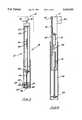
- FIG. 1is a schematic perspective view of a leg for a height adjustable desk
- FIG. 2is a schematic sectioned side elevation of the desk leg of FIG. 1;
- FIG. 3is a schematic top plan view of the desk leg of FIG. 1;
- FIG. 4is a schematic side elevation of a further desk leg
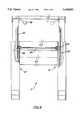
- FIG. 5is a schematic front elevation of a desk frame employing a pair of desk legs, of which one of the legs is the desk leg of FIG. 1;
- FIG. 6is a schematic top plan view of the desk frame of FIG. 5.
- a height adjustable desk frame 11to support a work bench 12 so that the work bench 12 is height adjustable with respect to the supporting floor.
- the frame 11includes legs 10 and 13.
- the legs 10 and 13are not interchangeable.
- the operating mechanism 14is manipulated by the user to adjust the height of the upper portion 15 of the leg 10, with respect to the lower portion 16.
- Motionis transferred to the leg 13 so that the upper portion 17 of the leg 13 is moved relative to the lower portion 18.
- a gas strut 19extends between a plate 20 fixed to the lower portion 18 and an L-shaped bracket 21 fixed to the upper portion 17 to aid in raising the desk and to control lowering of the desk.
- a rack gear 22meshingly engaged with a pinion gear 23, with the pinion gear 23 fixed to the lower portion 18.
- the rack gear 22 and pinion 23aid in motion transfer between the legs 10 and 13.
- An assembly of the bracket 21 and gas strut 19may be removed from within the leg 13 by removal of the threaded fastener 24.
- the bracket 21is particularly shaped so as to be received within the hollow tube 25 of the leg 13.
- the deskcan be made right or left handed in respect of height adjustment operation.
- the mechanism 14includes a shaft 26 which is supported by means of a bush 27 fixed to the upper part 15.
- a bearing or further bush 28is captively located with respect to the shaft 26 but is received within a shaped recess in the upper part 15.
- the shaft 26includes a telescopically associated tube 29 which receives a rod 30.
- the tube 29has a slot 31 through which a pin 32 projects to engage the rod 30.
- the handle 34may be moved outward beyond the edge 46 of the desk to enable operation. This is permitted by means of sliding movement of the pin 32 along the slot 31.
- One extremity of the shaft 26engages a flexible drive 33 extending to and driving a worm gear 48.
- the worm gear 48is rotatably mounted in an L-shaped bracket 35 by means of a bearing 47.
- the bearing 47is captively located with respect to the bracket 35.
- the bracket 35is held in position by means of a threaded fastener 36, with the bracket 35 being adapted to engage within the tube 37 of the upper portion
- the lower end of the worm gear 48is engaged with a nut 38 supported by a pedestal 39 extending to the bottom plate 40.
- the pedestal 39has a threaded pin 41 engaged by a nut 42.
- the pin 41projects through an aperture in the plate 40 while the nut 42 holds the pedestal in position.
- a rack gear 43Fixed to the upper part 15 is a rack gear 43 which is meshingly engaged with a pinion gear 44, fixed with respect to the lower portion 16.
- a shaft 45extends between the pinion gears 23 and 44 in order to transfer motion between the legs 10 and 13.
- the pinion gear 44rotates the shaft 45 which in turn rotates the pinion gear 23 causing the upper portion 17 to move vertically due to the meshing engagement of the pinion gear 23 with the rack gear 22.
- the operating mechanism 14,which incorporates the threaded rod 41, pedestal 39, nut 38, worm gear 48, bracket 35, bearing 47, flexible drive 33, bearing 28 and shaft 26, may be removed as a unit and interchanged with the assembly incorporating the gas strut 19.
- the pin 32is removed which enables withdrawal of the rod 30 by pulling it through the bushing 27. Thereafter, the tube 29 may be raised taking with it the bearing 28.
- the threaded fastener 36is removed as is the nut 42.
- the bracket 35is then raised taking with it the worm gear 48, nut 38 and pedestal 39 together with the bearing 47.
Landscapes
- Tables And Desks Characterized By Structural Shape (AREA)
Abstract
Description
The present invention relates to desk frames and more particularly to adjustable desk frames which have a top surface which is height adjustable.
The present invention relates to improvements in adjustable desk frames such as those disclosed in U.S. Pat. No. 4,850,563.
Desk frames have usually included a top work bench which is supported on two legs which are height adjustable. One of the legs is provided with a handle connected to the operating mechanism which adjusts the height of the legs and therefore the top work bench. The legs are not interchangeable and therefore desks which are left or right handed (in respect of operating mechanism) must be separately manufactured. This greatly increases the cost of manufacture and storage.
It is the object of the present invention to overcome or substantially ameliorate the above disadvantages.
There is disclosed herein a height adjustment mechanism for a height adjustable desk having a pair of spaced legs to support a work bench, each leg including an upper portion to be fixed to the bench, and a lower portion to engage a surface supporting the desk, said mechanism comprising:
a drive shaft having an extremity to be manipulated by a user to case rotation of the shaft about its longitudinal axis;
means to rotatably support said shaft horizontally in said upper portion for rotation about its longitudinal axis;
a worm gear connected to said shaft so that said worm gear will rotate therewith about the longitudinal axis of the worm gear;
means to mount said worm gear in said upper portion so that said worm gear is generally vertically extending and is rotatable about its longitudinal axis; and
a nut to be mounted on said lower portion and threadably engaged with said worm gear so that rotation of said worm gear causes movement of said nut along said worm gear so that in use said rotation causes vertical movement of said upper portion with respect to said lower portion.
There is further disclosed herein a height adjustable desk having a frame, a work bench mounted on the frame, and a height adjustment mechanism to vertically adjust the height of the work bench;
said frame comprising a pair of parallel upwardly extending legs which are horizontally spaced and generally co-extensive, each leg including an upper portion to be fixed to the bench, and a lower portion to engage a surface supporting the desk; and wherein
said height adjustment mechanism includes a drive shaft having an extremity to be manipulated by a user to cause rotation of the shaft about its longitudinal axis, means rotatably supporting said shaft horizontally in the upper portion of one of said legs for rotation about its longitudinal axis, a worm gear connected to said shaft so that said worm gear will rotate therewith about the longitudinal axis of said worm gear, means mounting said worm gear in the upper portion of said one leg so that said worm gear is generally vertically extending and is rotatable about its longitudinal axis, a nut mounted in the lower part of said one leg and threadably engaged with said worm gear so that rotation of said worm gear causes movement of said nut along said worm gear thereby vertically moving said upper portion of said one leg with respect to the lower portion of said one leg, and movement transfer means to cause a corresponding movement of the upper part of the other leg in unison with the upper part of said one leg.
A preferred form of the present invention will now be described by way of example with reference to the accompanying drawings wherein:
FIG. 1 is a schematic perspective view of a leg for a height adjustable desk;
FIG. 2 is a schematic sectioned side elevation of the desk leg of FIG. 1;
FIG. 3 is a schematic top plan view of the desk leg of FIG. 1;
FIG. 4 is a schematic side elevation of a further desk leg;
FIG. 5 is a schematic front elevation of a desk frame employing a pair of desk legs, of which one of the legs is the desk leg of FIG. 1; and
FIG. 6 is a schematic top plan view of the desk frame of FIG. 5.
In the accompanying drawings there is schematically depicted a height adjustable desk frame 11 to support awork bench 12 so that thework bench 12 is height adjustable with respect to the supporting floor. The frame 11 includeslegs legs leg 10, theoperating mechanism 14 is manipulated by the user to adjust the height of theupper portion 15 of theleg 10, with respect to thelower portion 16. Motion is transferred to theleg 13 so that the upper portion 17 of theleg 13 is moved relative to thelower portion 18. In theleg 13, agas strut 19 extends between aplate 20 fixed to thelower portion 18 and an L-shaped bracket 21 fixed to the upper portion 17 to aid in raising the desk and to control lowering of the desk. Fixed to the upper part 17 is arack gear 22 meshingly engaged with apinion gear 23, with thepinion gear 23 fixed to thelower portion 18. Therack gear 22 andpinion 23 aid in motion transfer between thelegs bracket 21 andgas strut 19 may be removed from within theleg 13 by removal of the threadedfastener 24. Thebracket 21 is particularly shaped so as to be received within thehollow tube 25 of theleg 13.
Removably incorporated in theleg 10 is theoperating mechanism 14 so that theoperating mechanism 14 may be removed as an entire assembly and interchanged with the assembly incorporating thegas strut 19. By this arrangement, the desk can be made right or left handed in respect of height adjustment operation.
Themechanism 14 includes ashaft 26 which is supported by means of abush 27 fixed to theupper part 15. A bearing orfurther bush 28 is captively located with respect to theshaft 26 but is received within a shaped recess in theupper part 15. Theshaft 26 includes a telescopically associatedtube 29 which receives arod 30. Thetube 29 has aslot 31 through which apin 32 projects to engage therod 30. In operation, thehandle 34 may be moved outward beyond theedge 46 of the desk to enable operation. This is permitted by means of sliding movement of thepin 32 along theslot 31. One extremity of theshaft 26 engages aflexible drive 33 extending to and driving aworm gear 48. Theworm gear 48 is rotatably mounted in an L-shaped bracket 35 by means of abearing 47. Thebearing 47 is captively located with respect to thebracket 35. Thebracket 35 is held in position by means of a threadedfastener 36, with thebracket 35 being adapted to engage within thetube 37 of theupper portion 15.
The lower end of theworm gear 48 is engaged with anut 38 supported by apedestal 39 extending to thebottom plate 40. Thepedestal 39 has a threadedpin 41 engaged by anut 42. Thepin 41 projects through an aperture in theplate 40 while thenut 42 holds the pedestal in position.
By rotation of theworm gear 48 about its longitudinal axis, engagement with thenut 38 will raise and lower theupper portion 15 with respect to thelower portion 16. This is accomplished merely by rotation of thehandle 34 about the longitudinal axis of theshaft 26.
Fixed to theupper part 15 is arack gear 43 which is meshingly engaged with apinion gear 44, fixed with respect to thelower portion 16. Ashaft 45 extends between thepinion gears legs upper portion 15 is caused to move vertically, it takes with it therack gear 43 causing rotation of thepinion gear 44. Thepinion gear 44 rotates theshaft 45 which in turn rotates thepinion gear 23 causing the upper portion 17 to move vertically due to the meshing engagement of thepinion gear 23 with therack gear 22.
Theoperating mechanism 14, which incorporates the threadedrod 41,pedestal 39,nut 38,worm gear 48,bracket 35, bearing 47,flexible drive 33, bearing 28 andshaft 26, may be removed as a unit and interchanged with the assembly incorporating thegas strut 19.
To remove theoperating mechanism 14, thepin 32 is removed which enables withdrawal of therod 30 by pulling it through thebushing 27. Thereafter, thetube 29 may be raised taking with it the bearing 28. The threadedfastener 36 is removed as is thenut 42. Thebracket 35 is then raised taking with it theworm gear 48,nut 38 andpedestal 39 together with thebearing 47.
Claims (15)
1. A height adjustment mechanism for a height adjustable desk having a pair of spaced legs to support a work bench, each leg including an upper portion to be fixed to the bench, and a lower portion to engage a surface supporting the desk, said mechanism comprising:
a drive shaft having an extremity to be manipulated by a user to cause rotation of the shaft about its longitudinal axis;
means to rotatably support said shaft generally horizontally in said upper portion for rotation about its longitudinal axis;
a worm gear connected to said shaft so that said worm gear will rotate therewith about the longitudinal axis of the worm gear;
means to mount said worm gear in said upper portion so that said worm gear is generally vertically extending and is rotatable about its longitudinal axis;
a nut to be mounted on said lower portion and threadably engaged with said worm gear so that rotation of said worm gear causes movement of said nut along said worm gear so that in use said rotation causes vertical movement of said upper portion with respect to said lower portion;
a pedestal having said nut fixed to an upper end thereof, with said pedestal having a lower end to engage a respective one of the lower portions; and
a mounting bracket rotatable supporting an upper end of said worm gear, said bracket being fixed to a respective one of the upper portions.
2. The mechanism of claim 1, wherein said worm gear is connected to said shaft by a flexible drive.
3. The mechanism of claim 2, wherein said nut is mounted on a pedestal, so that upon installation in said lower part, said nut is spaced from said surface.
4. The mechanism of claim 3, further including a mounting bracket to be fixed to said upper part, and a bearing rotatably supporting said worm gear in said bracket.
5. The mechanism of claim 1, wherein said nut is mounted on a pedestal, so that upon installation in said lower part, said nut is spaced from said surface.
6. The mechanism of claim 5, further including a mounting bracket to be fixed to said upper part, and a bearing rotatably supporting said worm gear in said bracket.
7. A height adjustable desk having a frame, a work bench mounted on the frame, and a height adjustment mechanism to vertically adjust the height of the work bench;
said frame comprising a pair of parallel upwardly extending legs which are horizontally spaced and generally co-extensive, each leg including an upper portion to be fixed to the bench, and a lower portion to engage a surface supporting the desk; and wherein
said height adjustment mechanism includes a drive shaft having an extremity to be manipulated by a user to cause rotation of the shaft about its longitudinal axis, means rotatably supporting said shaft generally horizontally in the upper portion of one of said legs for rotation about its longitudinal axis, a worm gear connected to said shaft so that said worm gear will rotate therewith about the longitudinal axis of said worm gear, means mounting said worm gear in the upper portion of said one leg so that said worm gear is generally vertically extending and is rotatable about its longitudinal axis, a nut mounted in the lower part of said one leg and threadably engaged with said worm gear so that rotation of said worm gear causes movement of said nut along said worm gear thereby vertically moving said upper portion of said one leg with respect to the lower portion of said one leg, a pedestal having said nut fixed to an upper end thereof, with said pedestal having a lower end fixed to said lower portion of said one leg, a mounting bracket notably supporting an upper end of said worm gear, said bracket being fixed to the upper portion of said one leg, and movement transfer means to cause a corresponding movement of the upper part of the other leg in unison with the upper part of said one leg.
8. The desk of claim 7, wherein said movement transfer means includes a first rack fixed to the upper part of said one leg, a first gear meshingly engaged with said first rack, said first gear being mounted on the lower part of said first leg, a second rack, said second rack being fixed to the upper part of said second leg, a second gear, said second gear being mounted on the lower part of said second leg and meshingly engaged with said second rack, a shaft fixed to said first gear and said second gear so that they rotate in unison to thereby cause movement of the upper part of said second leg in unison with the upper part of said first leg.
9. The desk of claim 7, wherein each upper part has a portion which is telescopically received within a portion of the associated lower part.
10. The desk of claim 7, further including a transverse brace extending between the two legs, and wherein the shaft extending between said first and second gears is located adjacent said transverse brace.
11. The mechanism of claim 7, wherein said worm gear is connected to said shaft by a flexible drive.
12. The mechanism of claim 11, wherein said nut is mounted on a pedestal, so that upon installation in said lower part, said nut is spaced from said surface.
13. The mechanism of claim 12, further including a mounting bracket to be fixed to said upper part, and a bearing rotatably supporting said worm gear in said bracket.
14. The mechanism of claim 7, wherein said nut is mounted on a pedestal, so that upon installation in said lower part, said nut is spaced from said surface.
15. The mechanism of claim 14, further including a mounting bracket to be fixed to said upper part, and a bearing rotatably supporting said worm gear in said bracket.
Applications Claiming Priority (2)
| Application Number | Priority Date | Filing Date | Title |
|---|---|---|---|
| AUPM3230 | 1994-01-04 | ||
| AUPM3230AAUPM323094A0 (en) | 1994-01-04 | 1994-01-04 | A desk frame |
Publications (1)
| Publication Number | Publication Date |
|---|---|
| US5549053Atrue US5549053A (en) | 1996-08-27 |
Family
ID=3777854
Family Applications (1)
| Application Number | Title | Priority Date | Filing Date |
|---|---|---|---|
| US08/367,591Expired - Fee RelatedUS5549053A (en) | 1994-01-04 | 1995-01-03 | Desk frame |
Country Status (2)
| Country | Link |
|---|---|
| US (1) | US5549053A (en) |
| AU (1) | AUPM323094A0 (en) |
Cited By (26)
| Publication number | Priority date | Publication date | Assignee | Title |
|---|---|---|---|---|
| WO1997038239A1 (en)* | 1996-04-09 | 1997-10-16 | Kinnarps Ab | Table construction |
| US5706739A (en)* | 1996-12-12 | 1998-01-13 | Ergotech (1993) Inc. | Height adjustable counterbalance workstation |
| US5758586A (en)* | 1997-01-09 | 1998-06-02 | Kieser; Joyce R. | Adjustable height table |
| US6024025A (en)* | 1999-02-05 | 2000-02-15 | Equipto | Table lift mechanism |
| US6062148A (en)* | 1997-08-01 | 2000-05-16 | Steelcase Development Inc. | Height adjustable support for computer equipment and the like |
| US6263809B1 (en)* | 1999-03-04 | 2001-07-24 | Argo Office B.V. | Height-adjustable support for supporting a table top |
| US6286441B1 (en)* | 1999-04-30 | 2001-09-11 | Steelcase Development Corporation | Height adjustable work surface and control therefor |
| US6312069B1 (en)* | 2000-07-17 | 2001-11-06 | Teng-Tsai Weng | Height adjustable structure of desk combination |
| US6345854B1 (en) | 1998-12-23 | 2002-02-12 | Vt Holdings Ii, Inc. | Mechanism for synchronizing and controlling multiple actuators of a slide out room of mobile living quarters |
| DE10112940A1 (en)* | 2001-03-17 | 2002-10-02 | Fleischer Bueromoebelwerk Gmbh | Table for a computer monitor or a CAD workstation, the height of which can be rapidly adjusted to a chosen working height that is suitable for use by either a standing or sitting person |
| US6565137B1 (en)* | 2000-09-13 | 2003-05-20 | Johnson Controls Technology Company | Table top lift assembly for center stack |
| WO2004004621A3 (en)* | 2002-07-05 | 2004-04-22 | Luigi Anzelini | Table for disabled person |
| KR20040063186A (en)* | 2003-01-06 | 2004-07-14 | 손경섭 | A desk for teaching |
| US20050248239A1 (en)* | 2004-05-04 | 2005-11-10 | Hekman Furniture Company | Adjustable height casegood and desk |
| US20050247239A1 (en)* | 2004-05-04 | 2005-11-10 | Newhouse Thomas J | Adjustable height casegood and desk |
| USD512850S1 (en) | 2004-06-02 | 2005-12-20 | Hekman Furniture Company | Work station |
| USD528822S1 (en) | 2004-12-17 | 2006-09-26 | Hekman Furniture Company | Adjustable height work station |
| USD538068S1 (en) | 2005-07-06 | 2007-03-13 | Hekman Furniture Company | Height adjustable work station |
| US7744142B2 (en) | 2003-07-31 | 2010-06-29 | Lippert Components, Inc. | Strap bed lift |
| US20100175592A1 (en)* | 2007-09-13 | 2010-07-15 | Hans Looser | Piece of furniture |
| US20110023758A1 (en)* | 2006-02-10 | 2011-02-03 | Michael Overgaard | Telescopic lifting column for height adjustment of elevatable tables |
| US20130167757A1 (en)* | 2011-12-28 | 2013-07-04 | Chi-Cheng Tsai | Adjustable desk |
| US9656590B2 (en) | 2014-05-15 | 2017-05-23 | Lippert Components, Inc. | Bed lift mounting member |
| US10918202B1 (en)* | 2019-10-25 | 2021-02-16 | Fong-Lung Sie | Lifting table |
| US11957242B2 (en)* | 2019-03-20 | 2024-04-16 | Dirtt Environmental Solutions Ltd. | Height adjusting and leveling worksurface cantilever |
| US20250213032A1 (en)* | 2022-08-12 | 2025-07-03 | Qidong Vision Mounts Manufacturing Co.,Ltd. | Electric height-adjustable desk |
Citations (11)
| Publication number | Priority date | Publication date | Assignee | Title |
|---|---|---|---|---|
| US668627A (en)* | 1900-08-13 | 1901-02-26 | Charles S Crow | Portable and adjustable scaffold. |
| US906538A (en)* | 1908-02-12 | 1908-12-15 | Alfred Limoges | Exerciser. |
| US2368748A (en)* | 1943-02-19 | 1945-02-06 | Hard Mfg Company | Over-bed table |
| US3908565A (en)* | 1973-12-26 | 1975-09-30 | John W Burnett | Transportable overbed table |
| US4590856A (en)* | 1983-11-26 | 1986-05-27 | M.A.N.-Roland Druckmaschinen Aktiengesellschaft | Lifter-type inker for rotary printing machine including rotational shock dampening means |
| US4604955A (en)* | 1981-10-03 | 1986-08-12 | Willy Fleischer Metallwarenfabrik Gmbh & Co. | Height-adjustable table for work places with video screen |
| US4615279A (en)* | 1984-12-21 | 1986-10-07 | Haye Cornelis Franciscus De | Vertically adjustable table |
| US4850563A (en)* | 1987-06-06 | 1989-07-25 | Ergonomic Equipment Pty. Ltd. | Adjustable desk frame |
| US4981085A (en)* | 1989-08-07 | 1991-01-01 | Weber-Knapp Company | Table lift mechanism |
| US5337678A (en)* | 1993-01-07 | 1994-08-16 | Ergonomic Equipment Pty. Ltd. | Adjustable desk frame |
| US5367963A (en)* | 1991-10-01 | 1994-11-29 | Embru-Werke, Mantel & Cie. | Office table |
- 1994
- 1994-01-04AUAUPM3230Apatent/AUPM323094A0/ennot_activeAbandoned
- 1995
- 1995-01-03USUS08/367,591patent/US5549053A/ennot_activeExpired - Fee Related
Patent Citations (11)
| Publication number | Priority date | Publication date | Assignee | Title |
|---|---|---|---|---|
| US668627A (en)* | 1900-08-13 | 1901-02-26 | Charles S Crow | Portable and adjustable scaffold. |
| US906538A (en)* | 1908-02-12 | 1908-12-15 | Alfred Limoges | Exerciser. |
| US2368748A (en)* | 1943-02-19 | 1945-02-06 | Hard Mfg Company | Over-bed table |
| US3908565A (en)* | 1973-12-26 | 1975-09-30 | John W Burnett | Transportable overbed table |
| US4604955A (en)* | 1981-10-03 | 1986-08-12 | Willy Fleischer Metallwarenfabrik Gmbh & Co. | Height-adjustable table for work places with video screen |
| US4590856A (en)* | 1983-11-26 | 1986-05-27 | M.A.N.-Roland Druckmaschinen Aktiengesellschaft | Lifter-type inker for rotary printing machine including rotational shock dampening means |
| US4615279A (en)* | 1984-12-21 | 1986-10-07 | Haye Cornelis Franciscus De | Vertically adjustable table |
| US4850563A (en)* | 1987-06-06 | 1989-07-25 | Ergonomic Equipment Pty. Ltd. | Adjustable desk frame |
| US4981085A (en)* | 1989-08-07 | 1991-01-01 | Weber-Knapp Company | Table lift mechanism |
| US5367963A (en)* | 1991-10-01 | 1994-11-29 | Embru-Werke, Mantel & Cie. | Office table |
| US5337678A (en)* | 1993-01-07 | 1994-08-16 | Ergonomic Equipment Pty. Ltd. | Adjustable desk frame |
Cited By (33)
| Publication number | Priority date | Publication date | Assignee | Title |
|---|---|---|---|---|
| WO1997038239A1 (en)* | 1996-04-09 | 1997-10-16 | Kinnarps Ab | Table construction |
| US5706739A (en)* | 1996-12-12 | 1998-01-13 | Ergotech (1993) Inc. | Height adjustable counterbalance workstation |
| US5758586A (en)* | 1997-01-09 | 1998-06-02 | Kieser; Joyce R. | Adjustable height table |
| US6062148A (en)* | 1997-08-01 | 2000-05-16 | Steelcase Development Inc. | Height adjustable support for computer equipment and the like |
| US6345854B1 (en) | 1998-12-23 | 2002-02-12 | Vt Holdings Ii, Inc. | Mechanism for synchronizing and controlling multiple actuators of a slide out room of mobile living quarters |
| US6024025A (en)* | 1999-02-05 | 2000-02-15 | Equipto | Table lift mechanism |
| US6263809B1 (en)* | 1999-03-04 | 2001-07-24 | Argo Office B.V. | Height-adjustable support for supporting a table top |
| US6286441B1 (en)* | 1999-04-30 | 2001-09-11 | Steelcase Development Corporation | Height adjustable work surface and control therefor |
| US6312069B1 (en)* | 2000-07-17 | 2001-11-06 | Teng-Tsai Weng | Height adjustable structure of desk combination |
| US6565137B1 (en)* | 2000-09-13 | 2003-05-20 | Johnson Controls Technology Company | Table top lift assembly for center stack |
| DE10112940A1 (en)* | 2001-03-17 | 2002-10-02 | Fleischer Bueromoebelwerk Gmbh | Table for a computer monitor or a CAD workstation, the height of which can be rapidly adjusted to a chosen working height that is suitable for use by either a standing or sitting person |
| WO2004004621A3 (en)* | 2002-07-05 | 2004-04-22 | Luigi Anzelini | Table for disabled person |
| KR20040063186A (en)* | 2003-01-06 | 2004-07-14 | 손경섭 | A desk for teaching |
| US7744142B2 (en) | 2003-07-31 | 2010-06-29 | Lippert Components, Inc. | Strap bed lift |
| US8038193B2 (en) | 2003-07-31 | 2011-10-18 | Lippert Components, Inc. | Strap bed lift |
| US20050248239A1 (en)* | 2004-05-04 | 2005-11-10 | Hekman Furniture Company | Adjustable height casegood and desk |
| US20050247239A1 (en)* | 2004-05-04 | 2005-11-10 | Newhouse Thomas J | Adjustable height casegood and desk |
| USD524076S1 (en) | 2004-06-02 | 2006-07-04 | Hekman Furniture Company | Work station |
| USD527202S1 (en) | 2004-06-02 | 2006-08-29 | Hackman Furniture Company | Work station |
| USD524570S1 (en) | 2004-06-02 | 2006-07-11 | Hekman Furniture Company | Work station |
| USD512850S1 (en) | 2004-06-02 | 2005-12-20 | Hekman Furniture Company | Work station |
| USD528822S1 (en) | 2004-12-17 | 2006-09-26 | Hekman Furniture Company | Adjustable height work station |
| USD538068S1 (en) | 2005-07-06 | 2007-03-13 | Hekman Furniture Company | Height adjustable work station |
| US8001909B2 (en)* | 2006-02-10 | 2011-08-23 | Michael Overgaard | Telescopic lifting column for height adjustment of elevatable tables |
| US20110023758A1 (en)* | 2006-02-10 | 2011-02-03 | Michael Overgaard | Telescopic lifting column for height adjustment of elevatable tables |
| US20100175592A1 (en)* | 2007-09-13 | 2010-07-15 | Hans Looser | Piece of furniture |
| US8256358B2 (en)* | 2007-09-13 | 2012-09-04 | Moll Funktionsboebel GmbH | Piece of furniture |
| US20130167757A1 (en)* | 2011-12-28 | 2013-07-04 | Chi-Cheng Tsai | Adjustable desk |
| US8661989B2 (en)* | 2011-12-28 | 2014-03-04 | Sing-Bee Enterprise Co., Ltd. | Adjustable desk |
| US9656590B2 (en) | 2014-05-15 | 2017-05-23 | Lippert Components, Inc. | Bed lift mounting member |
| US11957242B2 (en)* | 2019-03-20 | 2024-04-16 | Dirtt Environmental Solutions Ltd. | Height adjusting and leveling worksurface cantilever |
| US10918202B1 (en)* | 2019-10-25 | 2021-02-16 | Fong-Lung Sie | Lifting table |
| US20250213032A1 (en)* | 2022-08-12 | 2025-07-03 | Qidong Vision Mounts Manufacturing Co.,Ltd. | Electric height-adjustable desk |
Also Published As
| Publication number | Publication date |
|---|---|
| AUPM323094A0 (en) | 1994-01-27 |
Similar Documents
| Publication | Publication Date | Title |
|---|---|---|
| US5549053A (en) | Desk frame | |
| US5337678A (en) | Adjustable desk frame | |
| US4850563A (en) | Adjustable desk frame | |
| US5996961A (en) | Height-adjustable workstand support | |
| US20090134303A1 (en) | Automatically varying equipment support | |
| CN111336358A (en) | Remove regulation formula hospital financial affairs statistics device | |
| US2888732A (en) | Adjustable beds for burial caskets | |
| CN118455735A (en) | Intelligent laser welding device for aircraft wall plate | |
| CN110898873A (en) | Multifunctional demonstration device for physical teaching | |
| CN214213692U (en) | A simple lifting workbench | |
| CN212134031U (en) | LED display screen single-point detection device | |
| CN222764945U (en) | Multifunctional table and chair combination | |
| CN215583423U (en) | Adjustable computer desk for students | |
| CN112053611A (en) | Case display device for financial teaching | |
| CN208614733U (en) | Rack is used in a kind of machining | |
| US2857225A (en) | Vertically adjustable top for furniture | |
| CN220651582U (en) | Propaganda show shelf | |
| CN217167063U (en) | Angle-adjustable welding tool | |
| CN114747873B (en) | Working platform with cartoon effect and use method | |
| CN220237237U (en) | Nursing operation panel for clinical trial | |
| CN222888724U (en) | Table frame | |
| CN222476636U (en) | Adjustable bedplate frame | |
| CN220631468U (en) | Adjustable student chair | |
| CN211793163U (en) | A cultivation frame for chrysanthemum is planted | |
| CN220124386U (en) | Iron art product installation mount |
Legal Events
| Date | Code | Title | Description |
|---|---|---|---|
| AS | Assignment | Owner name:ERGONOMIX ARMDEC PTY. LTD., AUSTRALIA Free format text:ASSIGNMENT OF ASSIGNORS INTEREST;ASSIGNOR:GROUT, JOHN EDWIN;REEL/FRAME:007423/0167 Effective date:19950222 | |
| REMI | Maintenance fee reminder mailed | ||
| FPAY | Fee payment | Year of fee payment:4 | |
| SULP | Surcharge for late payment | ||
| AS | Assignment | Owner name:ERGONOMIX PLUS PTY LTD, AUSTRALIA Free format text:ASSIGNMENT OF ASSIGNORS INTEREST;ASSIGNOR:ERGONOMIX ARMDEC PTY LIMITED;REEL/FRAME:011620/0453 Effective date:20010213 | |
| AS | Assignment | Owner name:ERGONOMIX PLUS PTY LTD, AUSTRALIA Free format text:CORRECTIVE ASSIGNMENT TO CORRECT THE ASSIGNEE'S ADDRESS, PREVIOUSLY RECORDED ON REEL 011620 FRAME 0453;ASSIGNOR:ERGONOMIX ARMDEC PTY LIMITED;REEL/FRAME:012653/0124 Effective date:20010213 | |
| REMI | Maintenance fee reminder mailed | ||
| LAPS | Lapse for failure to pay maintenance fees | ||
| FP | Lapsed due to failure to pay maintenance fee | Effective date:20040827 | |
| STCH | Information on status: patent discontinuation | Free format text:PATENT EXPIRED DUE TO NONPAYMENT OF MAINTENANCE FEES UNDER 37 CFR 1.362 |