US5548605A - Monolithic microchannel heatsink - Google Patents
Monolithic microchannel heatsinkDownload PDFInfo
- Publication number
- US5548605A US5548605AUS08/440,595US44059595AUS5548605AUS 5548605 AUS5548605 AUS 5548605AUS 44059595 AUS44059595 AUS 44059595AUS 5548605 AUS5548605 AUS 5548605A
- Authority
- US
- United States
- Prior art keywords
- laser diode
- heatsink
- microchannels
- monolithic
- diode
- Prior art date
- Legal status (The legal status is an assumption and is not a legal conclusion. Google has not performed a legal analysis and makes no representation as to the accuracy of the status listed.)
- Expired - Lifetime
Links
- XUIMIQQOPSSXEZ-UHFFFAOYSA-NSiliconChemical compound[Si]XUIMIQQOPSSXEZ-UHFFFAOYSA-N0.000claimsabstractdescription35
- 229910052710siliconInorganic materials0.000claimsabstractdescription35
- 239000010703siliconSubstances0.000claimsabstractdescription35
- 238000004519manufacturing processMethods0.000claimsabstractdescription9
- 239000000758substrateSubstances0.000claimsdescription20
- XLYOFNOQVPJJNP-UHFFFAOYSA-NwaterSubstancesOXLYOFNOQVPJJNP-UHFFFAOYSA-N0.000claimsdescription14
- 239000011521glassSubstances0.000claimsdescription6
- 238000001816coolingMethods0.000abstractdescription29
- 238000003491arrayMethods0.000abstractdescription11
- 230000035515penetrationEffects0.000abstractdescription4
- 230000003287optical effectEffects0.000abstractdescription2
- 235000012431wafersNutrition0.000description13
- 230000004907fluxEffects0.000description6
- 230000008901benefitEffects0.000description5
- 238000005530etchingMethods0.000description5
- KWYUFKZDYYNOTN-UHFFFAOYSA-MPotassium hydroxideChemical compound[OH-].[K+]KWYUFKZDYYNOTN-UHFFFAOYSA-M0.000description3
- 230000007423decreaseEffects0.000description3
- 230000007547defectEffects0.000description2
- 238000000034methodMethods0.000description2
- 230000008569processEffects0.000description2
- 239000007787solidSubstances0.000description2
- RYGMFSIKBFXOCR-UHFFFAOYSA-NCopperChemical compound[Cu]RYGMFSIKBFXOCR-UHFFFAOYSA-N0.000description1
- 229910001218Gallium arsenideInorganic materials0.000description1
- 230000009471actionEffects0.000description1
- 239000012080ambient airSubstances0.000description1
- 239000004020conductorSubstances0.000description1
- 229910052802copperInorganic materials0.000description1
- 239000010949copperSubstances0.000description1
- 239000013078crystalSubstances0.000description1
- 230000006378damageEffects0.000description1
- 230000003247decreasing effectEffects0.000description1
- 230000000694effectsEffects0.000description1
- 238000005516engineering processMethods0.000description1
- 230000017525heat dissipationEffects0.000description1
- 239000000463materialSubstances0.000description1
- 230000007246mechanismEffects0.000description1
- 230000004048modificationEffects0.000description1
- 238000012986modificationMethods0.000description1
- 238000004806packaging method and processMethods0.000description1
- 238000005086pumpingMethods0.000description1
- 230000005855radiationEffects0.000description1
- 230000006798recombinationEffects0.000description1
- 238000005215recombinationMethods0.000description1
- 230000004044responseEffects0.000description1
- 239000004065semiconductorSubstances0.000description1
- 238000004904shorteningMethods0.000description1
- 239000000126substanceSubstances0.000description1
Images


Classifications
- H—ELECTRICITY
- H01—ELECTRIC ELEMENTS
- H01S—DEVICES USING THE PROCESS OF LIGHT AMPLIFICATION BY STIMULATED EMISSION OF RADIATION [LASER] TO AMPLIFY OR GENERATE LIGHT; DEVICES USING STIMULATED EMISSION OF ELECTROMAGNETIC RADIATION IN WAVE RANGES OTHER THAN OPTICAL
- H01S5/00—Semiconductor lasers
- H01S5/02—Structural details or components not essential to laser action
- H01S5/024—Arrangements for thermal management
- H01S5/02407—Active cooling, e.g. the laser temperature is controlled by a thermo-electric cooler or water cooling
- H01S5/02423—Liquid cooling, e.g. a liquid cools a mount of the laser
- H—ELECTRICITY
- H01—ELECTRIC ELEMENTS
- H01S—DEVICES USING THE PROCESS OF LIGHT AMPLIFICATION BY STIMULATED EMISSION OF RADIATION [LASER] TO AMPLIFY OR GENERATE LIGHT; DEVICES USING STIMULATED EMISSION OF ELECTROMAGNETIC RADIATION IN WAVE RANGES OTHER THAN OPTICAL
- H01S5/00—Semiconductor lasers
- H01S5/40—Arrangement of two or more semiconductor lasers, not provided for in groups H01S5/02 - H01S5/30
- H01S5/4025—Array arrangements, e.g. constituted by discrete laser diodes or laser bar
Definitions
- the present inventionrelates to microchannel cooling of laser diodes and more specifically, it relates to a monolithic microchannel heatsink for cooling laser diode arrays.
- Laser diodeshave many advantages over conventional lasers. Laser diodes are small and compact, they are efficient at converting electrical energy into laser energy, and they are reliable. However, when a laser diode is operated at a high average power, it generates a substantial amount of heat in a small volume, thereby raising the temperature of the diode which causes negative effects such as a wavelength shift and a loss of efficiency. If the temperature gets high enough, destruction of the diode package may result. Therefore, present uses of laser diodes are generally limited to applications requiring low average power.
- the laser diodeWhen compared with other lasers, the laser diode is distinguishable by several features.
- One distinguishing featureis the size of the laser diode.
- Laser diodescan be manufactured in a package much smaller than other laser devices such as gas lasers that require large gas tubes and specialized optics equipment such as Brewster's windows, mirrors, spatial filters, and lenses.
- Another distinguishing feature of the laser diodeis its efficiency at converting the input electrical power to output laser intensity. Laser diodes can readily achieve efficiencies of 50% or more in converting electrical energy to laser energy, while other lasers have efficiencies from 10% to less than 1%. For example, the highest efficiency achieved by other lasers is attained by the CO 2 laser, which may attain an efficiency of 10%.
- laser diodeshave not been applied in high power applications due primarily to the problem of heat dissipation.
- Other laserssuch as the copper vapor lasers currently in use for high power applications, have an efficiency of 1% or less. Additional distinguishing features of the laser diode include a fast response to control signals, and simplicity of design. Manufacturing of laser diodes is known in the art, and a capability exists to manufacture many types of laser diodes.
- an edge emitting laser diodeis the edge emitting laser diodes, often termed "laser diode bars". These diodes emit laser light along a length of their edge. For example, an edge emitting laser diode can output a beam that has an emitting edge length of one centimeter, and a width of 0.3 mm.
- an edge emitting laser diodewill be manufactured of a single block of GaAs, with a pn junction formed in a plane throughout the block, and the facets positioned on opposing edges of the plane defined by the pn junction. Conductors are constructed on each side of the pn junction so that when current is applied, current passes through the pn junction. The current creates a population inversion across the pn junction, and lasing action can occur.
- the basic mechanisms leading to heat production in a diodeare the series resistances of the diode and non-radiative recombination.
- the series resistancesinclude the resistance of the semiconductor material, and the resistance of the contacts, which produce heat during current flow. The resistances produce heat as current is applied, in an amount of heat flux proportional to I 2 R.
- a diodeDue to this heat production, a basic limitation on the output intensity of a diode is temperature buildup from heat produced in the pumping process. For maximum efficiency, a diode must have a temperature that is below 25° C. For reliable, long lived operation of the diode, temperatures may be less than 50° C. without substantial loss of efficiency. Temperatures even moderately above 50° C. will substantially affect efficiency and reliability, substantially shortening the useful life of the diode. Furthermore, at higher temperatures the output light will be shifted in wavelength. High temperatures encourage the growth of defects in the laser diode, which decrease efficiency. A larger current may be applied to compensate for the decreased efficiency, which then produces even more heat, encouraging the growth of even more defects and a greater loss of efficiency. If a diode could be maintained at or near its optimum temperature, then the diode will have its maximum efficiency and lifetime, and emit a constant wavelength.
- diodesare often operated in a pulsed mode wherein current is applied to the diode during only a portion of the operating time. In this mode, the heat has an opportunity to dissipate during the time when current is off.
- a figure that describes the percentage of time that the diode is pulsedis the "duty cycle". For example, a duty cycle of 1% corresponds to a diode that is actuated with current only once in 100 cycles.
- laser diodeswill be operated at a duty cycle of 1% and a supplied current of fifty to a hundred amps/cm of length. However, if some extra cooling is available, higher duty cycles can be attained. If much more substantial cooling were available, continuous (cw) operation may be obtainable for optimum current levels.
- the cooling problemis of particular significance for arrays of laser diodes.
- a feature of laser diode arraysis the high intensity output provided from the closely packed laser diodes.
- Another advantage of diode arraysis that the output beam's area can be made larger simply by increasing the area of the array. To obtain the higher intensity, the laser diodes in the array should be positioned closer together. However, as a result of close positioning, the heat flux from each laser bar will add with the heat flux of the adjoining laser bar, and without aggressive cooling the temperature may increase rapidly. At a high output power (a high intensity and long duty cycle), the amount of heat flux produced in each diode becomes very substantial.
- the average output intensity of a diode arrayis substantially limited by its ability to sink heat.
- average power outputmust be limited by maintaining the current and duty cycle at a level sufficient to prevent damaging temperature buildup.
- the heat flux in a diode arrayis substantial during a period of high output. Without additional cooling, a laser diode array operated at a high average power will produce a large heat flux which can cause a rapid temperature increase, leading to device failure and other temperature associated problems discussed above. Therefore, a higher intensity output will generally require a more effective cooling system.
- a laser diodecould be cooled sufficiently to produce a high average power.
- Such a laser diode arraywould have many uses including application as an efficient pump source for pulsed solid state lasers.
- a silicon waferhas slots sawn in it that allow diode laser bars to be mounted (soldered) in contact with the silicon.
- Microchannelsare etched into the back of the wafer to provide cooling of the diode bars.
- the channelsare rotated from an angle perpendicular to the dioderelative which allows increased penetration between the mounted diode bars.
- This inventionenables the fabrication of monolithic silicon microchannel heatsinks for laser diodes.
- the heatsinkshave low thermal resistance because of the close proximity of the microchannels to the laser diode being cooled. This allows high average power operation of two-dimensional laser diode arrays that have a high density of laser diode bars and therefore high optical power density.
- Monolithic silicon microchannel heatsinkshave applications in cooling of high power diode laser arrays for use as a pump source for high power solid state lasers or any application where high power laser diode arrays are used. These heatsinks can also be used to cool other devices that generate high thermal loads.
- FIG. 1Ashows the opening in a silicon mask aligned to the (111) plane.
- FIG. 1Bshows a sectional side view of the silicon mask of FIG. 1A where the etched feature is partially completed.
- FIG. 1Cshows a sectional side view of the silicon mask of FIG. 1A where the etched feature is etched to completion.
- FIG. 2Ashows etched cooling channels running end to end and the resulting diode bar spacing.
- FIG. 2Bshows the back plane view of the cooling channels of FIG. 2A.
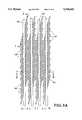
- FIG. 3Ashows a back plane view of etched cooling channels that have been rotated.
- FIG. 3Bshows a side view of section A--A of FIG. 3A.
- FIG. 3Cshows a side view of section B--B of FIG. 3A.
- FIG. 4shows an end view of one embodiment of the heatsink.
- Laser diodes barsneed to be mounted in an orientation that allows light to be emitted from the laser apertures and they need to be aggressively cooled to operate at high duty factor. Costs of fabrication are reduced when large numbers of laser diode bars are mounted on a single microchannel heatsink (back plane monolithic heatsink). In order to achieve aggressive cooling, the thermal impedance of the overall package needs to be extremely low. To obtain the level of thermal performance needed in a silicon microchannel heatsink package for high duty factor laser diodes, the laser diodes have to be in very close proximity to the microchannels. In order to meet these criteria it is necessary to mount the laser diode bars (arrays) within the silicon. This is accomplished by sawing or etching into the surface of the silicon wafer to create mounting surfaces for the laser diode bars that are oriented so the laser radiation can be emitted. These mounting surfaces can be rectangular shaped.
- Anisotropic etchinghas been used to etch microchannels in silicon wafers for several years.
- the microchannel heatsinks that have been developed using this technologycan have a very low thermal impedance and have been used to cool devices that generate extremely high thermal loads such as VLSI chips and laser diodes.
- Anisotropic etching of silicontakes advantage of the fact that some chemicals (most commonly potassium hydroxide) etch crystal planes of different orientation at different rates.
- the ratio of the etch rates for the (110) to the (111) planescan be as high as 600:1 but in practice is closer to 200:1.
- the difference in etch ratescan be exploited to etch channels that are perpendicular to the surface of the wafer. This is accomplished by creating a mask on the surface of the wafer that is aligned with the (111) planes in the wafer. When etched, these slow etching, perpendicular (111) planes then become the walls of the channels. Because these masks can be made photolithographically, the feature sizes created by this process can be very small and their resolution and accuracy tightly controlled.
- FIG. 1Ashows the opening 2 in the mask 4 aligned to the (111) plane of silicon substrate 6 shown in FIG. 1B.
- a sectional view of the etched feature 8 partially completedis shown in FIG. 1B.
- Etched feature 8is shown to completion in FIG. 1C.
- FIG. 2Ashows a side view of a prior art etched silicon microchannel heatsink with the channels 10 running end to end and the resulting spacing of diode bars 12.
- water 14flows into silicon heatsink 16 through glass manifold 18 at entrance portion 20.
- Water 14flows through channels 10 of heatsink 16 and out through glass manifold 18 at exit portion 22, thus carrying heat from diode bars 12.
- FIG. 2Bshows the back plane view of the prior art cooling channels of FIG. 2A. Water 14 flows into heatsink 16 at entrance portion 20 and out at exit portion 22.
- a monolithic microchannel heatsinkcomprises a silicon substrate; a plurality of parallel laser diode bar slots formed in a first side of the substrate; a plurality of parallel microchannels formed in a second side of the substrate; and a glass water manifold formed in the second side of the substrate.
- the plurality of parallel microchannelsare oriented at an angle ⁇ with respect to the plurality of parallel laser diode bar slots, where 90°> ⁇ >0°.
- the plurality of microchannelsare thus angularly rotated with respect to the plurality of laser diode bar slots.
- the microchannelsare greater than 0° and less than 90° with respect to the plurality of laser diode bars and laser diode bar slots.
- Each laser diode baris fixedly and thermally connected to the silicon substrate within a separate laser diode bar slot.
- the monolithic microchannel heatsinkcan be made by creating a mask on the surface of a ⁇ 100>oriented silicon wafer; aligning the mask with the (111) plane of the wafer; and applying an etchant through the mask to the silicon wafer.
- FIG. 3Ashows a back plane view of an embodiment where the etched cooling channels 30 have been rotated.
- FIG. 3Bshows a side view of section A--A of FIG. 3A, where water 32 flows around glass manifold 33 into channel 30.
- FIG. 3Cshows a side view of section B--B of FIG. 3A with cooling channel 30, water flow 32 and manifold 33. Note that the diode bar 34 is also in much closer proximity to the cooling channels, thereby achieving a much lower thermal impedance and better performance.
- the specific angular orientation of the cooling channels with respect to the laser diode bars and the laser diode bar slotswill vary depending on the application. As the angle of the cooling channels decreases with respect to the diode bars, the closer a diode bar will be to an adjacent diode bar; however, the number of separate channels that cross and affect the cooling of a particular diode bar will decrease.
- the angle between the laser diode bars and the microchannelsmust increase, to a point, as the power output from the laser diode bars increases. The higher the laser power generated by the laser diode bars, the greater the need to cool the system. For any given structural dimensions and a particular power output requirement, an angle exists between the microchannel and the laser diode bars such that optimum cooling results.
- FIG. 4An end view of one embodiment of the heatsink 60, as shown in FIG. 4, has an etched cooling channel 62, diode bars 64 and water manifold 66 with flow channels 68.
- heatsink 60is 0.48 mm thick.
- the cooling channels 62are 0.50 mm long, and can penetrate either 0.15 mm or 0.29 mm into heatsink 60. From center to center, the diode bars 64 are separated by 0.50 mm, are 0.10 mm thick and 0.35 mm in length.
- Water manifold 66defines flow channels 68 which are 0.15 mm wide. When cooling channel 62 penetrates 0.15 mm into heatsink 60, cooling channel 62 is 55° with respect to diode bars 64 and flow channels 68.
Landscapes
- Physics & Mathematics (AREA)
- Condensed Matter Physics & Semiconductors (AREA)
- General Physics & Mathematics (AREA)
- Electromagnetism (AREA)
- Optics & Photonics (AREA)
- Cooling Or The Like Of Semiconductors Or Solid State Devices (AREA)
- Semiconductor Lasers (AREA)
Abstract
Description
The United States Government has rights in this invention pursuant to Contract No. W-7405-ENG-48 between the United States Department of Energy and the University of California for the operation of Lawrence Livermore National Laboratory.
1. Field of the Invention
The present invention relates to microchannel cooling of laser diodes and more specifically, it relates to a monolithic microchannel heatsink for cooling laser diode arrays.
2. Description of Related Art
Laser diodes have many advantages over conventional lasers. Laser diodes are small and compact, they are efficient at converting electrical energy into laser energy, and they are reliable. However, when a laser diode is operated at a high average power, it generates a substantial amount of heat in a small volume, thereby raising the temperature of the diode which causes negative effects such as a wavelength shift and a loss of efficiency. If the temperature gets high enough, destruction of the diode package may result. Therefore, present uses of laser diodes are generally limited to applications requiring low average power.
When compared with other lasers, the laser diode is distinguishable by several features. One distinguishing feature is the size of the laser diode. Laser diodes can be manufactured in a package much smaller than other laser devices such as gas lasers that require large gas tubes and specialized optics equipment such as Brewster's windows, mirrors, spatial filters, and lenses. Another distinguishing feature of the laser diode is its efficiency at converting the input electrical power to output laser intensity. Laser diodes can readily achieve efficiencies of 50% or more in converting electrical energy to laser energy, while other lasers have efficiencies from 10% to less than 1%. For example, the highest efficiency achieved by other lasers is attained by the CO2 laser, which may attain an efficiency of 10%. Despite the advantage of high efficiency, laser diodes have not been applied in high power applications due primarily to the problem of heat dissipation. Other lasers, such as the copper vapor lasers currently in use for high power applications, have an efficiency of 1% or less. Additional distinguishing features of the laser diode include a fast response to control signals, and simplicity of design. Manufacturing of laser diodes is known in the art, and a capability exists to manufacture many types of laser diodes.
One type of laser diode is the edge emitting laser diodes, often termed "laser diode bars". These diodes emit laser light along a length of their edge. For example, an edge emitting laser diode can output a beam that has an emitting edge length of one centimeter, and a width of 0.3 mm. Typically, an edge emitting laser diode will be manufactured of a single block of GaAs, with a pn junction formed in a plane throughout the block, and the facets positioned on opposing edges of the plane defined by the pn junction. Conductors are constructed on each side of the pn junction so that when current is applied, current passes through the pn junction. The current creates a population inversion across the pn junction, and lasing action can occur.
For any laser diode, heat production is directly associated with the output intensity. Further, a high output intensity results from a large current applied to the diode. The basic mechanisms leading to heat production in a diode are the series resistances of the diode and non-radiative recombination. The series resistances include the resistance of the semiconductor material, and the resistance of the contacts, which produce heat during current flow. The resistances produce heat as current is applied, in an amount of heat flux proportional to I2 R.
Due to this heat production, a basic limitation on the output intensity of a diode is temperature buildup from heat produced in the pumping process. For maximum efficiency, a diode must have a temperature that is below 25° C. For reliable, long lived operation of the diode, temperatures may be less than 50° C. without substantial loss of efficiency. Temperatures even moderately above 50° C. will substantially affect efficiency and reliability, substantially shortening the useful life of the diode. Furthermore, at higher temperatures the output light will be shifted in wavelength. High temperatures encourage the growth of defects in the laser diode, which decrease efficiency. A larger current may be applied to compensate for the decreased efficiency, which then produces even more heat, encouraging the growth of even more defects and a greater loss of efficiency. If a diode could be maintained at or near its optimum temperature, then the diode will have its maximum efficiency and lifetime, and emit a constant wavelength.
To reduce the temperature of the diode to an acceptable level while providing a high average output power, diodes are often operated in a pulsed mode wherein current is applied to the diode during only a portion of the operating time. In this mode, the heat has an opportunity to dissipate during the time when current is off. In the pulsed mode of operation, a figure that describes the percentage of time that the diode is pulsed is the "duty cycle". For example, a duty cycle of 1% corresponds to a diode that is actuated with current only once in 100 cycles. Typically, laser diodes will be operated at a duty cycle of 1% and a supplied current of fifty to a hundred amps/cm of length. However, if some extra cooling is available, higher duty cycles can be attained. If much more substantial cooling were available, continuous (cw) operation may be obtainable for optimum current levels. The cooling problem is of particular significance for arrays of laser diodes.
A feature of laser diode arrays is the high intensity output provided from the closely packed laser diodes. Another advantage of diode arrays is that the output beam's area can be made larger simply by increasing the area of the array. To obtain the higher intensity, the laser diodes in the array should be positioned closer together. However, as a result of close positioning, the heat flux from each laser bar will add with the heat flux of the adjoining laser bar, and without aggressive cooling the temperature may increase rapidly. At a high output power (a high intensity and long duty cycle), the amount of heat flux produced in each diode becomes very substantial.
As a result, the average output intensity of a diode array is substantially limited by its ability to sink heat. Using only ambient air cooling, average power output must be limited by maintaining the current and duty cycle at a level sufficient to prevent damaging temperature buildup. There is a tradeoff between output power and output pulse duration; a long duty cycle must be balanced by a small current, and conversely, a large current must be balanced by a short duty cycle. The heat flux in a diode array is substantial during a period of high output. Without additional cooling, a laser diode array operated at a high average power will produce a large heat flux which can cause a rapid temperature increase, leading to device failure and other temperature associated problems discussed above. Therefore, a higher intensity output will generally require a more effective cooling system.
It would be an advantage if a laser diode could be cooled sufficiently to produce a high average power. Such a laser diode array would have many uses including application as an efficient pump source for pulsed solid state lasers.
It is an object of the present invention to provide a monolithic microchannel heatsink for cooling laser diode arrays.
It is a further object of the present invention to sufficiently cool a laser diode array to produce a high average power.
A silicon wafer has slots sawn in it that allow diode laser bars to be mounted (soldered) in contact with the silicon. Microchannels are etched into the back of the wafer to provide cooling of the diode bars. To facilitate getting the channels close to the diode bars the channels are rotated from an angle perpendicular to the dioderelative which allows increased penetration between the mounted diode bars.
This invention enables the fabrication of monolithic silicon microchannel heatsinks for laser diodes. The heatsinks have low thermal resistance because of the close proximity of the microchannels to the laser diode being cooled. This allows high average power operation of two-dimensional laser diode arrays that have a high density of laser diode bars and therefore high optical power density. Monolithic silicon microchannel heatsinks have applications in cooling of high power diode laser arrays for use as a pump source for high power solid state lasers or any application where high power laser diode arrays are used. These heatsinks can also be used to cool other devices that generate high thermal loads.
The cost of fabricating silicon microchannel heatsinks combined with the cost of the packaging of a device such as a laser diode makes for a finished product that is costly to produce. Because of this fact there is a need to package multiple devices (laser diodes bars) on a single heatsink thereby creating two dimensional laser diode arrays.
FIG. 1A (prior art) shows the opening in a silicon mask aligned to the (111) plane.
FIG. 1B (prior art) shows a sectional side view of the silicon mask of FIG. 1A where the etched feature is partially completed.
FIG. 1C shows a sectional side view of the silicon mask of FIG. 1A where the etched feature is etched to completion.
FIG. 2A shows etched cooling channels running end to end and the resulting diode bar spacing.
FIG. 2B shows the back plane view of the cooling channels of FIG. 2A.
FIG. 3A shows a back plane view of etched cooling channels that have been rotated.
FIG. 3B shows a side view of section A--A of FIG. 3A.
FIG. 3C shows a side view of section B--B of FIG. 3A.
FIG. 4 shows an end view of one embodiment of the heatsink.
Laser diodes bars need to be mounted in an orientation that allows light to be emitted from the laser apertures and they need to be aggressively cooled to operate at high duty factor. Costs of fabrication are reduced when large numbers of laser diode bars are mounted on a single microchannel heatsink (back plane monolithic heatsink). In order to achieve aggressive cooling, the thermal impedance of the overall package needs to be extremely low. To obtain the level of thermal performance needed in a silicon microchannel heatsink package for high duty factor laser diodes, the laser diodes have to be in very close proximity to the microchannels. In order to meet these criteria it is necessary to mount the laser diode bars (arrays) within the silicon. This is accomplished by sawing or etching into the surface of the silicon wafer to create mounting surfaces for the laser diode bars that are oriented so the laser radiation can be emitted. These mounting surfaces can be rectangular shaped.
Anisotropic etching has been used to etch microchannels in silicon wafers for several years. The microchannel heatsinks that have been developed using this technology can have a very low thermal impedance and have been used to cool devices that generate extremely high thermal loads such as VLSI chips and laser diodes. Anisotropic etching of silicon takes advantage of the fact that some chemicals (most commonly potassium hydroxide) etch crystal planes of different orientation at different rates. The ratio of the etch rates for the (110) to the (111) planes can be as high as 600:1 but in practice is closer to 200:1. In <100> oriented wafers (the surface of the wafer is a (110) plane) the difference in etch rates can be exploited to etch channels that are perpendicular to the surface of the wafer. This is accomplished by creating a mask on the surface of the wafer that is aligned with the (111) planes in the wafer. When etched, these slow etching, perpendicular (111) planes then become the walls of the channels. Because these masks can be made photolithographically, the feature sizes created by this process can be very small and their resolution and accuracy tightly controlled.
The problem addressed by this invention is that the channels created by anisotropic etching in <110> silicon cannot be terminated abruptly. This is because the end of the channels are defined by (111) planes that run at a 35.3° angle from the surface of the wafer and 54.7° angle from the (111) planes that define the channels. FIG. 1A (prior art) shows theopening 2 in themask 4 aligned to the (111) plane of silicon substrate 6 shown in FIG. 1B. A sectional view of theetched feature 8 partially completed is shown in FIG. 1B.Etched feature 8 is shown to completion in FIG. 1C.
In the monolithic back plane heatsink design, the angled ends of the channels limit either the penetration of the channels and/or the spacing of the diode bars. FIG. 2A shows a side view of a prior art etched silicon microchannel heatsink with thechannels 10 running end to end and the resulting spacing of diode bars 12. In this figure,water 14 flows intosilicon heatsink 16 throughglass manifold 18 atentrance portion 20.Water 14 flows throughchannels 10 ofheatsink 16 and out throughglass manifold 18 atexit portion 22, thus carrying heat from diode bars 12. FIG. 2B shows the back plane view of the prior art cooling channels of FIG. 2A.Water 14 flows intoheatsink 16 atentrance portion 20 and out atexit portion 22.
In one embodiment of the present invention, a monolithic microchannel heatsink comprises a silicon substrate; a plurality of parallel laser diode bar slots formed in a first side of the substrate; a plurality of parallel microchannels formed in a second side of the substrate; and a glass water manifold formed in the second side of the substrate. The plurality of parallel microchannels are oriented at an angle θ with respect to the plurality of parallel laser diode bar slots, where 90°>θ>0°. The plurality of microchannels are thus angularly rotated with respect to the plurality of laser diode bar slots. The microchannels are greater than 0° and less than 90° with respect to the plurality of laser diode bars and laser diode bar slots. Each laser diode bar is fixedly and thermally connected to the silicon substrate within a separate laser diode bar slot. The monolithic microchannel heatsink can be made by creating a mask on the surface of a <100>oriented silicon wafer; aligning the mask with the (111) plane of the wafer; and applying an etchant through the mask to the silicon wafer.
By rotating the etched channels, the same penetration and a much closer spacing of the diode bars can be achieved. FIG. 3A shows a back plane view of an embodiment where the etchedcooling channels 30 have been rotated. FIG. 3B shows a side view of section A--A of FIG. 3A, wherewater 32 flows aroundglass manifold 33 intochannel 30. FIG. 3C shows a side view of section B--B of FIG. 3A with coolingchannel 30,water flow 32 andmanifold 33. Note that thediode bar 34 is also in much closer proximity to the cooling channels, thereby achieving a much lower thermal impedance and better performance.
It should be noted that the specific angular orientation of the cooling channels with respect to the laser diode bars and the laser diode bar slots will vary depending on the application. As the angle of the cooling channels decreases with respect to the diode bars, the closer a diode bar will be to an adjacent diode bar; however, the number of separate channels that cross and affect the cooling of a particular diode bar will decrease. The angle between the laser diode bars and the microchannels must increase, to a point, as the power output from the laser diode bars increases. The higher the laser power generated by the laser diode bars, the greater the need to cool the system. For any given structural dimensions and a particular power output requirement, an angle exists between the microchannel and the laser diode bars such that optimum cooling results.
An end view of one embodiment of theheatsink 60, as shown in FIG. 4, has an etchedcooling channel 62, diode bars 64 andwater manifold 66 withflow channels 68. In this embodiment,heatsink 60 is 0.48 mm thick. The coolingchannels 62 are 0.50 mm long, and can penetrate either 0.15 mm or 0.29 mm intoheatsink 60. From center to center, the diode bars 64 are separated by 0.50 mm, are 0.10 mm thick and 0.35 mm in length.Water manifold 66 definesflow channels 68 which are 0.15 mm wide. When coolingchannel 62 penetrates 0.15 mm intoheatsink 60, coolingchannel 62 is 55° with respect todiode bars 64 andflow channels 68.
Changes and modifications in the specifically described embodiments can be carried out without departing from the scope of the invention, which is intended to be limited by the scope of the appended claims:
Claims (19)
1. A monolithic microchannel heatsink, comprising:
a substrate;
a plurality of parallel laser diode bar slots formed in a first side of said substrate; and
a plurality of parallel microchannels formed in a second side of said substrate;
wherein said plurality of parallel microchannels are oriented at an angle θ with respect to said plurality of parallel laser diode bar slots, where 90°>θ>0°.
2. The monolithic microchannel heatsink of claim 1, wherein said substrate comprises silicon.
3. The monolithic microchannel heatsink of claim 1, wherein said plurality of laser diode bar slots comprise a rectangular shape.
4. The monolithic microchannel heatsink of claim 1, further comprising a water manifold fixedly attached to said second side of said substrate.
5. The monolithic microchannel heatsink of claim 4, wherein said water manifold comprises glass.
6. The monolithic microchannel heatsink of claim 1, further comprising a plurality of laser diode bars, wherein each laser diode bar of said plurality of laser diode bars is fixedly and thermally connected to said substrate within a separate slot of said plurality of parallel laser diode bar slots.
7. The monolithic microchannel heatsink of claim 6, wherein said plurality of laser diode bars is configured in a two-dimensional array.
8. A monolithic microchannel heatsink, comprising:
a silicon substrate;
a plurality of laser diode bar slots formed in a first side of said silicon substrate; and
a plurality of microchannels formed in a second side of said silicon substrate;
wherein said plurality of microchannels are angularly rotated with respect to said plurality of laser diode bar slots, wherein said microchannels are less than 90° with respect to said plurality of laser diode bar slots.
9. The monolithic microchannel heatsink of claim 8, wherein said plurality of laser diode bar slots comprise a rectangular shape.
10. The monolithic microchannel heatsink of claim 8, further comprising a water manifold fixedly attached to said second side of said substrate.
11. The monolithic microchannel heatsink of claim 10, wherein said water manifold comprises glass.
12. The monolithic microchannel heatsink of claim 8, further comprising a plurality of laser diode bars, wherein each laser diode bar of said plurality of laser diode bars is fixedly and thermally connected to said substrate within a separate slot of said plurality of parallel laser diode bar slots.
13. The monolithic microchannel heatsink of claim 12, wherein said plurality of laser diode bars is configured in a two-dimensional array.
14. The monolithic microchannel heatsink of claim 8, wherein said silicon substrate is 0.48 mm thick.
15. The monolithic microchannel heatsink of claim 8, wherein said microchannels penetrate 0.15 mm into said second side of said silicon substrate, wherein said microchannels are 0.50 long.
16. The monolithic microchannel heatsink of claim 8, wherein said microchannels penetrate 0.29 mm into said second side of said silicon substrate, wherein said microchannels are 0.50 long.
17. The monolithic microchannel heatsink of claim 8, wherein each laser diode bar slot of said plurality of laser diode bar slots are separated by 0.50 mm, are 0.10 mm long and are 0.35 mm in length.
18. The monolithic microchannel heatsink of claim 8, wherein said water manifold comprises 0.15 mm wide water flow channels.
19. A method of making a monolithic microchannel heatsink, comprising:
(1) creating a mask on the surface of a <100> oriented silicon wafer; aligning said mask with the (111) plane of said wafer; and applying an etchant through said mask to said silicon wafer;
(2) pluraly repeating step one to forming a plurality of parallel microchannels in a said silicon wafer; and
(3) forming a plurality of parallel laser diode bar slots in said silicon wafer;
wherein said plurality of parallel microchannels are oriented at an angle θ with respect to said plurality of parallel laser diode bar slots, where 90°>θ>0°.
Priority Applications (1)
| Application Number | Priority Date | Filing Date | Title |
|---|---|---|---|
| US08/440,595US5548605A (en) | 1995-05-15 | 1995-05-15 | Monolithic microchannel heatsink |
Applications Claiming Priority (1)
| Application Number | Priority Date | Filing Date | Title |
|---|---|---|---|
| US08/440,595US5548605A (en) | 1995-05-15 | 1995-05-15 | Monolithic microchannel heatsink |
Publications (1)
| Publication Number | Publication Date |
|---|---|
| US5548605Atrue US5548605A (en) | 1996-08-20 |
Family
ID=23749395
Family Applications (1)
| Application Number | Title | Priority Date | Filing Date |
|---|---|---|---|
| US08/440,595Expired - LifetimeUS5548605A (en) | 1995-05-15 | 1995-05-15 | Monolithic microchannel heatsink |
Country Status (1)
| Country | Link |
|---|---|
| US (1) | US5548605A (en) |
Cited By (59)
| Publication number | Priority date | Publication date | Assignee | Title |
|---|---|---|---|---|
| WO2000014837A1 (en)* | 1998-09-09 | 2000-03-16 | Osram Opto Semiconductors Gmbh & Co. Ohg | Array with light-emitting power semiconductor component and corresponding production method |
| US6172997B1 (en) | 1998-06-16 | 2001-01-09 | Aculight Corporation | Integrated semiconductor diode laser pumped solid state laser |
| WO2001017080A1 (en)* | 1999-08-31 | 2001-03-08 | Trw, Inc. | Diode array package with homogeneous output |
| WO2001082424A1 (en)* | 2000-04-26 | 2001-11-01 | Mitsubishi Heavy Industries, Ltd. | Cooling block, ld device with the cooling block, and solid laser device using the ld device as excitation light source |
| US6347109B1 (en)* | 1999-01-25 | 2002-02-12 | The Regents Of The University Of California | High average power scaleable thin-disk laser |
| KR100347740B1 (en)* | 1998-09-22 | 2002-08-09 | 인터내셔널 비지네스 머신즈 코포레이션 | Cooling method for silicon on insulator devices |
| US20030131973A1 (en)* | 2000-09-20 | 2003-07-17 | Rajesh Nair | Uniform heat dissipating and cooling heat sink |
| US6600763B2 (en)* | 1999-08-21 | 2003-07-29 | Rofin-Sinar Laser Gmbh | Solid-state laser cooling |
| US20030173942A1 (en)* | 2002-02-07 | 2003-09-18 | Cooligy, Inc. | Apparatus for conditioning power and managing thermal energy in an electronic device |
| US20030178178A1 (en)* | 2000-04-11 | 2003-09-25 | Norbert Breuer | Cooling device for cooling components of the power electronics, said device comprising a micro heat exchanger |
| US20030183368A1 (en)* | 2002-04-02 | 2003-10-02 | Paradis Leo Richard | Diamond heat sink |
| US6647035B1 (en)* | 2000-10-17 | 2003-11-11 | The Regents Of The University Of California | Ruggedized microchannel-cooled laser diode array with self-aligned microlens |
| US6710926B2 (en) | 2002-04-10 | 2004-03-23 | The Regents Of The University Of California | Cylindrical microlens with an internally reflecting surface and a method of fabrication |
| US20040076408A1 (en)* | 2002-10-22 | 2004-04-22 | Cooligy Inc. | Method and apparatus for removeably coupling a heat rejection device with a heat producing device |
| US6738399B1 (en) | 2001-05-17 | 2004-05-18 | The United States Of America As Represented By The United States Department Of Energy | Microchannel cooled edge cladding to establish an adiabatic boundary condition in a slab laser |
| US20040101421A1 (en)* | 2002-09-23 | 2004-05-27 | Kenny Thomas W. | Micro-fabricated electrokinetic pump with on-frit electrode |
| US20040104010A1 (en)* | 2002-11-01 | 2004-06-03 | Cooligy, Inc. | Interwoven manifolds for pressure drop reduction in microchannel heat exchangers |
| US20040112585A1 (en)* | 2002-11-01 | 2004-06-17 | Cooligy Inc. | Method and apparatus for achieving temperature uniformity and hot spot cooling in a heat producing device |
| US6763050B2 (en) | 2000-03-16 | 2004-07-13 | The Regents Of The University Of California | Method for optical pumping of thin laser media at high average power |
| US20040182560A1 (en)* | 2003-03-17 | 2004-09-23 | Cooligy Inc. | Apparatus and method of forming channels in a heat-exchanging device |
| US20040182548A1 (en)* | 2003-03-17 | 2004-09-23 | Cooligy, Inc. | Multi-level microchannel heat exchangers |
| US20040188065A1 (en)* | 2003-01-31 | 2004-09-30 | Cooligy, Inc. | Decoupled spring-loaded mounting apparatus and method of manufacturing thereof |
| US20040206477A1 (en)* | 2002-11-01 | 2004-10-21 | Cooligy, Inc. | Method and apparatus for efficient vertical fluid delivery for cooling a heat producing device |
| US20040244950A1 (en)* | 2003-01-31 | 2004-12-09 | Cooligy, Inc. | Optimized multiple heat pipe blocks for electronics cooling |
| US6843308B1 (en)* | 2000-12-01 | 2005-01-18 | Atmostat Etudes Et Recherches | Heat exchanger device using a two-phase active fluid, and a method of manufacturing such a device |
| US6847673B2 (en) | 2001-06-22 | 2005-01-25 | The Regents Of The University Of California | Solid state laser disk amplifer architecture: the normal-incidence stack |
| US6862308B2 (en) | 2001-10-15 | 2005-03-01 | The Regents Of The University Of California | Hybrid heat capacity-moving slab solid-state laser |
| US20050047456A1 (en)* | 2003-08-27 | 2005-03-03 | Rice Robert R. | Immersion-cooled monolithic laser diode array and method of manufacturing the same |
| US20050254539A1 (en)* | 2004-05-17 | 2005-11-17 | Klimek Daniel E | Staggered array coupler |
| US20050269061A1 (en)* | 2004-06-04 | 2005-12-08 | Cooligy, Inc. | Apparatus and method of efficient fluid delivery for cooling a heat producing device |
| US6994151B2 (en) | 2002-10-22 | 2006-02-07 | Cooligy, Inc. | Vapor escape microchannel heat exchanger |
| US7021369B2 (en) | 2003-07-23 | 2006-04-04 | Cooligy, Inc. | Hermetic closed loop fluid system |
| EP1672690A1 (en)* | 2004-12-20 | 2006-06-21 | Prolas Produktionslaser GmbH | Micro heat sink |
| US20060203866A1 (en)* | 2005-03-10 | 2006-09-14 | Northrop Grumman | Laser diode package with an internal fluid cooling channel |
| US20060227841A1 (en)* | 2005-04-07 | 2006-10-12 | Savich Michael S | Tube solid-state laser |
| US7201012B2 (en) | 2003-01-31 | 2007-04-10 | Cooligy, Inc. | Remedies to prevent cracking in a liquid system |
| US7293423B2 (en) | 2004-06-04 | 2007-11-13 | Cooligy Inc. | Method and apparatus for controlling freezing nucleation and propagation |
| US7433376B1 (en) | 2006-08-07 | 2008-10-07 | Textron Systems Corporation | Zig-zag laser with improved liquid cooling |
| EP1998418A1 (en)* | 2007-05-30 | 2008-12-03 | iie Gesellschaft für innovative Industrieelektronik mbH | Laser module |
| US7539020B2 (en) | 2006-02-16 | 2009-05-26 | Cooligy Inc. | Liquid cooling loops for server applications |
| US7591302B1 (en) | 2003-07-23 | 2009-09-22 | Cooligy Inc. | Pump and fan control concepts in a cooling system |
| US7616444B2 (en) | 2004-06-04 | 2009-11-10 | Cooligy Inc. | Gimballed attachment for multiple heat exchangers |
| US7715194B2 (en) | 2006-04-11 | 2010-05-11 | Cooligy Inc. | Methodology of cooling multiple heat sources in a personal computer through the use of multiple fluid-based heat exchanging loops coupled via modular bus-type heat exchangers |
| US7746634B2 (en) | 2007-08-07 | 2010-06-29 | Cooligy Inc. | Internal access mechanism for a server rack |
| DE10047780B4 (en)* | 1999-10-21 | 2010-08-05 | Jenoptik Ag | Device for cooling diode lasers |
| US7806168B2 (en) | 2002-11-01 | 2010-10-05 | Cooligy Inc | Optimal spreader system, device and method for fluid cooled micro-scaled heat exchange |
| US7836597B2 (en) | 2002-11-01 | 2010-11-23 | Cooligy Inc. | Method of fabricating high surface to volume ratio structures and their integration in microheat exchangers for liquid cooling system |
| WO2010115415A3 (en)* | 2009-04-08 | 2010-12-09 | Dirk Lorenzen | Conversion unit having a plurality of conversion modules, commissioning method of the conversion unit, and optical arrangement comprising such a conversion unit |
| US7913719B2 (en) | 2006-01-30 | 2011-03-29 | Cooligy Inc. | Tape-wrapped multilayer tubing and methods for making the same |
| US8157001B2 (en) | 2006-03-30 | 2012-04-17 | Cooligy Inc. | Integrated liquid to air conduction module |
| US8254422B2 (en) | 2008-08-05 | 2012-08-28 | Cooligy Inc. | Microheat exchanger for laser diode cooling |
| US8250877B2 (en) | 2008-03-10 | 2012-08-28 | Cooligy Inc. | Device and methodology for the removal of heat from an equipment rack by means of heat exchangers mounted to a door |
| US8464781B2 (en) | 2002-11-01 | 2013-06-18 | Cooligy Inc. | Cooling systems incorporating heat exchangers and thermoelectric layers |
| CN104289712A (en)* | 2014-09-16 | 2015-01-21 | 北京工业大学 | SLM manufacturing heat sink forming and arranging method and support adding method |
| US9297571B1 (en) | 2008-03-10 | 2016-03-29 | Liebert Corporation | Device and methodology for the removal of heat from an equipment rack by means of heat exchangers mounted to a door |
| US10270220B1 (en)* | 2013-03-13 | 2019-04-23 | Science Research Laboratory, Inc. | Methods and systems for heat flux heat removal |
| EP3523861A1 (en)* | 2016-10-05 | 2019-08-14 | Raytheon Company | Transparent heat exchanger |
| US10553516B1 (en) | 2018-08-13 | 2020-02-04 | International Business Machines Corporation | Semiconductor microcooler |
| US10553522B1 (en) | 2018-08-13 | 2020-02-04 | International Business Machines Corporation | Semiconductor microcooler |
Citations (7)
| Publication number | Priority date | Publication date | Assignee | Title |
|---|---|---|---|---|
| US4315225A (en)* | 1979-08-24 | 1982-02-09 | Mcdonnell Douglas Corporation | Heat sink laser diode array |
| US4486886A (en)* | 1982-09-29 | 1984-12-04 | Laser Manufacturing Technologies, Inc. | Apparatus for cooling laser windows |
| US4719631A (en)* | 1986-01-10 | 1988-01-12 | The United States Of America As Represented By The Secretary Of The Air Force | Conductively cooled laser diode array pumped laser |
| US5040187A (en)* | 1990-01-03 | 1991-08-13 | Karpinski Arthur A | Monolithic laser diode array |
| US5099488A (en)* | 1991-03-27 | 1992-03-24 | Spectra Diode Laboratories, Inc. | Ribbed submounts for two dimensional stacked laser array |
| US5105430A (en)* | 1991-04-09 | 1992-04-14 | The United States Of America As Represented By The United States Department Of Energy | Thin planar package for cooling an array of edge-emitting laser diodes |
| US5105429A (en)* | 1990-07-06 | 1992-04-14 | The United States Of America As Represented By The Department Of Energy | Modular package for cooling a laser diode array |
- 1995
- 1995-05-15USUS08/440,595patent/US5548605A/ennot_activeExpired - Lifetime
Patent Citations (7)
| Publication number | Priority date | Publication date | Assignee | Title |
|---|---|---|---|---|
| US4315225A (en)* | 1979-08-24 | 1982-02-09 | Mcdonnell Douglas Corporation | Heat sink laser diode array |
| US4486886A (en)* | 1982-09-29 | 1984-12-04 | Laser Manufacturing Technologies, Inc. | Apparatus for cooling laser windows |
| US4719631A (en)* | 1986-01-10 | 1988-01-12 | The United States Of America As Represented By The Secretary Of The Air Force | Conductively cooled laser diode array pumped laser |
| US5040187A (en)* | 1990-01-03 | 1991-08-13 | Karpinski Arthur A | Monolithic laser diode array |
| US5105429A (en)* | 1990-07-06 | 1992-04-14 | The United States Of America As Represented By The Department Of Energy | Modular package for cooling a laser diode array |
| US5099488A (en)* | 1991-03-27 | 1992-03-24 | Spectra Diode Laboratories, Inc. | Ribbed submounts for two dimensional stacked laser array |
| US5105430A (en)* | 1991-04-09 | 1992-04-14 | The United States Of America As Represented By The United States Department Of Energy | Thin planar package for cooling an array of edge-emitting laser diodes |
Cited By (100)
| Publication number | Priority date | Publication date | Assignee | Title |
|---|---|---|---|---|
| US6172997B1 (en) | 1998-06-16 | 2001-01-09 | Aculight Corporation | Integrated semiconductor diode laser pumped solid state laser |
| US6292499B1 (en) | 1998-06-16 | 2001-09-18 | Aculight Corporation | Solderable optical mount |
| WO2000014837A1 (en)* | 1998-09-09 | 2000-03-16 | Osram Opto Semiconductors Gmbh & Co. Ohg | Array with light-emitting power semiconductor component and corresponding production method |
| US6960033B1 (en) | 1998-09-09 | 2005-11-01 | Osram Gmbh | Array with light-emitting power semiconductor component and corresponding production method |
| KR100347740B1 (en)* | 1998-09-22 | 2002-08-09 | 인터내셔널 비지네스 머신즈 코포레이션 | Cooling method for silicon on insulator devices |
| US6347109B1 (en)* | 1999-01-25 | 2002-02-12 | The Regents Of The University Of California | High average power scaleable thin-disk laser |
| US6600763B2 (en)* | 1999-08-21 | 2003-07-29 | Rofin-Sinar Laser Gmbh | Solid-state laser cooling |
| WO2001017080A1 (en)* | 1999-08-31 | 2001-03-08 | Trw, Inc. | Diode array package with homogeneous output |
| DE10047780B4 (en)* | 1999-10-21 | 2010-08-05 | Jenoptik Ag | Device for cooling diode lasers |
| US6763050B2 (en) | 2000-03-16 | 2004-07-13 | The Regents Of The University Of California | Method for optical pumping of thin laser media at high average power |
| US20030178178A1 (en)* | 2000-04-11 | 2003-09-25 | Norbert Breuer | Cooling device for cooling components of the power electronics, said device comprising a micro heat exchanger |
| WO2001082424A1 (en)* | 2000-04-26 | 2001-11-01 | Mitsubishi Heavy Industries, Ltd. | Cooling block, ld device with the cooling block, and solid laser device using the ld device as excitation light source |
| US20030053496A1 (en)* | 2000-04-26 | 2003-03-20 | Osamu Noda | Cooling block, ld device with the cooling block, and solid laser device having the ld device as excitation light source |
| US6942025B2 (en) | 2000-09-20 | 2005-09-13 | Degree Controls, Inc. | Uniform heat dissipating and cooling heat sink |
| US20030131973A1 (en)* | 2000-09-20 | 2003-07-17 | Rajesh Nair | Uniform heat dissipating and cooling heat sink |
| US6647035B1 (en)* | 2000-10-17 | 2003-11-11 | The Regents Of The University Of California | Ruggedized microchannel-cooled laser diode array with self-aligned microlens |
| US20050022978A1 (en)* | 2000-12-01 | 2005-02-03 | Jean Duval | Heat exchanger device using a two-phase active fluid, and a method of manufacturing such a device |
| US6843308B1 (en)* | 2000-12-01 | 2005-01-18 | Atmostat Etudes Et Recherches | Heat exchanger device using a two-phase active fluid, and a method of manufacturing such a device |
| US6738399B1 (en) | 2001-05-17 | 2004-05-18 | The United States Of America As Represented By The United States Department Of Energy | Microchannel cooled edge cladding to establish an adiabatic boundary condition in a slab laser |
| US6847673B2 (en) | 2001-06-22 | 2005-01-25 | The Regents Of The University Of California | Solid state laser disk amplifer architecture: the normal-incidence stack |
| US6862308B2 (en) | 2001-10-15 | 2005-03-01 | The Regents Of The University Of California | Hybrid heat capacity-moving slab solid-state laser |
| US20030173942A1 (en)* | 2002-02-07 | 2003-09-18 | Cooligy, Inc. | Apparatus for conditioning power and managing thermal energy in an electronic device |
| US7061104B2 (en) | 2002-02-07 | 2006-06-13 | Cooligy, Inc. | Apparatus for conditioning power and managing thermal energy in an electronic device |
| US7050308B2 (en) | 2002-02-07 | 2006-05-23 | Cooligy, Inc. | Power conditioning module |
| US20040240245A1 (en)* | 2002-02-07 | 2004-12-02 | Cooligy, Inc. | Power conditioning module |
| US20030183368A1 (en)* | 2002-04-02 | 2003-10-02 | Paradis Leo Richard | Diamond heat sink |
| US20080041560A1 (en)* | 2002-04-02 | 2008-02-21 | Paradis Leo R | Diamond heat sink |
| US6948341B2 (en) | 2002-04-10 | 2005-09-27 | The Regents Of The University Of California | Cylindrical microlens with an internally reflecting surface and a method of fabrication |
| US6710926B2 (en) | 2002-04-10 | 2004-03-23 | The Regents Of The University Of California | Cylindrical microlens with an internally reflecting surface and a method of fabrication |
| US20040129025A1 (en)* | 2002-04-10 | 2004-07-08 | Beach Raymond J. | Cylindrical microlens with an internally reflecting surface and a method of fabrication |
| US7086839B2 (en) | 2002-09-23 | 2006-08-08 | Cooligy, Inc. | Micro-fabricated electrokinetic pump with on-frit electrode |
| US20040101421A1 (en)* | 2002-09-23 | 2004-05-27 | Kenny Thomas W. | Micro-fabricated electrokinetic pump with on-frit electrode |
| US20040076408A1 (en)* | 2002-10-22 | 2004-04-22 | Cooligy Inc. | Method and apparatus for removeably coupling a heat rejection device with a heat producing device |
| US6994151B2 (en) | 2002-10-22 | 2006-02-07 | Cooligy, Inc. | Vapor escape microchannel heat exchanger |
| US7104312B2 (en) | 2002-11-01 | 2006-09-12 | Cooligy, Inc. | Method and apparatus for achieving temperature uniformity and hot spot cooling in a heat producing device |
| US20040206477A1 (en)* | 2002-11-01 | 2004-10-21 | Cooligy, Inc. | Method and apparatus for efficient vertical fluid delivery for cooling a heat producing device |
| US7806168B2 (en) | 2002-11-01 | 2010-10-05 | Cooligy Inc | Optimal spreader system, device and method for fluid cooled micro-scaled heat exchange |
| US7836597B2 (en) | 2002-11-01 | 2010-11-23 | Cooligy Inc. | Method of fabricating high surface to volume ratio structures and their integration in microheat exchangers for liquid cooling system |
| US6986382B2 (en) | 2002-11-01 | 2006-01-17 | Cooligy Inc. | Interwoven manifolds for pressure drop reduction in microchannel heat exchangers |
| US8464781B2 (en) | 2002-11-01 | 2013-06-18 | Cooligy Inc. | Cooling systems incorporating heat exchangers and thermoelectric layers |
| US7000684B2 (en) | 2002-11-01 | 2006-02-21 | Cooligy, Inc. | Method and apparatus for efficient vertical fluid delivery for cooling a heat producing device |
| US20040104010A1 (en)* | 2002-11-01 | 2004-06-03 | Cooligy, Inc. | Interwoven manifolds for pressure drop reduction in microchannel heat exchangers |
| US20040112585A1 (en)* | 2002-11-01 | 2004-06-17 | Cooligy Inc. | Method and apparatus for achieving temperature uniformity and hot spot cooling in a heat producing device |
| US7344363B2 (en) | 2003-01-31 | 2008-03-18 | Cooligy Inc. | Remedies to prevent cracking in a liquid system |
| US7201012B2 (en) | 2003-01-31 | 2007-04-10 | Cooligy, Inc. | Remedies to prevent cracking in a liquid system |
| US20040244950A1 (en)* | 2003-01-31 | 2004-12-09 | Cooligy, Inc. | Optimized multiple heat pipe blocks for electronics cooling |
| US20040188065A1 (en)* | 2003-01-31 | 2004-09-30 | Cooligy, Inc. | Decoupled spring-loaded mounting apparatus and method of manufacturing thereof |
| US7402029B2 (en) | 2003-01-31 | 2008-07-22 | Cooligy Inc. | Remedies to prevent cracking in a liquid system |
| US7278549B2 (en) | 2003-01-31 | 2007-10-09 | Cooligy Inc. | Remedies to prevent cracking in a liquid system |
| US7201214B2 (en) | 2003-01-31 | 2007-04-10 | Cooligy, Inc. | Remedies to prevent cracking in a liquid system |
| US7090001B2 (en) | 2003-01-31 | 2006-08-15 | Cooligy, Inc. | Optimized multiple heat pipe blocks for electronics cooling |
| US7044196B2 (en) | 2003-01-31 | 2006-05-16 | Cooligy,Inc | Decoupled spring-loaded mounting apparatus and method of manufacturing thereof |
| US20040182560A1 (en)* | 2003-03-17 | 2004-09-23 | Cooligy Inc. | Apparatus and method of forming channels in a heat-exchanging device |
| WO2004083759A3 (en)* | 2003-03-17 | 2007-10-11 | Cooligy Inc | Apparatus and method of forming channels in a heat-exchanging device |
| US7156159B2 (en) | 2003-03-17 | 2007-01-02 | Cooligy, Inc. | Multi-level microchannel heat exchangers |
| US7017654B2 (en)* | 2003-03-17 | 2006-03-28 | Cooligy, Inc. | Apparatus and method of forming channels in a heat-exchanging device |
| US20040182548A1 (en)* | 2003-03-17 | 2004-09-23 | Cooligy, Inc. | Multi-level microchannel heat exchangers |
| US7591302B1 (en) | 2003-07-23 | 2009-09-22 | Cooligy Inc. | Pump and fan control concepts in a cooling system |
| US7021369B2 (en) | 2003-07-23 | 2006-04-04 | Cooligy, Inc. | Hermetic closed loop fluid system |
| US8602092B2 (en) | 2003-07-23 | 2013-12-10 | Cooligy, Inc. | Pump and fan control concepts in a cooling system |
| US7016383B2 (en)* | 2003-08-27 | 2006-03-21 | Northrop Grumman Corporation | Immersion-cooled monolithic laser diode array and method of manufacturing the same |
| US20050047456A1 (en)* | 2003-08-27 | 2005-03-03 | Rice Robert R. | Immersion-cooled monolithic laser diode array and method of manufacturing the same |
| US20050254539A1 (en)* | 2004-05-17 | 2005-11-17 | Klimek Daniel E | Staggered array coupler |
| US7116690B2 (en) | 2004-05-17 | 2006-10-03 | Textron Systems Corporation | Staggered array coupler |
| US7293423B2 (en) | 2004-06-04 | 2007-11-13 | Cooligy Inc. | Method and apparatus for controlling freezing nucleation and propagation |
| US7616444B2 (en) | 2004-06-04 | 2009-11-10 | Cooligy Inc. | Gimballed attachment for multiple heat exchangers |
| US20050269061A1 (en)* | 2004-06-04 | 2005-12-08 | Cooligy, Inc. | Apparatus and method of efficient fluid delivery for cooling a heat producing device |
| US7188662B2 (en) | 2004-06-04 | 2007-03-13 | Cooligy, Inc. | Apparatus and method of efficient fluid delivery for cooling a heat producing device |
| US20060157221A1 (en)* | 2004-12-20 | 2006-07-20 | Thomas Ebert | Micro-scale cooling element |
| EP1672690A1 (en)* | 2004-12-20 | 2006-06-21 | Prolas Produktionslaser GmbH | Micro heat sink |
| US9083138B2 (en) | 2004-12-20 | 2015-07-14 | Iq Evolution Gmbh | Micro-scale cooling element |
| US20060203866A1 (en)* | 2005-03-10 | 2006-09-14 | Northrop Grumman | Laser diode package with an internal fluid cooling channel |
| US7466732B2 (en) | 2005-03-10 | 2008-12-16 | Northrop Grumman Corporation | Laser diode package with an internal fluid cooling channel |
| US7305016B2 (en) | 2005-03-10 | 2007-12-04 | Northrop Grumman Corporation | Laser diode package with an internal fluid cooling channel |
| WO2006098897A1 (en)* | 2005-03-10 | 2006-09-21 | Northrop Grumman Space & Missions Systems Corp. | Laser diode with double sided cooling |
| US7430230B2 (en)* | 2005-04-07 | 2008-09-30 | The Boeing Company | Tube solid-state laser |
| US20060227841A1 (en)* | 2005-04-07 | 2006-10-12 | Savich Michael S | Tube solid-state laser |
| US7913719B2 (en) | 2006-01-30 | 2011-03-29 | Cooligy Inc. | Tape-wrapped multilayer tubing and methods for making the same |
| US7599184B2 (en) | 2006-02-16 | 2009-10-06 | Cooligy Inc. | Liquid cooling loops for server applications |
| US7539020B2 (en) | 2006-02-16 | 2009-05-26 | Cooligy Inc. | Liquid cooling loops for server applications |
| US8157001B2 (en) | 2006-03-30 | 2012-04-17 | Cooligy Inc. | Integrated liquid to air conduction module |
| US7715194B2 (en) | 2006-04-11 | 2010-05-11 | Cooligy Inc. | Methodology of cooling multiple heat sources in a personal computer through the use of multiple fluid-based heat exchanging loops coupled via modular bus-type heat exchangers |
| US7433376B1 (en) | 2006-08-07 | 2008-10-07 | Textron Systems Corporation | Zig-zag laser with improved liquid cooling |
| EP1998418A1 (en)* | 2007-05-30 | 2008-12-03 | iie Gesellschaft für innovative Industrieelektronik mbH | Laser module |
| US7746634B2 (en) | 2007-08-07 | 2010-06-29 | Cooligy Inc. | Internal access mechanism for a server rack |
| US8250877B2 (en) | 2008-03-10 | 2012-08-28 | Cooligy Inc. | Device and methodology for the removal of heat from an equipment rack by means of heat exchangers mounted to a door |
| US9297571B1 (en) | 2008-03-10 | 2016-03-29 | Liebert Corporation | Device and methodology for the removal of heat from an equipment rack by means of heat exchangers mounted to a door |
| US8299604B2 (en) | 2008-08-05 | 2012-10-30 | Cooligy Inc. | Bonded metal and ceramic plates for thermal management of optical and electronic devices |
| US8254422B2 (en) | 2008-08-05 | 2012-08-28 | Cooligy Inc. | Microheat exchanger for laser diode cooling |
| WO2010115415A3 (en)* | 2009-04-08 | 2010-12-09 | Dirk Lorenzen | Conversion unit having a plurality of conversion modules, commissioning method of the conversion unit, and optical arrangement comprising such a conversion unit |
| DE102009016953B4 (en)* | 2009-04-08 | 2017-03-09 | Dirk Lorenzen | Conversion unit with several conversion modules, commissioning method of the conversion unit and such a conversion unit having optical arrangement |
| US10270220B1 (en)* | 2013-03-13 | 2019-04-23 | Science Research Laboratory, Inc. | Methods and systems for heat flux heat removal |
| CN104289712A (en)* | 2014-09-16 | 2015-01-21 | 北京工业大学 | SLM manufacturing heat sink forming and arranging method and support adding method |
| EP3523861A1 (en)* | 2016-10-05 | 2019-08-14 | Raytheon Company | Transparent heat exchanger |
| US11092392B2 (en) | 2016-10-05 | 2021-08-17 | Raytheon Company | Transparent heat exchanger |
| EP3910743A1 (en)* | 2016-10-05 | 2021-11-17 | Raytheon Company | Transparent heat exchanger |
| US10553516B1 (en) | 2018-08-13 | 2020-02-04 | International Business Machines Corporation | Semiconductor microcooler |
| US10553522B1 (en) | 2018-08-13 | 2020-02-04 | International Business Machines Corporation | Semiconductor microcooler |
| US11049789B2 (en) | 2018-08-13 | 2021-06-29 | International Business Machines Corporation | Semiconductor microcooler |
| US11056418B2 (en) | 2018-08-13 | 2021-07-06 | International Business Machines Corporation | Semiconductor microcooler |
Similar Documents
| Publication | Publication Date | Title |
|---|---|---|
| US5548605A (en) | Monolithic microchannel heatsink | |
| US5105429A (en) | Modular package for cooling a laser diode array | |
| Beach et al. | Modular microchannel cooled heatsinks for high average power laser diode arrays | |
| US5105430A (en) | Thin planar package for cooling an array of edge-emitting laser diodes | |
| US5495490A (en) | Immersion method and apparatus for cooling a semiconductor laser device | |
| US5131002A (en) | External cavity semiconductor laser system | |
| US5394426A (en) | Diode laser bar assembly | |
| US4881237A (en) | Hybrid two-dimensional surface-emitting laser arrays | |
| US5084886A (en) | Side-pumped laser system with independent heat controls | |
| CN101350499B (en) | Surface emitting laser and method of manufacturing the same | |
| US7016383B2 (en) | Immersion-cooled monolithic laser diode array and method of manufacturing the same | |
| US8518814B2 (en) | Methods of fabrication of high-density laser diode stacks | |
| JP2007096326A (en) | Laser diode device, laser system having at least one laser diode device, and optically pumped laser | |
| CA2284946A1 (en) | Laser diode array assembly made from a ridged monolithic substrate | |
| JPH02281782A (en) | Semiconductor laser array device | |
| US6208677B1 (en) | Diode array package with homogeneous output | |
| US8441723B2 (en) | Scalable semiconductor waveguide amplifier | |
| Krause et al. | Microchannel coolers for high-power laser diodes in copper technology | |
| Benett et al. | Microchannel heatsinks for high average power laser diode arrays | |
| US4637685A (en) | High power, broad area, monochromatic light source | |
| JPH02281781A (en) | Semiconductor laser array device | |
| US20040026779A1 (en) | Semiconductor devices with improved heat dissipation and method for fabricating same | |
| Donnelly et al. | Two-dimensional surface-emitting arrays of GaAs/AlGaAs diode lasers | |
| Wang | High-power optically pumped semiconductor lasers for near infrared wavelengths | |
| RU2153745C1 (en) | Semiconductor laser |
Legal Events
| Date | Code | Title | Description |
|---|---|---|---|
| STCF | Information on status: patent grant | Free format text:PATENTED CASE | |
| FPAY | Fee payment | Year of fee payment:4 | |
| AS | Assignment | Owner name:ENERGY, U.S. DEPARTMENT OF, CALIFORNIA Free format text:CONFIRMATORY LICENSE;ASSIGNOR:CALIFORNIA, UNIVERSITY OF;REEL/FRAME:013117/0325 Effective date:20011024 | |
| REMI | Maintenance fee reminder mailed | ||
| FPAY | Fee payment | Year of fee payment:8 | |
| SULP | Surcharge for late payment | Year of fee payment:7 | |
| FPAY | Fee payment | Year of fee payment:12 | |
| AS | Assignment | Owner name:LAWRENCE LIVERMORE NATIONAL SECURITY LLC, CALIFORN Free format text:ASSIGNMENT OF ASSIGNORS INTEREST;ASSIGNOR:THE REGENTS OF THE UNIVERSITY OF CALIFORNIA;REEL/FRAME:021217/0050 Effective date:20080623 |