US5548536A - Method for determining quantities which characterize the driving behavior - Google Patents
Method for determining quantities which characterize the driving behaviorDownload PDFInfo
- Publication number
- US5548536A US5548536AUS08/322,530US32253094AUS5548536AUS 5548536 AUS5548536 AUS 5548536AUS 32253094 AUS32253094 AUS 32253094AUS 5548536 AUS5548536 AUS 5548536A
- Authority
- US
- United States
- Prior art keywords
- vehicle
- quantities
- adapting
- sub
- yaw
- Prior art date
- Legal status (The legal status is an assumption and is not a legal conclusion. Google has not performed a legal analysis and makes no representation as to the accuracy of the status listed.)
- Expired - Lifetime
Links
- 238000000034methodMethods0.000titleclaimsabstractdescription41
- 230000001133accelerationEffects0.000claimsabstractdescription29
- 238000005096rolling processMethods0.000claimsdescription11
- 230000005484gravityEffects0.000claimsdescription7
- 238000009434installationMethods0.000claimsdescription4
- 230000006978adaptationEffects0.000description8
- 238000009795derivationMethods0.000description5
- 238000005259measurementMethods0.000description5
- 238000004364calculation methodMethods0.000description3
- 238000010586diagramMethods0.000description2
- 238000011156evaluationMethods0.000description2
- 230000010354integrationEffects0.000description2
- ORILYTVJVMAKLC-UHFFFAOYSA-NAdamantaneNatural productsC1C(C2)CC3CC1CC2C3ORILYTVJVMAKLC-UHFFFAOYSA-N0.000description1
- 238000012935AveragingMethods0.000description1
- 230000002411adverseEffects0.000description1
- 230000015572biosynthetic processEffects0.000description1
- 230000001427coherent effectEffects0.000description1
- 238000013016dampingMethods0.000description1
- 230000001419dependent effectEffects0.000description1
- 238000013461designMethods0.000description1
- 230000004069differentiationEffects0.000description1
- 230000000694effectsEffects0.000description1
- 230000008030eliminationEffects0.000description1
- 238000003379elimination reactionMethods0.000description1
- 238000005516engineering processMethods0.000description1
- 238000009472formulationMethods0.000description1
- 239000000203mixtureSubstances0.000description1
- 238000005381potential energyMethods0.000description1
- 239000000725suspensionSubstances0.000description1
- 230000009466transformationEffects0.000description1
Images

Classifications
- B—PERFORMING OPERATIONS; TRANSPORTING
- B60—VEHICLES IN GENERAL
- B60T—VEHICLE BRAKE CONTROL SYSTEMS OR PARTS THEREOF; BRAKE CONTROL SYSTEMS OR PARTS THEREOF, IN GENERAL; ARRANGEMENT OF BRAKING ELEMENTS ON VEHICLES IN GENERAL; PORTABLE DEVICES FOR PREVENTING UNWANTED MOVEMENT OF VEHICLES; VEHICLE MODIFICATIONS TO FACILITATE COOLING OF BRAKES
- B60T8/00—Arrangements for adjusting wheel-braking force to meet varying vehicular or ground-surface conditions, e.g. limiting or varying distribution of braking force
- B60T8/17—Using electrical or electronic regulation means to control braking
- B60T8/1755—Brake regulation specially adapted to control the stability of the vehicle, e.g. taking into account yaw rate or transverse acceleration in a curve
- B—PERFORMING OPERATIONS; TRANSPORTING
- B60—VEHICLES IN GENERAL
- B60T—VEHICLE BRAKE CONTROL SYSTEMS OR PARTS THEREOF; BRAKE CONTROL SYSTEMS OR PARTS THEREOF, IN GENERAL; ARRANGEMENT OF BRAKING ELEMENTS ON VEHICLES IN GENERAL; PORTABLE DEVICES FOR PREVENTING UNWANTED MOVEMENT OF VEHICLES; VEHICLE MODIFICATIONS TO FACILITATE COOLING OF BRAKES
- B60T8/00—Arrangements for adjusting wheel-braking force to meet varying vehicular or ground-surface conditions, e.g. limiting or varying distribution of braking force
- B60T8/17—Using electrical or electronic regulation means to control braking
- B60T8/172—Determining control parameters used in the regulation, e.g. by calculations involving measured or detected parameters
- B—PERFORMING OPERATIONS; TRANSPORTING
- B62—LAND VEHICLES FOR TRAVELLING OTHERWISE THAN ON RAILS
- B62D—MOTOR VEHICLES; TRAILERS
- B62D6/00—Arrangements for automatically controlling steering depending on driving conditions sensed and responded to, e.g. control circuits
- B—PERFORMING OPERATIONS; TRANSPORTING
- B62—LAND VEHICLES FOR TRAVELLING OTHERWISE THAN ON RAILS
- B62D—MOTOR VEHICLES; TRAILERS
- B62D6/00—Arrangements for automatically controlling steering depending on driving conditions sensed and responded to, e.g. control circuits
- B62D6/04—Arrangements for automatically controlling steering depending on driving conditions sensed and responded to, e.g. control circuits responsive only to forces disturbing the intended course of the vehicle, e.g. forces acting transversely to the direction of vehicle travel
- G—PHYSICS
- G05—CONTROLLING; REGULATING
- G05D—SYSTEMS FOR CONTROLLING OR REGULATING NON-ELECTRIC VARIABLES
- G05D1/00—Control of position, course, altitude or attitude of land, water, air or space vehicles, e.g. using automatic pilots
- G05D1/08—Control of attitude, i.e. control of roll, pitch, or yaw
- G05D1/0891—Control of attitude, i.e. control of roll, pitch, or yaw specially adapted for land vehicles
- B—PERFORMING OPERATIONS; TRANSPORTING
- B60—VEHICLES IN GENERAL
- B60T—VEHICLE BRAKE CONTROL SYSTEMS OR PARTS THEREOF; BRAKE CONTROL SYSTEMS OR PARTS THEREOF, IN GENERAL; ARRANGEMENT OF BRAKING ELEMENTS ON VEHICLES IN GENERAL; PORTABLE DEVICES FOR PREVENTING UNWANTED MOVEMENT OF VEHICLES; VEHICLE MODIFICATIONS TO FACILITATE COOLING OF BRAKES
- B60T2230/00—Monitoring, detecting special vehicle behaviour; Counteracting thereof
- B60T2230/02—Side slip angle, attitude angle, floating angle, drift angle
- B—PERFORMING OPERATIONS; TRANSPORTING
- B60—VEHICLES IN GENERAL
- B60T—VEHICLE BRAKE CONTROL SYSTEMS OR PARTS THEREOF; BRAKE CONTROL SYSTEMS OR PARTS THEREOF, IN GENERAL; ARRANGEMENT OF BRAKING ELEMENTS ON VEHICLES IN GENERAL; PORTABLE DEVICES FOR PREVENTING UNWANTED MOVEMENT OF VEHICLES; VEHICLE MODIFICATIONS TO FACILITATE COOLING OF BRAKES
- B60T2250/00—Monitoring, detecting, estimating vehicle conditions
- B60T2250/03—Vehicle yaw rate
- B—PERFORMING OPERATIONS; TRANSPORTING
- B60—VEHICLES IN GENERAL
- B60T—VEHICLE BRAKE CONTROL SYSTEMS OR PARTS THEREOF; BRAKE CONTROL SYSTEMS OR PARTS THEREOF, IN GENERAL; ARRANGEMENT OF BRAKING ELEMENTS ON VEHICLES IN GENERAL; PORTABLE DEVICES FOR PREVENTING UNWANTED MOVEMENT OF VEHICLES; VEHICLE MODIFICATIONS TO FACILITATE COOLING OF BRAKES
- B60T2270/00—Further aspects of brake control systems not otherwise provided for
- B60T2270/30—ESP control system
- B60T2270/313—ESP control system with less than three sensors (yaw rate, steering angle, lateral acceleration)
- B—PERFORMING OPERATIONS; TRANSPORTING
- B60—VEHICLES IN GENERAL
- B60T—VEHICLE BRAKE CONTROL SYSTEMS OR PARTS THEREOF; BRAKE CONTROL SYSTEMS OR PARTS THEREOF, IN GENERAL; ARRANGEMENT OF BRAKING ELEMENTS ON VEHICLES IN GENERAL; PORTABLE DEVICES FOR PREVENTING UNWANTED MOVEMENT OF VEHICLES; VEHICLE MODIFICATIONS TO FACILITATE COOLING OF BRAKES
- B60T2270/00—Further aspects of brake control systems not otherwise provided for
- B60T2270/86—Optimizing braking by using ESP vehicle or tyre model
Definitions
- the inventionrelates to a method for determining quantities which characterize driving behavior using a computing device which is provided with signals indicative of steering angle, longitudinal speed of the vehicle, and two transverse accelerations, located one behind the other in the longitudinal direction of the vehicle.
- a method which uses the Sagnac effect to determine yaw-angle velocityis known.
- monochromatic coherent lightis split and guided in opposite directions on a circular path by means of light-guide cables.
- a rotation (yawing movement) of the light-guide cablesa rotating reference system is obtained for the split light.
- electromagnetic wavesbehave differently in a rotating reference system than in a stationary reference system (in conformity with the relativistic transformation equations)
- the interference phenomena of the split lightalso changes in dependence on the rotational acceleration (yaw-angle acceleration) and rotational speed (yaw-angle velocity).
- a disadvantage of this methodis that a light source with light capable of providing measurable interference must be provided. Moreover, the arrangement requires that the light-guide cables be mounted in such a way so as to minimize vibrations, which adversely affect interference measurements.
- a linear single-track model of a vehiclewherein the height of the center of gravity of the vehicle is unimportant.
- the center of gravity of the vehicleis shifted into the plane of the tread contact points of the wheels. Since rolling and pitching movements are thus minimized, the wheels can be modeled as one wheel in the middle of the axle.
- This modelis described by way of example in the German Book: Zomotor, Adam: Fahrwerktechnik, Fahr , (Chassis technology, driving behavior), publisher Jornsen Reimpell, Wurzburg: Vogel 1987, ISBN 3-8023-0774-7 on pages 99 to 116.
- This referencedoes not disclose how the yaw-angle velocity and the yaw-angle acceleration can be derived from measurable quantities.
- a method for determining the sideslip angle by using the yaw-angle velocity as a measurement quantityis known from German Patent specification 3,608,420. There, a sideslip angle of the vehicle is calculated by using a vehicle model and from the measurement quantities of the longitudinal speed of the vehicle, the steering-wheel angle, two transverse accelerations of the vehicle which are located one behind the other in the longitudinal direction of the vehicle, and the yaw-angle of velocity.
- An object of the present inventionis to design a method for determining quantities which characterize driving behavior such that as high a measuring accuracy as possible is achieved, along with as low a cost as possible.
- This and other objectsare, according to certain embodiments of the invention, achieved by using a computing device which is fed signals representing measured quantities of the steering angle, the longitudinal speed of a vehicle that has tires, and two transverse accelerations located one behind the other in the longitudinal direction of the vehicle, deriving further quantities using vehicle-specific quantities and a vehicle model, determining yaw-angle velocity using measured and derived quantities along with the vehicle model, wherein the vehicle model takes into account the transverse force buildup at the tires of the vehicle.
- the yaw-angle velocityis outputted to a vehicle control device which influences the driving behavior of the vehicle as a function of the yaw-angle velocity.
- the yaw-angle velocityis independent of the driving state.
- the sideslip angleis determined and output. Rolling movements of the vehicle can be factored into the determination of quantities and the transverse acceleration can be measured by means of transverse acceleration sensors having respective installation heights which are identical and correspond to a height of a center of gravity.
- the calculated quantitiescan be adapted according to vehicle type and the method of adaptation can employ a sliding average.
- FIG. 1shows representations of various quantities of a vehicle according to an embodiment of the present invention.
- FIG. 2shows representations of various quantities of a vehicle according to an embodiment of the present invention.
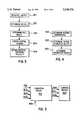
- FIG. 3is a flow chart illustrating a method according to an exemplary embodiment of the invention.
- FIG. 4is a flow chart illustrating a method according to other exemplary embodiments of the invention.
- FIG. 5shows a computing device for receiving measured quantities and for determining various quantities indicative of driving characteristics according to one or more exemplary embodiments of the present invention.
- the transverse-force build-up on the tiresmay be defined as the potential energy build-up in the tires of the vehicle caused by a time lag between the time the tires are turned and when the turn is felt due to the deformation of the tires.
- a modelling of this transverse-force build-up on the tiresis carried out according to the following equations: ##EQU1##
- the steering angle ⁇ , the longitudinal speed of the vehicle v and two transverse accelerations a qv and a qhwill now be used as measurement quantities.
- the two transverse-acceleration sensorscan each be described by the distance from the front axle and by the respective height. In view of the geometry, the following is obtained for these two acceleration sensors:
- Equation (10) and (11)relate to a system of two equations which are linearly independent in that l h is unequal to l v , consequently, with a known or negligible rolling acceleration d 2 ⁇ /dt 2 , the yaw-angle acceleration d 2 ⁇ /dt 2 and the transverse acceleration of the vehicle can be determined. Combining the two equations (10) and (11) produces: ##EQU2##
- the rolling dynamicscan be obtained by means of a numerical evaluation, known per se, of the differential equation (3), for example by means of the Runge-Kutta method or by means of the explicit Euler method with the integration step size ⁇ t: ##EQU3##
- the yaw-angle and transverse accelerations and the rolling quantitiescan thus be determined by using the equations (12), (13), (14) and (15) or by estimations of state by means of the equations (3), (10) and (11).
- Equations (4), (5), (6) and (7)thus produce two linear equations, by means of which the quantities v q and d ⁇ /dt can be determined from known quantities. ##EQU6##
- the equations (16) , (17) , (18) and (19)contain only quantities which are measured directly ( ⁇ , v, a gh , a qv ) or, as described above, can be determined by means of the measured quantities. Time derivations of known quantities can be derived by quotient formation. The quantities v g and d ⁇ /dt can thus be calculated at any time.
- the sideslip angle ⁇is obtained by the equation:
- the yaw-angle velocityis obtained from the equations (20) and (21) by the elimination of v q .
- the lateral forcesare calculated by means of the equations (16), (17), (18) and (19) and corresponding difference quotients.
- Actual estimated valuesare thus obtained for the cornering stiffness at the front and at the rear respectively.
- An updating of the values of the cornering stiffness which are used in the further calculationscan be carried out by L 2 , approximation with sliding time averaging.
- the parameters to be used in the following calculationsare designated by c v ,act and C h ,act.
- the previous parametersare designated by c v and by c h .
- the actual estimated valuesare designated by C v (t) and by C h (t).
- FIG. 3shows a possible flow of the method according to the invention.
- a first step 301measures the values, on the basis of which the quantities characterizing the driving behavior are determined. These values are the steering angle ⁇ , the longitudinal speed of the vehicle v and the two transverse accelerations a qv and a qh .
- the steering angle ⁇is preferably measured directly, and the longitudinal speed of the vehicle v can be determined, for example, from the signals of revolution sensors.
- the two transverse accelerations a qv , a qhare preferably measured directly by suitably mounted transverse- acceleration sensors.
- the transverse acceleration a q and the yaw-angle. acceleration d 2 ⁇ /dt 2are determined from these quantities, for example, by means of the equations (12) and (13).
- the roll angle ⁇ with its time derivationsis determined, for example by means of the equations (14) and (15). The higher derivations of the state quantities, which are also required below, are then formed by means of difference quotients.
- step 401higher derivations of the lateral forces are first determined by means of difference quotients. Actual estimated values of the parameters are then determined in a step 402 by means of the equations (23), (24), (25) and (26). Then, in a step 403, values of the parameters which, in the calculations which then follow, are used to determine quantities characterizing the driving behavior are determined by means of the equations (27) and (28).
- FIG. 5shows a computing device 501, to which the said quantities are fed, according to the step 301 shown in FIG. 3, as input signals 502, 503, 504, 505 representing the steering angle, the longitudinal speed of the vehicle, and the two transverse accelerations.
- output signals 506, 507, 508representing specific quantities are outputted to a vehicle control device 600.
- These specific quantitiescan be the sideslip angle, the yaw-angle velocity and/or a further quantity which is determined by the method.
- an adaptation of the parameters, by means of which the vehicle model is described,takes place according to the flow diagram of FIG. 4.
- the vehicle control device 600influences the driving behavior of the vehicle as a function of the yaw-angle velocity.
- the control device 600can be any of a number of different types of control devices that can use the yaw-angle velocity in a control of driving behavior. Examples of such control devices 600 are steering angle controls (U.S. Pat. No. 4,690,431); suspension controls (U.S. Pat. No. 5,208,749); and brake and traction control systems, such as shown in U.S. Pat. No. 4,988,593. All of these known controls use a signal representing yaw-angle velocity to control the driving behavior of a vehicle.
Landscapes
- Engineering & Computer Science (AREA)
- Transportation (AREA)
- Mechanical Engineering (AREA)
- Chemical & Material Sciences (AREA)
- Combustion & Propulsion (AREA)
- Aviation & Aerospace Engineering (AREA)
- Radar, Positioning & Navigation (AREA)
- Remote Sensing (AREA)
- Physics & Mathematics (AREA)
- General Physics & Mathematics (AREA)
- Automation & Control Theory (AREA)
- Steering Control In Accordance With Driving Conditions (AREA)
Abstract
Description
______________________________________ Symbol Meaning ______________________________________ d#/dt First derivative of a quantity #, which is one of the quantities contained in this table d.sup.2 #/dt.sup.2 Second derivative of a quantity # of which is one of the quantities contained in this table a Longitudinal acceleration of the vehicle a.sub.q Transverse acceleration of the vehicle a.sub.qh Transverse acceleration of the vehicle, rear a.sub.qv Transverse acceleration of the vehicle, front c.sub.h Cornering stiffness, rear c.sub.v Cornering stiffness, front cs.sub.h Transverse spring rigidity, rear cs.sub.v Transverse spring rigidity, front c.sub.x Torsion spring rigidity during rolling about longitudinal axis of vehicle h.sub.h Installation height of transverse-acceleration sensor, rear h.sub.p Rolling-pole height (distance between the point of fixed location and the ground during a rolling movement) h.sub.s Height of center of gravity h.sub.v Installation height of transverse-acceleration sensor, front J.sub.x Moment of inertia about the longitudinal axis of the vehicle J.sub.z Moment of inertia about the vertical axis of the vehicle k.sub.x Rotational damping during a rolling movement along the longitudinal axis of the vehicle l Wheelbase l.sub.h Distance between transverse-acceleration sensor, rear, and front axle l.sub.v Distance between transverse-acceleration sensor, front, and front axle l.sub.s Distance between center of gravity and front axle m Vehicle mass S.sub.h Lateral force on the rear wheels S.sub.v Lateral force on the front wheels v Longitudinal speed of the vehicle α.sub.h Slip angle on rear axle α.sub.v Slip angle on front axle β Sideslip angle δ Wheel steering angle δt Integration step size Φ Yaw angle τ Roll angle ______________________________________
m*a.sub.g =S.sub.v *cos (δ)+S.sub.h (1)
J.sub.z *d.sup.2 Φ/dt.sup.2 =l.sub.s *S.sub.v cos(δ)-(l-l.sub.s)*S.sub.h (2)
J.sub.x *d.sup.2 τ/dt.sup.2 +k.sub.x *dτ/dt+c.sub.x *τ=m*(h.sub.s -h.sub.p)*a.sub.q (3)
a.sub.q =dv.sub.q /dt+v*dΦ/dt (8)
a=dv/dt-v.sub.q *dΦ/dt (9)
a.sub.qv =a.sub.q +(l.sub.s -l.sub.v)*d.sup.2 Φ/dt.sup.2 +(h.sub.s -h.sub.v)*d.sup.2 τ/dt.sup.2 (10)
a.sub.qh =a.sub.q +(l.sub.s -l.sub.h)*d.sup.2 Φ/dt.sup.2 +(h.sub.s -h.sub.h)*d.sup.2 τ/dt.sup.2 (11)
β=arctan (v.sub.q /v) (22)
C.sub.v,act =(l-Γ)*c.sub.v +Γ*C.sub.v (t) (27)
C.sub.h,act =(l-Γ)*c.sub.h Γ*C.sub.h (t) (28)
Claims (20)
Priority Applications (1)
| Application Number | Priority Date | Filing Date | Title |
|---|---|---|---|
| US08/322,530US5548536A (en) | 1992-05-16 | 1994-10-17 | Method for determining quantities which characterize the driving behavior |
Applications Claiming Priority (4)
| Application Number | Priority Date | Filing Date | Title |
|---|---|---|---|
| DE4216301ADE4216301C2 (en) | 1992-05-16 | 1992-05-16 | Method for determining the behavior of characterizing variables |
| DE4216301.3 | 1992-05-16 | ||
| US6054893A | 1993-05-13 | 1993-05-13 | |
| US08/322,530US5548536A (en) | 1992-05-16 | 1994-10-17 | Method for determining quantities which characterize the driving behavior |
Related Parent Applications (1)
| Application Number | Title | Priority Date | Filing Date |
|---|---|---|---|
| US6054893AContinuation-In-Part | 1992-05-16 | 1993-05-13 |
Publications (1)
| Publication Number | Publication Date |
|---|---|
| US5548536Atrue US5548536A (en) | 1996-08-20 |
Family
ID=25914891
Family Applications (1)
| Application Number | Title | Priority Date | Filing Date |
|---|---|---|---|
| US08/322,530Expired - LifetimeUS5548536A (en) | 1992-05-16 | 1994-10-17 | Method for determining quantities which characterize the driving behavior |
Country Status (1)
| Country | Link |
|---|---|
| US (1) | US5548536A (en) |
Cited By (61)
| Publication number | Priority date | Publication date | Assignee | Title |
|---|---|---|---|---|
| US5694321A (en) | 1994-11-25 | 1997-12-02 | Itt Automotive Europe Gmbh | System for integrated driving stability control |
| US5711024A (en) | 1994-11-25 | 1998-01-20 | Itt Automotive Europe Gmbh | System for controlling yaw moment based on an estimated coefficient of friction |
| US5710704A (en) | 1994-11-25 | 1998-01-20 | Itt Automotive Europe Gmbh | System for driving stability control during travel through a curve |
| US5711023A (en) | 1994-11-25 | 1998-01-20 | Itt Automotive Europe Gmbh | System for determining side slip angle |
| US5710705A (en) | 1994-11-25 | 1998-01-20 | Itt Automotive Europe Gmbh | Method for determining an additional yawing moment based on side slip angle velocity |
| US5732378A (en) | 1994-11-25 | 1998-03-24 | Itt Automotive Europe Gmbh | Method for determining a wheel brake pressure |
| US5732377A (en) | 1994-11-25 | 1998-03-24 | Itt Automotive Europe Gmbh | Process for controlling driving stability with a yaw rate sensor equipped with two lateral acceleration meters |
| US5732379A (en) | 1994-11-25 | 1998-03-24 | Itt Automotive Europe Gmbh | Brake system for a motor vehicle with yaw moment control |
| US5742507A (en) | 1994-11-25 | 1998-04-21 | Itt Automotive Europe Gmbh | Driving stability control circuit with speed-dependent change of the vehicle model |
| US5758299A (en)* | 1995-11-03 | 1998-05-26 | Caterpillar Inc. | Method for generating performance ratings for a vehicle operator |
| US5774821A (en) | 1994-11-25 | 1998-06-30 | Itt Automotive Europe Gmbh | System for driving stability control |
| FR2807836A1 (en)* | 2000-04-18 | 2001-10-19 | Michelin Soc Tech | Method of regulation of the stability control system of an automobile vehicle, based on the existing stress at the center of each wheel of the vehicle |
| EP1147960A1 (en)* | 2000-04-18 | 2001-10-24 | Société de Technologie Michelin | Vehicle stability control method using tyre lateral forces |
| EP1110835A3 (en)* | 1999-12-21 | 2002-08-14 | Ford Global Technologies, Inc. | Roll over stability control for an automotive vehicle |
| EP1110834A3 (en)* | 1999-12-21 | 2002-08-14 | Ford Global Technologies, Inc. | Roll over stability control for an automotive vehicle |
| JP3341158B2 (en) | 1998-04-28 | 2002-11-05 | ダイムラークライスラー・アクチェンゲゼルシャフト | Method and apparatus for detecting and detecting sensor defects in automobiles |
| US6526334B1 (en)* | 1996-06-13 | 2003-02-25 | Continental Teves Ag & Co., Ohg | Method of controlling vehicle handling |
| US20030093206A1 (en)* | 2001-10-17 | 2003-05-15 | Patrick Pallot | Method and system for regulating a stability control system of a vehicle |
| US20030093207A1 (en)* | 2001-10-17 | 2003-05-15 | Patric Pallot | Method and system for regulating a stability control system in a vehicle |
| US20040064237A1 (en)* | 2002-08-01 | 2004-04-01 | Jianbo Lu | System and method for characterizing vehicle body to road angle for vehicle roll stability control |
| US20040117085A1 (en)* | 2001-11-21 | 2004-06-17 | Jianbo Lu | Enhanced system for yaw stability control system to include roll stability control function |
| US6834218B2 (en) | 2001-11-05 | 2004-12-21 | Ford Global Technologies, Llc | Roll over stability control for an automotive vehicle |
| US6904350B2 (en) | 2000-09-25 | 2005-06-07 | Ford Global Technologies, Llc | System for dynamically determining the wheel grounding and wheel lifting conditions and their applications in roll stability control |
| US20050154513A1 (en)* | 2004-01-14 | 2005-07-14 | Mitsubishi Denki Kabushiki Kaisha | Vehicle dynamics behavior reproduction system |
| US6941205B2 (en) | 2002-08-01 | 2005-09-06 | Ford Global Technologies, Llc. | System and method for deteching roll rate sensor fault |
| US6961648B2 (en) | 2002-08-05 | 2005-11-01 | Ford Motor Company | System and method for desensitizing the activation criteria of a rollover control system |
| US6963797B2 (en) | 2002-08-05 | 2005-11-08 | Ford Global Technologies, Llc | System and method for determining an amount of control for operating a rollover control system |
| US7079928B2 (en) | 2002-08-01 | 2006-07-18 | Ford Global Technologies, Llc | System and method for determining a wheel departure angle for a rollover control system with respect to road roll rate and loading misalignment |
| US7085639B2 (en) | 2002-08-01 | 2006-08-01 | Ford Global Technologies, Llc | System and method for characterizing the road bank for vehicle roll stability control |
| US7085642B2 (en) | 2002-08-05 | 2006-08-01 | Ford Global Technologies, Llc | Method and system for correcting sensor offsets |
| US7096103B2 (en) | 2002-08-05 | 2006-08-22 | Ford Motor Company | System and method for operating a rollover control system during an elevated condition |
| US7109856B2 (en) | 2000-09-25 | 2006-09-19 | Ford Global Technologies, Llc | Wheel lifted and grounded identification for an automotive vehicle |
| US7120528B2 (en) | 2002-08-05 | 2006-10-10 | Ford Global Technologies, Llc | System and method for operating a rollover control system in a transition to a rollover condition |
| US7132937B2 (en) | 2000-09-25 | 2006-11-07 | Ford Global Technologies, Llc | Wheel lift identification for an automotive vehicle using passive and active detection |
| US7136731B2 (en) | 2003-06-11 | 2006-11-14 | Ford Global Technologies, Llc | System for determining vehicular relative roll angle during a potential rollover event |
| US7194351B2 (en) | 2002-08-01 | 2007-03-20 | Ford Global Technologies, Llc | System and method for determining a wheel departure angle for a rollover control system |
| US7233236B2 (en) | 2000-09-25 | 2007-06-19 | Ford Global Technologies, Llc | Passive wheel lift identification for an automotive vehicle using operating input torque to wheel |
| US7239949B2 (en) | 2003-02-26 | 2007-07-03 | Ford Global Technologies, Llc | Integrated sensing system |
| US7278511B1 (en) | 2003-01-27 | 2007-10-09 | Polaris Industries Inc. | Controller for steering a vehicle |
| US7302331B2 (en) | 2002-08-01 | 2007-11-27 | Ford Global Technologies, Inc. | Wheel lift identification for an automotive vehicle |
| US7308350B2 (en) | 2004-05-20 | 2007-12-11 | Ford Global Technologies, Llc | Method and apparatus for determining adaptive brake gain parameters for use in a safety system of an automotive vehicle |
| US7316288B1 (en) | 2003-01-27 | 2008-01-08 | Polaris Industries Inc. | All terrain vehicle with multiple steering modes |
| USRE40268E1 (en) | 2000-09-25 | 2008-04-29 | Ford Global Technologies, Llc | Wheel lift identification for an automotive vehicle |
| USRE40496E1 (en) | 2002-03-04 | 2008-09-09 | Ford Global Technologies, Llc | Attitude sensing system for an automotive vehicle relative to the road |
| US7430468B2 (en) | 2002-08-05 | 2008-09-30 | Ford Global Technologies, Llc | System and method for sensitizing the activation criteria of a rollover control system |
| US7451032B2 (en) | 2004-06-02 | 2008-11-11 | Ford Global Technologies, Llc | System and method for determining desired yaw rate and lateral velocity for use in a vehicle dynamic control system |
| US7480547B2 (en) | 2005-04-14 | 2009-01-20 | Ford Global Technologies, Llc | Attitude sensing system for an automotive vehicle relative to the road |
| US7590481B2 (en) | 2005-09-19 | 2009-09-15 | Ford Global Technologies, Llc | Integrated vehicle control system using dynamically determined vehicle conditions |
| US7600826B2 (en) | 2005-11-09 | 2009-10-13 | Ford Global Technologies, Llc | System for dynamically determining axle loadings of a moving vehicle using integrated sensing system and its application in vehicle dynamics controls |
| US7640081B2 (en) | 2004-10-01 | 2009-12-29 | Ford Global Technologies, Llc | Roll stability control using four-wheel drive |
| US7653471B2 (en) | 2003-02-26 | 2010-01-26 | Ford Global Technologies, Llc | Active driven wheel lift identification for an automotive vehicle |
| US7660654B2 (en) | 2004-12-13 | 2010-02-09 | Ford Global Technologies, Llc | System for dynamically determining vehicle rear/trunk loading for use in a vehicle control system |
| US7668645B2 (en) | 2004-10-15 | 2010-02-23 | Ford Global Technologies | System and method for dynamically determining vehicle loading and vertical loading distance for use in a vehicle dynamic control system |
| US7715965B2 (en) | 2004-10-15 | 2010-05-11 | Ford Global Technologies | System and method for qualitatively determining vehicle loading conditions |
| US20100161178A1 (en)* | 2006-05-10 | 2010-06-24 | Toyota Jidosha Kabushiki Kaisha | Vehicular steering control device |
| US8121758B2 (en) | 2005-11-09 | 2012-02-21 | Ford Global Technologies | System for determining torque and tire forces using integrated sensing system |
| US8595034B2 (en) | 1996-01-29 | 2013-11-26 | Progressive Casualty Insurance Company | Monitoring system for determining and communicating a cost of insurance |
| US8892451B2 (en) | 1996-01-29 | 2014-11-18 | Progressive Casualty Insurance Company | Vehicle monitoring system |
| US9162656B2 (en) | 2003-02-26 | 2015-10-20 | Ford Global Technologies, Llc | Active driven wheel lift identification for an automotive vehicle |
| US11030702B1 (en) | 2012-02-02 | 2021-06-08 | Progressive Casualty Insurance Company | Mobile insurance platform system |
| CN115406451A (en)* | 2022-11-01 | 2022-11-29 | 联友智连科技有限公司 | Vehicle positioning method, system, vehicle terminal and storage medium |
Citations (9)
| Publication number | Priority date | Publication date | Assignee | Title |
|---|---|---|---|---|
| US4412594A (en)* | 1980-08-27 | 1983-11-01 | Honda Giken Kogyo Kabushiki Kaisha | Steering system for motor vehicles |
| DE3608420A1 (en)* | 1985-03-15 | 1986-09-25 | Nissan Motor Co., Ltd., Yokohama, Kanagawa | DEVICE FOR DETERMINING THE MOVEMENT OF A VEHICLE |
| DE3642049A1 (en)* | 1985-12-09 | 1987-06-11 | Nissan Motor | CONTROL SYSTEM FOR VEHICLE STEERING WITH PARAMETER DETECTION |
| US4964481A (en)* | 1984-01-13 | 1990-10-23 | Honda Giken Kogyo Kabushiki Kaisha | Steering system for vehicles |
| DE4132276A1 (en)* | 1990-09-27 | 1992-04-09 | Fuji Heavy Ind Ltd | METHOD AND SYSTEM FOR MONITORING ACTIVE SUSPENSIONS FOR A VEHICLE |
| GB2257551A (en)* | 1991-07-12 | 1993-01-13 | Bosch Gmbh Robert | Determination of a parameter of motion of a vehicle |
| US5208751A (en)* | 1988-04-19 | 1993-05-04 | Dr. Ing. H.C.F. Porsche Ag | Active four-wheel steering system for motor vehicles |
| US5386365A (en)* | 1991-03-22 | 1995-01-31 | Mazda Motor Corporation | Rear wheel steering system for vehicle |
| US5388626A (en)* | 1991-06-17 | 1995-02-14 | Sumitomo Rubber Industries, Ltd. | Radial tire |
- 1994
- 1994-10-17USUS08/322,530patent/US5548536A/ennot_activeExpired - Lifetime
Patent Citations (9)
| Publication number | Priority date | Publication date | Assignee | Title |
|---|---|---|---|---|
| US4412594A (en)* | 1980-08-27 | 1983-11-01 | Honda Giken Kogyo Kabushiki Kaisha | Steering system for motor vehicles |
| US4964481A (en)* | 1984-01-13 | 1990-10-23 | Honda Giken Kogyo Kabushiki Kaisha | Steering system for vehicles |
| DE3608420A1 (en)* | 1985-03-15 | 1986-09-25 | Nissan Motor Co., Ltd., Yokohama, Kanagawa | DEVICE FOR DETERMINING THE MOVEMENT OF A VEHICLE |
| DE3642049A1 (en)* | 1985-12-09 | 1987-06-11 | Nissan Motor | CONTROL SYSTEM FOR VEHICLE STEERING WITH PARAMETER DETECTION |
| US5208751A (en)* | 1988-04-19 | 1993-05-04 | Dr. Ing. H.C.F. Porsche Ag | Active four-wheel steering system for motor vehicles |
| DE4132276A1 (en)* | 1990-09-27 | 1992-04-09 | Fuji Heavy Ind Ltd | METHOD AND SYSTEM FOR MONITORING ACTIVE SUSPENSIONS FOR A VEHICLE |
| US5386365A (en)* | 1991-03-22 | 1995-01-31 | Mazda Motor Corporation | Rear wheel steering system for vehicle |
| US5388626A (en)* | 1991-06-17 | 1995-02-14 | Sumitomo Rubber Industries, Ltd. | Radial tire |
| GB2257551A (en)* | 1991-07-12 | 1993-01-13 | Bosch Gmbh Robert | Determination of a parameter of motion of a vehicle |
Non-Patent Citations (2)
| Title |
|---|
| Zomotor, Adam: Fahrwerktechnik, Fahrverhalten, (Chassis technology driving behavior), Vogel 1987, IBN 3 8023 0774 7, pp. 99 116.* |
| Zomotor, Adam: Fahrwerktechnik, Fahrverhalten, (Chassis technology driving behavior), Vogel 1987, IBN 3-8023-0774-7, pp. 99-116. |
Cited By (87)
| Publication number | Priority date | Publication date | Assignee | Title |
|---|---|---|---|---|
| US5732379A (en) | 1994-11-25 | 1998-03-24 | Itt Automotive Europe Gmbh | Brake system for a motor vehicle with yaw moment control |
| US5694321A (en) | 1994-11-25 | 1997-12-02 | Itt Automotive Europe Gmbh | System for integrated driving stability control |
| US5710704A (en) | 1994-11-25 | 1998-01-20 | Itt Automotive Europe Gmbh | System for driving stability control during travel through a curve |
| US5711023A (en) | 1994-11-25 | 1998-01-20 | Itt Automotive Europe Gmbh | System for determining side slip angle |
| US5710705A (en) | 1994-11-25 | 1998-01-20 | Itt Automotive Europe Gmbh | Method for determining an additional yawing moment based on side slip angle velocity |
| US5711025A (en) | 1994-11-25 | 1998-01-20 | Itt Automotive Europe Gmbh | Driving stability control system with selective brake actuation |
| US5732378A (en) | 1994-11-25 | 1998-03-24 | Itt Automotive Europe Gmbh | Method for determining a wheel brake pressure |
| US5732377A (en) | 1994-11-25 | 1998-03-24 | Itt Automotive Europe Gmbh | Process for controlling driving stability with a yaw rate sensor equipped with two lateral acceleration meters |
| US5711024A (en) | 1994-11-25 | 1998-01-20 | Itt Automotive Europe Gmbh | System for controlling yaw moment based on an estimated coefficient of friction |
| US5862503A (en) | 1994-11-25 | 1999-01-19 | Itt Automotive Europe Gmbh | System for driving stability control |
| US5742507A (en) | 1994-11-25 | 1998-04-21 | Itt Automotive Europe Gmbh | Driving stability control circuit with speed-dependent change of the vehicle model |
| US5774821A (en) | 1994-11-25 | 1998-06-30 | Itt Automotive Europe Gmbh | System for driving stability control |
| US5758299A (en)* | 1995-11-03 | 1998-05-26 | Caterpillar Inc. | Method for generating performance ratings for a vehicle operator |
| US8892451B2 (en) | 1996-01-29 | 2014-11-18 | Progressive Casualty Insurance Company | Vehicle monitoring system |
| US9754424B2 (en) | 1996-01-29 | 2017-09-05 | Progressive Casualty Insurance Company | Vehicle monitoring system |
| US8595034B2 (en) | 1996-01-29 | 2013-11-26 | Progressive Casualty Insurance Company | Monitoring system for determining and communicating a cost of insurance |
| US6526334B1 (en)* | 1996-06-13 | 2003-02-25 | Continental Teves Ag & Co., Ohg | Method of controlling vehicle handling |
| JP3341158B2 (en) | 1998-04-28 | 2002-11-05 | ダイムラークライスラー・アクチェンゲゼルシャフト | Method and apparatus for detecting and detecting sensor defects in automobiles |
| EP1110834A3 (en)* | 1999-12-21 | 2002-08-14 | Ford Global Technologies, Inc. | Roll over stability control for an automotive vehicle |
| EP1110835A3 (en)* | 1999-12-21 | 2002-08-14 | Ford Global Technologies, Inc. | Roll over stability control for an automotive vehicle |
| US7130735B2 (en) | 1999-12-21 | 2006-10-31 | Ford Global Technologies, Llc | Roll over stability control for an automotive vehicle |
| US6604036B2 (en) | 2000-04-18 | 2003-08-05 | Michelin Recherche Et Technique S.A. | Method for controlling the stability of a vehicle based on lateral forces exerted on each wheel |
| FR2807836A1 (en)* | 2000-04-18 | 2001-10-19 | Michelin Soc Tech | Method of regulation of the stability control system of an automobile vehicle, based on the existing stress at the center of each wheel of the vehicle |
| EP1147960A1 (en)* | 2000-04-18 | 2001-10-24 | Société de Technologie Michelin | Vehicle stability control method using tyre lateral forces |
| US7109856B2 (en) | 2000-09-25 | 2006-09-19 | Ford Global Technologies, Llc | Wheel lifted and grounded identification for an automotive vehicle |
| US6904350B2 (en) | 2000-09-25 | 2005-06-07 | Ford Global Technologies, Llc | System for dynamically determining the wheel grounding and wheel lifting conditions and their applications in roll stability control |
| USRE40268E1 (en) | 2000-09-25 | 2008-04-29 | Ford Global Technologies, Llc | Wheel lift identification for an automotive vehicle |
| US7233236B2 (en) | 2000-09-25 | 2007-06-19 | Ford Global Technologies, Llc | Passive wheel lift identification for an automotive vehicle using operating input torque to wheel |
| US7132937B2 (en) | 2000-09-25 | 2006-11-07 | Ford Global Technologies, Llc | Wheel lift identification for an automotive vehicle using passive and active detection |
| US6859713B2 (en) | 2001-10-17 | 2005-02-22 | Michelin Recherche Et Technique | Method and system for regulating a stability control system of a vehicle |
| US20030093206A1 (en)* | 2001-10-17 | 2003-05-15 | Patrick Pallot | Method and system for regulating a stability control system of a vehicle |
| US20030093207A1 (en)* | 2001-10-17 | 2003-05-15 | Patric Pallot | Method and system for regulating a stability control system in a vehicle |
| US6834218B2 (en) | 2001-11-05 | 2004-12-21 | Ford Global Technologies, Llc | Roll over stability control for an automotive vehicle |
| US7136730B2 (en) | 2001-11-21 | 2006-11-14 | Ford Global Technologies, Llc | Enhanced system for yaw stability control system to include roll stability control function |
| US7027902B2 (en) | 2001-11-21 | 2006-04-11 | Ford Global Technologies, Llc | Enhanced system for yaw stability control system to include roll stability control function |
| US20040117085A1 (en)* | 2001-11-21 | 2004-06-17 | Jianbo Lu | Enhanced system for yaw stability control system to include roll stability control function |
| USRE40496E1 (en) | 2002-03-04 | 2008-09-09 | Ford Global Technologies, Llc | Attitude sensing system for an automotive vehicle relative to the road |
| US7194351B2 (en) | 2002-08-01 | 2007-03-20 | Ford Global Technologies, Llc | System and method for determining a wheel departure angle for a rollover control system |
| US7085639B2 (en) | 2002-08-01 | 2006-08-01 | Ford Global Technologies, Llc | System and method for characterizing the road bank for vehicle roll stability control |
| US7079928B2 (en) | 2002-08-01 | 2006-07-18 | Ford Global Technologies, Llc | System and method for determining a wheel departure angle for a rollover control system with respect to road roll rate and loading misalignment |
| US7003389B2 (en) | 2002-08-01 | 2006-02-21 | Ford Global Technologies, Llc | System and method for characterizing vehicle body to road angle for vehicle roll stability control |
| US6941205B2 (en) | 2002-08-01 | 2005-09-06 | Ford Global Technologies, Llc. | System and method for deteching roll rate sensor fault |
| US7302331B2 (en) | 2002-08-01 | 2007-11-27 | Ford Global Technologies, Inc. | Wheel lift identification for an automotive vehicle |
| US20040064237A1 (en)* | 2002-08-01 | 2004-04-01 | Jianbo Lu | System and method for characterizing vehicle body to road angle for vehicle roll stability control |
| US6963797B2 (en) | 2002-08-05 | 2005-11-08 | Ford Global Technologies, Llc | System and method for determining an amount of control for operating a rollover control system |
| US6961648B2 (en) | 2002-08-05 | 2005-11-01 | Ford Motor Company | System and method for desensitizing the activation criteria of a rollover control system |
| US7430468B2 (en) | 2002-08-05 | 2008-09-30 | Ford Global Technologies, Llc | System and method for sensitizing the activation criteria of a rollover control system |
| US7277787B2 (en) | 2002-08-05 | 2007-10-02 | Ford Motor Company | System and method for desensitizing the activation criteria of a rollover control system |
| US7120528B2 (en) | 2002-08-05 | 2006-10-10 | Ford Global Technologies, Llc | System and method for operating a rollover control system in a transition to a rollover condition |
| US7085642B2 (en) | 2002-08-05 | 2006-08-01 | Ford Global Technologies, Llc | Method and system for correcting sensor offsets |
| US7096103B2 (en) | 2002-08-05 | 2006-08-22 | Ford Motor Company | System and method for operating a rollover control system during an elevated condition |
| US7278511B1 (en) | 2003-01-27 | 2007-10-09 | Polaris Industries Inc. | Controller for steering a vehicle |
| US7316288B1 (en) | 2003-01-27 | 2008-01-08 | Polaris Industries Inc. | All terrain vehicle with multiple steering modes |
| US7653471B2 (en) | 2003-02-26 | 2010-01-26 | Ford Global Technologies, Llc | Active driven wheel lift identification for an automotive vehicle |
| US7239949B2 (en) | 2003-02-26 | 2007-07-03 | Ford Global Technologies, Llc | Integrated sensing system |
| US9162656B2 (en) | 2003-02-26 | 2015-10-20 | Ford Global Technologies, Llc | Active driven wheel lift identification for an automotive vehicle |
| US7136731B2 (en) | 2003-06-11 | 2006-11-14 | Ford Global Technologies, Llc | System for determining vehicular relative roll angle during a potential rollover event |
| US7184868B2 (en)* | 2004-01-14 | 2007-02-27 | Mitsubishi Denki Kabushiki Kaisha | Vehicle dynamics behavior reproduction system |
| US20050154513A1 (en)* | 2004-01-14 | 2005-07-14 | Mitsubishi Denki Kabushiki Kaisha | Vehicle dynamics behavior reproduction system |
| US7308350B2 (en) | 2004-05-20 | 2007-12-11 | Ford Global Technologies, Llc | Method and apparatus for determining adaptive brake gain parameters for use in a safety system of an automotive vehicle |
| US7451032B2 (en) | 2004-06-02 | 2008-11-11 | Ford Global Technologies, Llc | System and method for determining desired yaw rate and lateral velocity for use in a vehicle dynamic control system |
| US7640081B2 (en) | 2004-10-01 | 2009-12-29 | Ford Global Technologies, Llc | Roll stability control using four-wheel drive |
| US7877201B2 (en) | 2004-10-15 | 2011-01-25 | Ford Global Technologies | System and method for dynamically determining vehicle loading and vertical loading distance for use in a vehicle dynamic control system |
| US7668645B2 (en) | 2004-10-15 | 2010-02-23 | Ford Global Technologies | System and method for dynamically determining vehicle loading and vertical loading distance for use in a vehicle dynamic control system |
| US7877178B2 (en) | 2004-10-15 | 2011-01-25 | Ford Global Technologies | System and method for dynamically determining vehicle loading and vertical loading distance for use in a vehicle dynamic control system |
| US7877199B2 (en) | 2004-10-15 | 2011-01-25 | Ford Global Technologies | System and method for dynamically determining vehicle loading and vertical loading distance for use in a vehicle dynamic control system |
| US7715965B2 (en) | 2004-10-15 | 2010-05-11 | Ford Global Technologies | System and method for qualitatively determining vehicle loading conditions |
| US7877200B2 (en) | 2004-10-15 | 2011-01-25 | Ford Global Technologies | System and method for dynamically determining vehicle loading and vertical loading distance for use in a vehicle dynamic control system |
| US7899594B2 (en) | 2004-10-15 | 2011-03-01 | Ford Global Technologies | System and method for qualitatively determining vehicle loading conditions |
| US8050857B2 (en) | 2004-10-15 | 2011-11-01 | Ford Global Technologies | System and method for dynamically determining vehicle loading and vertical loading distance for use in a vehicle dynamic control system |
| US8219282B2 (en) | 2004-12-13 | 2012-07-10 | Ford Global Technologies | System for dynamically determining vehicle rear/trunk loading for use in a vehicle control system |
| US8005596B2 (en) | 2004-12-13 | 2011-08-23 | Ford Global Technologies | System for dynamically determining vehicle rear/trunk loading for use in a vehicle control system |
| US8346433B2 (en) | 2004-12-13 | 2013-01-01 | Ford Global Technologies | System for dynamically determining vehicle rear/trunk loading for use in a vehicle control system |
| US7660654B2 (en) | 2004-12-13 | 2010-02-09 | Ford Global Technologies, Llc | System for dynamically determining vehicle rear/trunk loading for use in a vehicle control system |
| US7480547B2 (en) | 2005-04-14 | 2009-01-20 | Ford Global Technologies, Llc | Attitude sensing system for an automotive vehicle relative to the road |
| US8442720B2 (en) | 2005-09-19 | 2013-05-14 | Ford Global Technologies | Integrated vehicle control system using dynamically determined vehicle conditions |
| US8311706B2 (en) | 2005-09-19 | 2012-11-13 | Ford Global Technologies | Integrated vehicle control system using dynamically determined vehicle conditions |
| US7590481B2 (en) | 2005-09-19 | 2009-09-15 | Ford Global Technologies, Llc | Integrated vehicle control system using dynamically determined vehicle conditions |
| US8346452B2 (en) | 2005-09-19 | 2013-01-01 | Ford Global Technologies | Integrated vehicle control system using dynamically determined vehicle conditions |
| US8352143B2 (en) | 2005-09-19 | 2013-01-08 | Ford Global Technologies | Integrated vehicle control system using dynamically determined vehicle conditions |
| US8005592B2 (en) | 2005-11-09 | 2011-08-23 | Ford Global Technologies | System for dynamically determining axle loadings of a moving vehicle using integrated sensing system and its application in vehicle dynamics controls |
| US8121758B2 (en) | 2005-11-09 | 2012-02-21 | Ford Global Technologies | System for determining torque and tire forces using integrated sensing system |
| US7600826B2 (en) | 2005-11-09 | 2009-10-13 | Ford Global Technologies, Llc | System for dynamically determining axle loadings of a moving vehicle using integrated sensing system and its application in vehicle dynamics controls |
| US8200392B2 (en)* | 2006-05-10 | 2012-06-12 | Toyota Jidosha Kabushiki Kaisha | Vehicular steering control device |
| US20100161178A1 (en)* | 2006-05-10 | 2010-06-24 | Toyota Jidosha Kabushiki Kaisha | Vehicular steering control device |
| US11030702B1 (en) | 2012-02-02 | 2021-06-08 | Progressive Casualty Insurance Company | Mobile insurance platform system |
| CN115406451A (en)* | 2022-11-01 | 2022-11-29 | 联友智连科技有限公司 | Vehicle positioning method, system, vehicle terminal and storage medium |
Similar Documents
| Publication | Publication Date | Title |
|---|---|---|
| US5548536A (en) | Method for determining quantities which characterize the driving behavior | |
| US5557520A (en) | Method for determining variables characterizing vehicle handling | |
| US5742918A (en) | Method and apparatus for dynamically compensating a lateral acceleration of a motor vehicle | |
| GB2266957A (en) | Method of determining driving behaviour of a vehicle | |
| EP1346856B1 (en) | A system and method for determining the roll angle of a vehicle | |
| Tseng | Dynamic estimation of road bank angle | |
| US6526334B1 (en) | Method of controlling vehicle handling | |
| US8649938B2 (en) | System, program product, and method for dynamic control of vehicle | |
| CN102556075B (en) | Vehicle operating state estimation method based on improved extended Kalman filter | |
| US5878357A (en) | Method and apparatus for vehicle yaw rate estimation | |
| US6725140B2 (en) | Method and apparatus for determining lateral velocity of a motor vehicle in closed form for all road and driving conditions | |
| CN101007530B (en) | Apparatus and method for estimating a sideslip angle, automobile | |
| JPH06273187A (en) | Vehicle weight center slip angle measuring device | |
| EP0803386A1 (en) | A method and apparatus for dynamically determining an operating state of a motor vehicle | |
| US20030236603A1 (en) | System for sensing vehicle global and relative attitudes using suspension height sensors | |
| JPH06104455B2 (en) | Vehicle motion condition estimation device | |
| CN113799783B (en) | Road transverse gradient measuring method and system applied to vehicle | |
| US6138066A (en) | Method of determining quantities describing vehicle driving behavior | |
| GB2409914A (en) | Attitude sensing system for an automotive vehicle relative to the road. | |
| US5670872A (en) | System and device with vertical and rotary wheel-velocity-measuring for determining vehicle displacement | |
| JP7224897B2 (en) | Vehicle motion state estimation device, vehicle motion state estimation method, and vehicle | |
| KR19990082250A (en) | How to determine the amount to display the driving behavior of the vehicle | |
| JP2552380B2 (en) | Detection value offset amount remover | |
| US5515275A (en) | Control system for steering a road vehicle having both front-wheel steering and rear wheel steering | |
| US12330463B2 (en) | Vehicle suspension system |
Legal Events
| Date | Code | Title | Description |
|---|---|---|---|
| AS | Assignment | Owner name:DAIMLER-BENZ AG, GERMANY Free format text:ASSIGNMENT OF ASSIGNORS INTEREST;ASSIGNOR:AMMON, DIETER;REEL/FRAME:007168/0892 Effective date:19940928 | |
| STCF | Information on status: patent grant | Free format text:PATENTED CASE | |
| FEPP | Fee payment procedure | Free format text:PAYOR NUMBER ASSIGNED (ORIGINAL EVENT CODE: ASPN); ENTITY STATUS OF PATENT OWNER: LARGE ENTITY | |
| FPAY | Fee payment | Year of fee payment:4 | |
| FEPP | Fee payment procedure | Free format text:PAYOR NUMBER ASSIGNED (ORIGINAL EVENT CODE: ASPN); ENTITY STATUS OF PATENT OWNER: LARGE ENTITY Free format text:PAYER NUMBER DE-ASSIGNED (ORIGINAL EVENT CODE: RMPN); ENTITY STATUS OF PATENT OWNER: LARGE ENTITY | |
| FPAY | Fee payment | Year of fee payment:8 | |
| FPAY | Fee payment | Year of fee payment:12 | |
| AS | Assignment | Owner name:DAIMLERCHRYSLER AG, GERMANY Free format text:MERGER;ASSIGNOR:DAIMLER-BENZ AKTIENGESELLSCHAFT;REEL/FRAME:020930/0936 Effective date:19981221 | |
| AS | Assignment | Owner name:DAIMLER AG, GERMANY Free format text:CHANGE OF NAME;ASSIGNOR:DAIMLERCHRYSLER AG;REEL/FRAME:020976/0889 Effective date:20071019 Owner name:DAIMLER AG,GERMANY Free format text:CHANGE OF NAME;ASSIGNOR:DAIMLERCHRYSLER AG;REEL/FRAME:020976/0889 Effective date:20071019 | |
| AS | Assignment | Owner name:BAYERISCHE MOTOREN WERKE AKTIENGESELLSCHAFT, GERMA Free format text:ASSIGNMENT OF ASSIGNORS INTEREST;ASSIGNOR:DAIMLER AG;REEL/FRAME:028090/0731 Effective date:20120306 | |
| AS | Assignment | Owner name:DAIMLER AG, GERMANY Free format text:CORRECTIVE ASSIGNMENT TO CORRECT THE APPLICATION NO. 10/567,810 PREVIOUSLY RECORDED ON REEL 020976 FRAME 0889. ASSIGNOR(S) HEREBY CONFIRMS THE CHANGE OF NAME;ASSIGNOR:DAIMLERCHRYSLER AG;REEL/FRAME:053583/0493 Effective date:20071019 |