US5547374A - Rate controlled fluid delivery in dental applications - Google Patents
Rate controlled fluid delivery in dental applicationsDownload PDFInfo
- Publication number
- US5547374A US5547374AUS08/327,378US32737894AUS5547374AUS 5547374 AUS5547374 AUS 5547374AUS 32737894 AUS32737894 AUS 32737894AUS 5547374 AUS5547374 AUS 5547374A
- Authority
- US
- United States
- Prior art keywords
- dial
- flow passage
- barrel portion
- flow
- defining
- Prior art date
- Legal status (The legal status is an assumption and is not a legal conclusion. Google has not performed a legal analysis and makes no representation as to the accuracy of the status listed.)
- Expired - Lifetime
Links
- 239000012530fluidSubstances0.000titleclaimsabstractdescription42
- XLYOFNOQVPJJNP-UHFFFAOYSA-NwaterSubstancesOXLYOFNOQVPJJNP-UHFFFAOYSA-N0.000claimsdescription20
- 238000007373indentationMethods0.000claimsdescription13
- 238000013022ventingMethods0.000claimsdescription4
- 238000000034methodMethods0.000abstractdescription17
- 230000035945sensitivityEffects0.000description8
- 208000036372Sensitivity of teethDiseases0.000description3
- 238000012549trainingMethods0.000description3
- 210000003298dental enamelAnatomy0.000description2
- 239000000203mixtureSubstances0.000description2
- 238000004659sterilization and disinfectionMethods0.000description2
- 210000001036tooth cervixAnatomy0.000description2
- 229910001369BrassInorganic materials0.000description1
- XAGFODPZIPBFFR-UHFFFAOYSA-NaluminiumChemical compound[Al]XAGFODPZIPBFFR-UHFFFAOYSA-N0.000description1
- 229910052782aluminiumInorganic materials0.000description1
- 239000010951brassSubstances0.000description1
- 238000004140cleaningMethods0.000description1
- 238000012937correctionMethods0.000description1
- 238000005336crackingMethods0.000description1
- 230000037123dental healthEffects0.000description1
- 210000004268dentinAnatomy0.000description1
- 238000011156evaluationMethods0.000description1
- 230000003902lesionEffects0.000description1
- 239000000463materialSubstances0.000description1
- 239000012858resilient materialSubstances0.000description1
- 230000000717retained effectEffects0.000description1
- 238000010008shearingMethods0.000description1
- 239000007921spraySubstances0.000description1
- 229910001220stainless steelInorganic materials0.000description1
- 239000010935stainless steelSubstances0.000description1
- 230000001954sterilising effectEffects0.000description1
- 238000001356surgical procedureMethods0.000description1
Images

Classifications
- A—HUMAN NECESSITIES
- A61—MEDICAL OR VETERINARY SCIENCE; HYGIENE
- A61C—DENTISTRY; APPARATUS OR METHODS FOR ORAL OR DENTAL HYGIENE
- A61C17/00—Devices for cleaning, polishing, rinsing or drying teeth, teeth cavities or prostheses; Saliva removers; Dental appliances for receiving spittle
- A61C17/02—Rinsing or air-blowing devices, e.g. using fluid jets or comprising liquid medication
Definitions
- This inventionrelates to rate controlled fluid delivery in dental applications.
- a dental syringe delivering pressurized fluid to a wand tiphas been described in U.S. Pat. No. 4,249,899.
- Such syringesare typically used to deliver a spray of water and/or air to a specific location in a patient's mouth.
- the reduction to the volumeallows the novice operator to reduce flows and thereby limit unwanted splatter in clinical performance of dental procedures.
- the improvement of a dental syringecomprising an air source and a water source includes the addition of a fluid control block.
- the fluid control blockincludes a barrel portion having a first connector for attachment to a syringe handle and a second connector for attachment to a delivery nozzle.
- the barrel portiondefines a flow passage.
- a dialis rotatably mounted to the barrel portion and defines a plurality of differently sized flow orifices alignable one-at-a-time with the flow passage. Each of the flow orifices allows a predetermined level of fluid flow through the flow passage when aligned with the flow passage.
- the barrel portiondefines a slot in which the dial is rotatably mounted to the barrel portion.
- a pivot pinis included for rotatably mounting the dial to the barrel portion.
- the dialdefines a centrally located pivot hole for placement of the pivot pin therethrough and the barrel portion defines a centrally offset pivot hole wherein an end of the pivot pin is connected.
- the flow passageis centrally located in the barrel portion.
- the flow orificesare radially spaced about the centrally located pivot hole, the flow orifices being alignable with the flow passage by rotation of the dial about the pivot pin.
- a detent pinis included for preventing rotation of the dial about the pivot pin.
- the barrel portiondefines a detent hole for placement of the detent pin therein.
- the dialdefines a plurality of detent pin indentations, an end of the detent pin is located in one of the detent pin indentations when one of the flow orifices is aligned with the flow passage.
- the detent holeis located radially the same distance as the centrally located flow passage from the pivot pin, and each of the detent pin indentations is coaxially located about one of the flow orifices, one of the flow orifices being aligned with the flow passage when another of the flow orifices is aligned with the detent pin.
- the dialincludes a knurled edge for finger rotation of the dial and placement markers located on the knurled edge indicate the position of the flow orifices with respect to the flow passage.
- An o-ringis located in the flow passage on a first side of the dial between the barrel portion and the dial. Venting of excess pressure to atmosphere occurs around the o-ring.
- a second o-ringis located on the side of the dial opposite the first side between the dial and the barrel portion. Venting of excess pressure to atmosphere occurs around the second o-ring.
- the delivery nozzleis a wand tip.
- Another aspect of the inventiongenerally features a method of assessing abfraction.
- a controlled volume of airis delivered to teeth.
- the sensitivity of a tooth to the delivered fluidis determined.
- the sensitivityis used to identify and quantify abfraction forces acting upon the tooth.
- Another aspect of the inventiongenerally features a method of assessing the success or failure of an occlusal adjustment procedure.
- a controlled volume of airis delivered to teeth.
- the level of sensitivity of teeth to airis measured before an occlusal adjustment procedure.
- the level of sensitivity of teeth to airis measured after an occlusal adjustment procedure.
- the sensitivities measured before and after the occlusal adjustment procedureare compared with a decrease in sensitivity indicating an improved bite resulting from reduced abfraction forces.
- Another aspect of the inventiongenerally features a method of reducing splatter when using a dental syringe comprising an air source and a water source employing the fluid control block of the invention.
- the fluid control blockis attached to the syringe handle and the delivery nozzle.
- the dialis rotated to align a desired flow orifice with the flow passage, the desired flow orifice providing fluid flow at a fluid pressure below that provided by the sources.
- the fluid flowis delivered to a patient's mouth.
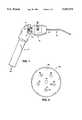
- FIG. 1is a diagrammatic representation of the fluid control block for controlled delivery of fluid from an air/water syringe to a wand tip;
- FIG. 2is a partially cut away side view of the fluid control block
- FIG. 2ais an end view of the fluid control block of FIG. 2 taken along the line 2a--2a, with the pivot pin and detent pin removed;
- FIG. 3shows the dial of the invention.
- fluid control block 10provides controlled delivery of fluid from a pressurized source, e.g., a standard dental air/water supply (not shown). Fluid control block 10 is attached at proximal end 16 to syringe handle 12 and at distal end 18 to a dental device, e.g., standard wand tip 14 currently in use in dentistry.
- a pressurized sourcee.g., a standard dental air/water supply (not shown).
- Fluid control block 10is attached at proximal end 16 to syringe handle 12 and at distal end 18 to a dental device, e.g., standard wand tip 14 currently in use in dentistry.
- Syringe handle 12includes an air conduit 15 and a water conduit 17. Valves (not shown) control the mixture of air/water that flows into fluid control block 10 (see Davis U.S. Pat. No. 4,249,899 and Lewis U.S. Pat. No. 4,248,589, hereby incorporated by reference).
- fluid control block 10includes barrel portion 20 and dial 40 constructed of materials acceptable for dental use in accordance with standard disinfection and/or sterilization techniques, e.g., stainless steel, anodized aluminum, brass or other resilient material.
- Barrel portion 20includes slot 21 having a width, e g, of 0.062" in which dial 40 is located.
- Barrel portion 20has a maximum diameter, e.g., of 0.62" and dial 40 has a diameter, e.g., of 0.604" and a thickness, e.g., of 0.06".
- Fluid control block 10defines a flow passage 38 aligned with an axis, A for fluid flow along arrow 70.
- a threaded hole 22 defined by barrel portion 20 at proximal end 16accepts male connector 72 which connects fluid control block 10 to syringe 12.
- a second threaded hole 24 defined by barrel portion 20 at distal end 18connects fluid control block 10 to wand tip 14.
- Barrel portion 20 and dial 40are rotatably connected via a pivot pin 26.
- Pivot pin 26is passed through centrally located hole 42 in dial 40 and screwed into place in the threaded portion of a hole 30 defined by barrel portion 20.
- a detent pine.g., spring loaded ball plunger 28, is positionable to prevent rotation of dial 40 about pivot pin 26.
- a hole 32 in barrel portion 20 and a plurality of detent indentations 44 in dial 40receive plunger 28. Detent indentations 44 go partially through the thickness of dial 40, e.g., 0.04" deep.
- Barrel portion 20defines two o-ring recesses 34, 34' for receiving o-rings 36, 36'.
- O-rings 36, 36'are retained in position on one side by frictional force against dial 40 and on the other by recesses 34, 34'.
- detent indentations 44are concentrically located about a plurality of flow orifices 46, 48, 50, 52 and 54 of varying diameters, e.g., 0.005", 0.0075", 0.0102", 0.0135" and 0.045" respectively, equally spaced about the center of dial 40.
- the diameter of flow orifice 54corresponds to the diameter of the syringe's flow passage to provide for a flow rate through fluid control block 10 equal to that of the flow rate through the syringe.
- the edge of dial 40includes serrations 45 for ease of finger pressure rotation and includes machined indentations 60 which serve as indicators of the position of the flow orifices with respect to flow passage 38 to facilitate alignment of a desired flow orifice in the flow passage.
- Incoming air pressure from a dental air/water supplyis commonly 20-50 P.S.I. Due to the sizes of the flow orifices in dial 40, incoming air pressure is great enough that excess pressure generally vents around o-ring 36. Due to this release, air pressure released into wand tip 14 from fluid control block 10 is as little as 2-3 P.S.I. with the smallest orifice 46 in place, approximately 14-17 P.S.I. with the third largest orifice 50 in place, and increases with larger orifices, the air pressure released into wand tip 14 with the largest orifice 54 in place being that of the supply pressure.
- Fluid control block 10may he easily disassembled hy removal of pivot pin 26 to allow cleaning or replacement of o-rings 36, 36'. Dial 40 may also he replaced in this manner.
- air and/or waterenters flow passage 38 from syringe 12.
- the flow rateis set by rotating dial 40 to align the desired flow orifice with flow passage 38 as indicated by indentations 60.
- Fluid control block 10used in combination with air/water syringe 12 and wand tip 14, can be used to assess abfraction of teeth. It has-been theorized (see Grippo, J. O., Abfractions: A new Classification of Hard Tissue Lesions of Teeth, Journal of Esthetic Dentistry 1991; 3(1): 14-19) that abfraction of dentinal root structure at the cemento-enamel junction of a tooth is caused by tensile, compressive and/or shearing forces acting upon tooth enamel at the occluding table. Abfraction results in crazing or cracking of root dentin/enamel from the exterior inward, toward the central pulpal components of affected teeth.
- abfraction forces acting upon the toothcan be identified and quantified. Additionally, the level of sensitivity as measured before and after an occlusal adjustment procedure provides a success or failure index for the procedure, for example, a decrease in sensitivity indicates an improved bite.
- Fluid control block 10used in combination with air/water syringe 12 and wand tip 14, can be used to reduce the splatter sometimes associated with using a dental syringe. This is particularly useful for training purposes and during procedures, e.g., surgical procedures, where reduced splatter results in greater safety for dental personnel.
- fluid control block 10the number and size of flow orifices may vary from that described above.
- the means of attachment of fluid control block 10 to syringe 12 and wand tip 14may be of varied configuration as needed to companion these devices.
Landscapes
- Health & Medical Sciences (AREA)
- Dentistry (AREA)
- Epidemiology (AREA)
- Life Sciences & Earth Sciences (AREA)
- Animal Behavior & Ethology (AREA)
- General Health & Medical Sciences (AREA)
- Public Health (AREA)
- Veterinary Medicine (AREA)
- Dental Tools And Instruments Or Auxiliary Dental Instruments (AREA)
Abstract
Description
This invention relates to rate controlled fluid delivery in dental applications.
A dental syringe delivering pressurized fluid to a wand tip has been described in U.S. Pat. No. 4,249,899. Such syringes are typically used to deliver a spray of water and/or air to a specific location in a patient's mouth.
In dental procedures, it is often desirable to deliver a controlled volume Of fluid through a wand tip, e.g., when training dental professionals. Additionally, the inventor has determined that abfraction forces acting upon a tooth result in air sensitivity of respective teeth in the abfracted region; by providing controlled fluid release, abfraction forces acting upon a tooth can be identified and quantified, and a success or failure index provided for occlusal adjustment of hyperoccluded teeth.
It is therefore an object of the current invention to provide a flow control means which allows graded evaluation of air sensitivity of teeth at the cemento-enamel junction for intent of bite correction to reduce abfraction forces.
It is another object of the present invention to provide a teaching tool for training of dental health professionals in the use of air/water syringes. The reduction to the volume allows the novice operator to reduce flows and thereby limit unwanted splatter in clinical performance of dental procedures.
It is another object of the present invention to offer a range of graded capabilities for standard air/water syringe emissions of air and/or water.
In one embodiment of the present invention, the improvement of a dental syringe comprising an air source and a water source includes the addition of a fluid control block. The fluid control block includes a barrel portion having a first connector for attachment to a syringe handle and a second connector for attachment to a delivery nozzle. The barrel portion defines a flow passage. A dial is rotatably mounted to the barrel portion and defines a plurality of differently sized flow orifices alignable one-at-a-time with the flow passage. Each of the flow orifices allows a predetermined level of fluid flow through the flow passage when aligned with the flow passage.
Preferred embodiments of the invention may include one or more of the following aspects. The barrel portion defines a slot in which the dial is rotatably mounted to the barrel portion. A pivot pin is included for rotatably mounting the dial to the barrel portion. The dial defines a centrally located pivot hole for placement of the pivot pin therethrough and the barrel portion defines a centrally offset pivot hole wherein an end of the pivot pin is connected.
The flow passage is centrally located in the barrel portion. The flow orifices are radially spaced about the centrally located pivot hole, the flow orifices being alignable with the flow passage by rotation of the dial about the pivot pin.
A detent pin is included for preventing rotation of the dial about the pivot pin. The barrel portion defines a detent hole for placement of the detent pin therein. The dial defines a plurality of detent pin indentations, an end of the detent pin is located in one of the detent pin indentations when one of the flow orifices is aligned with the flow passage.
The detent hole is located radially the same distance as the centrally located flow passage from the pivot pin, and each of the detent pin indentations is coaxially located about one of the flow orifices, one of the flow orifices being aligned with the flow passage when another of the flow orifices is aligned with the detent pin.
The dial includes a knurled edge for finger rotation of the dial and placement markers located on the knurled edge indicate the position of the flow orifices with respect to the flow passage.
An o-ring is located in the flow passage on a first side of the dial between the barrel portion and the dial. Venting of excess pressure to atmosphere occurs around the o-ring. A second o-ring is located on the side of the dial opposite the first side between the dial and the barrel portion. Venting of excess pressure to atmosphere occurs around the second o-ring.
The delivery nozzle is a wand tip.
Another aspect of the invention generally features a method of assessing abfraction. In the method, a controlled volume of air is delivered to teeth. The sensitivity of a tooth to the delivered fluid is determined. The sensitivity is used to identify and quantify abfraction forces acting upon the tooth.
Another aspect of the invention generally features a method of assessing the success or failure of an occlusal adjustment procedure. In the method, a controlled volume of air is delivered to teeth. The level of sensitivity of teeth to air is measured before an occlusal adjustment procedure. The level of sensitivity of teeth to air is measured after an occlusal adjustment procedure. The sensitivities measured before and after the occlusal adjustment procedure are compared with a decrease in sensitivity indicating an improved bite resulting from reduced abfraction forces.
Another aspect of the invention generally features a method of reducing splatter when using a dental syringe comprising an air source and a water source employing the fluid control block of the invention. In the method, the fluid control block is attached to the syringe handle and the delivery nozzle. The dial is rotated to align a desired flow orifice with the flow passage, the desired flow orifice providing fluid flow at a fluid pressure below that provided by the sources. The fluid flow is delivered to a patient's mouth.
Other features and advantages of the invention will be apparent from the following description of the preferred embodiment thereof, and from the claims.
FIG. 1 is a diagrammatic representation of the fluid control block for controlled delivery of fluid from an air/water syringe to a wand tip;
FIG. 2 is a partially cut away side view of the fluid control block; FIG. 2a is an end view of the fluid control block of FIG. 2 taken along the line 2a--2a, with the pivot pin and detent pin removed; and
FIG. 3 shows the dial of the invention.
Referring to FIG. 1,fluid control block 10 provides controlled delivery of fluid from a pressurized source, e.g., a standard dental air/water supply (not shown).Fluid control block 10 is attached atproximal end 16 tosyringe handle 12 and atdistal end 18 to a dental device, e.g.,standard wand tip 14 currently in use in dentistry.
Referring to FIGS. 2 and 2a,fluid control block 10 includesbarrel portion 20 anddial 40 constructed of materials acceptable for dental use in accordance with standard disinfection and/or sterilization techniques, e.g., stainless steel, anodized aluminum, brass or other resilient material.Barrel portion 20 includesslot 21 having a width, e g, of 0.062" in whichdial 40 is located.Barrel portion 20 has a maximum diameter, e.g., of 0.62" anddial 40 has a diameter, e.g., of 0.604" and a thickness, e.g., of 0.06".
Referring also to FIG. 3,detent indentations 44 are concentrically located about a plurality offlow orifices dial 40. The diameter offlow orifice 54 corresponds to the diameter of the syringe's flow passage to provide for a flow rate throughfluid control block 10 equal to that of the flow rate through the syringe.
The edge ofdial 40 includesserrations 45 for ease of finger pressure rotation and includes machinedindentations 60 which serve as indicators of the position of the flow orifices with respect to flowpassage 38 to facilitate alignment of a desired flow orifice in the flow passage.
Incoming air pressure from a dental air/water supply is commonly 20-50 P.S.I. Due to the sizes of the flow orifices indial 40, incoming air pressure is great enough that excess pressure generally vents around o-ring 36. Due to this release, air pressure released intowand tip 14 fromfluid control block 10 is as little as 2-3 P.S.I. with thesmallest orifice 46 in place, approximately 14-17 P.S.I. with the thirdlargest orifice 50 in place, and increases with larger orifices, the air pressure released intowand tip 14 with thelargest orifice 54 in place being that of the supply pressure.
In use, air and/or water entersflow passage 38 fromsyringe 12. The flow rate is set by rotatingdial 40 to align the desired flow orifice withflow passage 38 as indicated byindentations 60.
By delivering a controlled volume of air or air/water mixture to a tooth and determining the sensitivity of the tooth to the delivered fluid, abfraction forces acting upon the tooth can be identified and quantified. Additionally, the level of sensitivity as measured before and after an occlusal adjustment procedure provides a success or failure index for the procedure, for example, a decrease in sensitivity indicates an improved bite.
In an alternative embodiment offluid control block 10, the number and size of flow orifices may vary from that described above.
In an alternative embodiment, the means of attachment offluid control block 10 tosyringe 12 andwand tip 14 may be of varied configuration as needed to companion these devices.
Other embodiments are within the following claims.
Claims (13)
1. A dental syringe assembly for attachment to an air source and a water source, the assembly comprising a fluid control block comprising:
a) a barrel portion having a first connector for
attachment to an air/water syringe and a second connector for attachment to a delivery nozzle, said barrel portion defining a flow passage,
b) a dial rotatably mounted to said barrel portion, said dial defining a plurality of differently sized flow orifices alignable one-at-a-time with said flow passage, each of said flow orifices allowing a predetermined level of fluid flow through said flow passage when aligned with said flow passage, and
c) a deformable connecting member positioned between said dial and said flow passage, said connecting member being designed to vent excess air pressure in said flow passage to atmosphere during operation of said syringe.
2. The dental syringe assembly of claim 1 wherein said barrel portion further defines a slot in which said dial is rotatably mounted to said barrel portion.
3. The dental syringe assembly of claim 2 including a pivot pin for rotatably mounting said dial to said barrel portion, said dial defining a centrally located pivot hole for placement of said pivot pin therethrough and said barrel portion defining a centrally offset pivot hole wherein an end of said pivot pin is connected.
4. The dental syringe assembly of claim 3 wherein said flow passage is centrally located in said barrel portion.
5. The dental syringe assembly of claim 4 wherein said flow orifices are radially spaced about said centrally located pivot hole, said flow orifices being alignable with said flow passage by rotation of said dial about said pivot pin.
6. The dental syringe assembly of claim 5 including a detent pin for preventing rotation of said dial about said pivot pin, said barrel portion defining a detent hole for placement of said detent pin therein, said dial defining a plurality of detent pin indentations, an end of said detent pin being located in one of said detent pin indentations when one of said flow orifices is aligned with said flow passage.
7. The dental syringe assembly of claim 1 in which the deformable connecting member is an o-ring located in said flow passage on a first side of said dial between said barrel portion and said dial, venting of excess air pressure to atmosphere occurring around said o-ring.
8. The dental syringe assembly of claim 1 in which the deformable connecting member comprises a first o-ring located in said flow passage on a first side of said dial between said dial and said barrel portion, a second o-ring being located on the side of said dial opposite said first side between said dial and said barrel portion, and venting of excess pressure to atmosphere occurrs around said first and second o-rings.
9. The dental syringe of claim 1 wherein the delivery nozzle is a wand tip.
10. The assembly of claim 1 in which the dial can be rotated by finger pressure.
11. The dental syringe assembly of claim 1 further characterized in that the flow passage is a single air/water flow passage between the delivery nozzle and the syringe.
12. A dental syringe assembly for attachment to an air source and a water source, the assembly comprising a fluid control block comprising:
a) a barrel portion having a first connector for attachment to an air water syringe and a second connector for attachment to a delivery nozzle, said barrel portion defining a flow passage,
b) a dial rotatably mounted to said barrel portion, said dial defining a plurality of differently sized flow orifices alignable one-at-a-time with said flow passage, each of said flow orifices allowing a predetermined level of fluid flow through said flow passage when aligned with said flow passage
c) said barrel portion further defining a slot in which said dial is rotatably mounted to said barrel portion
d) a pivot pin for rotatably mounting said dial to said barrel portion, said dial defining a centrally located pivot hole for placement of said pivot pin therethrough and said barrel portion defining a centrally offset pivot hole wherein an end of said pivot pin is connected, said flow passage being centrally located in said barrel portion, said flow orifices being radially spaced about said centrally located pivot hole and said flow orifices being alignable with said flow passage by rotation of said dial about said pivot pin, and
e) a detente pin for restricting rotation of said dial about said pivot pin, said barrel portion defining a detent hole for placement of said detent pin therein, said dial defining a plurality of detent pin indentations, an end of said detent pin being located in one of said detent pin indentations when one of said flow orifices is aligned with said flow passage, said detent hole being located radially the same distance as the centrally located flow passage from said pivot pin, and each of said detent pin indentations being coaxially located about one of said flow orifices, one of said flow orifices being aligned with said flow passage when another of said flow orifices is aligned with said detent pin.
13. The dental syringe assembly of claim 12 wherein said dial further includes a knurled edge for finger rotation of said dial and placement markers located on said knurled edge indicate the position of said flow orifices with respect to said flow passage.
Priority Applications (2)
| Application Number | Priority Date | Filing Date | Title |
|---|---|---|---|
| US08/327,378US5547374A (en) | 1994-10-21 | 1994-10-21 | Rate controlled fluid delivery in dental applications |
| US08/667,986US5807105A (en) | 1994-10-21 | 1996-06-19 | Rate controlled fluid delivery in dental applications |
Applications Claiming Priority (1)
| Application Number | Priority Date | Filing Date | Title |
|---|---|---|---|
| US08/327,378US5547374A (en) | 1994-10-21 | 1994-10-21 | Rate controlled fluid delivery in dental applications |
Related Child Applications (1)
| Application Number | Title | Priority Date | Filing Date |
|---|---|---|---|
| US08/667,986Continuation-In-PartUS5807105A (en) | 1994-10-21 | 1996-06-19 | Rate controlled fluid delivery in dental applications |
Publications (1)
| Publication Number | Publication Date |
|---|---|
| US5547374Atrue US5547374A (en) | 1996-08-20 |
Family
ID=23276304
Family Applications (1)
| Application Number | Title | Priority Date | Filing Date |
|---|---|---|---|
| US08/327,378Expired - LifetimeUS5547374A (en) | 1994-10-21 | 1994-10-21 | Rate controlled fluid delivery in dental applications |
Country Status (1)
| Country | Link |
|---|---|
| US (1) | US5547374A (en) |
Cited By (87)
| Publication number | Priority date | Publication date | Assignee | Title |
|---|---|---|---|---|
| US6056710A (en)* | 1998-12-18 | 2000-05-02 | Teledyne Industries, Inc. | Oral irrigator housing |
| USD435905S1 (en) | 1998-12-18 | 2001-01-02 | Water Pik, Inc., a California corporation | Oral irrigator handle |
| US6247929B1 (en) | 1998-12-18 | 2001-06-19 | Teledyne Industries, Inc. | Oral irrigator handle assembly having a pressure control valve and stop valve assembly |
| US6382970B1 (en) | 2001-01-19 | 2002-05-07 | Stephen A. Foster | Dental air/water syringe purge device |
| USD486573S1 (en) | 2002-12-31 | 2004-02-10 | Water Pik, Inc. | Hand held oral irrigator |
| USD530010S1 (en) | 2004-03-17 | 2006-10-10 | Water Pik, Inc. | Base for an oral implement |
| USD565175S1 (en) | 2006-02-24 | 2008-03-25 | Water Pik, Inc. | Water jet base |
| USD574952S1 (en) | 2006-02-24 | 2008-08-12 | Water Pik, Inc. | Water jet handle |
| US7670141B2 (en) | 2006-07-07 | 2010-03-02 | Water Pik, Inc. | Oral irrigator |
| US20100304322A1 (en)* | 2007-05-11 | 2010-12-02 | Kaltenbach & [[B=]] Voigt GmbH | Hand-held Device for Dispensing a Pasty Filling Material |
| USD629884S1 (en) | 2009-12-16 | 2010-12-28 | Water Pik, Inc. | Powered irrigator for sinus cavity rinse |
| US8113832B2 (en) | 2002-12-31 | 2012-02-14 | Water Pik, Inc. | Hand held oral irrigator |
| USD670373S1 (en) | 2010-12-16 | 2012-11-06 | Water Pik, Inc. | Powered irrigator for sinus cavity rinse |
| US8408483B2 (en) | 2006-02-24 | 2013-04-02 | Water Pik, Inc. | Adjustable flow regulator for dental water jet |
| USD707350S1 (en) | 2012-10-11 | 2014-06-17 | Water Pik, Inc. | Handheld water flosser |
| US8801667B2 (en) | 2009-12-16 | 2014-08-12 | Water Pik, Inc. | Pump for powered irrigator for sinus cavity rinse |
| USD714929S1 (en) | 2013-03-14 | 2014-10-07 | Water Pik, Inc. | Base for water flosser |
| USD714930S1 (en) | 2013-03-14 | 2014-10-07 | Water Pik, Inc. | Reservoir for water flosser |
| USD717427S1 (en) | 2013-03-14 | 2014-11-11 | Water Pik, Inc. | Handle for water flosser |
| USD725770S1 (en) | 2013-03-14 | 2015-03-31 | Water Pik, Inc. | Reservoir for water flosser |
| USD756122S1 (en) | 2009-01-28 | 2016-05-17 | Water Pik, Inc. | Oral irrigator tip |
| USD772397S1 (en) | 2014-12-01 | 2016-11-22 | Water Pik, Inc. | Oral irrigator with a charging device |
| USD772396S1 (en) | 2014-12-01 | 2016-11-22 | Water Pik, Inc. | Handheld oral irrigator |
| USD780908S1 (en) | 2015-11-03 | 2017-03-07 | Water Pik, Inc. | Handheld oral irrigator |
| USD782657S1 (en) | 2016-03-02 | 2017-03-28 | Water Pik, Inc. | Oral irrigator handle |
| USD782656S1 (en) | 2016-01-25 | 2017-03-28 | Water Pik, Inc. | Oral irrigator |
| USD783810S1 (en) | 2016-02-22 | 2017-04-11 | Water Pik, Inc. | Handle for an oral irrigator |
| USD783809S1 (en) | 2016-01-25 | 2017-04-11 | Water Pik, Inc. | Oral irrigator handle |
| US9623425B2 (en) | 2006-12-29 | 2017-04-18 | Water Pik, Inc. | Showerhead with rotatable control valve |
| USD786422S1 (en) | 2016-01-25 | 2017-05-09 | Water Pik, Inc. | Oral irrigator |
| USD788907S1 (en) | 2013-03-14 | 2017-06-06 | Water Pik, Inc. | Water flosser base unit with reservoir lid |
| USD794773S1 (en) | 2016-07-19 | 2017-08-15 | Water Pik, Inc. | Oral irrigator |
| USD796028S1 (en) | 2016-07-19 | 2017-08-29 | Water Pik, Inc. | Oral irrigator |
| US9795975B2 (en) | 2002-12-10 | 2017-10-24 | Water Pik, Inc. | Dual turbine showerhead |
| USD802120S1 (en) | 2007-02-27 | 2017-11-07 | Water Pik, Inc. | Tip for oral irrigator |
| USD802119S1 (en) | 2016-03-02 | 2017-11-07 | Water Pik, Inc. | Oral irrigator |
| USD802747S1 (en) | 2016-07-19 | 2017-11-14 | Water Pik, Inc. | Reservoir for oral irrigator |
| USD803981S1 (en) | 2016-02-01 | 2017-11-28 | Water Pik, Inc. | Handheld spray nozzle |
| USD804016S1 (en) | 2016-02-05 | 2017-11-28 | Water Pik, Inc. | Handheld oral irrigator |
| USD804018S1 (en) | 2016-07-19 | 2017-11-28 | Water Pik, Inc. | Base for an oral irrigator |
| USD807822S1 (en) | 2016-07-19 | 2018-01-16 | Water Pik, Inc. | Power supply cartridge |
| USD809651S1 (en) | 2016-07-19 | 2018-02-06 | Water Pik, Inc. | Combination base and reservoir for an oral irrigator |
| USD809650S1 (en) | 2016-02-22 | 2018-02-06 | Water Pik, Inc. | Oral irrigator |
| US9980793B2 (en) | 2013-11-27 | 2018-05-29 | Water Pik, Inc. | Oral hygiene system |
| USD819956S1 (en) | 2016-01-25 | 2018-06-12 | Water Pik, Inc. | Kit bag |
| USD822196S1 (en) | 2016-01-14 | 2018-07-03 | Water Pik, Inc. | Oral irrigator |
| USD822826S1 (en) | 2016-12-15 | 2018-07-10 | Water Pik, Inc. | Oral irrigator base |
| US10016254B2 (en) | 2013-12-20 | 2018-07-10 | Water Pik, Inc. | Dental water jet |
| USD822825S1 (en) | 2016-12-15 | 2018-07-10 | Water Pik, Inc. | Oral irrigator unit |
| US10022207B2 (en) | 2013-11-27 | 2018-07-17 | Water Pik, Inc. | Oral irrigator with slide pause switch |
| USD825741S1 (en) | 2016-12-15 | 2018-08-14 | Water Pik, Inc. | Oral irrigator handle |
| USD829887S1 (en) | 2017-02-06 | 2018-10-02 | Water Pik, Inc. | Oral irrigator reservoir |
| USD829886S1 (en) | 2016-12-15 | 2018-10-02 | Water Pik, Inc. | Oral irrigator base |
| US10105201B2 (en) | 2012-10-11 | 2018-10-23 | Water Pik, Inc. | Interdental cleaner using water supply |
| USD832419S1 (en) | 2016-12-15 | 2018-10-30 | Water Pik, Inc. | Oral irrigator unit |
| USD832420S1 (en) | 2016-12-15 | 2018-10-30 | Water Pik, Inc. | Oral irrigator base |
| USD832418S1 (en) | 2016-12-15 | 2018-10-30 | Water Pik, Inc. | Oral irrigator base |
| USD833000S1 (en) | 2016-12-15 | 2018-11-06 | Water Pik, Inc. | Oral irrigator unit |
| USD833600S1 (en) | 2016-12-15 | 2018-11-13 | Water Pik, Inc. | Oral irrigator reservoir |
| USD833601S1 (en) | 2017-02-06 | 2018-11-13 | Water Pik, Inc. | Oral irrigator |
| USD833602S1 (en) | 2017-02-06 | 2018-11-13 | Water Pik, Inc. | Oral irrigator base |
| USD834180S1 (en) | 2016-12-15 | 2018-11-20 | Water Pik, Inc. | Oral irrigator base |
| USD839409S1 (en) | 2016-12-15 | 2019-01-29 | Water Pik, Inc. | Oral irrigator unit |
| USD840022S1 (en) | 2016-12-15 | 2019-02-05 | Water Pik, Inc. | Oral irrigator handle |
| USD840023S1 (en) | 2016-12-15 | 2019-02-05 | Water Pik, Inc. | Oral irrigator reservoir |
| US10226777B2 (en) | 2012-06-22 | 2019-03-12 | Water Pik, Inc. | Showerhead bracket |
| USD843549S1 (en) | 2017-07-19 | 2019-03-19 | Water Pik, Inc. | Handheld spray nozzle |
| US10258442B2 (en) | 2009-03-20 | 2019-04-16 | Water Pik, Inc. | Oral irrigator appliance with radiant energy delivery for bactericidal effect |
| US10265710B2 (en) | 2016-04-15 | 2019-04-23 | Water Pik, Inc. | Showerhead with dual oscillating massage |
| US10441960B2 (en) | 2016-09-08 | 2019-10-15 | Water Pik, Inc. | Pause assembly for showerheads |
| US10449558B2 (en) | 2016-02-01 | 2019-10-22 | Water Pik, Inc. | Handheld pet spray wand |
| USD867579S1 (en) | 2016-12-15 | 2019-11-19 | Water Pik, Inc. | Oral irrigator unit |
| US10478837B2 (en) | 2013-06-13 | 2019-11-19 | Water Pik, Inc. | Method for assembling a showerhead |
| USD868243S1 (en) | 2018-03-16 | 2019-11-26 | Water Pik, Inc. | Oral irrigator tip |
| USD872227S1 (en) | 2018-04-20 | 2020-01-07 | Water Pik, Inc. | Handheld spray device |
| USD877324S1 (en) | 2018-05-17 | 2020-03-03 | Water Pik, Inc. | Oral irrigator handle |
| USD888936S1 (en) | 2019-02-22 | 2020-06-30 | Water Pik, Inc. | Cordless water flosser |
| USD889636S1 (en) | 2019-02-22 | 2020-07-07 | Water Pik, Inc. | Water flosser |
| US10779922B2 (en) | 2016-12-15 | 2020-09-22 | Water Pik, Inc. | Pause valve and swivel assemblies for oral irrigator handle |
| US10835356B2 (en) | 2016-01-25 | 2020-11-17 | Water Pik, Inc. | Swivel assembly for oral irrigator handle |
| US10993867B2 (en) | 2016-03-02 | 2021-05-04 | Water Pik, Inc. | Actuation assembly for an oral irrigator |
| US11213376B2 (en) | 2016-01-25 | 2022-01-04 | Water Pik, Inc. | Reduced form factor oral irrigator |
| US11389279B2 (en) | 2016-12-15 | 2022-07-19 | Water Pik, Inc. | Oral irrigator with magnetic attachment |
| USD966498S1 (en) | 2020-09-15 | 2022-10-11 | Water Pik, Inc. | Oral irrigator |
| USD970684S1 (en) | 2016-04-15 | 2022-11-22 | Water Pik, Inc. | Showerhead |
| US11826214B2 (en) | 2014-12-01 | 2023-11-28 | Water Pik, Inc. | Oral irrigator |
| USD1016274S1 (en) | 2021-02-16 | 2024-02-27 | Water Pik, Inc. | Oral irrigator |
Citations (15)
| Publication number | Priority date | Publication date | Assignee | Title |
|---|---|---|---|---|
| US2696049A (en)* | 1949-02-24 | 1954-12-07 | Robert B Black | Method of and apparatus for cutting tooth structure by means of an abrasive-laden stream of gas |
| US2909197A (en)* | 1956-11-26 | 1959-10-20 | Otis M Liley | Device for metering and expanding anhydrous ammonia gas |
| US2994344A (en)* | 1960-04-14 | 1961-08-01 | Robert V Kerley | Multiple orifice flow control device |
| US3762439A (en)* | 1971-12-06 | 1973-10-02 | Parkland International Inc | Fluid mixing valve assembly |
| US4116239A (en)* | 1974-06-14 | 1978-09-26 | Ewen Sol J | Ultrasonic oxygenation instrument |
| US4248589A (en)* | 1978-12-29 | 1981-02-03 | A-Dec, Inc. | Dental syringe with quick disconnect tip |
| US4249899A (en)* | 1979-02-14 | 1981-02-10 | A-Dec, Inc. | Warm water dental syringe |
| US4655246A (en)* | 1983-09-30 | 1987-04-07 | Essex Industries, Inc. | Regulated gas flow control valve |
| US4724869A (en)* | 1987-03-23 | 1988-02-16 | Ray V. Bussell | Flow selector device |
| DE3708736A1 (en)* | 1987-03-18 | 1988-10-06 | Moser Gmbh Kuno | MOUTH SHOWER |
| US5016673A (en)* | 1988-07-01 | 1991-05-21 | Puritan-Bennett Corporation | Flow selector device |
| US5150880A (en)* | 1991-02-14 | 1992-09-29 | Austin Jr George K | Valve assembly with flow control |
| US5275561A (en)* | 1992-04-03 | 1994-01-04 | American Dental Laser, Inc. | Method for preparing tooth structure for bonding |
| US5286065A (en)* | 1991-02-22 | 1994-02-15 | A-Dec, Inc. | Retainer assembly for syringe tip |
| US5332194A (en)* | 1993-02-04 | 1994-07-26 | A-Dec, Inc. | Fluid flow controller |
- 1994
- 1994-10-21USUS08/327,378patent/US5547374A/ennot_activeExpired - Lifetime
Patent Citations (16)
| Publication number | Priority date | Publication date | Assignee | Title |
|---|---|---|---|---|
| US2696049A (en)* | 1949-02-24 | 1954-12-07 | Robert B Black | Method of and apparatus for cutting tooth structure by means of an abrasive-laden stream of gas |
| US2909197A (en)* | 1956-11-26 | 1959-10-20 | Otis M Liley | Device for metering and expanding anhydrous ammonia gas |
| US2994344A (en)* | 1960-04-14 | 1961-08-01 | Robert V Kerley | Multiple orifice flow control device |
| US3762439A (en)* | 1971-12-06 | 1973-10-02 | Parkland International Inc | Fluid mixing valve assembly |
| US4116239A (en)* | 1974-06-14 | 1978-09-26 | Ewen Sol J | Ultrasonic oxygenation instrument |
| US4248589A (en)* | 1978-12-29 | 1981-02-03 | A-Dec, Inc. | Dental syringe with quick disconnect tip |
| US4249899A (en)* | 1979-02-14 | 1981-02-10 | A-Dec, Inc. | Warm water dental syringe |
| US4655246A (en)* | 1983-09-30 | 1987-04-07 | Essex Industries, Inc. | Regulated gas flow control valve |
| DE3708736A1 (en)* | 1987-03-18 | 1988-10-06 | Moser Gmbh Kuno | MOUTH SHOWER |
| US4724869A (en)* | 1987-03-23 | 1988-02-16 | Ray V. Bussell | Flow selector device |
| US5016673A (en)* | 1988-07-01 | 1991-05-21 | Puritan-Bennett Corporation | Flow selector device |
| US5150880A (en)* | 1991-02-14 | 1992-09-29 | Austin Jr George K | Valve assembly with flow control |
| US5286065A (en)* | 1991-02-22 | 1994-02-15 | A-Dec, Inc. | Retainer assembly for syringe tip |
| US5275561A (en)* | 1992-04-03 | 1994-01-04 | American Dental Laser, Inc. | Method for preparing tooth structure for bonding |
| US5275561B1 (en)* | 1992-04-03 | 1996-04-16 | American Dental Laser Inc | Method for preparing tooth structure for bonding |
| US5332194A (en)* | 1993-02-04 | 1994-07-26 | A-Dec, Inc. | Fluid flow controller |
Non-Patent Citations (40)
| Title |
|---|
| Brady et al; JADA 94:726 729, 1977.* |
| Brady et al; JADA 94:726-729, 1977. |
| Braem et al; The Journal of Prosthetic Dentistry 67:718 722, 1992.* |
| Braem et al; The Journal of Prosthetic Dentistry 67:718-722, 1992. |
| Chapman et al; The International Journal of Prosthdontics 4:377 381, 1991.* |
| Chapman et al; The International Journal of Prosthdontics 4:377-381, 1991. |
| Goel et al; The Journal of Prosthetic Dentristry 66:451 459, 1991.* |
| Goel et al; The Journal of Prosthetic Dentristry 66:451-459, 1991. |
| Grippo, Journal of Esthetic Dentistry, 3:14 19, 1991.* |
| Grippo, Journal of Esthetic Dentistry, 3:14-19, 1991. |
| Kerstein, Dentistry Today, 11:52 59, 1992.* |
| Kerstein, Dentistry Today, 11:52-59, 1992. |
| Kinney et al; JADA 123:49 54, 1992.* |
| Kinney et al; JADA 123:49-54, 1992. |
| Laurell et al; The Journal of Prosthetic Dentistry 58:626 632, 1987.* |
| Laurell et al; The Journal of Prosthetic Dentistry 58:626-632, 1987. |
| Lee, et al., J. Prosthetic Dentistry, 52:374 380, 1984.* |
| Lee, et al., J. Prosthetic Dentistry, 52:374-380, 1984. |
| McCoy, Journal of Oral Implantology, 10:361 362, 1982.* |
| McCoy, Journal of Oral Implantology, 10:361-362, 1982. |
| Mishkin; Florida Dental Journal 54:7 10, 1983.* |
| Mishkin; Florida Dental Journal 54:7-10, 1983. |
| Parker, Dental Clinics of North America, 37:341 351, 1993.* |
| Parker, Dental Clinics of North America, 37:341-351, 1993. |
| Pashley; Focus on Adult Oral Health 1:1 5, 1993.* |
| Pashley; Focus on Adult Oral Health 1:1-5, 1993. |
| Rivera Morales et al; The Journal of Prosthetic Dentistry 65:547 553, 1991.* |
| Rivera-Morales et al; The Journal of Prosthetic Dentistry 65:547-553, 1991. |
| Sharav, et al., Archs Oral Biol., 27:305 310, 1982.* |
| Sharav, et al., Archs Oral Biol., 27:305-310, 1982. |
| Swenson; Journal/Indiana Dental Association 69:7 8, 1990.* |
| Swenson; Journal/Indiana Dental Association 69:7-8, 1990. |
| Taylor et al; Journal of Prosthetic Dentistry 54:140 143, 1985.* |
| Taylor et al; Journal of Prosthetic Dentistry 54:140-143, 1985. |
| Williamson et al; Journal of Prosthetic Dentistry 49:816 818, 1983.* |
| Williamson et al; Journal of Prosthetic Dentistry 49:816-818, 1983. |
| Xhonga et al.; JADA 84:577 582, 1972.* |
| Xhonga et al.; JADA 84:577-582, 1972. |
| Xhonga; Journal of Oral Rehabilitation 4:65 76, 1977.* |
| Xhonga; Journal of Oral Rehabilitation 4:65-76, 1977. |
Cited By (161)
| Publication number | Priority date | Publication date | Assignee | Title |
|---|---|---|---|---|
| USD435905S1 (en) | 1998-12-18 | 2001-01-02 | Water Pik, Inc., a California corporation | Oral irrigator handle |
| US6247929B1 (en) | 1998-12-18 | 2001-06-19 | Teledyne Industries, Inc. | Oral irrigator handle assembly having a pressure control valve and stop valve assembly |
| US6475173B1 (en) | 1998-12-18 | 2002-11-05 | Water Pik, Inc. | Oral irrigator housing |
| US6699208B2 (en) | 1998-12-18 | 2004-03-02 | Water Pik, Inc. | Oral irrigator housing |
| US6056710A (en)* | 1998-12-18 | 2000-05-02 | Teledyne Industries, Inc. | Oral irrigator housing |
| US6382970B1 (en) | 2001-01-19 | 2002-05-07 | Stephen A. Foster | Dental air/water syringe purge device |
| US9795975B2 (en) | 2002-12-10 | 2017-10-24 | Water Pik, Inc. | Dual turbine showerhead |
| US8113832B2 (en) | 2002-12-31 | 2012-02-14 | Water Pik, Inc. | Hand held oral irrigator |
| USD486573S1 (en) | 2002-12-31 | 2004-02-10 | Water Pik, Inc. | Hand held oral irrigator |
| US10617500B2 (en) | 2002-12-31 | 2020-04-14 | Water Pik, Inc. | Oral irrigator |
| US9980794B2 (en) | 2002-12-31 | 2018-05-29 | Water Pik, Inc. | Irrigating device with variable pressure pulse |
| USD530010S1 (en) | 2004-03-17 | 2006-10-10 | Water Pik, Inc. | Base for an oral implement |
| USD565175S1 (en) | 2006-02-24 | 2008-03-25 | Water Pik, Inc. | Water jet base |
| US8808209B2 (en) | 2006-02-24 | 2014-08-19 | Water Pik, Inc. | Dental water jet irrigator handle |
| US9050157B2 (en) | 2006-02-24 | 2015-06-09 | Water Pik, Inc. | Dental water jet with storage container reservoir cover |
| US11432916B2 (en) | 2006-02-24 | 2022-09-06 | Water Pik, Inc. | Oral irrigator with handle support |
| US8408483B2 (en) | 2006-02-24 | 2013-04-02 | Water Pik, Inc. | Adjustable flow regulator for dental water jet |
| US8888727B2 (en) | 2006-02-24 | 2014-11-18 | Water Pik, Inc. | Vibration damping for dental water jet |
| US11872097B2 (en) | 2006-02-24 | 2024-01-16 | Water Pik, Inc. | Dental water jet with storage container reservoir cover |
| US8641649B2 (en) | 2006-02-24 | 2014-02-04 | Water Pik, Inc. | Pump for dental water jet |
| US11197745B2 (en) | 2006-02-24 | 2021-12-14 | Water Pik, Inc. | Removable fluid connection fitting for oral irrigator |
| USD574952S1 (en) | 2006-02-24 | 2008-08-12 | Water Pik, Inc. | Water jet handle |
| US10010389B2 (en) | 2006-02-24 | 2018-07-03 | Water Pik, Inc. | Dental water jet device |
| US9775692B2 (en) | 2006-07-07 | 2017-10-03 | Water Pik, Inc. | Oral irrigator with variable pressure |
| US7670141B2 (en) | 2006-07-07 | 2010-03-02 | Water Pik, Inc. | Oral irrigator |
| US8403665B2 (en) | 2006-07-07 | 2013-03-26 | Water Pik, Inc. | Oral irrigator |
| USD747464S1 (en) | 2006-07-07 | 2016-01-12 | Water Pik, Inc. | Handheld oral irrigator |
| US9636694B2 (en) | 2006-12-29 | 2017-05-02 | Water Pik, Inc. | Showerhead with movable control valve |
| US9623424B2 (en) | 2006-12-29 | 2017-04-18 | Water Pik, Inc. | Handheld showerhead with mode selector in handle |
| US9623425B2 (en) | 2006-12-29 | 2017-04-18 | Water Pik, Inc. | Showerhead with rotatable control valve |
| USD802120S1 (en) | 2007-02-27 | 2017-11-07 | Water Pik, Inc. | Tip for oral irrigator |
| USD867580S1 (en) | 2007-02-27 | 2019-11-19 | Water Pik, Inc. | Oral irrigator tip with bristles |
| US20100304322A1 (en)* | 2007-05-11 | 2010-12-02 | Kaltenbach & [[B=]] Voigt GmbH | Hand-held Device for Dispensing a Pasty Filling Material |
| US8469707B2 (en)* | 2007-05-11 | 2013-06-25 | Kaltenbach & Voigt Gmbh | Hand-held device for dispensing a pasty filling material |
| USD756122S1 (en) | 2009-01-28 | 2016-05-17 | Water Pik, Inc. | Oral irrigator tip |
| US10258442B2 (en) | 2009-03-20 | 2019-04-16 | Water Pik, Inc. | Oral irrigator appliance with radiant energy delivery for bactericidal effect |
| US11173020B2 (en) | 2009-03-20 | 2021-11-16 | Water Pik, Inc. | Oral irrigator appliance with radiant energy delivery for bactericidal effect |
| US9061096B2 (en) | 2009-12-16 | 2015-06-23 | Water Pik, Inc. | Powered irrigator for sinus cavity rinse |
| US8808245B2 (en) | 2009-12-16 | 2014-08-19 | Water Pik, Inc. | Powered irrigator for sinus cavity rinse with detachable reservoir |
| US8801667B2 (en) | 2009-12-16 | 2014-08-12 | Water Pik, Inc. | Pump for powered irrigator for sinus cavity rinse |
| USD629884S1 (en) | 2009-12-16 | 2010-12-28 | Water Pik, Inc. | Powered irrigator for sinus cavity rinse |
| USD670373S1 (en) | 2010-12-16 | 2012-11-06 | Water Pik, Inc. | Powered irrigator for sinus cavity rinse |
| USD694398S1 (en) | 2010-12-16 | 2013-11-26 | Water Pik, Inc. | Powered irrigator for sinus cavity rinse |
| US10226777B2 (en) | 2012-06-22 | 2019-03-12 | Water Pik, Inc. | Showerhead bracket |
| US10532369B2 (en) | 2012-06-22 | 2020-01-14 | Water Pik, Inc. | Showerhead bracket |
| US10105201B2 (en) | 2012-10-11 | 2018-10-23 | Water Pik, Inc. | Interdental cleaner using water supply |
| USD707350S1 (en) | 2012-10-11 | 2014-06-17 | Water Pik, Inc. | Handheld water flosser |
| USD718855S1 (en) | 2013-03-14 | 2014-12-02 | Water Pik, Inc. | Base for water flosser |
| USD717427S1 (en) | 2013-03-14 | 2014-11-11 | Water Pik, Inc. | Handle for water flosser |
| USD754330S1 (en) | 2013-03-14 | 2016-04-19 | Water Pik, Inc. | Handle for a water flosser |
| USD788907S1 (en) | 2013-03-14 | 2017-06-06 | Water Pik, Inc. | Water flosser base unit with reservoir lid |
| USD714929S1 (en) | 2013-03-14 | 2014-10-07 | Water Pik, Inc. | Base for water flosser |
| USD714930S1 (en) | 2013-03-14 | 2014-10-07 | Water Pik, Inc. | Reservoir for water flosser |
| USD798440S1 (en) | 2013-03-14 | 2017-09-26 | Water Pik, Inc. | Water flosser base unit |
| USD740936S1 (en) | 2013-03-14 | 2015-10-13 | Water Pik, Inc. | Water flosser base unit |
| USD731640S1 (en) | 2013-03-14 | 2015-06-09 | Water Pik, Inc. | Reservoir for a water flosser |
| US9642677B2 (en) | 2013-03-14 | 2017-05-09 | Water Pik, Inc. | Oral irrigator with massage mode |
| US9597161B2 (en) | 2013-03-14 | 2017-03-21 | Water Pik, Inc. | Oral irrigator with integrated lid and base |
| US10945912B2 (en) | 2013-03-14 | 2021-03-16 | Water Pik, Inc. | Oral irrigator with variable output fluid characteristics |
| USD725770S1 (en) | 2013-03-14 | 2015-03-31 | Water Pik, Inc. | Reservoir for water flosser |
| US11173502B2 (en) | 2013-06-13 | 2021-11-16 | Water Pik, Inc. | Showerhead with plurality of modes |
| US10994289B2 (en) | 2013-06-13 | 2021-05-04 | Water Pik, Inc. | Showerhead with turbine driven shutter |
| US10525488B2 (en) | 2013-06-13 | 2020-01-07 | Water Pik, Inc. | Showerhead with engine release assembly |
| US11648573B2 (en) | 2013-06-13 | 2023-05-16 | Water Pik, Inc. | Showerhead |
| US10478837B2 (en) | 2013-06-13 | 2019-11-19 | Water Pik, Inc. | Method for assembling a showerhead |
| US11039906B2 (en) | 2013-11-27 | 2021-06-22 | Water Pik, Inc. | Tip ejection assembly for an oral irrigator |
| US10022207B2 (en) | 2013-11-27 | 2018-07-17 | Water Pik, Inc. | Oral irrigator with slide pause switch |
| US9980793B2 (en) | 2013-11-27 | 2018-05-29 | Water Pik, Inc. | Oral hygiene system |
| US10016254B2 (en) | 2013-12-20 | 2018-07-10 | Water Pik, Inc. | Dental water jet |
| US11826214B2 (en) | 2014-12-01 | 2023-11-28 | Water Pik, Inc. | Oral irrigator |
| US12383387B2 (en) | 2014-12-01 | 2025-08-12 | Water Pik, Inc. | Oral irrigator |
| USD772397S1 (en) | 2014-12-01 | 2016-11-22 | Water Pik, Inc. | Oral irrigator with a charging device |
| USD819196S1 (en) | 2014-12-01 | 2018-05-29 | Water Pik, Inc. | Handheld oral irrigator |
| USD772396S1 (en) | 2014-12-01 | 2016-11-22 | Water Pik, Inc. | Handheld oral irrigator |
| USD780908S1 (en) | 2015-11-03 | 2017-03-07 | Water Pik, Inc. | Handheld oral irrigator |
| USD822196S1 (en) | 2016-01-14 | 2018-07-03 | Water Pik, Inc. | Oral irrigator |
| USD880688S1 (en) | 2016-01-14 | 2020-04-07 | Water Pik, Inc. | Oral irrigator handle |
| USD873025S1 (en) | 2016-01-14 | 2020-01-21 | Water Pik, Inc. | Toothbrush handle |
| USD907763S1 (en) | 2016-01-14 | 2021-01-12 | Water Pik, Inc. | Oral irrigator |
| US12207983B2 (en) | 2016-01-25 | 2025-01-28 | Water Pik, Inc. | Oral irrigator handle with hose connector fittings |
| US12186147B2 (en) | 2016-01-25 | 2025-01-07 | Water Pik, Inc. | Reduced form factor oral irrigator |
| USD819956S1 (en) | 2016-01-25 | 2018-06-12 | Water Pik, Inc. | Kit bag |
| US10835356B2 (en) | 2016-01-25 | 2020-11-17 | Water Pik, Inc. | Swivel assembly for oral irrigator handle |
| US11642203B2 (en) | 2016-01-25 | 2023-05-09 | Water Pik, Inc. | Oral irrigator handle with hose connector fittings |
| USD782656S1 (en) | 2016-01-25 | 2017-03-28 | Water Pik, Inc. | Oral irrigator |
| USD783809S1 (en) | 2016-01-25 | 2017-04-11 | Water Pik, Inc. | Oral irrigator handle |
| USD786422S1 (en) | 2016-01-25 | 2017-05-09 | Water Pik, Inc. | Oral irrigator |
| US11213376B2 (en) | 2016-01-25 | 2022-01-04 | Water Pik, Inc. | Reduced form factor oral irrigator |
| US10449558B2 (en) | 2016-02-01 | 2019-10-22 | Water Pik, Inc. | Handheld pet spray wand |
| US11413632B2 (en) | 2016-02-01 | 2022-08-16 | Water Pik, Inc. | Handheld showerhead with linear nozzle arrays |
| US11883834B2 (en) | 2016-02-01 | 2024-01-30 | Water Pik, Inc. | Handheld showerhead with linear nozzle arrays |
| USD803981S1 (en) | 2016-02-01 | 2017-11-28 | Water Pik, Inc. | Handheld spray nozzle |
| USD815274S1 (en) | 2016-02-05 | 2018-04-10 | Water Pik, Inc. | Handheld oral irrigator |
| USD804016S1 (en) | 2016-02-05 | 2017-11-28 | Water Pik, Inc. | Handheld oral irrigator |
| USD783810S1 (en) | 2016-02-22 | 2017-04-11 | Water Pik, Inc. | Handle for an oral irrigator |
| USD839410S1 (en) | 2016-02-22 | 2019-01-29 | Water Pik, Inc. | Oral irrigator |
| USD809650S1 (en) | 2016-02-22 | 2018-02-06 | Water Pik, Inc. | Oral irrigator |
| USD873409S1 (en) | 2016-02-22 | 2020-01-21 | Water Pik, Inc. | Oral irrigator |
| USD802119S1 (en) | 2016-03-02 | 2017-11-07 | Water Pik, Inc. | Oral irrigator |
| USD782657S1 (en) | 2016-03-02 | 2017-03-28 | Water Pik, Inc. | Oral irrigator handle |
| US11607359B2 (en) | 2016-03-02 | 2023-03-21 | Water Pik, Inc. | Actuation assembly for an oral irrigator |
| US10993867B2 (en) | 2016-03-02 | 2021-05-04 | Water Pik, Inc. | Actuation assembly for an oral irrigator |
| US10265710B2 (en) | 2016-04-15 | 2019-04-23 | Water Pik, Inc. | Showerhead with dual oscillating massage |
| US11084047B2 (en) | 2016-04-15 | 2021-08-10 | Water Pik, Inc. | Showerhead with dual oscillating massage |
| USD1029184S1 (en) | 2016-04-15 | 2024-05-28 | Water Pik, Inc. | Showerhead |
| USD983322S1 (en) | 2016-04-15 | 2023-04-11 | Water Pik, Inc. | Showerhead |
| USD970684S1 (en) | 2016-04-15 | 2022-11-22 | Water Pik, Inc. | Showerhead |
| USD950011S1 (en) | 2016-04-15 | 2022-04-26 | Water Pik, Inc. | Showerhead with dual oscillating massage |
| USD807822S1 (en) | 2016-07-19 | 2018-01-16 | Water Pik, Inc. | Power supply cartridge |
| USD809651S1 (en) | 2016-07-19 | 2018-02-06 | Water Pik, Inc. | Combination base and reservoir for an oral irrigator |
| USD804018S1 (en) | 2016-07-19 | 2017-11-28 | Water Pik, Inc. | Base for an oral irrigator |
| USD802747S1 (en) | 2016-07-19 | 2017-11-14 | Water Pik, Inc. | Reservoir for oral irrigator |
| USD796028S1 (en) | 2016-07-19 | 2017-08-29 | Water Pik, Inc. | Oral irrigator |
| USD794773S1 (en) | 2016-07-19 | 2017-08-15 | Water Pik, Inc. | Oral irrigator |
| USD902348S1 (en) | 2016-09-08 | 2020-11-17 | Water Pik, Inc. | Handheld spray nozzle |
| US10441960B2 (en) | 2016-09-08 | 2019-10-15 | Water Pik, Inc. | Pause assembly for showerheads |
| US11759801B2 (en) | 2016-09-08 | 2023-09-19 | Water Pik, Inc. | Pause assembly for showerheads |
| US11458488B2 (en) | 2016-09-08 | 2022-10-04 | Water Pik, Inc. | Linearly actuated pause assembly for showerheads |
| USD833600S1 (en) | 2016-12-15 | 2018-11-13 | Water Pik, Inc. | Oral irrigator reservoir |
| USD833000S1 (en) | 2016-12-15 | 2018-11-06 | Water Pik, Inc. | Oral irrigator unit |
| USD822826S1 (en) | 2016-12-15 | 2018-07-10 | Water Pik, Inc. | Oral irrigator base |
| USD822825S1 (en) | 2016-12-15 | 2018-07-10 | Water Pik, Inc. | Oral irrigator unit |
| USD825741S1 (en) | 2016-12-15 | 2018-08-14 | Water Pik, Inc. | Oral irrigator handle |
| USD829886S1 (en) | 2016-12-15 | 2018-10-02 | Water Pik, Inc. | Oral irrigator base |
| USD832419S1 (en) | 2016-12-15 | 2018-10-30 | Water Pik, Inc. | Oral irrigator unit |
| USD832420S1 (en) | 2016-12-15 | 2018-10-30 | Water Pik, Inc. | Oral irrigator base |
| USD872855S1 (en) | 2016-12-15 | 2020-01-14 | Water Pik, Inc. | Oral irrigator unit |
| USD893017S1 (en) | 2016-12-15 | 2020-08-11 | Water Pik, Inc. | Oral irrigator unit |
| USD870268S1 (en) | 2016-12-15 | 2019-12-17 | Water Pik, Inc. | Oral irrigator handle |
| USD832418S1 (en) | 2016-12-15 | 2018-10-30 | Water Pik, Inc. | Oral irrigator base |
| USD867579S1 (en) | 2016-12-15 | 2019-11-19 | Water Pik, Inc. | Oral irrigator unit |
| US11389279B2 (en) | 2016-12-15 | 2022-07-19 | Water Pik, Inc. | Oral irrigator with magnetic attachment |
| US10779922B2 (en) | 2016-12-15 | 2020-09-22 | Water Pik, Inc. | Pause valve and swivel assemblies for oral irrigator handle |
| USD840023S1 (en) | 2016-12-15 | 2019-02-05 | Water Pik, Inc. | Oral irrigator reservoir |
| USD840022S1 (en) | 2016-12-15 | 2019-02-05 | Water Pik, Inc. | Oral irrigator handle |
| USD839409S1 (en) | 2016-12-15 | 2019-01-29 | Water Pik, Inc. | Oral irrigator unit |
| USD834180S1 (en) | 2016-12-15 | 2018-11-20 | Water Pik, Inc. | Oral irrigator base |
| USD833602S1 (en) | 2017-02-06 | 2018-11-13 | Water Pik, Inc. | Oral irrigator base |
| USD829887S1 (en) | 2017-02-06 | 2018-10-02 | Water Pik, Inc. | Oral irrigator reservoir |
| USD833601S1 (en) | 2017-02-06 | 2018-11-13 | Water Pik, Inc. | Oral irrigator |
| USD875210S1 (en) | 2017-07-19 | 2020-02-11 | Water Pik, Inc. | Handheld spray nozzle |
| USD843549S1 (en) | 2017-07-19 | 2019-03-19 | Water Pik, Inc. | Handheld spray nozzle |
| USD868243S1 (en) | 2018-03-16 | 2019-11-26 | Water Pik, Inc. | Oral irrigator tip |
| USD890917S1 (en) | 2018-03-16 | 2020-07-21 | Water Pik, Inc. | Oral irrigator tip |
| USD912767S1 (en) | 2018-04-20 | 2021-03-09 | Water Pik, Inc. | Handheld spray device |
| USD872227S1 (en) | 2018-04-20 | 2020-01-07 | Water Pik, Inc. | Handheld spray device |
| USD877324S1 (en) | 2018-05-17 | 2020-03-03 | Water Pik, Inc. | Oral irrigator handle |
| USD975843S1 (en) | 2018-05-17 | 2023-01-17 | Water Pik, Inc. | Oral irrigator handle |
| USD950710S1 (en) | 2018-05-17 | 2022-05-03 | Water Pik, Inc. | Oral irrigator handle |
| USD889636S1 (en) | 2019-02-22 | 2020-07-07 | Water Pik, Inc. | Water flosser |
| USD945601S1 (en) | 2019-02-22 | 2022-03-08 | Water Pik, Inc. | Cordless water flosser |
| USD992728S1 (en) | 2019-02-22 | 2023-07-18 | Water Pik, Inc. | Base for water flosser |
| USD913486S1 (en) | 2019-02-22 | 2021-03-16 | Water Pik, Inc. | Cordless water flosser |
| USD956957S1 (en) | 2019-02-22 | 2022-07-05 | Water Pik, Inc. | Reservoir for water flosser |
| USD888936S1 (en) | 2019-02-22 | 2020-06-30 | Water Pik, Inc. | Cordless water flosser |
| USD969994S1 (en) | 2019-02-22 | 2022-11-15 | Water Pik, Inc. | Cordless water flosser |
| USD912241S1 (en) | 2019-02-22 | 2021-03-02 | Water Pik, Inc. | Water flosser |
| USD980414S1 (en) | 2019-02-22 | 2023-03-07 | Water Pik, Inc. | Reservoir for water flosser |
| USD902385S1 (en) | 2019-02-22 | 2020-11-17 | Water Pik, Inc. | Cordless water flosser |
| USD966498S1 (en) | 2020-09-15 | 2022-10-11 | Water Pik, Inc. | Oral irrigator |
| USD1016274S1 (en) | 2021-02-16 | 2024-02-27 | Water Pik, Inc. | Oral irrigator |
Similar Documents
| Publication | Publication Date | Title |
|---|---|---|
| US5547374A (en) | Rate controlled fluid delivery in dental applications | |
| US6079979A (en) | Endonontic irrigator tips and kits | |
| US5252064A (en) | Subgingival irrigator | |
| US5474450A (en) | Dental instrument | |
| US4710172A (en) | High pressure syringe with pressure indicator | |
| US4975054A (en) | Dental tool | |
| US6162053A (en) | Analog dental wrench | |
| US5049071A (en) | Dental syringe tip and adaptor | |
| US5236356A (en) | Dental syringe tip and adaptor | |
| US4048723A (en) | Dental explorer | |
| US5468148A (en) | Remotely controlled dental syringe | |
| US5178537A (en) | Dental instrument | |
| US5022414A (en) | Tissue separator method | |
| US4165562A (en) | Precision endodontic file | |
| EP0365632A4 (en) | Surgical aspirator cannula | |
| JPH01502721A (en) | surgical suction cannula | |
| WO2002058760B1 (en) | Endodontic irrigator tips having cannulas with annealed distal portions and related methods | |
| DE3047131A1 (en) | DEVICE FOR THE PNEUMATIC SEPARATION OF FABRIC PARTS AND METHOD FOR THEIR OPERATION | |
| US20220386860A1 (en) | Dental mirror system | |
| US6638068B2 (en) | Medical handpiece having a rod-shaped grip part | |
| CH668177A5 (en) | HOLDING DEVICE FOR MEDICAL, PARTICULAR DENTAL HAND INSTRUMENTS. | |
| US9687328B2 (en) | Full flow disposable syringe tip and connector | |
| US5807105A (en) | Rate controlled fluid delivery in dental applications | |
| US6048200A (en) | Single use nozzle for dental syringe | |
| US20060068361A1 (en) | Adapter for integrating an endoscope and ultrasonic scaler |
Legal Events
| Date | Code | Title | Description |
|---|---|---|---|
| STCF | Information on status: patent grant | Free format text:PATENTED CASE | |
| FPAY | Fee payment | Year of fee payment:4 | |
| FEPP | Fee payment procedure | Free format text:PAYOR NUMBER ASSIGNED (ORIGINAL EVENT CODE: ASPN); ENTITY STATUS OF PATENT OWNER: SMALL ENTITY | |
| FEPP | Fee payment procedure | Free format text:PAYER NUMBER DE-ASSIGNED (ORIGINAL EVENT CODE: RMPN); ENTITY STATUS OF PATENT OWNER: SMALL ENTITY | |
| FPAY | Fee payment | Year of fee payment:8 | |
| FEPP | Fee payment procedure | Free format text:PAYOR NUMBER ASSIGNED (ORIGINAL EVENT CODE: ASPN); ENTITY STATUS OF PATENT OWNER: SMALL ENTITY | |
| FPAY | Fee payment | Year of fee payment:12 |