US5546935A - Endotracheal tube mounted pressure transducer - Google Patents
Endotracheal tube mounted pressure transducerDownload PDFInfo
- Publication number
- US5546935A US5546935AUS08/028,355US2835593AUS5546935AUS 5546935 AUS5546935 AUS 5546935AUS 2835593 AUS2835593 AUS 2835593AUS 5546935 AUS5546935 AUS 5546935A
- Authority
- US
- United States
- Prior art keywords
- pressure
- patient
- passage
- breathing tube
- distal end
- Prior art date
- Legal status (The legal status is an assumption and is not a legal conclusion. Google has not performed a legal analysis and makes no representation as to the accuracy of the status listed.)
- Expired - Lifetime
Links
- 230000029058respiratory gaseous exchangeEffects0.000claimsabstractdescription71
- 239000007789gasSubstances0.000claimsabstractdescription58
- 238000009423ventilationMethods0.000claimsabstractdescription43
- 230000003287optical effectEffects0.000claimsabstractdescription29
- 210000004072lungAnatomy0.000claimsabstractdescription25
- 210000003437tracheaAnatomy0.000claimsabstractdescription19
- 239000013307optical fiberSubstances0.000claimsabstractdescription7
- 239000000835fiberSubstances0.000claimsdescription34
- 239000012528membraneSubstances0.000claimsdescription34
- 230000005540biological transmissionEffects0.000claimsdescription12
- 230000004044responseEffects0.000claimsdescription11
- 230000037361pathwayEffects0.000claimsdescription9
- 230000008859changeEffects0.000claimsdescription5
- 238000004891communicationMethods0.000claimsdescription5
- 238000010168coupling processMethods0.000claimsdescription5
- 238000005859coupling reactionMethods0.000claimsdescription5
- 230000007423decreaseEffects0.000claimsdescription5
- 230000008878couplingEffects0.000claimsdescription3
- 239000013536elastomeric materialSubstances0.000claims1
- 238000002560therapeutic procedureMethods0.000abstractdescription21
- 210000000621bronchiAnatomy0.000abstractdescription4
- 230000008054signal transmissionEffects0.000abstractdescription3
- 238000004364calculation methodMethods0.000description8
- QVGXLLKOCUKJST-UHFFFAOYSA-Natomic oxygenChemical compound[O]QVGXLLKOCUKJST-UHFFFAOYSA-N0.000description7
- 239000001301oxygenSubstances0.000description7
- 229910052760oxygenInorganic materials0.000description7
- 238000005516engineering processMethods0.000description6
- 230000001934delayEffects0.000description4
- 239000000463materialSubstances0.000description4
- 238000005259measurementMethods0.000description4
- 239000002184metalSubstances0.000description4
- 229910052751metalInorganic materials0.000description4
- 239000004033plasticSubstances0.000description4
- 229920003023plasticPolymers0.000description4
- 206010061688BarotraumaDiseases0.000description3
- 230000003187abdominal effectEffects0.000description3
- 230000008901benefitEffects0.000description3
- 238000002156mixingMethods0.000description3
- 238000012354overpressurizationMethods0.000description3
- 238000004382pottingMethods0.000description3
- 238000012360testing methodMethods0.000description3
- 229940079593drugDrugs0.000description2
- 239000003814drugSubstances0.000description2
- 230000006870functionEffects0.000description2
- 238000000034methodMethods0.000description2
- 239000000203mixtureSubstances0.000description2
- 229920001296polysiloxanePolymers0.000description2
- 238000011084recoveryMethods0.000description2
- 229910001220stainless steelInorganic materials0.000description2
- 239000010935stainless steelSubstances0.000description2
- XLYOFNOQVPJJNP-UHFFFAOYSA-NwaterSubstancesOXLYOFNOQVPJJNP-UHFFFAOYSA-N0.000description2
- MYMOFIZGZYHOMD-UHFFFAOYSA-NDioxygenChemical compoundO=OMYMOFIZGZYHOMD-UHFFFAOYSA-N0.000description1
- JOYRKODLDBILNP-UHFFFAOYSA-NEthyl urethaneChemical compoundCCOC(N)=OJOYRKODLDBILNP-UHFFFAOYSA-N0.000description1
- 229910001200FerrotitaniumInorganic materials0.000description1
- RTAQQCXQSZGOHL-UHFFFAOYSA-NTitaniumChemical compound[Ti]RTAQQCXQSZGOHL-UHFFFAOYSA-N0.000description1
- 210000001015abdomenAnatomy0.000description1
- NIXOWILDQLNWCW-UHFFFAOYSA-Nacrylic acid groupChemical groupC(C=C)(=O)ONIXOWILDQLNWCW-UHFFFAOYSA-N0.000description1
- 230000004913activationEffects0.000description1
- 239000003570airSubstances0.000description1
- 230000003466anti-cipated effectEffects0.000description1
- 230000009286beneficial effectEffects0.000description1
- 230000000903blocking effectEffects0.000description1
- 239000011248coating agentSubstances0.000description1
- 238000000576coating methodMethods0.000description1
- 238000010276constructionMethods0.000description1
- 230000007812deficiencyEffects0.000description1
- 230000001419dependent effectEffects0.000description1
- 230000000916dilatatory effectEffects0.000description1
- 230000009977dual effectEffects0.000description1
- 230000000694effectsEffects0.000description1
- 238000001914filtrationMethods0.000description1
- PCHJSUWPFVWCPO-UHFFFAOYSA-NgoldChemical compound[Au]PCHJSUWPFVWCPO-UHFFFAOYSA-N0.000description1
- 239000010931goldSubstances0.000description1
- 229910052737goldInorganic materials0.000description1
- 230000035876healingEffects0.000description1
- 230000036541healthEffects0.000description1
- 238000011065in-situ storageMethods0.000description1
- 238000003780insertionMethods0.000description1
- 230000037431insertionEffects0.000description1
- 238000009434installationMethods0.000description1
- 231100000516lung damageToxicity0.000description1
- 239000007769metal materialSubstances0.000description1
- 238000012544monitoring processMethods0.000description1
- 239000004417polycarbonateSubstances0.000description1
- 229920000515polycarbonatePolymers0.000description1
- 229920002635polyurethanePolymers0.000description1
- 239000004814polyurethaneSubstances0.000description1
- 230000000644propagated effectEffects0.000description1
- 230000001105regulatory effectEffects0.000description1
- 230000000241respiratory effectEffects0.000description1
- 210000002345respiratory systemAnatomy0.000description1
- 230000000717retained effectEffects0.000description1
- 230000011664signalingEffects0.000description1
- 239000007787solidSubstances0.000description1
- 230000006641stabilisationEffects0.000description1
- 238000011105stabilizationMethods0.000description1
- 239000010936titaniumSubstances0.000description1
- 230000036642wellbeingEffects0.000description1
Images


Classifications
- A—HUMAN NECESSITIES
- A61—MEDICAL OR VETERINARY SCIENCE; HYGIENE
- A61M—DEVICES FOR INTRODUCING MEDIA INTO, OR ONTO, THE BODY; DEVICES FOR TRANSDUCING BODY MEDIA OR FOR TAKING MEDIA FROM THE BODY; DEVICES FOR PRODUCING OR ENDING SLEEP OR STUPOR
- A61M16/00—Devices for influencing the respiratory system of patients by gas treatment, e.g. ventilators; Tracheal tubes
- A61M16/04—Tracheal tubes
- A61M16/0486—Multi-lumen tracheal tubes
- A—HUMAN NECESSITIES
- A61—MEDICAL OR VETERINARY SCIENCE; HYGIENE
- A61M—DEVICES FOR INTRODUCING MEDIA INTO, OR ONTO, THE BODY; DEVICES FOR TRANSDUCING BODY MEDIA OR FOR TAKING MEDIA FROM THE BODY; DEVICES FOR PRODUCING OR ENDING SLEEP OR STUPOR
- A61M16/00—Devices for influencing the respiratory system of patients by gas treatment, e.g. ventilators; Tracheal tubes
- A61M16/0087—Environmental safety or protection means, e.g. preventing explosion
- A61M16/009—Removing used or expired gases or anaesthetic vapours
- A61M16/0093—Removing used or expired gases or anaesthetic vapours by adsorption, absorption or filtration
- A—HUMAN NECESSITIES
- A61—MEDICAL OR VETERINARY SCIENCE; HYGIENE
- A61M—DEVICES FOR INTRODUCING MEDIA INTO, OR ONTO, THE BODY; DEVICES FOR TRANSDUCING BODY MEDIA OR FOR TAKING MEDIA FROM THE BODY; DEVICES FOR PRODUCING OR ENDING SLEEP OR STUPOR
- A61M16/00—Devices for influencing the respiratory system of patients by gas treatment, e.g. ventilators; Tracheal tubes
- A61M16/10—Preparation of respiratory gases or vapours
- A61M16/105—Filters
- A61M16/106—Filters in a path
- A61M16/1065—Filters in a path in the expiratory path
- A—HUMAN NECESSITIES
- A61—MEDICAL OR VETERINARY SCIENCE; HYGIENE
- A61M—DEVICES FOR INTRODUCING MEDIA INTO, OR ONTO, THE BODY; DEVICES FOR TRANSDUCING BODY MEDIA OR FOR TAKING MEDIA FROM THE BODY; DEVICES FOR PRODUCING OR ENDING SLEEP OR STUPOR
- A61M16/00—Devices for influencing the respiratory system of patients by gas treatment, e.g. ventilators; Tracheal tubes
- A61M16/0003—Accessories therefor, e.g. sensors, vibrators, negative pressure
- A61M2016/0015—Accessories therefor, e.g. sensors, vibrators, negative pressure inhalation detectors
- A61M2016/0018—Accessories therefor, e.g. sensors, vibrators, negative pressure inhalation detectors electrical
- A61M2016/0021—Accessories therefor, e.g. sensors, vibrators, negative pressure inhalation detectors electrical with a proportional output signal, e.g. from a thermistor
- A—HUMAN NECESSITIES
- A61—MEDICAL OR VETERINARY SCIENCE; HYGIENE
- A61M—DEVICES FOR INTRODUCING MEDIA INTO, OR ONTO, THE BODY; DEVICES FOR TRANSDUCING BODY MEDIA OR FOR TAKING MEDIA FROM THE BODY; DEVICES FOR PRODUCING OR ENDING SLEEP OR STUPOR
- A61M16/00—Devices for influencing the respiratory system of patients by gas treatment, e.g. ventilators; Tracheal tubes
- A61M16/0003—Accessories therefor, e.g. sensors, vibrators, negative pressure
- A61M2016/0027—Accessories therefor, e.g. sensors, vibrators, negative pressure pressure meter
- A—HUMAN NECESSITIES
- A61—MEDICAL OR VETERINARY SCIENCE; HYGIENE
- A61M—DEVICES FOR INTRODUCING MEDIA INTO, OR ONTO, THE BODY; DEVICES FOR TRANSDUCING BODY MEDIA OR FOR TAKING MEDIA FROM THE BODY; DEVICES FOR PRODUCING OR ENDING SLEEP OR STUPOR
- A61M2205/00—General characteristics of the apparatus
- A61M2205/33—Controlling, regulating or measuring
- A61M2205/3368—Temperature
Definitions
- the present inventionrelates in general to apparatus for sensing pressure in a patient's body and in particular to a distally mounted endotracheal tube pressure transducer.
- Providing respiratory or ventilation therapy to a patientis a well known medical procedure intended to aid in the stabilization and recovery of the patient. This therapy is often provided in surgical and critical care situations.
- an endotracheal breathing tubeis inserted into the patient's mouth and then into their trachea so that the distal end of the breathing tube is disposed in the trachea before it branches into the bronchi that lead to the lungs.
- the proximal end of the breathing tubeis usually connected to an airway tube that leads to a controllable gas supply delivery system--the ventilator.
- the ventilation therapy gasmay be pure oxygen, atmospheric air mixed with the oxygen, and/or medication mixed with either oxygen or oxygen and air.
- the breathing and airway tubesthus serve as primary intake and exhaust pathways for inhalation and exhalation gases entering and leaving, respectively, the patient's body through the lungs.
- the attending physician or cliniciancan closely monitor the functioning of the patient's respiratory system, particularly, and the overall health and well-being of the patient, generally.
- the patientWhen a balloon cuff is used the patient is dependent upon the ventilation apparatus to be able to breathe.
- the ventilatorresponds slowly when the patient begins to inhale, the patient will be forced to breathe initially on his own against the ventilator since no air mixture is being supplied thereby; that is, there is no ventilation therapy gas flow from the ventilator.
- the ventilatorresponds slowly when the patient begins to exhale, the patient may be forcing exhalation gases from his lungs against the supplied ventilation therapy gas pressure. In either situation, this can be extremely tiring to a patient who is already in a weakened condition. The patient is forced to generate and expend a significant amount of energy working against the ventilator. This phenomenon is known as patient/ventilator asynchrony.
- Some of the presently available ventilator modelsattempt to diminish the effects of patient/ventilator asynchrony by relying upon an abdominal triggering sensor to facilitate the supply and exhaust of gas to and from the patient's body. These models rely upon a sensor disposed near the patient's abdomen to sense abdominal movements supposedly indicative of inhalation and exhalations of the patient, and to begin and terminate ventilation therapy gas flow in response to the sensed abdominal movements.
- Other known ventilatorsmay rely upon a prediction control method and apparatus that utilizes a learning function in order for the ventilator to "know" when to supply air to the patient. Neither type of ventilator is completely successful at reducing the patient fatigue caused by patient/ventilator asynchrony.
- Each of the present airway pressure sensing technologiessuffers from several deficiencies. Among them is the inaccuracies between pressures registered at the ventilator and actual pressures within the lungs. These inaccuracies can lead to the aforementioned possibility of barotrauma to the alveoli of the lungs, particularly those of infants, due to the ventilation therapy gas being supplied to the patient at excessive pressures. These inaccuracies are partly due to inherent pressure gradients within the breathing circuit between the lungs and the location of the pressure sensor and partly to delays in the pressure sensing and response times of the ventilation equipment to excessive pressures.
- the improved endotracheal breathing tube of the present inventionhas distal and proximal ends with the distal end being configured for emplacement at a preselected area of a patient's trachea, normally just where the trachea branches into the bronchi.
- the breathing robeincludes a plurality of passages with a first passage useful for providing a flow path for the ventilation therapy gas being provided to the ventilated patient and for providing a flow path for removal of exhalation gases.
- a second passage of the plurality of passagesprovides a channel for an optical pathway for optical signal transmission to and from a pressure transducer disposed within the second passage closely adjacent the distal end of the endotracheal breathing tube.
- the second passage and the first passagecommunicate through an opening between the two passages such that the pressure transducer is exposed to the pressure within the distal end of the endotracheal breathing tube, which in turn is substantially equal to the gas pressure outside the endotracheal tube and thus to the gas pressure at the bronchi of the patient.
- the pressure sensoris exposed directly to the pressure on the exterior or outer surface of the breathing tube.
- the pressure sensoris of the fiber optic type so that the gas pressure sensed by the pressure transducer and any changes therein are transmitted substantially at the speed of light, i.e., instantaneously, to a control unit that calculates the instantaneous pressure and provides a real time sensing of the pressure in the patient's lungs and any subsequent changes therein. Ventilation of the patient can therefore be better controlled than in prior art sensing technologies in that the ventilator can respond much faster than before to gas pressure changes indicating the patient is inhaling or exhaling, thereby reducing patient/ventilator asynchrony and patient effort in breathing while using the ventilator.
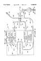
- FIG. 1illustrates in a schematic view a patient ventilation apparatus including an endotracheal breathing tube having a distally mounted pressure sensor in accordance with the present invention
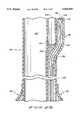
- FIG. 2Aillustrates in cross section in a partial plan view the portion of the endotracheal breathing tube depicted in FIG. 1 below the balloon cuff;
- FIG. 2Billustrates in cross section in a partial plan view a portion of the endotracheal breathing tube depicted in FIG. 1 above the balloon cuff and shows the optical pathways exiting the endotracheal breathing tube;
- FIG. 3shows the endotracheal breathing tube shown in FIGS. 1, 2A and 2B in a cross sectional view taken along cutting plane 3--3 of FIG. 2A;
- FIG. 4illustrates alternative locations for an endotracheal breathing tube pressure transducer in accordance with the present invention
- FIG. 5illustrates an alternative embodiment of an endotracheal breathing tube in accordance with the present invention and shows the groove running the length of the breathing tube;
- FIG. 6shows a cross sectional view taken along cutting plane 6--6 of FIG. 5 and shows the pressure transducer and light conducting fibers are disposed within the groove running along the exterior surface of the breathing tube.
- FIG. 1shows in a schematic view a ventilator 10 and attached airway and breathing tubes useful in accordance with the present invention.
- Ventilator 10is attached to an airway tube 12 having a pair of branches 14 and 16.
- Branch 14is attached at its proximal end 18 to ventilator 10
- branch 16is attached at its proximal end 20 to ventilator 10.
- Branches 14 and 16are connected to a T-coupling 22 at their distal ends 24 and 25, respectively.
- Branch 14is used to supply a ventilation gas to the patient as indicated by arrow 26, while branch 16 is used for the removal of exhalation therapy gases from the patient as indicated by arrow 27.
- Coupling 22is connected at its other end to the proximal end 28 of endotracheal breathing tube 30.
- endotracheal breathing tube 30may, but need not, include a balloon cuff 32 located near the distal end 34 of breathing tube 30.
- Breathing tube 30may have beveled end 36 as best seen in FIG. 4.
- ventilator 10On the inhalation side, ventilator 10 is usually connected to an oxygen supply 40 by a gas line 42 and to an air supply 44 by a gas line 46.
- Ventilator 10includes a gas mixing valve 48 that receives air from air supply 44 via passage 46 and oxygen from oxygen supply 40 via passage 42 and mixes them in the appropriate preselected ventilation therapy ratios.
- medicationmay also be included in the ventilation therapy gas supplied to the patient, though the means for doing so will not be discussed herein as it is well known in the art.
- This mixturewhich comprises the ventilation therapy gas inhaled by the patient, is supplied by means of a line 50 to a pressure valve 52.
- Pressure valve 52controls any mixing of the oxygen and the air and the pressure of the ventilation therapy gas supplied to the patient through branch 14.
- Pressure valve 52is connected by a line 54 to a flow control valve 56.
- Flow control valve 56controls the volume of gas being supplied to branch 14 of airway tube 12.
- Airway tube 12is in turn connected by known means to flow control valve 56.
- exhaust branch 16is connected by known means to a resistance valve 60, which measures the patient's peak expiratory end pressure (P.E.E.P.) and which in turn is connected via a line 62 to the appropriate exhaust filters and condensers 64 used to cleanse and filter the exhalation gases before it is released back into the atmosphere.
- P.E.E.P.peak expiratory end pressure
- Ventilator 10further includes a control and calculation unit 65.
- Unit 65comprises microprocessor 66 that controls the operation of gas mixing valve 48 over line 68, pressure valve 52 over line 70, flow control valve 56 over line 72, and resistance valve 60 over line 74.
- Microprocessor 66through the appropriate programming controls the operation of valves 48, 52, 56 and 60 based upon pressure sensed by a pressure transducer to be described below. Actual valve operation is accomplished by well known means such as a solenoid and will not be described further.
- a signalis transmitted to control and calculation unit 65 via an interior fiber optic cable 78.
- Control and calculation unit 65further includes a light source, such as a light or laser emitting diode, that is used to provide the light signal transmitted via optical cables 78 and 80.
- Optical cable 80enters endotracheal tube 30 and travels through a passage therein to a pressure sensor at the distal end 34 of breathing tube 30.
- optical cable 80may either exit breathing tube 30 at a location between the balloon cuff and the proximal end 28 as indicated by reference numeral 82, or as shown in phantom by reference numeral 84, may enter the endotracheal breathing tube 30 at its proximal end connection 28 to T-coupling 22.
- a cuff inflation tube 88that extends, as is well known in the art, from the proximal end 28 of breathing tube 30 to balloon cuff 32.
- Cuff inflation tube 88in turn has appropriate couplings 90 disposed at the end thereof for attachment to an appropriate air supply to inflate cuff 32.
- Ventilator 10functions as a pressure compensation to control the volume and pressure of the ventilation therapy gas provided to the patient.
- Control and calculation unit 65provides a light signal to a pressure transducer and receives a return light signal therefrom.
- Control and calculation unit 65compares the intensity of the transmitted and returned signal and calculates the gas pressure sensed by the pressure transducer.
- Microprocessor 66then sends the appropriate signals to valves 40, 52 and 60 based upon an appropriate algorithm so as to properly control the operation of the valves and so as to properly and timely ventilate the patient.
- Ventilator 10as is well known, will usually include a signal display and the appropriate controls.
- FIG. 2Bis a partial cross sectional view of the endotracheal tube 30 showing the entrance/exit of optical cable or lumen 80 from the endotracheal tube 30 and also shows in partial view the balloon cuff 32.
- Endotracheal tube 30includes a plurality of passages, here two as indicated by reference numerals 100 and 102, that are preferably non-communicating except as hereafter described.
- First passage 100serves as the flow path for the ventilation therapy gases provided to the patient and as the flow path for the exhalation or expiration of breath from the lungs of the patient.
- Second passage 102serves as the passage for the appropriate positioning of a pressure transducer 104.
- second passage 102is formed entirely within a thickened wall portion of breathing tube 30 and is substantially fully enclosed the entire length of breathing tube 30.
- the space in passage 102is typically maintained at ambient atmospheric pressure during measurements by being in communication with the atmosphere at the proximal end of cable 78 inside control and calculation unit 65. This is important in measuring pressures as will be described below in further detail.
- First and second passages 100 and 102each have a substantially tubular configuration and are separated by a wall 105.
- the pressure transducer 104is preferably of the fiber optic type. This type of pressure sensor will be described below; however, a pressure sensor such as known solid state types of devices that also respond nearly instantaneously could also be used in accordance with the present invention.
- the fiber optic type of pressure transducerconverts sensed pressure variations into a light modulated signal. The device is calibrated so that the light signal is proportional to pressure.
- An optical pathwayis the preferred mode of light transmission from a light source usually disposed within ventilator 10 to the pressure sensor and back to ventilator 10. This optical pathway is usually provided by optical fibers or leads.
- Such leadsmay be in the configuration of a single fiber which serves to both send and receive light signals to and from the transducer, in the form of two fiber optic leads where one fiber serves to transmit and one to receive light signals, or in the form of a fiber bundle.
- the dual lead configurationis preferred and is disclosed herein, reference numerals 106 and 108 indicating a pair of elongated, parallel fiber optic leads which extend longitudinally within second tubular passage 102.
- the proximal ends of fiber optic leads 106 and 108terminate within a connector (not shown) at ventilator 10, and their distal ends 110 and 112, respectively, terminate within a pressure transducer assembly 114.
- Passage 102thus serves as a passage for the transmission of pressure indicating signals from pressure transducer assembly 114 (FIG.
- the connector at ventilator 10serves to connect the transducer leads 106 and 108 to lead 78, which in turn is connected to control and calculation unit 65 and, hence, to microprocessor 66, which, as noted, provides an output signal to a display on ventilator 10.
- Fiber optic lead 106serves as a light signal transmitting path for transmitting light from the light source at control unit 65 to the pressure transducer assembly 114.
- Fiber optic lead 108serves to convey light signals from the pressure transducer assembly 114 back to the control unit 65.
- the transducer assembly 114includes a housing 120 which is wholly contained within second passage 102 near the distal end thereof.
- Housing 120may be made from metal or plastic.
- Housing 120is preferably made of stainless steel.
- biocompatible, rigid plasticsuch as polycarbonate, acrylic, or polyurethane, could be used.
- Housing 120is shown most clearly in the side elevation cross section view of FIG. 2A and the end elevation cross section view of FIG. 3. It is preferably of a hollow cylindrical shape, and has opposed proximal and distal ends 122 and 124, respectively.
- Housing 120receives the distal ends 110 and 112 of fiber optic leads 106 and 108 in the manner shown in FIGS. 2A and 3.
- the end of housing 120 adjacent to distal end 124is hollow or open as shown in FIGS.
- a reflector 128is utilized.
- Reflector 128comprises a reflective surface which may be integral to, formed on or applied to the proximal end 129 of an end plug 130.
- reflector 128has a substantially planar or flat surface.
- end plug 130may be formed so as to provide a concave recess on its inner end which forms a segment of a sphere, which serves as reflector 128.
- End plug 130has a substantially cylindrical configuration and is received within the cavity 126 at the distal end 124 of housing 120 and retained therein by known means.
- End plug 130may be made out of metal or plastic. If end plug 130 is made out of plastic, preferably relatively hard reflector surface 128 may comprise a metal surface electroplated thereon, or a hot stamped, reflective coating applied to the proximal end of end plug 130. If end plug 130 is made of metal, such as titanium or stainless steel, reflector surface 128 may comprise a polished surface on the proximal end of plug 130 or reflector 128 may comprise a reflective material, such as gold, which has a higher degree of reflectance relative to the frequency of transmitted visible red light, plated to the distal end of end plug 130. As also appears most clearly in FIG. 2A, housing 120 is molded or cut out to the configuration shown so as to provide an aperture 132 along that side of housing 120 adjacent first passage 100.
- opening 134is made in the wall 105 adjacent to aperture 132. As shown in the drawings, opening 134 has a configuration conforming in configuration but of larger extent than the outer perimeter of the aperture 132 formed in housing 120. Such a configuration is not required by the present invention. For example, it may be advantageous to make opening 134 such that it has a smaller size than that of aperture 132. Furthermore, in some embodiments it may be desirable to cover opening 134 with a screen or gel of some type. Opening 134 in the wall 105 serves as an aperture or port for pressure sensing and is preferably the only means of communication between passages 100 and 102.
- a flexible membrane 136is positioned on the housing 120.
- Flexible membrane 136is disposed in covering relation to the aperture 132, adjacent to the wall opening 134.
- the portion of flexible membrane 136 which overlies the aperture 132 in the housing 120is a pressure-sensitive segment 138 which is free to flex or deflect transversely with respect to the path of light passing longitudinally between fiber optic lead distal ends 110 and 112 via reflector 128.
- Membrane 136may take the form of a patch or, as shown, a sleeve.
- membrane 136is in the form of a cylindrical sleeve embracing the housing 120 in a snug fit therewith.
- the material of the membrane sleeveis preferably elastomeric, and could be urethane or silicone.
- flexible membrane 136is secured around the outside of housing 120 over the aperture 132 cut therein so as to be placed in tension in a prestressed condition.
- membrane sleeve 136 prior to installation over housing 120has an inner diameter less than the preferred outside diameter of housing 120.
- Membrane sleeve 136is stretched so as to get it over housing 120.
- a silicone membrane sleeve 136may be placed in a solution which causes it to dilate, after which it is slipped over the end of the housing 120 in covering relation to the aperture 132. The membrane sleeve then returns to its undilated state as the solution evaporates. Freon has been found to be satisfactory for use as a dilating solution.
- the membrane sleeve 136is prestressed in tension around housing 120 and over the aperture 132. This causes the membrane to be initially set at an inwardly flexed condition in which pressure responsive segment 138 thereof is curved inwardly. As shown in FIG. 2A, pressure responsive segment 138 assumes somewhat the shape of a segment of a sphere in its inwardly curved set position. The membrane sleeve is placed in tension a predetermined extent so that segment 138 will have an inward, sufficient deflection that segment 138 will extend slightly into the linear path of light traveling between distal ends 110 and 112 of fiber optic leads 106 and 108, respectively, via reflector 128. Segment 138 is free to flex either inwardly or outwardly.
- membrane segment 138in response to changes in the pressure differential across its inner and outer surfaces is assured by connecting the underside or inner face of membrane segment 138 to an atmospheric or other reference pressure. That is, second passage 102 is at atmospheric or a known reference pressure.
- reflector 128is spaced apart from distal ends 110 and 112 of the two fiber optic paths, in opposing relation thereto.
- light signals conducted by fiber optic lead 106are directed from distal end 110 onto the surface of reflector 128, and are reflected back thereby to distal end 112 of fiber optic return path 108.
- Arrows 139a and 139b within fiber optic leads 106 and 108indicate such light transmission to and from reflector 128, respectively.
- the length of the gap 140 between fiber optic distal ends 110 and 112 and the surface of reflector 128is predetermined so as to optimize light signal transmission. The operation of the pressure transducer is believed to be clearly understood from the foregoing description.
- the outer surface 141 of pressure-responsive segment 138 of membrane 136 exterior of housing 120is exposed to pressure within the body of a patient, that is, in the patient's trachea.
- the inner surface 142 of membrane segment 138is exposed to pressure inside of housing 120, which will normally be atmospheric pressure, though as noted, a standard reference pressure may be used.
- 3 s body as sensed on the outside surface 141 of pressure responsive segment 138 of membrane 136will cause segment 138 to deflect inwardly into the gap 140 provided between distal or terminal ends 110 and 112 of fiber optic leads 106 and 108 and the reflector 128.
- Housing 120is held in place at both ends by suitable potting or cementing material 144 as is well known in the art.
- This potting or cementing material 144also serves to isolate the atmospheric pressure inside passage 102 from the outside pressure on surface 141 of segment 138 of membrane 136.
- potting 146is used to seal off second passage 102 where optical cable 80 exits second passage 102.
- second passage 102 and therefore endotracheal tube 30includes an opening 148 therein wherein optical cable 80 exits and enters second passage 102.
- optical cable 80includes an outer cover or sheath 150 that circumscribes optical fibers 106 and 108. If desired, cover 150 may terminate after insertion of the optical cable 80 within second passage 102 of endotracheal tube 30. Cover 150 may continue distally to the transducer assembly 114 as seen in FIGS. 5 and 6.
- FIG. 4alternative locations of an endotracheal tube pressure transducer are shown. With respect to each of the locations to be discussed below, it should be noted that each location is shown along a single side of the endotracheal breathing tube 30.
- the particular circumferential position of the pressure transduceris not critical, however.
- the transducercan be located at any circumferential position relative to endotracheal breathing tube 30 and be within the scope of the present invention.
- location 160 for pressure transducer assembly 114is substantially that location shown in FIGS. 2A and 3.
- a pressure transducer assembly 114 similar to that shown in FIGS. 2A and 3could also be located at position 162.
- first and second passages 100 and 102could be completely non-communicating.
- an openingwould be made in the outer surface 164 of endotracheal tube 30.
- the pressure differential sensedwould be between that of the atmospheric or reference pressure on the inner surface 142 of the pressure sensitive segment 138 of membrane 136 and the pressure on the outer surface 164 of endotracheal tube 30.
- a third alternative location for the pressure transducer assembly 114would be at position 166 which, as shown, is on the proximal side of the balloon cuff 32. In all other respects, the pressure transducer 104 and transducer assembly 114 would be substantially similar to that at preferred location 160. Finally, a fourth location for a transducer assembly 114 would be as shown at 168 which is substantially adjacent the proximal end 28 of endotracheal tube 30.
- the pressure transducer assemblyis to be located proximally of balloon cuff 32 that its location must always be such that the pressure being sensed is that in the first passage 100. That is, because balloon cuff 32 will substantially close off the trachea, if the pressure assembly 114 were located at locations 166 or 168, it would sense the pressure on the outside surface 164 of endotracheal tube 30, as does the transducer assembly at location 162. Thus, a false pressure reading would be given since the portion of the endotracheal tube 30 distally displaced from balloon cuff 32 is pressure un-coupled from the portion of endotracheal tube 30 proximally placed of balloon cuff 32. Where the transducer assembly is disposed distally of the balloon cuff 32, it may be placed such that the pressure being sensed is either internal of first passage 100 or external on surface 164 of endotracheal tube 30.
- FIGS. 5 and 6show an alternative embodiment of the present invention wherein optical cable 80 is disposed within a second passage taking the form of a groove 170 formed in the outer surface 164 of an endotracheal tube 171.
- Groove 170has a substantially circular configuration to conform to the outer surface 172 (FIG. 2B) of optical cable 80, whose sheath 150 will be carried substantially to pressure transducer assembly 114 rather than terminate as shown in FIG. 2B.
- Groove 170may, as shown, be substantially open to the outer environment or it may, if desired, be only partially opened thereto.
- groove 170has an opening 174 that is narrower than its diameter so as to form a pair of flexible flaps 176 that may be spread apart to insert the optical cable 80 and that then return to their normal configuration tightly holding the optical cable 80 and pressure transducer assembly 114 in place.
- pressure transducer assembly 114will be rotated 180° from the position shown in FIG. 2A such that the pressure sensitive member is exposed to the pressure on the outside of the breathing tube 30.
- the endotracheal breathing tubemay be trimmed to the desired length and the optical cable 80 with the attached fiber optic pressure transducer assembly 114 may be inserted into groove 170.
- Groove 170may also be formed in the embodiment of breathing tube 30 shown in FIGS. 2-4 and used as a channel for disposing other sensors, such as temperature or gas measurement sensors.
- the endotracheal breathing tube shown in FIGS. 5 and 6is shown without a balloon cuff.
- endotracheal tubes intended for use by adultsusually have such cuffs while those intended for use children, including infants, may not have them.
- the present inventionis useful with cuffed and uncuffed as well as trimmable and untrimmable types of endotracheal breathing tubes.
Landscapes
- Health & Medical Sciences (AREA)
- Pulmonology (AREA)
- Emergency Medicine (AREA)
- Engineering & Computer Science (AREA)
- Anesthesiology (AREA)
- Biomedical Technology (AREA)
- Heart & Thoracic Surgery (AREA)
- Hematology (AREA)
- Life Sciences & Earth Sciences (AREA)
- Animal Behavior & Ethology (AREA)
- General Health & Medical Sciences (AREA)
- Public Health (AREA)
- Veterinary Medicine (AREA)
- Measurement Of The Respiration, Hearing Ability, Form, And Blood Characteristics Of Living Organisms (AREA)
Abstract
Description
Claims (17)
Priority Applications (1)
| Application Number | Priority Date | Filing Date | Title |
|---|---|---|---|
| US08/028,355US5546935A (en) | 1993-03-09 | 1993-03-09 | Endotracheal tube mounted pressure transducer |
Applications Claiming Priority (1)
| Application Number | Priority Date | Filing Date | Title |
|---|---|---|---|
| US08/028,355US5546935A (en) | 1993-03-09 | 1993-03-09 | Endotracheal tube mounted pressure transducer |
Publications (1)
| Publication Number | Publication Date |
|---|---|
| US5546935Atrue US5546935A (en) | 1996-08-20 |
Family
ID=21842991
Family Applications (1)
| Application Number | Title | Priority Date | Filing Date |
|---|---|---|---|
| US08/028,355Expired - LifetimeUS5546935A (en) | 1993-03-09 | 1993-03-09 | Endotracheal tube mounted pressure transducer |
Country Status (1)
| Country | Link |
|---|---|
| US (1) | US5546935A (en) |
Cited By (119)
| Publication number | Priority date | Publication date | Assignee | Title |
|---|---|---|---|---|
| US5735267A (en)* | 1996-03-29 | 1998-04-07 | Ohmeda Inc. | Adaptive control system for a medical ventilator |
| US5740796A (en)* | 1995-12-01 | 1998-04-21 | Siemens Elema Ab | Ventilator system and method for operating same |
| US5752921A (en)* | 1996-01-11 | 1998-05-19 | Korr Medical Technologies, Inc. | Method and apparatus for determining tracheal pressure |
| US5887611A (en)* | 1996-12-31 | 1999-03-30 | The University Of Florida | Gas blender |
| WO1999020332A1 (en)* | 1997-10-20 | 1999-04-29 | Christopher Kent L | System for monitoring and treating sleep disorders using a transtracheal catheter |
| US5906204A (en)* | 1996-12-19 | 1999-05-25 | Respiratory Support Products, Inc. | Endotracheal pressure monitoring and medication system |
| FR2778547A1 (en) | 1998-05-18 | 1999-11-19 | Commissariat Energie Atomique | Probe or catheter measuring physical parameters of e.g. bodily fluid- or gas- flow and pressure, for medical applications |
| US6021781A (en)* | 1998-03-18 | 2000-02-08 | Medworks Corporation | Intraurethral pressure monitoring assembly and method of treating incontinence using same |
| US6142150A (en)* | 1998-03-24 | 2000-11-07 | Nellcor Puritan-Bennett | Compliance compensation in volume control ventilator |
| US6152132A (en)* | 1997-09-11 | 2000-11-28 | Siemens Elema Ab | Inspiratory tube for a ventilator |
| WO2001030431A1 (en)* | 1999-10-27 | 2001-05-03 | Glukomeditech Ag | Tubus comprising a device for dynamically detecting the endotracheal pressure |
| US6279574B1 (en)* | 1998-12-04 | 2001-08-28 | Bunnell, Incorporated | Variable flow and pressure ventilation system |
| US6390091B1 (en) | 1999-02-03 | 2002-05-21 | University Of Florida | Method and apparatus for controlling a medical ventilator |
| US6450164B1 (en) | 2000-08-17 | 2002-09-17 | Michael J. Banner | Endotracheal tube pressure monitoring system and method of controlling same |
| US6457472B1 (en)* | 1996-12-12 | 2002-10-01 | The Johns Hopkins University | Method and apparatus for providing ventilatory support to a patient |
| US20030010339A1 (en)* | 1999-02-03 | 2003-01-16 | University Of Florida | Method and apparatus for nullifying the imposed work of breathing |
| US6571796B2 (en) | 2001-02-08 | 2003-06-03 | University Of Florida | Tracheal pressure ventilation respiratory system |
| US20030101998A1 (en)* | 1997-12-24 | 2003-06-05 | Laryngeal Mask Company (Uk) Limited | Monitoring and control for a laryngeal mask airway device |
| US20030172925A1 (en)* | 1997-12-24 | 2003-09-18 | Mario Zocca | Monitoring and control for a laryngeal mask airway device |
| US20040003813A1 (en)* | 1999-06-30 | 2004-01-08 | Banner Michael J. | Medical ventilator and method of controlling same |
| US20040003814A1 (en)* | 2000-08-17 | 2004-01-08 | Banner Michael J. | Endotracheal tube pressure monitoring system and method of controlling same |
| US20050274383A1 (en)* | 1998-10-06 | 2005-12-15 | Brain Archibald I | Laryngeal mask airway device |
| US20070000494A1 (en)* | 1999-06-30 | 2007-01-04 | Banner Michael J | Ventilator monitor system and method of using same |
| USRE39938E1 (en) | 1996-03-01 | 2007-12-18 | Indian Ocean Medical, Inc. | Gastro-laryngeal mask |
| US20070299357A1 (en)* | 2006-06-09 | 2007-12-27 | Diana Villegas | Bronchial or tracheal tissular water content sensor and system |
| US20080072905A1 (en)* | 2006-09-25 | 2008-03-27 | Baker Clark R | Carbon dioxide-sensing airway products and technique for using the same |
| US20080078388A1 (en)* | 2006-09-29 | 2008-04-03 | Nellcor Puritan Bennett Incorporated | Patient interface having an integrated system for communicating data to a ventilator |
| US20080078387A1 (en)* | 2006-09-29 | 2008-04-03 | Nellcor Puritan Bennett Incorporated | Breathing Assistance System Having Integrated Electrical Conductors for Communicating Data |
| US20080091117A1 (en)* | 2006-10-16 | 2008-04-17 | Choncholas Gary J | Method and apparatus for airway compensation control |
| US20080142003A1 (en)* | 2006-12-13 | 2008-06-19 | Arcadia Medical Corporation | MRI Compatible Airway Management Device |
| US20080230062A1 (en)* | 2007-03-23 | 2008-09-25 | General Electric Company | Setting expiratory time in mandatory mechanical ventilation based on a deviation from a stable condition of exhaled gas volumes |
| US7487778B2 (en) | 2003-08-11 | 2009-02-10 | Breathe Technologies, Inc. | Tracheal catheter and prosthesis and method of respiratory support of a patient |
| US20090107503A1 (en)* | 1994-06-17 | 2009-04-30 | Trudell Medical Limited | Nebulizing catheter system and methods of use and manufacture |
| US20090120439A1 (en)* | 2007-11-08 | 2009-05-14 | Fred Goebel | Method of triggering a ventilator |
| US7533670B1 (en) | 2005-09-20 | 2009-05-19 | Breathe Technologies, Inc. | Systems, methods and apparatus for respiratory support of a patient |
| US20090133701A1 (en)* | 2005-05-27 | 2009-05-28 | The Laryngeal Mask Company Ltd. | Laryngeal mask airway device |
| US7588033B2 (en) | 2003-06-18 | 2009-09-15 | Breathe Technologies, Inc. | Methods, systems and devices for improving ventilation in a lung area |
| US20090241964A1 (en)* | 2007-03-12 | 2009-10-01 | Pulmonx, Inc. | Methods and devices for passive residual lung volume reduction and functional lung volume expansion |
| US7631642B2 (en) | 2006-05-18 | 2009-12-15 | Breathe Technologies, Inc. | Tracheostoma spacer, tracheotomy method, and device for inserting a tracheostoma spacer |
| US20100078030A1 (en)* | 2008-09-29 | 2010-04-01 | Nellcor Puritan Bennett Llc | Airway system with carbon dioxide sensor for determining tracheal cuff inflation and technique for using the same |
| US20100288283A1 (en)* | 2009-05-15 | 2010-11-18 | Nellcor Puritan Bennett Llc | Dynamic adjustment of tube compensation factor based on internal changes in breathing tube |
| US20100312132A1 (en)* | 2009-06-03 | 2010-12-09 | Nellcor Puritan Bennett Llc | Trachea pressure determination method and device |
| US20100319702A1 (en)* | 2009-06-17 | 2010-12-23 | Nellcor Puritan Bennett Llc | Method and system for determining tracheal and location information for a tracheal tube |
| US20100319703A1 (en)* | 2009-06-18 | 2010-12-23 | Nellcor Puritan Bennett Llc | Tracheal tube with lumen for tracheal pressure measurement and technique for using the same |
| US20100326446A1 (en)* | 2009-06-30 | 2010-12-30 | Nellcor Puritan Bennett Llc | Tracheal tube with lumen for tracheal pressure measurement and technique for using the same |
| US20110144514A1 (en)* | 2009-12-16 | 2011-06-16 | Nellcor Puritan Bennett Llc | Tracheal Tube with Pressure Monitoring Lumen and Method for Using the Same |
| US20110152678A1 (en)* | 2005-01-20 | 2011-06-23 | Pulmonx Corporation | Methods and devices for passive residual lung volume reduction and functional lung volume expansion |
| US20110178419A1 (en)* | 2010-01-18 | 2011-07-21 | Nellcor Puritan Bennett Llc | Tracheal tube with pressure monitoring lumen and method for using the same |
| USD653749S1 (en) | 2010-04-27 | 2012-02-07 | Nellcor Puritan Bennett Llc | Exhalation module filter body |
| USD655405S1 (en) | 2010-04-27 | 2012-03-06 | Nellcor Puritan Bennett Llc | Filter and valve body for an exhalation module |
| USD655809S1 (en) | 2010-04-27 | 2012-03-13 | Nellcor Puritan Bennett Llc | Valve body with integral flow meter for an exhalation module |
| US8136527B2 (en) | 2003-08-18 | 2012-03-20 | Breathe Technologies, Inc. | Method and device for non-invasive ventilation with nasal interface |
| US8381729B2 (en) | 2003-06-18 | 2013-02-26 | Breathe Technologies, Inc. | Methods and devices for minimally invasive respiratory support |
| US8434479B2 (en) | 2009-02-27 | 2013-05-07 | Covidien Lp | Flow rate compensation for transient thermal response of hot-wire anemometers |
| US8439036B2 (en) | 2009-12-01 | 2013-05-14 | Covidien Lp | Exhalation valve assembly with integral flow sensor |
| US8439037B2 (en) | 2009-12-01 | 2013-05-14 | Covidien Lp | Exhalation valve assembly with integrated filter and flow sensor |
| US8457706B2 (en) | 2008-05-16 | 2013-06-04 | Covidien Lp | Estimation of a physiological parameter using a neural network |
| US8469031B2 (en) | 2009-12-01 | 2013-06-25 | Covidien Lp | Exhalation valve assembly with integrated filter |
| US8469030B2 (en) | 2009-12-01 | 2013-06-25 | Covidien Lp | Exhalation valve assembly with selectable contagious/non-contagious latch |
| US8567399B2 (en) | 2007-09-26 | 2013-10-29 | Breathe Technologies, Inc. | Methods and devices for providing inspiratory and expiratory flow relief during ventilation therapy |
| USD692556S1 (en) | 2013-03-08 | 2013-10-29 | Covidien Lp | Expiratory filter body of an exhalation module |
| USD693001S1 (en) | 2013-03-08 | 2013-11-05 | Covidien Lp | Neonate expiratory filter assembly of an exhalation module |
| US8677999B2 (en) | 2008-08-22 | 2014-03-25 | Breathe Technologies, Inc. | Methods and devices for providing mechanical ventilation with an open airway interface |
| USD701601S1 (en) | 2013-03-08 | 2014-03-25 | Covidien Lp | Condensate vial of an exhalation module |
| US8770193B2 (en) | 2008-04-18 | 2014-07-08 | Breathe Technologies, Inc. | Methods and devices for sensing respiration and controlling ventilator functions |
| US8776793B2 (en) | 2008-04-18 | 2014-07-15 | Breathe Technologies, Inc. | Methods and devices for sensing respiration and controlling ventilator functions |
| US8800557B2 (en) | 2003-07-29 | 2014-08-12 | Covidien Lp | System and process for supplying respiratory gas under pressure or volumetrically |
| US20140288456A1 (en)* | 2007-05-18 | 2014-09-25 | Breathe Technologies, Inc. | Methods and devices for sensing respiration and providing ventilation therapy |
| US8925545B2 (en) | 2004-02-04 | 2015-01-06 | Breathe Technologies, Inc. | Methods and devices for treating sleep apnea |
| US8939152B2 (en) | 2010-09-30 | 2015-01-27 | Breathe Technologies, Inc. | Methods, systems and devices for humidifying a respiratory tract |
| USD731049S1 (en) | 2013-03-05 | 2015-06-02 | Covidien Lp | EVQ housing of an exhalation module |
| USD731048S1 (en) | 2013-03-08 | 2015-06-02 | Covidien Lp | EVQ diaphragm of an exhalation module |
| USD731065S1 (en) | 2013-03-08 | 2015-06-02 | Covidien Lp | EVQ pressure sensor filter of an exhalation module |
| USD736905S1 (en) | 2013-03-08 | 2015-08-18 | Covidien Lp | Exhalation module EVQ housing |
| US9132250B2 (en) | 2009-09-03 | 2015-09-15 | Breathe Technologies, Inc. | Methods, systems and devices for non-invasive ventilation including a non-sealing ventilation interface with an entrainment port and/or pressure feature |
| US9144658B2 (en) | 2012-04-30 | 2015-09-29 | Covidien Lp | Minimizing imposed expiratory resistance of mechanical ventilator by optimizing exhalation valve control |
| US9180270B2 (en) | 2009-04-02 | 2015-11-10 | Breathe Technologies, Inc. | Methods, systems and devices for non-invasive open ventilation with gas delivery nozzles within an outer tube |
| USD744095S1 (en) | 2013-03-08 | 2015-11-24 | Covidien Lp | Exhalation module EVQ internal flow sensor |
| US20160030699A1 (en)* | 2013-03-15 | 2016-02-04 | The General Hospital Corporation | Synthesis of nitric oxide gas for inhalation |
| US20160038710A1 (en)* | 2013-03-15 | 2016-02-11 | The General Hospital Corporation | Inspiratory synthesis of nitric oxide |
| US9265904B2 (en) | 2009-07-06 | 2016-02-23 | Teleflex Life Sciences | Artificial airway |
| US9327089B2 (en) | 2012-03-30 | 2016-05-03 | Covidien Lp | Methods and systems for compensation of tubing related loss effects |
| WO2016083782A1 (en)* | 2014-11-25 | 2016-06-02 | Nottingham University Hospitals Nhs Trust | Airway maintenance device |
| US9364624B2 (en) | 2011-12-07 | 2016-06-14 | Covidien Lp | Methods and systems for adaptive base flow |
| US9498589B2 (en) | 2011-12-31 | 2016-11-22 | Covidien Lp | Methods and systems for adaptive base flow and leak compensation |
| US9528897B2 (en) | 2009-08-13 | 2016-12-27 | Chimden Medical Pty Ltd | Pressure indicator |
| USD775345S1 (en) | 2015-04-10 | 2016-12-27 | Covidien Lp | Ventilator console |
| US9629971B2 (en) | 2011-04-29 | 2017-04-25 | Covidien Lp | Methods and systems for exhalation control and trajectory optimization |
| US9649458B2 (en) | 2008-09-30 | 2017-05-16 | Covidien Lp | Breathing assistance system with multiple pressure sensors |
| US9675772B2 (en) | 2010-10-15 | 2017-06-13 | The Laryngeal Mask Company Limited | Artificial airway device |
| WO2017190157A1 (en)* | 2016-04-27 | 2017-11-02 | Suspended Animation, Inc. | Apparatus and method for delivering fluids and/or gases to the lungs |
| US9950135B2 (en) | 2013-03-15 | 2018-04-24 | Covidien Lp | Maintaining an exhalation valve sensor assembly |
| US9962512B2 (en) | 2009-04-02 | 2018-05-08 | Breathe Technologies, Inc. | Methods, systems and devices for non-invasive ventilation including a non-sealing ventilation interface with a free space nozzle feature |
| US9974912B2 (en) | 2010-10-01 | 2018-05-22 | Teleflex Life Sciences Unlimited Company | Artificial airway device |
| CN108404270A (en)* | 2018-05-18 | 2018-08-17 | 高鸿 | A kind of cuff for endotracheal catheter pressure monitoring and control system and control method |
| US10099028B2 (en) | 2010-08-16 | 2018-10-16 | Breathe Technologies, Inc. | Methods, systems and devices using LOX to provide ventilatory support |
| US10239038B2 (en) | 2017-03-31 | 2019-03-26 | The General Hospital Corporation | Systems and methods for a cooled nitric oxide generator |
| US10252020B2 (en) | 2008-10-01 | 2019-04-09 | Breathe Technologies, Inc. | Ventilator with biofeedback monitoring and control for improving patient activity and health |
| US10286176B2 (en) | 2017-02-27 | 2019-05-14 | Third Pole, Inc. | Systems and methods for generating nitric oxide |
| US10328228B2 (en) | 2017-02-27 | 2019-06-25 | Third Pole, Inc. | Systems and methods for ambulatory generation of nitric oxide |
| US10549054B2 (en) | 2011-02-02 | 2020-02-04 | Teleflex Life Sciences Unlimited Company | Artificial airway |
| US10576229B2 (en) | 2009-03-03 | 2020-03-03 | The Laryngeal Mask Company Limited | Artificial airway device |
| US10792449B2 (en) | 2017-10-03 | 2020-10-06 | Breathe Technologies, Inc. | Patient interface with integrated jet pump |
| US10806327B2 (en) | 2011-11-30 | 2020-10-20 | Teleflex Life Sciences Pte, Ltd. | Laryngeal mask for use with an endoscope |
| US11045620B2 (en) | 2019-05-15 | 2021-06-29 | Third Pole, Inc. | Electrodes for nitric oxide generation |
| SE2150055A1 (en)* | 2020-01-23 | 2021-07-24 | Monivent Ab | A device for a respiration arrangement |
| US11154672B2 (en) | 2009-09-03 | 2021-10-26 | Breathe Technologies, Inc. | Methods, systems and devices for non-invasive ventilation including a non-sealing ventilation interface with an entrainment port and/or pressure feature |
| US11291792B2 (en)* | 2019-07-24 | 2022-04-05 | Bunnell, Incorporated | Pulmonary ventilator with changeable filters |
| CN114432559A (en)* | 2022-02-08 | 2022-05-06 | 无锡圣诺亚科技有限公司 | A ventilating conduit and connecting device with stable pressure difference |
| US11479464B2 (en) | 2019-05-15 | 2022-10-25 | Third Pole, Inc. | Systems and methods for generating nitric oxide |
| US11497878B2 (en) | 2014-10-20 | 2022-11-15 | The General Hospital Corporation | Systems and methods for synthesis of nitric oxide |
| US11617850B2 (en) | 2016-03-25 | 2023-04-04 | The General Hospital Corporation | Delivery systems and methods for electric plasma synthesis of nitric oxide |
| US11691879B2 (en) | 2020-01-11 | 2023-07-04 | Third Pole, Inc. | Systems and methods for nitric oxide generation with humidity control |
| US11827989B2 (en) | 2020-06-18 | 2023-11-28 | Third Pole, Inc. | Systems and methods for preventing and treating infections with nitric oxide |
| US11833309B2 (en) | 2017-02-27 | 2023-12-05 | Third Pole, Inc. | Systems and methods for generating nitric oxide |
| US11883029B2 (en) | 2005-01-20 | 2024-01-30 | Pulmonx Corporation | Methods and devices for passive residual lung volume reduction and functional lung volume expansion |
| US11896767B2 (en) | 2020-03-20 | 2024-02-13 | Covidien Lp | Model-driven system integration in medical ventilators |
| US11975139B2 (en) | 2021-09-23 | 2024-05-07 | Third Pole, Inc. | Systems and methods for delivering nitric oxide |
| US12420039B2 (en) | 2020-01-23 | 2025-09-23 | Monivent Ab | Device for a respiration arrangement |
Citations (32)
| Publication number | Priority date | Publication date | Assignee | Title |
|---|---|---|---|---|
| US3788326A (en)* | 1970-07-29 | 1974-01-29 | H Jacobs | Distally perforated catheter for use in ventilating system |
| US3893451A (en)* | 1972-10-11 | 1975-07-08 | Herve Durand | Pressure transmission device |
| US4141356A (en)* | 1976-06-16 | 1979-02-27 | Bourns, Inc. | Respirator system and method |
| US4155356A (en)* | 1976-02-10 | 1979-05-22 | Venegas Jose G | Respiration assisting apparatus and method |
| US4214593A (en)* | 1978-09-18 | 1980-07-29 | Mallinckrodt, Inc. | Esophageal pressure monitoring device |
| US4252131A (en)* | 1978-04-17 | 1981-02-24 | American Home Products Corporation | Catheter for measuring intrauterine pressure |
| US4346584A (en)* | 1980-10-20 | 1982-08-31 | Boehringer John R | Gas analyzer |
| US4387711A (en)* | 1981-01-27 | 1983-06-14 | Mallinckrodt, Inc. | Medical device with inflatable cuff |
| US4484585A (en)* | 1981-09-12 | 1984-11-27 | Richard Wolf Gmbh | Catheters |
| US4487206A (en)* | 1982-10-13 | 1984-12-11 | Honeywell Inc. | Fiber optic pressure sensor with temperature compensation and reference |
| US4502490A (en)* | 1980-10-28 | 1985-03-05 | Antec Systems Limited | Patient monitoring equipment, probe for use therewith, and method of measuring anesthesia based on oesophagal contractions |
| US4509370A (en)* | 1982-09-30 | 1985-04-09 | Regents Of The University Of California | Pressure-sensitive optrode |
| US4535766A (en)* | 1982-02-23 | 1985-08-20 | Dragerwerk Aktiengesellschaft | Method and apparatus for monitoring a respirator usable with an endotracheal tube |
| US4565194A (en)* | 1982-02-06 | 1986-01-21 | Dragerwerk Ag | Tracheal tube for artificial respiration |
| US4621646A (en)* | 1983-12-15 | 1986-11-11 | The United States Of America As Represented By The Secretary Of The Army | Blood flow measuring method |
| US4635631A (en)* | 1983-11-04 | 1987-01-13 | Sharp Kabushiki Kaisha | Artificial respiration ventilator of air constant flow |
| US4672974A (en)* | 1985-06-14 | 1987-06-16 | Lee Arnold St J | Method and apparatus for "zeroing" and calibrating a catheter-tip gauge-pressure transducer |
| US4681099A (en)* | 1984-11-30 | 1987-07-21 | Tottori University | Breath-synchronized concentrated-oxygen supplier |
| US4711246A (en)* | 1986-09-02 | 1987-12-08 | Fiberoptic Sensor Technologies, Inc. | Fiber optic coupled pressure transducer using single fiber and method of fabrication |
| US4722348A (en)* | 1985-09-17 | 1988-02-02 | Sentron V.O.F. | Catheter tip pressure transducer |
| US4735212A (en)* | 1986-07-01 | 1988-04-05 | Cordis Corporation | Multiple site fiber optic pressure transducer |
| US4813431A (en)* | 1987-07-22 | 1989-03-21 | David Brown | Intrapulmonary pressure monitoring system |
| US4872483A (en)* | 1987-12-31 | 1989-10-10 | International Medical Products, Inc. | Conveniently hand held self-contained electronic manometer and pressure modulating device |
| US4960411A (en)* | 1984-09-18 | 1990-10-02 | Medtronic Versaflex, Inc. | Low profile sterrable soft-tip catheter |
| US4966141A (en)* | 1988-06-13 | 1990-10-30 | Bacaner Marvin B | Endotracheal tube and mass spectrometer |
| US4971034A (en)* | 1985-01-16 | 1990-11-20 | Asahi Kogaku Kogyo Kabushiki Kaisha | Body cavity pressure adjusting device for endoscope and laser medical treatment apparatus including body cavity pressure adjusting device |
| US5005584A (en)* | 1987-06-15 | 1991-04-09 | Mnm Enterprises, Inc. | Fiber optic pressure transducer |
| US5024219A (en)* | 1987-01-12 | 1991-06-18 | Dietz Henry G | Apparatus for inhalation therapy using triggered dose oxygenator employing an optoelectronic inhalation sensor |
| US5038771A (en)* | 1990-01-25 | 1991-08-13 | Dietz Henry G | Method and apparatus for respiratory therapy using intermittent flow having automatic adjustment of a dose of therapeutic gas to the rate of breathing |
| US5056513A (en)* | 1989-05-29 | 1991-10-15 | Revo' Air | Micro-air-wave detection device particularly for breathing monitoring and surveillance |
| US5074299A (en)* | 1988-05-02 | 1991-12-24 | Dietz Henry G | Monitor for controlling the flow of gases for breathing during inhalation |
| US5161525A (en)* | 1990-05-11 | 1992-11-10 | Puritan-Bennett Corporation | System and method for flow triggering of pressure supported ventilation |
- 1993
- 1993-03-09USUS08/028,355patent/US5546935A/ennot_activeExpired - Lifetime
Patent Citations (33)
| Publication number | Priority date | Publication date | Assignee | Title |
|---|---|---|---|---|
| US3788326A (en)* | 1970-07-29 | 1974-01-29 | H Jacobs | Distally perforated catheter for use in ventilating system |
| US3893451A (en)* | 1972-10-11 | 1975-07-08 | Herve Durand | Pressure transmission device |
| US4155356A (en)* | 1976-02-10 | 1979-05-22 | Venegas Jose G | Respiration assisting apparatus and method |
| US4141356A (en)* | 1976-06-16 | 1979-02-27 | Bourns, Inc. | Respirator system and method |
| US4252131A (en)* | 1978-04-17 | 1981-02-24 | American Home Products Corporation | Catheter for measuring intrauterine pressure |
| US4214593A (en)* | 1978-09-18 | 1980-07-29 | Mallinckrodt, Inc. | Esophageal pressure monitoring device |
| US4346584A (en)* | 1980-10-20 | 1982-08-31 | Boehringer John R | Gas analyzer |
| US4502490A (en)* | 1980-10-28 | 1985-03-05 | Antec Systems Limited | Patient monitoring equipment, probe for use therewith, and method of measuring anesthesia based on oesophagal contractions |
| US4387711A (en)* | 1981-01-27 | 1983-06-14 | Mallinckrodt, Inc. | Medical device with inflatable cuff |
| US4484585A (en)* | 1981-09-12 | 1984-11-27 | Richard Wolf Gmbh | Catheters |
| US4565194A (en)* | 1982-02-06 | 1986-01-21 | Dragerwerk Ag | Tracheal tube for artificial respiration |
| US4535766A (en)* | 1982-02-23 | 1985-08-20 | Dragerwerk Aktiengesellschaft | Method and apparatus for monitoring a respirator usable with an endotracheal tube |
| US4509370A (en)* | 1982-09-30 | 1985-04-09 | Regents Of The University Of California | Pressure-sensitive optrode |
| US4487206A (en)* | 1982-10-13 | 1984-12-11 | Honeywell Inc. | Fiber optic pressure sensor with temperature compensation and reference |
| US4635631A (en)* | 1983-11-04 | 1987-01-13 | Sharp Kabushiki Kaisha | Artificial respiration ventilator of air constant flow |
| US4621646A (en)* | 1983-12-15 | 1986-11-11 | The United States Of America As Represented By The Secretary Of The Army | Blood flow measuring method |
| US4960411A (en)* | 1984-09-18 | 1990-10-02 | Medtronic Versaflex, Inc. | Low profile sterrable soft-tip catheter |
| US4681099A (en)* | 1984-11-30 | 1987-07-21 | Tottori University | Breath-synchronized concentrated-oxygen supplier |
| US4971034A (en)* | 1985-01-16 | 1990-11-20 | Asahi Kogaku Kogyo Kabushiki Kaisha | Body cavity pressure adjusting device for endoscope and laser medical treatment apparatus including body cavity pressure adjusting device |
| US4672974A (en)* | 1985-06-14 | 1987-06-16 | Lee Arnold St J | Method and apparatus for "zeroing" and calibrating a catheter-tip gauge-pressure transducer |
| US4722348A (en)* | 1985-09-17 | 1988-02-02 | Sentron V.O.F. | Catheter tip pressure transducer |
| US4735212A (en)* | 1986-07-01 | 1988-04-05 | Cordis Corporation | Multiple site fiber optic pressure transducer |
| US4711246A (en)* | 1986-09-02 | 1987-12-08 | Fiberoptic Sensor Technologies, Inc. | Fiber optic coupled pressure transducer using single fiber and method of fabrication |
| US5024219A (en)* | 1987-01-12 | 1991-06-18 | Dietz Henry G | Apparatus for inhalation therapy using triggered dose oxygenator employing an optoelectronic inhalation sensor |
| US5005584A (en)* | 1987-06-15 | 1991-04-09 | Mnm Enterprises, Inc. | Fiber optic pressure transducer |
| US4813431A (en)* | 1987-07-22 | 1989-03-21 | David Brown | Intrapulmonary pressure monitoring system |
| US4872483A (en)* | 1987-12-31 | 1989-10-10 | International Medical Products, Inc. | Conveniently hand held self-contained electronic manometer and pressure modulating device |
| US4872483B1 (en)* | 1987-12-31 | 1993-01-26 | Int Medical Products Inc | |
| US5074299A (en)* | 1988-05-02 | 1991-12-24 | Dietz Henry G | Monitor for controlling the flow of gases for breathing during inhalation |
| US4966141A (en)* | 1988-06-13 | 1990-10-30 | Bacaner Marvin B | Endotracheal tube and mass spectrometer |
| US5056513A (en)* | 1989-05-29 | 1991-10-15 | Revo' Air | Micro-air-wave detection device particularly for breathing monitoring and surveillance |
| US5038771A (en)* | 1990-01-25 | 1991-08-13 | Dietz Henry G | Method and apparatus for respiratory therapy using intermittent flow having automatic adjustment of a dose of therapeutic gas to the rate of breathing |
| US5161525A (en)* | 1990-05-11 | 1992-11-10 | Puritan-Bennett Corporation | System and method for flow triggering of pressure supported ventilation |
Non-Patent Citations (12)
| Title |
|---|
| "Infant Star High Frequency Ventilator", 4 pp., Revision date Sep. 1990. |
| "Sheridan Flexibend Oral/Nasal Tracheal Tube", 1 p., Copyright 1988. |
| "Sheridan Sher-I-Bronch", 1 p., Copyright 1988. |
| "Sheridan/HVT; Sheridan/CF; Sheridan/Uncuffed", 1 p., Copyright 1988. |
| "Spiral-Flex Reinforced Tracheal Tube", 1 p., Patent date 1986. |
| "Star Sync Patient Triggered Interface", 2 pp., Revision date Feb. 1991. |
| Infant Star High Frequency Ventilator , 4 pp., Revision date Sep. 1990.* |
| Sheridan Flexibend Oral/Nasal Tracheal Tube , 1 p., Copyright 1988.* |
| Sheridan Sher I Bronch , 1 p., Copyright 1988.* |
| Sheridan/HVT; Sheridan/CF; Sheridan/Uncuffed , 1 p., Copyright 1988.* |
| Spiral Flex Reinforced Tracheal Tube , 1 p., Patent date 1986.* |
| Star Sync Patient Triggered Interface , 2 pp., Revision date Feb. 1991.* |
Cited By (221)
| Publication number | Priority date | Publication date | Assignee | Title |
|---|---|---|---|---|
| US20090107503A1 (en)* | 1994-06-17 | 2009-04-30 | Trudell Medical Limited | Nebulizing catheter system and methods of use and manufacture |
| US5740796A (en)* | 1995-12-01 | 1998-04-21 | Siemens Elema Ab | Ventilator system and method for operating same |
| US5752921A (en)* | 1996-01-11 | 1998-05-19 | Korr Medical Technologies, Inc. | Method and apparatus for determining tracheal pressure |
| US20080142017A1 (en)* | 1996-03-01 | 2008-06-19 | The Laryngeal Mask Company Limited | Gastro-Laryngeal Mask |
| USRE39938E1 (en) | 1996-03-01 | 2007-12-18 | Indian Ocean Medical, Inc. | Gastro-laryngeal mask |
| US5735267A (en)* | 1996-03-29 | 1998-04-07 | Ohmeda Inc. | Adaptive control system for a medical ventilator |
| US6457472B1 (en)* | 1996-12-12 | 2002-10-01 | The Johns Hopkins University | Method and apparatus for providing ventilatory support to a patient |
| US5906204A (en)* | 1996-12-19 | 1999-05-25 | Respiratory Support Products, Inc. | Endotracheal pressure monitoring and medication system |
| US5887611A (en)* | 1996-12-31 | 1999-03-30 | The University Of Florida | Gas blender |
| US6152132A (en)* | 1997-09-11 | 2000-11-28 | Siemens Elema Ab | Inspiratory tube for a ventilator |
| WO1999020332A1 (en)* | 1997-10-20 | 1999-04-29 | Christopher Kent L | System for monitoring and treating sleep disorders using a transtracheal catheter |
| US5954050A (en)* | 1997-10-20 | 1999-09-21 | Christopher; Kent L. | System for monitoring and treating sleep disorders using a transtracheal catheter |
| US7331346B2 (en) | 1997-12-24 | 2008-02-19 | Indian Ocean Medical, Inc. | Monitoring and control for a laryngeal mask airway device |
| US7273053B2 (en)* | 1997-12-24 | 2007-09-25 | Mario Zocca | Monitoring and control for a laryngeal mask airway device |
| US20030172925A1 (en)* | 1997-12-24 | 2003-09-18 | Mario Zocca | Monitoring and control for a laryngeal mask airway device |
| US20030101998A1 (en)* | 1997-12-24 | 2003-06-05 | Laryngeal Mask Company (Uk) Limited | Monitoring and control for a laryngeal mask airway device |
| US6021781A (en)* | 1998-03-18 | 2000-02-08 | Medworks Corporation | Intraurethral pressure monitoring assembly and method of treating incontinence using same |
| US6142150A (en)* | 1998-03-24 | 2000-11-07 | Nellcor Puritan-Bennett | Compliance compensation in volume control ventilator |
| WO1999059467A1 (en) | 1998-05-18 | 1999-11-25 | Commissariat A L'energie Atomique | System for measuring physical parameters with a medical probe |
| FR2778547A1 (en) | 1998-05-18 | 1999-11-19 | Commissariat Energie Atomique | Probe or catheter measuring physical parameters of e.g. bodily fluid- or gas- flow and pressure, for medical applications |
| US20090007920A1 (en)* | 1998-10-06 | 2009-01-08 | The Laryngeal Mask Company Ltd. | Laryngeal mask airway device |
| US20060254596A1 (en)* | 1998-10-06 | 2006-11-16 | Brain Archibald I J | Laryngeal mask airway device |
| US7493901B2 (en) | 1998-10-06 | 2009-02-24 | The Laryngeal Mask Company Ltd. | Laryngeal mask airway device |
| US7506648B2 (en) | 1998-10-06 | 2009-03-24 | The Laryngeal Mask Company Ltd. | Laryngeal mask airway device |
| US20050274383A1 (en)* | 1998-10-06 | 2005-12-15 | Brain Archibald I | Laryngeal mask airway device |
| US6279574B1 (en)* | 1998-12-04 | 2001-08-28 | Bunnell, Incorporated | Variable flow and pressure ventilation system |
| US20030010339A1 (en)* | 1999-02-03 | 2003-01-16 | University Of Florida | Method and apparatus for nullifying the imposed work of breathing |
| US6820618B2 (en)* | 1999-02-03 | 2004-11-23 | University Of Florida Research Foundation, Incorporated | Method and apparatus for nullifying the imposed work of breathing |
| US6390091B1 (en) | 1999-02-03 | 2002-05-21 | University Of Florida | Method and apparatus for controlling a medical ventilator |
| US20070000494A1 (en)* | 1999-06-30 | 2007-01-04 | Banner Michael J | Ventilator monitor system and method of using same |
| US7210478B2 (en) | 1999-06-30 | 2007-05-01 | University Of Florida Research Foundation, Inc. | Ventilator monitor system and method of using same |
| US7066173B2 (en) | 1999-06-30 | 2006-06-27 | University Of Florida Research Foundation, Inc. | Medical ventilator and method of controlling same |
| US20040003813A1 (en)* | 1999-06-30 | 2004-01-08 | Banner Michael J. | Medical ventilator and method of controlling same |
| US8122883B2 (en) | 1999-06-30 | 2012-02-28 | University Of Florida Research Foundation, Inc. | Medical ventilator and method of controlling same |
| US20050098178A1 (en)* | 1999-06-30 | 2005-05-12 | Banner Michael J. | Ventilator monitor system and method of using same |
| US6796305B1 (en) | 1999-06-30 | 2004-09-28 | University Of Florida Research Foundation, Inc. | Ventilator monitor system and method of using same |
| WO2001030431A1 (en)* | 1999-10-27 | 2001-05-03 | Glukomeditech Ag | Tubus comprising a device for dynamically detecting the endotracheal pressure |
| US7051736B2 (en)* | 2000-08-17 | 2006-05-30 | University Of Florida | Endotracheal tube pressure monitoring system and method of controlling same |
| US6450164B1 (en) | 2000-08-17 | 2002-09-17 | Michael J. Banner | Endotracheal tube pressure monitoring system and method of controlling same |
| US20040003814A1 (en)* | 2000-08-17 | 2004-01-08 | Banner Michael J. | Endotracheal tube pressure monitoring system and method of controlling same |
| US6571796B2 (en) | 2001-02-08 | 2003-06-03 | University Of Florida | Tracheal pressure ventilation respiratory system |
| US7588033B2 (en) | 2003-06-18 | 2009-09-15 | Breathe Technologies, Inc. | Methods, systems and devices for improving ventilation in a lung area |
| US8381729B2 (en) | 2003-06-18 | 2013-02-26 | Breathe Technologies, Inc. | Methods and devices for minimally invasive respiratory support |
| US8955518B2 (en) | 2003-06-18 | 2015-02-17 | Breathe Technologies, Inc. | Methods, systems and devices for improving ventilation in a lung area |
| US8800557B2 (en) | 2003-07-29 | 2014-08-12 | Covidien Lp | System and process for supplying respiratory gas under pressure or volumetrically |
| US7487778B2 (en) | 2003-08-11 | 2009-02-10 | Breathe Technologies, Inc. | Tracheal catheter and prosthesis and method of respiratory support of a patient |
| US8418694B2 (en) | 2003-08-11 | 2013-04-16 | Breathe Technologies, Inc. | Systems, methods and apparatus for respiratory support of a patient |
| US8136527B2 (en) | 2003-08-18 | 2012-03-20 | Breathe Technologies, Inc. | Method and device for non-invasive ventilation with nasal interface |
| US8573219B2 (en) | 2003-08-18 | 2013-11-05 | Breathe Technologies, Inc. | Method and device for non-invasive ventilation with nasal interface |
| US8925545B2 (en) | 2004-02-04 | 2015-01-06 | Breathe Technologies, Inc. | Methods and devices for treating sleep apnea |
| US10758239B2 (en) | 2005-01-20 | 2020-09-01 | Pulmonx Corporation | Methods and devices for passive residual lung volume reduction and functional lung volume expansion |
| US20110152678A1 (en)* | 2005-01-20 | 2011-06-23 | Pulmonx Corporation | Methods and devices for passive residual lung volume reduction and functional lung volume expansion |
| US9533116B2 (en) | 2005-01-20 | 2017-01-03 | Pulmonx Corporation | Methods and devices for passive residual lung volume reduction and functional lung volume expansion |
| US8496006B2 (en) | 2005-01-20 | 2013-07-30 | Pulmonx Corporation | Methods and devices for passive residual lung volume reduction and functional lung volume expansion |
| US11413045B2 (en) | 2005-01-20 | 2022-08-16 | Pulmonx Corporation | Methods and devices for passive residual lung volume reduction and functional lung volume expansion |
| US11883029B2 (en) | 2005-01-20 | 2024-01-30 | Pulmonx Corporation | Methods and devices for passive residual lung volume reduction and functional lung volume expansion |
| US20090133701A1 (en)* | 2005-05-27 | 2009-05-28 | The Laryngeal Mask Company Ltd. | Laryngeal mask airway device |
| US9662465B2 (en) | 2005-05-27 | 2017-05-30 | The Laryngeal Mask Company Ltd. | Laryngeal mask airway device |
| US8783256B2 (en) | 2005-05-27 | 2014-07-22 | The Laryngeal Mask Company Ltd. | Laryngeal mask airway device |
| US20100059061A1 (en)* | 2005-05-27 | 2010-03-11 | The Laryngeal Mask Company Ltd. | Laryngeal mask airway device and method of manufacture |
| US9522245B2 (en) | 2005-05-27 | 2016-12-20 | The Laryngeal Mask Company Ltd. | Laryngeal mask airway device and method of manufacture |
| US9498591B2 (en) | 2005-05-27 | 2016-11-22 | The Laryngeal Mask Company Ltd. | Laryngeal mask airway device with a support for preventing occlusion |
| US7533670B1 (en) | 2005-09-20 | 2009-05-19 | Breathe Technologies, Inc. | Systems, methods and apparatus for respiratory support of a patient |
| US8985099B2 (en) | 2006-05-18 | 2015-03-24 | Breathe Technologies, Inc. | Tracheostoma spacer, tracheotomy method, and device for inserting a tracheostoma spacer |
| US7631642B2 (en) | 2006-05-18 | 2009-12-15 | Breathe Technologies, Inc. | Tracheostoma spacer, tracheotomy method, and device for inserting a tracheostoma spacer |
| US8255025B2 (en) | 2006-06-09 | 2012-08-28 | Nellcor Puritan Bennett Llc | Bronchial or tracheal tissular water content sensor and system |
| US20070299357A1 (en)* | 2006-06-09 | 2007-12-27 | Diana Villegas | Bronchial or tracheal tissular water content sensor and system |
| US8128574B2 (en) | 2006-09-25 | 2012-03-06 | Nellcor Puritan Bennett Llc | Carbon dioxide-sensing airway products and technique for using the same |
| US20080072905A1 (en)* | 2006-09-25 | 2008-03-27 | Baker Clark R | Carbon dioxide-sensing airway products and technique for using the same |
| US8454526B2 (en) | 2006-09-25 | 2013-06-04 | Covidien Lp | Carbon dioxide-sensing airway products and technique for using the same |
| US7992561B2 (en)* | 2006-09-25 | 2011-08-09 | Nellcor Puritan Bennett Llc | Carbon dioxide-sensing airway products and technique for using the same |
| US20080077035A1 (en)* | 2006-09-25 | 2008-03-27 | Baker Clark R | Carbon dioxide-sensing airway products and technique for using the same |
| US8851073B2 (en) | 2006-09-29 | 2014-10-07 | Covidien Lp | Patient interface having an integrated system for communicating data to a ventilator |
| US20080078387A1 (en)* | 2006-09-29 | 2008-04-03 | Nellcor Puritan Bennett Incorporated | Breathing Assistance System Having Integrated Electrical Conductors for Communicating Data |
| US8210173B2 (en) | 2006-09-29 | 2012-07-03 | Nellcor Puritan Bennett Llc | Breathing assistance system having integrated electrical conductors communicating data |
| US20080078388A1 (en)* | 2006-09-29 | 2008-04-03 | Nellcor Puritan Bennett Incorporated | Patient interface having an integrated system for communicating data to a ventilator |
| US20110087123A9 (en)* | 2006-10-16 | 2011-04-14 | Choncholas Gary J | Method and apparatus for airway compensation control |
| US8312879B2 (en)* | 2006-10-16 | 2012-11-20 | General Electric Company | Method and apparatus for airway compensation control |
| US20080091117A1 (en)* | 2006-10-16 | 2008-04-17 | Choncholas Gary J | Method and apparatus for airway compensation control |
| US20080142003A1 (en)* | 2006-12-13 | 2008-06-19 | Arcadia Medical Corporation | MRI Compatible Airway Management Device |
| WO2008083286A1 (en)* | 2006-12-31 | 2008-07-10 | Arcadia Medical Corporation | Mri compatible airway management device |
| US11298489B2 (en) | 2007-03-12 | 2022-04-12 | Pulmonx Corporation | Methods and devices for passive residual lung volume reduction and functional lung volume expansion |
| US9050094B2 (en)* | 2007-03-12 | 2015-06-09 | Pulmonx Corporation | Methods and devices for passive residual lung volume reduction and functional lung volume expansion |
| US20090241964A1 (en)* | 2007-03-12 | 2009-10-01 | Pulmonx, Inc. | Methods and devices for passive residual lung volume reduction and functional lung volume expansion |
| US10314992B2 (en)* | 2007-03-12 | 2019-06-11 | Pulmonx Corporation | Methods and devices for passive residual lung volume reduction and functional lung volume expansion |
| US20150231353A1 (en)* | 2007-03-12 | 2015-08-20 | Pulmonx Corporation | Methods and devices for passive residual lung volume reduction and functional lung volume expansion |
| US12350428B2 (en) | 2007-03-12 | 2025-07-08 | Pulmonx Corporation | Methods and devices for passive residual lung volume reduction and functional lung volume expansion |
| US20080230062A1 (en)* | 2007-03-23 | 2008-09-25 | General Electric Company | Setting expiratory time in mandatory mechanical ventilation based on a deviation from a stable condition of exhaled gas volumes |
| US10058668B2 (en)* | 2007-05-18 | 2018-08-28 | Breathe Technologies, Inc. | Methods and devices for sensing respiration and providing ventilation therapy |
| US20140288456A1 (en)* | 2007-05-18 | 2014-09-25 | Breathe Technologies, Inc. | Methods and devices for sensing respiration and providing ventilation therapy |
| US8567399B2 (en) | 2007-09-26 | 2013-10-29 | Breathe Technologies, Inc. | Methods and devices for providing inspiratory and expiratory flow relief during ventilation therapy |
| US20090120439A1 (en)* | 2007-11-08 | 2009-05-14 | Fred Goebel | Method of triggering a ventilator |
| US8770193B2 (en) | 2008-04-18 | 2014-07-08 | Breathe Technologies, Inc. | Methods and devices for sensing respiration and controlling ventilator functions |
| US8776793B2 (en) | 2008-04-18 | 2014-07-15 | Breathe Technologies, Inc. | Methods and devices for sensing respiration and controlling ventilator functions |
| US8457706B2 (en) | 2008-05-16 | 2013-06-04 | Covidien Lp | Estimation of a physiological parameter using a neural network |
| US8677999B2 (en) | 2008-08-22 | 2014-03-25 | Breathe Technologies, Inc. | Methods and devices for providing mechanical ventilation with an open airway interface |
| US10420906B2 (en) | 2008-09-29 | 2019-09-24 | Coviden Lp | Airway products and technique for using the same |
| US20100078030A1 (en)* | 2008-09-29 | 2010-04-01 | Nellcor Puritan Bennett Llc | Airway system with carbon dioxide sensor for determining tracheal cuff inflation and technique for using the same |
| US8905029B2 (en) | 2008-09-29 | 2014-12-09 | Covidien Lp | Airway system with carbon dioxide sensor for determining tracheal cuff inflation and technique for using the same |
| US9649458B2 (en) | 2008-09-30 | 2017-05-16 | Covidien Lp | Breathing assistance system with multiple pressure sensors |
| US10252020B2 (en) | 2008-10-01 | 2019-04-09 | Breathe Technologies, Inc. | Ventilator with biofeedback monitoring and control for improving patient activity and health |
| US8905024B2 (en) | 2009-02-27 | 2014-12-09 | Covidien Lp | Flow rate compensation for transient thermal response of hot-wire anemometers |
| US8434479B2 (en) | 2009-02-27 | 2013-05-07 | Covidien Lp | Flow rate compensation for transient thermal response of hot-wire anemometers |
| US10576229B2 (en) | 2009-03-03 | 2020-03-03 | The Laryngeal Mask Company Limited | Artificial airway device |
| US12161807B2 (en) | 2009-04-02 | 2024-12-10 | Breathe Technologies, Inc. | Methods, systems and devices for non-invasive open ventilation with gas delivery nozzles within nasal pillows |
| US11896766B2 (en) | 2009-04-02 | 2024-02-13 | Breathe Technologies, Inc. | Methods, systems and devices for non-invasive ventilation with gas delivery nozzles in free space |
| US9227034B2 (en) | 2009-04-02 | 2016-01-05 | Beathe Technologies, Inc. | Methods, systems and devices for non-invasive open ventilation for treating airway obstructions |
| US9962512B2 (en) | 2009-04-02 | 2018-05-08 | Breathe Technologies, Inc. | Methods, systems and devices for non-invasive ventilation including a non-sealing ventilation interface with a free space nozzle feature |
| US11707591B2 (en) | 2009-04-02 | 2023-07-25 | Breathe Technologies, Inc. | Methods, systems and devices for non-invasive open ventilation with gas delivery nozzles with an outer tube |
| US10695519B2 (en) | 2009-04-02 | 2020-06-30 | Breathe Technologies, Inc. | Methods, systems and devices for non-invasive open ventilation with gas delivery nozzles within nasal pillows |
| US10709864B2 (en) | 2009-04-02 | 2020-07-14 | Breathe Technologies, Inc. | Methods, systems and devices for non-invasive open ventilation with gas delivery nozzles with an outer tube |
| US10232136B2 (en) | 2009-04-02 | 2019-03-19 | Breathe Technologies, Inc. | Methods, systems and devices for non-invasive open ventilation for treating airway obstructions |
| US9675774B2 (en) | 2009-04-02 | 2017-06-13 | Breathe Technologies, Inc. | Methods, systems and devices for non-invasive open ventilation with gas delivery nozzles in free space |
| US9180270B2 (en) | 2009-04-02 | 2015-11-10 | Breathe Technologies, Inc. | Methods, systems and devices for non-invasive open ventilation with gas delivery nozzles within an outer tube |
| US10046133B2 (en) | 2009-04-02 | 2018-08-14 | Breathe Technologies, Inc. | Methods, systems and devices for non-invasive open ventilation for providing ventilation support |
| US12364835B2 (en) | 2009-04-02 | 2025-07-22 | Breathe Technologies, Inc. | Methods, systems and devices for non-invasive ventilation with gas delivery nozzles in free space |
| US11103667B2 (en) | 2009-04-02 | 2021-08-31 | Breathe Technologies, Inc. | Methods, systems and devices for non-invasive ventilation with gas delivery nozzles in free space |
| US20100288283A1 (en)* | 2009-05-15 | 2010-11-18 | Nellcor Puritan Bennett Llc | Dynamic adjustment of tube compensation factor based on internal changes in breathing tube |
| US8858456B2 (en) | 2009-06-03 | 2014-10-14 | Covidien Lp | Trachea pressure determination method and device |
| US20100312132A1 (en)* | 2009-06-03 | 2010-12-09 | Nellcor Puritan Bennett Llc | Trachea pressure determination method and device |
| US8603003B2 (en) | 2009-06-03 | 2013-12-10 | Covidien Lp | Trachea pressure determination method and device |
| US20100319702A1 (en)* | 2009-06-17 | 2010-12-23 | Nellcor Puritan Bennett Llc | Method and system for determining tracheal and location information for a tracheal tube |
| US8473033B2 (en) | 2009-06-17 | 2013-06-25 | Covidien Lp | Method and system for determining tracheal and location information for a tracheal tube |
| US20100319703A1 (en)* | 2009-06-18 | 2010-12-23 | Nellcor Puritan Bennett Llc | Tracheal tube with lumen for tracheal pressure measurement and technique for using the same |
| US8596277B2 (en) | 2009-06-18 | 2013-12-03 | Covidien Lp | Tracheal tube with lumen for tracheal pressure measurement and technique for using the same |
| US20100326446A1 (en)* | 2009-06-30 | 2010-12-30 | Nellcor Puritan Bennett Llc | Tracheal tube with lumen for tracheal pressure measurement and technique for using the same |
| WO2011002608A1 (en)* | 2009-06-30 | 2011-01-06 | Nellcor Puritan Bennett Llc | Tracheal tube with lumen for tracheal pressure measurement and technique for using the same |
| US8844534B2 (en) | 2009-06-30 | 2014-09-30 | Covidien Lp | Tracheal tube with lumen for tracheal pressure measurement and technique for using the same |
| US9265904B2 (en) | 2009-07-06 | 2016-02-23 | Teleflex Life Sciences | Artificial airway |
| US10576230B2 (en) | 2009-07-06 | 2020-03-03 | Teleflex Life Sciences Unlimited Company | Artificial airway |
| US10126197B2 (en) | 2009-08-13 | 2018-11-13 | Teleflex Life Sciences | Pressure indicator |
| US9528897B2 (en) | 2009-08-13 | 2016-12-27 | Chimden Medical Pty Ltd | Pressure indicator |
| US9132250B2 (en) | 2009-09-03 | 2015-09-15 | Breathe Technologies, Inc. | Methods, systems and devices for non-invasive ventilation including a non-sealing ventilation interface with an entrainment port and/or pressure feature |
| US10265486B2 (en) | 2009-09-03 | 2019-04-23 | Breathe Technologies, Inc. | Methods, systems and devices for non-invasive ventilation including a non-sealing ventilation interface with an entrainment port and/or pressure feature |
| US11154672B2 (en) | 2009-09-03 | 2021-10-26 | Breathe Technologies, Inc. | Methods, systems and devices for non-invasive ventilation including a non-sealing ventilation interface with an entrainment port and/or pressure feature |
| US12048813B2 (en) | 2009-09-03 | 2024-07-30 | Breathe Technologies, Inc. | Methods, systems and devices for non-invasive ventilation including a non-sealing ventilation interface with an entrainment port and/or pressure feature |
| US9987457B2 (en) | 2009-12-01 | 2018-06-05 | Covidien Lp | Exhalation valve assembly with integral flow sensor |
| US9205221B2 (en) | 2009-12-01 | 2015-12-08 | Covidien Lp | Exhalation valve assembly with integral flow sensor |
| US8439036B2 (en) | 2009-12-01 | 2013-05-14 | Covidien Lp | Exhalation valve assembly with integral flow sensor |
| US8439037B2 (en) | 2009-12-01 | 2013-05-14 | Covidien Lp | Exhalation valve assembly with integrated filter and flow sensor |
| US8469031B2 (en) | 2009-12-01 | 2013-06-25 | Covidien Lp | Exhalation valve assembly with integrated filter |
| US8469030B2 (en) | 2009-12-01 | 2013-06-25 | Covidien Lp | Exhalation valve assembly with selectable contagious/non-contagious latch |
| US20110144514A1 (en)* | 2009-12-16 | 2011-06-16 | Nellcor Puritan Bennett Llc | Tracheal Tube with Pressure Monitoring Lumen and Method for Using the Same |
| US20110178419A1 (en)* | 2010-01-18 | 2011-07-21 | Nellcor Puritan Bennett Llc | Tracheal tube with pressure monitoring lumen and method for using the same |
| US9339208B2 (en) | 2010-01-18 | 2016-05-17 | Covidien Lp | Tracheal tube with pressure monitoring lumen and method for using the same |
| USD655405S1 (en) | 2010-04-27 | 2012-03-06 | Nellcor Puritan Bennett Llc | Filter and valve body for an exhalation module |
| USD655809S1 (en) | 2010-04-27 | 2012-03-13 | Nellcor Puritan Bennett Llc | Valve body with integral flow meter for an exhalation module |
| USD653749S1 (en) | 2010-04-27 | 2012-02-07 | Nellcor Puritan Bennett Llc | Exhalation module filter body |
| US10099028B2 (en) | 2010-08-16 | 2018-10-16 | Breathe Technologies, Inc. | Methods, systems and devices using LOX to provide ventilatory support |
| US8939152B2 (en) | 2010-09-30 | 2015-01-27 | Breathe Technologies, Inc. | Methods, systems and devices for humidifying a respiratory tract |
| US9358358B2 (en) | 2010-09-30 | 2016-06-07 | Breathe Technologies, Inc. | Methods, systems and devices for humidifying a respiratory tract |
| US9974912B2 (en) | 2010-10-01 | 2018-05-22 | Teleflex Life Sciences Unlimited Company | Artificial airway device |
| US10842962B2 (en) | 2010-10-15 | 2020-11-24 | Teleflex Life Sciences Pte. Ltd. | Artificial airway device |
| US9675772B2 (en) | 2010-10-15 | 2017-06-13 | The Laryngeal Mask Company Limited | Artificial airway device |
| US10549054B2 (en) | 2011-02-02 | 2020-02-04 | Teleflex Life Sciences Unlimited Company | Artificial airway |
| US10850056B2 (en) | 2011-04-29 | 2020-12-01 | Covidien Lp | Methods and systems for exhalation control and trajectory optimization |
| US9629971B2 (en) | 2011-04-29 | 2017-04-25 | Covidien Lp | Methods and systems for exhalation control and trajectory optimization |
| US11638796B2 (en) | 2011-04-29 | 2023-05-02 | Covidien Lp | Methods and systems for exhalation control and trajectory optimization |
| US10806327B2 (en) | 2011-11-30 | 2020-10-20 | Teleflex Life Sciences Pte, Ltd. | Laryngeal mask for use with an endoscope |
| US9364624B2 (en) | 2011-12-07 | 2016-06-14 | Covidien Lp | Methods and systems for adaptive base flow |
| US11497869B2 (en) | 2011-12-07 | 2022-11-15 | Covidien Lp | Methods and systems for adaptive base flow |
| US10543327B2 (en) | 2011-12-07 | 2020-01-28 | Covidien Lp | Methods and systems for adaptive base flow |
| US10709854B2 (en) | 2011-12-31 | 2020-07-14 | Covidien Lp | Methods and systems for adaptive base flow and leak compensation |
| US11833297B2 (en) | 2011-12-31 | 2023-12-05 | Covidien Lp | Methods and systems for adaptive base flow and leak compensation |
| US9498589B2 (en) | 2011-12-31 | 2016-11-22 | Covidien Lp | Methods and systems for adaptive base flow and leak compensation |
| US9327089B2 (en) | 2012-03-30 | 2016-05-03 | Covidien Lp | Methods and systems for compensation of tubing related loss effects |
| US9144658B2 (en) | 2012-04-30 | 2015-09-29 | Covidien Lp | Minimizing imposed expiratory resistance of mechanical ventilator by optimizing exhalation valve control |
| USD731049S1 (en) | 2013-03-05 | 2015-06-02 | Covidien Lp | EVQ housing of an exhalation module |
| USD744095S1 (en) | 2013-03-08 | 2015-11-24 | Covidien Lp | Exhalation module EVQ internal flow sensor |
| USD692556S1 (en) | 2013-03-08 | 2013-10-29 | Covidien Lp | Expiratory filter body of an exhalation module |
| USD693001S1 (en) | 2013-03-08 | 2013-11-05 | Covidien Lp | Neonate expiratory filter assembly of an exhalation module |
| USD701601S1 (en) | 2013-03-08 | 2014-03-25 | Covidien Lp | Condensate vial of an exhalation module |
| USD731048S1 (en) | 2013-03-08 | 2015-06-02 | Covidien Lp | EVQ diaphragm of an exhalation module |
| USD731065S1 (en) | 2013-03-08 | 2015-06-02 | Covidien Lp | EVQ pressure sensor filter of an exhalation module |
| USD736905S1 (en) | 2013-03-08 | 2015-08-18 | Covidien Lp | Exhalation module EVQ housing |
| US9950135B2 (en) | 2013-03-15 | 2018-04-24 | Covidien Lp | Maintaining an exhalation valve sensor assembly |
| US10773047B2 (en)* | 2013-03-15 | 2020-09-15 | The General Hospital Corporation | Synthesis of nitric oxide gas for inhalation |
| US10293133B2 (en)* | 2013-03-15 | 2019-05-21 | The General Hospital Corporation | Inspiratory synthesis of nitric oxide |
| US20160030699A1 (en)* | 2013-03-15 | 2016-02-04 | The General Hospital Corporation | Synthesis of nitric oxide gas for inhalation |
| US10646682B2 (en) | 2013-03-15 | 2020-05-12 | The General Hospital Corporation | Inspiratory synthesis of nitric oxide |
| US20160038710A1 (en)* | 2013-03-15 | 2016-02-11 | The General Hospital Corporation | Inspiratory synthesis of nitric oxide |
| AU2014227827B2 (en)* | 2013-03-15 | 2019-05-16 | The General Hospital Corporation | Inspiratory synthesis of nitric oxide |
| US10434276B2 (en) | 2013-03-15 | 2019-10-08 | The General Hospital Corporation | Inspiratory synthesis of nitric oxide |
| US12011544B2 (en) | 2013-03-15 | 2024-06-18 | The General Hospital Corporation | Inspiratory synthesis of nitric oxide |
| US10279139B2 (en) | 2013-03-15 | 2019-05-07 | The General Hospital Corporation | Synthesis of nitric oxide gas for inhalation |
| US11497878B2 (en) | 2014-10-20 | 2022-11-15 | The General Hospital Corporation | Systems and methods for synthesis of nitric oxide |
| US12383692B2 (en) | 2014-10-20 | 2025-08-12 | The General Hospital Corporation | Systems and methods for synthesis of nitric oxide |
| US11382524B2 (en)* | 2014-11-25 | 2022-07-12 | Nottingham University Hospitals Nhs Trust | Airway maintenance device |
| WO2016083782A1 (en)* | 2014-11-25 | 2016-06-02 | Nottingham University Hospitals Nhs Trust | Airway maintenance device |
| USD775345S1 (en) | 2015-04-10 | 2016-12-27 | Covidien Lp | Ventilator console |
| US11617850B2 (en) | 2016-03-25 | 2023-04-04 | The General Hospital Corporation | Delivery systems and methods for electric plasma synthesis of nitric oxide |
| WO2017190157A1 (en)* | 2016-04-27 | 2017-11-02 | Suspended Animation, Inc. | Apparatus and method for delivering fluids and/or gases to the lungs |
| US11524134B2 (en) | 2017-02-27 | 2022-12-13 | Third Pole, Inc. | Systems and methods for ambulatory generation of nitric oxide |
| US11554240B2 (en) | 2017-02-27 | 2023-01-17 | Third Pole, Inc. | Systems and methods for ambulatory generation of nitric oxide |
| US10695523B2 (en) | 2017-02-27 | 2020-06-30 | Third Pole, Inc. | Systems and methods for generating nitric oxide |
| US10576239B2 (en) | 2017-02-27 | 2020-03-03 | Third Pole, Inc. | System and methods for ambulatory generation of nitric oxide |
| US10946163B2 (en) | 2017-02-27 | 2021-03-16 | Third Pole, Inc. | Systems and methods for generating nitric oxide |
| US10328228B2 (en) | 2017-02-27 | 2019-06-25 | Third Pole, Inc. | Systems and methods for ambulatory generation of nitric oxide |
| US11911566B2 (en) | 2017-02-27 | 2024-02-27 | Third Pole, Inc. | Systems and methods for ambulatory generation of nitric oxide |
| US11833309B2 (en) | 2017-02-27 | 2023-12-05 | Third Pole, Inc. | Systems and methods for generating nitric oxide |
| US10532176B2 (en) | 2017-02-27 | 2020-01-14 | Third Pole, Inc. | Systems and methods for generating nitric oxide |
| US10286176B2 (en) | 2017-02-27 | 2019-05-14 | Third Pole, Inc. | Systems and methods for generating nitric oxide |
| US11376390B2 (en) | 2017-02-27 | 2022-07-05 | Third Pole, Inc. | Systems and methods for generating nitric oxide |
| US11033705B2 (en) | 2017-02-27 | 2021-06-15 | Third Pole, Inc. | Systems and methods for ambulatory generation of nitric oxide |
| US11007503B2 (en) | 2017-03-31 | 2021-05-18 | The General Hospital Corporation | Systems and methods for a cooled nitric oxide generator |
| US10239038B2 (en) | 2017-03-31 | 2019-03-26 | The General Hospital Corporation | Systems and methods for a cooled nitric oxide generator |
| US12017002B2 (en) | 2017-10-03 | 2024-06-25 | Breathe Technologies, Inc. | Patient interface with integrated jet pump |
| US10792449B2 (en) | 2017-10-03 | 2020-10-06 | Breathe Technologies, Inc. | Patient interface with integrated jet pump |
| CN108404270A (en)* | 2018-05-18 | 2018-08-17 | 高鸿 | A kind of cuff for endotracheal catheter pressure monitoring and control system and control method |
| US11478601B2 (en) | 2019-05-15 | 2022-10-25 | Third Pole, Inc. | Electrodes for nitric oxide generation |
| US11045620B2 (en) | 2019-05-15 | 2021-06-29 | Third Pole, Inc. | Electrodes for nitric oxide generation |
| US11479464B2 (en) | 2019-05-15 | 2022-10-25 | Third Pole, Inc. | Systems and methods for generating nitric oxide |
| US11291792B2 (en)* | 2019-07-24 | 2022-04-05 | Bunnell, Incorporated | Pulmonary ventilator with changeable filters |
| US11691879B2 (en) | 2020-01-11 | 2023-07-04 | Third Pole, Inc. | Systems and methods for nitric oxide generation with humidity control |
| SE545956C2 (en)* | 2020-01-23 | 2024-03-26 | Monivent Ab | A device for a respiration arrangement providing a flow constriction with a laminar flow section comprising a plurality of elongated channels |
| US12420039B2 (en) | 2020-01-23 | 2025-09-23 | Monivent Ab | Device for a respiration arrangement |
| SE2150055A1 (en)* | 2020-01-23 | 2021-07-24 | Monivent Ab | A device for a respiration arrangement |
| US11896767B2 (en) | 2020-03-20 | 2024-02-13 | Covidien Lp | Model-driven system integration in medical ventilators |
| US11827989B2 (en) | 2020-06-18 | 2023-11-28 | Third Pole, Inc. | Systems and methods for preventing and treating infections with nitric oxide |
| US11975139B2 (en) | 2021-09-23 | 2024-05-07 | Third Pole, Inc. | Systems and methods for delivering nitric oxide |
| CN114432559A (en)* | 2022-02-08 | 2022-05-06 | 无锡圣诺亚科技有限公司 | A ventilating conduit and connecting device with stable pressure difference |
Similar Documents
| Publication | Publication Date | Title |
|---|---|---|
| US5546935A (en) | Endotracheal tube mounted pressure transducer | |
| US4565194A (en) | Tracheal tube for artificial respiration | |
| US4502481A (en) | Device for manually ventilating a patient | |
| US5617847A (en) | Assisted breathing apparatus and tubing therefore | |
| US4456008A (en) | Respiratory apparatus and method | |
| CN1895691B (en) | Assistant oxygen-supply method and device for nasal cavity oxygen supply of new-born baby, especially in-phase draught | |
| EP0532578B1 (en) | Respirator triggering mechanism | |
| US6595215B2 (en) | Ventilation interface for sleep apnea therapy | |
| US5065756A (en) | Method and apparatus for the treatment of obstructive sleep apnea | |
| US5620004A (en) | Airway indicator device | |
| CA2109617C (en) | A catheter tip for intratracheal ventilation and intratracheal pulmonary ventilation | |
| US5282464A (en) | Combined laryngeal mask and reflectance oximeter | |
| US7059328B2 (en) | Ventilation interface for sleep apnea therapy | |
| US5005573A (en) | Endotracheal tube with oximetry means | |
| EP1651158B1 (en) | Respiratory therapy system including a nasal cannula assembly | |
| US4655213A (en) | Method and apparatus for the treatment of obstructive sleep apnea | |
| US6230708B1 (en) | Ventilator triggering device | |
| US6067983A (en) | Method and apparatus for controlled flow sampling from the airway | |
| EP1245250A2 (en) | Oxygen sensor mounting in medical or flight crew masks for direct indication of blood oxygen level | |
| US20140053846A1 (en) | Ventilation interface for sleep apnea therapy | |
| US4263921A (en) | Temperature sensing method and endotracheal tube appliance | |
| US20040016432A1 (en) | Anti-snoring device, method for reducing snoring, and a nasal air cannula | |
| US4574798A (en) | Surgical appliance support | |
| US6474334B1 (en) | Multiplex ventilation system | |
| EP3294394B1 (en) | Liquid removal in a patient interface assembly |
Legal Events
| Date | Code | Title | Description |
|---|---|---|---|
| AS | Assignment | Owner name:MEDAMICUS, INC., MINNESOTA Free format text:ASSIGNMENT OF ASSIGNORS INTEREST.;ASSIGNOR:CHAMPEAU, EUGENE J.;REEL/FRAME:006488/0763 Effective date:19930305 | |
| STPP | Information on status: patent application and granting procedure in general | Free format text:APPLICATION UNDERGOING PREEXAM PROCESSING | |
| CC | Certificate of correction | ||
| FPAY | Fee payment | Year of fee payment:4 | |
| FPAY | Fee payment | Year of fee payment:8 | |
| FEPP | Fee payment procedure | Free format text:PAT HOLDER NO LONGER CLAIMS SMALL ENTITY STATUS, ENTITY STATUS SET TO UNDISCOUNTED (ORIGINAL EVENT CODE: STOL); ENTITY STATUS OF PATENT OWNER: LARGE ENTITY | |
| AS | Assignment | Owner name:ENPATH MEDICAL, INC., MINNESOTA Free format text:ASSIGNMENT OF ASSIGNORS INTEREST;ASSIGNOR:MEDAMICUS, INC.;REEL/FRAME:020417/0883 Effective date:20080128 | |
| AS | Assignment | Owner name:MANUFACTURERS AND TRADERS TRUST COMPANY (M&T), NEW Free format text:SECURITY INTEREST;ASSIGNOR:ENPATH MEDICAL, INC.;REEL/FRAME:020525/0515 Effective date:20070709 | |
| FPAY | Fee payment | Year of fee payment:12 | |
| REMI | Maintenance fee reminder mailed | ||
| AS | Assignment | Owner name:QUAN EMERTEQ CORP., MINNESOTA Free format text:ASSIGNMENT OF ASSIGNORS INTEREST;ASSIGNOR:ENPATH MEDICAL, INC.;REEL/FRAME:020617/0788 Effective date:20080310 | |
| AS | Assignment | Owner name:GREATBATCH LTD., NEW YORK Free format text:ASSIGNMENT OF ASSIGNORS INTEREST;ASSIGNOR:QUAN EMERTEQ CORP.;REEL/FRAME:022062/0011 Effective date:20081230 |