US5546904A - Motion transmission mechanism for controlling an internal combustion engine - Google Patents
Motion transmission mechanism for controlling an internal combustion engineDownload PDFInfo
- Publication number
- US5546904A US5546904AUS08/512,535US51253595AUS5546904AUS 5546904 AUS5546904 AUS 5546904AUS 51253595 AUS51253595 AUS 51253595AUS 5546904 AUS5546904 AUS 5546904A
- Authority
- US
- United States
- Prior art keywords
- lever
- input
- slot
- output
- projection
- Prior art date
- Legal status (The legal status is an assumption and is not a legal conclusion. Google has not performed a legal analysis and makes no representation as to the accuracy of the status listed.)
- Expired - Fee Related
Links
Images
Classifications
- F—MECHANICAL ENGINEERING; LIGHTING; HEATING; WEAPONS; BLASTING
- F02—COMBUSTION ENGINES; HOT-GAS OR COMBUSTION-PRODUCT ENGINE PLANTS
- F02D—CONTROLLING COMBUSTION ENGINES
- F02D9/00—Controlling engines by throttling air or fuel-and-air induction conduits or exhaust conduits
- F02D9/02—Controlling engines by throttling air or fuel-and-air induction conduits or exhaust conduits concerning induction conduits
- F02D2009/0201—Arrangements; Control features; Details thereof
- F02D2009/0257—Arrangements; Control features; Details thereof having a pin and slob connection ("Leerweg")
- F—MECHANICAL ENGINEERING; LIGHTING; HEATING; WEAPONS; BLASTING
- F02—COMBUSTION ENGINES; HOT-GAS OR COMBUSTION-PRODUCT ENGINE PLANTS
- F02D—CONTROLLING COMBUSTION ENGINES
- F02D9/00—Controlling engines by throttling air or fuel-and-air induction conduits or exhaust conduits
- F02D9/02—Controlling engines by throttling air or fuel-and-air induction conduits or exhaust conduits concerning induction conduits
- F02D2009/0201—Arrangements; Control features; Details thereof
- F02D2009/0264—Arrangements; Control features; Details thereof in which movement is transmitted through a spring
Definitions
- the inventionresides in a motion transmission mechanism for the control of an internal combustion engine which is arranged between a control member and an engine power output control element, especially a butterfly valve of the internal combustion engine and which includes at least one return spring and an input lever connected to a control input member end and an output lever connected to the engine output control element, one of the levers having a guide slot and the other having a projection received in the guide slot for the transmission of motion from one to the other of the levers and to the engine output control element for the control of the engine.
- DE 40 36 956 C1discloses a motion transmission mechanism which comprises a double-arm input lever with a projection and, cooperating therewith in the same rotational sense, an output lever adapted to operate a controller and having a guide slot receiving the projection of the input lever.
- the guide slothas first and second sections arranged at an angle with respect to one another which, in cooperation with the projection, provide for a reduction of the motion transmission in the partial load range of the engine and for increased motion transmission in the upper load range of the engine.
- a tension springArranged between the input lever and the output lever is a tension spring which, upon actuation of the motion transmission mechanism, is first tensioned in the partial load range represented by the first connecting link slot section but, upon load increase, is detensioned in the upper load range as represented by the second guide slot section as the distance between the mounting points of the spring is then reduced.
- a motion transmitting mechanismfor controlling a power output control member, such as a butterfly valve, of an internal combustion engine, wherein a control input member is operatively connected to an input lever which cooperates with an output lever by means of a projection received in a guide slot formed in the input lever, the guide slot has first and second slot sections arranged at an angle and adapted to operate the output lever and the power output control member at a relatively small motion transmission ratio with relatively large incremental operating force increases in a lower partial load range when the projection is in the first slot section and at a relatively high motion transmitting ratio with relatively small incremental operating force increases in a higher partial load range.
- the tension springis increasingly tensioned over the whole load range but, as a result of the angled arrangement of the guide slot sections, the incremental increase of spring force is smaller in the second guide slot section corresponding to the upper load range than it is in the lower load range.
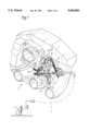
- FIG. 1is a perspective view of a motion transmission mechanism for controlling an internal combustion engine with an input lever connected to an operating element and an output lever connected to an engine power output control element, and
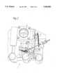
- FIG. 2is a plan view of the motion transmission mechanism.
- an internal combustion engine of which only the air or gas intake section 1 is representedincludes a motion transmission mechanism for transferring control motion from a control input lever 2, such as a gas pedal, to a power control member which is shown in the Figures as a butterfly valve 2.
- the control input lever 2operates, by way of an operating cable, an input lever 5 which is a single-arm pivot lever supported so as to be rotatable about a shaft 6 mounted on a mounting plate 7 (FIG. 2).
- the input lever 5is coupled with an output lever 8 which is rotatably supported on a shaft 9 also mounted on the mounting plate 7.
- the output lever 8is a double-arm lever with a first arm 8a extending from the shaft 9 in one direction and a second arm 8b extending from the shaft 9 in the opposite direction. During operation, both levers pivot concurrently in the same sense.
- the second arm 8a of the output lever 8has a projection provided with a roller 10 which is received in a guide slot 11 formed in the input lever 5.
- the guide slot 11comprises first and second slot section 12, 13 which are arranged at an angle with respect to one another so as to define together approximately the shape of an L.
- the first slot section 12,consequently, extends essentially normal to the second slot section 13 and is also somewhat shorter than the second slot section 13, which extends essentially parallel to a line defined by the shaft and the roller 10 when the linkage is in engine idle position as shown in the figures.
- the input lever 5is engaged by one end of a tension spring 14 whose other end is attached to the free outer end of the first arm 8a of the output lever 8 such that the tension spring 14 extends adjacent the first lever arm 8a and is slightly spaced from the shaft 9.
- the second lever arm 8bis provided, at its free end, with a pivot 15 engaged by one end of an operating rod 16 whose other end engages an intermediate lever 17 connected to a shaft 18 of the throttle valve 3.
- the intermediate lever 17is engaged by a return spring 19 mounted so as to return the throttle valve to its closed position.
- the roller 10is disposed between the pivot 15 and the shaft 9 of the output lever 8 such that the direction of movement of the roller 10 while moving within the first slot section 12 of the guide slot 11 is essentially in line with the force direction of the tension spring 14 in all positions of the input and output levers 5 and 8.
- the roller 10After transition of the roller 10 from the first slot section 12 to the second slot section 13 of the guide slot 11, the roller 10 is increasingly removed from the force line of the spring 14 and comes closer to the shaft 6 of the input lever 5.
Landscapes
- Engineering & Computer Science (AREA)
- Chemical & Material Sciences (AREA)
- Combustion & Propulsion (AREA)
- Mechanical Engineering (AREA)
- General Engineering & Computer Science (AREA)
- Devices For Conveying Motion By Means Of Endless Flexible Members (AREA)
- Control Of Throttle Valves Provided In The Intake System Or In The Exhaust System (AREA)
- Transmission Devices (AREA)
Abstract
Description
Claims (3)
Applications Claiming Priority (2)
| Application Number | Priority Date | Filing Date | Title |
|---|---|---|---|
| DE4430282ADE4430282C1 (en) | 1994-08-26 | 1994-08-26 | Transfer device for IC engine regulation |
| DE4430282.7 | 1994-08-26 |
Publications (1)
| Publication Number | Publication Date |
|---|---|
| US5546904Atrue US5546904A (en) | 1996-08-20 |
Family
ID=6526607
Family Applications (1)
| Application Number | Title | Priority Date | Filing Date |
|---|---|---|---|
| US08/512,535Expired - Fee RelatedUS5546904A (en) | 1994-08-26 | 1995-08-08 | Motion transmission mechanism for controlling an internal combustion engine |
Country Status (3)
| Country | Link |
|---|---|
| US (1) | US5546904A (en) |
| EP (1) | EP0698731B1 (en) |
| DE (2) | DE4430282C1 (en) |
Cited By (1)
| Publication number | Priority date | Publication date | Assignee | Title |
|---|---|---|---|---|
| US6083103A (en)* | 1998-02-25 | 2000-07-04 | New Holland North America, Inc. | Sensor apparatus with butterfly valve for maintaining packing density of moving material |
Citations (7)
| Publication number | Priority date | Publication date | Assignee | Title |
|---|---|---|---|---|
| DE4036953C1 (en)* | 1990-11-20 | 1992-01-30 | Mercedes-Benz Aktiengesellschaft, 7000 Stuttgart, De | Throttle linkage in vehicle - involves link lever with slot and several coil springs |
| US5161507A (en)* | 1990-12-26 | 1992-11-10 | Aisin Seiki Kabushiki Kaisha | Throttle control apparatus |
| US5172688A (en)* | 1991-08-09 | 1992-12-22 | Innovative Medical Design Corp. | Nasal-gastric tube holder |
| US5191866A (en)* | 1992-06-01 | 1993-03-09 | Ford Motor Company | Throttle control system for automotive vehicle |
| US5263449A (en)* | 1992-07-17 | 1993-11-23 | General Motors Corporation | Throttle cam |
| US5297522A (en)* | 1990-04-06 | 1994-03-29 | Audi Ag | Throttle valve |
| US5339783A (en)* | 1993-07-07 | 1994-08-23 | Freightliner Corporation | Throttle breakover apparatus |
Family Cites Families (3)
| Publication number | Priority date | Publication date | Assignee | Title |
|---|---|---|---|---|
| DE3407000C1 (en)* | 1984-02-27 | 1986-01-23 | Dr.Ing.H.C. F. Porsche Ag, 7000 Stuttgart | Throttle control for a multi-cylinder internal combustion engine |
| US4945874A (en)* | 1987-12-19 | 1990-08-07 | Aisan Kogyo Kabushiki Kaisha | Throttle body having interconnecting lever for converting an operational amount of accelerator to an opening of throttle valve |
| US5078111A (en)* | 1991-05-03 | 1992-01-07 | Ford Motor Company | Variable ratio throttle linkage |
- 1994
- 1994-08-26DEDE4430282Apatent/DE4430282C1/ennot_activeExpired - Fee Related
- 1995
- 1995-06-27EPEP95109971Apatent/EP0698731B1/ennot_activeExpired - Lifetime
- 1995-06-27DEDE59500595Tpatent/DE59500595D1/ennot_activeExpired - Fee Related
- 1995-08-08USUS08/512,535patent/US5546904A/ennot_activeExpired - Fee Related
Patent Citations (7)
| Publication number | Priority date | Publication date | Assignee | Title |
|---|---|---|---|---|
| US5297522A (en)* | 1990-04-06 | 1994-03-29 | Audi Ag | Throttle valve |
| DE4036953C1 (en)* | 1990-11-20 | 1992-01-30 | Mercedes-Benz Aktiengesellschaft, 7000 Stuttgart, De | Throttle linkage in vehicle - involves link lever with slot and several coil springs |
| US5161507A (en)* | 1990-12-26 | 1992-11-10 | Aisin Seiki Kabushiki Kaisha | Throttle control apparatus |
| US5172688A (en)* | 1991-08-09 | 1992-12-22 | Innovative Medical Design Corp. | Nasal-gastric tube holder |
| US5191866A (en)* | 1992-06-01 | 1993-03-09 | Ford Motor Company | Throttle control system for automotive vehicle |
| US5263449A (en)* | 1992-07-17 | 1993-11-23 | General Motors Corporation | Throttle cam |
| US5339783A (en)* | 1993-07-07 | 1994-08-23 | Freightliner Corporation | Throttle breakover apparatus |
Cited By (1)
| Publication number | Priority date | Publication date | Assignee | Title |
|---|---|---|---|---|
| US6083103A (en)* | 1998-02-25 | 2000-07-04 | New Holland North America, Inc. | Sensor apparatus with butterfly valve for maintaining packing density of moving material |
Also Published As
| Publication number | Publication date |
|---|---|
| EP0698731A2 (en) | 1996-02-28 |
| DE59500595D1 (en) | 1997-10-09 |
| DE4430282C1 (en) | 1995-09-14 |
| EP0698731B1 (en) | 1997-09-03 |
| EP0698731A3 (en) | 1996-04-10 |
Similar Documents
| Publication | Publication Date | Title |
|---|---|---|
| US5868040A (en) | Gas pedal with friction structure | |
| US4848297A (en) | Arrangement for an automotive vehicle particularly a linkage system | |
| EP2067976B1 (en) | Carburetor and automatic choke assembly for an engine | |
| US5014666A (en) | Load adjustment device | |
| US5423299A (en) | Control valve opening control apparatus | |
| US4721281A (en) | Actuating device for throttle valve | |
| US5161508A (en) | Load adjustment device | |
| US5566910A (en) | Apparatus for adjusting aircraft wing flaps | |
| US6598586B2 (en) | Dual arm choke and throttle control | |
| US5239891A (en) | Cam follower variable ratio throttle linkage | |
| US4995370A (en) | Linked operating device for multiple carburetors | |
| CA1224684A (en) | Progressive throttle positioning system | |
| US4086823A (en) | Transmission and throttle control arrangement | |
| US4875384A (en) | Throttle lever mechanism | |
| US5546904A (en) | Motion transmission mechanism for controlling an internal combustion engine | |
| US4754734A (en) | Injection quantity increasing mechanism for governor in fuel injection pump at engine starting | |
| US6334430B1 (en) | Intake air amount control system for engine | |
| US5068946A (en) | Locking hinge assembly for an aircraft cowling | |
| US4870990A (en) | Double-flow butterfly valve part | |
| JPS6056154A (en) | Throttle controller for industrial engine | |
| US4384559A (en) | Speed limiting device for vehicle driven by internal combustion engine | |
| US4940031A (en) | Setting device for a feed device of an internal combustion engine | |
| JPH0344007B2 (en) | ||
| JPS6039355Y2 (en) | Marine engine control device | |
| US5697253A (en) | Motion transmission arrangement for controlling an internal combustion engine |
Legal Events
| Date | Code | Title | Description |
|---|---|---|---|
| AS | Assignment | Owner name:MERCEDES-BENZ AG, GERMANY Free format text:ASSIGNMENT OF ASSIGNORS INTEREST;ASSIGNORS:PAPENHAGEN, DIETER;MEYER, THORSTEN;REEL/FRAME:007616/0675 Effective date:19950726 | |
| AS | Assignment | Owner name:DAIMLER-BENZ AKTIENGESELLSCHAFT, GERMANY Free format text:MERGER RE-RECORD TO CORRECT THE NUMBER OF MICROFILM PAGES FROM 60 TO 98 AT REEL 9360, FRAME 0937.;ASSIGNOR:MERCEDES-BENZ AG;REEL/FRAME:009827/0145 Effective date:19970605 Owner name:DAIMLER-BENZ AKTIENGESELLSCHAFT, GERMANY Free format text:MERGER;ASSIGNOR:MERCEDES-BENZ AG;REEL/FRAME:009360/0937 Effective date:19970605 | |
| AS | Assignment | Owner name:DAIMLERCHRYSLER AG, GERMANY Free format text:MERGER;ASSIGNOR:DAIMLER-BENZ AKTIENGESELLSCHAFT;REEL/FRAME:010133/0556 Effective date:19990108 | |
| FEPP | Fee payment procedure | Free format text:PAYOR NUMBER ASSIGNED (ORIGINAL EVENT CODE: ASPN); ENTITY STATUS OF PATENT OWNER: LARGE ENTITY | |
| FPAY | Fee payment | Year of fee payment:4 | |
| REMI | Maintenance fee reminder mailed | ||
| LAPS | Lapse for failure to pay maintenance fees | ||
| FP | Lapsed due to failure to pay maintenance fee | Effective date:20040820 | |
| STCH | Information on status: patent discontinuation | Free format text:PATENT EXPIRED DUE TO NONPAYMENT OF MAINTENANCE FEES UNDER 37 CFR 1.362 |