US5546675A - Single tier drying section apparatus - Google Patents
Single tier drying section apparatusDownload PDFInfo
- Publication number
- US5546675A US5546675AUS08/155,990US15599093AUS5546675AUS 5546675 AUS5546675 AUS 5546675AUS 15599093 AUS15599093 AUS 15599093AUS 5546675 AUS5546675 AUS 5546675A
- Authority
- US
- United States
- Prior art keywords
- shell
- dryer
- web
- disposed
- roll
- Prior art date
- Legal status (The legal status is an assumption and is not a legal conclusion. Google has not performed a legal analysis and makes no representation as to the accuracy of the status listed.)
- Expired - Lifetime
Links
Images


Classifications
- D—TEXTILES; PAPER
- D21—PAPER-MAKING; PRODUCTION OF CELLULOSE
- D21F—PAPER-MAKING MACHINES; METHODS OF PRODUCING PAPER THEREON
- D21F5/00—Dryer section of machines for making continuous webs of paper
- D21F5/02—Drying on cylinders
- D21F5/04—Drying on cylinders on two or more drying cylinders
- D21F5/042—Drying on cylinders on two or more drying cylinders in combination with suction or blowing devices
- D—TEXTILES; PAPER
- D21—PAPER-MAKING; PRODUCTION OF CELLULOSE
- D21F—PAPER-MAKING MACHINES; METHODS OF PRODUCING PAPER THEREON
- D21F3/00—Press section of machines for making continuous webs of paper
- D21F3/02—Wet presses
- D21F3/10—Suction rolls, e.g. couch rolls
Definitions
- the present inventionrelates to a single tier drying section apparatus for drying a web of paper.
- the present inventionrelates to a vacuum roll for a single tier drying section.
- Bel-Champis a common law mark of Beloit Corporation covering the aforementioned single tier drying arrangement in which alternate sides of the web are dried during passage of the web through subsequent alternating top and bottom felted dryer sections.
- the Bel-ChampTM conceptenhanced runnability while restraining the web against cross-machine directional shrinkage thereof.
- the 7 single tier drying sectionsinclude a total of 52 vacuum felt rolls, each having a diameter of 26 inches and a shell length of 398 inches.
- Each of the aforementioned vacuum rollsincludes an outer rotatable shell which defines as many as 1 million holes drilled therein. Additionally, each vacuum roll includes a stationary inner shell, which is also drilled and which includes stationary isolating seals extending between the inner stationary shell and the outer rotating shell.
- the aforementioned vacuum roll arrangementsare complex, and a typical vacuum roll may cost in the region of $100,000.
- the present inventionovercomes the aforementioned problem by providing a greatly simplified vacuum roll arrangement in which a stationary vane or fin mechanism is located within a rotatable roll shell.
- the arrangementis such that when the roll shell is rotated by movement of the felt, a clearance exists between the vane or fin without the need for any costly seal arrangement therebetween.
- the purpose of the stationary vane(s) or fin(s) mechanismis to prevent the air encompassed by the vacuum roll from rotating with the roll at the roll velocity. Testing has shown that without the aforementioned mechanism, the rotating air encompassed by the roll provides an effective barrier to air entering the vacuum roll. The shear force created by the internal boundary layer of rotating air is perpendicular to the direction of the air trying to enter through the drilled face of the vacuum roll shell. This impediment to air entering the roll prevents the air flow from attracting, and attaching, the paper web to the dryer fabric as it passes over the vacuum roll, the major purposes of this roll.
- Flow into the rollcan be controlled with a combination of partial vacuum at the roll journal and the clearance between the tips of the fin(s) or vane(s) and the inner surface of the shell.
- Another object of the present inventionis the provision of a single tier drying section apparatus which includes a vacuum roll having a rotatable roll shell and vane means disposed within a chamber defined by the roll shell, without the need for seals or the relatively costly machining of the internal surface of the shell.
- the present inventionrelates to a single tier drying section apparatus and method for drying a web of paper.
- the drying section apparatusincludes a first and a second dryer which are disposed in a single tier for drying the web.
- a vacuum rollis disposed closely adjacent to and between the first and the second dryers for guiding the web from the first to the second dryer.
- a dryer feltextends from the first dryer to and around the vacuum roll.
- the dryer feltthereafter extends from the vacuum roll around the second dryer such that the dryer felt is disposed between the vacuum roll and the web during movement of the web and the dryer felt around the vacuum roll.
- the vacuum rollincludes a rotatable roll shell having a first and a second end.
- the shelldefines an outer surface and an internal chamber which extends between the first and the second end of the shell.
- the shellalso defines a plurality of channels, with each channel extending from the chamber to the outer surface such that the chamber is disposed in fluid communication with the outer surface.
- the first and second dryerdefine a first and second peripheral drying surface, respectively.
- the vacuum rolldefines a cylindrical outer surface which is disposed relative to the first peripheral drying surface at a first distance within the range 0 to 12 inches, and relative to the second peripheral drying surface a second distance within the range 0 to 12 inches.
- the webis disposed between the dryer felt and the first dryer during movement of the web past the first dryer, the web being disposed between the dryer felt and the second dryer during movement of the web past the second dryer.
- the internal chamberextends from the first to the second end of the shell, and the plurality of channels are located between the first and the second end of the shell and are evenly distributed over the outer surface.
- the vane meansalso includes a stationary center shaft which is disposed within and extends along the length of and through the rotatable shell.
- a finextends from the stationary center shaft towards the roll shell such that during rotation of the rotatable shell relative to the fin, air flows through the plurality of channels in order to equalize the pressure differential.
- the finextends radially relative to the center shaft towards the rotatable shell.
- a further finis disposed closely adjacent to the fin and extends substantially parallel to the fin so that the fin and the further fin extend from the center shaft towards the rotatable shell.
- a further finextends from the center shaft towards the roll shell with the further fin being disposed substantially diametrically opposite to the fin.
- the vane meansincludes a stationary axle and a plurality of fins which extend from the axle and radially therefrom towards the rotatable roll shell.
- the arrangementis such that at least some of the apices of the stationary element are disposed in the vicinity of the roll shell.
- Another embodiment of the present inventionincludes a plurality of fins configured as elongate scoops so that relative rotation of the roll shell relative to the fins is accomplished without the need for machining the internal surface of the shell to a close tolerance in order to accommodate a cooperating seal.
- FIG. 1is a side-elevational view showing a single tier drying section incorporating a plurality of vacuum rolls according to the present invention
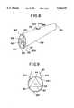
- FIG. 2is an enlarged perspective view of one of the vacuum rolls shown in FIG. 1;
- FIG. 3is an end view of the vacuum roll shown in FIG. 2;
- FIG. 4is a perspective view similar to that shown in FIG. 2, but showing a second embodiment of the present invention
- FIG. 5is an end view of the vacuum roll shown in FIG. 4;
- FIG. 6is a perspective view similar to that shown in FIG. 2, but showing a third embodiment of the present invention.
- FIG. 7is an end view of the vacuum roll shown in FIG. 6;
- FIG. 8is a perspective view similar to that shown in FIG. 2, but showing a fourth embodiment of the present invention.
- FIG. 9is an end view of the vacuum roll shown in FIG. 8;
- FIG. 10is a perspective view similar to that shown in FIG. 2, but showing a fifth embodiment of the present invention.
- FIG. 11is an end view of the vacuum roll shown in FIG. 10;
- FIG. 12is a perspective view similar to that shown in FIG. 2, but showing another embodiment of the present invention.
- FIG. 13is an end view of the vacuum roll shown in FIG. 12.
- the present inventionrelates to a single tier drying section apparatus, generally designated 10, for drying a web of paper W.
- FIG. 1is a side-elevational view of the single tier drying section apparatus 10, for drying the web of paper W and includes a first and a second dryer 12 and 14, respectively, disposed in a single tier, generally designated 16, for drying the web W.
- a vacuum roll, generally designated 18,is disposed closely adjacent to and between the first and second dryers 12 and 14 for guiding the web W from the first to the second dryer 12 and 14, respectively.
- a dryer felt 20extends from the first dryer 12 to and around the vacuum roll 18.
- the dryer felt 20thereafter extends from the vacuum roll 18 around the second dryer 14 such that the dryer felt 20 is disposed between the vacuum roll 18 and the web W during movement of the web W and the dryer felt 20 around the vacuum roll 18.
- FIG. 2is a perspective view of the vacuum roll 18 which includes a rotatable roll shell 22 having a first and a second end 24 and 26, respectively.
- the shell 22defines an outer surface 28 and an internal chamber 30, which extends between the first and the second end 24 and 26, respectively, of the shell 22.
- the shell 22defines a plurality of channels 32,33 and 34. Each of the channels 32-34 extends from the chamber 30 to the outer surface 28 such that the chamber 30 is disposed in fluid communication with the outer surface 28.
- Vane meansare disposed within the chamber 30 for evacuating the chamber 30.
- the flow of air 38is generated by an external air blower or vacuum source 39 for drawing the web W into close conformity with the dryer felt 20 when the web W extends around the vacuum roll 18, as shown in FIG. 3, which is an end view of the roll 18 shown in FIG. 2.
- first and second dryer 12 and 14respectively, define a first and second peripheral drying surface 40 and 42, respectively, as shown in FIG. 1.
- the vacuum roll 18defines the cylindrical outer surface 28.
- the cylindrical outer surface 28 of the vacuum roll 18is disposed relative to the first peripheral drying surface 40 a distance D 1 within the range 0.1 to 5 inches, and relative to the second peripheral drying surface 42 a second distance D 2 within the range 0 to 12 inches.
- the web Wis disposed between the dryer felt 20 and the first dryer 12 during movement of the web W past the first dryer 12. Additionally, the web W is disposed between the dryer felt 20 and the second dryer 14 during movement of the web W past the second dryer 14.
- the internal chamber 30extends from the first to the second end 24,26 of the shell 22.
- the plurality of channels 32 to 34are located between the first and the second end 24 and 26, respectively, of the shell 22 and are evenly distributed over the outer surface 28.
- the vane meansgenerally designated 36, as shown in FIG. 2, further includes a stationary center shaft 50 disposed within and extending along the length of and through the rotatable shell 22.
- FIG. 3is an end view of the vacuum roll 18 shown in FIG. 2 and shows a fin 52 extending from the stationary center shaft 50 towards the roll shell 22.
- the fin 52extends generally in a radial direction relative to the center shaft 50 towards the rotatable roll shell 22.
- a further fin 54is disposed closely adjacent to the fin 52 and extends substantially parallel to the fin 52 so that the fin 52 and further fin 54, respectively, extend from the center shaft 50 towards the rotatable shell 22.
- FIG. 4is a perspective view of a roll shell 18C according to a second embodiment of the present invention.
- the further fin 54cextends radially from the center shaft 50c towards the roll shell 22c, with the further fin 54c being disposed substantially diametrically opposite to the fin 52c.
- FIG. 5is an end view of the roll 18c shown in FIG. 4.
- FIG. 6is a perspective view of a third embodiment of the present invention.
- the vane means 36dincludes a stationary axle 50d and a plurality of fins 58,59,60 and 61 extending from the axle 50d and radially therefrom towards the rotatable roll shell 22d.
- FIG. 7is an end view of the arrangement shown in FIG. 6.
- the vane means 36fincludes a stationary element 62 of substantially triangular cross-sectional configuration.
- the arrangementis such that at least some of the apices 64,65 and 66 of the stationary element 62 are such that air flows, as shown by arrow 38f, through the plurality of channels 32f to 34f into the chamber 30f for holding the web Wf onto the dryer felt 20f.
- the plurality of fins 58g,59g,60g and 61gare configured as scoops such that relative rotation of the roll shell 22g relative to the fins 58g to 61g tends to scoop air from within the chamber 30g, expelling such air, as shown by arrow 38g, through the ends 24g,26g of the shell 22g.
- FIG. 11is an end view of the arrangement shown in FIG. 10.
- FIG. 12is a perspective view of another embodiment of the present invention which includes a single fin 54h, and FIG. 13 is an end view of the vacuum roll shown in FIG. 12.
- the gap between the tip of the vane or fin to the internal diameter of the vacuum rollis within the range 0.001 inches to 6 inches.
- the present inventionprovides an inexpensive means of fabricating a vacuum roll for a single tier drying section and overcomes the need for relatively complex internal seals and the need for the maintenance of such seals.
Landscapes
- Paper (AREA)
- Drying Of Solid Materials (AREA)
Abstract
Description
Claims (11)
Priority Applications (11)
| Application Number | Priority Date | Filing Date | Title |
|---|---|---|---|
| US08/155,990US5546675A (en) | 1993-11-22 | 1993-11-22 | Single tier drying section apparatus |
| PL94314533APL314533A1 (en) | 1993-11-22 | 1994-11-21 | Single-layer drying section apparatus |
| JP7515182AJP2761980B2 (en) | 1993-11-22 | 1994-11-21 | Single row drying unit |
| CN94194255ACN1039930C (en) | 1993-11-22 | 1994-11-21 | A single tier drying section apparatus |
| DE69417437TDE69417437D1 (en) | 1993-11-22 | 1994-11-21 | DEVICE FOR A SCREEN DRYING SECTION |
| PCT/US1994/013465WO1995014812A1 (en) | 1993-11-22 | 1994-11-21 | A single tier drying section apparatus |
| CA002177083ACA2177083A1 (en) | 1993-11-22 | 1994-11-21 | A single tier drying section apparatus |
| BR9408109ABR9408109A (en) | 1993-11-22 | 1994-11-21 | Single row dryer section appliance |
| KR1019960702712AKR100294803B1 (en) | 1993-11-22 | 1994-11-21 | Single layer drying unit |
| EP95902656AEP0730690B1 (en) | 1993-11-22 | 1994-11-21 | A single tier drying section apparatus |
| FI962136AFI962136A7 (en) | 1993-11-22 | 1996-05-21 | Single-row drying unit |
Applications Claiming Priority (1)
| Application Number | Priority Date | Filing Date | Title |
|---|---|---|---|
| US08/155,990US5546675A (en) | 1993-11-22 | 1993-11-22 | Single tier drying section apparatus |
Publications (1)
| Publication Number | Publication Date |
|---|---|
| US5546675Atrue US5546675A (en) | 1996-08-20 |
Family
ID=22557617
Family Applications (1)
| Application Number | Title | Priority Date | Filing Date |
|---|---|---|---|
| US08/155,990Expired - LifetimeUS5546675A (en) | 1993-11-22 | 1993-11-22 | Single tier drying section apparatus |
Country Status (11)
| Country | Link |
|---|---|
| US (1) | US5546675A (en) |
| EP (1) | EP0730690B1 (en) |
| JP (1) | JP2761980B2 (en) |
| KR (1) | KR100294803B1 (en) |
| CN (1) | CN1039930C (en) |
| BR (1) | BR9408109A (en) |
| CA (1) | CA2177083A1 (en) |
| DE (1) | DE69417437D1 (en) |
| FI (1) | FI962136A7 (en) |
| PL (1) | PL314533A1 (en) |
| WO (1) | WO1995014812A1 (en) |
Cited By (8)
| Publication number | Priority date | Publication date | Assignee | Title |
|---|---|---|---|---|
| US5737848A (en)* | 1995-03-16 | 1998-04-14 | Voith Sulzer Papiermaschinen Gmbh | Guide roll arrangement for paper machine drying section |
| US5876383A (en)* | 1997-09-30 | 1999-03-02 | Grooters; Robert K. | Cannula |
| US6079116A (en)* | 1998-11-06 | 2000-06-27 | Valmet-Karlstad Ab | Duct configuration for a through-air drying apparatus in a papermaking machine |
| US6151797A (en)* | 1998-04-30 | 2000-11-28 | Fleissner Gmbh & Co., Maschinenfabrik | Device for heat treatment of permeable webs of goods |
| US6256903B1 (en)* | 1996-08-23 | 2001-07-10 | Research, Incorporated | Coating dryer system |
| WO2003027386A1 (en)* | 2001-09-26 | 2003-04-03 | Metso Paper Karlstad Ab | Suction roll with internal vanes |
| US7040038B1 (en)* | 1998-09-02 | 2006-05-09 | Metso Paper Usa, Inc. | Apparatus for processing permeable or semi-permeable webs |
| US20090070803A1 (en)* | 2007-09-10 | 2009-03-12 | The Directv Group, Inc. | Method and system for real-time reconciliation for unused content |
Families Citing this family (4)
| Publication number | Priority date | Publication date | Assignee | Title |
|---|---|---|---|---|
| FI98386C (en)* | 1996-03-07 | 1997-06-10 | Valmet Corp | Suction roll / suction cylinder |
| DE69827583T2 (en) | 1997-05-23 | 2005-03-31 | Daicel Chemical Industries, Ltd., Sakai | POLYMERIZABLE ADAMANTAN DERIVATIVES AND METHOD FOR THE PRODUCTION THEREOF |
| CN105862487A (en)* | 2015-01-20 | 2016-08-17 | 陈万勇 | Rapid drying cylinder of toilet paper machine |
| CN104988785B (en)* | 2015-08-10 | 2017-01-04 | 苏州普京真空技术有限公司 | A kind of vacuum roller |
Citations (16)
| Publication number | Priority date | Publication date | Assignee | Title |
|---|---|---|---|---|
| US3946497A (en)* | 1973-01-15 | 1976-03-30 | United Merchants And Manufacturers, Inc. | Apparatus for treating textile fabric to retard inflammability |
| WO1990001085A1 (en)* | 1988-07-22 | 1990-02-08 | Beloit Corporation | A dryer apparatus for drying a web |
| US4905379A (en)* | 1987-02-13 | 1990-03-06 | Beloit Corporation | Intermediate vacuum roll for dryer |
| US4949475A (en)* | 1989-12-20 | 1990-08-21 | Beloit Corporation | Temperature compensated ventilating roll |
| DE3913292A1 (en)* | 1989-04-22 | 1990-10-25 | Voith Gmbh J M | CYLINDERS FOR GUIDING GOODS |
| US4970805A (en)* | 1987-02-13 | 1990-11-20 | Beloit Corporation | Transfer apparatus for transferring a tail of a web |
| US4980979A (en)* | 1987-02-13 | 1991-01-01 | Beloit Corporation | Vacuum roll transfer apparatus |
| US5015336A (en)* | 1989-10-31 | 1991-05-14 | Beloit Corporation | Felt turning suction roll |
| EP0428471A2 (en)* | 1989-10-31 | 1991-05-22 | Beloit Corporation | A vacuum guide roll apparatus |
| US5020242A (en)* | 1989-03-08 | 1991-06-04 | J. M. Voith Gmbh | Guide roll for a porous belt |
| US5024729A (en)* | 1989-08-18 | 1991-06-18 | Valmet Paper Machinery Inc. | Suction roll with turbulence suppression element |
| EP0432571A2 (en)* | 1989-12-12 | 1991-06-19 | Valmet Paper Machinery Inc. | Suction roll for a paper machine and a method for producing a desired pressure profile for a suction roll |
| US5031338A (en)* | 1987-02-13 | 1991-07-16 | Beloit Corporation | Vacuum roll transfer apparatus |
| US5152078A (en)* | 1987-02-13 | 1992-10-06 | Beloit Corporation | Vacuum roll transfer apparatus |
| US5347728A (en)* | 1991-07-15 | 1994-09-20 | Sulzer Escher Wyss Gmbh | Suction roll, especially for a paper web drier |
| US5371954A (en)* | 1991-12-19 | 1994-12-13 | Sulzer-Escher Wyss Gmbh | Method and apparatus for the guiding of fibre webs |
Family Cites Families (1)
| Publication number | Priority date | Publication date | Assignee | Title |
|---|---|---|---|---|
| FI83680C (en)* | 1988-03-09 | 1991-08-12 | Valmet Paper Machinery Inc | FOERFARANDE OCH ANORDNING VID DRAGNINGEN AV BANAN I EN PAPPERSMASKIN SAMT CYLINDER FOER ANVAENDNING VID DRAGNINGEN AV BANAN. |
- 1993
- 1993-11-22USUS08/155,990patent/US5546675A/ennot_activeExpired - Lifetime
- 1994
- 1994-11-21KRKR1019960702712Apatent/KR100294803B1/ennot_activeExpired - Fee Related
- 1994-11-21CNCN94194255Apatent/CN1039930C/ennot_activeExpired - Fee Related
- 1994-11-21BRBR9408109Apatent/BR9408109A/ennot_activeApplication Discontinuation
- 1994-11-21DEDE69417437Tpatent/DE69417437D1/ennot_activeExpired - Lifetime
- 1994-11-21PLPL94314533Apatent/PL314533A1/enunknown
- 1994-11-21WOPCT/US1994/013465patent/WO1995014812A1/enactiveIP Right Grant
- 1994-11-21CACA002177083Apatent/CA2177083A1/ennot_activeAbandoned
- 1994-11-21JPJP7515182Apatent/JP2761980B2/ennot_activeExpired - Lifetime
- 1994-11-21EPEP95902656Apatent/EP0730690B1/ennot_activeExpired - Lifetime
- 1996
- 1996-05-21FIFI962136Apatent/FI962136A7/enunknown
Patent Citations (16)
| Publication number | Priority date | Publication date | Assignee | Title |
|---|---|---|---|---|
| US3946497A (en)* | 1973-01-15 | 1976-03-30 | United Merchants And Manufacturers, Inc. | Apparatus for treating textile fabric to retard inflammability |
| US4905379A (en)* | 1987-02-13 | 1990-03-06 | Beloit Corporation | Intermediate vacuum roll for dryer |
| US5152078A (en)* | 1987-02-13 | 1992-10-06 | Beloit Corporation | Vacuum roll transfer apparatus |
| US4970805A (en)* | 1987-02-13 | 1990-11-20 | Beloit Corporation | Transfer apparatus for transferring a tail of a web |
| US4980979A (en)* | 1987-02-13 | 1991-01-01 | Beloit Corporation | Vacuum roll transfer apparatus |
| US5031338A (en)* | 1987-02-13 | 1991-07-16 | Beloit Corporation | Vacuum roll transfer apparatus |
| WO1990001085A1 (en)* | 1988-07-22 | 1990-02-08 | Beloit Corporation | A dryer apparatus for drying a web |
| US5020242A (en)* | 1989-03-08 | 1991-06-04 | J. M. Voith Gmbh | Guide roll for a porous belt |
| DE3913292A1 (en)* | 1989-04-22 | 1990-10-25 | Voith Gmbh J M | CYLINDERS FOR GUIDING GOODS |
| US5024729A (en)* | 1989-08-18 | 1991-06-18 | Valmet Paper Machinery Inc. | Suction roll with turbulence suppression element |
| EP0428471A2 (en)* | 1989-10-31 | 1991-05-22 | Beloit Corporation | A vacuum guide roll apparatus |
| US5015336A (en)* | 1989-10-31 | 1991-05-14 | Beloit Corporation | Felt turning suction roll |
| EP0432571A2 (en)* | 1989-12-12 | 1991-06-19 | Valmet Paper Machinery Inc. | Suction roll for a paper machine and a method for producing a desired pressure profile for a suction roll |
| US4949475A (en)* | 1989-12-20 | 1990-08-21 | Beloit Corporation | Temperature compensated ventilating roll |
| US5347728A (en)* | 1991-07-15 | 1994-09-20 | Sulzer Escher Wyss Gmbh | Suction roll, especially for a paper web drier |
| US5371954A (en)* | 1991-12-19 | 1994-12-13 | Sulzer-Escher Wyss Gmbh | Method and apparatus for the guiding of fibre webs |
Cited By (8)
| Publication number | Priority date | Publication date | Assignee | Title |
|---|---|---|---|---|
| US5737848A (en)* | 1995-03-16 | 1998-04-14 | Voith Sulzer Papiermaschinen Gmbh | Guide roll arrangement for paper machine drying section |
| US6256903B1 (en)* | 1996-08-23 | 2001-07-10 | Research, Incorporated | Coating dryer system |
| US5876383A (en)* | 1997-09-30 | 1999-03-02 | Grooters; Robert K. | Cannula |
| US6151797A (en)* | 1998-04-30 | 2000-11-28 | Fleissner Gmbh & Co., Maschinenfabrik | Device for heat treatment of permeable webs of goods |
| US7040038B1 (en)* | 1998-09-02 | 2006-05-09 | Metso Paper Usa, Inc. | Apparatus for processing permeable or semi-permeable webs |
| US6079116A (en)* | 1998-11-06 | 2000-06-27 | Valmet-Karlstad Ab | Duct configuration for a through-air drying apparatus in a papermaking machine |
| WO2003027386A1 (en)* | 2001-09-26 | 2003-04-03 | Metso Paper Karlstad Ab | Suction roll with internal vanes |
| US20090070803A1 (en)* | 2007-09-10 | 2009-03-12 | The Directv Group, Inc. | Method and system for real-time reconciliation for unused content |
Also Published As
| Publication number | Publication date |
|---|---|
| BR9408109A (en) | 1997-08-05 |
| KR960705985A (en) | 1996-11-08 |
| DE69417437D1 (en) | 1999-04-29 |
| EP0730690B1 (en) | 1999-03-24 |
| JP2761980B2 (en) | 1998-06-04 |
| CN1039930C (en) | 1998-09-23 |
| WO1995014812A1 (en) | 1995-06-01 |
| CA2177083A1 (en) | 1995-06-01 |
| EP0730690A1 (en) | 1996-09-11 |
| KR100294803B1 (en) | 2001-09-17 |
| PL314533A1 (en) | 1996-09-16 |
| JPH09500179A (en) | 1997-01-07 |
| FI962136A7 (en) | 1996-07-05 |
| FI962136A0 (en) | 1996-05-21 |
| CN1135779A (en) | 1996-11-13 |
Similar Documents
| Publication | Publication Date | Title |
|---|---|---|
| US5829164A (en) | Method and machine for drying a material web with guide rollers | |
| US5546675A (en) | Single tier drying section apparatus | |
| US4882854A (en) | Guide roll apparatus for a dryer of a paper machine drying section | |
| JP2688072B2 (en) | Processing method and drying unit of multi-cylinder dryer of paper machine | |
| US5515619A (en) | Flexibly mounted sealing strips of a vacuum roll for a web dryer | |
| KR100460517B1 (en) | Blowing apparatus in paper machine or the like | |
| US4980979A (en) | Vacuum roll transfer apparatus | |
| US5782009A (en) | Device for guiding a sheet of fibrous material in a single-row dryer part | |
| US4905379A (en) | Intermediate vacuum roll for dryer | |
| US5031338A (en) | Vacuum roll transfer apparatus | |
| US4932138A (en) | Method and device for threading a web around drying cylinders | |
| US4974340A (en) | Vacuum guide roll apparatus | |
| US5509215A (en) | Method and device for stabilization of a paper web in a group of cylinders in a drying section of a paper machine | |
| FI82502C (en) | Method and apparatus in the drying section of a paper machine to effect the tip drawing of the web | |
| US5152078A (en) | Vacuum roll transfer apparatus | |
| US5996244A (en) | Roll for a paper machine, in particular for a paper drying device, and dryer group for a paper machine | |
| US5542192A (en) | Vacuum roll apparatus | |
| US6145218A (en) | Drying section and method for drying a material web in such a drying section | |
| US4888883A (en) | Drawing a web through a multi-cylinder drying section | |
| US20030051849A1 (en) | Suction roll of a paper machine | |
| US5635034A (en) | Suction roll or cylinder and method for removing air from a suction roll or cylinder | |
| CN112189123A (en) | Grooved and perforated turning roll for a fiber web machine | |
| US5020238A (en) | Vacuum guide roll apparatus | |
| EP0960973A2 (en) | A dryer felt device | |
| JPH07167558A (en) | Device for guiding a ribbon of textile material to be dried |
Legal Events
| Date | Code | Title | Description |
|---|---|---|---|
| AS | Assignment | Owner name:BELOIT TECHNOLOGIES, INC., DELAWARE Free format text:ASSIGNMENT OF ASSIGNORS INTEREST;ASSIGNORS:MCGRAW, WILLIAM R.;PULKOWSKI, JEFFREY H.;REEL/FRAME:006778/0763 Effective date:19931118 | |
| FEPP | Fee payment procedure | Free format text:PAYOR NUMBER ASSIGNED (ORIGINAL EVENT CODE: ASPN); ENTITY STATUS OF PATENT OWNER: LARGE ENTITY | |
| STCF | Information on status: patent grant | Free format text:PATENTED CASE | |
| REMI | Maintenance fee reminder mailed | ||
| FPAY | Fee payment | Year of fee payment:4 | |
| SULP | Surcharge for late payment | ||
| AS | Assignment | Owner name:METSO PAPER INC., FINLAND Free format text:ASSIGNMENT OF ASSIGNORS INTEREST;ASSIGNOR:BELOIT TECHNOLOGIES, INC.;REEL/FRAME:012119/0182 Effective date:20010816 Owner name:MITSUBISHI HEAVY INDUSTRIES, LTD., JAPAN Free format text:ASSIGNMENT OF ASSIGNORS INTEREST;ASSIGNOR:BELOIT TECHNOLOGIES, INC.;REEL/FRAME:012119/0182 Effective date:20010816 | |
| FPAY | Fee payment | Year of fee payment:8 | |
| FPAY | Fee payment | Year of fee payment:12 | |
| AS | Assignment | Owner name:VALMET TECHNOLOGIES, INC., FINLAND Free format text:CHANGE OF NAME;ASSIGNOR:METSO PAPER, INC.;REEL/FRAME:032551/0426 Effective date:20131212 |