US5546444A - Methods and apparatus for communicating data via a cellular network control channel - Google Patents
Methods and apparatus for communicating data via a cellular network control channelDownload PDFInfo
- Publication number
- US5546444A US5546444AUS08/212,039US21203994AUS5546444AUS 5546444 AUS5546444 AUS 5546444AUS 21203994 AUS21203994 AUS 21203994AUS 5546444 AUS5546444 AUS 5546444A
- Authority
- US
- United States
- Prior art keywords
- data
- cellular
- msc
- control channel
- message
- Prior art date
- Legal status (The legal status is an assumption and is not a legal conclusion. Google has not performed a legal analysis and makes no representation as to the accuracy of the status listed.)
- Expired - Lifetime
Links
- 230000001413cellular effectEffects0.000titleclaimsabstractdescription248
- 238000000034methodMethods0.000titleclaimsabstractdescription63
- 238000004891communicationMethods0.000claimsabstractdescription282
- 238000013480data collectionMethods0.000claimsabstractdescription127
- 230000004044responseEffects0.000claimsabstractdescription92
- 230000008569processEffects0.000claimsabstractdescription23
- 230000010267cellular communicationEffects0.000claimsdescription144
- 238000012545processingMethods0.000claimsdescription41
- 238000012544monitoring processMethods0.000claimsdescription25
- 230000005055memory storageEffects0.000claimsdescription21
- 230000001934delayEffects0.000claimsdescription5
- 108091006146ChannelsProteins0.000description140
- 230000005540biological transmissionEffects0.000description50
- 230000000694effectsEffects0.000description15
- 238000010586diagramMethods0.000description13
- 230000008901benefitEffects0.000description12
- 230000006870functionEffects0.000description9
- 238000005265energy consumptionMethods0.000description8
- 230000009471actionEffects0.000description6
- 230000000977initiatory effectEffects0.000description6
- 238000001228spectrumMethods0.000description6
- 238000012552reviewMethods0.000description5
- 238000001514detection methodMethods0.000description4
- 238000009434installationMethods0.000description4
- 238000007726management methodMethods0.000description4
- 238000012546transferMethods0.000description4
- 238000010200validation analysisMethods0.000description4
- 125000004122cyclic groupChemical group0.000description3
- 230000003111delayed effectEffects0.000description2
- 238000009826distributionMethods0.000description2
- 238000011156evaluationMethods0.000description2
- 230000011664signalingEffects0.000description2
- 238000003860storageMethods0.000description2
- 238000012384transportation and deliveryMethods0.000description2
- IRLPACMLTUPBCL-KQYNXXCUSA-N5'-adenylyl sulfateChemical compoundC1=NC=2C(N)=NC=NC=2N1[C@@H]1O[C@H](COP(O)(=O)OS(O)(=O)=O)[C@@H](O)[C@H]1OIRLPACMLTUPBCL-KQYNXXCUSA-N0.000description1
- 102100022002CD59 glycoproteinHuman genes0.000description1
- 101000897400Homo sapiens CD59 glycoproteinProteins0.000description1
- 238000004458analytical methodMethods0.000description1
- 238000013459approachMethods0.000description1
- 238000004364calculation methodMethods0.000description1
- 239000003990capacitorSubstances0.000description1
- 230000023402cell communicationEffects0.000description1
- 230000001276controlling effectEffects0.000description1
- 238000007796conventional methodMethods0.000description1
- 238000013500data storageMethods0.000description1
- 238000012217deletionMethods0.000description1
- 230000037430deletionEffects0.000description1
- 238000013461designMethods0.000description1
- 230000004069differentiationEffects0.000description1
- 230000002349favourable effectEffects0.000description1
- 238000003780insertionMethods0.000description1
- 230000037431insertionEffects0.000description1
- 230000002452interceptive effectEffects0.000description1
- 238000012423maintenanceMethods0.000description1
- 238000004519manufacturing processMethods0.000description1
- 238000010295mobile communicationMethods0.000description1
- 238000012986modificationMethods0.000description1
- 230000004048modificationEffects0.000description1
- 238000012806monitoring deviceMethods0.000description1
- 230000003287optical effectEffects0.000description1
- 230000001105regulatory effectEffects0.000description1
- 230000007781signaling eventEffects0.000description1
- 235000014214soft drinkNutrition0.000description1
- 230000026676system processEffects0.000description1
- 230000007704transitionEffects0.000description1
- 238000013519translationMethods0.000description1
- 238000012795verificationMethods0.000description1
- 230000000007visual effectEffects0.000description1
Images


Classifications
- H—ELECTRICITY
- H04—ELECTRIC COMMUNICATION TECHNIQUE
- H04W—WIRELESS COMMUNICATION NETWORKS
- H04W4/00—Services specially adapted for wireless communication networks; Facilities therefor
- H04W4/12—Messaging; Mailboxes; Announcements
- H—ELECTRICITY
- H04—ELECTRIC COMMUNICATION TECHNIQUE
- H04W—WIRELESS COMMUNICATION NETWORKS
- H04W84/00—Network topologies
- H04W84/02—Hierarchically pre-organised networks, e.g. paging networks, cellular networks, WLAN [Wireless Local Area Network] or WLL [Wireless Local Loop]
- H04W84/022—One-way selective calling networks, e.g. wide area paging
Definitions
- the present inventionrelates generally to data communications systems and more particularly relates to a method and apparatus for communicating data via a cellular network control channel of a cellular mobile radiotelephone system.
- a conventional radio communications systemuses a base station transceiver located at a site for favorable radio propagation and a set of transceivers typically located in vehicles, such as for police or trucking dispatching systems, or at remote equipment sites that communicate data in response to a command signal from the base station transceiver.
- Most radio communications systemsare useful for conducting communications between short distances, such as within the boundaries of a town or city, via a very high frequency (VHF) radio link.
- VHFvery high frequency
- two-way radiosare not widely accepted for general purpose communications.
- the use of two-way radiosis generally regulated by the Federal Communications Commission (FCC) and the allocated frequency spectrum is relatively limited.
- FCCFederal Communications Commission
- the quality of communicationsis subject to the propagation conditions between communications sites.
- Two-way radio equipmentis generally large and heavy and, as a result, is unlikely to be carried by a user at all times or to be installed in small or existing equipment.
- CMRcellular mobile radiotelephone
- PSTNpublic switched telephone network
- Typical CMR systemsare characterized by dividing a radio coverage area into smaller coverage areas or "cell" using low power transmitters and coverage-restricted receivers. As shown in U.S. Pat. Nos. 3,906,166 and 4,268,722, the limited coverage area enables the radio channels used in one cell to be reused in another cell.
- a CMR systemcan supply two-way communications for an array of cells, thereby supplying communications for a much wider area than conventional two-way radios.
- radiotelephonesgenerally offer both voice and data communications capabilities and, accordingly, the radiotelephone service is generally supplied at a cost that is commensurate with the combined voice and data services. Nevertheless, this combination of both voice and data communications may exceed a user's requirement for communicating by only voice or data. In addition, real-time voice or data communications is not always desirable by a user who wishes only to receive a message without having a current activity disturbed. Similar to two-way radios, the frequency spectrum for the CMR system radio channels, particularly voice channels, is a limited resource.
- Paging systemsinclude pagers, which are miniature receivers, and at least one paging terminal having a transmitter that covers a selected geographic area containing numerous pagers.
- a pageris generally tuned to a particular tone or data bit-modulated radio frequency that is shared with many other pagers.
- a particular sequence of tones or data bitsis used as an address or the identification of a selected pager. Reception of the particular sequence activates an acoustic, tactile, or visible alert, thereby indicating that a call has been placed to the paging terminal from a telephone connected to the PSTN and generally communicated via the transmitter to the pager.
- the paging devicemay receive a voice or a data message following the alert, or the alert alone may simply indicate to the user that a call was made and a prearranged action should be taken.
- This type of pagerforms a one-way messaging system because it does not permit the party initiating the page to know if the page has actually been received by the addressed pager.
- the paged partyTo respond to a page received via the conventional one-way paging system, the paged party typically must find an available conventional telephone and initiate a telephone call to the party that initiated the page. Alternatively, the paged party can place a responsive call by use of a mobile radiotelephone, if available.
- U.S. Pat. No. 5,148,473describes a pager and radiotelephone apparatus having the combination of a radio pager section and a cellular radiotelephone section. To answer a page, the user simply places a call via the CMR system. The pager also allows the user to screen incoming call to determine which of the received messages to return, thereby eliminating the CMR system service costs associated with unwanted calls.
- any acknowledgment of a received page by this apparatusrequires use of the relatively limited spectrum for voice channels of the CMR system.
- Paging systemshaving two-way communications capability for receiving a page and transmitting an acknowledge receipt of a page are also known.
- One such systemenables a pager having acknowledgment capability to immediately communicate a response to the calling party after receiving the initial page contact.
- the responsemay be a voice, numeric, or alphanumeric message informing the originator of the page communication that the message was successfully received by the page, and may further offer a reply to the received message.
- This page acknowledgment systemgenerally includes a single central transmitter covering a certain geographic area and one or more acknowledgment system receivers for receiving acknowledgment signals from the pagers.
- the acknowledgment system receiverscan communicate acknowledgment messages to the central transmitter via either a wire or wireless link.
- the number of acknowledgment system receiversis a function of the transmitting power of the acknowledgment transmitter associated with each of the pagers.
- the transmitter power of pagersis generally low, typically less than one watt, based upon the requirement for portability of the pager and the necessity to minimize the size of the battery for powering the transmitter.
- Such paging acknowledgment systemsare most useful for local area "on-site" communications systems in view of the power limitations of the transmitters associated with the pagers.
- U.S. Pat. No. 5,005,014describes a wide area paging communications system for efficiently transmitting acknowledgment signals received from a group of portable communications receivers to a central station for ultimate distribution to the message originators.
- the wide area communications systemincludes a group of cells, a central transmitter station, and a group of remote transmitter stations and remote receiver stations.
- a remote transmitter stationis centrally located within each cell to provide message transmissions to a set of portable communications receivers within the cell.
- a remote receiver stationis located in each cell to receive acknowledgment signals from the portable communications receivers in response to receiving messages.
- Messagesare input into the communications system via a paging terminal located at the central station and subsequently distributed to the remote transmitters for communication to the portable communications receivers.
- a messageis received by the intended portable communications receiver, it will confirm receipt of the message by sending an acknowledgment message that is received by at least one of the remote receiver stations and forwarded to the central transmitter station via a remote transmitter station.
- U.S. Pat. No. 4,644,351describes a communications system for transmitting messages via a radio channel from one of a group of fixed paging central sites having different coverage areas to a set of remote paging units.
- Each paging central siteincludes a group of base stations that cover a relatively large and essentially contiguous geographic area and are controlled by a network control processor.
- Each remote paging unitis assigned an unique address and is associated with one of the central paging sites.
- a message for a selected remote paging unitis received at a paging central site via a PSTN or another value added network (VAN), it is stored and a file is searched to discover the location of the selected remote paging unit.
- VANvalue added network
- the message and the addressare then transmitted by the paging central site located in the radio coverage area most likely to contain the selected remote paging unit.
- the selected remote paging unitreceives the message, it stores the message and returns a message received acknowledgment to the paging central site, which, in turn, deletes the message from its storage.
- the remote paging unitreceives and acknowledges its messages regardless of the central site radio coverage in which the unit is located.
- paging acknowledgment systemsrequire a large capital investment for the purchase and installation of equipment to implement a two-way communications system that covers a wide communications area because the number of acknowledgment receivers (and transmitters) in a paging acknowledgment system is a function of the limited transmitting power of the transmitter associated with each of the pagers.
- the paging industryis interested in supplying a page acknowledgment to subscribers of paging services, the cost of implementing the paging acknowledgment system has discouraged many service providers from installing such paging acknowledgment systems.
- the present inventionadapts the existing architecture of a CMR system in a efficient and cost-effective manner to support data communications via the CMR system, including the collection and reporting of data recorded at remote sites and the acknowledgment of a page message.
- the present inventionsolves the problems of the prior art by providing an apparatus and method for communicating data via a cellular network control channel of a CMR system.
- Telecommunications service suppliersincluding a company related to the assignee of this application, BellSouth Mobility, have already installed the necessary equipment to support nationwide communications via CMR networks.
- the inventorshave recognized that the CMR system is an existing communications architecture which can be adapted in a novel manner to supply either one or two-way data communications with minimal impact upon the well known voice communications offered by the cellular mobile radiotelephone network.
- the present inventiontakes advantage of this installed base of communication equipment by using the control channel of the CMR system for data communications between a central location and numerous remote sites. In this manner, the present invention conserves the valuable frequency spectrum allocated for the voice channels that support normal telephone conversations on the CMR system.
- the present inventionis a data message system for communicating data collected from remote data sources.
- the data message systemincludes sets of data reporting devices, at least one mobile switching center (MSC) of a CMR system, and a data collection system connected to the MSC.
- Each data reporting deviceincludes a monitor and a cellular communications device.
- the monitorwhich is connected to a remote data source, monitors the operation of the remote data source to obtain selected data.
- the cellular communications deviceis connected to a corresponding monitor and, in response to selected data, transmits a data message containing the selected data.
- the MSCreceives data messages via a cellular network control channel of the CMR system from the cellular communications devices operating within coverage areas of the CMR system.
- the MSCsends the data messages to the data collection system via a first communications link.
- the data collection systemwhich is connected to a memory storage device, stores each data message and thereafter processes the stored data messages.
- the data collection systemcan accept data communications that are compatible with EIA/TIA Interim Standard 41 (IS-41) or any other vendor proprietary protocol.
- the data collection systemalso can transmit the stored data message to a data processing system via a second communications link.
- the data processing systemwhich also operates to store and/or process the contents of the data message, is typically located at a site remote from the data collection system. This permits processing of selected data at a central location that is more convenient for the user, rather than conducting such operations at the location for the data collection system.
- the data collection system and the data processing systemare typically located at separate sites, the operations of the data collection and the data processing system also can be combined or otherwise integrated by installing those systems at the same physical location.
- selected data acquired from various remote sitescan be communicated to a single location.
- the data sourcestypically include utility meters, community antenna television (CATV) pay-per-view (PPV) terminals, vending equipment, and security alarm systems.
- the selected datadescribes certain parameters of operation or performance by each of the data sources. For example, if the data source is an electrical utility meter located proximate to the consumer's location, then a utility can obtain parameters, such as the power demand for a certain time interval, recorded by a monitor connected to the source and communicated via the control channel of the CMR system.
- the monitorincludes a recorder for recording the selected data during at least one predetermined time period.
- the recordercan add to the selected data a time tag indicating the relative time for the start of the predetermined time period.
- the use of the time tagpermits correlation of the selected data to a specific time, thereby assisting processing of the collected data at a later date.
- the cellular communications devicewhich can be implemented as a cellular radiotelephone transceiver, transmits the selected data to the MSC in a data-type format via the control channel of the CMR system. This conserves the use of the frequency spectrum associated with the voice channel of the CMR system and avoids interfering with call traffic on the voice channel.
- the data transmission by the cellular communications devicecan be initiated in response to a status signal output by the monitor. This status signal indicates that the monitor has recorded selected data from the data source and, based upon completion of this data collection operation, prompts the cellular communications device to transmit the stored selected data.
- the cellular communications devicetypically transmits the selected data during certain off-peak times of operation for the CMR system. Specifically, the cellular communications device monitors the cellular network control channel to detect a stream of busy idle bits. The status of each of the busy idle bits indicates whether at least one cellular source has initiated a cellular communication with the MSC via the cellular network control channel during a particular time period. A busy idle bit set to the binary value of one indicates that the control channel is busy. Based upon the status of each of the busy idle bits transmitted during a selected time period, the cellular communications device determines the level of communications activity on the cellular network control channel. The cellular communications device transmits the data message to the MSC during a "window of opportunity" when the results of this monitoring operation indicate that the communications on the control channel have been at a level which would permit a data transmission on a noninterference basis.
- the cellular communications devicecan transmit the data message at a selected time period that represents a desirable time for such communications, such as the early morning hours when call traffic on the CMR system is normally at a low level.
- the cellular communications deviceincludes a clock that outputs a clock signal upon expiration of a time interval, which is a time that is typically associated with minimal cellular call activity.
- the cellular communications devicetransmits a data message containing previously stored selected data to the MSC via the cellular network control channel.
- the cellular communications devicecan be programmed to transmit during off-peak usage times for the CMR system, thereby minimizing interference to the control operations conducted by the CMR system over the control channel.
- the cellular communications devicealso can conduct selected operations in response to receiving command signals from the MSC via the cellular network control channel.
- the command signalscomprise address data, and each of the cellular communications devices is responsive to the command signals only for particular address data.
- the cellular communications devicetransmits a data message to the MSC via the cellular network control channel in response to receiving a selected command signal.
- the cellular communications devicealso outputs an instruction signal to prompt a data recording operation by its corresponding monitor.
- the monitormonitors the operations of the remote data source and obtains selected data for a certain monitoring time period.
- the time interval for the clock of the cellular communications devicealso can be set to a certain time in response to receiving yet another command signal.
- the data messagecomprises selected data and a predetermined identifying characteristic that uniquely identifies the cellular communications device which transmits the data message to the MSC.
- the data messageis formatted to correspond to an identification signal, often referred to as a registration signal, which is normally transmitted by a cellular radiotelephone unit when the device first identifies itself to the CMR system.
- the identification signalnormally comprises separate data fields containing a mobile telephone number and an electronic serial number (ESN).
- ESNelectronic serial number
- Each cellular communications deviceis assigned a different predetermined identifying characteristic, which can be a conventional telephone number, a selected 10 digit number, or at least a portion of a mobile telephone number [XXX XXXXXX] that belongs to a set of unassigned mobile telephone numbers of the CMR system. Accordingly, the selected data is communicated via the control channel of the CMR system when the cellular communications device first identifies itself or "registers" for operation with the MSC.
- a paging acknowledgment systemfor communicating both (1) paging messages and (2) acknowledgment messages to confirm reception of the paging messages.
- the paging acknowledgment systemuses the cellular network control channel of the CMR system for communicating an acknowledgment message, which verifies receipt of a paging message, to an acknowledgment message collection site.
- the paging acknowledgment systemincludes a communications system, a set of remote communications devices, and at least one MSC of a CMR system.
- the communications systemprepares a data message corresponding to the paging message.
- the data messagecontains an address that uniquely identifies a selected remote communications device, an acknowledgment code that uniquely identifies the corresponding paging message, and paging data intended for communication to a user or subscriber associated with the selected remote communications device.
- This acknowledgment codeis stored by the communications system to enable the later use of this stored data to support a determination of whether the data message has been properly acknowledged by the selected remote communications device.
- the communications systemthereafter transmits the data message via a communications network to a selected remote communications device.
- a remote communications deviceresponds to a data message containing its particular address by preparing and transmitting an acknowledgment message to the MSC via a cellular network control channel of the CMR system.
- the acknowledgment messagecontains the acknowledgment code to indicate a valid reception of the data message.
- the acknowledgment messagealso can contain responsive operation data input by the user to respond to the paging data or supplied by equipment connected to the remote communications unit.
- the operation datacan be either manually or automatically input to the remote communications device for eventual transmission via the CMR system.
- the MSCcommunicates via the cellular network control channel with the remote communications devices operating within a cell of the CMR system.
- the MSCrecognizes that the message is associated with a remote or foreign CMR system. Accordingly, the MSC transmits the acknowledgment message to the appropriate remote CMR system, which is represented by the communications system.
- the communications systemdetermines that the acknowledgment message contains an acknowledgment code.
- the communications systemprocesses the acknowledgment message and determines whether the acknowledgment message corresponds to a particular one of the data messages. This determination is made by comparing the acknowledgment code in the acknowledgment message to the stored acknowledgment codes associated with data messages. If a match is made, then the acknowledgment can be stored or supplied to the paging party.
- the acknowledgment messageincludes the acknowledgment code and, as an option, operation data intended for communication to the paging party.
- the acknowledgment messageis formatted to correspond to an identification signal transmitted by a cellular radiotelephone to permit communication of such data over the CMR system.
- the acknowledgment codeis inserted within the data field that normally is filled with the mobile telephone number and the operation data is inserted within the data field normally filled by the ESN.
- Each acknowledgment codeuniquely identifies a paging message and can be a conventional telephone number, a selected 10 digit number, or at least a portion of a mobile telephone number that belongs to a set of unassigned mobile telephone numbers of the CMR system. Accordingly, the acknowledgment code (and the operation data) is communicated via the control channel of the CMR system when the remote communications device "registers" for operation with the MSC.
- FIG. 1is a block diagram of the preferred embodiment of a data message system in its preferred environment of a CMR system.
- FIG. 2is a table that shows the format for the data message that is communicated via the data message system.
- FIG. 3is a block diagram of a data reporting system for the data message system.
- FIG. 4is a flow chart diagram that shows the steps for a method of communicating a data message via the data message system.
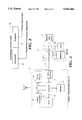
- FIG. 5is a flow chart diagram that shows the steps for a method of processing of the data message by a mobile switching center.
- FIG. 6is a flow chart diagram that shows the steps for a method for initiating the transmission of a data message via the control channel.
- FIG. 7is a block diagram of the preferred embodiment of the page acknowledgment system in its preferred environment of a CMR system.
- FIG. 8is a table that shows the format for the data message that is communicated via the page acknowledgment system.
- FIG. 9is a table that shows the format for the acknowledgment message that is communicated via the page acknowledgment system.
- FIG. 10is a block diagram of another embodiment of the page acknowledgment system.
- FIG. 11is a block diagram of the remote communications device.
- FIG. 12is a flow chart diagram that shows the steps for a method of communicating the acknowledgment message via the page acknowledgment system.
- FIG. 1illustrates the preferred embodiment of a data message system 10 in the preferred environment of a cellular mobile radiotelephone (CMR) system 8.
- CMRcellular mobile radiotelephone
- the data collection system 10supports the collection and communication of data to a central data collection site by reporting systems associated with numerous data sources.
- the data message system 10takes advantage of an existing wide area communications network and avoids the expense of communicating with each remote data site via a dedicated conventional telephone facility or conventional two-way radios.
- CATVcommunity antenna television
- PSVpay-per-view
- the data message system 10adapts the existing environment of a CMR system to communicate data from one or more remote sites to a central location. However, to conserve the use of voice channels of the CMR system for conventional telephone conversations, the data collection system 10 uses the cellular network control channel of the CMR system for data communications. This permits conservation of the valuable frequency spectrum dedicated to the voice channels of the typical CMR system.
- a typical CMR systemincludes a geographic radio service area, such as indicated by the cell 12, of which a plurality of cells are typically provided in a typical cellular service operator's system.
- the cell 12is served by a broadcast antenna 14 to permit communications between cellular mobile radiotelephones operating within the cell 12 and a cell control 16.
- a mobile telephone switching officesuch as the mobile switching center (MSC) 24, can communicate with the cell 12 either by dedicated telephone facilities (not shown) or, more frequently, by a cell-to-mobile switching center data link 22 between the cell control 16 and the MSC 24. At least a portion of the data link 22 is typically supported by a wireless communications link, such as the microwave link 20, located between the cell 12 and the MSC 24.
- the conventional CMR systemcomprises at least one mobile telephone switch coupled to an appropriate array of more or less identically equipped cell sites 12.
- the MSC 24normally couples telephone conversations involving mobile radiotelephones operating in the cell 12 to the public switched telephone network (PSTN) 26 through telephone facilities 28.
- PSTNpublic switched telephone network
- the data collection system 10includes a set of data reporting devices 29, each comprising at least one monitor 32 for collecting data from remote data sources 30 and a cellular communications device 34 for communicating the collected data via a control channel of the CMR system to the MSC 24.
- the monitor 32which is connected to a corresponding remote data source 30 via a signal path 31, obtains and records selected data directed to the operation or performance characteristics of the data source 30.
- the cellular communications device 34which is connected to the corresponding monitor 32 via a signal path 33, prepares a data packet containing the selected data and transmits the packet as a data message.
- the selected datarepresents actual data acquired by the monitor 32 in response to monitoring the operation or performance of the data source 30.
- the selected datacan represent predetermined data or a preprogrammed message that is associated with the detection of a certain event by the monitor 32 for the data source 30.
- the MSC 24receives the data message via a cellular network control channel 38 formed by the combination of the data link 22 and a cellular communications link 36 between the broadcast antenna 14 and the cellular communications device 34.
- This combination of communications linksis collectively referred to as the control channel.
- a cellular network control channel for a conventional CMR systemcomprises two radio channels that are commonly described as a forward control channel (FOCC) and a reverse control channel (RECC).
- the FOCCis used for communications initiated by the MSC to a radiotelephone unit.
- the RECCis used for communications from the radiotelephone to the MSC 24.
- the communications operations of the preferred embodimentalso use this convention for communications between the MSC 24 and the cellular communications device 34.
- control channel 38comprises two separate data communications paths, an FOCC for communications initiated by the MSC 24 and an RECC for communications initiated by the cellular communications devices 34 (or mobile radiotelephones operating within the cell). Accordingly, the cellular communications device 34 transmits data messages via the RECC, whereas the MSC 24 transmits command signals via the FOCC.
- the MSC 24can receive data messages from each of the cellular communication devices 34 operating within the coverage areas of an array of cells for the CMR system 8.
- the data messagescontain selected data rather than the parameters normally contained in an actual radiotelephone control information, the MSC 24 will operate upon the data messages as if they were transmitted by a conventional radiotelephone operating within the cell because the data messages are formatted to appear as a registration signal generated by a radiotelephone unit.
- the data collection system 40which is connected to a memory storage device 44, collects the selected data by storing the received data messages within the memory storage device 44. Similar to the MSC 24, the data collection system 40 also can process the selected data to obtain further information concerning the operation or performance of the data sources 30.
- the data collection system 40sends the data message to a data processing system 46 via a second communications link 48.
- the data processing system 46is typically remotely located from the data collection system 40 and facilitates convenient processing of the selected data at a central site.
- the second communications link 48is typically implemented by a conventional telephone facility, a dedicated data link, or by a wireless communications link.
- a typical application for the data collection system 10is to monitor the loads of an electrical load system and to communicate energy consumption data to a central site for processing.
- the utility industrytypically determines the effectiveness of an electrical load management system for a selected control scenario by collecting or monitoring energy consumption data for certain customers during load management activities. In particular, the utility compares the maximum energy consumed by the selected customers for certain collection periods to the maximum energy that would be consumed by those customers in the absence of any load management activities.
- a utilitytypically uses a load profile recorder located proximate to each customer's electrical load for recording the customer's power consumption during predetermined time intervals. Upon the conclusion of the collection period, the recorded energy consumption data is then forwarded from each load profile recorder to a central data processing site for data translation and evaluation. It is well known to use a conventional telephone system to send energy consumption data recorded by the load profile recorder to the data processing site.
- the monitor 32operates as a load profile recorder to obtain the energy consumption data from the data source 30, in this case an electrical load.
- the cellular communications device 34thereafter transmits a data message containing the energy consumption data to the MSC 24.
- the MSC 24can then forward the data message to the data collection system 40 for processing of the energy consumption data or, in turn, the data collection system 40 sends the data message to the data processing system 46 for processing operations.
- the utilitycan collect energy consumption data from numerous electrical loads to support the utility's evaluation of the effectiveness and cost benefit of its electrical load management program.
- a system for monitoring and communicating data pertinent to the commercial operation of a reporting systemsuch as a soft drink vending machine
- a reporting systemsuch as a soft drink vending machine
- a central data collection sitevia a conventional telephone facility on a nondedicated basis
- Such systemspermit the monitoring of various occurrences within vending machines, such as inventory changes, service calls, cash receipts, demand for certain products, sold-out conditions, and miscellaneous alarm functions.
- the monitor 32monitors the commercial operations of the data source 30, in this case a vending machine, and the cellular communications device 34 transmits a data message containing the operation parameters to the MSC 24. Similar to the utility application, the MSC 24 can then forward the data message to the data collection system 40 for processing of the selected data. Alternatively, the data collection system 40 can respond by sending the data message to the data processing system 46 for processing operations.
- the data collection system 10adapts the existing architecture and communications protocols for a conventional CMR system to supply a novel and economical approach to the communication of data collected from numerous remote sites. It will be understood that the communication of data messages between the MSC 24 and the cellular communications device 34 is primarily based upon conventional techniques and known protocols for CMR system communications. Accordingly, prior to describing the detailed operation of the data collection system 10, it will be useful to review the operation of a typical CMR system.
- a CMR systemis generally characterized by dividing a radio coverage area into smaller coverage areas or "cells" using low power transmitters and coverage-restricted receivers. As will be known to those skilled in the art, the limited coverage area allows the radio channels used in one cell to be reused in another cell. As a mobile radiotelephone within one cell moves across the boundary of the cell and into an adjacent cell, control circuitry associated with the cells detects that the signal strength of the mobile radiotelephone in the just-entered cell is stronger, and communications with the mobile radiotelephone are "handed-off" to the just-entered cell.
- a CMR systemtypically uses a pair of radio frequencies for each radio channel and each cell.
- Each celltypically includes at least one signaling channel, also referred to as a cellular network control channel or an access channel, and several voice channels.
- the control channelis selected or dedicated to receive requests for service from mobiles and portables, to page selected mobiles or portables, and to instruct the mobiles or portables to tune to a predetermined voice channel where a conversation may take place. Accordingly, the control channel is normally responsible for receiving and transmitting data to control the communication actions of the mobile and portable radiotelephones.
- the control channelnormally comprises an FOCC for communications from the MSC to a radiotelephone unit and an RECC for communications from a radiotelephone unit to the MSC.
- the FOCCsupplies a multiplexed data stream of message data words, a busy idle signal, and busy idle bits.
- the busy idle bitsare useful for supplying an indication to monitoring radiotelephones about the current status of the RECC. If the RECC is in use by a radiotelephone unit, then the RECC is considered to be busy and the busy idle bit is set to a binary one value. Alternatively, if the RECC is not in use, then the RECC is considered to be idle and the busy idle bit is set to binary zero value.
- Mobile radiotelephonesmonitor the busy idle bits transmitted by the FOCC and, if the busy idle bit is set to a binary one value, then the mobile radiotelephone delays transmission on the RECC until the busy idle bit is set to a binary zero value.
- a radiotelephonenormally transmits on the control channel during the window of opportunity that is presented by a transition from the busy state to the idle state.
- the busy idle bitsupplies an instantaneous view of the signaling activity on the control channel, and the conventional radiotelephone is responsive to this instant snapshot of control channel activity.
- EIA/TIAElectronic Industries Association/Telecommunications Industry Association
- FCCFederal Communications Commission
- MINMobile Identification Number
- SCMStation Class Mark
- ESNElectronic Serial Number
- the MINis assigned to a particular radio telephone unit by the cellular service provider selected by the subscriber.
- the MINtypically contains information unique to the CMR system operator, for example, the first three digits of the MIN ("XXX”) typically correspond to an area code, the next three digits (“XXX”) typically correspond to a geographic location within the area code; and the final four digits ("XXXX”) identify a particular piece of equipment.
- the ESNis unique to each mobile cellular radiotelephone unit, and comprises a format that allows differentiation as to manufacturer and, in some cases, the model number, date of manufacture, and the like.
- the MSCalso known as a "switch,” makes voice connections between mobile radiotelephones and other telecommunications networks.
- a determinationis typically made whether the radiotelephone is an authorized user or subscriber by looking up the unit's telephone number, serial number, and other information supplied by the radiotelephone to see if there is an entry in the MSC's database corresponding to that particular telephone.
- An optional function of an MSCis to validate that the ESN and MIN received as part of a Call Origination message are valid.
- the received ESNis compared to the MSC's database ESN entry to detect fraud. If these checks succeed, the cellular call is then allowed to proceed.
- the radiotelephonewhen a mobile radiotelephone first powers up or first enters a CMR system when already powered, the unit can identify itself as actively present within the system.
- the radiotelephoneidentifies itself or "registers" through a process known as Autonomous Registration by supplying a data packet similar to that of a Call Origination.
- the Autonomous Registration signalalso referred to as a registration or identification signal, typically comprises data fields for at least a mobile telephone number, i.e., the MIN, and an ESN.
- Autonomous Registrationis simply a set of messages periodically and autonomously sent from the mobile radiotelephone to the serving cell at an interval specified in data parameters previously received from the cell by the cellular unit.
- a subscriber using or attempting to use his or her mobile radiotelephone in a service area outside the home service areais said to be "roaming," and he or she (and the associated mobile radiotelephone unit) is commonly referred to as a "roamer.”
- the radiotelephonewill subsequently receive a message via the control channel of the particular cell in which the telephone then resides. This message will include a request that the subscriber register for operation in the particular cellular system.
- both the mobile telephone number and the serial number for the radiotelephone unitare transmitted as identifying information back to the cell site. The cell forwards this information to a mobile switching center, which quickly ascertains whether the radiotelephone unit is a customer of the local cellular service provider or the customer of another cellular system.
- the mobile switching centerwill send a message packet to the home system for the particular telephone unit.
- This messageindicates that the particular radio telephone unit has registered in another cellular system and requests information about the validity of the number and account information for the radio telephone unit.
- the home systemresponds by transmitting a responsive packet containing the requested information. If valid, the mobile switching center at the foreign cellular system will then add the roamer to its list of registered users and the home cellular system will add the subscriber associated with the radio telephone unit to a list of roamers that are out of the service area and registered in another area.
- the database at the mobile switching center for the home systemwill observe that the unit has moved again and will update its list of where the roaming unit has most recently registered in a database system. In addition, it will send a message to the first foreign system informing it that the roaming unit has now moved on and registered in another system, and that the first foreign system should delete the particular unit from its list of registered roamers. In this manner, the databases at the various mobile switching centers are not cluttered with data identifying previously registered roamers as valid accounts to whom service should be provided, when these roamers may have long since left the area of service.
- the MSC 24in response to the transmission of a data message by a cellular communications device 34, the MSC 24 typically makes a determination whether the cellular communications device 34 that transmitted the data message is an authorized user or subscriber of the services offered by the cellular system 8 or another system.
- the data messagepreferably includes certain information that identifies the cellular communications device 34 as a radiotelephone that normally operates within a certain remote or foreign cellular system. Based upon this information, the MSC 24 decides that the cellular communications device 34 is a roamer because it actually subscribes to the cellular service offered by another cellular system, which, in this case, is the remote cellular system.
- the MSC 24maintains a list or database that identifies the certain information in the data message as belonging to a particular cellular system and, by checking this database, determines whether the cellular communications device 34 is a subscriber or a roamer. Thus, it will be understood that the MSC 24 interprets the data message as a transmission from a roaming mobile radiotelephone operating within the CMR system 8.
- the remote cellular system identified by the data messageis not an actual operating cellular system for supporting telephone conversations, but rather is dedicated to data collection applications and is represented by the data collection system 40.
- the MSC 24forwards the data message to the data collection system 40 via the first communications link 42.
- the data collection system 40responds by sending to the MSC 24 a message which confirms that the roamer associated with the data message is a valid or authorized user of the remote cellular system.
- the cellular communications device 34is thereafter added as a registered radiotelephone to a database of registered roamers at the MSC 24.
- the data collection system 40has now received the data message containing selected data collected from the remote data source 30 and, unlike the MSC 24, recognizes that the data message actually contains the desired data collected from a remote data source 30. Accordingly, the data collection system 40 transmits a message to the MSC 24 that instructs the MSC to delete the cellular communication device 34 from its list of registered roamers. It will be understood that the MSC 24 would normally receive this type of message when a roaming radiotelephone has moved to another cellular system and subsequently registered for operation on that other system. Thus, the database of the MSC 24 is no longer required to maintain the registration information concerning the cellular communications device 34 after transferring the data message to the data collection system 40.
- the MSC 24clears its database of such registration information upon the expiration of a certain time interval.
- the data collections system 40can respond to the data message by transmitting a message which confirms that the roamer is a valid user and further instructs the MSC 24 to delete the registration entry upon the expiration of the certain time interval.
- the MSC 24can automatically delete a registration entry from the MSC database upon expiration of a certain time period without any instruction from the data collection system 40. In this manner, the data collection system 40 is not required to send yet another message to the MSC 24 after the data collection system 40 confirms that the cellular communications device 34 represents a valid user.
- the MSC 24 and the data collection system 40are preferably compatible with the EIA/TIA Interim Standard 41 (IS-41 standard).
- the IS-41 standarddefines a communications protocol for communications between two cellular systems.
- the IS-41 standardallows cellular calls to be handed-off between dissimilar cellular systems, not unlike the way that calls are handed-off between cells of a single CMR system.
- the IS-41 standardpermits call deliveries and a communications exchange for verifying whether a cellular caller is a valid cellular service subscriber.
- the MSC 24hands-off or forwards the data message to the data collection system 40 via the first communications link 42, which is preferably implemented as an IS-41-compatible network.
- the data collection systemsends a user validation message via the link 42 to confirm that the source of the data message, specifically a cellular communications device 34, is a valid cellular source.
- the data collection system 40recognizes that the received data message contains selected data which has been transmitted by a cellular communications device 34. Accordingly, the data collection system 40 processes the received data message and compares the predetermined identifying characteristic in its data message to a list of such characteristics in its database. This database preferably contains an entry of the predetermined identifying characteristic for each of the known cellular communications devices 34 and corresponding data that identifies the associated device as a valid cellular source. Upon obtaining a positive match, the data collection system 40 preferably responds to the received data message by sending to the MSC 24 the verification message. It will be appreciated that the data collection system 40 also can forward to the MSC 24 a message confirming the absence of a valid entry for the cellular communications device 34 in response to a negative match.
- This validation messagecan also include a profile of communications services that are authorized for use by the particular cellular source.
- this user profiletypically defines the operations limitations for the cellular source, including access to long distance services, the capability for the source to only originate (and not receive) calls via the cellular system, etc.
- the user profile informationcan contain an instruction that commands the MSC 24 to delete from its database the registration entry for the particular cellular communications device after the expiration of a certain time period. This allows the MSC 24 to clear from its database entries for cellular communications devices 34 that have communicated their data message via the cellular system 8 by registering with the MSC 24 because such devices no longer require the continued communications support of the MSC 24.
- the data collection system 40can store the selected data supplied by the received data message within the memory storage device 44, can process the selected data and store the resultant data, or can forward the selected data to the data processing system 46 for processing. Prior to sending the selected data to the data processing system 46, the data collection system 40 first converts the data message to an acceptable communications protocol for conveying the data message to the data processing system 46. This step is necessary prior to communication with the data processing system 46 because, unlike the MSC 24 and the data collection system 40, neither the data processing system 46 nor the second communications link 48 are compatible with the IS-41 standard.
- the MSC 24is programmed to treat the cellular communications devices 34 as roamers associated with a foreign cellular system
- the database of the MSC 24also can be programmed to contain entries for the predetermined identifying characteristics of those cellular communications devices 34 operating within the cells of the cellular system 8.
- an MSC 24 containing such database entrieswill identify the transmitting cellular communications device 34 as a "home" unit rather than as a roamer because the MSC database contains an entry that corresponds to the predetermined identifying characteristic supplied by the message.
- the MSC 24registers the transmitting cellular communications device 34 as a home unit of the cellular system 8. This avoids the additional requirement of contacting a foreign cellular system, such as the data collection system 40, to inquire whether this cellular source is a valid user or subscriber of cellular services.
- the MSC 24for this embodiment is adapted to recognize that data messages should still be forwarded to the data collection system 40. Specifically, based upon a portion of the predetermined identifying characteristic that is uniquely associated with the data collection system 40, the MSC 24 locates an entry in its database that commands the switch to send all messages containing such a characteristic to the data collection system 40. Accordingly, the MSC 24 thereafter forwards the data message via the first communications link 42 to the data collection system 40.
- the data collection system 40can be implemented by a computer.
- One embodiment for the data collection system 40is the computer of a service circuit node.
- the cellular system 8is preferably implemented as an AMPS or a DAMPS cellular system. However, it will be appreciated that the cellular system 8 also can be compatible with alternative cellular systems implementing a control channel for mobile to cell communications, including: DCS 1800, GSM, IS 95-CDMA, JTACS, TAGS, ETACS, RC 2000, NMT 450, ESMR, CT-2, WAGS, NMT 900, or other similar wireless systems.
- the CMR system 8includes an array of cells, such as the cell 12, and that a set of reporting systems 29, each formed by the monitor 32 and the cellular communications device 34, are typically located in a cell.
- the monitor 32 and the cellular communication device 34are preferably located proximate to the data source 30 to minimize the lengths of the signal paths 31 and 33.
- the monitor 32 and the cellular communication device 34can be combined within the same housing and this housing can be installed either adjacent to or as an integral part of the data source 30.
- the signal path 31 and the signal path 33preferably form hard-wired connections between the connected devices. Nevertheless, it will be appreciated that the signal paths 31 and 33 also can be implemented as either infrared communications links or wireless communications links.
- a single cellular communications device 34can be connected to multiple monitors 32 to permit the transmission of selected data collected from associated data sources 30 located at a central site.
- a single cellular communications device 34can be mounted at a central location within or along an office building and multiple monitors 32 can be distributed throughout the building to permit the acquisition of data from the associated data sources 30.
- the data collection system 40can be located proximate to or as an integral part of the MSC 24, in which case the first communication link 42 preferably forms a hard-wired connection between the devices. However, the data collection system 40 also can be positioned at a remote site.
- the first communications link 42can be implemented as a wireless communications system, such as a microwave system, or as a dedicated data line, such as a conventional telephone facility.
- the data processing system 46is typically located at another remote site that is typically proximate to the sponsoring party.
- FIG. 2is a table that shows the format for the data message that is communicated by the data message system 10.
- a data record 50 for the data messagecontains both a data field 54 for the selected data acquired from the remote data source 30 and a data field 52 for a predetermined identifying characteristic which uniquely identifies the cellular communications device 34 that initiates the transmission of the data message.
- the format for the data messagepreferably is identical to the message format (or data record) for an identification signal that is transmitted by a cellular radiotelephone when it first identifies itself to a CMR system, such as the CMR system 8.
- the cellular communications device 34By using the data message format associated with a registration signal, the cellular communications device 34 "registers" with the MSC 24 by sending a data message that appears to contain a valid mobile telephone number and an ESN. Although it is not intended for the cellular communications device 34 to place a conventional voiced-based cellular telephone call, the cellular communications device 34 nevertheless registers for operation with the MSC 24, thereby enabling the communication of the selected data from the field.
- the standard message format for a registration signalhas been adapted by the data message to permit the identification of the particular transmitting cellular communications device 34 and the communication of the selected data.
- the data field 52 for the predetermined identifying characteristiccorresponds to at least a portion of a mobile telephone number or MIN assigned to the cellular communications device 34.
- the predetermined identifying characteristicis substituted within the data field normally reserved for the MIN in an identification signal.
- This predetermined identifying characteristiccan belong to a set of unassigned mobile telephone numbers.
- the predetermined identifying characteristic assigned to each cellular communications device 34can be a conventional telephone number or a set of 10 digits.
- the predetermined identifying characteristicpermits the identification of the source of the data by uniquely identifying the cellular communications device 34 associated with the remote data source 30.
- the predetermined identifying characteristicalso supplies information used by the MSC 24 to recognize that the data message containing this predetermined identifying characteristic is associated with the data collection system 40.
- the data field 54 in the data message for remote datacorresponds to the location within the data record of an identification signal for the ESN.
- the ESNis 32 bits long and includes 8 bits for a manufacturer code.
- the selected data within the data field 54comprises a length defined by the remaining 24 bits of the ESN.
- it will not be necessary to manipulate the manufacturer's code segment of the ESNbecause a data message having 24 bits of selected data (and, as required, 8 bits of the manufacturer code segment for a conventional ESN) should be sufficient to supply relevant data.
- EIA/TIA-553defines an extended protocol message that can be adapted to contain the above-described data fields for the predetermined identifying characteristic and the selected data.
- the data messageis formatted to represent an extended protocol message in accordance with EIA/TIA-553.
- This extended protocolextends the signaling capabilities of the interface between the MSC and mobile cellular devices to allow new features and operational capabilities for present and future cellular systems.
- the extended protocol message for the RECCincludes a message header and at least one message data word (up to N message data words).
- the message headerconsists of two words, a header word A and a header word B.
- the header word Aincludes a format having the following fields: field F1 (2 bits set to the binary value 11), which indicates the start of the header; a reserved field RSVD (2 bits set to the binary value 00); a message class field T (1 bit set to the binary value 1); an S field (1 bit set to the binary value 0), which indicates whether the cellular device should send its serial number when it accesses the system; an E field (1 bit set to the binary value 1), which indicates whether the cellular device should send MIN 1 and MIN 2; an extended protocol indicator ER field (1 bit); an SCM field (4 bits); an MIN field (24 bits); and a cyclic redundancy code P (12 bits).
- the header word Bincludes the following fields: field F2 (2 bits set to the binary value 10), which indicates the start of the second header word; a reserved field RSVD (2 bits set to the binary value 00); a message length indicator MSL field (5 bits); a message type indicator MST field (8 bits); an LT field (1 bit), which indicates whether the next access by the cellular device should be the last access try; an extended protocol capability indicator EP field (1 bit set to a binary value 1); a reserved field RSVD (7 bits set to a binary value 0 . . . 0); an MIN 2 field (10 bits); and a cyclic redundancy code P (12 bits).
- the message data wordincludes the following fields: field F3 (2 bits set to the binary value 01), which designates the first to last N-1 message data words, or field F4 (2 bits set to the binary value 00), which designates the last message data word; the message data (34 bits); and a cyclic redundancy code P (12 bits).
- a mobile switching centernormally is programmed or otherwise adapted to conduct a predetermined operation upon an extended protocol message or to implement a certain action in response to the reception of a extended protocol message.
- the MSC 24is preferably programmed to forward to the data collection system 40 each data message that is formatted as an extended protocol message. This communication of the extended protocol message does not require the MSC 24 or the data collection system 40 to be implemented as an IS-41-compatible communications system.
- the first communications link 42 for this embodimentcan be implemented as a dedicated data link or a wireless communications link rather than as an IS-41-compatible communications network.
- FIG. 3is a block diagram that illustrates the components of the reporting system 29, namely the monitor 32 and the cellular communications device 34.
- the monitor 32includes a recorder 60, a memory 62, and one or more sensors 64.
- the recorder 60which is connected to the data source 30 via the signal path 31, uses the sensors 64 to detect certain operating or performance characteristics of the data source 30.
- the detected characteristicsrepresent selected data that are preferably stored within the memory storage device 62.
- the memory 62is preferably random access memory (RAM). However, it will be understood that the memory 62 also can be implemented by other types of mass data storage devices, including a computer hard disk drive or an optical disk drive.
- the signal path 31represents one or more signal channels for transferring the selected data to the recorder 60 and, furthermore, that the recorder 60 can be implemented as either a single or multi-channel recording device. Each signal channel normally would be associated with a different operating or performance characteristic for the data source 30.
- the recorder 60records selected data from the data source 30 for a predetermined time period.
- a clock 66 connected to the recorder 60supplies timing data to the recorder 60, thereby enabling the recorder 60 to add a time tag to the selected data.
- the time tagindicates the relative time for the start of each predetermined time period of recording operations. Assuming that the predetermined time period is a known value, the addition of the time tag data permits the calculation of the start and completion times for each data reporting operation. Correlation of the data collection time to the selected data is desirable for certain processing operations.
- the clock 66can be implemented as a conventional counter supplied by a hardware device or as a software routine executed by a microprocessor.
- the cellular communications device 34includes at least a data receiver 70, a cellular transmitter 72, and a controller 74.
- the data receiver 70which is connected to the recorder 60 via the signal path 33, receives the selected data obtained from the data source 30 by the monitor 32.
- the controller 74which is connected to the data receiver 70 and the cellular transmitter 72, controls the respective operations of the data receiver 70 and the cellular transmitter 72.
- the controller 74is preferably a microprocessor-based control system that can be programmed to conduct control operations in a manner known to the art.
- the controller 74prepares a data packet containing the predetermined identifying characteristic associated with the cellular transmitter 72 and the selected data collected from the data source 30.
- the cellular transmitter 72responds to the data packet by transmitting a corresponding data message via the control channel 38 of the CMR system 8. Specifically, the cellular transmitter 72 uses the RECC of the control channel 38 to send data messages to the MSC 24.
- the cellular transmitter 72can be implemented as a conventional transmitter for a radiotelephone unit, the preferred cellular transmitter 72 uses only the data radio channels of the CMR system 8 for transmission of data messages.
- the cellular communications device 34further includes a memory storage device 76 connected via a bi-directional data path to the controller 74.
- the selected data received by the data receiver 70can be stored in the memory storage device 76 prior to the transmission of a data message by the cellular transmitter 72.
- the memory storage device 76is shown as a separate memory from the memory storage device 62, it will be appreciated that the memory storage devices 62 and 76 can be implemented as a single memory which is accessible by both the recorder 60 and the controller 74.
- the cellular communications device 34To receive communications from the MSC 24 via the control channel 38, the cellular communications device 34 also includes a cellular receiver 78.
- the cellular receiver 78which is connected to the controller 74, can be implemented as the cellular receiver for a conventional radiotelephone. However, similar to the cellular transmitter 72, the preferred cellular receiver 78 operates to receive information primarily via the data radio channels rather than the voice radio channels of the CMR system.
- the FOCC of the cellular network control channelcarries a stream of busy idle bits to indicate the status of the RECC of the cellular network control channel.
- the RECCis busy if the busy idle bit is set to a binary one value.
- the cellular transmitter 72preferably transmits the data message during those periods when the channel is available or is likely to be available. Accordingly, the cellular receiver 78 monitors the FOCC of the control channel 38 to enable a determination of the amount of activity on the RECC for the monitored cell.
- the cellular communications device 34can determine the level of control channel activity during that time period. If the level of control channel activity falls below a certain threshold associated with light or no activity on the control channel, then the controller 74 supplies the data packet to the cellular transmitter 72. In response, the cellular transmitter 72 initiates a data message transmission to the MSC 24 via the RECC of the control channel 38.
- the cellular communications device 34preferably monitors the busy idle bits carried by the FOCC of the control channel 38 for sequential, predetermined time periods.
- the cellular communications device 34calculates and stores (1) a running average of the "highest" count of busy idle bits set to the binary one value per each monitoring time period, and (2) a last "n" count of busy idle bits set to the binary one value per monitoring time period.
- a newly acquired count of busy idle bits set to the binary one value per time periodis averaged with a stored average of busy idle bits set to the binary one value if the count for the immediately preceding interval is higher than a value of one standard deviation lower than the stored average.
- the cellular communications device 34Prior to transmitting a data message via the control channel 38, the cellular communications device 34 will average the stored last "n" counts of busy idle bits set to the binary one value per time period and compare that computed "n” average to the stored running average. If the computed "n” average drops below the stored running average, then the cellular communications device 34 outputs the data message. However, if the computed "n” average exceeds the stored running average, then the cellular communications device 34 will delay the transmission. In contrast to conventional radiotelephone units, which are responsive to an instantaneous view of activity on the control channel, it will be appreciated that the above-described transmission queuing process is a heuristic method based upon a deterministic analysis of the stream of busy idle bits.
- the cellular transmitter 78transmits the data message only when the control channel is available for clear use by the cellular communications device 34.
- This form of data queuingminimizes the possibility that the operation of numerous cellular communications devices 34 within the cell 12 will interfere with normal telephone conversations involving the operating radiotelephones within the cell. Nevertheless, it will be appreciated that the cellular transmitter 78 also can transmit the data message without first checking the availability of the control channel 38.
- the cellular communications device 34can be programmed to transmit the data message during a certain time interval, such as during the early morning hours between midnight and 6 AM, when control signal traffic is normally at a minimal level.
- the cellular communications device 34includes a clock 82 connected to the controller 74.
- the clock 82outputs a clock signal in response to expiration of a time interval.
- the controller 74initiates a data message transmission by the cellular transmitter 72. In this manner, selected data is transmitted during a known time interval from one of the reporting devices within the cell 12 to a central location.
- the clock 82preferably outputs the clock signal during the time period when use of the control channel 38 is at a reduced level, thereby minimizing the possibility that the cellular communications device 34 will interfere with the normal communications operations of the CMR system 8.
- the time intervalis preferably selected with advance knowledge of the reduced activity periods for conventional telephone conversation traffic on the CMR system 8 to ensure that data message transmissions by the various cellular communications devices 34 in the cell 12 are conducted on a noninterference basis with voice call processing messages transmitted to and from the radiotelephones operating in the cell.
- the clock 82can be implemented as either a hardware counter or as a software counter implemented by coded instructions executed by the controller 74.
- a data transmission by the cellular communications device 34also can be initiated in response to a status signal output via the signal path 33 by the monitor 32.
- This status signalcauses the cellular communications device 34 to transmit the stored selected data via the RECC of the control channel 38.
- the monitor 32typically outputs the status signal in response to the completion of a data recording event.
- the monitor 32can output the status signal in response to an alarm event, such as the detection of a maintenance service requirement.
- the monitor 32can output the status signal in response to detection of possible tampering of the utility's load control device.
- the process of outputting a clock signal or a status signal to initiate a data message transmission by the cellular communications device 34is similar to an Autonomous Registration operation that is conducted by certain known radiotelephone units.
- the radiotelephoneautomatically identifies itself to the cellular system by initiating its own registration operation.
- the cellular communications device 34responds to the clock signal or the status signal by sending a data message having a message format that is representative of the data record for a registration signal of a radiotelephone unit.
- the MSC 24receives the data message via the control channel 38 and subsequently operates upon the data message as if it were a registration signal transmitted by a conventional radiotelephone unit.
- the time interval for the clock 82is preferably selected to minimize any interference from data message transmissions, it is still possible that the cellular network control channel 38 may be busy when the clock 82 outputs the clock signal to initiate a transmission by the cellular transmitter 72.
- the data message transmissionis delayed until the cellular communications device 34 detects a level of activity on the control channel 38 that is less than a certain threshold for a predetermined time period. Although this delays a data message transmission that normally would have taken place in direct response to the clock signal, the delay allows the cellular communications device 34 to transmit the data message during an interval when the control channel 38 is not busy.
- the controller 74responds to the clock signal output by the clock 82 by detecting the busy idle bits set to a binary one value, as carried by the FOCC and received via the cellular receiver 78, and calculating both the running average and the "n" average.
- This running averageis stored within the memory storage device 76.
- the controller 74will supply a data packet containing the selected data to the cellular transmitter 72 only when the computed "n" average drops below the stored running average. It will be appreciated that this process of queuing the transmission of data messages typically requires the storage of the selected data within the memory 76 prior to initiating the data message transmissions.
- a cellular network control channelsuch as the control channel 38
- the receiver 78is also useful for receiving communications from the MSC 24 via the FOCC of the control channel 38.
- the MSC 24can output command signals via the control channel 38 to initiate certain operations or to control certain functions of one or more of the cellular communication devices 34 within the cell 12.
- the cellular communications device 34is preferably programmed to respond to a command signal by conducting a particular operation or by controlling a certain function associated with the command signal.
- the command signalstypically include address data and each cellular communications device 34 only responds to a command signal containing its predetermined address data. This allows the MSC 24 to communicate with one or more of certain selected communications devices 34. By proper use of the addressing operation, it is possible for the MSC 24 to remotely control the operations or functions of a subset of the cellular communications devices 34 that is selected from the overall group of devices 34 within the cell 12.
- the address data of the command signalis preferably a 10 digit number that represents a conventional telephone number. At least a portion of this telephone number is assigned to a corresponding cellular communications device 34. The remaining portion (if available for use) of the 10-digit telephone number can represent a command for a particular operation or function. In this manner, a cellular communications device 34 can be programmed to respond only to a command signal containing its address data and to conduct the particular operation or function identified by the address data.
- the MSC 24can remotely control various operations of the cellular communications devices 34 or can remotely define various programmable operating parameters of the devices 34.
- the cellular communications device 34"registers" with the MSC 24 by transmitting a data message to the MSC 24.
- this command signalis similar to a conventional Locate Request signal generated by a CMR system, such as the AT&T Autoplex System, and requests registration of a selected radiotelephone unit.
- a selected cellular communications device 34can be polled at any time by the MSC 24 to initiate the transmission of a data message containing the desired selected data.
- the time interval for the clock 82is modified or otherwise replaced with a substitute time period.
- the cellular communications device 34also can instruct the monitor 32 to initiate a recording of data from the remote data source 30 in response to yet another command signal.
- the controller 74responds to the detection of the command signal by the cellular receiver 78 and outputs an instruction signal to the recorder 60 to prompt the data reporting operation.
- FIG. 4shows the preferred steps of a method for communicating data collected from remote data sources via a cellular control channel.
- the methodstarts at the start block 200.
- the operation of one or more remote data sources 30is monitored, typically for a predetermined time period.
- selected data directed to the operation or performance characteristics of the remote data source 30are collected and stored.
- a data packet containing the selected data and the predetermined identifying characteristicis prepared in the step 206.
- the data message corresponding to the data packetis transmitted to the MSC 24 via the control channel 38 of the CMR system 8.
- the above-described stepsare preferably implemented by one or more software routines that are executed by the reporting system 29 formed by the monitor 32 and the cellular communications device 34.
- the programnext branches to block A (FIG. 5).
- the MSC 24determines whether an incoming registration signal has been transmitted by a roamer or by a home unit based upon the information contained in the registration signal, which is, in this case, the data message.
- FIG. 5illustrates the preferred steps taken by the MSC 24 to determine whether the data message has been transmitted by a roamer or by a home unit and the resulting actions taken by the MSC 24 based upon this initial determination.
- a registration signalsuch as the data message
- the database operations conducted by the MSC 24begin at step 210 of branch A.
- a registration signalsuch as the data message, is received via the control channel 38 at the MSC 24.
- the received MINis a MIN associated with a home unit having an entry in the database of the MSC 24.
- the "YES" branchis followed to block 216.
- the home unitregisters with the MSC 24.
- the conventional radiotelephones operating within the cell 12represent subscribers to the cellular services offered by the CMR system 8 and, accordingly, those radiotelephones will be identified as home units.
- the transmissions by the cellular communications devices 34 operating within the cell 12are preferably designed to appear as transmissions from roamers associated with a foreign or remote CMR system, such as the data collection system 40.
- step 218the MSC 24 determines that the source of the registration signal is a roamer. Specifically, for the data message, the MSC 24 makes this determination according to the predetermined identifying characteristic, which is located in a data field that corresponds to the MIN. At least a portion of the predetermined identifying characteristic identifies the data collection system 40 as the "home" service provider for the cellular communications device 34. Thus, the MSC 24 determines that the data message has been transmitted by a roamer associated with a foreign CMR system, specifically the data collection system 40.
- the database maintained by the MSC 24is checked to determine whether the roamer's MIN is present in the database as a result of an earlier registration with the CMR system 8. As explained in more detail below, the MSC 24 normally will not locate the predetermined identifying characteristic of the data message within this database because the data message has been transmitted by a cellular communications device 34 rather than by a conventional radiotelephone unit that is associated with the cellular system 8. If this inquiry is negative, the "NO" branch is followed to block 222.
- the MSC 24forwards certain identification information to the foreign CMR system associated with the roamer. For the data message, the MSC 24 transmits the data message, including the predetermined identifying characteristic and the selected data, via the first communications link 42 to the data collection system 40. At this point, the data collection system 40 recognizes that the data message contains the desired selected data and typically stores the selected data within the memory storage device 44 to facilitate subsequent uses of the selected data.
- the steps 222 and 224are jumped by following the "YES" branch to decision block 228.
- Information concerning the roameri.e., the cellular communications device 34
- the database at the MSC 24is subsequently added, at least temporarily, to the database at the MSC 24 during the step 224 in response to a validation message transmitted by the data collection system 40.
- an inquiryis conducted to determine if the MSC 24 has received an instruction from the data collection system 40 which requests the deletion of the roamer information from the MSC database. If the response is positive, the "YES" branch is followed to step 230 and the MSC 24 deletes the entry from the database. In this manner, the database is not cluttered with information that is no longer relevant to the operations of the MSC 24. In contrast, if the response is negative, then the "NO" branch is followed back to the step 228.
- FIG. 5The steps shown is FIG. 5 are preferably implemented by one or more software routines that reside on and are executed by the MSC 24.
- the software development techniques necessary to code this process and to create the necessary software routinesare known by those skilled in the art.
- FIG. 6is a flow chart diagram that shows the steps for a method for initiating the transmission of a data message via a cellar network control channel of a cellular system when the control channel is clear for use.
- the methodis started at the start block 240.
- an inquiryis made whether a certain time interval has expired. If the time period has not expired, the "NO" branch is followed to the start block 240. In contrast, if the time period has expired, then the "YES" branch is followed to the block 244.
- a clock signalis output upon the expiration of the certain time interval.
- a data packetis prepared in step 246 to permit the transmission of a data message containing the predetermined identifying characteristic and the selected data.
- the cellular communications device 34is ready to transmit the data message if a data channel of the cellular network control channel is available on a noninterference basis.
- step 248the cellular communications device 34 monitors the stream of busy idle bits carried by the FOCC of the control channel 38 and thereafter calculates the average for the last "n" busy idle bits having a binary one value per time interval.
- decision block 250an inquiry is conducted to determine whether the computed "n" average is less than the stored running average of the highest count of busy idle bits having a binary one value per time interval. If the response to this inquiry is negative, the control channel 38 is busy and, accordingly, transmission of the data message is delayed by following the "NO" branch to the step 248 and the sequence of monitoring the busy idle bits and calculating averages continues. In contrast, if the response is positive, then the "YES" branch is followed to step 252 and the data message is transmitted via the RECC of the control channel 38 to the MSC 24.
- FIG. 6The steps shown is FIG. 6 are preferably implemented by one or more software routines that reside on and are executed by the cellular communications device 34.
- the software development techniques necessary to code this process and to create the necessary software routinesare known by those skilled in the art.
- a paging acknowledgment system 10'operates within the environment of a CMR system 8' for communicating acknowledgment messages in response to reception of paging messages. This allows a paging party that uses the communications services offered by the system 10' to receive some form of an acknowledgment that a paged party has actually received the paging message.
- the paging acknowledgment system 10'takes advantage of the installed equipment offered by a conventional CMR system, such as the CMR system 8, to supply either a local area or wide area communications system for communicating acknowledgment messages. Because the acknowledgment messages contain data-based information rather than voice-based information, the system 10' uses only the cellular network control channel of a CMR system for communicating the acknowledgment messages. By avoiding any use of the valuable voice channels of a CMR system, the system 10' conserves the use of the voice channels for conventional telephone conversations by users of cellular radiotelephones. Accordingly, the system 10' permits the expanded use of available resources offered by existing or adapted equipment for a CMR system, while minimizing any interference to conventional voice-based applications, namely telephone conversations.
- the paging acknowledgment systemincludes a communications system 149 comprising at least one paging terminal 150 and a data collection system 40', one or more remote communications devices 152, and at least one MSC 24' associated with the CMR system 8'.
- the communications system 149responds to a paging message from a paging party by preparing a data message that corresponds to the paging message.
- a particular acknowledgment codewhich is assigned by the communications system 149 to the data message, is stored to support a subsequent determination of whether the data message has been properly acknowledged by one of the remote communications devices 152.
- the communications system 149thereafter transmits the data message via a communications path 156 to a selected remote communications device 152.
- a selected remote communications unit 152receives the data message and thereafter prepares an acknowledgment message containing the acknowledgment code taken from the data message.
- the selected remote communications device 152then transmits the acknowledgment message to the MSC 24' via the cellular network control channel 38.
- the MSC 24'recognizes that the source of the acknowledgment message is associated with the communications system 149 and forwards the acknowledgment message to the communications system 149 via a first communications link 42'.
- the communications system 149processes the acknowledgment message and determines whether the acknowledgment message corresponds to a particular one of the data messages. This determination is made by comparing the acknowledgment code in the acknowledgment message to the stored acknowledgment codes associated with data messages. If a match is made, then the acknowledgment can be stored for later use or supplied to the paging party.
- a party desiring to contact another party at a remote siteforwards a paging message via a communications network 151 for eventual transmission by the paging terminal 150.
- the paging terminal 150transmits a data message, which corresponds to the paging message, via an antenna 154.
- the combination of the paging terminal 150 and the antenna 154preferably operates as a wireless transmission system having the capability of broadcasting data messages over a known geographical area.
- a remote communications device 152operating within the geographical coverage area, is responsive to a data message containing its particular address.
- the remote communications device 152transmits an acknowledgment message via a cellular network of the CMR system 8', namely the control channel 38' and the MSC 24'. As described below, the reception of the acknowledgment message by the MSC 24' enables the process for verifying the reception of the data message.
- the paging terminal 150receives a paging message via the communications network 151, such as the preferred public switched telephone network (PSTN).
- PSTNpublic switched telephone network
- the communications network 151can be implemented as other known communications systems, including a data network, such as a value added network (VAN) (not shown), or a dedicated data line (not shown).
- VANvalue added network
- the paging terminal 150is adapted to handle the special requirements for an acknowledgment system and responds to the paging message by preparing a corresponding data message.
- the data messageincludes the following information: (1) an address that uniquely identifies the intended receiving device, specifically a selected remote communication device 152, (2) an acknowledgment code that uniquely identifies the particular data message and the corresponding paging message, and (3) paging data associated with the paging message.
- the format of the data messagewill be described in more detail below with respect to FIG. 8.
- the paging partytypically supplies the information associated with the address for the selected remote communications device 152 and the paging data for communication to the user of the selected device 152.
- the paging terminal 150is adapted to supply the acknowledgment code for use with the data message and preferably stores or archives the acknowledgment code to permit later comparisons to an acknowledgment code returned in acknowledgment messages from the remote communications devices 152, as described below.
- Each data messageis assigned a unique acknowledgment code to support the comparison of data messages to a particular acknowledgment message.
- the paging terminal 150thereafter transmits the data message to complete the communication of the paging message to the intended paged party.
- the paging terminal 150For local area communication of a paging message, the paging terminal 150 transmits the corresponding data message for direct reception by a selected remote communications device 152 that is known to normally operate within the geographic coverage area of the paging terminal 150. However, if the remote communications device 152 normally operates outside of the geographical coverage area of the paging terminal 150, then the terminal 150 forwards the data message to another paging terminal via a national paging network (not shown) for transmission of the data message within the appropriate geographical area.
- a national paging networknot shown
- the paging terminal 150communicates with the remote communications devices 152 operating within its geographical coverage area via a communications path 156, which is preferably implemented as a wireless communications system, such as a microwave or radio frequency (RF) radio link.
- a communications path 156also can be implemented by a wired communications system, including a dedicated data line or a conventional telephone facility.
- the paging terminal 150transmits the data message via the antenna 154.
- a remote communications device 152responds to a data message containing its particular address by supplying the paging data associated with the paging message to the user of the device 152.
- the preferred remote communications device 152outputs an alert to the user to indicate the reception of a data message and thereafter presents in a conventional manner the paging data to the user.
- the alertcan be a visual, audible, or tactile signal and the presentation of the paging data can be conducted in an audible or textual (or graphical) format.
- the remote communications device 152further responds to the data message by sending via the CMR system 8' an acknowledgment message that includes the acknowledgment code of the data message.
- the acknowledgment codepermits a subsequent correlation between the outgoing data message (and corresponding paging message) and the incoming acknowledgment message.
- the acknowledgment messagecontains information in a data-type format to permit communication of this information via the control channel 38'
- the acknowledgment messageis formatted to appear as a registration signal that is transmitted by a conventional radiotelephone unit when the unit first identifies itself to the CMR system.
- the remote communications device 152sends the acknowledgment message to the cell control 16 in the cell 12 via a cellular communications link 36.
- the cell control 16forwards the acknowledgment message to the MSC 24' via the data link 22.
- the control channel 38which is formed by the data link 22 and the cellular communications link 36, permits the communication of control signals between each remote communications device 152 within the cell 12 and the MSC 24'.
- the MSC 24'receives the acknowledgment message via the control channel 38 and, based upon certain information supplied in the acknowledgment message, determines that the message appears to have been transmitted by a roaming radiotelephone unit. Without any recognition that the acknowledgment message was actually transmitted by a remote communications device 152, the MSC 24' treats the acknowledgment message as if the message had been transmitted by a roamer. Accordingly, the MSC 24' forwards via a first communications link 42' the acknowledgment message to a data collection system 40'. In turn, the data collection system 40' recognizes that the acknowledgment message contains an acknowledgment code and sends the code via the communications link 174 to the paging terminal 150 for comparison with the stored acknowledgment codes assigned to the outgoing data messages. A successful match confirms the reception of a data message corresponding to a particular paging message.
- FIG. 8is a table that shows the format for a data message that is transmitted by the paging terminal 150 in response to a paging message.
- a data record 160 for the data messagecontains the address data, which uniquely identifies a particular remote communications device 152, the acknowledgment code, which uniquely identifies the data message and the corresponding paging message, and paging data intended for communication to the subscriber that operates the selected remote communications device 152.
- the address data within the field 162preferably is associated with a particular CAP code or personal identification number (PIN) that has been assigned to the selected remote communications unit 152.
- the address data, acknowledgment code, and paging dataare contained within separate data fields, respectively an address data field 162, an acknowledgment code field 164, an the paging data field 166.
- the data fields 162, 164, and 166are preferably separated by one or more identifying characters or character strings to separate the information within those fields and to enable an accurate reading of such information.
- a paging messageis typically initiated when the paging party contacts the paging terminal 150 via the communications path 151, which is shown in FIG. 7 as a PSTN.
- the paging partythen has the opportunity to supply the desired paging data, such a return telephone number, to the paging terminal 150 in a conventional manner, either by speaking to an operator, who will supply the paging data in the proper format to the paging terminal 150, or by inputting the paging data via telephone equipment.
- the paging messagealso can be initiated in response to a message transmitted via an electronic mail system.
- a portion of the data messageshould be returned to the paging terminal 150 via an acknowledgment message forwarded by the CMR system 8'.
- the format for the characters of the acknowledgment codeis preferably compatible with the overall message format for the acknowledgment message.
- the data record for the acknowledgment messageis shown in FIG. 9. Referring now to FIGS. 7 and 9, a data record 168 for the acknowledgment message contains separate fields for both user-entered data and the acknowledgment code.
- the field 170 for the user-entered data and the field 172 for the acknowledgment codeare separated by a selected character set to identify the completion of the character string for the operation data and the start of the character string for the acknowledgment code.
- One or more characterscan be appended to the end of the data record to indicate the end of the data message.
- the data record 168 for the acknowledgment messageis preferably identical to the message format for a registration signal transmitted by a radiotelephone when it first identifies itself to a CMR system, such as the CMR system 8'.
- the data field 172 for the acknowledgment codecorresponds to the location in a registration signal for at least a portion of a mobile telephone number or MIN.
- the acknowledgment codepreferably belongs to a set of conventional telephone numbers, a set of 10 digit numbers, or a set of unassigned mobile telephone numbers.
- the acknowledgment codealso contains information that enables the MSC 24' to determine that the acknowledgment message has been transmitted by a source that is associated with the data collection system 40'.
- the subscriber that uses the remote communications device 152has an option of supplying a response to a received data message.
- This responsewhich is referred to as operation data
- operation datais supplied by the user in a conventional manner by inputting the operation data via a keypad located along the remote communications device 152.
- a response to the received data messagecan be automatically supplied by the remote communications unit 152 without any action by the subscriber.
- the operation datatypically comprises textual characters or binary data that are inserted within the data field 170 of the acknowledgment message data record 168.
- the data field 170 for the operation datacorresponds to the location within a data record of a registration signal for an ESN.
- ESNelectronic network
- the data field 170 for the operation datacorresponds to the location within a data record of a registration signal for an ESN.
- the data field 170 for the operation datacorresponds to the location within a data record of a registration signal for an ESN.
- the data field 170 for the operation datacorresponds to the location within a data record of a registration signal for an ESN.
- the data field 170 for the operation datacorresponds to the location within a data record of a registration signal for an ESN.
- the format for the acknowledgment messagealso can be modified to allow the insertion of both the acknowledgment code and the optional operation data within a data field that corresponds to the location for the ESN in a registration signal.
- each data messageis assigned an identifying acknowledgment code and each remote communications device 152 is assigned a unique mobile telephone number that serves to identify the transmitting cellular source.
- the remote communications device 152outputs an acknowledgment message which includes a data field containing its particular mobile telephone number and a data field containing both the acknowledgment code and the optional operation data.
- the acknowledgment codeis preferably separated from the operation data within the same data field by one or more separating characters.
- This acknowledgment messageis formatted to represent a registration signal and the data fields correspond to locations for a MIN and an ESN in a conventional registration signal.
- the mobile telephone number in this acknowledgment messageserves to identify the transmitting cellular source, specifically the particular remote communications device 152, and the acknowledgment code operates to identify the corresponding data message (and paging message).
- the remote communications device 152in response to a data message, the remote communications device 152 either transmits the data message in an automated mode without subscriber intervention or in a manual mode controlled by the subscriber.
- the remote communications device 152By transmitting an acknowledgment message having a message format associated with a registration signal, the remote communications device 152 "registers" with the MSC 24' because the acknowledgment message appears to contain both a valid mobile telephone number and an ESN.
- the remote communications device 152is merely attempting to send an acknowledgment as a data-type signal via the control channel instead of placing a conventional voice-based telephone call, the device 152 nevertheless registers for operation with the MSC 24' to enable communication of the acknowledgment code via the CMR system 8'.
- the MSC 24'makes a determination whether the device that transmitted the signal is an authorized user or subscriber of the services offered by the CMR system 8'. This determination is based upon the acknowledgment code within the data record 172, which corresponds to the MIN information for a registration signal. At least a portion of the acknowledgment code indicates that the selected remote communications device 152 is associated with another "remote" cellular system. Based upon this information, the MSC 24' checks its database and determines that the remote communications device 152 subscribes to a remote cellular system, namely the data collection system 40'.
- the MSC 24'determines that the source of the acknowledgment message should be treated as a roamer Thus, it will be understood that the MSC 24' interprets the acknowledgment message as a transmission from a roaming mobile radiotelephone operating within the CMR system 8'.
- the remote cellular systemwhich is identified by a portion of the acknowledgment code, is not an actual operating cellular system for supporting telephone conversations, but rather is dedicated to acknowledgment-based applications and is represented by the data collection system 40'.
- the MSC 24'forwards the acknowledgment message to the data collection system 40' via a first communications link 42'.
- the data collection system 40'responds by sending to the MSC 24' a validation message which confirms that the source of the acknowledgment message is associated with the data collection system 40' and that the MSC 24' should accept communications from that source.
- the remote communications device 152is added as a registered radiotelephone to a database of registered roamers at the MSC 24', thereby completing the registration of the acknowledgment message source at the MSC 24'.
- the data collection system 40'subsequently transmits a message to the MSC 24' via the link 42' that instructs the MSC to delete the remote communications device 152 from its list of registered roamers.
- This entryis deleted from the MSC database because it is no longer necessary to maintain the registration information concerning the remote communications device 152 after the transfer of the acknowledgment message to the data collection system 40'.
- the database entry for the registered remote communications device 152is deleted by the MSC 24' upon the expiration of a time interval.
- the data collection system 40'recognizes that the acknowledgment message contains certain data which confirms that a selected remote communications device 152 has received a data message and has forwarded a response, specifically the acknowledgment message containing the acknowledgment code and the operation data. Accordingly, the data collection system 40' sends the acknowledgment code and the operation data via a communications link 174 to the paging terminal 150 to permit the paging terminal to update its acknowledgment records.
- the paging terminal 150compares the acknowledgment code supplied by the data collection system 40' to its list of acknowledgment codes assigned to data messages (and corresponding paging messages). A successful match indicates that the intended recipient of the paging message, specifically a selected remote communications device 152, has received the data message and has forwarded an acknowledgment message to confirm the data message reception. Based upon this comparison, the paging terminal 150 stores acknowledgment information in a database or in a memory storage device to archive this acknowledgment of the paging message for access by the paging party. The paging terminal 150 also stores the operation data, if any, to permit access by the paging party to the response from the user of the selected remote communications device 152.
- the data collection system 40' and the paging terminal 150can be installed as separate systems located at different locations or as fully integrated equipment at the same site.
- the remote communications unit 152also can supply paging information to equipment adapted to receive such paging information.
- the transmission of the data message by the paging terminal 150is useful for initiating an operation by the adapted equipment, such as the recording of data from a data source.
- the adapted equipmentalso can supply operation data to the remote communications unit 152 for transmission via the cellular system 8' to a central collection site. If the equipment is primarily used for recording data, then the acknowledgment message transmitted by the remote communications unit 152 contains operation data including recorded data.
- the remote communications unit 152can be connected to the adapted equipment via a hard-wired connection or a wireless link to permit the exchange of data messages and operation data.
- communications between the data collection system 40' and the MSC 24'are preferably compatible with the IS-41 standard. Accordingly, the MSC 24' can hand-off or forward the data message to the data collection system 40' via the first communications link 42', which is preferably implemented as an IS-41 network.
- the MSC 24'can hand-off or forward the data message to the data collection system 40' via the first communications link 42', which is preferably implemented as an IS-41 network.
- other devices and protocolsare useful for implementing communications with the data collection system 40', including the Motorola DMX protocol and other vendor proprietary protocols.
- a communications system 149'comprises a data collection system 40" and a paging terminal 150'.
- the data collection system 40"accepts the paging messages via the communications network 151, such as the PSTN, rather than the paging terminal 150'.
- the data collection system 40"assigns an unique identifier to the paging message, specifically an acknowledgment code, and prepares a data packet for transmission to the paging terminal 150'.
- the data packetincludes the following information: (1) the address that uniquely identifies the intended receiving device, (2) the acknowledgment code, and (3) the paging data.
- the paging terminal 150'receives the data packet via a communications link 176 and, in response, outputs a data message corresponding to the data packet for reception by the selected remote communications device 152.
- the data collection system 40"also stores the acknowledgment code corresponding to the data packet (and the paging message) to permit a comparison of the stored acknowledgment code to an acknowledgment code in the acknowledgment messages forwarded by a remote communications unit 152 via the CMR system 8'.
- the data collection system 40" shown in FIG. 10conducts the acknowledgment operations (but not the paging operations) that are performed by the paging terminal 150 for the embodiment 10' shown in FIG. 7.
- the communications between the paging terminal and the remote communications device 152, as well as the communications between the MSC 24' and the data collection system 40",are identical to the operations described for the embodiment shown in FIG. 7. Still referring to FIG. 10, the paging terminal 150' broadcasts the data message in a conventional manner via the antenna 154 for reception by the selected remote communications device 152. In response, the selected remote communications device 152 registers for operation with the MSC 24' by outputting the acknowledgment message. Based upon at least a portion of the acknowledgment code in the acknowledgment message, the MSC 24' recognizes that the selected remote communications device 152 is associated with another cellular system, in this case the data collection system 40". Accordingly, the MSC 24' forwards the acknowledgment message to the data collection system 40" via the first communications link 42'.
- the data collection system 40"By comparing the acknowledgment code in the acknowledgment message to the stored acknowledgment code assigned to the corresponding data message, the data collection system 40" recognizes that the data message was received by the selected remote communications device 152. Based upon this acknowledgment, the data collection system 40" deletes the assigned acknowledgment code from its database of transmitted data packets for which it is awaiting acknowledgment and thereafter takes whatever action is appropriate to provide an acknowledgment to the party who originated the page request. There is no need to forward the acknowledgment message to the paging terminal 150' because the paging terminal is implemented as a conventional paging system that does not perform any acknowledgment operations.
- the data collection system 40" and the paging terminal 150'can be separate systems located at different locations or can be installed at the same site as fully integrated equipment.
- FIG. 11is a block diagram that illustrates the components of the remote communications device 152.
- the remote communications device 152includes a paging device 178 and a cellular device 179.
- the paging device 178 and the cellular device 179are packaged within the same housing to facilitate convenient use of the device 152 by the typical mobile subscriber.
- a batteryis a preferred power source for the device 152 in view of the intended portable use of the device.
- the paging device 178includes a paging receiver 180 that receives the data message from the paging terminal 150 via the communications link (FIG. 7) and, in turn, stores the acknowledgment code and the paging data within a memory storage device 184. In response to the data message, the paging receiver 180 outputs an alert to the user to advise of the reception of the data message and thereafter supplies the paging data to the user in a known manner, typically via a display (not shown) or as an audible message output via a speaker (not shown).
- the paging receiver 180also responds to the data message by outputting the acknowledgment code to the cellular transmitter 182 via a data channel 186 connected between the two devices. If the user responds to the data message by inputting operation data, the operation data is normally stored within the memory storage device 184 until it is transferred to the cellular transmitter 182 via the data channel 186.
- the paging receiver 180is a conventional pager that has been adapted to receive information associated with the acknowledgment process, namely the acknowledgment code.
- the paging receiver 180must distinguish between the data fields in the data record 160 to insure that the paging receiver 180 properly recognizes and processes the information contained in the data message.
- the cellular device 179includes a cellular transmitter 182 that receives the acknowledgment code and the operation data over the data channel 186 and stores this information within a memory storage device 190.
- the cellular transmitter 182reads the acknowledgment code and the operation data from the memory storage device 190, prepares the acknowledgment message by placing this information within the data fields 170 and 172, and thereafter transmits the acknowledgment message via the control channel 38.
- the acknowledgment message transmissions by the cellular transmitter 182are compatible with conventional cellular standards and protocols for the transfer of data signals (not voice signals) over a control channel.
- the cellular transmitter 182can be implemented as a transmitter for a conventional radiotelephone unit, with the exception that the transmitter is adapted to accept the acknowledgment code and the operation data via the data channel 186. Indeed, by transmitting the acknowledgment message in response to the data message, the remote communications device 152 conducts an operation that is similar to an autonomous registration operation performed by a standard radiotelephone.
- the cellular transmitter 182only requires the capability to transmit on the data channels of a cellular network control channel, such as the control channel 38, because the system 10 does not use the voice channels for forwarding acknowledgment messages via the CMR system 8'. Accordingly, the cellular transmitter 182 should draw less power than a conventional radiotelephone that operates on both the voice and data channels of the a cellular network control channel. In addition, the cellular transmitter 182 typically draws power only during data transmission intervals, thereby conserving the preferred power source, a battery. A typical acknowledgment message transmission occurs as a burst of data in the form of a data packet, thereby further reducing power consumption.
- Power conservationis significant to the convenient use of the remote communications device 152 because the device 152 is primarily intended for use by a mobile subscriber who does not have regular access to another type of power source. It will be appreciated that an alternative power source for the cellular transmitter 182 is a capacitor capable of storing sufficient energy to transmit the data bursts.
- the cellular device 152To receive communications from the MSC 24' via the control channel 38, the cellular device 152 also includes a cellular receiver 192 connected to the cellular transmitter 182.
- the cellular receiver 192can be implemented as the cellular receiver for a conventional radiotelephone unit. However, similar to the cellular transmitter 182, the preferred cellular receiver 192 operates to receive information primarily via the data radio channels rather than the voice radio channels of the CMR system 8'.
- the remote communications device 152Similar to the cellular communications device 34 (FIG. 3), the remote communications device 152 also can employ a form of acknowledgment message queuing that delays the transmission of the acknowledgment message until the control channel 38 is available for use on a noninterference basis.
- the remote communications unit 152preferably monitors the busy idle bits on the control channel 38 to determine the level of control signal activity prior to transmission of acknowledgment messages. This minimizes the impact of transmission by one or more of the remote communications devices 152 within the cell 12 upon the normal control signals supplied via the control channel 38 to radiotelephone units operating within the cell.
- the cellular receiver 192monitors the busy idle bits carried by the FOCC of the control channel 38 for sequential, predetermined time periods.
- the remote communications unit 152calculates and stores both a running average of the highest count of busy idle bits per time period and the last "n" count of busy idle bits per time period. To calculate the running average, a newly acquired count of busy idles bits per time period is averaged with a stored average if the count for the busy idle bits for the immediately preceding interval is higher than a value of one standard deviation lower than the stored average.
- the remote communications unit 152Prior to transmitting an acknowledgment message via the control channel 38', the remote communications unit 152 will average the stored last "n" counts of busy idle bits per time period and compare that computed "n” average to the stored running average. If the computed "n” average drops below the stored running average, then the cellular transmitter 182 outputs the acknowledgment message via the RECC of the control channel 38'. However, if the computed "n” average exceeds the stored running average, then the cellular transmitter 182 will delay the transmission.
- the acknowledgment message transmissionpreferably occurs only when the control channel 38 is available for clear use by the remote communications device 152. It will be understood that this message cueing technique may delay the transmission of the acknowledgment message if the control channel 38 is busy.
- FIG. 12is a flow chart diagram that shows the preferred steps for a method for communicating an acknowledgment message via a cellular network control channel of a CMR system in response to a paging message.
- the methodstarts at start block 260 and, at step 262, a paging message is received via the communications network 151.
- a data message corresponding to the paging messageis prepared in step 264.
- an acknowledgment codeis added to the address data and the page data previously supplied by the paging message.
- the acknowledgment code associated with the data message (and the paging message)is stored for use during a subsequent acknowledgment operation.
- the data messageis then transmitted by a paging terminal, such as the paging terminal 150' in the step 266.
- step 268the data message is received by a selected remote communications unit 152 having the particular address contained in the data message.
- an acknowledgment messageis prepared during step 270.
- the acknowledgment messageincludes the acknowledgment code taken from the data message and any operation data input by the subscriber.
- step 272the acknowledgment message is transmitted to the MSC 24' via the control channel 38.
- the MSC 24'receives the acknowledgment message at step 274 and, based upon at least a portion of the acknowledgment code in the acknowledgment message, forwards the acknowledgment message to the data collection system 40" in step 276.
- an inquiryis conducted to determine whether the acknowledgment code in the acknowledgment message is identical to a previously stored acknowledgment code associated with a particular data message (see step 265). If the answer is positive, then the "YES" branch is followed to step 280, in which an acknowledgment confirming the receipt of the paging message is supplied to the paging party. In contrast, if the response is negative, then the "NO" branch is followed to step 282. In step 282, the paging party is advised that an acknowledgment has not been received in response to the paging message.
Landscapes
- Engineering & Computer Science (AREA)
- Computer Networks & Wireless Communication (AREA)
- Signal Processing (AREA)
- Mobile Radio Communication Systems (AREA)
- Telephonic Communication Services (AREA)
Abstract
Description
Claims (77)
Priority Applications (17)
| Application Number | Priority Date | Filing Date | Title |
|---|---|---|---|
| US08/212,039US5546444A (en) | 1994-03-11 | 1994-03-11 | Methods and apparatus for communicating data via a cellular network control channel |
| BR9408553ABR9408553A (en) | 1994-03-11 | 1994-08-04 | Processes and devices for data communication via cellular network control channel |
| CA002185230ACA2185230C (en) | 1994-03-11 | 1994-08-04 | Methods and apparatus for communicating data via a cellular network control channel |
| PCT/US1994/008862WO1995024791A1 (en) | 1994-03-11 | 1994-08-04 | Methods and apparatus for communicating data via a cellular network control channel |
| CNA2003101186245ACN1549567A (en) | 1994-03-11 | 1994-08-04 | Methods and apparatus for acknowledging a paging message via a cellular network control channel |
| CNB941950808ACN1152550C (en) | 1994-03-11 | 1994-08-04 | Method and apparatus for transmitting data over a control channel of a cellular network |
| NZ271792ANZ271792A (en) | 1994-03-11 | 1994-08-04 | Data communication; method and apparatus using a cellular network control channel of a radio telephone system, data represented as an identification signal of a cellular subscriber |
| AU75555/94AAU682208B2 (en) | 1994-03-11 | 1994-08-04 | Methods and apparatus for communicating data via a cellular network control channel |
| EP94925749AEP0753230A4 (en) | 1994-03-11 | 1994-08-04 | Methods and apparatus for communicating data via a cellular network control channel |
| JP7523428AJPH10500262A (en) | 1994-03-11 | 1994-08-04 | Method and apparatus for communicating data over a cellular network control channel |
| KR1019960705067AKR100368291B1 (en) | 1994-03-11 | 1994-08-04 | Data communication method and device through cellular network control channel |
| US08/331,794US5526401A (en) | 1994-03-11 | 1994-10-31 | Methods and apparatus for acknowledging a paging message via a cellular network control channel |
| US08/622,438US5794144A (en) | 1994-03-11 | 1996-03-25 | Methods and apparatus for communicating data via a cellular mobile radiotelephone system |
| US08/969,146US6154648A (en) | 1994-03-11 | 1997-11-12 | Methods and apparatus for communicating data via a cellular mobile radiotelephone system |
| US09/013,558US6125275A (en) | 1994-03-11 | 1998-01-26 | Cellular communications device for communicating data via a cellular network control channel |
| US09/160,512US6108537A (en) | 1991-01-28 | 1998-09-24 | Method and system for performing a predetermined operation related to a predetermined class of cellular sources |
| JP2001342407AJP3600570B2 (en) | 1994-03-11 | 2001-11-07 | Paging receipt notification system and method |
Applications Claiming Priority (1)
| Application Number | Priority Date | Filing Date | Title |
|---|---|---|---|
| US08/212,039US5546444A (en) | 1994-03-11 | 1994-03-11 | Methods and apparatus for communicating data via a cellular network control channel |
Related Parent Applications (1)
| Application Number | Title | Priority Date | Filing Date |
|---|---|---|---|
| US77522497AContinuation-In-Part | 1991-01-28 | 1997-06-16 |
Related Child Applications (2)
| Application Number | Title | Priority Date | Filing Date |
|---|---|---|---|
| US08/331,794DivisionUS5526401A (en) | 1994-03-11 | 1994-10-31 | Methods and apparatus for acknowledging a paging message via a cellular network control channel |
| US08/622,438Continuation-In-PartUS5794144A (en) | 1991-01-28 | 1996-03-25 | Methods and apparatus for communicating data via a cellular mobile radiotelephone system |
Publications (1)
| Publication Number | Publication Date |
|---|---|
| US5546444Atrue US5546444A (en) | 1996-08-13 |
Family
ID=22789306
Family Applications (2)
| Application Number | Title | Priority Date | Filing Date |
|---|---|---|---|
| US08/212,039Expired - LifetimeUS5546444A (en) | 1991-01-28 | 1994-03-11 | Methods and apparatus for communicating data via a cellular network control channel |
| US08/331,794Expired - LifetimeUS5526401A (en) | 1994-03-11 | 1994-10-31 | Methods and apparatus for acknowledging a paging message via a cellular network control channel |
Family Applications After (1)
| Application Number | Title | Priority Date | Filing Date |
|---|---|---|---|
| US08/331,794Expired - LifetimeUS5526401A (en) | 1994-03-11 | 1994-10-31 | Methods and apparatus for acknowledging a paging message via a cellular network control channel |
Country Status (10)
| Country | Link |
|---|---|
| US (2) | US5546444A (en) |
| EP (1) | EP0753230A4 (en) |
| JP (2) | JPH10500262A (en) |
| KR (1) | KR100368291B1 (en) |
| CN (2) | CN1549567A (en) |
| AU (1) | AU682208B2 (en) |
| BR (1) | BR9408553A (en) |
| CA (1) | CA2185230C (en) |
| NZ (1) | NZ271792A (en) |
| WO (1) | WO1995024791A1 (en) |
Cited By (138)
| Publication number | Priority date | Publication date | Assignee | Title |
|---|---|---|---|---|
| WO1997019547A1 (en)* | 1995-11-22 | 1997-05-29 | Aeris Communications, Inc. | Method for two-way communication and processing of control channel application specific data |
| US5675371A (en)* | 1995-10-27 | 1997-10-07 | Location Science Corporation | Apparatus for monitoring cable television system remote equipment performance and status using a cell modem |
| US5684859A (en)* | 1995-05-01 | 1997-11-04 | Motorola, Inc. | Method and apparatus for downloading location specific information to selective call receivers |
| WO1998019447A1 (en)* | 1996-10-28 | 1998-05-07 | Tracy Corporation Ii | Telecommunications interface and associated method for collecting and transmitting data |
| EP0847163A1 (en)* | 1996-11-29 | 1998-06-10 | Electrowatt Technology Innovation AG | Arrangement for a remote testable and/or controllable system |
| EP0847162A1 (en) | 1996-11-29 | 1998-06-10 | Landis & Gyr Technology Innovation AG | Interface unit using interleaving for transmitting digital data over a cellular communications network |
| US5771455A (en) | 1992-01-27 | 1998-06-23 | Highwaymaster Communications, Inc. | Data messaging in a communications network using a feature request |
| US5787149A (en)* | 1995-11-16 | 1998-07-28 | Equitrac Corporation | Method and apparatus for managing remotely located document producing machines by using cellular radios |
| US5794144A (en)* | 1994-03-11 | 1998-08-11 | Bellsouth Corporation | Methods and apparatus for communicating data via a cellular mobile radiotelephone system |
| WO1998026522A3 (en)* | 1996-12-12 | 1998-11-19 | Gte Airfone Inc | Method and apparatus for updating a mobile unit |
| US5842210A (en)* | 1996-10-30 | 1998-11-24 | Motorola, Inc. | Method and apparatus for selectively retrieving data from a database in a data communication system |
| US5845210A (en)* | 1996-08-15 | 1998-12-01 | Ericsson, Inc. | Method and apparatus for supporting data transmission over analog and digital cellular telephone air interfaces |
| US5845203A (en)* | 1996-01-25 | 1998-12-01 | Aertis Cormmunications | Remote access application messaging wireless method |
| US5873043A (en)* | 1996-12-18 | 1999-02-16 | Cellemetry Llc | System for communicating messages via a forward overhead control channel |
| US5901142A (en)* | 1996-09-18 | 1999-05-04 | Motorola, Inc. | Method and apparatus for providing packet data communications to a communication unit in a radio communication system |
| US5914672A (en)* | 1997-06-13 | 1999-06-22 | Whisper Communications Incorporated | System for field installation of a remote meter interface |
| US5937355A (en)* | 1995-12-07 | 1999-08-10 | Telefonaktiebolaget Lm Ericsson (Publ) | Emergency call handling in a cellular telecommunication system |
| US5940740A (en)* | 1996-10-25 | 1999-08-17 | At&T Wireless Services, Inc. | Method and apparatus for message transmission verification |
| WO1999030213A3 (en)* | 1997-12-09 | 1999-08-26 | Bellsouth Corp | System and method for automatically setting a remote timepiece with the correct time |
| WO1999031892A3 (en)* | 1997-12-15 | 1999-08-26 | Alcatel Usa Inc | System for forwarding and logging a digital message from a telecommunications device |
| US5999680A (en)* | 1998-06-29 | 1999-12-07 | Lamah; Ahmad | Telecommunications method for using incomplete call time |
| US5999808A (en)* | 1995-12-12 | 1999-12-07 | Aeris Communications, Inc. | Wireless gaming method |
| US6014557A (en)* | 1996-03-14 | 2000-01-11 | Bellsouth Intellectual Property Corporation | Apparatus and methods for providing wireless system fraud and visibility data |
| GB2308272B (en)* | 1995-12-12 | 2000-01-19 | Europlex Res Ltd | A communication system and method for alarm signals |
| US6018657A (en)* | 1997-05-05 | 2000-01-25 | Highwaymaster Communications, Inc. | System and method for communicating a message using a cellular telephone network |
| US6044265A (en)* | 1995-06-05 | 2000-03-28 | Bellsouth Corporation | Methods and apparatus for cellular set programming |
| US6058299A (en)* | 1997-11-07 | 2000-05-02 | Lyseng; Merlin | Remote telecommunications assembly |
| US6085099A (en)* | 1994-06-20 | 2000-07-04 | Generaldirektion Ptt | Message transmission system |
| US6085087A (en)* | 1995-08-29 | 2000-07-04 | Kabushiki Kaisha Kenwood | Roaming control method for digital mobile telephone |
| WO2000056098A1 (en)* | 1999-03-17 | 2000-09-21 | Telephia, Inc. | System and method for gathering data from wireless communications networks |
| US6144859A (en)* | 1993-08-27 | 2000-11-07 | Aeris Communications, Inc. | Wireless cellular communicator system and apparatus |
| US6147601A (en)* | 1999-01-09 | 2000-11-14 | Heat - Timer Corp. | Electronic message delivery system utilizable in the monitoring of remote equipment and method of same |
| US6150955A (en)* | 1996-10-28 | 2000-11-21 | Tracy Corporation Ii | Apparatus and method for transmitting data via a digital control channel of a digital wireless network |
| EP0878923A3 (en)* | 1997-05-05 | 2000-11-22 | Northrop Grumman Corporation | Half-duplex communication system for telemetry modems |
| US6160477A (en)* | 1999-01-09 | 2000-12-12 | Heat-Timer Corp. | Electronic message delivery system utilizable in the monitoring of remote equipment and method of same |
| US6163704A (en)* | 1996-11-15 | 2000-12-19 | Telefonaktiebolaget Lm Ericsson (Publ) | Delivery of subscriber digital data messages in a dual mode cellular telephone network |
| US6167261A (en)* | 1997-02-27 | 2000-12-26 | At&T Wireless Svcs. Inc. | Wireless communication service management |
| US6169895B1 (en)* | 1996-12-17 | 2001-01-02 | At&T Wireless Svcs. Inc. | Landline-supported private base station for collecting data and switchable into a cellular network |
| US6185198B1 (en)* | 1996-03-20 | 2001-02-06 | Aeris Communications, Inc. | Time division multiple access downlink personal communications system voice and data debit billing method |
| US6211782B1 (en) | 1999-01-09 | 2001-04-03 | Heat-Timer Corporation | Electronic message delivery system utilizable in the monitoring of remote equipment and method of same |
| US6230009B1 (en)* | 1996-12-27 | 2001-05-08 | At&T Wireless Services, Inc. | Method and apparatus for alerting a station in one network of a requested communication from a second network |
| AU733176B2 (en)* | 1996-07-10 | 2001-05-10 | Aeris Communications, Inc. | Variable burst remote access application messaging method and apparatus |
| US6269088B1 (en)* | 1995-08-10 | 2001-07-31 | Hitachi, Ltd. | CDMA mobile communication system and communication method |
| US6278936B1 (en) | 1993-05-18 | 2001-08-21 | Global Research Systems, Inc. | System and method for an advance notification system for monitoring and reporting proximity of a vehicle |
| US6285868B1 (en) | 1993-08-27 | 2001-09-04 | Aeris Communications, Inc. | Wireless communications application specific enabling method and apparatus |
| US6295449B1 (en) | 1992-01-27 | 2001-09-25 | @Track Communications, Inc. | Data messaging in a communications network using a feature request |
| US6297768B1 (en) | 1999-02-25 | 2001-10-02 | Lunareye, Inc. | Triggerable remote controller |
| US6298231B1 (en) | 1998-09-29 | 2001-10-02 | Ready Com, Inc. | Methods, systems, and devices for transmitting messages to wireless devices |
| US6311056B1 (en)* | 1998-05-21 | 2001-10-30 | Cellemetry Llc | Method and system for expanding the data capacity of a cellular network control channel |
| US6311060B1 (en)* | 1998-05-21 | 2001-10-30 | Cellemetry Llc | Method and system for registering the location of a mobile cellular communications device |
| US6313760B1 (en) | 1993-05-18 | 2001-11-06 | Global Research Systems, Inc. | Advance notification system and method utilizing a distinctive telephone ring |
| US6317060B1 (en) | 1999-03-01 | 2001-11-13 | Global Research Systems, Inc. | Base station system and method for monitoring travel of mobile vehicles and communicating notification messages |
| US6333975B1 (en) | 1998-03-03 | 2001-12-25 | Itron, Inc. | Method and system for reading intelligent utility meters |
| US6363323B1 (en) | 1993-05-18 | 2002-03-26 | Global Research Systems, Inc. | Apparatus and method for monitoring travel of a mobile vehicle |
| US6380860B1 (en) | 1999-12-14 | 2002-04-30 | Joseph R. Goetz | Portable wireless cellular fire alarm system apparatus and method |
| US6381454B1 (en)* | 1995-10-10 | 2002-04-30 | Qualcomm Incorporated | Method and system for over-the-air (OTA) service programming |
| US6411891B1 (en) | 1997-03-10 | 2002-06-25 | Global Research Systems, Inc. | Advance notification system and method utilizing user-definable notification time periods |
| US6411802B1 (en) | 1999-03-15 | 2002-06-25 | Bellsouth Intellectual Property Management Corporation | Wireless backup telephone device |
| US6415207B1 (en) | 1999-03-01 | 2002-07-02 | Global Research Systems, Inc. | System and method for automatically providing vehicle status information |
| US6437691B1 (en) | 1999-01-09 | 2002-08-20 | Heat-Timer Corporation | Electronic message delivery system utilizable in the monitoring of remote equipment and method of same |
| WO2002051173A3 (en)* | 2000-12-19 | 2002-09-12 | Gatco | System and method for communicating data messages from a cell phone terminal, such as a geographical location |
| US6462644B1 (en) | 1998-11-19 | 2002-10-08 | The Coca-Cola Company | Network of vending machines connected interactively to data-base building host |
| US6484035B2 (en) | 1998-12-07 | 2002-11-19 | Lunareye, Inc. | Apparatus and method for triggerable location reporting |
| US6501950B1 (en) | 1996-03-14 | 2002-12-31 | Bellsouth Intellectual Property Corporation | Systems and methods for monitoring data signals on a communications network |
| US6516189B1 (en) | 1999-03-17 | 2003-02-04 | Telephia, Inc. | System and method for gathering data from wireless communications networks |
| US20030050038A1 (en)* | 2001-08-17 | 2003-03-13 | Luther Haave | Method and system for asset tracking |
| US6567661B2 (en)* | 2000-03-07 | 2003-05-20 | Hewlett-Packard Company | Distributed telemetry method and system |
| US6570865B2 (en) | 1995-08-10 | 2003-05-27 | Hitachi, Ltd. | CDMA mobile communications system and communication method |
| US6603974B1 (en) | 1999-03-03 | 2003-08-05 | Lucent Technologies Inc. | Method for transferring data |
| US6615045B1 (en) | 1999-03-03 | 2003-09-02 | Lucent Technologies Inc. | Method for transferring data upon request using permanent identifier |
| US6618394B1 (en)* | 1998-07-22 | 2003-09-09 | General Electric Company | Methods and apparatus for economical utilization of communication networks |
| US6625460B1 (en) | 1999-12-21 | 2003-09-23 | Nokia Corporation | Unified messaging protocol using SMS |
| US20030193413A1 (en)* | 1993-05-18 | 2003-10-16 | Jones M. Kelly | Business methods for notification systems |
| US20030208419A1 (en)* | 2000-05-22 | 2003-11-06 | Bunn Arthur H | System, method and apparatus for monitoring and billing food preparation equipment and product |
| US20040015305A1 (en)* | 2000-09-12 | 2004-01-22 | Bunn Arthur H | Machine performance monitoring system and billing method |
| US6700507B2 (en) | 1993-05-18 | 2004-03-02 | Arrivalstar, Inc. | Advance notification system and method utilizing vehicle signaling |
| US6704563B1 (en) | 1998-08-11 | 2004-03-09 | Boston Communications Group, Inc. | Systems and methods for prerating costs for a communication event |
| US20040063446A1 (en)* | 2002-06-18 | 2004-04-01 | Kennett Murray Valpy | Communication apparatus and methods |
| US6718177B1 (en) | 1999-09-20 | 2004-04-06 | Cellemetry, Llc | System for communicating messages via a forward overhead control channel for a programmable logic control device |
| US20040093375A1 (en)* | 2001-03-28 | 2004-05-13 | Mason Terrence I | Method and a system of remotely controlling data transfer via a data transfer network |
| US6738647B1 (en)* | 1999-04-23 | 2004-05-18 | Numerex Corporation | Method and system for expanding the data payload of data messages transported via a cellular network control channel |
| US20040095237A1 (en)* | 1999-01-09 | 2004-05-20 | Chen Kimball C. | Electronic message delivery system utilizable in the monitoring and control of remote equipment and method of same |
| US6741927B2 (en) | 1993-05-18 | 2004-05-25 | Arrivalstar, Inc. | User-definable communications methods and systems |
| US6748320B2 (en) | 1993-05-18 | 2004-06-08 | Arrivalstar, Inc. | Advance notification systems and methods utilizing a computer network |
| US6748227B1 (en)* | 1999-03-03 | 2004-06-08 | Lucent Technologies Inc. | Method for transferring data using permanent identifier including routing information |
| US6810261B1 (en) | 1999-03-03 | 2004-10-26 | Lucent Technologies Inc. | Method for transferring data using expanded permanent identifier |
| US20050025173A1 (en)* | 2003-07-30 | 2005-02-03 | Fischer Michael Andrew | Signaling extended functionality and management information in a network |
| US20050026637A1 (en)* | 2003-07-30 | 2005-02-03 | Fischer Michael Andrew | Intelligent downstream traffic delivery to multi-protocol stations |
| US6882843B1 (en)* | 2000-09-14 | 2005-04-19 | Cellemetry, Llc | Multiple wireless data transport transceiver system |
| US6892074B2 (en)* | 1997-08-28 | 2005-05-10 | Nokia Mobile Phones Limited | Selective message service to primary and secondary mobile stations |
| US6895240B2 (en) | 1998-07-13 | 2005-05-17 | Openwave Systems Inc. | Method and architecture for managing a fleet of mobile stations over wireless data networks |
| US6900737B1 (en) | 1997-02-12 | 2005-05-31 | Elster Electricity, Llc | Remote access to electronic meters using the short message service |
| US20050182599A1 (en)* | 2000-09-12 | 2005-08-18 | Knepler John T. | Remote beverage equipment monitoring and control system and method |
| EP1575251A1 (en)* | 2004-03-10 | 2005-09-14 | Alcatel | Interception module and monitoring centre for ISDN |
| US6952645B1 (en) | 1997-03-10 | 2005-10-04 | Arrivalstar, Inc. | System and method for activation of an advance notification system for monitoring and reporting status of vehicle travel |
| US6975998B1 (en) | 2000-03-01 | 2005-12-13 | Arrivalstar, Inc. | Package delivery notification system and method |
| AU2001257054B2 (en)* | 2000-04-14 | 2005-12-22 | Numerex Corporation | Method and system for expanding the data payload of data messages transported via a cellular network control channel |
| US20060034268A1 (en)* | 2004-07-30 | 2006-02-16 | Seong-Hwan Kim | Network-based data transport architecture |
| US20060099941A1 (en)* | 2004-10-22 | 2006-05-11 | Kim Dae S | Methods and apparatus for providing application-specific messaging over a global system for mobile wireless communication system |
| US20060105752A1 (en)* | 2004-10-21 | 2006-05-18 | Samsung Electronics Co., Ltd. | Apparatus and method for processing short messages in a terminal |
| US7064681B2 (en) | 2003-05-28 | 2006-06-20 | Legalview Assets, Limited | Response systems and methods for notification systems |
| US20060268832A1 (en)* | 2005-05-26 | 2006-11-30 | Cisco Technology, Inc. | Transporting synchronization channel information across a packet network |
| US20060276162A1 (en)* | 2005-06-03 | 2006-12-07 | Omega Patents, L.L.C. | Vehicle security system receiving acknowledgment of transmitted vehicle security message and related methods |
| US7149514B1 (en) | 1997-07-30 | 2006-12-12 | Bellsouth Intellectual Property Corp. | Cellular docking station |
| US7187928B1 (en) | 1998-11-24 | 2007-03-06 | Boston Communications Group, Inc. | Call delivery systems for roaming prepaid subscribers |
| US7191058B2 (en) | 1993-05-18 | 2007-03-13 | Melvino Technologies, Limited | Notification systems and methods enabling user entry of notification trigger information based upon monitored mobile vehicle location |
| US7194243B2 (en) | 2004-04-02 | 2007-03-20 | Maryland Semiconductor Inc. | DC offset and 1/f noise compensation of a direct conversion receiver |
| US7194083B1 (en) | 2002-07-15 | 2007-03-20 | Bellsouth Intellectual Property Corporation | System and method for interfacing plain old telephone system (POTS) devices with cellular networks |
| US7221950B2 (en) | 2001-12-26 | 2007-05-22 | Bellsouth Intellectual Property Corp. | Auto sensing home base station for mobile telephone with remote answering capabilities |
| US7228129B1 (en) | 2001-03-20 | 2007-06-05 | Logical Concepts, Inc. | Expert system for monitoring, recording and controlling remote equipment that minimizes wireless telephone airtime |
| US7233802B2 (en) | 1999-10-29 | 2007-06-19 | Cellemetry, Llc | Interconnect system and method for multiple protocol short message services |
| US7245928B2 (en) | 2000-10-27 | 2007-07-17 | Cellemetry, Llc | Method and system for improved short message services |
| US7272494B2 (en) | 2002-03-28 | 2007-09-18 | Numerex Investment Corp. | Communications device for conveying geographic location information over capacity constrained wireless systems |
| US20070244614A1 (en)* | 1997-08-26 | 2007-10-18 | Paxgrid Telemetric Systems, Inc. | Automotive telemetry protocol |
| CN101107868A (en)* | 2004-10-22 | 2008-01-16 | 艾里斯通讯公司 | Methods and apparatus for providing application-specific message transfer in GSM system |
| US7323970B1 (en) | 2004-01-21 | 2008-01-29 | Numerex Corporation | Method and system for remote interaction with a vehicle via wireless communication |
| US20080238711A1 (en)* | 2007-04-02 | 2008-10-02 | Robert Kent Payne | Automated meter reader direct mount endpoint module |
| US7561069B2 (en) | 2003-11-12 | 2009-07-14 | Legalview Assets, Limited | Notification systems and methods enabling a response to change particulars of delivery or pickup |
| US20090216490A1 (en)* | 2000-09-12 | 2009-08-27 | Bunn-O-Matic Corporation | Remote beverage equipment monitoring and control system and method |
| US7639157B1 (en) | 1998-03-24 | 2009-12-29 | At&T Intellectual Property, I,L.P. | Wireless telemetry methods and systems for communicating with or controlling intelligent devices |
| US7680471B2 (en) | 2006-05-17 | 2010-03-16 | Numerex Corp. | System and method for prolonging wireless data product's life |
| US7783508B2 (en) | 1999-09-20 | 2010-08-24 | Numerex Corp. | Method and system for refining vending operations based on wireless data |
| US8000682B2 (en) | 2002-07-15 | 2011-08-16 | At&T Intellectual Property I, L.P. | Apparatus and method for restricting access to data |
| US20110231546A1 (en)* | 1997-08-26 | 2011-09-22 | Nathanson Martin D | Automotive telemetry protocol |
| US8243908B2 (en) | 2002-07-15 | 2012-08-14 | At&T Intellectual Property I, Lp | Systems and methods for restricting the use and movement of telephony devices |
| US8249570B2 (en) | 1997-07-30 | 2012-08-21 | At&T Intellectual Property I, L.P. | Apparatus, method, and computer-readable medium for interfacing devices with communications networks |
| US8265605B2 (en) | 2007-02-06 | 2012-09-11 | Numerex Corp. | Service escrowed transportable wireless event reporting system |
| US8275371B2 (en) | 2002-07-15 | 2012-09-25 | At&T Intellectual Property I, L.P. | Apparatus and method for providing communications and connection-oriented services to devices |
| US8416804B2 (en) | 2002-07-15 | 2013-04-09 | At&T Intellectual Property I, L.P. | Apparatus and method for providing a user interface for facilitating communications between devices |
| US8526466B2 (en) | 2002-07-15 | 2013-09-03 | At&T Intellectual Property I, L.P. | Apparatus and method for prioritizing communications between devices |
| US8543098B2 (en) | 2002-07-15 | 2013-09-24 | At&T Intellectual Property I, L.P. | Apparatus and method for securely providing communications between devices and networks |
| US8554187B2 (en) | 2002-07-15 | 2013-10-08 | At&T Intellectual Property I, L.P. | Apparatus and method for routing communications between networks and devices |
| US9331892B2 (en) | 2009-03-09 | 2016-05-03 | The Nielsen Company (Us), Llc | System and method for automatic sub-panel creation and management |
| US9419721B2 (en) | 2013-03-15 | 2016-08-16 | Lawrence Livermore National Security, Llc | Wide bandgap matrix switcher, amplifier and oscillator |
| US9438939B2 (en) | 2006-03-27 | 2016-09-06 | The Nielsen Company (Us), Llc | Methods and systems to meter media content presented on a wireless communication device |
| US9992729B2 (en) | 2012-10-22 | 2018-06-05 | The Nielsen Company (Us), Llc | Systems and methods for wirelessly modifying detection characteristics of portable devices |
| US10187767B2 (en) | 2016-07-01 | 2019-01-22 | Paxgrid Cdn Inc. | System for authenticating and authorizing access to and accounting for wireless access vehicular environment consumption by client devices |
| US10841769B2 (en) | 2008-10-28 | 2020-11-17 | Koninklijke Kpn N.V. | Telecommunications network and method of transferring user data in signalling messages from a communication unit to a data processing centre |
Families Citing this family (64)
| Publication number | Priority date | Publication date | Assignee | Title |
|---|---|---|---|---|
| US5889474A (en)* | 1992-05-18 | 1999-03-30 | Aeris Communications, Inc. | Method and apparatus for transmitting subject status information over a wireless communications network |
| US6009309A (en)* | 1993-05-04 | 1999-12-28 | Motorola, Inc. | Method of operation a combination radiotelephone and paging device and method of operation |
| US20030098802A1 (en)* | 1999-03-01 | 2003-05-29 | Jones Martin Kelly | Base station apparatus and method for monitoring travel of a mobile vehicle |
| US5588009A (en)* | 1994-02-03 | 1996-12-24 | Will; Craig A. | Personal paging, communications, and locating system |
| US5734963A (en) | 1995-06-06 | 1998-03-31 | Flash Comm, Inc. | Remote initiated messaging apparatus and method in a two way wireless data communications network |
| US5765112A (en) | 1995-06-06 | 1998-06-09 | Flash Comm. Inc. | Low cost wide area network for data communication using outbound message specifying inbound message time and frequency |
| CA2222691A1 (en) | 1995-06-06 | 1996-12-12 | Flash Comm, Inc. | Determining propagating and clear frequency in wireless data communications network |
| US6711418B1 (en)* | 1995-10-13 | 2004-03-23 | General Wireless Communications Inc. | Wireless personal mobile data terminal receiving a wide-area broadcast and capable of two-way communication in a local area |
| US5797097A (en)* | 1995-11-02 | 1998-08-18 | Bellsouth Corporation | Method and apparatus for identifying the location of a roaming pager |
| US5740540A (en)* | 1995-11-06 | 1998-04-14 | Mototola, Inc. | Method for telephone number notification and storage in a portable radio |
| US5839054A (en)* | 1996-01-02 | 1998-11-17 | Brother International Corporation | Automatic registration paging system |
| US6088431A (en)* | 1996-03-20 | 2000-07-11 | Aeris Communications, Inc. | Method for transmitting voice or data in a wireless network depending on billing account status |
| US5797103A (en)* | 1996-06-14 | 1998-08-18 | Motorola, Inc. | Method and apparatus for informing a remote unit of a feature-originated call |
| US5796728A (en)* | 1996-06-25 | 1998-08-18 | Ericsson Inc. | Communication system and method for modifying a remote radio using an internet address |
| CA2259347A1 (en)* | 1996-06-28 | 1998-01-08 | Harris Corporation | A multiple use wireless communication system and method |
| US5887255A (en)* | 1996-06-28 | 1999-03-23 | Marris Corporation | Multiple use wireless communications system and method |
| US5918158A (en)* | 1996-07-24 | 1999-06-29 | Lucent Technologies Inc. | Two-way wireless messaging system |
| US5924032A (en)* | 1996-09-24 | 1999-07-13 | Nokia Mobile Phones Limited | Mobile telephone having an improved probability of receiving an incoming call |
| US5930771A (en)* | 1996-12-20 | 1999-07-27 | Stapp; Dennis Stephen | Inventory control and remote monitoring apparatus and method for coin-operable vending machines |
| US5883886A (en)* | 1997-01-03 | 1999-03-16 | Motorola, Inc. | Utility meter readings on a reverse channel of a two-way paging system |
| EP0936824B1 (en)* | 1997-02-28 | 2005-11-02 | NTT DoCoMo, Inc. | Radio paging system |
| US5864570A (en)* | 1997-03-26 | 1999-01-26 | Motorola, Inc. | Method and apparatus for communicating selected additional data in a data stream of fixed size |
| IL125141A0 (en)* | 1998-06-29 | 1999-01-26 | Nds Ltd | Advanced television system |
| IL121230A (en) | 1997-07-03 | 2004-05-12 | Nds Ltd | Intelligent electronic program guide |
| US20030088872A1 (en)* | 1997-07-03 | 2003-05-08 | Nds Limited | Advanced television system |
| US6006099A (en)* | 1997-07-08 | 1999-12-21 | Ericsson Inc. Research | System and method for private radio communication |
| WO1999021376A1 (en)* | 1997-10-22 | 1999-04-29 | Motorola Inc. | Method and apparatus for overlaying a one-way inbound messaging system onto a one-way outbound messaging system |
| US6032655A (en)* | 1998-06-01 | 2000-03-07 | Kavonius; Eino John | Combustion enhancer |
| US6304746B1 (en) | 1998-11-17 | 2001-10-16 | Aether Systems, Inc. | Method and system for providing formatted information via a two-way communications system |
| US6384739B1 (en) | 1999-05-10 | 2002-05-07 | Bellsouth Intellectual Property Corporation | Traffic monitoring system and method |
| EP1212850A4 (en)* | 1999-09-01 | 2002-11-06 | Weblink Wireless Inc | System and method for transmitting subscriber data in a narrowband advanced messaging system using unscheduled message time slots |
| US6603389B1 (en)* | 1999-10-18 | 2003-08-05 | Motorola, Inc. | Method for indicating a delinquent response to a message from a selective call device |
| DE19961793C1 (en)* | 1999-12-21 | 2001-01-04 | Siemens Ag | Method of selling goods in automatic vending machine using mobile terminal |
| US6674995B1 (en)* | 1999-12-22 | 2004-01-06 | Nokia Corporation | Electronically augmented multiplayer sporting game with virtual ball passed by infrared apparatus |
| US6675067B2 (en) | 2000-03-09 | 2004-01-06 | Steven J. Blad | Computer network based coin-operated machine monitoring system |
| US6560604B1 (en) | 2000-03-10 | 2003-05-06 | Aether Systems, Inc. | System, method, and apparatus for automatically and dynamically updating options, features, and/or services available to a client device |
| US6785711B1 (en)* | 2000-04-04 | 2004-08-31 | Ricoh Co., Ltd. | Method and system for displaying various messages while performing tasks or while idling |
| US6716101B1 (en) | 2000-06-28 | 2004-04-06 | Bellsouth Intellectual Property Corporation | System and method for monitoring the location of individuals via the world wide web using a wireless communications network |
| US6487184B1 (en)* | 2000-08-25 | 2002-11-26 | Motorola, Inc. | Method and apparatus for supporting radio acknowledgement information for a uni-directional user data channel |
| ATE396592T1 (en) | 2000-11-06 | 2008-06-15 | At & T Wireless Services Inc | NETWORK-SUPPORTED AUTOMATIC CONFIRMATION OF DELIVERY OF A SHORT MESSAGE |
| CN1303206A (en)* | 2001-01-16 | 2001-07-11 | 英业达集团(南京)电子技术有限公司 | Method for receiving too-long e-mail by electronic communication equipment |
| US20020107000A1 (en)* | 2001-02-05 | 2002-08-08 | Goss Stephen Clifford | Rate change notification |
| US6950876B2 (en)* | 2001-03-19 | 2005-09-27 | Lucent Technologies Inc. | Multiple-protocol home location register and method of use |
| JP4030271B2 (en)* | 2001-03-26 | 2008-01-09 | 株式会社東芝 | Mobile communication terminal |
| US20020155832A1 (en)* | 2001-04-18 | 2002-10-24 | Stucky Michael J. | Wireless telemetry system |
| US20050037787A1 (en)* | 2003-06-27 | 2005-02-17 | Rosett-Wireless Corporation | Wireless intelligent portable-server system (WIPSS) |
| WO2005074430A2 (en)* | 2004-02-02 | 2005-08-18 | Numerex Corp. | Method and system for refining vending operations based on wireless data |
| KR100750999B1 (en)* | 2004-12-20 | 2007-08-22 | 삼성전자주식회사 | Device and method for processing call/message-related event in wireless terminal |
| US10867024B2 (en)* | 2005-08-20 | 2020-12-15 | Tara Chand Singhal | Systems and methods for two-factor remote user authentication |
| US20070156016A1 (en)* | 2005-12-29 | 2007-07-05 | Ido Betesh | Method and system for communication with an ingestible imaging device |
| CN101242548B (en)* | 2007-02-05 | 2012-08-08 | 吴江洪 | A method for transmitting message via call service |
| US7991351B2 (en)* | 2007-02-28 | 2011-08-02 | Kuban Paul A | Extension of wired controller area networks to wireless personal area networks |
| WO2010126619A1 (en)* | 2009-05-01 | 2010-11-04 | Sirius Xm Radio Inc. | Traffic data services without navigation systems |
| CN101931898B (en)* | 2009-06-26 | 2014-03-05 | 华为技术有限公司 | User plane data transmission method, device and system |
| JP5299149B2 (en)* | 2009-07-30 | 2013-09-25 | アイコム株式会社 | Wireless communication apparatus and wireless communication system |
| JP5853158B2 (en)* | 2010-06-30 | 2016-02-09 | パナソニックIpマネジメント株式会社 | Terminal device |
| JP2012169969A (en) | 2011-02-16 | 2012-09-06 | Sony Corp | Radio communication device, base station, radio communication method, program, and radio communication system |
| CN103581457B (en)* | 2012-07-23 | 2017-09-15 | 腾讯科技(深圳)有限公司 | A kind of method, apparatus and system of communication |
| CN104618614B (en)* | 2015-01-16 | 2017-12-12 | 四川联友电讯技术有限公司 | The method that simultaneous voice conference system terminates meeting |
| JP5915795B2 (en)* | 2015-04-06 | 2016-05-11 | ソニー株式会社 | Wireless communication apparatus, base station, wireless communication method, program, and wireless communication system |
| CN117056947A (en)* | 2018-05-07 | 2023-11-14 | 谷歌有限责任公司 | Synchronizing access control between computing devices |
| US11050772B2 (en) | 2018-12-05 | 2021-06-29 | Bank Of America Corporation | Method and system for identification and prevention of profiling attacks in electronic authorization systems |
| DE202023106573U1 (en) | 2023-11-09 | 2024-01-26 | Oculeus Gmbh | Communication network with data channel |
| WO2025098549A1 (en) | 2023-11-09 | 2025-05-15 | Oculeus Gmbh | Communication network having a data channel |
Citations (36)
| Publication number | Priority date | Publication date | Assignee | Title |
|---|---|---|---|---|
| US3973200A (en)* | 1972-11-07 | 1976-08-03 | Telefonaktiebolaget L M Ericsson | Process for acknowledging calls in a system for wireless staff locators |
| US4172969A (en)* | 1975-12-03 | 1979-10-30 | Boris Haskell | Real time absentee telephone and radiant wave signaling system |
| US4263480A (en)* | 1979-07-17 | 1981-04-21 | Levine Alfred B | Pager receiver |
| US4644351A (en)* | 1984-05-08 | 1987-02-17 | Motorola, Inc. | Two way personal message system with extended coverage |
| US4646082A (en)* | 1984-09-14 | 1987-02-24 | Motorola, Inc. | Inbound acknowledgement stack |
| US4750197A (en)* | 1986-11-10 | 1988-06-07 | Denekamp Mark L | Integrated cargo security system |
| US4814763A (en)* | 1987-12-14 | 1989-03-21 | Motorola, Inc. | Paging terminal apparatus with page forwarding capability and methodology thereof |
| US4823123A (en)* | 1988-01-07 | 1989-04-18 | Motorola, Inc. | Knowledge back pager with frequency control apparatus |
| US4825457A (en)* | 1988-04-25 | 1989-04-25 | Lebowitz Mayer M | Cellular network data transmission system |
| US4825193A (en)* | 1988-01-07 | 1989-04-25 | Motorola, Inc. | Acknowledge back pager with adaptive variable transmitter output power |
| US4837800A (en)* | 1988-03-18 | 1989-06-06 | Motorola, Inc. | Cellular data telephone system and cellular data telephone therefor |
| US4868560A (en)* | 1988-04-14 | 1989-09-19 | Motorola, Inc. | Voice paging system providing deferred paging capability |
| US4875038A (en)* | 1988-01-07 | 1989-10-17 | Motorola, Inc. | Frequency division multiplexed acknowledge back paging system |
| US4882579A (en)* | 1988-01-07 | 1989-11-21 | Motorola, Inc. | Code division multiplexed acknowledge back paging system |
| US4891637A (en)* | 1988-01-07 | 1990-01-02 | Motorola, Inc. | Acknowledge back pager with apparatus for controlling transmit frequency |
| US4914651A (en)* | 1988-09-20 | 1990-04-03 | Cellular Data, Inc. | Cellular data system |
| US4928096A (en)* | 1987-11-16 | 1990-05-22 | Motorola, Inc. | Paging terminal apparatus with message storage and retransmission capability and method therefor |
| US4940963A (en)* | 1989-03-10 | 1990-07-10 | Motorola Inc. | Paging system with improved acknowledge-back capabilities |
| US4993059A (en)* | 1989-02-08 | 1991-02-12 | Cableguard, Inc. | Alarm system utilizing wireless communication path |
| US5005014A (en)* | 1989-05-22 | 1991-04-02 | Motorola, Inc. | System and method for optimally transmitting acknowledge back responses |
| US5047763A (en)* | 1989-11-30 | 1991-09-10 | Motorola, Inc. | Selective call system with message rebroadcasting over another selective call system |
| US5124697A (en)* | 1989-10-16 | 1992-06-23 | Motorola, Inc. | Acknowledge-back pager |
| US5142279A (en)* | 1989-06-05 | 1992-08-25 | Motorola, Inc. | Acknowledge back paging system having the capability of matching variable length data messages to pager addresses |
| US5148473A (en)* | 1991-08-30 | 1992-09-15 | Motorola, Inc. | Pager and radiotelephone apparatus |
| US5153903A (en)* | 1990-11-05 | 1992-10-06 | Motorola, Inc. | Integrated paging and radiotelephone system having improved paging reliability |
| US5153582A (en)* | 1988-07-01 | 1992-10-06 | Motorola, Inc. | Method of and apparatus for acknowledging and answering a paging signal |
| US5162790A (en)* | 1989-07-10 | 1992-11-10 | Motorola, Inc. | Multiple transmitter paging system |
| US5175758A (en)* | 1989-09-15 | 1992-12-29 | Nokia Mobile Phones Ltd. | Cellular telephone system integrated with paging network |
| US5222123A (en)* | 1990-01-08 | 1993-06-22 | Motorola, Inc. | Registration and automatic call redirecting for cordless telephone systems |
| US5239678A (en)* | 1991-11-21 | 1993-08-24 | Motorola, Inc. | Method of assigning a control channel as a temporary voice/data channel in a radio communications system |
| US5239294A (en)* | 1989-07-12 | 1993-08-24 | Motorola, Inc. | Method and apparatus for authenication and protection of subscribers in telecommunication systems |
| US5307509A (en)* | 1990-11-14 | 1994-04-26 | Thomson-Csf | Method for the transmission of data among mobile bodies or autonomous vehicles |
| US5341410A (en)* | 1992-07-21 | 1994-08-23 | Ram Mobile Data Usa Limited Partnership | Cellular telephone locator using a mobile data system |
| US5382970A (en)* | 1991-07-19 | 1995-01-17 | Kiefl; John B. | Television viewer monitoring system including portable data meter for each viewer |
| US5396539A (en)* | 1991-03-25 | 1995-03-07 | Novatel Communications, Ltd. | Cellular data overlay system for storing data identifying selected data allocated channels |
| US5404392A (en)* | 1991-06-12 | 1995-04-04 | International Business Machines Corp. | Digital Cellular Overlay Network (DCON) |
Family Cites Families (8)
| Publication number | Priority date | Publication date | Assignee | Title |
|---|---|---|---|---|
| GB8921330D0 (en)* | 1989-09-21 | 1989-11-08 | Nat Grid Company Plc | Apparatus for transfer of signals to or from a remote site |
| US5117449A (en)* | 1989-11-03 | 1992-05-26 | Motorola, Inc. | Dual receiver apparatus for integrated paging and radiotelephone functions |
| FI94581C (en)* | 1991-02-12 | 1995-09-25 | Nokia Telecommunications Oy | System for automatically communicating contact information in a mobile telephone network or the like |
| EP0596913B1 (en)* | 1991-07-19 | 1998-09-09 | Itron, Inc. | Wide area communications network for remote data generating stations |
| US5539810A (en)* | 1992-01-27 | 1996-07-23 | Highwaymaster Communications, Inc. | Data messaging in a communications network |
| US5307399A (en)* | 1992-03-06 | 1994-04-26 | Glenayre Electronics, Inc. | Paging system that allows caller/subscriber interconnection |
| US5282204A (en)* | 1992-04-13 | 1994-01-25 | Racotek, Inc. | Apparatus and method for overlaying data on trunked radio |
| FI91699C (en)* | 1992-08-14 | 1994-07-25 | Nokia Telecommunications Oy | A method for transmitting user data in packet form in a cellular radio system and a mobile station |
- 1994
- 1994-03-11USUS08/212,039patent/US5546444A/ennot_activeExpired - Lifetime
- 1994-08-04JPJP7523428Apatent/JPH10500262A/enactivePending
- 1994-08-04NZNZ271792Apatent/NZ271792A/ennot_activeIP Right Cessation
- 1994-08-04CNCNA2003101186245Apatent/CN1549567A/enactivePending
- 1994-08-04AUAU75555/94Apatent/AU682208B2/ennot_activeCeased
- 1994-08-04EPEP94925749Apatent/EP0753230A4/ennot_activeWithdrawn
- 1994-08-04KRKR1019960705067Apatent/KR100368291B1/ennot_activeExpired - Fee Related
- 1994-08-04WOPCT/US1994/008862patent/WO1995024791A1/ennot_activeApplication Discontinuation
- 1994-08-04CACA002185230Apatent/CA2185230C/ennot_activeExpired - Lifetime
- 1994-08-04BRBR9408553Apatent/BR9408553A/ennot_activeIP Right Cessation
- 1994-08-04CNCNB941950808Apatent/CN1152550C/ennot_activeExpired - Fee Related
- 1994-10-31USUS08/331,794patent/US5526401A/ennot_activeExpired - Lifetime
- 2001
- 2001-11-07JPJP2001342407Apatent/JP3600570B2/ennot_activeExpired - Fee Related
Patent Citations (36)
| Publication number | Priority date | Publication date | Assignee | Title |
|---|---|---|---|---|
| US3973200A (en)* | 1972-11-07 | 1976-08-03 | Telefonaktiebolaget L M Ericsson | Process for acknowledging calls in a system for wireless staff locators |
| US4172969A (en)* | 1975-12-03 | 1979-10-30 | Boris Haskell | Real time absentee telephone and radiant wave signaling system |
| US4263480A (en)* | 1979-07-17 | 1981-04-21 | Levine Alfred B | Pager receiver |
| US4644351A (en)* | 1984-05-08 | 1987-02-17 | Motorola, Inc. | Two way personal message system with extended coverage |
| US4646082A (en)* | 1984-09-14 | 1987-02-24 | Motorola, Inc. | Inbound acknowledgement stack |
| US4750197A (en)* | 1986-11-10 | 1988-06-07 | Denekamp Mark L | Integrated cargo security system |
| US4928096A (en)* | 1987-11-16 | 1990-05-22 | Motorola, Inc. | Paging terminal apparatus with message storage and retransmission capability and method therefor |
| US4814763A (en)* | 1987-12-14 | 1989-03-21 | Motorola, Inc. | Paging terminal apparatus with page forwarding capability and methodology thereof |
| US4875038A (en)* | 1988-01-07 | 1989-10-17 | Motorola, Inc. | Frequency division multiplexed acknowledge back paging system |
| US4825193A (en)* | 1988-01-07 | 1989-04-25 | Motorola, Inc. | Acknowledge back pager with adaptive variable transmitter output power |
| US4882579A (en)* | 1988-01-07 | 1989-11-21 | Motorola, Inc. | Code division multiplexed acknowledge back paging system |
| US4891637A (en)* | 1988-01-07 | 1990-01-02 | Motorola, Inc. | Acknowledge back pager with apparatus for controlling transmit frequency |
| US4823123A (en)* | 1988-01-07 | 1989-04-18 | Motorola, Inc. | Knowledge back pager with frequency control apparatus |
| US4837800A (en)* | 1988-03-18 | 1989-06-06 | Motorola, Inc. | Cellular data telephone system and cellular data telephone therefor |
| US4868560A (en)* | 1988-04-14 | 1989-09-19 | Motorola, Inc. | Voice paging system providing deferred paging capability |
| US4825457A (en)* | 1988-04-25 | 1989-04-25 | Lebowitz Mayer M | Cellular network data transmission system |
| US5153582A (en)* | 1988-07-01 | 1992-10-06 | Motorola, Inc. | Method of and apparatus for acknowledging and answering a paging signal |
| US4914651A (en)* | 1988-09-20 | 1990-04-03 | Cellular Data, Inc. | Cellular data system |
| US4993059A (en)* | 1989-02-08 | 1991-02-12 | Cableguard, Inc. | Alarm system utilizing wireless communication path |
| US4940963A (en)* | 1989-03-10 | 1990-07-10 | Motorola Inc. | Paging system with improved acknowledge-back capabilities |
| US5005014A (en)* | 1989-05-22 | 1991-04-02 | Motorola, Inc. | System and method for optimally transmitting acknowledge back responses |
| US5142279A (en)* | 1989-06-05 | 1992-08-25 | Motorola, Inc. | Acknowledge back paging system having the capability of matching variable length data messages to pager addresses |
| US5162790A (en)* | 1989-07-10 | 1992-11-10 | Motorola, Inc. | Multiple transmitter paging system |
| US5239294A (en)* | 1989-07-12 | 1993-08-24 | Motorola, Inc. | Method and apparatus for authenication and protection of subscribers in telecommunication systems |
| US5175758A (en)* | 1989-09-15 | 1992-12-29 | Nokia Mobile Phones Ltd. | Cellular telephone system integrated with paging network |
| US5124697A (en)* | 1989-10-16 | 1992-06-23 | Motorola, Inc. | Acknowledge-back pager |
| US5047763A (en)* | 1989-11-30 | 1991-09-10 | Motorola, Inc. | Selective call system with message rebroadcasting over another selective call system |
| US5222123A (en)* | 1990-01-08 | 1993-06-22 | Motorola, Inc. | Registration and automatic call redirecting for cordless telephone systems |
| US5153903A (en)* | 1990-11-05 | 1992-10-06 | Motorola, Inc. | Integrated paging and radiotelephone system having improved paging reliability |
| US5307509A (en)* | 1990-11-14 | 1994-04-26 | Thomson-Csf | Method for the transmission of data among mobile bodies or autonomous vehicles |
| US5396539A (en)* | 1991-03-25 | 1995-03-07 | Novatel Communications, Ltd. | Cellular data overlay system for storing data identifying selected data allocated channels |
| US5404392A (en)* | 1991-06-12 | 1995-04-04 | International Business Machines Corp. | Digital Cellular Overlay Network (DCON) |
| US5382970A (en)* | 1991-07-19 | 1995-01-17 | Kiefl; John B. | Television viewer monitoring system including portable data meter for each viewer |
| US5148473A (en)* | 1991-08-30 | 1992-09-15 | Motorola, Inc. | Pager and radiotelephone apparatus |
| US5239678A (en)* | 1991-11-21 | 1993-08-24 | Motorola, Inc. | Method of assigning a control channel as a temporary voice/data channel in a radio communications system |
| US5341410A (en)* | 1992-07-21 | 1994-08-23 | Ram Mobile Data Usa Limited Partnership | Cellular telephone locator using a mobile data system |
Non-Patent Citations (6)
| Title |
|---|
| European Telecommunication Standard Draft pr ETS 300 536, European Digital Cellular Telecommunications System (Phase 2); Technical Realization of the short Message Service (SMS) Point to Point (PP) , European Telecommunications Standards Institute, Oct. 1993.* |
| European Telecommunication Standard Draft pr ETS 300 537, European Digital Cellular Telecommunications System (Phase 2); Technical Realization of Short Message Service Call Broadcast (SMSCB) , European Telecommunications Standards Institute, Oct. 1993.* |
| European Telecommunication Standard--Draft pr ETS 300 536, "European Digital Cellular Telecommunications System (Phase 2); Technical Realization of the short Message Service (SMS) Point to Point (PP)", European Telecommunications Standards Institute, Oct. 1993. |
| European Telecommunication Standard--Draft pr ETS 300 537, "European Digital Cellular Telecommunications System (Phase 2); Technical Realization of Short Message Service Call Broadcast (SMSCB)", European Telecommunications Standards Institute, Oct. 1993. |
| The GSM System for Mobile Communications, Michel Mouly and Marie Bernadette Pautet ISBN: 2 9507190 0 7, 1992; pp. 56 59.* |
| The GSM System for Mobile Communications, Michel Mouly and Marie-Bernadette Pautet ISBN: 2-9507190-0-7, ©1992; pp. 56-59. |
Cited By (279)
| Publication number | Priority date | Publication date | Assignee | Title |
|---|---|---|---|---|
| US6108537A (en)* | 1991-01-28 | 2000-08-22 | Cellemetry, Llc | Method and system for performing a predetermined operation related to a predetermined class of cellular sources |
| US5771455A (en) | 1992-01-27 | 1998-06-23 | Highwaymaster Communications, Inc. | Data messaging in a communications network using a feature request |
| US6295449B1 (en) | 1992-01-27 | 2001-09-25 | @Track Communications, Inc. | Data messaging in a communications network using a feature request |
| US6741927B2 (en) | 1993-05-18 | 2004-05-25 | Arrivalstar, Inc. | User-definable communications methods and systems |
| US6714859B2 (en) | 1993-05-18 | 2004-03-30 | Arrivalstar, Inc. | System and method for an advance notification system for monitoring and reporting proximity of a vehicle |
| US7089107B2 (en) | 1993-05-18 | 2006-08-08 | Melvino Technologies, Limited | System and method for an advance notification system for monitoring and reporting proximity of a vehicle |
| US6859722B2 (en) | 1993-05-18 | 2005-02-22 | Arrivalstar, Inc. | Notification systems and methods with notifications based upon prior package delivery |
| US6804606B2 (en) | 1993-05-18 | 2004-10-12 | Arrivalstar, Inc. | Notification systems and methods with user-definable notifications based upon vehicle proximities |
| US6763300B2 (en) | 1993-05-18 | 2004-07-13 | Arrivalstar, Inc. | Notification systems and methods with purpose message in notifications |
| US6278936B1 (en) | 1993-05-18 | 2001-08-21 | Global Research Systems, Inc. | System and method for an advance notification system for monitoring and reporting proximity of a vehicle |
| US6763299B2 (en) | 1993-05-18 | 2004-07-13 | Arrivalstar, Inc. | Notification systems and methods with notifications based upon prior stop locations |
| US20060206257A1 (en)* | 1993-05-18 | 2006-09-14 | Jones Martin K | System and method for an advance notification system for monitoring and reporting proximity of a vehicle |
| US6748320B2 (en) | 1993-05-18 | 2004-06-08 | Arrivalstar, Inc. | Advance notification systems and methods utilizing a computer network |
| US6748318B1 (en) | 1993-05-18 | 2004-06-08 | Arrivalstar, Inc. | Advanced notification systems and methods utilizing a computer network |
| US6904359B2 (en) | 1993-05-18 | 2005-06-07 | Arrivalstar, Inc. | Notification systems and methods with user-definable notifications based upon occurance of events |
| US7191058B2 (en) | 1993-05-18 | 2007-03-13 | Melvino Technologies, Limited | Notification systems and methods enabling user entry of notification trigger information based upon monitored mobile vehicle location |
| US7030781B2 (en) | 1993-05-18 | 2006-04-18 | Arrivalstar, Inc. | Notification system and method that informs a party of vehicle delay |
| US6700507B2 (en) | 1993-05-18 | 2004-03-02 | Arrivalstar, Inc. | Advance notification system and method utilizing vehicle signaling |
| US6683542B1 (en) | 1993-05-18 | 2004-01-27 | Arrivalstar, Inc. | Advanced notification system and method utilizing a distinctive telephone ring |
| US20030193413A1 (en)* | 1993-05-18 | 2003-10-16 | Jones M. Kelly | Business methods for notification systems |
| US6363323B1 (en) | 1993-05-18 | 2002-03-26 | Global Research Systems, Inc. | Apparatus and method for monitoring travel of a mobile vehicle |
| US6313760B1 (en) | 1993-05-18 | 2001-11-06 | Global Research Systems, Inc. | Advance notification system and method utilizing a distinctive telephone ring |
| US6240295B1 (en) | 1993-07-20 | 2001-05-29 | @Track Communications, Inc. | Data messaging in a communications network using a feature request |
| US6285868B1 (en) | 1993-08-27 | 2001-09-04 | Aeris Communications, Inc. | Wireless communications application specific enabling method and apparatus |
| US6144859A (en)* | 1993-08-27 | 2000-11-07 | Aeris Communications, Inc. | Wireless cellular communicator system and apparatus |
| US5794144A (en)* | 1994-03-11 | 1998-08-11 | Bellsouth Corporation | Methods and apparatus for communicating data via a cellular mobile radiotelephone system |
| US6154648A (en)* | 1994-03-11 | 2000-11-28 | Cellemetry, Llc | Methods and apparatus for communicating data via a cellular mobile radiotelephone system |
| US6125275A (en)* | 1994-03-11 | 2000-09-26 | Bellsouth Corporation | Cellular communications device for communicating data via a cellular network control channel |
| US6085099A (en)* | 1994-06-20 | 2000-07-04 | Generaldirektion Ptt | Message transmission system |
| US5684859A (en)* | 1995-05-01 | 1997-11-04 | Motorola, Inc. | Method and apparatus for downloading location specific information to selective call receivers |
| US6044265A (en)* | 1995-06-05 | 2000-03-28 | Bellsouth Corporation | Methods and apparatus for cellular set programming |
| US20070223425A1 (en)* | 1995-08-10 | 2007-09-27 | Hironari Masui | CDMA mobile communication system and communication method |
| US20020071411A1 (en)* | 1995-08-10 | 2002-06-13 | Hironari Masui | CDMA mobile communication system and communication method |
| US20020071412A1 (en)* | 1995-08-10 | 2002-06-13 | Hironari Masui | CDMA mobile communication system and communication method |
| US6269088B1 (en)* | 1995-08-10 | 2001-07-31 | Hitachi, Ltd. | CDMA mobile communication system and communication method |
| US6393013B1 (en) | 1995-08-10 | 2002-05-21 | Hitachi, Ltd. | CDMA mobile communication system and communication method |
| US7251230B2 (en) | 1995-08-10 | 2007-07-31 | Hitachi Communication Technologies, Ltd. | CDMA mobile communication system and communication method |
| US7154875B2 (en) | 1995-08-10 | 2006-12-26 | Hitachi, Ltd. | CDMA mobile communication system and communication method |
| US6570865B2 (en) | 1995-08-10 | 2003-05-27 | Hitachi, Ltd. | CDMA mobile communications system and communication method |
| US8867475B2 (en) | 1995-08-10 | 2014-10-21 | Fipa Frohwitter Intellectual Property Ag | CDMA mobile communication system and communication method |
| US6085087A (en)* | 1995-08-29 | 2000-07-04 | Kabushiki Kaisha Kenwood | Roaming control method for digital mobile telephone |
| US6546243B2 (en)* | 1995-10-10 | 2003-04-08 | Qualcomm, Incorporated | Method and system for over-the-air (OTA) service programming |
| US6381454B1 (en)* | 1995-10-10 | 2002-04-30 | Qualcomm Incorporated | Method and system for over-the-air (OTA) service programming |
| US5675371A (en)* | 1995-10-27 | 1997-10-07 | Location Science Corporation | Apparatus for monitoring cable television system remote equipment performance and status using a cell modem |
| US5787149A (en)* | 1995-11-16 | 1998-07-28 | Equitrac Corporation | Method and apparatus for managing remotely located document producing machines by using cellular radios |
| WO1997019547A1 (en)* | 1995-11-22 | 1997-05-29 | Aeris Communications, Inc. | Method for two-way communication and processing of control channel application specific data |
| US5937355A (en)* | 1995-12-07 | 1999-08-10 | Telefonaktiebolaget Lm Ericsson (Publ) | Emergency call handling in a cellular telecommunication system |
| US5999808A (en)* | 1995-12-12 | 1999-12-07 | Aeris Communications, Inc. | Wireless gaming method |
| GB2308272B (en)* | 1995-12-12 | 2000-01-19 | Europlex Res Ltd | A communication system and method for alarm signals |
| US5845203A (en)* | 1996-01-25 | 1998-12-01 | Aertis Cormmunications | Remote access application messaging wireless method |
| US7027809B1 (en) | 1996-03-14 | 2006-04-11 | Bellsouth Intellectual Property Corporation | Systems and methods for providing visibility to SS7 integrated on-line networks |
| US6501950B1 (en) | 1996-03-14 | 2002-12-31 | Bellsouth Intellectual Property Corporation | Systems and methods for monitoring data signals on a communications network |
| US6014557A (en)* | 1996-03-14 | 2000-01-11 | Bellsouth Intellectual Property Corporation | Apparatus and methods for providing wireless system fraud and visibility data |
| US6185198B1 (en)* | 1996-03-20 | 2001-02-06 | Aeris Communications, Inc. | Time division multiple access downlink personal communications system voice and data debit billing method |
| AU733176B2 (en)* | 1996-07-10 | 2001-05-10 | Aeris Communications, Inc. | Variable burst remote access application messaging method and apparatus |
| US5845210A (en)* | 1996-08-15 | 1998-12-01 | Ericsson, Inc. | Method and apparatus for supporting data transmission over analog and digital cellular telephone air interfaces |
| US5901142A (en)* | 1996-09-18 | 1999-05-04 | Motorola, Inc. | Method and apparatus for providing packet data communications to a communication unit in a radio communication system |
| US7328248B2 (en) | 1996-10-25 | 2008-02-05 | Cingular Wireless Ii, Llc | Method and apparatus for message transmission verification |
| US5940740A (en)* | 1996-10-25 | 1999-08-17 | At&T Wireless Services, Inc. | Method and apparatus for message transmission verification |
| US20050188033A1 (en)* | 1996-10-25 | 2005-08-25 | David Aas | Method and apparatus for message transmission verification |
| US6150955A (en)* | 1996-10-28 | 2000-11-21 | Tracy Corporation Ii | Apparatus and method for transmitting data via a digital control channel of a digital wireless network |
| WO1998019447A1 (en)* | 1996-10-28 | 1998-05-07 | Tracy Corporation Ii | Telecommunications interface and associated method for collecting and transmitting data |
| US6014089A (en)* | 1996-10-28 | 2000-01-11 | Tracy Corporation Ii | Method for transmitting data using a digital control channel of a wireless network |
| US5842210A (en)* | 1996-10-30 | 1998-11-24 | Motorola, Inc. | Method and apparatus for selectively retrieving data from a database in a data communication system |
| US6163704A (en)* | 1996-11-15 | 2000-12-19 | Telefonaktiebolaget Lm Ericsson (Publ) | Delivery of subscriber digital data messages in a dual mode cellular telephone network |
| WO1998024227A3 (en)* | 1996-11-29 | 1998-07-23 | Electrowatt Tech Innovat Corp | Configuration for a telemeasurable and/or remote-controllable installation |
| EP0847162A1 (en) | 1996-11-29 | 1998-06-10 | Landis & Gyr Technology Innovation AG | Interface unit using interleaving for transmitting digital data over a cellular communications network |
| EP0847163A1 (en)* | 1996-11-29 | 1998-06-10 | Electrowatt Technology Innovation AG | Arrangement for a remote testable and/or controllable system |
| US20050181791A1 (en)* | 1996-12-12 | 2005-08-18 | Mielke Mark P. | Method and apparatus for updating a mobile unit |
| WO1998026522A3 (en)* | 1996-12-12 | 1998-11-19 | Gte Airfone Inc | Method and apparatus for updating a mobile unit |
| US20020090946A1 (en)* | 1996-12-12 | 2002-07-11 | Gte Airfone Incorporated | Method and apparatus for updating a mobile unit |
| US8498641B2 (en)* | 1996-12-12 | 2013-07-30 | Verizon Patent And Licensing Inc. | Method and apparatus for providing software to a mobile unit |
| US6799037B1 (en) | 1996-12-12 | 2004-09-28 | Verizon Airfone Inc. | Method and apparatus for communication with a mobile unit |
| US6909898B2 (en) | 1996-12-12 | 2005-06-21 | Verizon Airfone Inc. | Method and apparatus for updating a mobile unit |
| US6169895B1 (en)* | 1996-12-17 | 2001-01-02 | At&T Wireless Svcs. Inc. | Landline-supported private base station for collecting data and switchable into a cellular network |
| US5873043A (en)* | 1996-12-18 | 1999-02-16 | Cellemetry Llc | System for communicating messages via a forward overhead control channel |
| US6230009B1 (en)* | 1996-12-27 | 2001-05-08 | At&T Wireless Services, Inc. | Method and apparatus for alerting a station in one network of a requested communication from a second network |
| US6459897B2 (en) | 1996-12-27 | 2002-10-01 | At&T Wireless Services, Inc. | Method and apparatus for alerting a station in one network of a requested communication from a second network |
| US7092712B2 (en) | 1996-12-27 | 2006-08-15 | Cingular Wireless Ii, Llc | Method and apparatus for alerting a station in one network of a requested communication from a second network |
| US20030013442A1 (en)* | 1996-12-27 | 2003-01-16 | Holmes David William James | Method and apparatus for alerting a station in one network of a requested communication from a second network |
| US6900737B1 (en) | 1997-02-12 | 2005-05-31 | Elster Electricity, Llc | Remote access to electronic meters using the short message service |
| US6167261A (en)* | 1997-02-27 | 2000-12-26 | At&T Wireless Svcs. Inc. | Wireless communication service management |
| US6411891B1 (en) | 1997-03-10 | 2002-06-25 | Global Research Systems, Inc. | Advance notification system and method utilizing user-definable notification time periods |
| US6952645B1 (en) | 1997-03-10 | 2005-10-04 | Arrivalstar, Inc. | System and method for activation of an advance notification system for monitoring and reporting status of vehicle travel |
| US6018657A (en)* | 1997-05-05 | 2000-01-25 | Highwaymaster Communications, Inc. | System and method for communicating a message using a cellular telephone network |
| EP0878923A3 (en)* | 1997-05-05 | 2000-11-22 | Northrop Grumman Corporation | Half-duplex communication system for telemetry modems |
| US6137423A (en)* | 1997-06-13 | 2000-10-24 | Whisper Communications, Inc. | System for communication with a remote meter interface |
| US5914672A (en)* | 1997-06-13 | 1999-06-22 | Whisper Communications Incorporated | System for field installation of a remote meter interface |
| US7149514B1 (en) | 1997-07-30 | 2006-12-12 | Bellsouth Intellectual Property Corp. | Cellular docking station |
| US9258845B2 (en) | 1997-07-30 | 2016-02-09 | At&T Intellectual Property I, L.P. | Cellular docking station |
| US7363034B2 (en) | 1997-07-30 | 2008-04-22 | At&T Delaware Intellectual Property, Inc. | Cellular docking station |
| US8583106B2 (en) | 1997-07-30 | 2013-11-12 | At&T Intellectual Property I, L.P. | Cellular docking station |
| US8249570B2 (en) | 1997-07-30 | 2012-08-21 | At&T Intellectual Property I, L.P. | Apparatus, method, and computer-readable medium for interfacing devices with communications networks |
| US20070244614A1 (en)* | 1997-08-26 | 2007-10-18 | Paxgrid Telemetric Systems, Inc. | Automotive telemetry protocol |
| US7593999B2 (en) | 1997-08-26 | 2009-09-22 | Paxgrid Telemetric Systems, Inc. | Automotive telemetry protocol |
| US20110231546A1 (en)* | 1997-08-26 | 2011-09-22 | Nathanson Martin D | Automotive telemetry protocol |
| US8560609B2 (en) | 1997-08-26 | 2013-10-15 | Paxgrid Telemetric Systems, Inc | Automotive telemetry protocol |
| US6892074B2 (en)* | 1997-08-28 | 2005-05-10 | Nokia Mobile Phones Limited | Selective message service to primary and secondary mobile stations |
| US6058299A (en)* | 1997-11-07 | 2000-05-02 | Lyseng; Merlin | Remote telecommunications assembly |
| US6223050B1 (en) | 1997-12-09 | 2001-04-24 | Bellsouth Intellectual Property Management Corporation | System and method for automatically setting a remote timepiece with the correct time |
| WO1999030213A3 (en)* | 1997-12-09 | 1999-08-26 | Bellsouth Corp | System and method for automatically setting a remote timepiece with the correct time |
| EP1040687A4 (en)* | 1997-12-15 | 2003-04-09 | Alcatel Usa Inc | System for forwarding and logging a digital message from a telecommunications device |
| US6175732B1 (en) | 1997-12-15 | 2001-01-16 | Dsc Telecom L.P. | System for forwarding and logging a digital message from a telecommunications device |
| WO1999031892A3 (en)* | 1997-12-15 | 1999-08-26 | Alcatel Usa Inc | System for forwarding and logging a digital message from a telecommunications device |
| US6333975B1 (en) | 1998-03-03 | 2001-12-25 | Itron, Inc. | Method and system for reading intelligent utility meters |
| US7639157B1 (en) | 1998-03-24 | 2009-12-29 | At&T Intellectual Property, I,L.P. | Wireless telemetry methods and systems for communicating with or controlling intelligent devices |
| US6311056B1 (en)* | 1998-05-21 | 2001-10-30 | Cellemetry Llc | Method and system for expanding the data capacity of a cellular network control channel |
| US6311060B1 (en)* | 1998-05-21 | 2001-10-30 | Cellemetry Llc | Method and system for registering the location of a mobile cellular communications device |
| US5999680A (en)* | 1998-06-29 | 1999-12-07 | Lamah; Ahmad | Telecommunications method for using incomplete call time |
| US6895240B2 (en) | 1998-07-13 | 2005-05-17 | Openwave Systems Inc. | Method and architecture for managing a fleet of mobile stations over wireless data networks |
| US6618394B1 (en)* | 1998-07-22 | 2003-09-09 | General Electric Company | Methods and apparatus for economical utilization of communication networks |
| US7486945B2 (en) | 1998-08-11 | 2009-02-03 | Boston Communications Group, Inc. | Systems and methods for prerating costs for a communication event |
| US6704563B1 (en) | 1998-08-11 | 2004-03-09 | Boston Communications Group, Inc. | Systems and methods for prerating costs for a communication event |
| US6298231B1 (en) | 1998-09-29 | 2001-10-02 | Ready Com, Inc. | Methods, systems, and devices for transmitting messages to wireless devices |
| US6462644B1 (en) | 1998-11-19 | 2002-10-08 | The Coca-Cola Company | Network of vending machines connected interactively to data-base building host |
| US7187928B1 (en) | 1998-11-24 | 2007-03-06 | Boston Communications Group, Inc. | Call delivery systems for roaming prepaid subscribers |
| US6484035B2 (en) | 1998-12-07 | 2002-11-19 | Lunareye, Inc. | Apparatus and method for triggerable location reporting |
| US6211782B1 (en) | 1999-01-09 | 2001-04-03 | Heat-Timer Corporation | Electronic message delivery system utilizable in the monitoring of remote equipment and method of same |
| US6717513B1 (en)* | 1999-01-09 | 2004-04-06 | Heat-Timer Corporation | Electronic message delivery system utilizable in the monitoring of remote equipment and method of same |
| US20040095237A1 (en)* | 1999-01-09 | 2004-05-20 | Chen Kimball C. | Electronic message delivery system utilizable in the monitoring and control of remote equipment and method of same |
| US6535123B2 (en)* | 1999-01-09 | 2003-03-18 | Heat - Timer Corporation | Electronic message delivery system |
| US6147601A (en)* | 1999-01-09 | 2000-11-14 | Heat - Timer Corp. | Electronic message delivery system utilizable in the monitoring of remote equipment and method of same |
| US6462654B1 (en)* | 1999-01-09 | 2002-10-08 | Heat-Timer Corporation | Electronic message delivery system utilizable in the monitoring of remote equipment and method of same |
| US6437691B1 (en) | 1999-01-09 | 2002-08-20 | Heat-Timer Corporation | Electronic message delivery system utilizable in the monitoring of remote equipment and method of same |
| US6160477A (en)* | 1999-01-09 | 2000-12-12 | Heat-Timer Corp. | Electronic message delivery system utilizable in the monitoring of remote equipment and method of same |
| US6710738B2 (en) | 1999-02-25 | 2004-03-23 | Lunareye, Inc. | Triggerable remote controller |
| US6297768B1 (en) | 1999-02-25 | 2001-10-02 | Lunareye, Inc. | Triggerable remote controller |
| US6476763B2 (en) | 1999-02-25 | 2002-11-05 | Lunareye, Inc. | Triggerable remote controller |
| US6415207B1 (en) | 1999-03-01 | 2002-07-02 | Global Research Systems, Inc. | System and method for automatically providing vehicle status information |
| US6317060B1 (en) | 1999-03-01 | 2001-11-13 | Global Research Systems, Inc. | Base station system and method for monitoring travel of mobile vehicles and communicating notification messages |
| US20040005895A1 (en)* | 1999-03-03 | 2004-01-08 | Rollender Douglas H. | Method for transferring data |
| US6603974B1 (en) | 1999-03-03 | 2003-08-05 | Lucent Technologies Inc. | Method for transferring data |
| US6810261B1 (en) | 1999-03-03 | 2004-10-26 | Lucent Technologies Inc. | Method for transferring data using expanded permanent identifier |
| US7970406B2 (en) | 1999-03-03 | 2011-06-28 | Alcatel-Lucent Usa Inc. | Method for transferring data |
| US6748227B1 (en)* | 1999-03-03 | 2004-06-08 | Lucent Technologies Inc. | Method for transferring data using permanent identifier including routing information |
| US6615045B1 (en) | 1999-03-03 | 2003-09-02 | Lucent Technologies Inc. | Method for transferring data upon request using permanent identifier |
| US7130609B2 (en) | 1999-03-15 | 2006-10-31 | Bellsouth Intellectual Property Corp. | Wireless backup telephone device and associated support system |
| US6411802B1 (en) | 1999-03-15 | 2002-06-25 | Bellsouth Intellectual Property Management Corporation | Wireless backup telephone device |
| US20040214569A1 (en)* | 1999-03-15 | 2004-10-28 | Cardina Donald M. | Wireless backup telephone device |
| US20070054660A1 (en)* | 1999-03-15 | 2007-03-08 | Bellsouth Intellectual Property Corporation | Wireless Backup Telephone Device |
| US7013136B2 (en) | 1999-03-17 | 2006-03-14 | Telephia, Inc. | System and method for gathering data from wireless communications networks |
| US20030064722A1 (en)* | 1999-03-17 | 2003-04-03 | Tom Frangione | System and method for gathering data from wireless communications networks |
| US6516189B1 (en) | 1999-03-17 | 2003-02-04 | Telephia, Inc. | System and method for gathering data from wireless communications networks |
| WO2000056098A1 (en)* | 1999-03-17 | 2000-09-21 | Telephia, Inc. | System and method for gathering data from wireless communications networks |
| US6788926B1 (en) | 1999-03-17 | 2004-09-07 | Telephia, Inc. | System and method for gathering data from wireless communications networks |
| US6738647B1 (en)* | 1999-04-23 | 2004-05-18 | Numerex Corporation | Method and system for expanding the data payload of data messages transported via a cellular network control channel |
| US8214247B2 (en) | 1999-09-20 | 2012-07-03 | Numerex Corp. | Methods and system for managing vending operations based on wireless data |
| US8484070B2 (en) | 1999-09-20 | 2013-07-09 | Numerex Corp. | Method and system for managing vending operations based on wireless data |
| US8126764B2 (en) | 1999-09-20 | 2012-02-28 | Numerex, Corporation | Communication of managing vending operations based on wireless data |
| US7783508B2 (en) | 1999-09-20 | 2010-08-24 | Numerex Corp. | Method and system for refining vending operations based on wireless data |
| US7151943B2 (en) | 1999-09-20 | 2006-12-19 | Cellemetry, Llc | System for communicating messages via a forward overhead control channel for a programmable logic control device |
| US6718177B1 (en) | 1999-09-20 | 2004-04-06 | Cellemetry, Llc | System for communicating messages via a forward overhead control channel for a programmable logic control device |
| US7233802B2 (en) | 1999-10-29 | 2007-06-19 | Cellemetry, Llc | Interconnect system and method for multiple protocol short message services |
| US6380860B1 (en) | 1999-12-14 | 2002-04-30 | Joseph R. Goetz | Portable wireless cellular fire alarm system apparatus and method |
| US6625460B1 (en) | 1999-12-21 | 2003-09-23 | Nokia Corporation | Unified messaging protocol using SMS |
| US6975998B1 (en) | 2000-03-01 | 2005-12-13 | Arrivalstar, Inc. | Package delivery notification system and method |
| US6567661B2 (en)* | 2000-03-07 | 2003-05-20 | Hewlett-Packard Company | Distributed telemetry method and system |
| AU2001257054B2 (en)* | 2000-04-14 | 2005-12-22 | Numerex Corporation | Method and system for expanding the data payload of data messages transported via a cellular network control channel |
| US7904357B2 (en) | 2000-05-22 | 2011-03-08 | Bunn-O-Matic Corporation | System, method and apparatus for monitoring and billing food preparation equipment and product |
| US20030208419A1 (en)* | 2000-05-22 | 2003-11-06 | Bunn Arthur H | System, method and apparatus for monitoring and billing food preparation equipment and product |
| US20050182599A1 (en)* | 2000-09-12 | 2005-08-18 | Knepler John T. | Remote beverage equipment monitoring and control system and method |
| US20040015305A1 (en)* | 2000-09-12 | 2004-01-22 | Bunn Arthur H | Machine performance monitoring system and billing method |
| US7162391B2 (en) | 2000-09-12 | 2007-01-09 | Bunn-O-Matic Corporation | Remote beverage equipment monitoring and control system and method |
| US7158918B2 (en) | 2000-09-12 | 2007-01-02 | Bunn-O-Matic Corporation | Machine performance monitoring system and billing method |
| US20090216490A1 (en)* | 2000-09-12 | 2009-08-27 | Bunn-O-Matic Corporation | Remote beverage equipment monitoring and control system and method |
| US8170834B2 (en) | 2000-09-12 | 2012-05-01 | Bunn-O-Matic Corporation | Remote beverage equipment monitoring and control system and method |
| US6882843B1 (en)* | 2000-09-14 | 2005-04-19 | Cellemetry, Llc | Multiple wireless data transport transceiver system |
| US7680505B2 (en) | 2000-10-27 | 2010-03-16 | Cellemetry, Llc | Telemetry gateway |
| US8903437B2 (en) | 2000-10-27 | 2014-12-02 | Numerex Corp. | Method and system for efficiently routing messages |
| US7245928B2 (en) | 2000-10-27 | 2007-07-17 | Cellemetry, Llc | Method and system for improved short message services |
| US8060067B2 (en) | 2000-10-27 | 2011-11-15 | Cellemetry Llc | Method and system for efficiently routing messages |
| US8543146B2 (en) | 2000-10-27 | 2013-09-24 | Cellemetry, Llc | Method and system for efficiently routing messages |
| WO2002051173A3 (en)* | 2000-12-19 | 2002-09-12 | Gatco | System and method for communicating data messages from a cell phone terminal, such as a geographical location |
| US20070202859A1 (en)* | 2001-03-20 | 2007-08-30 | Logical Concepts, Inc. | User configurable system that minimizes wireless network airtime |
| US20100304732A1 (en)* | 2001-03-20 | 2010-12-02 | Logical Concepts, Inc. | System for remote configuration, operation and control of an interface device |
| US7228129B1 (en) | 2001-03-20 | 2007-06-05 | Logical Concepts, Inc. | Expert system for monitoring, recording and controlling remote equipment that minimizes wireless telephone airtime |
| US7778633B2 (en) | 2001-03-20 | 2010-08-17 | Thomas Owen Ward | User configurable system that minimizes wireless network airtime |
| US8060078B2 (en) | 2001-03-20 | 2011-11-15 | Logical Concepts, Inc. | System for remote configuration, operation and control of an interface device |
| US7596592B2 (en)* | 2001-03-28 | 2009-09-29 | British Telecommunications Plc | Method and a system of remotely controlling data transfer via a data transfer network |
| US20040093375A1 (en)* | 2001-03-28 | 2004-05-13 | Mason Terrence I | Method and a system of remotely controlling data transfer via a data transfer network |
| US7801506B2 (en) | 2001-08-17 | 2010-09-21 | Luther Haave | System for asset tracking |
| US20030050038A1 (en)* | 2001-08-17 | 2003-03-13 | Luther Haave | Method and system for asset tracking |
| US20070026842A1 (en)* | 2001-08-17 | 2007-02-01 | Longview Advantage, Inc. | Method of configuring a tracking device |
| US7171187B2 (en) | 2001-08-17 | 2007-01-30 | Longview Advantage, Inc | Method and system for asset tracking |
| US20070021100A1 (en)* | 2001-08-17 | 2007-01-25 | Longview Advantage, Inc. | System for asset tracking |
| US7468659B2 (en) | 2001-08-17 | 2008-12-23 | Luther Haave | Method of configuring a tracking device |
| US7221950B2 (en) | 2001-12-26 | 2007-05-22 | Bellsouth Intellectual Property Corp. | Auto sensing home base station for mobile telephone with remote answering capabilities |
| US8515417B2 (en) | 2001-12-26 | 2013-08-20 | At&T Intellectual Property I, L.P. | Auto sensing home base station for mobile telephone with remote answering capabilities |
| US8046007B2 (en) | 2001-12-26 | 2011-10-25 | At&T Intellectual Property I, L.P. | Auto sensing home base station for mobile telephone with remote answering capabilities |
| US7272494B2 (en) | 2002-03-28 | 2007-09-18 | Numerex Investment Corp. | Communications device for conveying geographic location information over capacity constrained wireless systems |
| US20040063446A1 (en)* | 2002-06-18 | 2004-04-01 | Kennett Murray Valpy | Communication apparatus and methods |
| US8416804B2 (en) | 2002-07-15 | 2013-04-09 | At&T Intellectual Property I, L.P. | Apparatus and method for providing a user interface for facilitating communications between devices |
| US8243908B2 (en) | 2002-07-15 | 2012-08-14 | At&T Intellectual Property I, Lp | Systems and methods for restricting the use and movement of telephony devices |
| US8000682B2 (en) | 2002-07-15 | 2011-08-16 | At&T Intellectual Property I, L.P. | Apparatus and method for restricting access to data |
| US8554187B2 (en) | 2002-07-15 | 2013-10-08 | At&T Intellectual Property I, L.P. | Apparatus and method for routing communications between networks and devices |
| US8526466B2 (en) | 2002-07-15 | 2013-09-03 | At&T Intellectual Property I, L.P. | Apparatus and method for prioritizing communications between devices |
| US7194083B1 (en) | 2002-07-15 | 2007-03-20 | Bellsouth Intellectual Property Corporation | System and method for interfacing plain old telephone system (POTS) devices with cellular networks |
| US8275371B2 (en) | 2002-07-15 | 2012-09-25 | At&T Intellectual Property I, L.P. | Apparatus and method for providing communications and connection-oriented services to devices |
| US8543098B2 (en) | 2002-07-15 | 2013-09-24 | At&T Intellectual Property I, L.P. | Apparatus and method for securely providing communications between devices and networks |
| US8885666B2 (en) | 2002-07-15 | 2014-11-11 | At&T Intellectual Property I, L.P. | Apparatus and method for providing a user interface for facilitating communications between devices |
| US7482952B2 (en) | 2003-05-28 | 2009-01-27 | Legalview Assets, Limited | Response systems and methods for notification systems for modifying future notifications |
| US7064681B2 (en) | 2003-05-28 | 2006-06-20 | Legalview Assets, Limited | Response systems and methods for notification systems |
| US7319414B2 (en) | 2003-05-28 | 2008-01-15 | Legalview Assets, Limited | Secure notification messaging systems and methods using authentication indicia |
| US8711010B2 (en) | 2003-05-28 | 2014-04-29 | Eclipse Ip, Llc | Notification systems and methods that consider traffic flow predicament data |
| US9013334B2 (en) | 2003-05-28 | 2015-04-21 | Eclipse, LLC | Notification systems and methods that permit change of quantity for delivery and/or pickup of goods and/or services |
| US7876239B2 (en) | 2003-05-28 | 2011-01-25 | Horstemeyer Scott A | Secure notification messaging systems and methods using authentication indicia |
| US9019130B2 (en) | 2003-05-28 | 2015-04-28 | Eclipse Ip, Llc | Notification systems and methods that permit change of time information for delivery and/or pickup of goods and/or services |
| US8531317B2 (en) | 2003-05-28 | 2013-09-10 | Eclipse Ip, Llc | Notification systems and methods enabling selection of arrival or departure times of tracked mobile things in relation to locations |
| US9373261B2 (en) | 2003-05-28 | 2016-06-21 | Electronic Communication Technologies Llc | Secure notification messaging with user option to communicate with delivery or pickup representative |
| US7479901B2 (en) | 2003-05-28 | 2009-01-20 | Legalview Assets, Limited | Mobile thing determination systems and methods based upon user-device location |
| US7479899B2 (en) | 2003-05-28 | 2009-01-20 | Legalview Assets, Limited | Notification systems and methods enabling a response to cause connection between a notified PCD and a delivery or pickup representative |
| US7479900B2 (en) | 2003-05-28 | 2009-01-20 | Legalview Assets, Limited | Notification systems and methods that consider traffic flow predicament data |
| US9679322B2 (en) | 2003-05-28 | 2017-06-13 | Electronic Communication Technologies, LLC | Secure messaging with user option to communicate with delivery or pickup representative |
| US8564459B2 (en) | 2003-05-28 | 2013-10-22 | Eclipse Ip, Llc | Systems and methods for a notification system that enable user changes to purchase order information for delivery and/or pickup of goods and/or services |
| US7538691B2 (en) | 2003-05-28 | 2009-05-26 | Legalview Assets, Limited | Mobile thing determination systems and methods based upon user-device location |
| US20070030175A1 (en)* | 2003-05-28 | 2007-02-08 | Horstemeyer Scott A | Notification systems and methods that consider traffic flow predicament data |
| US7528742B2 (en) | 2003-05-28 | 2009-05-05 | Legalview Assets, Limited | Response systems and methods for notification systems for modifying future notifications |
| US8068037B2 (en) | 2003-05-28 | 2011-11-29 | Eclipse Ip, Llc | Advertisement systems and methods for notification systems |
| US8368562B2 (en) | 2003-05-28 | 2013-02-05 | Eclipse Ip, Llc | Systems and methods for a notification system that enable user changes to stop location for delivery and/or pickup of good and/or service |
| US8362927B2 (en) | 2003-05-28 | 2013-01-29 | Eclipse Ip, Llc | Advertisement systems and methods for notification systems |
| US8284076B1 (en) | 2003-05-28 | 2012-10-09 | Eclipse Ip, Llc | Systems and methods for a notification system that enable user changes to quantity of goods and/or services for delivery and/or pickup |
| US7119716B2 (en) | 2003-05-28 | 2006-10-10 | Legalview Assets, Limited | Response systems and methods for notification systems for modifying future notifications |
| US8232899B2 (en) | 2003-05-28 | 2012-07-31 | Eclipse Ip, Llc | Notification systems and methods enabling selection of arrival or departure times of tracked mobile things in relation to locations |
| US8242935B2 (en) | 2003-05-28 | 2012-08-14 | Eclipse Ip, Llc | Notification systems and methods where a notified PCD causes implementation of a task(s) based upon failure to receive a notification |
| US7504966B2 (en) | 2003-05-28 | 2009-03-17 | Legalview Assets, Limited | Response systems and methods for notification systems for modifying future notifications |
| US7113110B2 (en) | 2003-05-28 | 2006-09-26 | Legalview Assets, Limited | Stop list generation systems and methods based upon tracked PCD's and responses from notified PCD's |
| WO2005013561A3 (en)* | 2003-07-30 | 2005-03-10 | Conexant Systems Inc | Signaling extended functionality and management information in a network |
| US8107882B2 (en) | 2003-07-30 | 2012-01-31 | Intellectual Ventures I Llc | Intelligent downstream traffic delivery to multi-protocol stations |
| US20050025173A1 (en)* | 2003-07-30 | 2005-02-03 | Fischer Michael Andrew | Signaling extended functionality and management information in a network |
| US7792114B2 (en) | 2003-07-30 | 2010-09-07 | Michael Andrew Fischer | Signaling extended functionality and management information in a network |
| US20050026637A1 (en)* | 2003-07-30 | 2005-02-03 | Fischer Michael Andrew | Intelligent downstream traffic delivery to multi-protocol stations |
| US7561069B2 (en) | 2003-11-12 | 2009-07-14 | Legalview Assets, Limited | Notification systems and methods enabling a response to change particulars of delivery or pickup |
| US9084197B2 (en) | 2004-01-21 | 2015-07-14 | Numerex Corp. | Method and system for interacting with a vehicle over a mobile radiotelephone network |
| US7323970B1 (en) | 2004-01-21 | 2008-01-29 | Numerex Corporation | Method and system for remote interaction with a vehicle via wireless communication |
| US7936256B2 (en) | 2004-01-21 | 2011-05-03 | Numerex Corp. | Method and system for interacting with a vehicle over a mobile radiotelephone network |
| US7880599B2 (en) | 2004-01-21 | 2011-02-01 | Numerex Corp. | Method and system for remotely monitoring the operations of a vehicle |
| US8253549B2 (en) | 2004-01-21 | 2012-08-28 | Numerex Corp. | Method and system for interacting with a vehicle over a mobile radiotelephone network |
| US8269618B2 (en) | 2004-01-21 | 2012-09-18 | Numerex Corp. | Method and system for remotely monitoring the location of a vehicle |
| US8547212B2 (en) | 2004-01-21 | 2013-10-01 | Numerex Corporation | Method and system for interacting with a vehicle over a mobile radiotelephone network |
| EP1575251A1 (en)* | 2004-03-10 | 2005-09-14 | Alcatel | Interception module and monitoring centre for ISDN |
| US7194243B2 (en) | 2004-04-02 | 2007-03-20 | Maryland Semiconductor Inc. | DC offset and 1/f noise compensation of a direct conversion receiver |
| US7808991B2 (en)* | 2004-07-30 | 2010-10-05 | Agere Systems Inc. | Network-based data transport architecture |
| US20060034268A1 (en)* | 2004-07-30 | 2006-02-16 | Seong-Hwan Kim | Network-based data transport architecture |
| US20060105752A1 (en)* | 2004-10-21 | 2006-05-18 | Samsung Electronics Co., Ltd. | Apparatus and method for processing short messages in a terminal |
| US10375539B2 (en) | 2004-10-22 | 2019-08-06 | Aeris Communications, Inc. | Methods and apparatus for providing application-specific messaging over a global system for mobile wireless communication system |
| WO2006047338A3 (en)* | 2004-10-22 | 2007-01-04 | Aeris Net | Methods and apparatus for providing application-specific messaging over a gsm system |
| US10064032B2 (en) | 2004-10-22 | 2018-08-28 | Aeris Communications, Inc. | Methods and apparatus for providing application-specific messaging over a global system for mobile wireless communication system |
| CN101107868A (en)* | 2004-10-22 | 2008-01-16 | 艾里斯通讯公司 | Methods and apparatus for providing application-specific message transfer in GSM system |
| US20060099941A1 (en)* | 2004-10-22 | 2006-05-11 | Kim Dae S | Methods and apparatus for providing application-specific messaging over a global system for mobile wireless communication system |
| US20060268832A1 (en)* | 2005-05-26 | 2006-11-30 | Cisco Technology, Inc. | Transporting synchronization channel information across a packet network |
| US7627004B2 (en)* | 2005-05-26 | 2009-12-01 | Cisco Technology, Inc. | Transporting synchronization channel information across a packet network |
| US20060276162A1 (en)* | 2005-06-03 | 2006-12-07 | Omega Patents, L.L.C. | Vehicle security system receiving acknowledgment of transmitted vehicle security message and related methods |
| US7379730B2 (en) | 2005-06-03 | 2008-05-27 | Omega Patents, L.L.C. | Vehicle security system receiving acknowledgment of transmitted vehicle security message and related methods |
| US9438939B2 (en) | 2006-03-27 | 2016-09-06 | The Nielsen Company (Us), Llc | Methods and systems to meter media content presented on a wireless communication device |
| US9942584B2 (en) | 2006-03-27 | 2018-04-10 | The Nielsen Company (Us), Llc | Methods and systems to meter media content presented on a wireless communication device |
| US11677997B2 (en) | 2006-03-27 | 2023-06-13 | The Nielsen Company (Us), Llc | Methods and systems to meter media content presented on a wireless communication device |
| US11765411B2 (en) | 2006-03-27 | 2023-09-19 | The Nielsen Company (Us), Llc | Methods and systems to meter media content presented on a wireless communication device |
| US10785519B2 (en) | 2006-03-27 | 2020-09-22 | The Nielsen Company (Us), Llc | Methods and systems to meter media content presented on a wireless communication device |
| US11190816B2 (en) | 2006-03-27 | 2021-11-30 | The Nielsen Company (Us), Llc | Methods and systems to meter media content presented on a wireless communication device |
| US10412427B2 (en) | 2006-03-27 | 2019-09-10 | The Nielsen Company (Us), Llc | Methods and systems to meter media content presented on a wireless communication device |
| US8041383B2 (en) | 2006-05-17 | 2011-10-18 | Numerex Corporation | Digital upgrade system and method |
| US8483748B2 (en) | 2006-05-17 | 2013-07-09 | Numerex Corp. | Digital upgrade system and method |
| US8868059B2 (en) | 2006-05-17 | 2014-10-21 | Numerex Corp. | Digital upgrade system and method |
| US7680471B2 (en) | 2006-05-17 | 2010-03-16 | Numerex Corp. | System and method for prolonging wireless data product's life |
| US8855716B2 (en) | 2007-02-06 | 2014-10-07 | Numerex Corp. | Service escrowed transportable wireless event reporting system |
| US8265605B2 (en) | 2007-02-06 | 2012-09-11 | Numerex Corp. | Service escrowed transportable wireless event reporting system |
| US8543097B2 (en) | 2007-02-06 | 2013-09-24 | Numerex Corp. | Service escrowed transportable wireless event reporting system |
| US20110038104A1 (en)* | 2007-04-02 | 2011-02-17 | Itron, Inc. | Automated meter reader direct mount endpoint module |
| US20080238711A1 (en)* | 2007-04-02 | 2008-10-02 | Robert Kent Payne | Automated meter reader direct mount endpoint module |
| US10841769B2 (en) | 2008-10-28 | 2020-11-17 | Koninklijke Kpn N.V. | Telecommunications network and method of transferring user data in signalling messages from a communication unit to a data processing centre |
| US9331892B2 (en) | 2009-03-09 | 2016-05-03 | The Nielsen Company (Us), Llc | System and method for automatic sub-panel creation and management |
| US9992729B2 (en) | 2012-10-22 | 2018-06-05 | The Nielsen Company (Us), Llc | Systems and methods for wirelessly modifying detection characteristics of portable devices |
| US11064423B2 (en) | 2012-10-22 | 2021-07-13 | The Nielsen Company (Us), Llc | Systems and methods for wirelessly modifying detection characteristics of portable devices |
| US10631231B2 (en) | 2012-10-22 | 2020-04-21 | The Nielsen Company (Us), Llc | Systems and methods for wirelessly modifying detection characteristics of portable devices |
| US11825401B2 (en) | 2012-10-22 | 2023-11-21 | The Nielsen Company (Us), Llc | Systems and methods for wirelessly modifying detection characteristics of portable devices |
| US9419721B2 (en) | 2013-03-15 | 2016-08-16 | Lawrence Livermore National Security, Llc | Wide bandgap matrix switcher, amplifier and oscillator |
| US11812349B2 (en) | 2016-07-01 | 2023-11-07 | Paxgrid Cdn Inc. | System for authenticating and authorizing access to and accounting for wireless access vehicular environment consumption by client devices |
| US10187767B2 (en) | 2016-07-01 | 2019-01-22 | Paxgrid Cdn Inc. | System for authenticating and authorizing access to and accounting for wireless access vehicular environment consumption by client devices |
| US12375893B2 (en) | 2016-07-01 | 2025-07-29 | Paxgrid Cdn Inc. | System for authenticating and authorizing access to and accounting for wireless access vehicular environment consumption by client devices |
Also Published As
| Publication number | Publication date |
|---|---|
| US5526401A (en) | 1996-06-11 |
| EP0753230A4 (en) | 1999-06-02 |
| JP2002209274A (en) | 2002-07-26 |
| JP3600570B2 (en) | 2004-12-15 |
| BR9408553A (en) | 1997-08-19 |
| CN1145711A (en) | 1997-03-19 |
| CN1152550C (en) | 2004-06-02 |
| NZ271792A (en) | 1997-01-29 |
| EP0753230A1 (en) | 1997-01-15 |
| AU7555594A (en) | 1995-09-25 |
| CN1549567A (en) | 2004-11-24 |
| CA2185230A1 (en) | 1995-09-14 |
| JPH10500262A (en) | 1998-01-06 |
| KR100368291B1 (en) | 2003-04-10 |
| CA2185230C (en) | 2000-10-17 |
| AU682208B2 (en) | 1997-09-25 |
| WO1995024791A1 (en) | 1995-09-14 |
Similar Documents
| Publication | Publication Date | Title |
|---|---|---|
| US5546444A (en) | Methods and apparatus for communicating data via a cellular network control channel | |
| US6108537A (en) | Method and system for performing a predetermined operation related to a predetermined class of cellular sources | |
| US5797097A (en) | Method and apparatus for identifying the location of a roaming pager | |
| CA2275410C (en) | System for communicating messages via a forward overhead control channel | |
| US6311060B1 (en) | Method and system for registering the location of a mobile cellular communications device | |
| US6738647B1 (en) | Method and system for expanding the data payload of data messages transported via a cellular network control channel | |
| US5839063A (en) | Authentication system and method for preventing wireless communication fraud | |
| US6311056B1 (en) | Method and system for expanding the data capacity of a cellular network control channel | |
| EP0497203A2 (en) | Interactive roamer contact system for cellular mobile radiotelephone network | |
| WO1996039787A2 (en) | Methods and apparatus for cellular set programming | |
| EP1273193B1 (en) | Method and system for expanding the data payload of data messages transported via a cellular network control channel | |
| AU2001257054A1 (en) | Method and system for expanding the data payload of data messages transported via a cellular network control channel | |
| MXPA98007762A (en) | Methods and apparatus for data communication through a cellular radiotelephony system mo | |
| MXPA99005712A (en) | System for communicating messages via a forward overhead control channel |
Legal Events
| Date | Code | Title | Description |
|---|---|---|---|
| AS | Assignment | Owner name:BELLSOUTH CORPORATION, GEORGIA Free format text:ASSIGNMENT OF ASSIGNORS INTEREST;ASSIGNORS:ROACH, PETER OWEN JR.;COMER, EDWARD IRBY;LASTER, MARUICE SCOTT;AND OTHERS;REEL/FRAME:006913/0684 Effective date:19940311 | |
| STCF | Information on status: patent grant | Free format text:PATENTED CASE | |
| AS | Assignment | Owner name:CELLEMETRY LLC, GEORGIA Free format text:ASSIGNMENT OF ASSIGNORS INTEREST;ASSIGNOR:BELLSOUTH CORPORATION;REEL/FRAME:009245/0268 Effective date:19980514 Owner name:CELLEMETRY LLC, GEORGIA Free format text:ASSIGNMENT OF ASSIGNORS INTEREST;ASSIGNOR:BELLSOUTH CORPORATION;REEL/FRAME:009245/0264 Effective date:19980514 | |
| FEPP | Fee payment procedure | Free format text:PAT HOLDER CLAIMS SMALL ENTITY STATUS - SMALL BUSINESS (ORIGINAL EVENT CODE: SM02); ENTITY STATUS OF PATENT OWNER: LARGE ENTITY | |
| FPAY | Fee payment | Year of fee payment:4 | |
| FEPP | Fee payment procedure | Free format text:PAT HOLDER NO LONGER CLAIMS SMALL ENTITY STATUS, ENTITY STATUS SET TO UNDISCOUNTED (ORIGINAL EVENT CODE: STOL); ENTITY STATUS OF PATENT OWNER: LARGE ENTITY | |
| REFU | Refund | Free format text:REFUND - PAYMENT OF MAINTENANCE FEE, 8TH YR, SMALL ENTITY (ORIGINAL EVENT CODE: R2552); ENTITY STATUS OF PATENT OWNER: LARGE ENTITY | |
| FPAY | Fee payment | Year of fee payment:8 | |
| AS | Assignment | Owner name:LAURUS MASTER FUND, LTD., NEW YORK Free format text:SECURITY AGREEMENT;ASSIGNORS:NUMEREX CORP.;DIGILOG INC.;BROADBAND NETWORKS INC.;AND OTHERS;REEL/FRAME:018720/0635 Effective date:20061229 | |
| FPAY | Fee payment | Year of fee payment:12 | |
| AS | Assignment | Owner name:CELLEMETRY, LLC,GEORGIA Free format text:RELEASE BY SECURED PARTY;ASSIGNOR:LAURUS MASTER FUND, LTD.;REEL/FRAME:024218/0766 Effective date:20100108 | |
| AS | Assignment | Owner name:NUMEREX CORP.,GEORGIA Free format text:ASSIGNMENT OF ASSIGNORS INTEREST;ASSIGNOR:CELLEMETRY LLC;REEL/FRAME:024354/0668 Effective date:20100407 Owner name:NUMEREX CORP., GEORGIA Free format text:ASSIGNMENT OF ASSIGNORS INTEREST;ASSIGNOR:CELLEMETRY LLC;REEL/FRAME:024354/0668 Effective date:20100407 |